INDIANA UNIVERSITY - CarsAndRacingStuff.comTransportation Research Center Indiana University 222...
18
INDIANA UNIVERSITY TRANSPORTATION RESEARCH CENTER School of Public and Environmental Affairs 222West Second Street Bloomington, Indiana 47403-1501 (812) 855-3908 Fax: (812) 855-3537 ON-SITE ADAPTIVE EQUIPMENT INVESTIGATION CASE NUMBER - IN97-038 LOCATION - MINNESOTA VEHICLE - 1992 TOYOTA CELICA CRASH DATE - November, 1997 Submitted: September 21, 1999 Revised Submissions: May 19, 2000 August 27, 2001 Contract Number: DTNH22-94-D-17058 Prepared for: U.S. Department of Transportation National Highway Traffic Safety Administration National Center for Statistics and Analysis Washington, D.C. 20590-0003
Transcript of INDIANA UNIVERSITY - CarsAndRacingStuff.comTransportation Research Center Indiana University 222...

INDIANA UNIVERSITYTRANSPORTATION RESEARCH CENTER
School of Public and Environmental Affairs 222West Second Street Bloomington, Indiana 47403-1501 (812) 855-3908 Fax: (812) 855-3537
ON-SITE ADAPTIVE EQUIPMENT INVESTIGATION
CASE NUMBER - IN97-038LOCATION - MINNESOTA
VEHICLE - 1992 TOYOTA CELICA
CRASH DATE - November, 1997
Submitted:
September 21, 1999
Revised Submissions:
May 19, 2000
August 27, 2001
Contract Number: DTNH22-94-D-17058
Prepared for:
U.S. Department of TransportationNational Highway Traffic Safety Administration
National Center for Statistics and AnalysisWashington, D.C. 20590-0003

i
DISCLAIMERS
This document is disseminated under the sponsorship of the Department ofTransportation in the interest of information exchange. The United StatesGovernment assumes no responsibility for the contents or use thereof.
The opinions, findings, and conclusions expressed in this publication arethose of the authors and not necessarily those of the National HighwayTraffic Safety Administration.
The crash investigation process is an inexact science which requires thatphysical evidence such as skid marks, vehicular damage measurements, andoccupant contact points be coupled with the investigator's expert knowledgeand experience of vehicle dynamics and occupant kinematics in order todetermine the pre-crash, crash, and post-crash movements of involvedvehicles and occupants.
Because each crash is a unique sequence of events, generalized conclusionscannot be made concerning the crashworthiness performance of theinvolved vehicle(s) or their safety systems.

ii
Technical Report Documentation Page1. Report No.
IN97-0382. Government Accession No. 3. Recipient's Catalog No.
4. Title and SubtitleOn-Site Adaptive Equipment InvestigationVehicle - 1992 Toyota CelicaLocation - Minnesota
5. Report Date:9/21/1999; 5/19/2000; 8/27/2001
6. Performing Organization Code
7. Author(s)Special Crash Investigations Team #2
8. Performing Organization Report No.Task # 0119, 0228, and 0265
9. Performing Organization Name and AddressTransportation Research CenterIndiana University222 West Second StreetBloomington, Indiana 47403-1501
10. Work Unit No. (TRAIS)
11. Contract or Grant No.DTNH22-94-D-17058
12. Sponsoring Agency Name and AddressU.S. Department of Transportation (NRD-32)National Highway Traffic Safety AdministrationNational Center for Statistics and AnalysisWashington, D.C. 20590-0003
13. Type of Report and Period CoveredTechnical ReportCrash Date: November, 1997
14. Sponsoring Agency Code
15. Supplementary Notes
On-site air bag deployment investigation involving a 1992 Toyota Celica ST, two-door coupe,with manual safety belts and dual front air bags, and a 1993 Plymouth Voyager SE minivan.
16. AbstractThis report covers an on-site investigation of an air bag deployment crash that involved a 1992 Toyota CelicaST (case vehicle) and a 1993 Plymouth Voyager SE (vehicle #2). This crash is of special interest because thecase vehicle was equipped with adaptive controls and the case vehicle's, unrestrained, short statured driver(17-year-old female) sustained a fatal neck injury from her deploying driver air bag. The case vehicle wastraveling north in the inside, northbound lane of a four-lane, undivided, city roadway. Vehicle #2 was alsotraveling north, in the inside, northbound lane of the same, four-lane, undivided roadway and had stoppedwaiting to make a left turn into an intersecting roadway. The crash occurred in the inside northbound lane,within the three-leg intersection of the two roadways. The front of the case vehicle impacted the back ofvehicle #2, causing the case vehicle's driver supplemental restraint (air bag) to deploy. The case vehicle'sdriver was seated with her seat track located in its forward-most position, and the steering wheel was locatedin its down-most position. The case vehicle was equipped with adaptive controls that extended the brake andaccelerator pedals within reach of the driver’s feet. She was not wearing her available, active, three-point,lap-and-shoulder, safety belt system, and sustained, according to her medical records, fatal injuries whichincluded: minimal diffuse subdural and subarachnoid hemorrhages, minimal cerebral cortical contusions,fractures of the laryngeal cartilages, a minimal atlanto-occipital dislocation without trauma to the spinal cord,abrasions and superficial lacerations to her neck, and a chest contusion. Based on an interview with theMedical Examiner, the driver died of asphyxiation resulting from the swelling and soft tissuehemorrhage/hematoma in her neck that compressed her larynx. The front right passenger in the case vehicle(16-year-old female) was seated with her seat track located in its middle position and was not wearing heravailable, active, three-point, lap-and-shoulder, safety belt system. She sustained, according to her interview,minor injuries which included: a contused and lacerated lip and a contusion to the top back of her head.
17. Key WordsAir Bag DeploymentAdaptive Equipment
Motor Vehicle Traffic CrashInjury Severity
18. Distribution StatementGeneral Public
19 Security Classif. (of this report)Unclassified
20. Security Classif. (of this page)Unclassified
21. No. of Pages13
22. Price$11,000
Form DOT 1700.7 (8-72) Reproduction of completed page authorized

iii
TABLE OF CONTENTS
Page No.
BACKGROUND . . . . . . . . . . . . . . . . . . . . . . . . . . . . . . . . . . . . . . . . . . . . . . . . 1
SUMMARY . . . . . . . . . . . . . . . . . . . . . . . . . . . . . . . . . . . . . . . . . . . . . . . . . . 1
CRASH CIRCUMSTANCES . . . . . . . . . . . . . . . . . . . . . . . . . . . . . . . . . . . . . . . . . 3
CASE VEHICLE . . . . . . . . . . . . . . . . . . . . . . . . . . . . . . . . . . . . . . . . . . . . . . . 4
CASE VEHICLE DAMAGE . . . . . . . . . . . . . . . . . . . . . . . . . . . . . . . . . . . . . . . 5
AUTOMATIC RESTRAINT SYSTEM . . . . . . . . . . . . . . . . . . . . . . . . . . . . . . . . . 6
CASE VEHICLE ADAPTIVE CONTROLS . . . . . . . . . . . . . . . . . . . . . . . . . . . . . . . 7
CASE VEHICLE DRIVER KINEMATICS . . . . . . . . . . . . . . . . . . . . . . . . . . . . . . . 8
CASE VEHICLE DRIVER INJURIES . . . . . . . . . . . . . . . . . . . . . . . . . . . . . . . . . . 9
CASE VEHICLE FRONT RIGHT PASSENGER KINEMATICS . . . . . . . . . . . . . . . . . . 11
CASE VEHICLE FRONT RIGHT PASSENGER INJURIES . . . . . . . . . . . . . . . . . . . . . 11
VEHICLE #2 . . . . . . . . . . . . . . . . . . . . . . . . . . . . . . . . . . . . . . . . . . . . . . . . 12
CRASH DIAGRAM . . . . . . . . . . . . . . . . . . . . . . . . . . . . . . . . . . . . . . . . . . . . . 13
SELECTED PHOTOGRAPHS
Figure 1: Southward view of case vehicle’s northward travel path from area of
final rest . . . . . . . . . . . . . . . . . . . . . . . . . . . . . . . . . . . . . . . 4
Figure 2: Case vehicle’s frontal deformation . . . . . . . . . . . . . . . . . . . . . . . 4
Figure 3: On-scene view of vehicle #2's damaged back . . . . . . . . . . . . . . . . 4
Figure 4: Overhead view of case vehicle’s frontal damage . . . . . . . . . . . . . . 5
Figure 5: Case vehicle’s driver seating area . . . . . . . . . . . . . . . . . . . . . . . 6
Figure 6: Close-up of case vehicle’s driver air bag showing faint blue and red
cloth transfers . . . . . . . . . . . . . . . . . . . . . . . . . . . . . . . . . . . . 6
Figure 7: Close-up of cloth transfer on case vehicle driver air bag module’s
bottom cover flap . . . . . . . . . . . . . . . . . . . . . . . . . . . . . . . . . 7
Figure 8: Close-up of case vehicle’s driver air bag showing skin transfer and
blood smear on top backside of air bag . . . . . . . . . . . . . . . . . . . . 7
Figure 9: Close-up of case vehicle’s adaptive foot control equipment . . . . . . . 7
Figure 10: Close-up of floor anchorages for case vehicle’s adaptive foot controls 7

iv
TABLE OF CONTENTS (CONTINUED)
Page No.SELECTED PHOTOGRAPHS (Continued)
Figure 11: View of adaptive turn signal/cruise control lever on case vehicle’s
steering column . . . . . . . . . . . . . . . . . . . . . . . . . . . . . . . . . . . 8
Figure 12: Case vehicle’s front seating area showing driver seat’s close
proximity to steering wheel . . . . . . . . . . . . . . . . . . . . . . . . . . . 8
Figure 13: Close-up of head contact on case vehicle’s driver sun visor . . . . . . . 9
Figure 14: Case vehicle’s front seating area viewed from outside front right door
showing occupant contacts . . . . . . . . . . . . . . . . . . . . . . . . . . . 11
Figure 15: Close-up of starred windshield and make-up smear on top of case
vehicle’s right instrument panel . . . . . . . . . . . . . . . . . . . . . . . 11
Figure 16: Deformation to vehicle #2's back . . . . . . . . . . . . . . . . . . . . . . 12

1
BACKGROUND IN97-038
This on-site investigation was brought to NHTSA's attention on November 5, 1997 by areporter with a Minnesota newspaper. This crash involved a 1992 Toyota Celica ST (case vehicle)and a 1993 Plymouth Voyager SE (vehicle #2). The crash occurred in November, 1997, at 5:56p.m., in Minnesota and was investigated by the applicable city police department. This crash isof special interest because the case vehicle was equipped with adaptive controls and the casevehicle's short statured driver [17-year-old, White (non-Hispanic) female] sustained a fatal neckinjury from her deploying driver air bag. This contractor inspected the scene and vehicles onNovember 11, 1997. This contractor interviewed the case vehicle’s front right passenger onNovember 12, 1997. This summary is based on the Police Crash Report; interviews with thedriver of vehicle #2, the case vehicle’s front right passenger, the investigating police officer, andthe Medical Examiner; scene and vehicle inspections; occupant kinematic principles; occupantmedical records; and this contractor's evaluation of the evidence.
SUMMARY
The case vehicle was traveling north in the inside, northbound lane of a four-lane,undivided, city roadway and intended to continue traveling northbound. Vehicle #2 was alsotraveling north, in the inside, northbound lane of the same, four-lane, undivided roadway and hadstopped intending on making a left turn into an intersecting roadway. The case vehicle's drivermade no avoidance maneuvers prior to the crash. The crash occurred in the inside northboundlane, within the three-leg intersection of the two roadways (see CRASH DIAGRAM below).
The front of the case vehicle impacted the back of vehicle #2, causing the case vehicle'sdriver supplemental restraint (air bag) to deploy. The case vehicle rotated approximately 20degrees counterclockwise while moving slightly northward and came to rest in the insidenorthbound lane heading north-northwest. Vehicle #2 was knocked north-northwestward,approximately 38 meters (124.7 feet), into the inside southbound lane, but vehicle #2's driverdrove his vehicle back, approximately 3.0 meters (10 feet), into the inside northbound lane wherehe brought it to rest to avoid being hit head-on by oncoming traffic.
The case vehicle's driver was short statured [119 centimeters and 40 kilograms (47 inches,89 pounds)]. As a result the case vehicle was equipped with adaptive extenders on the acceleratorand brake pedals. The driver was not wearing her available, active, three-point, lap and shoulderbelt. In addition, there was no evidence of belt pattern bruising and/or abrasions to the driver’sbody, and the inspection of the driver’s seat belt webbing, “D”-ring, and latch plate showed noevidence of loading.
The case vehicle's driver made no known pre-crash avoidance maneuvers. Based oninterview with the case vehicle’s front right passenger, there was some question regarding thephysical condition of the case vehicle’s driver immediately prior to the crash. The front rightpassenger stated that the driver did not respond to her two verbal warnings of the impending crash,and she also felt and heard the case vehicle accelerate prior to the crash. Two scenarios are: thedriver panicked and pressed on the accelerator instead of the brake, or the driver was incapacitated(i.e., blacked out) prior to the crash. According to the Medical Examiner, there was nothing

Summary (Continued) IN97-038
2
found during the autopsy that would indicate that the driver was incapacitated, and she had nomedical history of any episodes of blacking out. This contractor believes that the case vehicle’sdriver most likely hit the accelerator instead of the brake pedal. As a result and independent ofthe nonuse of her available safety belts, her pre-impact body position did not change just prior toimpact.
The case vehicle’s impact with vehicle #2 enabled the case vehicle’s driver to continueforward and slightly upward as the case vehicle decelerated. It should be noted that the distancefrom the driver’s seat back to the steering wheel hub was 43 centimeters (16.9 inches), whichincludes 5 centimeters (2.0 inches) of steering wheel compression. In addition, the length of thedriver’s arms was approximately 30 centimeters (11.8 inches) which would have placed the driverextremely close to the driver air bag module. Due to the driver’s extreme close proximity, thedriver directly contacted the module’s cover flaps with her chest, blocking the air bag’s normaldeployment path. This caused the deploying air bag to find subsequent avenues to deploy whichresulted in the top cover flap being completely blown off the air bag module. The top front edgeof the deploying air bag caught the case vehicle’s driver in her neck and underneath her chin,causing the neck and most likely her brain injuries. As the air bag continued to deploy, it liftedthe driver upwards where she contacted the sun visor prior to rebounding back into her seat. Atfinal rest the driver was seated upright in her seat, her back against the seat back, her head tiltedforward, and her body tilted slightly to the right.
The driver was transported by ambulance to the hospital. She sustained fatal injuries andwas pronounced dead 57 minutes post-crash. According to her medical records, the injuriessustained by the case vehicle’s driver included: minimal diffuse subdural and subarachnoidhemorrhages, minimal cerebral cortical contusions, fractures of the laryngeal cartilages, a minimalatlanto-occipital dislocation without trauma to the spinal cord, abrasions and superficial lacerationsto her neck, and a chest contusion. Based on an interview with the Medical Examiner, the driverdied of asphyxiation resulting from the swelling and soft tissue hemorrhage/hematoma in her neckthat compressed her larynx.
The case vehicle was a front wheel drive 1992 Toyota Celica ST, two-door coupe (VIN:JT2AT86F9NO------). The case vehicle was not equipped with anti-lock brakes. Vehicle #2 isa front wheel drive 1993 Plymouth Voyager SE, four-door minivan (VIN: 2P4GH45R8PR------).The case vehicle was towed due to damage; vehicle #2 was driven from the scene. Based on thevehicle inspections the CDCs were determined to be: 12-FYEW-1 (360) for the case vehicle[maximum crush was 30 centimeters (11.8 inches)] and 06-BZEW-1 (+180) for vehicle #2[maximum crush was 10 centimeters (3.9 inches)]. The WinSMASH reconstruction program,damage only algorithm, was used on the case vehicle's highest severity impact. The Total,Longitudinal, and Lateral Delta Vs are, respectively: 22.8 km.p.h. (14.2 m.p.h.), -22.8 km.p.h.(-14.2 m.p.h.), and 0.0 km.p.h. (0.0 m.p.h.).
The case vehicle’s driver air bag was located in the steering wheel hub. An inspection ofthe air bag module’s cover flaps and air bag revealed that the cover flaps opened at the designatedtear points, but the top cover flap was torn off the air bag module due to the driver blocking theair bag’s path during the deployment. Furthermore, there appeared to be blue cloth transfers to

Summary (Continued) IN97-038
3
the driver air bag module's top and bottom cover flaps. In addition, the inspection revealedevidence of damage during the deployment to the air bag [i.e., a small tear, 1.5 centimeters (0.6inches) and small puncture/snag marks to the top center of the air bag]. The driver’s air bag wasdesigned without any tethers and had two vent ports, approximately 2.5 centimeters (1.0 inch) indiameter, located at the 11 and 1 o’clock positions. The deployed driver’s air bag was ellipticalwith a height of 58 centimeters (22.8 inches) and a width of 63 centimeters (24.8 inches). Theinspection of the air bag revealed skin transfers and blood smears to the top seam and backsidealong with an excessive amount of blue and red cloth transfers from the driver’s coat. The casevehicle was not equipped with a front right passenger air bag. Inspection of the remainder of thecase vehicle’s interior revealed a contact to the driver’s sun visor and contacts to the front rightinstrument panel and windshield.
Immediately prior to the crash the case vehicle's driver was seated in an upright posture(i.e., the driver’s seat back was permanently fixed in the up-right position--measured 89 degrees)with her back against the seat back, her left foot sticking out from the seat cushion, her right footon the accelerator, and both hands on the steering wheel. Her seat track was located in itsforward-most position, and her tilt steering wheel was located in its down-most position. The casevehicle was equipped with pedal extenders made by “Drive Master”. The adaptive equipmentextended the brake pedal rearward 34 centimeters (13.4 inches), within 10 centimeters (3.9 inches)forward of the driver’s seat cushion, and the gas pedal rearward 38 centimeters (15.0 inches),within 14 centimeters (5.5 inches) forward of the driver’s seat cushion. Cursory inspection of thepedal extenders showed no evidence of failure. The only anomaly was the brake pedal cover padappeared to have been knocked off the pedal’s face. This fact leads this contractor to a thirdplausible pre-crash scenario (i.e., the driver’s foot slipped off the brake, and she hit the acceleratorcausing the vehicle to speed up) to explain why the front right passenger stated she heard and feltthe car accelerate prior to impact.
The case vehicle's front right passenger [friend, 16-year-old, White (Hispanic) female] wasseated upright with her back leaning forward toward the center instrument panel (i.e., she had justlooked up from changing a CD), both feet on the floor, and both arms out-stretched with her handson the instrument panel bracing for the impact. Her seat track was located in its middle position,and the seat back was sightly reclined. The case vehicle's front right passenger [160 centimetersand 66 kilograms (63 inches, 146 pounds)] was not wearing her available, active, three-point, lap-and-shoulder, safety belt system. The front right passenger was transported by ambulance to thehospital. She sustained minor soft tissue injuries and was treated and released. The self-reportedinjuries sustained by the case vehicle's front right passenger included: a contused and laceratedlip (from impacting the instrument panel) and a contusion to the top back of her head fromcontacting the windshield.
CRASH CIRCUMSTANCES
The case vehicle was traveling north in the inside, northbound lane of a four-lane,undivided, city roadway and intended to continue traveling northbound. Vehicle #2 was alsotraveling north, in the inside, northbound lane of the same, four-lane, undivided roadway and hadstopped intending on making a left turn into an intersecting roadway (Figure 1 below). The

Crash Circumstances (Continued) IN97-038
4
Figure 1: Southward view of case vehicle’s north-ward travel path in inside northbound lane,viewed from area of final rest; Note: red paintmarks indicate tire positions (case photo #06)
Figure 2: Case vehicle’s frontal deformation withcontour gauge present; Note: yellow tapeindicates start of direct damage (case photo #10)
Figure 3: On-scene view of vehicle #2's damagedback showing downward rotation of rear bumper(case photo #71)
bituminous roadway was dry, straight, level, andilluminated by overhead street lamps at the area ofthe crash. The two northbound lanes were dividedby a dashed white line with a 0.5 meter (1.7 feet)wide paved shoulder adjacent to a curb on the eastside of the roadway. The inside northbound lanewas 3.5 meters wide (11.6 feet). The north andsouthbound lanes were divided by double solidyellow lines. There was a warning SCHOOLADVANCE sign (S1-1) and a regulator SPEEDLIMIT sign (R2-1) in the immediate area of thecrash. The posted speed limit was 64 km.p.h. (40m.p.h.). The estimated coefficient of friction forthe roadway was 0.70% when dry. Thesurrounding area is primarily residential with thedriveway to an elementary school within 20meters (66 feet) of the crash site. The casevehicle's driver made no avoidance maneuversprior to the crash. The crash occurred in theinside northbound lane, within the three-legintersection of the two roadways (see CRASH
DIAGRAM below).
The front (Figure 2) of the case vehicleimpacted the back (Figure 3) of vehicle #2,causing the case vehicle's driver supplementalrestraint (air bag) to deploy. The case vehiclero t a t ed approx ima te ly 20 deg reescounterclockwise while moving slightly northwardand came to rest in the inside northbound laneheading north-northwest. Vehicle #2 was knockednorth-northwestward, approximately 38 meters(124.7 feet), into the inside southbound lane, butvehicle #2's driver drove his vehicle back,approximately 3.0 meters (10 feet), into the insidenorthbound lane where he brought it to rest toavoid being hit head-on by oncoming traffic. CASE VEHICLE
The case vehicle was a front wheel drive1992 Toyota Celica ST, four-passenger, two-doorcoupe (VIN: JT2AT86F9NO------) equipped witha 1.6L, EFI, I-4 engine and a four-speedautomatic transmission and power-assisted rack-

Case Vehicle (Continued) IN97-038
5
Figure 4: Overhead view of case vehicle’s frontaldamage with contour gauge showing crush values(case photo #09)
and-pinion steering. Braking was achieved by a power-assisted four-wheel, front and rear discsystem. The case vehicle was not equipped with anti-lock brakes. The case vehicle’s wheel basewas 253 centimeter (99.4 inch), and the odometer reading at inspection was 121,982 kilometers(75,796 miles).
The interior of the case vehicle was equipped with bucket seats with folding backs andadjustable head restraints. The driver’s seat back was permanently fixed in an upright position(measured at 89 degrees) to accommodate the short stature driver (additional informationregarding the case vehicle’s adaptive controls are discussed below). The front seat was equippedwith a center console and a floor mounted automatic transmission selector lever along with amanual emergency brake. The case vehicle had available, active, three-point, lap-and-shoulder,safety belt systems for the front and rear outboard seating positions. Automatic restraint wasprovided by a Supplemental Restraint System (SRS) that consisted of a frontal air bag for thedriver’s seat only. The vehicle was not equipped with adjustable “D”-rings. There was a driverside knee bolster made of rigid plastic which showed no evidence of deformation. The back seatwas a bench with separate back cushions. Examination of the interior revealed evidence of contactto the driver’s sun visor, the rear view mirror, and right instrument panel and windshield.Inspection of the steering wheel’s energy absorbing device (shear capsules) showed 5 centimeters(2.0 inches) of compression from the driver’s interaction with the steering wheel hub.
CASE VEHICLE DAMAGE
The crash involved the front bumper of the case vehicle against the back bumper of vehicle
#2. The direct contact damage consisted of underride type damage to the case vehicle’s bumperand hood. The underride type damage pattern resulted because the sloping front end of the casevehicle happened to be slightly lower than vehicle #2's back bumper. The direct damage to thecase vehicle’s front end began 28 centimeters (11.0 inches) to the right of center and extendedleftward 93 centimeters (36.6 inches) to the left front bumper corner (Figure 4). The field Lwidth was 117 centimeters (46.1 inches) and the undeformed end width was 130 centimeters (51.2inches). The maximum crush was located between C2-C3 and was 30 centimeters (11.8 inches)in depth. The hood, bumper fascia, bumperreinforcement bar, grille, both fenders, leftheadlight assembly, and windshield were alldeformed from the impact (Figures 2 and 4above). The hood was folded back accordionstyle. The windshield on the passenger side wasstarred from the front right passenger’s head. Thecase vehicle’s left front tire was physicallyrestricted but not deflated. The wheelbase wasshorten 3 centimeters (1.2 inches) on both sides.There was no visible evidence of intrusion to thecase vehicle’s interior.
Based on the vehicle inspection, the CDCfor the case vehicle was determined to be: 12-

Case Vehicle Damage Continued) IN97-038
6
Figure 5: Case vehicle’s driver seating area showingdeployed air bag, contacted sun visor and rearview mirror, and noncontacted windshield (i.e.,driver’s portion); Note: crumpled hood visiblethrough windshield (case photo #27)
Figure 6: Close-up of case vehicle’s driver air bagshowing faint (i.e., barely visible) blue and redcloth transfers from driver (case photo #39)
FYEW-1 (360). The WinSMASH reconstructionprogram, damage only algorithm, was used on thecase vehicle's highest severity impact. The Total,Longitudinal, and Lateral Delta Vs are,respectively: 22.8 km.p.h. (14.2 m.p.h.), -22.8km.p.h. (-14.2 m.p.h.), and 0.0 km.p.h. (0.0m.p.h.). The case vehicle was towed due todamage. AUTOMATIC RESTRAINT SYSTEM
As previously mentioned, the case vehicle
was equipped with a SRS that consisted of afrontal air bag at the driver position. The SRSdeployed (Figure 5) as a result of the casevehicle’s frontal impact with the back of vehicle#2. The case vehicle’s driver air bag was locatedin the steering wheel hub. The module coverconsisted of asymmetrical cover flaps with a widthdimension of 17 centimeters (6.7 inches) at thehorizontal seams and 9 centimeters (3.5 inches)vertically for the top cover flap and 6.5centimeters (2.6 inches) vertically for the bottomcover flap. An inspection of the air bag module’scover flaps and air bag revealed that the cover flaps opened at the designated tear points, but thetop cover flap was torn off the air bag module due to the driver blocking the air bag’s path duringthe deployment causing the air bag to find subsequent avenues to deploy. Furthermore, thereappeared to be blue cloth transfers to the driver air bag module's top and bottom cover flaps. Inaddition, the inspection revealed evidence of damage during the deployment to the air bag. Twoanomalies were found. One was a small tear, 1.5 centimeters (0.6 inches), near the top edge ofthe air bag near the 11 o’clock position, and theother was a small puncture/snag mark to the topcenter of the air bag near the 1 o’clock position.The driver’s air bag was designed without anytethers and had two vent ports, approximately 2.5centimeters (1.0 inch) in diameter, located at the11 and 1 o’clock positions. The deployed driver’sair bag was elliptical with a height of 58centimeters (22.8 inches) and a width of 63centimeters (24.8 inches).
The inspection of the driver’s air bagrevealed an excessive amount of blue and redcloth transfers on the front portion from thedriver’s coat (Figure 6), and there was a 2 x 4
Automatic Restraint System (Continued) IN97-038
7
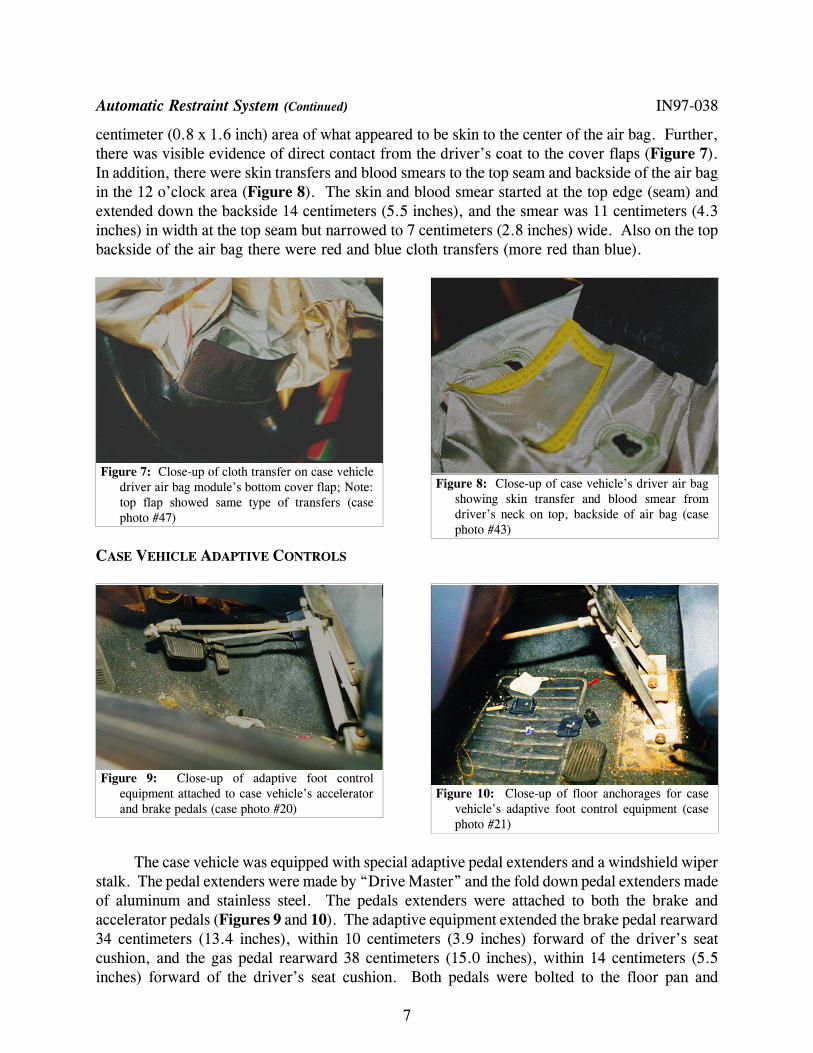
Figure 7: Close-up of cloth transfer on case vehicledriver air bag module’s bottom cover flap; Note:top flap showed same type of transfers (casephoto #47)
Figure 8: Close-up of case vehicle’s driver air bagshowing skin transfer and blood smear fromdriver’s neck on top, backside of air bag (casephoto #43)
Figure 9: Close-up of adaptive foot controlequipment attached to case vehicle’s acceleratorand brake pedals (case photo #20)
Figure 10: Close-up of floor anchorages for casevehicle’s adaptive foot control equipment (casephoto #21)
centimeter (0.8 x 1.6 inch) area of what appeared to be skin to the center of the air bag. Further,there was visible evidence of direct contact from the driver’s coat to the cover flaps (Figure 7).In addition, there were skin transfers and blood smears to the top seam and backside of the air bagin the 12 o’clock area (Figure 8). The skin and blood smear started at the top edge (seam) andextended down the backside 14 centimeters (5.5 inches), and the smear was 11 centimeters (4.3inches) in width at the top seam but narrowed to 7 centimeters (2.8 inches) wide. Also on the topbackside of the air bag there were red and blue cloth transfers (more red than blue).
CASE VEHICLE ADAPTIVE CONTROLS
The case vehicle was equipped with special adaptive pedal extenders and a windshield wiperstalk. The pedal extenders were made by “Drive Master” and the fold down pedal extenders madeof aluminum and stainless steel. The pedals extenders were attached to both the brake andaccelerator pedals (Figures 9 and 10). The adaptive equipment extended the brake pedal rearward34 centimeters (13.4 inches), within 10 centimeters (3.9 inches) forward of the driver’s seatcushion, and the gas pedal rearward 38 centimeters (15.0 inches), within 14 centimeters (5.5inches) forward of the driver’s seat cushion. Both pedals were bolted to the floor pan and
Case Vehicle Adaptive Controls (Continued) IN97-038
8
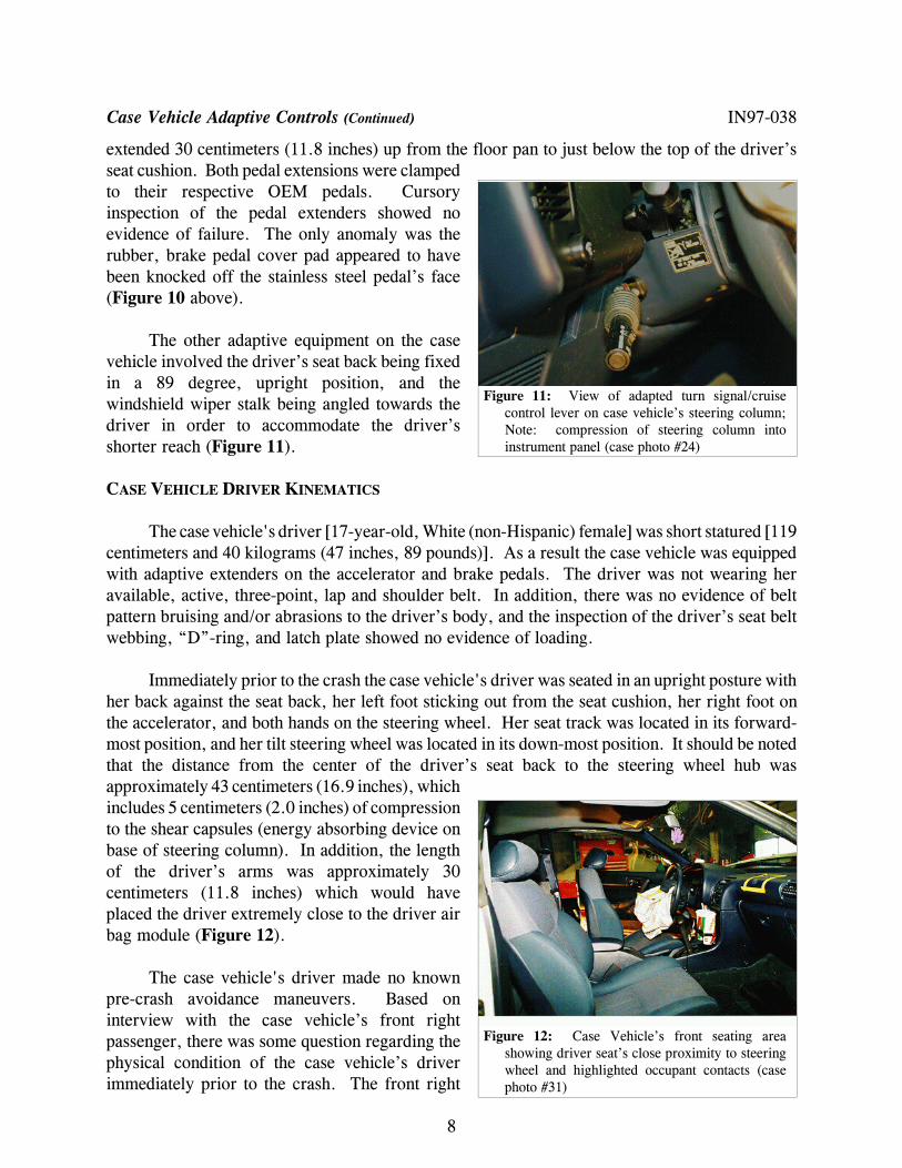
Figure 11: View of adapted turn signal/cruisecontrol lever on case vehicle’s steering column;Note: compression of steering column intoinstrument panel (case photo #24)
Figure 12: Case Vehicle’s front seating areashowing driver seat’s close proximity to steeringwheel and highlighted occupant contacts (casephoto #31)
extended 30 centimeters (11.8 inches) up from the floor pan to just below the top of the driver’sseat cushion. Both pedal extensions were clampedto their respective OEM pedals. Cursoryinspection of the pedal extenders showed noevidence of failure. The only anomaly was therubber, brake pedal cover pad appeared to havebeen knocked off the stainless steel pedal’s face(Figure 10 above).
The other adaptive equipment on the casevehicle involved the driver’s seat back being fixedin a 89 degree, upright position, and thewindshield wiper stalk being angled towards thedriver in order to accommodate the driver’sshorter reach (Figure 11).
CASE VEHICLE DRIVER KINEMATICS
The case vehicle's driver [17-year-old, White (non-Hispanic) female] was short statured [119centimeters and 40 kilograms (47 inches, 89 pounds)]. As a result the case vehicle was equippedwith adaptive extenders on the accelerator and brake pedals. The driver was not wearing heravailable, active, three-point, lap and shoulder belt. In addition, there was no evidence of beltpattern bruising and/or abrasions to the driver’s body, and the inspection of the driver’s seat beltwebbing, “D”-ring, and latch plate showed no evidence of loading.
Immediately prior to the crash the case vehicle's driver was seated in an upright posture withher back against the seat back, her left foot sticking out from the seat cushion, her right foot onthe accelerator, and both hands on the steering wheel. Her seat track was located in its forward-most position, and her tilt steering wheel was located in its down-most position. It should be notedthat the distance from the center of the driver’s seat back to the steering wheel hub wasapproximately 43 centimeters (16.9 inches), whichincludes 5 centimeters (2.0 inches) of compressionto the shear capsules (energy absorbing device onbase of steering column). In addition, the lengthof the driver’s arms was approximately 30centimeters (11.8 inches) which would haveplaced the driver extremely close to the driver airbag module (Figure 12).
The case vehicle's driver made no knownpre-crash avoidance maneuvers. Based oninterview with the case vehicle’s front rightpassenger, there was some question regarding thephysical condition of the case vehicle’s driverimmediately prior to the crash. The front right

Case Vehicle Driver Kinematics (Continued) IN97-038
9
Figure 13: Close-up of head contact on casevehicle’s driver sun visor; Note: short-statureddriver was seated directly underneath sun visor(case photo #28)
passenger stated that the driver did not respond to her two verbal warnings of the impending crash,and she also felt and heard the case vehicle accelerate prior to the crash. Three scenarios are: (1)the driver was incapacitated (i.e., blacked out) prior to the crash, (2) the driver panicked andpressed on the accelerator instead of the brake, or (3) the driver’s foot slipped off the brake andhit the accelerator causing the vehicle to speed up. According to the Medical Examiner, there wasnothing found during the autopsy that would indicate that the driver was incapacitated, and she hadno medical history of any episodes of blacking out. This contractor believes that the case vehicle’sdriver most likely hit the accelerator, either instead of or after she hit the brake pedal. This wouldexplain why the front right passenger stated she heard and felt the car accelerate prior to impact.As a result and independent of the nonuse of her available safety belts, her pre-impact bodyposition did not change just prior to impact. The case vehicle’s impact with vehicle #2 enabled the case vehicle’s driver to continueforward and slightly upward as the case vehicle decelerated. Due to the driver’s extreme closeproximity, the driver directly contacted the module’s cover flaps with her chest, blocking the airbag’s normal deployment path. This caused the deploying air bag to find subsequent avenues todeploy which resulted in the top cover flap beingcompletely blown off the air bag module. The topfront edge of the deploying air bag caught the casevehicle’s driver in her neck and underneath herchin, causing the neck and most likely her braininjuries. As the air bag continued to deploy, itlifted the driver upwards where she contacted thesun visor (Figure 5 above and Figure 13) prior torebounding back into her seat. At final rest thedriver was seated upright in her seat, her backagainst the seat back, her head tilted forward, andher body tilted slightly to the right.
CASE VEHICLE DRIVER’S INJURIES
The driver was transported by ambulance to the hospital. She sustained fatal injuries andwas pronounced dead 57 minutes post-crash. According to her medical records, the injuriessustained by the case vehicle’s driver included: minimal diffuse subdural and subarachnoidhemorrhages, minimal cerebral cortical contusions, fractures of the laryngeal cartilages, a minimalatlanto-occipital dislocation without trauma to the spinal cord, abrasions and superficial lacerationsto her neck, and a chest contusion. Based on an interview with the Medical Examiner, the driverdied of asphyxiation resulting from the swelling and soft tissue hemorrhage/hematoma in her neckthat compressed her larynx.

Case Vehicle Driver Injuries (Continued) IN97-038
1 The aspect “UNKNOWN” is encoded because the NASS CDS injury coding protocol does not allow the use of any aspects other than“LEFT,” “RIGHT,” or “UNKNOWN”.
2 The autopsy makes no specific mention of trauma to the larynx per se, either positively or negatively. According to our follow-upconversation with the physician who performed the autopsy, he indicated that the supporting laryngeal cartilage are part of thelarynx and that the larynx was neither perforated nor were the vocal cords damaged. When pressed about this patient’s cause ofdeath, the physician indicated that she died of the neck injury (i.e., the brain lesions and the atlanto-occipital dislocation weresurvivable). He indicated further that she died of asphyxiation resulting from the swelling and the soft tissue hemorrhage/hematomain the neck that compressed her larynx. Finally, the physician stated that he was never able to determine the source of thehemorrhage in the soft tissues of her neck.
3 According to the autopsy the following muscles were hemorrhagic: right sternocleidomastoid, right sternohyoid, both cricothyroid,and both posterior cricoarytenoideus (i.e., left greater than right) muscles.
4 According to the autopsy, significant displacement of the cervical vertebrae either to each other or to her skull (i.e., occiput) wasnot found. In addition, there was no injury to the spinal cord.
10
InjuryNumber
Injury Description(including Aspect)
NASS In-jury Code& AIS 90
Injury Source(Mechanism)
SourceConfi-dence
Source ofInjury Data
1 Hemorrhage, subdural, diffuse,minimal–location not specified[Aspect = Unknown]
140652.4severe
Air bag, driver’s Possible Autopsy
2 Contusion, cerebral, minimal–a“zone” limited to the corticalgray matter, location not spec-ified [Aspect = Unknown]
140606.3serious
Air bag, driver’s Probable Autopsy
3 Hemorrhage, subarachnoid, dif-fuse, minimal, most promi-nently distributed in interhemi-spheric midline1 [Aspect =Unknown]
140684.3serious
Air bag, driver’s Probable Autopsy
4 Fractures of right superior cornuaof thyroid cartilage and posteri-or (vertically) portion of cricoidcartilage with associated swel-ling and hemorrhage/hematoma2
into the strap3 muscles
340206.2moderate
Air bag, driver’s Probable Autopsy
5 Dislocation {separation} atlanto-occipital, minimal4
650208.2moderate
Air bag, driver’s Probable Autopsy
6 Abrasion, 2.5 x 16 cm (1.0 x 6.3in), across central anterior neck,horizontally–with addi-tionallinear abrasions under-lyinganteriorly
390202.1minor
Air bag, driver’s Certain Autopsy
7 Lacerations, superficial, neck 390602.1minor
Air bag, driver’s Probable Emergencyroom records
8 Contusion {bruising}, 8 x 8 cm(3.1 x 3.1 in), over sternum
490402.1minor
Driver module’scover flap
Certain Autopsy

11
Figure 14: Case vehicle’s front seating area viewedfrom outside right front door showing contacts(taped areas) to driver’s air bag and sun visor aswell as to dash and windshield on passenger’s side(case photo #32)
Figure 15: Close-up of starred windshield and make-up smear on top of case vehicle’s right instrumentpanel; Note: both contacts came from front rightpassenger (case photo #34)
CASE VEHICLE FRONT RIGHT PASSENGER KINEMATICS IN97-038
The case vehicle's front right passenger[friend, 16-year-old, White (Hispanic) female]was not wearing her available, active, three-point,lap-and-shoulder, safety belt system. The casevehicle was not equipped with a front rightpassenger air bag.
The case vehicle's front right passenger [160centimeters and 66 kilograms (63 inches, 146pounds)] was seated upright with her back leaningforward toward the center instrument panel (i.e.,she had just looked up from changing a CD), bothfeet on the floor, and both arms out-stretched withher hands on the instrument panel bracing for the impact. Her seat track was located in its middleposition, and the seat back was sightly reclined. At impact the front right passenger continuedmoving forward contacting the top of the instrument panel with her face and cracking thewindshield with the top of her head (Figures 14 and 15). Following the crash the front rightpassenger rebounded back into her seat as the vehicle came to final rest.
CASE VEHICLE FRONT RIGHT PASSENGER INJURIES
The front right passenger was transported by ambulance to the hospital. She sustained minorsoft tissue injuries and was treated and released. The self-reported injuries sustained by the casevehicle's front right passenger included: a contused and lacerated lip (from impacting theinstrument panel) and a contusion to the top back of her head from contacting the windshield.
Case Vehicle Front Right Passenger Injuries (Continued) IN97-038
12
Figure 16: Deformation to vehicle #2's back withcontour gauge present (case photo #55)
InjuryNumber
Injury Description(including Aspect)
NASS In-jury Code& AIS 90
Injury Source(Mechanism)
SourceConfi-dence
Source ofInjury Data
1 Contusion {bump} posterior toapex of scalp
190402.1minor
Windshield, rightof center
Certain Interviewee(same person)
2 Contusion {fat} lip, location notfurther specified
290402.1minor
Right dash/instru-ment panel
Certain Interviewee(same person)
3 Laceration lip, location notfurther specified
290600.1minor
Right dash/instru-ment panel
Certain Interviewee(same person)
VEHICLE #2
Vehicle #2 is a front wheel drive 1993 Plymouth Voyager SE, seven-passenger , four-doorminivan (VIN: 2P4GH45R8PR------) equipped with a 3.3L, OHV-SMPI, V-6 engine and a five-speed automatic transmission. Braking was achieved using a dual hydraulic, self adjusting frontdisk and rear drum system. Vehicle #2’s wheel base was 285 centimeter (112.3 inches), and theodometer reading at inspection was 128,313 kilometers (79,730 miles). The vehicle was equippedwith a supplemental restraint system (air bag) for the driver’s position only and three-point lap andshoulder belts for the front, second seat, and rear outboard seating positions. The rear center seathad a lap belt only. The interior was equipped with a bucket seat for the driver and a box-mounted nonadjustable bucket seat for the front right passenger. The second seating row had atwo-seat bench, while the rear bench seat accommodated three occupants.
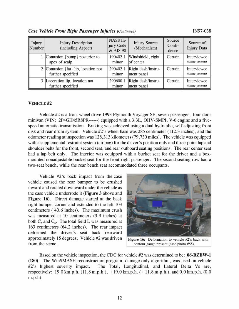
Vehicle #2‘s back impact from the casevehicle caused the rear bumper to be crushedinward and rotated downward under the vehicle asthe case vehicle underrode it (Figure 3 above andFigure 16). Direct damage started at the backright bumper corner and extended to the left 103centimeters ( 40.6 inches). The maximum crushwas measured at 10 centimeters (3.9 inches) atboth C5 and C6. The total field L was measured at163 centimeters (64.2 inches). The rear impactdeformed the driver’s seat back rearwardapproximately 15 degrees. Vehicle #2 was drivenfrom the scene.
Based on the vehicle inspection, the CDC for vehicle #2 was determined to be: 06-BZEW-1(180). The WinSMASH reconstruction program, damage only algorithm, was used on vehicle#2's highest severity impact. The Total, Longitudinal, and Lateral Delta Vs are,respectively: 19.0 km.p.h. (11.8 m.p.h.), +19.0 km.p.h. (+11.8 m.p.h.), and 0.0 km.p.h. (0.0m.p.h).

13
CV
V2
CV
V2
ST O P
Gouge from casevehicle's
undercarriage
RP Case vehicle'sFRP
V2 knockedfarther north ~35meters, prior tocoming to rest.
N Elementary schooldriveway
Scale: 1cm = 2.5 m
Dark w/ street lightsStraight and levelDry bituminous
SCHOOL
ZONE M.P.H.
15
SCHOOL
ZONE M.P.H.
15
STOP
IN9738
CRASH DIAGRAM IN97-038