Indiana Department Of Transportation Roadway Reference System Users… · materials), inventory...
33
Indiana Department Of Transportation Roadway Reference System Users’ Manual (a.k.a. the Reference Post System Made Simple) April, 1999 Developed & Prepared by: The Division of Roadway Management
Transcript of Indiana Department Of Transportation Roadway Reference System Users… · materials), inventory...

IndianaDepartment
OfTransportation
Roadway Reference System
Users’ Manual
(a.k.a. the Reference Post System Made Simple)
April, 1999Developed & Prepared by:
The Division of Roadway Management

A USERS GUIDEfor the
ROADWAY REFERENCING SYSTEM (RRS)
Revised May 1999 i
Table of ContentsList of Tables................................................................................................................................... iiList of Figures ................................................................................................................................. ii
INTRODUCTION............................................................................................................................... 1Why A Referencing System is Needed........................................................................................... 1What Is The Roadway Referencing System.................................................................................... 2
Operation............................................................................................................................................. 3ROADWAY REFERENCING SYSTEM....................................................................................... 3DATABASES and RRS.................................................................................................................. 4
Road Inventory............................................................................................................................ 4Bridge Inventory ......................................................................................................................... 4Other Databases .......................................................................................................................... 5
RRS and Road Inventory Compared............................................................................................... 5SIGN MAINTENANCE ................................................................................................................. 8
USING THE ROADWAY REFERENCING SYSTEM..................................................................... 8Travel – Over Routes .................................................................................................................... 10One Way Pairs............................................................................................................................... 11Bridges and the Referencing system ............................................................................................. 12Location Notation.......................................................................................................................... 12PROJECT LOCATIONS and DESCRIPTIONS .......................................................................... 14
PROJECTS ON NEW ALIGNMENTS OR NEW ROADS..................................................... 17OTHER USES............................................................................................................................... 18
APPENDIX....................................................................................................................................... 20SIGN PLACEMENT .................................................................................................................... 20

A USERS GUIDEfor the
ROADWAY REFERENCING SYSTEM (RRS)
Revised May 1999 ii
List of TablesTable 1: Reference Posts and County Log Mile System __________________________________________________6
Table 2: Multiple Countys, Reference Posts and County Log Miles _________________________________________7
Table 3: Database & Field Structure ________________________________________________________________9
List of FiguresFigure 1: RRS & Log-Mile System Comparison ________________________________________________________2
Figure 2: RRS & Log-Mile System with Relinquishments_________________________________________________3
Figure 3: Data Referenced to the Road ______________________________________________________________5
Figure 4: Multiple County Distance Calculation _______________________________________________________7
Figure 5: Travel – Over Routes ___________________________________________________________________10
Figure 6: Naming One – Way Pairs ________________________________________________________________11
Figure 7: Calculating Positive and Negative Offsets ___________________________________________________13
Figure 8: Project Location Description on One Route __________________________________________________14
Figure 9: Project Description on Multiple Routes _____________________________________________________15
Figure 10: Project Description with Missing Posts ____________________________________________________16
Figure 11: Numbering of New Road or Alignment _____________________________________________________17
Figure 12: Detail of Travel Over Routes ____________________________________________________________23
Figure 13: Detail of One - Way pair________________________________________________________________24
Figure 14: Detail Discontinuous Routes_____________________________________________________________25
Figure 15: Detail New Alignment __________________________________________________________________26
Figure 16: Detail Bridge Referencing_______________________________________________________________27
Figure 17: Detail Bridge Route Crossings ___________________________________________________________28
Figure 18: Detail Multiple Structures Same Location __________________________________________________29
Figure 19: Detail Non-State Road Overpass _________________________________________________________30

A USERS GUIDEfor the
ROADWAY REFERENCING SYSTEM (RRS)
Revised May 1999 1
INTRODUCTION
Why A Referencing System is Needed
For a modern roadway management system to function properly, information is required. Traffic
data, road roughness, condition evaluation, maintenance performed, history (age, costs,
materials), inventory (function, county, lanes, shoulders, access locations), pavement structure
components, bridges, drainage features, and accident history are some of the fundamental
building blocks of informed decision making. Such information must first: be available and
second be managed in such a way as to quickly provide the answers to questions asked by
individuals not only at all management levels but also of various disciplines to allow sound and
knowledgeable decisions.
Information that is compiled by means other than location, such as date, Contract number or
DES number, does not allow easy retrieval if a specific location is desired. Locations which are
narrative can not be easily sorted and are often inconsistent, varying greatly in reference to
county roads, city streets, municipalities, and land marks. Different highway log mile systems
have been developed but not correlated to each other, consequently, a large volume of
information has been gathered and stored but it is not readily accessible to various users due to a
lack of common location format or correlated references.
Each element of information described above can be related to a location on or along a road. A
clear, concise and easy to use method of reporting this information to a location is necessary in
order to retrieve and report the data. In addition the data must be related to common “reference
points” in a consistent manner.

A USERS GUIDEfor the
ROADWAY REFERENCING SYSTEM (RRS)
Revised May 1999 2
What Is The Roadway Referencing System
The Roadway Referencing System (RRS) is a means to relate a data element to a position or
extent along a road to a known point. The main distinction between the RRS and other systems
that use a “log-mile” method, such as the Road Inventory, is the Roadway Referencing System is
a means to report the location of information relative to a known, set point (reference post) along
a route, whereas the Road Inventory relates the point of information as a distance (Alog) from a
beginning point of the route (see Figure 1: RRS & Log-Mile System Comparison).
Figure 1: RRS & Log-Mile System Comparison
One major advantage to the RRS is that once set, the post location remains constant through time
and therefore any information related to that post stays constant through time unaffected by
realignments, or relinquishments occurring “upstream” from its’ location. The log-mile method
of relating occurrences as a distance (Alog) often requires the “relocation” of every occurrence
with any change occurring upstream (see Figure 2: RRS & Log-Mile System with
Relinquishments).
SR 16
Seco
nd A
ve.
A B
Third
Ave
.
Four
th A
ve.
Mai
n St
.
Firs
t Ave
.
Cou
nty
Line
Alog 0.00 Alog 0.35 Alog 0.85 Alog 1.50 Alog 1.87 Alog 2.15
Fifth
St.
Sixt
h St
.
Alog 2.65Alog 2.81
A - 100 A - 65 A - 15 A + 50 A + 87 B + 15 B + 65B + 81
Roadway Referencing System
Log-Mile System

A USERS GUIDEfor the
ROADWAY REFERENCING SYSTEM (RRS)
Revised May 1999 3
Figure 2: RRS & Log-Mile System with Relinquishments
The Roadway Referencing System (RRS) also provides uniformity to many elements of
information. The Referencing system allows data to be extracted for a particular section of road
from various computer files maintained by different individuals. All elements must be referenced
to the roadway in a consistent manner. The heart of the System is the installation of reference
signs on all state roads for quick and consistent reference to locations.
Operation
ROADWAY REFERENCING SYSTEM
Initially, reference signs are placed at nominal 1 mile increments, at the whole mile as
determined from the road inventory, on all “active” roads under INDOT jurisdiction. The
distance between signs within a given stretch of road may change due to a new alignment in that
area. The signs on the Interstate will remain as they currently are. The signs are continuous
numbered starting from zero at the south or west start of the road. For most purposes the south
or west start of the road can be determined from the numbering of the route. Odd numbered
roads run from South to North . Even numbered roads run from West to East. A few exceptions
SR 16
Seco
nd A
ve.
A B
Third
Ave
.
Four
th A
ve.
Mai
n St
.
Firs
t Ave
.
Cou
nty
Line
New Alog0.00
New Alog0.65
New Alog1.02 New Alog
1.30
Fifth
St.
Sixt
h St
.
New Alog1.80
New Alog1.96
A - 15 A + 50 A + 87 B + 15 B + 65B + 81
Roadway Referencing System
Log-Mile SystemRelinquished Section

A USERS GUIDEfor the
ROADWAY REFERENCING SYSTEM (RRS)
Revised May 1999 4
to this rule occur on the small "spur" roads which usually go to state parks or institutions or are
old state roads remaining after bypasses are placed. In any case, the direction as established in
the Road Inventory will control.
DATABASES and RRS
Road Inventory
The road inventory database is composed of two tables, one strictly numeric table and one text
table. The first table is used to track specific attribute data in numeric form along a route. It
uses the route/county intersection as it’s point of origination and termination for distance
measuring. The second table is comprised of a text field, an adjusted log mile field, and a sort
key combination. The text field is used to describe a landmark or point of interest. The adjusted
log mile (Alog), measured to the nearest 0.01 mile, relates that feature to (distance from) the
route/county line point. The sort key combination enables the text file to be “sorted in order”
with the strictly numeric tabular table to provide a more comprehensive view of the route.
The reference signs could be considered points of interest along the route and thereby
incorporated into the second of the two above mentioned tables. Once located in this manner,
the other points of interest could then be extracted with the distances shown as the reference
sign name “plus offsets” similar to stationing. Additional manipulations would be required to
extract the other significant attribute data maintained in the other table. Creating a relationship
between the three tables would be difficult under current practices.
Bridge Inventory
All bridges are marked with a reference sign which has the plus mileage (offset distance). A
mainframe file is maintained in which the reference sign, the bridge N.B.I., and structure number
are equated. In this way, knowing the reference location of the bridge from the reference sign,
information from the mainframe bridge inventory can be accessed and assimilated into and
compared with other datasets.

A USERS GUIDEfor the
ROADWAY REFERENCING SYSTEM (RRS)
Revised May 1999 5
Other Databases
Other data files which could be linked in this manner are project descriptions, accident reports
and permit locations. Then by knowing a location, information can be retrieved and compared to
other information such as ADT, pavement width or bridge data which is linked to the same
location. Examples of information which can be linked by location through the Referencing
system are shown in Figure 3.
Figure 3: Data Referenced to the Road
RRS and Road Inventory Compared
The reference signs are REFERENCE POINTS ONLY. The signs are "names" for known spots
on the road. The names happen to be, but are not required to be sequentially numbered along the
road. By being "names" for known locations the reference sign does not necessarily have to be
at the log mile the sign number indicates. The sign is placed to meet field conditions, to avoid
obstacles, and also adjusted for new alignments.
121 122 123 124 125
Reference System Typical State or US Highway
BridgeInventory
RP 122 + 0076
Road Inventory
Maint. Management Data
Contract Information
Roughness Data
Condition Data
Detail Detail Detail Detail Detail Detail Detail Detail
Roughness Roughness Roughness Roughness Roughness Roughness
Condition Condition Condition Condition
R-12345 R-67891 RS-18765
Maintenance Section Maintenance SectionBridgeSection

A USERS GUIDEfor the
ROADWAY REFERENCING SYSTEM (RRS)
Revised May 1999 6
Therefore, a record of the log mile as shown in the Road Inventory versus the reference number
("name") must be maintained. For example, when sign #101 is placed in the field, its continuous
log mile location can be 101.09 miles from the beginning of the route and have an Alog of 3.85
and this is recorded in the Road Reference file. The sign is a name to index information to the
Road Inventory Data Base. But it also serves as a close indicator of roadway mileage for
communicating locations. But, the signs are NOT "mile posts" or "mile markers" since total
distance can not be accurately determined from the name on the signs. Only the Road Inventory
Data Base can provide actual distances.
The Road Inventory Data Base, an actual cumulative distance file, allows the distance between
two references to be computed. For example, given two references on a route to describe a
project start and end limits, RP 245+30 and RP 258+80, the accurate length, for engineering
purposes, is not the difference between these points. The actual locations of reference signs 245
and 258 must be known. The two references define the project location and can give an
approximate length. The start of the job is 0.30 miles beyond reference sign 245. The Road
Inventory Data Base provides the information for determining more accurate lengths. Suppose
the Reference File contains the following entries for these reference signs:
Table 1: Reference Posts and County Log Mile System
Reference Sign Log Mileage (county log method)245 24.97258 38.04
The distance between the two reference signs is 38.04 -24.97, or 13.07 miles, not 13 miles (258-
245). The length of the project is 13.07 + 0.80 -0.30, or 13.57 miles. But if the references are
subtracted; (258+80)-(245+30)= 13.50. This is not the length of the project. The start of the
project is 0.30 miles beyond 245 reference sign, and can be physically located in the field and in
the data file. The "log mileage" is not needed unless an accurate distance calculation is desired.
A complication which occurs due to the Road Inventory restarting the Adjusted log mileage to
zero at each county line. In the previous example, the two references could have been in two

A USERS GUIDEfor the
ROADWAY REFERENCING SYSTEM (RRS)
Revised May 1999 7
different counties, so that the entries in the Reference File might be as follows: (See Table 2 &
Figure 4).
Table 2: Multiple Counties, Reference Posts and County Log Miles
Reference sign Log Mileage County245 24.97 1258 8.04 2
The Reference file also shows County 1 ends and County 2 begins at log mile 30.07. The actual
distance between RP 245+30 and RP 258+80 is as follows: 30.07 - (24.97 + 0.30) + (8.04 +
0.80) = 13.64 miles as shown below.
Figure 4: Multiple County Distance Calculation
In general the method for determining distance when in two different counties is: (ENDING COUNTY LINE MILEAGE - START MILEAGE + END MILEAGE)Where in this example: START =RP 245+30 = 24.97 + 0.30 and
END =RP 258+80 = 8.04 + 0.80
For most purposes the subtraction of the Start and End reference will be close to the actual
distance. Upon installation the reference signs are very close to the true distances. Only as our
roads change in length will the actual mileage vary from the Reference Sign's number.
245 25824.97 log mile
30.07 log mile8.04 log mile
Project StartRP 245 + 0030
Project EndRP 258 + 0080CO. #1 CO. #2
Cou
nty
Line
0.3 30.07 - (24.97 + 0.30) 8.04 0.80
True Distance30.07-(24.97 + 0.30) + (8.04 + 0.80)
13.64 Miles Not to Scale!

A USERS GUIDEfor the
ROADWAY REFERENCING SYSTEM (RRS)
Revised May 1999 8
This type of manipulation is also needed to convert existing P.C. inventories in county log
format to the referencing system method.
SIGN MAINTENANCE
The repair or replacement of reference signs to keep the referencing system usable is a District
sign maintenance activity. Sign installations that are leaning, have holes, or have lost legibility
will be noted for replacement. If the location for a missing sign is not physically evident, the
replacement location must be verified with the District or Roadway Management in the central
office before replacement. Missing signs must be replaced within 0.01 mile of its original
position. The periodic replacement of reference signs to provide adequate legibility will
constitute a district sign replacement activity. This work should be scheduled in conjunction
with other sign replacement programs.
None of the above mentioned activities includes installation of new signs due to construction
activities. Such work should be included in RS, R, T, and B contracts. Contracts must make
provisions to allow for the removal and proper replacement of the Reference Signs. If removed
for construction activities, the sign must be replaced in the same approximate location as it was
previously, if possible. If a sign must be relocated inform the Roadway Management. New
alignments, new roads, and new bridges, must consider the placement of corresponding reference
signs.
USING THE ROADWAY REFERENCING SYSTEM
The description reporting of locations on and along the road are a daily activity by many people.
The Roadway Referencing System is an easy way to find locations along a road without back
tracking to a county line. An accident, work site, address, drive or any location can be
communicated as a distance, measured from a the nearest reference sign, i.e. 0.5 miles north of
Reference Sign 76 or .3 miles south of Reference Sign 13 and would be noted as 76 + 0050 and
13 – 0030 respectively.

A USERS GUIDEfor the
ROADWAY REFERENCING SYSTEM (RRS)
Revised May 1999 9
The reference signs are located to the nearest 0.01 mile with a precision of plus or minus 26 feet.
Therefore it is necessary to remember that they are NOT surveying monuments. Nor should they
be used for engineering detail. The reference signs ARE more than precise enough for activities
such as radio communications, crew work site locations, and other daily operations where
odometer precision is sufficient. In order to use the Roadway Referencing system to describe
more precise locations, the use of a DMI (Distance Measuring Instrument) should be considered.
For consistent reporting of information by location using the Road Referencing System a few
rules and conventions must be used by all divisions/departments/districts. The key for data files
to be relational by location is to use consistent ROUTE NAMES and REFERENCE
LOCATIONS. All location information must follow the form of Route Type, Route Name,
From, To or At. The format that follows shows how and what information should be recorded
for consistent reporting of location descriptions. It is not necessary data be in this order, but
must it be in separate fields as shown. Each application must be examined as to how this
information can be implemented. Contact Roadway Management for help in coordinating
reports and data files.
Table 3: Database & Field Structure
RouteType
RouteNo.
Direction1 FromRef. Post
From Ref.Offset2,3
To Ref.Post
To Ref.Offset
A NNN A NNN NNNN NNN NNNN A = AlphaN = No.
I 65 I 201 45 207 6U 421 D 140 102 142 56S 8 I 3 75 15 5
NOTE: 1"Direction" is not the compass direction of the piece of road but the primary direction of travel where
direction “I” = increasing post number (Northbound or Eastbound) and “D” = decreasing post number
(Southbound or Westbound). US 421 is a N & S road and US 8 is an E & W road. See page 9 for more details.2”Offset” is measured in hundredths of a mile with an assumed decimal place( e.g. 102 = 1.02miles, 54 = .54
miles). 3 From post and offset are to be used as the description for bridge, culvert work, or sign work, which is
considered to be “AT” a location.

A USERS GUIDEfor the
ROADWAY REFERENCING SYSTEM (RRS)
Revised May 1999 10
In addition to the required information, a narrative "From" & "To" is helpful in understanding of
where RP 142+56 is on US 421.
Travel – Over Routes
The Route Type, Route Name and Reference Point define a specific From/To/At. The Route
Name must be correct to get the information filed in the right place. The Route Name may be
question on travel-overs and one-way pairs. It can also be a problem if directional information is
being used. In all cases the Route Name must carry the Route Type. There are some routes of
different type with the same number (I 65 and SR 65).
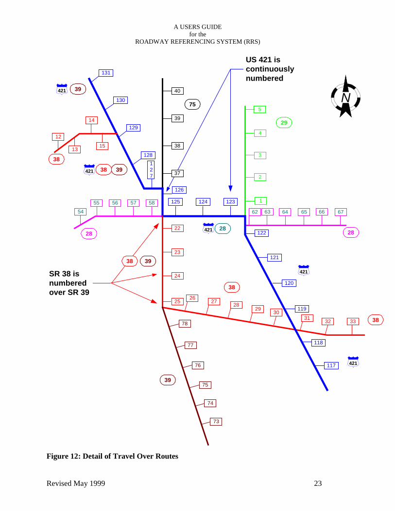
“Travel - overs” occur when two or more routes “travel – over” the same section of pavement.
For data maintenance purposes one of the two routes is designated as the primary route and all
attribute data is assigned (or tracked) by this route. The rules for determining which route takes
precedence are simple. 1) Interstates take precedence over US routes, which take precedence
over State Roads. 2) When two routes of the same type are involved, the route with the smaller
number takes precedence( see Figure 5). There are a few exceptions to this rule, the most
notable being I-465. Following the rules I-465 would travel – over I-74, but in reality the section
is reported as I-465.
Figure 5: Travel – Over Routes
62 64
14
16
SR 1
3
SR 1315
SR 1
3
SR 18 SR 18
SR 18 Reference PostSign
SR 13 Reference PostSign

A USERS GUIDEfor the
ROADWAY REFERENCING SYSTEM (RRS)
Revised May 1999 11
One Way Pairs
In essence a one-way pair is two different state roads which happen to share the route type and
the route name. For location descriptions on “one-way Pairs”, the Route Type and Name must
be clear as to which street is being referred to. Each section (street) of the one way pair must
have the travel direction, Increasing or Decreasing, noted in the Route Type/Number/Direction.
For example the one-way pair in Terre Haute is US 40 I (eastbound) and US 40 D (westbound).
Thus two unique names for the road are made to fit into the proper file slot. Direction is noted
as Increasing distance from the beginning of the road (the primary direction of the route
Eastbound or Northbound) or decreasing the distance from the beginning of the route (secondary
direction of the route – Southbound or Westbound).
Figure 6: Naming One – Way Pairs
The same I or D designation applies to data which is directional, such as roughness or a project
which is on one lane or side of the road. If no direction is indicated, normal, bi-directional routes
are assumed. "B", for bi-direction must be used if data is sometimes directional. Each
application must be examined for direction. For some applications direction is of no concern.
Others may need, or prefer left and right as data fields. These applications should be discussed
with Roadway Management to check for compatibility.
7
7
US 40 D
US 40 I
6 8US 40

A USERS GUIDEfor the
ROADWAY REFERENCING SYSTEM (RRS)
Revised May 1999 12
Bridges and the Referencing system
Bridges are inventoried and referenced to the Referencing system. Signs are installed that
represent the Reference Location for each bridge. Theoretically the distance shown is to the
mid-point of the structure. For most purposes the inventory reference sign for that bridge should
be used in the From for the location along with the Route Type and Number. Direction of travel
is also needed for twin structures. "R" for ramps is also shown on some structures. Both the
direction and ramp designation is shown on the signs and inventory. These too must be used
when referring to a structure. These locations are "equated" to the bridge structure number and
can be used instead of the bridge structure number to identify any bridge. The reference number
of the bridge should be used in any project description when bridge rehabilitation or
replacements are within a larger "R" contract.
Intersections of State Roads with other State Roads at a grade separation or interchange are
assumed to meet at the point where the two center lines intersect. Ramps are not referenced or
included in travel distances. Ramp inventories exist and the distances exist, but are not part of
the Referencing system.
Location Notation
The other item for location information is the point of reference used by the Referencing system.
The reference signs are points of reference only! They are a series of known locations along a
road which we are "naming" with sequential numbers. It just so happens that they also closely
follow the accumulated mileage along the route. The same results would occur if the signs were
marked A, B, C, D, ...AA, AB, etc. The reference signs are used to locate positions on the road.
Each "From", "To", & “AT” point must be referenced from a “whole” road reference sign.
(Points along the road should not be measured from Bridge Reference Signs!) The format for
notation is "Reference Sign + Mileage" or "Reference Sign - Mileage". RP 143 + 43 is the
normal fashion to write a "From", "To" & “AT” and the preferred method. The plus or minus
distance is called the Offset. However, if Sign #143 and #144 are 1 mile apart, then RP 144-57
describes the same location as RP 143+43.

A USERS GUIDEfor the
ROADWAY REFERENCING SYSTEM (RRS)
Revised May 1999 13
Because of travel-overs, one-way streets and divided highways the RP “ + ” or “ – ” distance has
benefits depending on the direction of travel, and whether a location is known and a reference is
needed, or whether a reference is known and a position on the road is needed. The direction of
travel may only let you measure in one direction. Or the closest sign may be ahead a short
distance while the sign behind is several miles back before a travel-over. Care must be given to
the fact that the Reference Signs may not be 1 mile apart. RP 144-50 is not the same location on
the road as RP 143+50 if Sign #144 and #143 are more or less than 1.00 mile apart. (For day-to-
day use with odometer this difference will be minor, if noticeable.) For data entry purposes the
Reference Point must be converted from "-" format to the equivalent "+" format. To do this the
distance between the posts must be determined and the minus distance is subtracted from this to
get the equivalent plus location.
Figure 7: Calculating Positive and Negative Offsets
If a location like the intersection of two state roads or a major feature is being described, it may
be easier and will be more precise to look up the reference plus in the inventory. The sign and
landmark pluses are shown on terminals for office use. Print-outs can be made.
SignA
SignB
SignC
PX1 X2
d1 d3d2
d1 + d2 = X1
Point P = A "+" d1 or B "-" d2 or C "-" (d3 + d2)Point P = A "+" (X1 - d2) or B "-" (X1 - d1)
Where A, B, and C are the Sign Post Designators

A USERS GUIDEfor the
ROADWAY REFERENCING SYSTEM (RRS)
R
PROJECT LOCATIONS and DESCRIPTIONSAll project, contract and work area descriptions for work on “active” INDOT jurisdiction routesmust show the location using the Referencing system. Work and projects on Local PublicAgency, institution locations and “old state road” locations will not have references and cannotfollow the system. By using consistent location descriptions, DES, Project, and Contractnumbers can be correlated by location. As described before, each project location must containthe following elements:
"sD
F
ROUTE: Type & Number DIRECTION(optional):___ FROM:_____ TO:_____NARRATIVE: FROM:________ TO:_________
evised May 1999 14
FROM" always starts at the lower reference number. The offset for the "FROM" and "TO"hould be shown to the nearest 0.01 mile and should be shown in the normal format of "SIGN +ISTANCE". See the following examples of project descriptions.
igure 8: Project Location Description on One Route
US 231
County Line
SR 162
Project Limits
27 28 29
Route: US 231 From: RP 27 + 27 TO: RP 29 + 48Narrative: On US 231 from .7 mile south of SR 162 to .4mile south of the Warick Co. line.
Note: Direction is not needed.

A USERS GUIDEfor the
ROADWAY REFERENCING SYSTEM (RRS)
Revised May 1999 15
In this example SR 218 travels over SR 5. The project really starts on SR 5 and the description
using the Referencing system must show the proper route and then the proper reference points
for the respective routes. The narrative conveys the simplest description. As a side note, caution
should be used when defining projects extending over various routes. The need, standards or
importance may not be the same for the various segments. Also, local usage of route numbers
must be checked. Not all routes are named what they may be considered locally.
Figure 9: Project Description on Multiple Routes
RS - 18656 Project
I - 69
SR 5
SR 3
SR 218 SR 5
SR 5
52 13 14 15 1617
18
19
58
59
60 61 6212
11
10
SR 218RP 13 + 56
RP 57 + 56
RP 17 + 71RP 61 + 44
Narrative: On SR 218 From I - 69 to SR 3
ROUTE: SR 5 FROM: RP 13 + 56 TO: RP 17 + 71
ROUTE: SR 218 FROM: RP 57 + 56 TO: RP 61 + 41

A USERS GUIDEfor the
ROADWAY REFERENCING SYSTEM (RRS)
Revised May 1999 16
In this example the project starts on a State Route which begins after traveling over a US route.
The signs are continuous for the US route. No sign #15 or #16 exists on the State Route. What
is the reference for the start of this project? One possible answer is RP 17-85. The start of the
project could also be determined from Sign #14 or from the inventory data which shows this
intersection measured from an Imaginary Sign #16. For most applications RP 17-85 should be
converted to RP 16+15. In this case the number can be subtracted since Sign #16 exists only on
"paper" and is considered to be exactly one mile from Sign #17.
Figure 10: Project Description with Missing Posts
Not all projects follow a single "Route/From/To" description. Examples are Raised Pavement
Marker, Mowing, or Guard Rail Maintenance contracts which use descriptions like; Various
routes, Various locations. Efforts should be made to assign the work to a route and reference
when possible. But some projects, such as district wide guard rail repair or traffic maintenance
contracts have no assignment to location. For these types a route of SR 00, a reference of "From"
500 and district should be used . This is a catch-all file and makes retrieval difficult, so should
be used as little as possible.
US X
US
X
US
X
SR A
START OF PROJECT
SR A
14 17102 103
101
104
.85 MI2.15 MI
Note: NOT to SCALE

A USERS GUIDEfor the
ROADWAY REFERENCING SYSTEM (RRS)
Revised May 1999 17
PROJECTS ON NEW ALIGNMENTS OR NEW ROADS
Projects on completely new alignments or new roads pose a different problem. Generally, these
projects do not have anything to reference from since they are new. Stationing is used as the
design and construction layout. It must be determined at some time where the survey line
intersects an existing route. A statement equating a survey station to the existing Reference
Point at that intersection must be shown on the project. Then a Reference Point of 900 is
assigned this location on the new alignment. Subsequent projects from this one point can then be
referenced using the project length and the 900 reference starting point for the location reference.
Final Reference Signs can be determined when the road is completed. The use of the 900 series
on the new alignment is necessary since the new alignment has the same route name as a portion
of existing highway. Until the old highway is abandoned, or renamed the 900 series allows
references to be made on the new road.
Figure 11: Numbering of New Road or Alignment
Details in project designs, such as typical sections within resurface contracts, should use the
referencing system to show the limits of the Typical Sections. Layout of construction signs or
Exis
ting
Roa
d
Existing Route
Project Project
Project
RP 900 =Sta 10 + 00 =SR XX @ Sta 220+ 35.67
RP 902 + 75 =Sta 155 + 20
RP 908 + 44 =Sta 455 + 05
RP 905 + 37

A USERS GUIDEfor the
ROADWAY REFERENCING SYSTEM (RRS)
Revised May 1999 18
wedging limits can also use the referencing system. A detail which does not need precision, but
general accuracy is desired, can use the system and is encouraged. By using the system for
typical sections, ease in maintaining pavement structure history is enhanced. Also, details such
as Deflection tests or pavement cores taken prior to the project can be located easier.
OTHER USES
Project descriptions are not the only application of the Referencing system. One desirable use is
for permit applications for drives and cut permits. The system allows for consistent location on
the road both current and historically of work activities done by non-highway operations. The
same rules and procedures would apply where all information should be filed using the
"Route/From/To" format. This application may need direction or right & left information in the
format.
Testing locations for cores, samples, or deflection should also use the referencing system. The
locations of such test results can be referenced to later project development locations easier and
with more certainty.
Surface condition information will be taken and recorded using the referencing system. This will
allow repeated measurement of the same location on the road over time. With roughness,
condition, and contract information tied to historically constant locations, retrieval of
information is simplified. Also, the location of the piece of road the numbers are supposed to
represent can be found and checked.
Another use which may have possibility is in the video logging being done. The sign will help
locate features of interest. If a feature's reference and plus is known the sign in the picture can
help locate the information. Further refinements of this are possible.

A USERS GUIDEfor the
ROADWAY REFERENCING SYSTEM (RRS)
Revised May 1999 19
Information on maintenance activities can be recorded using the signs along with the
maintenance section, for more precise details of daily work activities. Maintenance sections are
linked to the Referencing system.
Accident information and locations can use the System. Coordination with law enforcement
people is needed to make them aware of the possibility and for proper reporting.
Information and Inventory expansion must use the referencing system. If inventories for pipe
structures, guard rail, bill boards or RR crossings exist or are built in the future, the system
provides a link for others to use the information if the need arises. Drainage structure inventories
are an area of need for which the system can be used both locally and state wide. The current
sign inventory can inventory the reference signs like any other sign and provide the link for the
referencing system to other existing inventories which may use the no-passing zone log.
The reference sign is a visible reminder of the established method of referencing locations on the
highway transportation network. The signs provide clear indications for referencing data
collected in the field. As information is collected whether from INDOT, Police, or motorists, the
sign is easily available and a reminder for locating and communicating uniform positions on the
roads. Location in the field of specific road elements (such as county road intersections, bridges,
pipes, and so forth) will be made clearer. Translation of inconsistent descriptions to consistent
locations will not be needed.
The Roadway Referencing system sign represents a concerted effort by the Department to
expand our knowledge base and unify our management procedures. To derive the maximum
benefits, the Roadway Referencing system must be used and the highway population, law
enforcement agencies, and highway user groups must be educated to its function and potential
uses. Each department should examine its information needs and evaluate how the Roadway
Referencing system can be used for communicating information. Contact Roadway
Management for coordination and assistance in using or developing applications of the System.

A USERS GUIDEfor the
ROADWAY REFERENCING SYSTEM (RRS)
Revised May 1999 20
APPENDIX
SIGN PLACEMENT
Reference signs, except on the Interstate which will remain the same, shall be horizontal panels
having overall dimensions of 6 inch by 12 inch with 3 inch white numerals on a blue background
with a 1/2 inch white border. The sign shall be fabricated in accordance with INDOT Standard
Specifications. The sign shall be made with reflective sheeting Type II (encapsulated lens). The
sign shall be mounted on a Type "A" flanged channel post and fastened per INDOT Standard
Specifications.
Signs should be erected on a separate mounting. The erection location should be in a protected
area (to avoid being damaged) on the right side (looking in the ascending direction) with the sign
face parallel to the road. In urban areas, the signs can be correctly placed on existing supports
used for other purposes, such as traffic signals, or other existing INDOT hardware.
The sign should be mounted so that the bottom of the sign is approximately 4 feet above the near
edge of pavement. The height of the post may vary in urban locations. More than 4 feet is
needed along sidewalks or areas of pedestrian traffic. The post shall be driven a minimum of 2'-
6" into the ground. The sign shall be placed not less than 6 feet outside the outer edge of the
shoulder or face of curb. Other pluses, such as at the R/W or fence line should be considered on
roads with narrower Right-of-ways. Each road must be evaluated for the best offset position to
avoid mowers, ditches or embankments and remain visible. Effort should be made to place the
signs at a consistent offset for the given section. The sign should be immediately behind guard
rail if present. The sign should also be in line with any run of delineators as may exist.
When a sign cannot be erected in its correct mileage location, it may be moved in either direction
to the closest feasible point to the true location. This location must be recorded in the Road
Reference file.

A USERS GUIDEfor the
ROADWAY REFERENCING SYSTEM (RRS)
Revised May 1999 21
On four (4) lane or greater highways (divided and undivided), distance determination shall be
made from northbound and eastbound lanes for the purposes of setting the signs. The signs for
southbound and westbound lanes shall be set at locations directly opposite.
With travel-over routes (two routes on the same road), continuity shall be established for
only one of the routes. The reference signs are located for the major through route as designated
in the Road Inventory file. The major through route is generally defined as Interstate over U.S.,
U.S. over State Road, and the smaller numbered over other when the two routes are of the same
type (in most cases). The route without reference sign continuity has the first sign past the travel-
over area reflects the distance along that route as if the travel-over did not exist. (Route plaques
are added to the post on the travel-over section for clarity when needed to show to which route
the reference signs belong.) (See example page 19)
On one-way pairs in cities the signs are placed on both of the one way streets. The consecutive
signs are placed in 1 mile increments from the last sign on the two-way section for the street in
the ascending direction. The first sign past the one-way pair is located in its correct location
based on the Road Inventory as any other reference would be. From this first sign past the one-
way pair the direction of travel is reversed and the signs on the descending direction street are
placed in one mile increments from this sign in descending order. (See example page 20).
Discontinuous routes (routes which end within the state and start again some distance away and
are not connected) are measured and marked as any route for the first segment. The second
segment, where the route starts elsewhere in the state, begins with referencing at the reference
number where the first segment ended plus 0.01 mile. This makes the end of the first segment
reference point XX+XX and the start of the second segment XX+XX + 0.01 mile. This makes
each reference name on the road unique. A sign is not placed on the second segment until the
whole mileage point occurs, however. (See example page 21)
A roadway section that is under construction and/or not yet open to traffic, for purposes of
measurement and reference sign placement, will be treated as continuous with the roadway

A USERS GUIDEfor the
ROADWAY REFERENCING SYSTEM (RRS)
Revised May 1999 22
portion in existence and ascending reference signs established accordingly. Contact Roadway
Management for assistance.
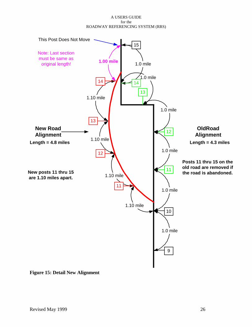
Future roadway construction, such as new alignments, bypasses, or abandonment will change the
length of portions of the route. A means of referencing the new roadway section is needed. The
signs within the affected section will be adjusted to cover the new distance. In other words, a
pair of signs originally placed 1.00 mile apart on the old road may be relocated so as to be 1.10
miles apart on the new. Ascending signs past the affected section will not require relocation nor
renumbering. New entries into the Reference File will establish a new, revised record of the
actual mileage and location of the relocated reference sign's number. The old road will be
abandoned or renamed. (Remember, a feature of the Roadway Referencing system is the signs
are references only and do not reflect the exact mileage. The number on the sign is the name of a
known location. When a reference sign number on the road is used, the location is known and
can be converted to actual mileage.) (See example on page 22).
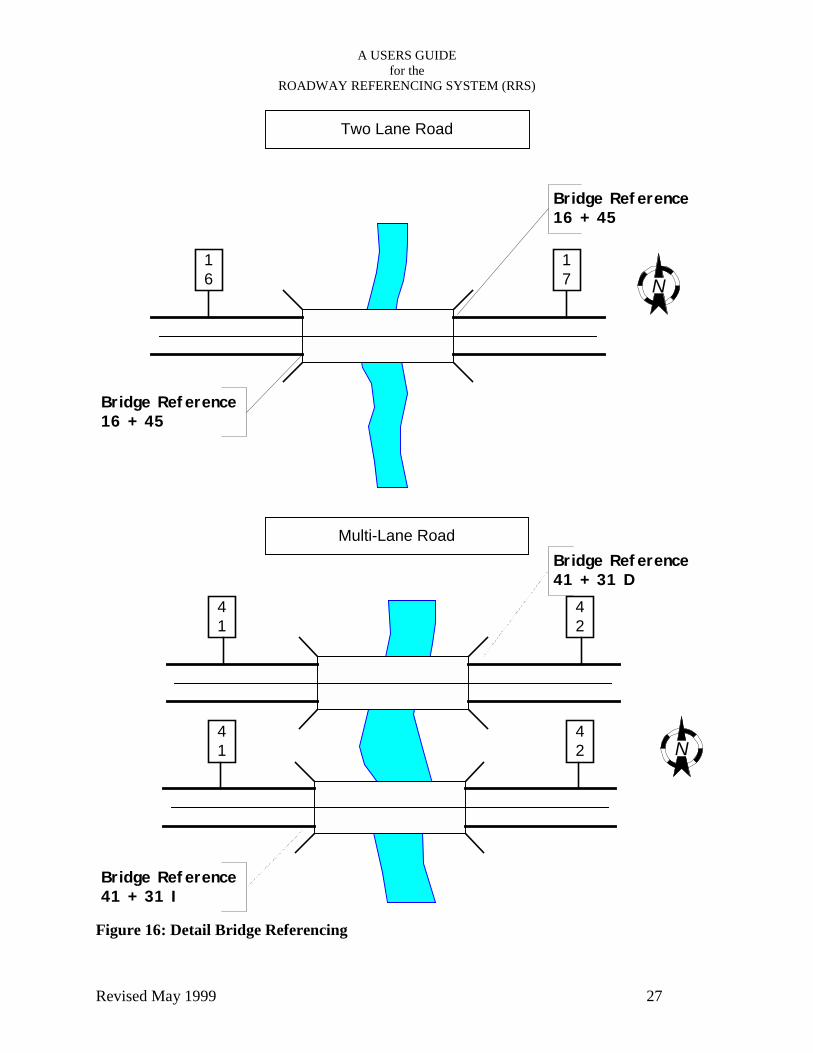
Placement of signs at bridges is shown on pages 23 through 26. Each bridge has a reference
sign. The route with state jurisdiction which travels over the bridge deck is the route and sign
reference to be used. Bridges such as county roads over the interstate are referenced on the
interstate. But a state road over the interstate is referenced on the state road. Bridges such as
twins on the interstate have a letter for the direction of travel to differentiate the two structures at
the same location and with the same basic structure number.
Bridges on ramps are referenced from the approximate mainline reference location and may
carry the letter "R" to differentiate these from mainline structures. Only one double- faced sign
is placed on two lane roads per structure. On multi-lane roads a sign in each travel direction is
placed. See the diagrams for more details.
A USERS GUIDEfor the
ROADWAY REFERENCING SYSTEM (RRS)
Revised May 1999 23
Figure 12: Detail of Travel Over Routes
131
130
129
128127
126
125 124 123
122
121
120
119
118
117
40
39
38
12
13
14
15
22
23
24
25 27 2829 30
31 32 33
26
5455 56 57 58
62 63 64 65 66 67
5
4
3
2
1
78
77
76
75
74
73
N421 39
421
421
421
421
39
3938
38
28 2828
29
39
38
75
38
US 421 iscontinuouslynumbered
37
SR 38 isnumberedover SR 39
38

A USERS GUIDEfor the
ROADWAY REFERENCING SYSTEM (RRS)
Revised May 1999 24Figure 13: Detail of One - Way pair
5th St.
Cherry St.
11th St.
14th St.
N
40
40
ON
E WA
YO
NE W
AY
ONE WAY
ON
E W
AY
ON
E W
AY
ONE WAY
ONE WAY
41 41
6
7
8 8
7
6
1.0 mile
1.0 mile
0.83 miles
1.0 mile

A USERS GUIDEfor the
ROADWAY REFERENCING SYSTEM (RRS)
Revised May 1999 25
Figure 14: Detail Discontinuous Routes
EndSection # 1RP 33 + 48
N
35
35
421231
14
17
14
114 114
3933 34
BeginSection # 2RP 33 + 49
A USERS GUIDEfor the
ROADWAY REFERENCING SYSTEM (RRS)
Revised May 1999 26
Figure 15: Detail New Alignment
13
12
11
10
13
12
9
1.10 mile
1.10 mile
1.10 mile
1.10 mile
1.00 mile
1.0 mile
1.0 mile
1.0 mile
1.0 mile
1.0 mile
14
1.0 mile
11
14
15This Post Does Not Move
Note: Last sectionmust be same as
original length!
New RoadAlignment
Length = 4.8 miles
OldRoadAlignment
Length = 4.3 miles
Posts 11 thru 15 on theold road are removed ifthe road is abandoned.New posts 11 thru 15
are 1.10 miles apart.
A USERS GUIDEfor the
ROADWAY REFERENCING SYSTEM (RRS)
Revised May 1999 27
Figure 16: Detail Bridge Referencing
Two Lane Road
Multi-Lane Road
16
Bridge Reference16 + 45
Bridge Reference16 + 45
41
41
42
42
N
N
Bridge Reference41 + 31 I
Bridge Reference41 + 31 D
17

A USERS GUIDEfor the
ROADWAY REFERENCING SYSTEM (RRS)
Revised May 1999 28Figure 17: Detail Bridge Route Crossings
Stat
e Ro
ad O
ver
Inte
rsta
teSt
ate
Road
Und
er I
nter
stat
e 41
41
42
42
N
N
Bridge Reference41 + 31 I
Bridge Reference41 + 31 D
90
90
206
No Sign
No Sign
Bridge Reference7 + 25
Bridge Reference7 + 25

A USERS GUIDEfor the
ROADWAY REFERENCING SYSTEM (RRS)
Revised May 1999 29
Figure 18: Detail Multiple Structures Same Location
STR
.12
3
STR
.12
3
STR
.12
4
N
8 8
7 7
+ 15 I
+ 15 D
+ 15 R
All Three Structuresat same log mile
Reference Signs:STR. 123 = 7 + 15 ISTR. 123 = 7 + 15 DSTR. 124 = 7 + 15 R
Ramp

A USERS GUIDEfor the
ROADWAY REFERENCING SYSTEM (RRS)
Revised May 1999 30
Figure 19: Detail Non-State Road Overpass
County Road & Other Non-StateOverpass
N
No Sign
No Sign
Bridge Reference7 + 45
Bridge Reference7 + 45
7
7
8
8