Indian Institute of Technology Kanpur Gujarat State ... · Indian Institute of Technology Kanpur...
136
IITK-GSDMA GUIDELINES on MEASURES TO MITIGATE EFFECTS OF TERRORIST ATTACKS ON BUILDINGS Indian Institute of Technology Kanpur Gujarat State Disaster Mitigation Authority July 2007
Transcript of Indian Institute of Technology Kanpur Gujarat State ... · Indian Institute of Technology Kanpur...
IITK-GSDMA GUIDELINES on MEASURES TO MITIGATE EFFECTS OF TERRORIST ATTACKS ON BUILDINGS
Indian Institute of Technology Kanpur
Gujarat State Disaster Mitigation Authority
July 2007

Other IITK-GSDMA Guidelines: • IITK-GSDMA Guidelines for Seismic Design of Liquid Storage Tanks
• IITK-GSDMA Guidelines for Structural Use of Reinforced Masonry
• IITK-GSDMA Guidelines for Seismic Design of Earth Dams and Embankments
• IITK-GSDMA Guidelines for Seismic Evaluation and Strengthening of Existing Buildings

(i)
IITK-GSDMA GUIDELINES on MEASURES TO MITIGATE EFFECTS OF TERRORIST ATTACKS ON BUILDINGS
Prepared by: Indian Institute of Technology Kanpur Kanpur
With Funding by: Gujarat State Disaster Mitigation Authority Gandhinagar

The material presented in this document is to help educate engineers/designers on the subject. This document has been prepared in accordance with generally recognized engineering principles and practices. While developing this material, many international codes, standards and guidelines have been referred. This document is intended for the use by individuals who are competent to evaluate the significance and limitations of its content and who will accept responsibility for the application of the material it contains. The authors, publisher and sponsors will not be responsible for any direct, accidental or consequential damages arising from the use of material content in this document.
Preparation of this document was supported by the Gujarat State Disaster Management Authority (GSDMA), Gandhinagar, through a project at Indian Institute of Technology Kanpur, using World Bank finances. The views and opinions expressed in this document are those of the authors and not necessarily of the GSDMA, the World Bank, or IIT Kanpur.
The material presented in these guidelines cannot be reproduced without written permission, for which please contact: Co-ordinator, National Information Center for Earthquake Engineering, Indian Institute of Technology Kanpur, Kanpur 208 016 ([email protected]).
Copies of this publication can be requested from:
National Information Center of Earthquake Engineering Department of Civil Engineering Indian Institute of Technology Kanpur Kanpur 208 016 Email: [email protected] Website: www.nicee.org

(iii)
PARTICIPANTS
Prepared by: C. V. R. Murty, Indian Institute of Technology Kanpur, Kanpur
Reviewed by: Venkatesh Kodur, Michigan State University, East Lansing, MI, USA
Durgesh C. Rai, Indian Institute of Technology Kanpur, Kanpur
GSDMA Review Committee: V. Thiruppugazh, GSDMA, Gandhinagar
Principal Secretary, UDD, Gandhinagar
Sr. Town Planner, Gandhinagar Secretary, Roads and Buildings, Gandhinagar A. S. Arya, Ministry of Home Affairs, New Delhi
Alpa Sheth, Vakil Mehta Sheth Consulting Engineers, Mumbai

(iv)

(v)
FOREWORD The earthquake of 26 January 2001 in Gujarat was unprecedented not only for the state of
Gujarat but for the entire country in terms of the damages and the casualties. As the state
came out of the shock, literally and otherwise, the public learnt for the first time that the
scale of disaster could have been far lower had the constructions in the region complied
with the codes of practice for earthquake prone regions. Naturally, as Gujarat began to
rebuild the houses, infrastructure and the lives of the affected people, it gave due priority to
the issues of code compliance for new constructions.
Seismic activity prone countries across the world rely on “codes of practice” to mandate
that all constructions fulfill at least a minimum level of safety requirements against future
earthquakes. As the subject of earthquake engineering has evolved over the years, the codes
have continued to grow more sophisticated. It was soon realized in Gujarat that for proper
understanding and implementation, the codes must be supported with commentaries and
explanatory handbooks. This will help the practicing engineers understand the background
of the codal provisions and ensure correct interpretation and implementation. Considering
that such commentaries and handbooks were missing for the Indian codes, GSDMA
decided to take this up as a priority item and awarded a project to the Indian Institute of
Technology Kanpur for the same. The project also included work on codes for wind loads
(including cyclones) and fires considering importance of these two hazards. Also, wherever
necessary, substantial work was undertaken to develop drafts for revision of codes, and for
development of entirely new draft codes. The entire project is described elsewhere in detail.
The Gujarat State Disaster Management Authority Gandhinagar and the Indian Institute of
Technology Kanpur are happy to present the IITK-GSDMA Guidelines on Measures to
Mitigate Effects of Terrorist Attacks on Buildings to the professional engineering
community in the country. It is hoped that the document will be useful to the professional
engineers in developing a better understanding of the design methodologies for
earthquake-resistant structures, and in improving our codes of practice.

(vi)

(vii)

(viii)
PREFACE In recent years, there has been considerable concern about the terrorism. It seems that
the society must learn to cope with hazards of terrorism as it does with natural disaster. At present, not much is available to an architect or an engineer in terms of guidance on how some features of planning, design and construction can have far reaching implications on the safety of the building and its occupants in the event of a future attack by a terrorist. It is with this view, that these Guidelines on mitigation of effects of terrorist attack on buildings have been developed. The Guidelines discuss the following:
(a) The document reviews the various terrorist hazards and the strategies to reduce the risk from terrorism. Relevant items to be included in the techno-legal and techno-financial regulations are also highlighted.
(b) Since bomb blasts cause maximum damage to buildings and thereby to the people and contents in buildings, a review is presented of possible damage to buildings due to blast loading. Details are also presented on mechanisms of damage due to blast and lessons from past experiences.
(c) Measures to be considered while designing new buildings is the central theme of the document. These include design philosophy to be adopted for design of new buildings along with considerations required in site planning, architectural planning and design, and structural aspects (including methods of analysis and design).
(d) The document addresses the important aspect of securing existing buildings against terrorist attacks. These include philosophy to be adopted for mitigating the effects on existing buildings along with considerations required in addressing specifically the different hazards, estimating the values of assets, conducting vulnerability assessment, and strategies for risk evaluation and reduction.
Much of the material contained in this document had been available in diverse sources that are not easily accessible to professionals in our country. The author of these Guidelines has drawn considerably from excellent publications of Federal Emergency Management Agency, American Society of Civil Engineers, etc.
It is hoped that the Guidelines will stimulate a discussion on this important subject amongst the professionals in India, many of whom may find it useful for their own projects.
C. V. R. MURTY
INDIAN INSTITUTE OF TECHNOLOGY KANPUR JULY 2007

(ix)
(x)
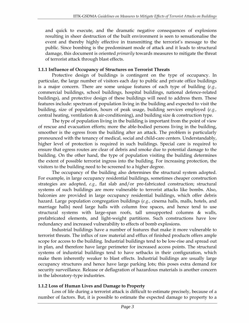
Table of Contents page
Chapter 1: Introduction 1 1.1 Hazards from Terrorism, and Consequences
1.1.1 Influence of Occupancy of Structures on Terrorist Threats 1.1.2 Loss of Human Lives and Damage to Property
1 3 4
1.2 Anti-Terrorism Strategies 4 1.3 Initial & Lifecycle Costs
1.3.1 Competing Considerations 7 8
1.4 Insurance 1.4.1 Stakeholders and their Role 1.4.2 Influence of Terrorism on Current Insurance Policies
9 10 11
1.5 Building Bye-laws for Terrorism Risk Reduction 1.5.1 Current Indian Codes Related to Terrorist Threats 1.5.2 Building Regulations
12 12 13
1.6 Risk Reduction Process 13
Chapter 2: Possible Damage to Buildings Under Blast Loading 15 2.1 Estimation of Blast Load Imposed on Buildings
2.1.1 Influence of Stand-Off Distance 2.1.2 Blast Load Prediction
15 18 21
2.2 Prediction of Blast Damage Sustained by Buildings 2.2.1 Mechanisms of Damage in Buildings
22 24
2.3 Lessons from Past Experiences 26
Chapter 3: Guidelines for New Buildings 31 3.1 Design Philosophy 31 3.2 Site Planning
3.2.1 Land-use Design 3.2.1.1 Sign Boards 3.2.1.2 Street Furniture
3.2.2 Type of Building 3.2.3 Location of Building on Plot Area
3.2.3.1 Clustering versus Spreading Buildings 3.2.3.2 Building orientation 3.2.3.3 Open space 3.2.3.4 Stand-off distance 3.2.3.5 Access roads
3.2.4 Critical Utilities of Building 3.2.5 Entry to site 3.2.6 Surveillance
3.2.6.1 Line of Sight 3.2.6.2 Entry Control 3.2.6.3 Barriers
3.2.7 Parking
32 33 33 35 35 35 35 37 38 39 41 41 43 43 43 45 46 49
3.3 Architectural Considerations 51

(xi)
3.3.1 Architectural Configuration 3.3.1.1 Shape 3.3.1.2 Size
3.3.2 Functional Planning 3.3.3 Non-structural Elements
3.3.3.1 Utilities 3.3.3.2 Window and Door Openings 3.3.3.3 Roof Systems 3.3.3.4 Exterior Wall /Cladding
51 51 53 53 55 55 59 63 64
3.4 Structural Aspects 3.4.1 Structural System and Level of Hardening
3.4.1.1 Five Virtues of Hardened Structures 3.4.1.2 Choice of Structural System
3.4.2 Progressive Collapse Analysis 3.4.2.1 Design Methods 3.4.2.2 Design Strategies
3.4.3 Improving Local Response of Structural Elements 3.4.3.1 Building Envelope Issues 3.4.3.2 Roof and Floor Slabs 3.4.3.3 Roof/Floor Beams versus Transfer Girders 3.4.3.4 Columns and Walls
64 65 65 66 66 67 68 69 69 70 73 76
3.5 Analysis and Design 79
Chapter 4: Guidelines for Existing Buildings 83 4.1 Basic Anti-terrorism Strategies for Existing Buildings 83 4.2 Mitigation Treatments for Different Hazards
4.2.1 Explosion 4.2.2 Arson 4.2.3 Armed Attack 4.2.4 Biological, Chemical, Nuclear and Radiological Attack 4.2.5 Others
83 83 84 84 84 85
4.3 Asset Value 85 4.4 Vulnerability Assessment
4.4.1 Overall Vulnerability Rating 4.4.2 Detailed Vulnerability Assessment
86 86 89
4.5 Risk Evaluation and Reduction 4.5.1 Risk Assessment 4.5.2 Risk Management
89 90 91
Chapter 5: Concluding Remarks 5.1 Summary 5.2 Challenges
5.2.1 Systemic Issues 5.2.2 Technical Issues
93 93 94 94 94
Appendix A: Blast Loading on Structures 97 References 117

Document No. :: IITK-GSDMA-TA01-V2.0 Final Report I :: D – Terrorist Attack
IITK-GSDMA Project on Building Codes
Guidelines on
Measures to Mitigate Effects of Terrorist Attacks on Buildings
by
C. V. R. Murty Department of Civil Engineering
Indian Institute of Technology Kanpur Kanpur
Indian Institute of Technology Kanpur Kanpur
July 2007

IITK-GSDMA Guidelines on Measures to Mitigate Effects of Terrorist Attacks on Buildings
Page 1
Chapter 1 Introduction
Terrorist attacks on buildings may not be eliminated completely, but the effects of these attacks on buildings and structures can be mitigated to a large extent with precautions and pre-emptive strategies. Understanding the building and its functional use, and possible threats due to terrorist attacks, is essential in identifying strategies that are most likely to be effective to prevent detrimental effects of the attacks. The cost of upgrading the building for a “certain level” of resistance against terrorist threats may not be significant as compared to the overall lifetime costs of the building (including the land value, and security monitoring). This chapter describes these aspects along with financial and techno-legal issues related to terrorism risk management. 1.1 Hazards from Terrorism, and Consequences
Broadly, terrorist attack can be classified into the following five categories:
(a) Explosion: This refers to air-borne or grounded detonation of explosive devices on or near
targets. The detonator can be carried by hand, delivered by vehicles, hurled as projectiles, or placed in the usual supplies to the building including mail. The detonators can be non-nuclear type or nuclear-type.
Explosions almost instantaneously damage the built environment. If more devices than one are used in a chain, then the duration of the threat is enhanced and the extent of damage is greater. The extent of damage is determined by the type, quality and quantity of explosive used, and the stand-off distance from the structure. Damage can vary over a spectrum of possibilities – from non-structural element loss, structural element damage, structural element collapse, to progressive failure of part/whole building.
(b) Arson:
This refers to initiation of fire at or near targets. The fire can be initiated by direct contact or by a projectile carrying an accelerant.
The threat can last from minutes to hours. The extent of damage is determined by the type and quantity of device/accelerant used in arson, and by the type of materials present at or near targets. Again, damage can vary over the whole spectrum – from non-structural element loss, structural element damage, structural element collapse, to progressive failure of part/whole building.
(c) Armed Attack:
This refers to tactical assault or sniper attacks from remote location. The attack can be by ballistics using small arms, or by stand-off weapons using rocket-propelled grenades or mortars.
The armed attack can last from minutes to days depending on how agile the counter-attack is in wearing-off and over-powering the aggressors. The extent of damage is contingent on the intent and capabilities of the attacker.

IITK-GSDMA Guidelines on Measures to Mitigate Effects of Terrorist Attacks on Buildings
Page 2
(d) Biological, Chemical, Nuclear and Radiological Attack:
This refers to contamination or dispersion of the natural or built environment that leads to harmful effects of humans and biological life. The contaminants can be solid, liquid or gaseous, and generated instantaneously at the site of attack by biological, chemical, nuclear or radiological reactions. The reactions can affect directly the body parts immediately at the instant of attack, or can lead indirectly to diseases as the reactions enter the body, food and water chains.
Biological attacks may last from hours to years, while chemical attacks last from hours to weeks. But, in both cases, the duration for which the attack has an influence is dependant on the agent employed and the conditions under which the agents are released. The biological contamination can spread through wind and water, while biological infections can spread through human and animal vectors. On the other hand, chemical contamination can be spread through persons, vehicles, water and wind; chemicals can have lasting effects, if not remediated.
Contamination due to radiological agents may last from seconds to years. Similarly, the light/heat flash and blast overpressure due to a nuclear explosion may last only for a few seconds, but the negative fall out of these radiations effects can persist for years. Electronic devices, if not protected, may also be affected by the nuclear radiation effect.
(e) Others:
There are a number of other covert acts of terrorists that impairs human life and activities. These include: cyber-terrorism (by corrupting computers or computer systems through the inter-machine protocol), agri-terrorism (by contaminating food supplies or introducing pests and/or disease agents in crops and livestock), unauthorized entry into a restricted facility (by forcing entry using the threat of weapons, breaking through doors/walls, or falsifying one’s identity), and unauthorised surveillance (by covertly collecting visual, sonic or electronic information).
Cyber-terrorism can happen in minutes to days, while agri-terrorism can take longer, say from days to months. These attacks usually do not have any effect on the built environment, but there are grave consequences at discrete locations in the form of loss of electronic data or contamination of food chains or animal farms. The duration of attack in unauthorised entry lasts from a few minutes to hours. The attack in itself causes immediate destruction of the intended facility, but the impact of this last for a much longer duration. In instances, where the intent of such an attack is on individuals, the attack can lead to fatalities, and hence permanent loss. Unauthorised surveillance is a slower attack; usually, it is conducted over months to capture detailed information on the movements and activities in a restricted space, with a view to understanding vulnerabilities of the environment. Based on this event, usually a larger explicit attack is planned on a facility or a person.
Historically, all of the above methods have been employed by anti-social elements to disrupt prevalent normalcy of life and living. With time, new types of attacks have been employed, but till date, the dominant threat mode has been through bombings. There are many reasons for this choice. Ingredients and techniques for making bombs are available easily in the open market, and it is possible to assemble bombs in a non-industrial environment. Also, bombing is easy
IITK-GSDMA Guidelines on Measures to Mitigate Effects of Terrorist Attacks on Buildings
Page 3
and quick to execute, and the dramatic negative consequences of explosions resulting in sheer destruction of the built environment is seen to sensationalise the event and thereby highly effective in transmitting the terrorist’s message to the public. Since bombing is the predominant mode of attack and it leads to structural damage, this document is oriented primarily towards measures to mitigate the threat of terrorist attack through blast effects.
1.1.1 Influence of Occupancy of Structures on Terrorist Threats
Protective design of buildings is contingent on the type of occupancy. In particular, the large number of visitors each day to public and private office buildings is a major concern. There are some unique features of each type of building (e.g., commercial buildings, school buildings, hospital buildings, national defence-related buildings), and protective design of these buildings will need to address them. These features include: spectrum of population living in the building and expected to visit the building, size of population, hours of peak usage, building services employed (e.g., central heating, ventilation & air-conditioning), and building size & construction type.
The type of population living in the building is important from the point of view of rescue and evacuation efforts; more the able-bodied persons living in the building, smoother is the egress from the building after an attack. The problem is particularly pronounced with the tenancy of medical, social and child-care centers. Understandably, higher level of protection is required in such buildings. Special care is required to ensure that egress routes are clear of debris and smoke due to potential damage to the building. On the other hand, the type of population visiting the building determines the extent of possible terrorist ingress into the building. For increasing protection, the visitors to the building need to be screened to a higher degree.
The occupancy of the building also determines the structural system adopted. For example, in large occupancy residential buildings, sometimes cheaper construction strategies are adopted, e.g., flat slab and/or pre-fabricated construction; structural systems of such buildings are more vulnerable to terrorist attacks like bombs. Also, balconies are provided in large occupancy residential buildings, which offer debris hazard. Large population congregation buildings (e.g., cinema halls, malls, hotels, and marriage halls) need large halls with column free spaces, and hence tend to use structural systems with large-span roofs, tall unsupported columns & walls, prefabricated elements, and light-weight partitions. Such constructions have low redundancy and increased vulnerability to effects of bomb explosions. Industrial buildings have a number of features that make it more vulnerable to terrorist threats. The influx of raw material and efflux of finished products offers ample scope for access to the building. Industrial buildings tend to be low-rise and spread out in plan, and therefore have large perimeter for increased access points. The structural systems of industrial buildings tend to have setbacks in their configuration, which make them inherently weaker to blast effects. Industrial buildings are usually large occupancy structures and hence have large parking lots; this poses extra demand for security surveillance. Release or deflagration of hazardous materials is another concern in the laboratory-type industries. 1.1.2 Loss of Human Lives and Damage to Property
Loss of life during a terrorist attack is difficult to estimate precisely, because of a number of factors. But, it is possible to estimate the expected damage to property to a

IITK-GSDMA Guidelines on Measures to Mitigate Effects of Terrorist Attacks on Buildings
Page 4
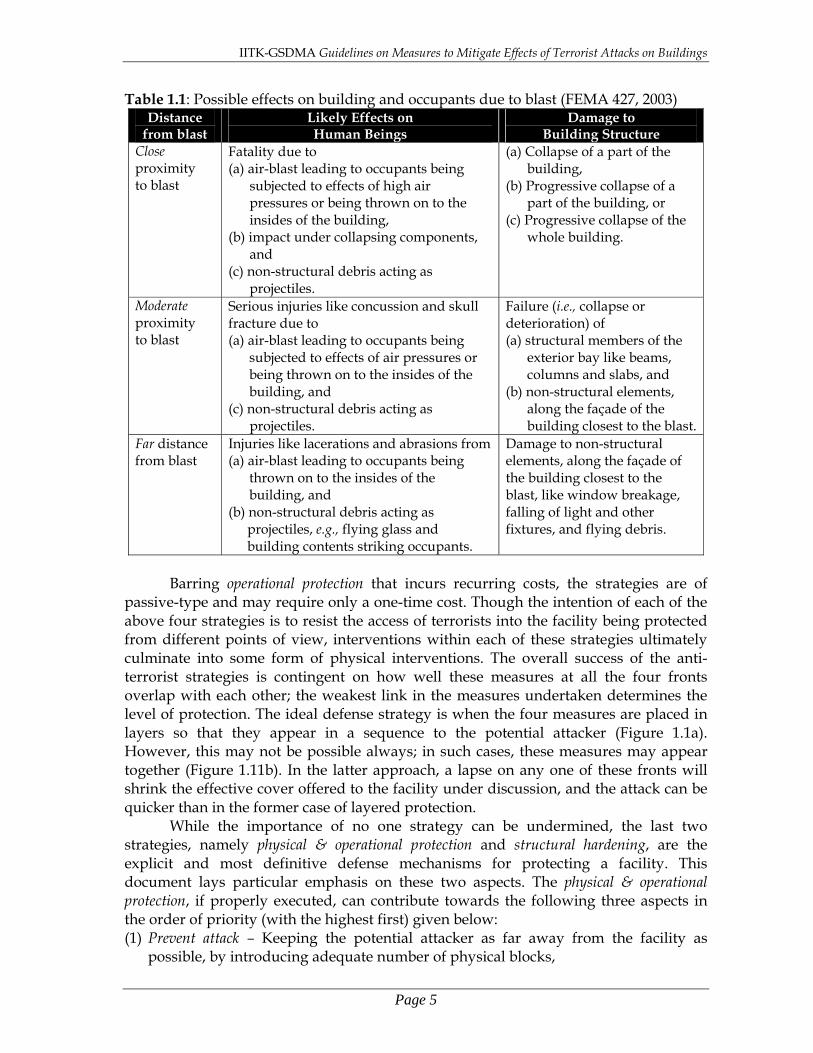
reasonable level of accuracy. However, when the threat is a bomb blast, damage due to air-blast effects may be estimable but that due to debris impact remains uncertain. But, when the building under discussion is amongst a cluster of other buildings, even estimating the damage due to blast loading may become a challenge particularly because of diffraction of the blast pressure waves by the neighbouring buildings. But, past case studies of bomb blasts show that there is strong correlation between structural damage and injury patterns (see Section 2.3). Damage to property due to a bomb blast can be classified into three groups, namely (a) collapse of the building, (b) local structural damage of a part of the building, and (c) no structural damage to the building, but significant non-structural damage in the building due to blast effects. Structural analysis based simulations provide good estimate of damages to the building, and from that the possible loss of life can be estimated using occupancy information. Thus, loss of life can be estimated in damage groups (a) and (b) above. However, in damage group (c), since the non-structural damage can be varied, it will be difficult to estimate loss of life, but upper bound numbers can still be estimated. A broad correlation between the damage to buildings and the effect on its human occupants due to a bomb blast is shown in Table 1.1. 1.2 Anti-Terrorism Strategies
Mitigating the effects of terrorist attacks is possible on four fronts, namely intelligence, deception, physical & operational protection, and structural hardening (Figure 1.1). The ideal option to fend off the potential terrorist threat is with intelligence measures; this can be done by understanding, preventing and pre-empting moves of the terrorists. The next level of defense is deception tactics, wherein (a) the facility is made to appear to be more protected or under lower-risk facility than it actually is, thereby not drawing the attention of an un-researched terrorist, or (b) the attacker is misdirected to a portion of the facility that is non-critical. The third level of preparedness considers implementing physical security measures along with on-line operational security forces in the form of surveillance, guards, and sensors; this defense mechanism is provided in layers to delay and/or thwart the attack. The final frontier of defense is structural hardening; when all the previous three measures fail to ward off the attacker, this strategy is built-in to save lives and to facilitate evacuation & rescue. This is achieved by considering the worst loading on the facility being protected, performing appropriate structural design and construction, and thereby preventing collapse of the building structure and limiting the flying debris of the non-structural elements. Notwithstanding the above discussion on the sequence in which the four strategies come into force, the above four strategies of intelligence, deception, physical & operational protection and structural hardening can be effective in a different sequence depending on the type of facility being protected and on the prevalent terrorist threat.
IITK-GSDMA Guidelines on Measures to Mitigate Effects of Terrorist Attacks on Buildings
Page 5
Table 1.1: Possible effects on building and occupants due to blast (FEMA 427, 2003) Distance
from blast Likely Effects on Human Beings
Damage to Building Structure
Close proximity to blast
Fatality due to (a) air-blast leading to occupants being
subjected to effects of high air pressures or being thrown on to the insides of the building,
(b) impact under collapsing components, and
(c) non-structural debris acting as projectiles.
(a) Collapse of a part of the building,
(b) Progressive collapse of a part of the building, or
(c) Progressive collapse of the whole building.
Moderate proximity to blast
Serious injuries like concussion and skull fracture due to (a) air-blast leading to occupants being
subjected to effects of air pressures or being thrown on to the insides of the building, and
(c) non-structural debris acting as projectiles.
Failure (i.e., collapse or deterioration) of (a) structural members of the
exterior bay like beams, columns and slabs, and
(b) non-structural elements, along the façade of the building closest to the blast.
Far distance from blast
Injuries like lacerations and abrasions from (a) air-blast leading to occupants being
thrown on to the insides of the building, and
(b) non-structural debris acting as projectiles, e.g., flying glass and building contents striking occupants.
Damage to non-structural elements, along the façade of the building closest to the blast, like window breakage, falling of light and other fixtures, and flying debris.
Barring operational protection that incurs recurring costs, the strategies are of
passive-type and may require only a one-time cost. Though the intention of each of the above four strategies is to resist the access of terrorists into the facility being protected from different points of view, interventions within each of these strategies ultimately culminate into some form of physical interventions. The overall success of the anti-terrorist strategies is contingent on how well these measures at all the four fronts overlap with each other; the weakest link in the measures undertaken determines the level of protection. The ideal defense strategy is when the four measures are placed in layers so that they appear in a sequence to the potential attacker (Figure 1.1a). However, this may not be possible always; in such cases, these measures may appear together (Figure 1.11b). In the latter approach, a lapse on any one of these fronts will shrink the effective cover offered to the facility under discussion, and the attack can be quicker than in the former case of layered protection.
While the importance of no one strategy can be undermined, the last two strategies, namely physical & operational protection and structural hardening, are the explicit and most definitive defense mechanisms for protecting a facility. This document lays particular emphasis on these two aspects. The physical & operational protection, if properly executed, can contribute towards the following three aspects in the order of priority (with the highest first) given below: (1) Prevent attack – Keeping the potential attacker as far away from the facility as
possible, by introducing adequate number of physical blocks,

IITK-GSDMA Guidelines on Measures to Mitigate Effects of Terrorist Attacks on Buildings
Page 6
(2) Delay attack – The potential access path of an attacker can be lengthened by designing landscape or architectural features, like providing buffer zones, serpentine paths and fences, thereby making it more difficult for the attacker to reach the intended target. This delay will offer additional time from the moment the attack is initiated, so that the security forces can upscale the defense or even launch a counter-attack on the terrorist.
In the physical & operational protection, since the physical and operational measures are required to work hand-in-glove, the owner and the security professionals define their requirements for the various potential threat levels in the early stages itself of the process of planning and designing the facility. Further, any facility should be optimally protected; too much of protection or no-protection at all can be counterproductive.
(a)
(b) Figure 1.1: Components of security strategies that can be undertaken, and sequences in
which they may come into force: (a) strategies in force in serial – ideal situation, and (b) strategies in force in parallel – general situation [adapted from FEMA 427, 2003].
Attack Attack
Attack Attack
Zone of Highest
Protection Intelligence
Deception
Structural Hardening
Physical & Operational Protection
Deception Intelligence Physical & Operational Protection Structural
Hardening
Attack Zone of Highest
Protection

IITK-GSDMA Guidelines on Measures to Mitigate Effects of Terrorist Attacks on Buildings
Page 7
1.3 Initial & Lifecycle Costs The cost of a facility should be seen in terms of both the initial cost as well as the
life-cycle cost. In some projects, initial cost of setting up the structure may seem low, but in the long-run, cost of maintaining and upgrading it may be high. To capture such financial burdens during the planning stage itself, life-cycle cost is relied upon to get a more meaningful reflection of the viability and sustainability of the facility.
Determining the initial cost of constructing and protecting a facility involves a number of factors. But, one factor that seems to directly affect protection cost is the stand-off distance of the facility from the un-protected access point nearest to it. All protection strategies that are affected by the level of threat, say by the amount of charge used in the explosive (in terms of equivalent tons of TNT), are seen as variable costs, implying that they depend on stand-off distance. On the other hand, protection strategies or measures that do not depend on the level of threat, e.g., the hardware required at the security surveillance control room or the space required to house the facility, are seen as fixed costs. Since designers do not have control on the level of threat, they often attempt to reduce the initial cost of the structure by increasing the stand-off distance, because the peak blast pressure is inversely proportional to the square of the stand-off distance. But, increasing the stand-off distance has the downside of increased perimeter from the facility to be protected and increased land cost. Thus, one can identify an optimal stand-off distance from the partial initial cost, which is the sum of cost of protection (i.e., hardening cost) and cost of stand-off (i.e., land cost and perimeter protection cost). The fixed costs need to be added to this partial initial cost to obtain the initial cost (Figure 1.2).
Sometimes, when the plot size is limited, designers tend to increase stand-off distance from the perimeter of the plot to accommodate the expected threat level, and decrease foot print of the structures by building vertically upwards. Increasing the number of floors increases the construction cost and also poses additional threat of increased exposure of the facility to the far neighbourhood. While it is difficult to determine exactly the contribution of each component (be it structural or non-structural measure of protection) to the initial cost (Figure 1.2), trends from the past projects in USA show that hardening of unsecured areas cost the least, followed by measures to prevent progressive collapse, and then by exterior window and wall enhancements.
Life-cycle costs are important in determining the feasibility of creating and protecting a facility. In particular, when Chemical, Biological and Radiological (CBR) threats are being addressed, the maintenance costs are high. In situations where the land is rented, the rentals may also rise disproportionately making the life-cycle costs to be more critical than the initial cost. Access control points are a drain on the maintenance cost. Sometimes, it may be economical to have fewer access points serving the same function.

IITK-GSDMA Guidelines on Measures to Mitigate Effects of Terrorist Attacks on Buildings
Page 8
Figure 1.2: Contributors to initial cost of a facility [FEMA 427, 2003]. 1.3.1 Competing Considerations
The above discussion on increasing stand-off distance for increased protection assumes a maximum credible design threat level. Under this situation, if the optimal initial cost of the facility exceeds the available budget, the facility should be designed for a reduced design threat level. However, in such case, the importance of the facility will determine whether the reduced level of protection is acceptable or not. Even if this cost is beyond the budget, the design threat level can be further reduced; in this case, the client needs to accept the increased risk. Some clients may look at individual components of protection and scale down some of the items. The owner may prioritize enhancements, based on their effectiveness in saving lives and reducing injuries. For instance, the owner may drop the laminated glass, which is perhaps the single most effective measure to reduce extensive non-fatal injuries, in favour of increased measures against progressive collapse. In another situation, say of a financial institution with trading floors, the high business interruption costs can outweigh all other concerns, and the most cost-effective solution may be to provide a redundant facility itself.

IITK-GSDMA Guidelines on Measures to Mitigate Effects of Terrorist Attacks on Buildings
Page 9
Past experiences indicate that it is difficult and more expensive to account for terrorist hazard in existing buildings and structures. Significant alterations and modifications, e.g., re-orienting functional layout, changing architectural concepts, strengthening security, and hardening the structure, may be necessary to offer the requisite protection in existing buildings. On the other hand, providing mitigation measures in new structures not only reduces the overall cost of protection, but also increases the overall protection. Early consideration of terrorist threat allows the owner to optimize the initial cost by carefully weighing the trade-offs of various options in the four mitigation strategies, namely intelligence, deception, physical & operational protection and structural hardening. Notwithstanding the prevalent fragile environment of terrorist threat in the country, it is unlikely to have mandatory design requirements instituted in design codes for all structures in the country. However, it is desirable to have at least the minimal measures for most critical buildings. Most importantly, individual owners of facilities need to decide on the consequences of terrorist attack on their facility and determine whether a detailed treatment of measures to mitigate the terrorist attack need to included or not in their structure. Notwithstanding the choice of owners, guidelines should be available in public domain to warn and guide the stakeholders to protect their facilities against terrorist attacks. 1.4 Insurance
Insurance is a mechanism of transferring risk, and thereby developing capacity in individuals to accept risks larger than what they can absorb without discontinuing their function. Property insurance has been in practice for a number of recurring hazards, like fire, theft and cyclones. Insurance has served to spread risks, and to create a database for identifying and reducing risks on the built environment. Data from past disasters has helped in understanding dominant threats and in encouraging effective mitigation measures. The incentive for successfully undertaking mitigation measures was reflected in differential premiums while purchasing insurance. Access to insurance and pricing of insurance was practiced in the past based on the risk taken by a facility, and this has been a very effective tool for strongly influencing building design and management practices in communities across the world.
In the context of the present subject, insurance for protecting buildings and structures against terrorist hazard is new to the World at large and to India in particular. The concerns include: (a) The terrorist threat is not well defined. (b) There is very limited data from past experiences of terrorist attacks on buildings
and structures. (c) There is even lesser experience of effectiveness of protective measures provided in
buildings. The insurance companies have not yet understood this new threat, as traditional means of risk analysis have been ineffective, and hence they are unable to arrive at a basis for estimating the risk and pricing the insurance. On the other hand, even the potential buyers of insurance to cover terrorism-related risk to their facility do not have a basis for estimating how much they need to insure their facility for.
Terrorism-related insurance premiums are priced based on actual evaluation of

IITK-GSDMA Guidelines on Measures to Mitigate Effects of Terrorist Attacks on Buildings
Page 10
risk, market capacity to pay and competition between insurance companies. A dominant aspect of insurance pricing is the perception of risk by both the owners and insurance companies. In the limited experiences of the past, indiscriminate pricing has led insurances companies from fleeing the market requiring government intervention to support the insurance companies. Therefore, financial policies laid down by governments on matters related to natural and man-made disasters also play an important role in building confidence amongst insurance companies to enter the market.
Terrorism risk is a cumulative effect of prevalent hazard of terrorism, exposure to terrorism, and vulnerability to effects of terrorist attacks. Vulnerability of the building to terrorist attack is an important determinant to its terrorist risk reduction. Thus, documents on guidelines to mitigate effects of terrorist attacks on structures, like the present document, are extremely valuable in educating owners of facilities, insurance companies and governments to understand terrorist risk to the existing and new structures, and providing them incentives to undertake terrorism risk reduction.
1.4.1 Stakeholders and their Role
The stakeholders in the insurance industry are (a) agents & brokers, who connect the insurance companies with the owners, with the agents on the side of the companies and the brokers on the side of the owners, (b) direct insurers, which are the insurance companies that are the front end of the industry offering insurance to the owners, and interacting with the government/government bodies to determine the insurance premiums, (c) actuaries, who are the back end of the insurance industry and the main backbone for risk evaluation and pricing, and (c) Re-insurers, which are the companies that insure the insurance companies. Each of these stakeholders contributes to communicating the realities and perceptions of risk at the field level in the process of evaluating the terrorism risk.
Agent and broker persuade the owner and direct insurer to buy and sell insurance, respectively. Direct insurer writes the policy, collects the premium and pays the claim to the insured. Direct insurer has the responsibility to determine the premium based on terrorism risk analysis, and discuss with the insurance regulatory authority of the jurisdiction. They have a good idea of the terrorism risk at the national level. Actuaries study the risk and better inform the direct insurers and re-insurers of the threats of the hazard. Re-insurer covers some of the possible liability of the direct insurer. Re-insurer operates at a global level and transfers part of risk to other countries. In general, since the actuaries lack experience in the subject and hence unable to assess the terrorism risk with confidence, there are no regulations in the country yet mandating direct insurers to provide insurance against terrorist attack, or mandating the re-insurer to cover the direct insurer. Internationally, the World Trade Center attack on 11 September 2001 created a panic in the insurance industry. While regulations were enforced to mandate direct insurers in USA to provide insurance to cover terrorism risk, the re-insurers are yet to cover terrorism risk.
1.4.2 Influence of Terrorism on Current Insurance Policies
Currently, the insurance industry offers insurance to cover (a) property, liability, and business interruption, (b) workers' compensation, (c) health of individuals, and health maintenance organizations, and (d) life. Terrorism influences most of these

IITK-GSDMA Guidelines on Measures to Mitigate Effects of Terrorist Attacks on Buildings
Page 11
insurance lines, either directly or indirectly (Figure 1.2). In particular, the most significant influence is on business interruption. However, physical damage may not occur to buildings due to terrorist attacks other than blast and arson. Based on the 2001 World Trade Center incident, direct insurers are considering reducing liability by not insuring too many properties in a single cluster, too many individuals in the same facility, or even too many insurance lines in the same building. Table 1.2: Relationship of terrorism on particular insurance lines [FEMA 429, 2003]
Type of Terrorist Threat or Attack
Property / Liability
Business Interruption
Workers’ Compensation
Health Life
Armed Attack Probable Potential Potential Probable Arson/ Incendiary Probable Probable Potential Probable
Biological Agent Potential Probable Probable Potential Probable Chemical Agent Potential Probable Probable Potential Probable Conventional Bomb Probable Probable Probable Potential Probable
Cyber Terrorism Probable Hazardous Material Release Potential Probable Probable Potential Potential
Nuclear Device Probable Probable Probable Potential Probable Radiological Agent Potential Probable Probable Probable Probable
Surveillance Probable Unauthorised Entry Probable
The early efforts to develop loss estimation due to effects of terrorist attacks are based on loss estimation models developed for natural hazards, like earthquakes and cyclones. But, that approach has one major bottle-neck; there is no definition of the phenomenon of terrorist attack and there is no data to describe the occurrence and severity of similar events in the past centuries of years. However, efforts are underway to develop analytical simulations that study an urban region to understand the various aspects, including impact of (b) various weapons, and (b) an attack on a building on its adjacent structures. The outcome of such scenario studies should help direct insurers and re-insurers to develop a meaningful basis for pricing insurance. However, the current projection of possible scenarios is considered incomplete and hence the results of the simulations are not relied upon with high confidence level. The insurance industry will benefit from the development of guidelines, such as this document, as it will give it a baseline for determination of liability related to terrorist attacks. 1.5 Building Bye-laws for Terrorism Risk Reduction Traditionally, building safety focused on hazards like fire, natural disasters (floods, earthquakes, windstorms, snow storms) and some man-made risks (hazardous material storage). For these hazards, regulations are available covering aspects of planning, design, construction, maintenance and quality control of the structures. However, after the attack on the World Trade Center on 11 September 2001, protection of civilian population from acts of terrorism has become a major national priority and
IITK-GSDMA Guidelines on Measures to Mitigate Effects of Terrorist Attacks on Buildings
Page 12
intentional attack is also seen as one of the building hazards. Buildings bye-laws in the USA have been changed to include the same. Recommendatory design guidelines to mitigate the effects of terrorist attack on buildings in India can be developed relatively easily and quickly. However, mandatory design standards will take much longer to be developed because of a number of reasons. These include: (a) shortage of information on the potential attacks, and weapons used, (b) limited understanding of the damages associated with each of these attacks with different weapons, (c) lack of data on consequences of the damages, (d) inexperience of communities to articulate the risk to different stakeholders, and (e) no results from cost-benefit analysis studies performed for various scenarios. Codes are a result of a complex compromise or balance between the diverse commercial and social priorities to reduce the cost of construction on the one hand, and the substantive technical requirements to protect the facilities on the other. Development of codes is a result of a consensus process that can be time consuming. Eventually when such regulations are developed, they are likely to consist of requirements related to (a) zoning of the neighbourhood, (b) site planning, (c) architectural aspects, (d) structural analysis and design, (e) construction quality control and supervision, and (f) maintenance regimes. The aspects related to site planning, architectural aspects, and structural analysis & design are dealt with in detail in this document. 1.5.1 Current Indian Codes Related to Terrorist Threats
Blast loading is one of the dominant loads imposed by effects of terrorist attacks on structures. Criteria for design of structures to resist effects due to blast above ground are given in IS:4991-1968. This standard provides (a) definition of blast for different amounts of charge, (b) description of overpressures on buildings with different geometries and openings, (c) simplified analysis method assuming the building to be a single-degree-of-freedom system with elastic/elasto-plastic material behaviour, and (d) design stress values for different materials (structural steel, reinforced concrete, plain concrete and masonry) and for soils under the foundation.
Blast loading demands large lateral resistance from the building. Hence, measures to provide earthquake-resistance in buildings (through lateral strength, stiffness and ductility) are also beneficial in resisting blast loads. These issues are covered through the Indian seismic code IS:1893(1)-2002, ductile detailing code for RC structures IS:13920-1993, and earthquake resistant construction guidelines IS:4326-1993. Similarly, provisions are also available for resisting wind effects on structures, particularly due to cyclones, and fire-resistant design of structures.
However, progressive collapse is not dealt with in the Indian codes, including in the Indian seismic codes. Since, this forms the core issue in structural hardening, research studies need to be undertaken with a view to developing guidelines for the inclusion in the Indian Standards. Similarly, provisions are also required for the design of fenestrations to resist effects of blast (e.g., glass windows), and for the effects of ammunition impact on buildings and structures due to armed attack. Further, there are codes dealing with the subjects of HVAC (i.e., heating, ventilation, and air-conditioning). But, details as relevant to chemical, biological, and radiological agents being introduced into the HVAC system by terrorist are not dealt with in these codes.

IITK-GSDMA Guidelines on Measures to Mitigate Effects of Terrorist Attacks on Buildings
Page 13
1.5.2 Building Regulations No document is available in public domain related to terrorism-risk and
published by any governmental department or agency in India. However, a number of publications are available in the public domain and published by US agencies; these are listed in different chapters of this document.
Measures to mitigate effects of terrorist attacks on buildings can be implemented through building regulations that are enforced at the Union, State and local government levels, and that are encouraged through model codes and guidelines for voluntary adoption. These building regulations related to physical aspects of terrorism risk can be grouped under the following categories, namely zoning, building design, building construction, building maintenance, and building rehabilitation. Changes to bring into force building regulations in each of these categories must be carefully analyzed for political acceptability and availability of resources. Development of codes and standards to deal with terrorism risk in both new and existing buildings will require broad acceptance of the risk, understanding of the effectiveness of mitigation measures, and the assessment of societal cost-benefit ratios. 1.6 Risk Reduction Process Whether the building is new or an existing, the formal process for risk reduction involves five steps. These steps and the tasks to be undertaken within each of these steps are given below: Step 1: Threat identification and rating
(Identify threats; collect information; determining design basis threat; determine threat rating)
Step 2: Asset value assessment (Identify possible layers of defense; identify critical assets; identify building core functions and infrastructure; determine asset value rating)
Step 3: Vulnerability assessment (Organise resources to prepare the assessment; evaluate the site and building; preparing a vulnerability portfolio; determining vulnerability rating)
Step 4: Risk assessment (Prepare risk assessment charts; determine risk ratings; prioritise building components)
Step 5: Mitigation options (Identify preliminary mitigation options; review mitigation options based on cost estimates; reviewing mitigation, cost, and layers of defense)
Clearly, the process of risk reduction is comprehensive and requires a holistic approach. Each of the steps and tasks listed above will be discussed in detail in this document.

IITK-GSDMA Guidelines on Measures to Mitigate Effects of Terrorist Attacks on Buildings
Page 15
Chapter 2 Possible Damage to Buildings
Under Blast Loading
In general, bomb blasts irrespective of their origin (chemical, biological, radiological or nuclear) cause the same demand, namely large overpressure in the surrounding air beyond the normal atmospheric pressure (Figure 2.1). However, the biological and radiological blasts have implications of additional demands on the surrounding environment in terms of biological attack or radiation excess, which also are released in the course of such blasts. This chapter describes the impact of the large overpressures created by the blast on buildings. Details of blast pressure wave fronts and other engineering aspects of blast loading on structures are presented in Appendix A; a brief treatment of the same is presented in section 2.1.
Figure 2.1: Schematic of vehicle-based weapon blast indicating threat parameters and
definitions (FEMA 427, 2003). 2.1 Estimation of Blast Load Imposed on Buildings
When an explosion takes place, an exothermic chemical reaction occurs in a period of few milliseconds. The explosive material (in either solid or liquid form) is converted to very hot, dense, high-pressure gas. This highly compressed air, traveling radially outward from the source at supersonic velocities is called the shock wave front. It expands at very high speeds and eventually reaches equilibrium with the surrounding air. Usually, only about one-third of the chemical energy available in explosives is released in the detonation process; the remaining two-thirds energy is released relatively slowly as the detonation products mix with air and burn. While this process of burning has little effect on the initial blast wave because of its delayed occurrence than the original detonation, it can influence the later stages of the blast wave,

IITK-GSDMA Guidelines on Measures to Mitigate Effects of Terrorist Attacks on Buildings
Page 16
particularly in explosions in confined spaces. As the shock wave expands, pressure decreases rapidly with distance D (as 1/D3)
because of spherical divergence and dissipation of energy in heating the air. Also, pressure decays rapidly over time (as exponential function), typically in milliseconds. Thus, a blast causes an almost instantaneous rise in air pressure from atmospheric pressure to a large overpressure. As the shock front expands, the pressure drops but becomes negative. Usually, this negative pressure is sustained for duration longer than the positive pressure (Figure 2.2), and is less important in design of structures than the positive phase.
When this high-pressure shock front strikes a surface (be it ground or structure) at an angle, it is reflected producing an increase in the pressure of the air. The pressure of air in the reflected front is greater than that in the incident front, even at the same distance from the explosion. The reflected pressure varies with the angle of incidence of the shock wave – a maximum when it impinges normal to the surface and a minimum when it passes parallel to it. In addition, the reflected pressure is dependent on the incident pressure, which in turn is a function of the net explosive weight and distance from the detonation (Figure 2.3). The ratio of the peak reflected pressure Pr and the peak incident pressure Pi, called the reflected pressure coefficient, can be as much as 13. Further, for all explosions, the reflected pressure coefficients are significantly greater closer to the explosion.
Figure 2.2: Shock Front Characteristics: Overpressure-time history indicating sharp initial
drop and extended negative phase (FEMA 426, 2003)

IITK-GSDMA Guidelines on Measures to Mitigate Effects of Terrorist Attacks on Buildings
Page 17
Figure 2.3: Reflected Shock Front Characteristics: Influence of angle of incidence of shock
front and pressure of incident shock (FEMA 426, 2003)
The magnitude and distribution of the blast loading effectively acting on a structure vary greatly with (a) properties of explosive (type of material, quantity of explosive and energy output), (b) Location of detonation relative to the structure, and (c) reflections of shock front on the ground and structure. The damage in a building depends on the energy imparted to it through the reflected shock front of explosion, which is contributed by both the positive and negative phases of the pressure-time history (Figure 2.4). The pressure and hence forces on the building vary in time and space over the exposed surface of the building, depending on the location of the detonation in relation to the building. Therefore, when studying the response of a structure under a specific blast, the location of detonation which produces the most severe effects on the structure should be identified.

IITK-GSDMA Guidelines on Measures to Mitigate Effects of Terrorist Attacks on Buildings
Page 18
Figure 2.4: Energy Imparted to a Building: Time history of the impulse imparted by the
reflected shock wave (FEMA 426, 2003)
Blast effects are distinctly different from other hazards, like earthquakes, winds, or wave. The following are some of the distinguishing features: 1. The blast pressures generated on a targeted building can be several orders of
magnitude greater than those generated by wind or wave. For example, the peak incident pressure on a building in an urban setting can be larger than 8 MPa, due to a vehicle weapon parked along its curb. At such pressures, major damages and failure are expected in the building.
2. Explosive pressures decay extremely rapidly with distance from the source. Therefore, damages on the side of the building facing the explosion may be significantly more severe than those on the other sides. Hence, air blasts tend to cause localized damage. When the building is surrounded by other buildings as in an urban setting, reflections off surrounding buildings can cause increased damages even on the back side of the building.
3. The duration of the blast shock front is of the order of milliseconds. This is in contrast to the duration of loading of seconds during earthquakes, and of hours during wind or flood. As a result of this, the mass of the structure has a strong mitigating effect on the building response. This is in contrast to the situations in earthquakes, wherein larger mass can induce increased inertia forces, which can worsen the damage.
2.1.1 Influence of Stand-Off Distance
The geometric distribution of energy in the almost hemi-spherical space around the blast that occurs at or slightly above ground, suggests that the intensity of blast rapidly reduces with distance. Thus, the damage is also correspondingly smaller, which in turn implies that the amount of hardening necessary to provide the required protection reduces. Hence, the cost of providing mitigating measures reduces with

IITK-GSDMA Guidelines on Measures to Mitigate Effects of Terrorist Attacks on Buildings
Page 19
distance (Figure 2.5). For example, in the 25 June 1996 Khobar Towers Complex bombing incident in Dhahran, Saudi Arabia, the damage and hazard to occupant reduced as the stand-off distance increased from 27m (80 feet) to 133m (400 feet) (Figure 2.6). On the other hand, higher stand-off distance implies the need for larger area of land around the building. This means a longer perimeter of the plot to be secured with barriers, thereby increasing the threat and cost of mitigation measures. This is in contrast to the reduced cost with distance that is not reflected in Figures 2.5 and 2.6.
Figure 2.5: Effect of stand-off distance on cost of providing mitigation measures (FEMA
426, 2003)
In the design of buildings, the critical location at which the blast weapon must be considered is a function of site, building layout and security measures in place. The critical locations for external weapons (i.e., bombs in vehicle) are the closest points that a vehicle can approach the building on each of the sides of the perimeter, assuming that all security measures are in place. These locations are typically where a vehicle can be parked along the curb directly outside the building, or at the entry control points where security checking takes place. The critical location for internal weapons (i.e., bombs placed in containers) is governed by the location of publicly accessible areas in the building, e.g., lobbies, corridors, auditoriums, cafeterias or gymnasiums. The stand-off distance is measured from the center of gravity of the explosive located in a vehicle or container, to the building under consideration.
However, estimating appropriate stand-off distances for a building, at which explosive blast effects can be safely resisted, is difficult. For buildings located in urban areas, it is either not possible or not practical to obtain appropriate stand-off distance. An additional constraint is predicting the weight of the explosive. In effect, there is a rare chance of doing this even reasonably. Thus, the Department of Defense of USA prescribes minimum stand-off distances based on the required level of protection that can be provided: (a) when minimum stand-off distances can be met with, conventional design & construction techniques can be used with some modifications; but (b) when minimum stand-off distances cannot be met with, the building must be hardened to achieve the required level of protection (UFC4, 2002). On the other hand, the American Security Criteria (GSA and ISC) neither require nor mandate specific stand-off

IITK-GSDMA Guidelines on Measures to Mitigate Effects of Terrorist Attacks on Buildings
Page 20
distances. Instead, protection performance criteria are provided. To economically meet these performance standards, recommended stand-off distances are presented for vehicles parked on adjacent properties and for vehicles parked on the building site (GSA, 2001; ISC, 2001). The extent of building damage is determined by this important parameter, the stand-off distance. This parameter is extensively used in the design of structures against blast. Two effects are determined by stand-off distance, namely (a) overpressure in the surrounding air, and (b) level of damage to various components and structural systems of buildings. The preceding sections in this chapter established that the overpressure due to a blast is critically dependant on the distance from the blast; the larger is the distance from the blast, the better it is from the point of vulnerability of the structure (Figure 2.7). Therefore, stand-off distance, the clear distance between the location of a potential explosion and the structure in focus, is very important.

IITK-GSDMA Guidelines on Measures to Mitigate Effects of Terrorist Attacks on Buildings
Page 21
Figure 2.6: Results of computer simulations of effect of stand-off distance on damage to
buildings in Khobar Towers site, Dhahran, Saudi Arabia, during the 26 June 196 bombing (FEMA 426, 2003)
Figure 2.7: Stand-Off distances: Overpressures generated with distance due to blasts of
different yields (FEMA 427, 2003) 2.1.2 Blast Load Prediction
To study the effect of blast on structures, first the blast loads on the structure need to be predicted. For exterior detonation, the blast pressure causes damage to the building. Since the pressure over the exterior surface of the building varies with stand-off distance, angle of incidence, and reflected pressure, blast loads should be predicted for multiple threat locations of the detonation and the worse case conditions used in design.
In most cases, especially for design of single and isolated buildings, simplified methods are used by consultants to predict blast loads. The overpressure is assumed to instantaneously rise to its peak value and decay linearly to zero in a time known as the duration time tD. Designers use pre-prepared tables (GSA, 2001) or charts, such as the one shown in Figure 2.7. The figure provides a quick method for predicting the expected overpressure on a building for a specific explosive weight and stand-off

IITK-GSDMA Guidelines on Measures to Mitigate Effects of Terrorist Attacks on Buildings
Page 22
distance. Alternately, simplified computer programs that consider overtly simplified situations like a planar blast analysis can be used (e.g., ATBLAST of the US General Securities Administration, and CONWEP of the US Army Engineer Research and Development Center).
However, in the design of complex structures, refined estimates of blast load on the structure are required. Some blast design consultants use methods of analysis like Computational Fluid Dynamics (CFD); these are sophisticated and require special equipment & skills. 2.2 Prediction of Blast Damage Sustained by Buildings For an identified potential threat from bombs of different sizes, the demand blast pressure on the buildings can be estimated as discussed in section 2.1. The second half of the task is to understand whether this demand can be resisted safely by the building. The possible range of damage due to the imposed demand pressure-time history must be studied to evaluate the adequacy of the hardness provided in the building. Past experiences suggest that the extent and severity of damage in a building cannot be predicted accurately and with certainty. The damaged structure undergoes nonlinear inelastic behaviour the nonlinear response at any instance of time is sensitive to small variations in input loading as well as the immediately past inelastic response sustained by the structure until that time instance. Despite these uncertainties, some general indicative trends of overall damage can be ascertained, based on size of explosion, stand-off distance and assumptions about construction of building.
Damage levels may be estimated by field testing, nonlinear structural analysis, or both. Testing is an active option for government agencies and (with permission) for private agencies that develop specialized products related to mitigation measures. Often, these explosive test programs are adopted to verify effectiveness of small products and not for large facilities like buildings. Since buildings are unique and too expensive, testing is an unlikely option for buildings that are yet to be built. Thus, designers resort to detailed structural analysis instead. For greater reliability of these analyses results, the analyses must account for both time-dependent effects of the explosive event and nonlinear behavior of the building. Such advanced analytical tools are already in use in seismic design particularly of special and critical structures, like dams and nuclear power plants.
The analytical models employed for blast analysis of buildings range from equivalent single-degree-of-freedom (SDOF) systems to detailed finite element (FEM) representations. As the level of sophistication of the analytical model increases, more complicated failure modes can be captured. Irrespective of the type of model employed, since blast loading is of short-duration and response is nonlinear, the numerical computations are required to be performed with adequate resolution in space and time. Some examples of such computer programs in use are AT Planner (of US Army Engineer Research and Development Center), BEEM (of US Technical Support Working Group) and BLASTFX (of US Federal Aviation Administration). While selection of appropriate analytical model to capture all significant failure modes is the first challenge, the interpretation of the results of these detailed analyses is the second one. Thus, whenever possible, analytical results should be cross-verified against those from testing and/or experiments on similar buildings under similar loadings.

IITK-GSDMA Guidelines on Measures to Mitigate Effects of Terrorist Attacks on Buildings
Page 23
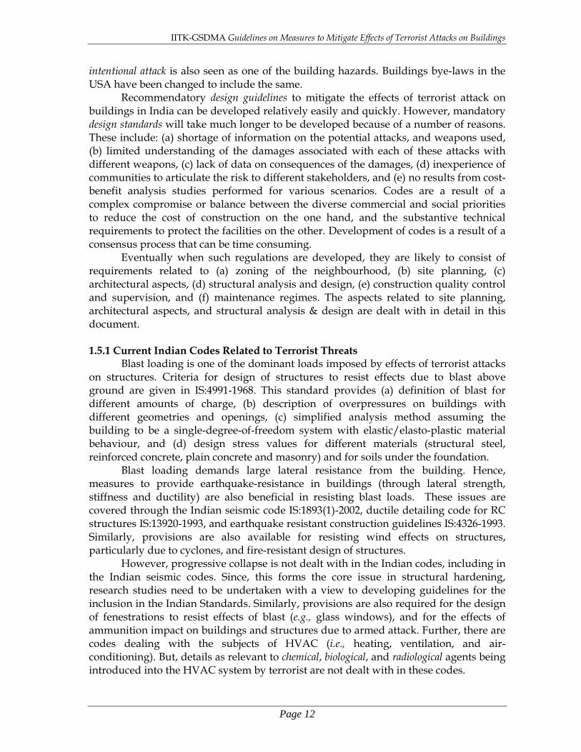
Clearly both testing and analysis of the full-scale building requires large amounts of time, financial inputs and technical skills. Moreover, since the design process is iterative, a trade-off is necessary between the cost of analysis and the level of confidence in the results. Often, an easier approach taken by designers is through testing/analysis building components. For example, beams, slabs and walls are modeled with simple idealizations like SDOF systems, and their response is evaluated. These responses are then presented in the form of charts (e.g., Figure 2.8) or tables (e.g., Table 2.1). Such charts are extremely useful in preliminary design, while the more sophisticated techniques are employed in the final design. Important conclusions can be drawn even from these preliminary design tools like charts and tables. For example, Figure 2.8 can be useful in the following way: While bombs carried in hand bags tend to be small, those housed in vehicles are bigger and stronger. Thus, they would have a large radius of influence. While hand-carried bombs raise a serious need for security screening of persons entering the building, vehicle-mounted bombs are important in planning the proximity of parking areas to the building.
Figure 2.8: Stand-Off distances: Damage to various building features varying with
distance due to blasts of different yields (FEMA 427, 2003)
IITK-GSDMA Guidelines on Measures to Mitigate Effects of Terrorist Attacks on Buildings
Page 24
Table 2.1: Estimates of incident pressures at which damage may occur in different building components (FEMA 426, 2003)
2.2.1 Mechanisms of Damage in Buildings
Shock wave front caused by explosions cause two types of damage, namely (a) Local Damage: The direct action of the high-intensity air-blast on the exposed
surfaces of the building causes damage to individual non-structural and structural components of the building (e.g., non-structural elements like exterior infill walls and windows, and structural elements like floor systems (slab and girders), columns and load-bearing/structural walls). The building is still intact; and
(b) Global Damage due to Progressive collapse: The collapse of a single structural element or few structural elements at a local level may result in a domino effect and lead to progressive collapse of a part or the whole building.
Local damage is the primary damage mechanism under blast loading. Buildings are designed usually for loads that are several orders of magnitude smaller than that imposed by the blast overpressures and reflection effects. Also, the blast-induced loading may be even in directions along which the building has not been designed, e.g., upward loading on floors. The blast pressure acts on the exterior envelope of the building, and then enters the buildings first by damaging the weakest element. For instance, the blast pushes on the exterior infill walls and windows at the lower storeys, and fails the walls and breaks the windows. Then, the shock wave enters the building, continues to expand, and pushes both upward and downward on floors (Figure 2.9). Local damage occurs within 10-100 milliseconds from the time of detonation. Also, the building is engulfed by the shock wave within a similar time-frame. Glass is the weakest component of a building. It breaks at low pressures compared to other structural components, and its fragments become high-velocity projectiles leading to major injuries; in some instances of large blasts, the debris may spread over kilometers.

IITK-GSDMA Guidelines on Measures to Mitigate Effects of Terrorist Attacks on Buildings
Page 25
Figure 2.9: Schematic showing sequence of building damage due to a vehicle weapon
from local damage to global damage due to progressive collapse (FEMA 427, 2003) When large-yield vehicle-delivered explosions occur, floor slabs are the most
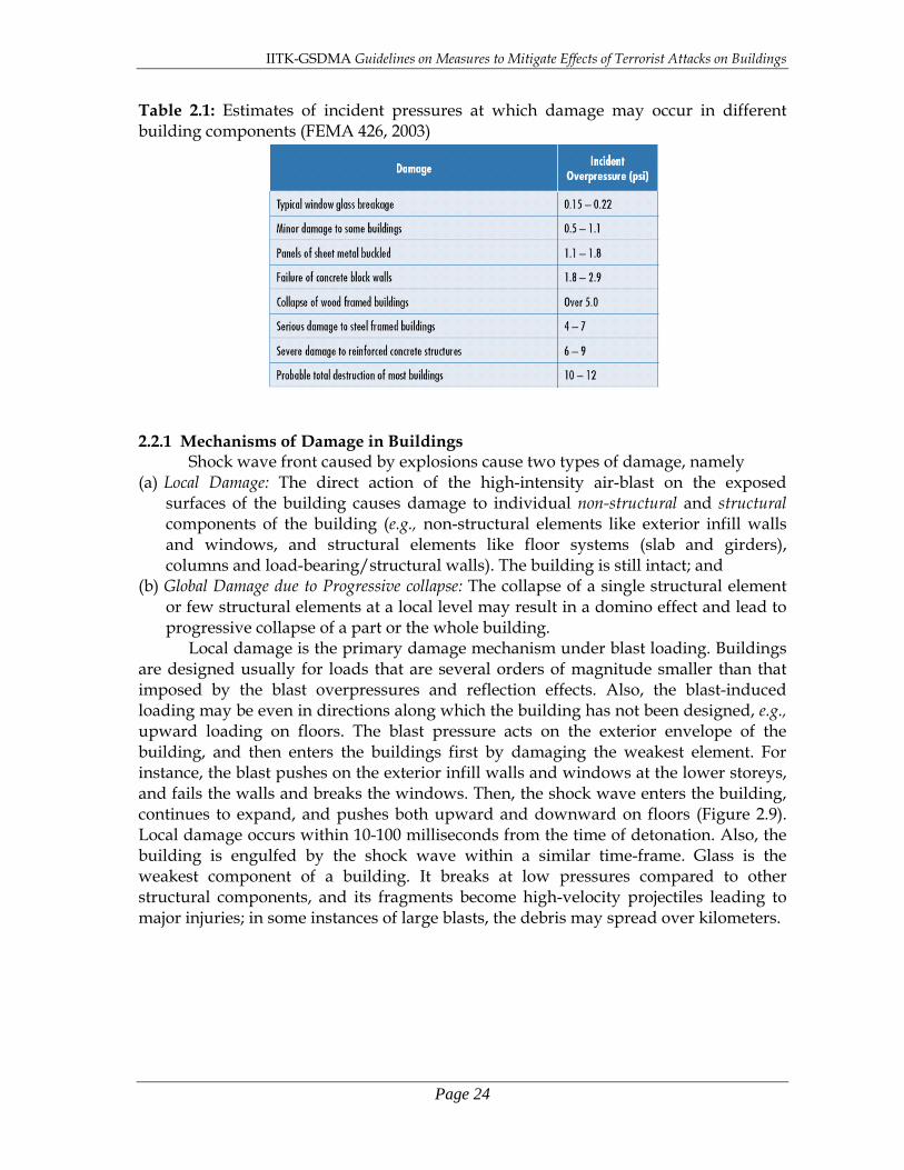
commonly the elements to be damaged, because they typically offer large exposed surface area and relatively small thickness. Floor slab failures are also common when the explosion is set-off internally. When floor slab systems fail, un-braced heights of supporting columns increase; this implies increased instability of those columns and hence of the building. When small hand-carried explosives are set off on floor slabs away from a primary vertical load-bearing element, local damage occurs along with injuries in the adjoining bays in each direction. In such internal explosions, even if the explosive is small, multiple reflections of the pressure wave front occur on the interior surfaces and hence the blast effects are amplified (Figure 2.10). The damages associated with a small internal explosion in the building include: (a) local damage and failure of floor systems immediately below & above the explosion, and of adjoining walls (both RC and masonry); (b) damage and failure of nonstructural elements (e.g., partition walls, false ceilings, ducts and window finishes); and (c) flying debris generated by furniture, computers and other contents. Severe damage, possibly leading to progressive collapse, may occur even with small internal explosions provided the explosive is placed directly at a primary load-bearing element such as a structural wall.
IITK-GSDMA Guidelines on Measures to Mitigate Effects of Terrorist Attacks on Buildings
Page 26
(a) (b) (c) Figure 2.10: Schematic showing sequence of building damage due to an internal blast
within a building: (a) local damage of floor, (b) uplift of floor above, and failure of walls and windows, and (c) venting of pressured air through the various levels of the building (FEMA 427, 2003)
Progressive collapse is said to occur when the local failure of one structural
element results in redistribution of loads to another element, which in turn fails, and so on (Figure 2.9). This eventually may result in disproportionately large collapse (partial or full) relative to the zone of initial local damage. The progression of localized damage depends on the design and construction of the building. Progressive collapse usually occurs when the blast occurs at or close to a critical load-bearing structural element. The direction of progression can be vertically upward/downward or even laterally from the source of the explosion. If initiated, progressive collapse typically occurs within seconds. 2.3 Lessons from Past Experiences
Valuable lessons are learnt from the bombing events of the past. Extent of human loss and types of injuries to habitants of the neighbourhood buildings during a blast is dependant on the type of structural damage. The following are some examples of the same: 1. The high pressure of air created can puncture eardrums and blast open lungs. 2. The high pressure can shatter window glass panes & other contents, and set them
airborne; these in turn penetrate and/or lacerate the human body. If the fragments are larger, the injury to human body can be due to impact itself. When the blast is of a very high order, persons may be thrown into all directions – on to the interior of the building or out of the building. For example, in the 1995 bombing of the Alfred P. Murrah Federal Building in Oklahoma City, shattered glass was responsible for injuries to 40% survivors. In the adjoining buildings, 25-30% injuries were due to lacerations.
3. Building collapse is the most severe reason for possible fatalities. In the Oklahoma City bombing (Figure 2.11), bodies of ~90% of the dead were recovered from the collapsed portion of the building, and many survivors in the collapsed region were trapped in void spaces under concrete slabs in the lower floors.
IITK-GSDMA Guidelines on Measures to Mitigate Effects of Terrorist Attacks on Buildings
Page 27
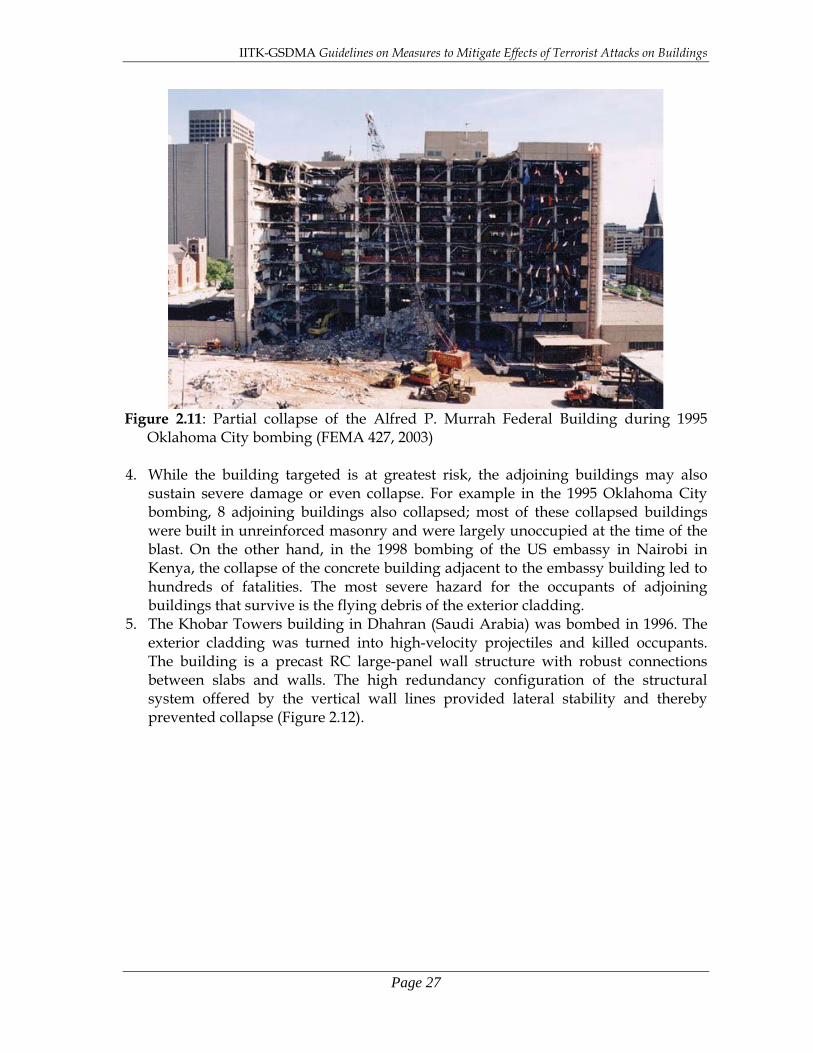
Figure 2.11: Partial collapse of the Alfred P. Murrah Federal Building during 1995
Oklahoma City bombing (FEMA 427, 2003) 4. While the building targeted is at greatest risk, the adjoining buildings may also
sustain severe damage or even collapse. For example in the 1995 Oklahoma City bombing, 8 adjoining buildings also collapsed; most of these collapsed buildings were built in unreinforced masonry and were largely unoccupied at the time of the blast. On the other hand, in the 1998 bombing of the US embassy in Nairobi in Kenya, the collapse of the concrete building adjacent to the embassy building led to hundreds of fatalities. The most severe hazard for the occupants of adjoining buildings that survive is the flying debris of the exterior cladding.
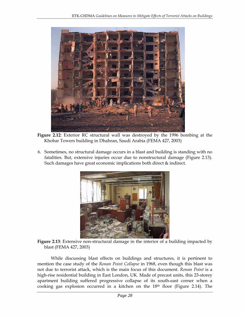
5. The Khobar Towers building in Dhahran (Saudi Arabia) was bombed in 1996. The exterior cladding was turned into high-velocity projectiles and killed occupants. The building is a precast RC large-panel wall structure with robust connections between slabs and walls. The high redundancy configuration of the structural system offered by the vertical wall lines provided lateral stability and thereby prevented collapse (Figure 2.12).
IITK-GSDMA Guidelines on Measures to Mitigate Effects of Terrorist Attacks on Buildings
Page 28
Figure 2.12: Exterior RC structural wall was destroyed by the 1996 bombing at the
Khobar Towers building in Dhahran, Saudi Arabia (FEMA 427, 2003)
6. Sometimes, no structural damage occurs in a blast and building is standing with no fatalities. But, extensive injuries occur due to nonstructural damage (Figure 2.13). Such damages have great economic implications both direct & indirect.
Figure 2.13: Extensive non-structural damage in the interior of a building impacted by
blast (FEMA 427, 2003)
While discussing blast effects on buildings and structures, it is pertinent to mention the case study of the Ronan Point Collapse in 1968, even though this blast was not due to terrorist attack, which is the main focus of this document. Ronan Point is a high-rise residential building in East London, UK. Made of precast units, this 23-storey apartment building suffered progressive collapse of its south-east corner when a cooking gas explosion occurred in a kitchen on the 18th floor (Figure 2.14). The

IITK-GSDMA Guidelines on Measures to Mitigate Effects of Terrorist Attacks on Buildings
Page 29
explosion caused the collapse of all slabs in that corner bay below and above the 18th floor in a progressive manner. This case study is important because it led to extensive research in USA, UK and Europe on progressive or disproportionate collapse, culminating into milestone changes in design codes, and in the way designers were viewing structural design of tall buildings. Research studies following this collapse led Britain to develop implicit design requirements to resist progressive collapse in buildings, and, in the 1970s, the USA to produce reports on this subject to help practicing engineers recognize this concern and address it in design of tall buildings.
Figure 2.14: Schematic of vehicle-based weapon blast indicating threat parameters and
definitions (SCI, 2004).

IITK-GSDMA Guidelines on Measures to Mitigate Effects of Terrorist Attacks on Buildings
Page 30
This page is intentionally left blank.

IITK-GSDMA Guidelines on Measures to Mitigate Effects of Terrorist Attacks on Buildings
Page 31
Chapter 3 Guidelines for New Buildings
Planning and designing of a new building considering measures to mitigate effects of terrorist attacks on buildings can lead to a very different building than that developed without considering them. Also, many of the mitigation measures are relatively inexpensive and can be easily implemented if incorporated in the early stages of design process. Thus, it is best to include these measures in new buildings from the planning stage itself, rather than include them after the building is built. This chapter describes the various considerations that need to be made while developing new buildings; these include planning, analysis, design and security of new buildings.
3.1 Design Philosophy The owner, real-estate developer, town planner, landscape designer, building
planner, architect, interior designer, structural designer and user together constitute the design community of a building. This community must strive to achieve in their design of the building the four strategies of anti-terrorism described in Chapter 1, namely increased net of intelligence, appropriate amount of deception, constant level of physical & operational protection, and adequately hardened structure. While the owner, real-estate developer and user can only articulate their needs and threats related to their building, the success of the measures to mitigate terrorist attacks is critically contingent on thorough planning, coordination and incorporation of relevant technical aspects in design by each of the other players in the design community mentioned above. Resisting terrorism and security threats, and thereby offering protection of life, property and operations, becomes the main objective. Thus, a comprehensive assessment should be undertaken of the manmade threats and hazards, which becomes a crucial input to the planning and design effort, which culminated into countermeasures for possible terrorism, and mitigation measures for coping the unfortunate event of an attack with minimal cost. This is seen as an appropriate and effective philosophy in the reduction of vulnerability and risk due to terrorist attacks.
The mitigation measures at any level are most effective only when the mitigation measures at the previous level are completely and successfully implemented. For instance, only when anti-terrorism measures under site-planning are completely addressed, that measures under building planning will be effective (Figure 3.1). Thus, the design philosophy is to make the sieve of deterrence and protection finer, thereby making it extremely difficult for (a) terrorists to penetrate further deep into the facility, and (b) terrorist attacks to be implemented. Hence, implementation of all mitigation measures originally conceived in design is mandatory for successful anti-terrorism safety of buildings.
The space between the possible blast location and the interior of the building can be demarcated into three zones (Figure 3.1), namely (a) buffer zone where blast loading effects dominate, (b) unsecured areas of the building where structural (and non-structural) damage may be expected, and (c) secured areas of the building where damage is not expected. If differential design approach is to be adopted, the unsecured areas on the blast side of the building need to be provided with higher hardness to resist the worst
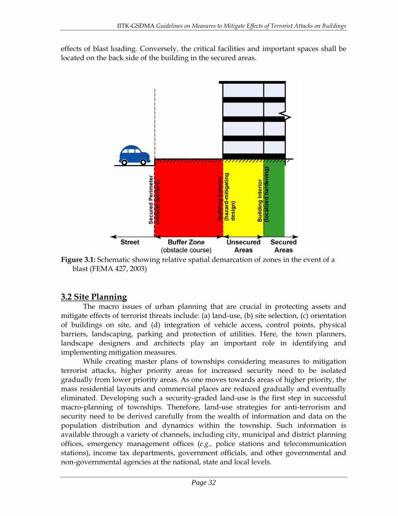
IITK-GSDMA Guidelines on Measures to Mitigate Effects of Terrorist Attacks on Buildings
Page 32
effects of blast loading. Conversely, the critical facilities and important spaces shall be located on the back side of the building in the secured areas.
Figure 3.1: Schematic showing relative spatial demarcation of zones in the event of a
blast (FEMA 427, 2003)
3.2 Site Planning The macro issues of urban planning that are crucial in protecting assets and
mitigate effects of terrorist threats include: (a) land-use, (b) site selection, (c) orientation of buildings on site, and (d) integration of vehicle access, control points, physical barriers, landscaping, parking and protection of utilities. Here, the town planners, landscape designers and architects play an important role in identifying and implementing mitigation measures.
While creating master plans of townships considering measures to mitigation terrorist attacks, higher priority areas for increased security need to be isolated gradually from lower priority areas. As one moves towards areas of higher priority, the mass residential layouts and commercial places are reduced gradually and eventually eliminated. Developing such a security-graded land-use is the first step in successful macro-planning of townships. Therefore, land-use strategies for anti-terrorism and security need to be derived carefully from the wealth of information and data on the population distribution and dynamics within the township. Such information is available through a variety of channels, including city, municipal and district planning offices, emergency management offices (e.g., police stations and telecommunication stations), income tax departments, government officials, and other governmental and non-governmental agencies at the national, state and local levels.

IITK-GSDMA Guidelines on Measures to Mitigate Effects of Terrorist Attacks on Buildings
Page 33
3.2.1 Land-use Design At the micro-level of a single facility to be constructed with mitigation measures,
external and internal aspects of land-use need to be considered. The former involves (a) characteristics of surrounding area (including construction type, occupancies, and nature & intensity of activities in the neighbourhood), and (b) implications of these characteristics for the protection of people, property and operations on the site under consideration. And, the latter includes (a) amount of land available on the site for stand-off and (b) inherent ability of the site to accommodate the implementation of natural & manmade antiterrorism and security design features.
Sometimes conflicts arise between security-oriented site design and conventional site design. For example, open circulation and common spaces, which are desirable in conventional design, may be detrimental to certain aspects of security. So, it is best to integrate security considerations into the conventional design tasks thereby complementing them than competing with them. Hence, to maximize safety, security, and sustainability, designers should implement a holistic approach to site design that integrates form and function to achieve a balance among the various design elements and objectives.
The following are some important factors that influence land-use planning: 1. The footprint of building relative to total land available must be as small as possible. 2. The location of the building on the site is determined by the land-uses on the
adjacent plot areas. Thus, when the adjoining plot area has facilities that have high security, the distance between the building and the plot boundary in that direction may be based on conventional site design consideration. On the other hand, if the facility on any adjoining plot area is security concern, the building must be located as far away as possible from that plot boundary.
3. In addition to its secure perimeter, the site must have a secure access, be it by foot, road, rail, water, or air. Sometimes, the presence of natural barriers, like water bodies or dense vegetation, can be asset or liability from security point of view.
4. The site must be seen not only in relation to the existing infrastructure, but also the future infrastructure facilities to be added along with their vulnerabilities.
5. For post-disaster emergency services, the site must have quick access to fire stations, police stations, hospitals, emergency shelters and other needed critical facilities.
6. The vulnerability of the site to natural hazards, e.g., susceptibility to liquefaction under earthquake shaking, needs to be evaluated a priori. This will help to identify the suitability of the site, and, if found suitable, to determine the type of structural design to be adopted.
7. Climate and topology of the site also can influence the launch of chemical or other weapons.
8. Topographic and climatic characteristics that could affect the performance of chemical agents and other weapons.
A pictorial representation of the above issues is presented in Figure 3.2. 3.2.1.1 Sign Boards
Adequate sign boards should be provided where intruders are to be kept away, and thereby avoid confusion and embarrassment. On the same token, sign boards should not be provided to identify sensitive areas and vulnerable facilities. Insufficient signage regarding restricted areas, parking spaces and entry points can be

IITK-GSDMA Guidelines on Measures to Mitigate Effects of Terrorist Attacks on Buildings
Page 34
counterproductive. Cautionary signs are essential to discriminate areas that can be accessed by visitors also and those by authorized personnel only. Sing boards to parking areas must be clear and adequate.
Figure 3.2: Schematic showing mitigation measures that need to be ensured at the site
level and those that need to be avoided (FEMA 426, 2003)
A comprehensive operational plan on sign boards should include the following: 1. All entrances to the site and to the restricted areas must be clearly marked. 2. Clear instructions for vehicular and pedestrian traffics must be posted on the
entrance gates. Traffic flow must be directed only to appropriate points. 3. Buildings must be identified by their street address than by the facility they house. 4. High-risk and utility buildings (e.g., power plants and water treatment plants) must
be identified by minimum number of sign boards, but unauthorized personnel attempting to enter them must be warned by adequate number of sign boards.
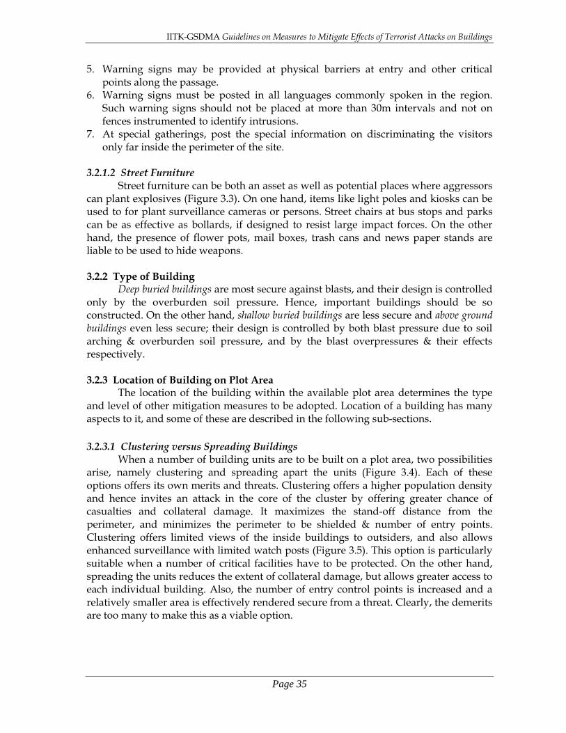
IITK-GSDMA Guidelines on Measures to Mitigate Effects of Terrorist Attacks on Buildings
Page 35
5. Warning signs may be provided at physical barriers at entry and other critical points along the passage.
6. Warning signs must be posted in all languages commonly spoken in the region. Such warning signs should not be placed at more than 30m intervals and not on fences instrumented to identify intrusions.
7. At special gatherings, post the special information on discriminating the visitors only far inside the perimeter of the site.
3.2.1.2 Street Furniture Street furniture can be both an asset as well as potential places where aggressors can plant explosives (Figure 3.3). On one hand, items like light poles and kiosks can be used to for plant surveillance cameras or persons. Street chairs at bus stops and parks can be as effective as bollards, if designed to resist large impact forces. On the other hand, the presence of flower pots, mail boxes, trash cans and news paper stands are liable to be used to hide weapons. 3.2.2 Type of Building
Deep buried buildings are most secure against blasts, and their design is controlled only by the overburden soil pressure. Hence, important buildings should be so constructed. On the other hand, shallow buried buildings are less secure and above ground buildings even less secure; their design is controlled by both blast pressure due to soil arching & overburden soil pressure, and by the blast overpressures & their effects respectively.
3.2.3 Location of Building on Plot Area
The location of the building within the available plot area determines the type and level of other mitigation measures to be adopted. Location of a building has many aspects to it, and some of these are described in the following sub-sections. 3.2.3.1 Clustering versus Spreading Buildings
When a number of building units are to be built on a plot area, two possibilities arise, namely clustering and spreading apart the units (Figure 3.4). Each of these options offers its own merits and threats. Clustering offers a higher population density and hence invites an attack in the core of the cluster by offering greater chance of casualties and collateral damage. It maximizes the stand-off distance from the perimeter, and minimizes the perimeter to be shielded & number of entry points. Clustering offers limited views of the inside buildings to outsiders, and also allows enhanced surveillance with limited watch posts (Figure 3.5). This option is particularly suitable when a number of critical facilities have to be protected. On the other hand, spreading the units reduces the extent of collateral damage, but allows greater access to each individual building. Also, the number of entry control points is increased and a relatively smaller area is effectively rendered secure from a threat. Clearly, the demerits are too many to make this as a viable option.

IITK-GSDMA Guidelines on Measures to Mitigate Effects of Terrorist Attacks on Buildings
Page 36
Figure 3.3: Elements on streets normally provided from functional requirement point of
view participate in security design (FEMA 426, 2003)

IITK-GSDMA Guidelines on Measures to Mitigate Effects of Terrorist Attacks on Buildings
Page 37
Figure 3.4: Schematic showing mitigation measures that need to be ensured at the site
level and those that need to be avoided (FEMA 426, 2003)
Figure 3.5: Advantages of Clustering: limited views of inside building and effective
surveillance with limited watch posts (FEMA 426, 2003) 3.2.3.2 Building orientation
In conventional design, orientation of a building means its orientation with respect to the path of sun, predominant natural wind direction and available natural lighting; these aspects reflect energy efficiency. However, in security-oriented design, the primary concern is the protection of building and contents against possible blast effects, while energy efficiency takes the second spot. In security design, the primary need is to increase the hardness of the structure towards the vulnerable façade. This is often achieved by the use of strong and blank defensive elements like RC structural walls, and avoiding vulnerable items like glazing on the façade of the building towards the potential explosion location (Figure 3.6). However, while the level of protection is

IITK-GSDMA Guidelines on Measures to Mitigate Effects of Terrorist Attacks on Buildings
Page 38
enhanced with this design approach, the lack of windows offers little visibility, and restricts opportunity to monitor activities outside and take appropriate protective actions from within the building in a timely manner. Therefore, these contradicting demands need to be addressed at the design stage itself, and thereby accept a known level of risk.
Figure 3.6: Placing windows with glazing along walls perpendicular to streets is a
simple but essential strategy of mitigation (FEMA 426, 2003)
3.2.3.3 Open space Providing open space (Figure 3.7) while designing the site has many benefits.
Firstly, it allows easy monitoring of people and vehicles to identify possible intruders and weapons. Secondly, blast intensity reduces drastically with increased distance, and therefore larger open space gives more protection. Thirdly, open spaces allow natural percolation of rainwater into the ground, thereby eliminating the need for drains, culverts, drainage pipes, manholes and other covert site access and weapon concealment opportunities. The space around a building can be left open but ensuring that no vehicles can drive on that land (e.g., wetland), or be densely vegetated without vehicular access providing environmental and aesthetic needs.
Figure 3.7: Clear land area around a building with un-obstructed views (FEMA 428,
2003)

IITK-GSDMA Guidelines on Measures to Mitigate Effects of Terrorist Attacks on Buildings
Page 39
3.2.3.4 Stand-off distance Recognizing that blast overpressures & their effects are much smaller at farther
distances, the distance between an asset and a explosion threat, called the stand-off distance (Figure 3.8), is used as the most effective measure for anti-terrorism. Also, this measure is cost effective as well as avoids unintended consequences that other measures may offer. There is no ideal stand- off distance; it is determined by the type of threat, the type of construction, and desired level of protection. The primary design strategy is to keep terrorists away from inhabited buildings (Figure 3.8). Although sufficient stand-off distance is not always possible in conventional construction, maximizing the distance may be the most cost-effective solution. Maximizing stand-off distance also ensures that there is opportunity in the future to upgrade buildings to meet increased threats or to accommodate higher levels of protection. Stand-off distance must be coupled with appropriate building hardening.
Figure 3.8: Concept of stand-off distance employed in explosive threats (FEMA 428,
2003) Estimating the stand-off distances for the likely explosive threats and designed accesses to the building, helps in understanding what the available exclusive zone that has assured safety from the perceived explosive threats (Figure 3.9). This presumes that there is a perimeter line, along which the last physical security verification is done on all vehicles entering the premises for entry control. The perimeter line needs to be as far away from the building as possible. In urban areas, where buildings are adjoining the sidewalk, the perimeter line can be pushed out by the use of bollards (Figure 3.10), particularly those that cannot be brought down by the collision of the intruding vehicle. Depending on the level of importance of protecting the occupants and contents of the building, additional restrictions may be applied – restricting or even eliminating parking on that lane, elimination of material loading/unloading, or even closing the lane for traffic (Figure 3.11). These measures require coordination with local municipal authorities.

IITK-GSDMA Guidelines on Measures to Mitigate Effects of Terrorist Attacks on Buildings
Page 40
Figure 3.9: Exclusive and non-exclusive zones demarcate areas of high and low levels
of protection (FEMA 428, 2003)
Figure 3.10: Use of bollards to push perimeter line outwards from a building (FEMA
426, 2003)
Figure 3.11: Closing the street to push the perimeter outward for increase protection
(FEMA 426, 2003)

IITK-GSDMA Guidelines on Measures to Mitigate Effects of Terrorist Attacks on Buildings
Page 41
As a general rule, critical services and facilities of a building should be located
well away from people access places, like main entrance, parking lots, roads on which vehicles ply and maintenance areas. Otherwise, the structure housing these facilities need to be appropriately hardened. A list of such critical facilities includes: 1. Back-up power generator 2. Fire hydrants, fire sprinkler service system and water supply units 3. Any fuel storages 4. Telephone exchange and distribution system 5. Control rooms of centrally controlled buildings 6. UPS systems supporting critical and essential services 7. Central air conditioning systems 8. Lifts, their control rooms and machinery 9. Stair cases and other cores passing utilities (e.g., power, water, gas and telephone
lines) from one floor to another 10. Main electrical power feeders line to the building and to the emergency backup
power generator 3.2.3.5 Access roads Contrary to the usual tenets of traffic planning (of minimizing time of travel and maximising speed), security-oriented design requires the designer to plan a roadway system that minimizes the vehicle speed in the proximity of the building to be protected. Thus, the roadway itself is used as a mitigation measure. This philosophy can be implemented by the following two requirements: 1. Approach roads to the building should not be straight, to prevent the vehicles from
gathering high speeds and ramming through protective barriers and crash into buildings. They must be made parallel to the façade of the building. Serpentine roads with tight-radius corners are an alternate option.
2. Approach roads must have high berms, curbs, regularly spaced appropriate trees or other measures to prevent vehicles from deviating from the roadway. For existing straight road system, the retrofit measures include barriers, bollards, swing gates, or other measures to force vehicles to travel in a serpentine path.
Other traffic calming strategies that force drivers to follow acceptable speeds in the area, are measures like raised crosswalks, speed humps, pavement treatments to create noise & riding discomfort, and introducing traffic circles. 3.2.4 Critical Utilities of Building
The critical services and facilities of a building (e.g., electric power, water, sewage, telephone lines and gas) suffer significant damage under shock wave fronts generated by explosions. In the post-attack environment, some of these are essential for safely evacuating people from the building and their failure can result in a loss disproportionately larger than that caused by the damage to the building resulting from the explosion.
The following measures help minimize the possibility of such hazards: 1. The critical services must be concealed (i.e., buried underground and/or properly
encased) to protect from effects of blasts and other sabotage possibilities. Such concealments within a building should not be made along walls of the exterior

IITK-GSDMA Guidelines on Measures to Mitigate Effects of Terrorist Attacks on Buildings
Page 42
perimeter of the building or those adjoining mail rooms. Also, unauthorized access to these must be stopped with adequate security measures.
2. There must be redundancy in the critical services particularly in those related to electricity, security, life safety and post-event emergencies. The redundant units must be adequately separated from the original unit to ensure that both are not incapacitated in the same terrorist attack. The redundant units of different utilities should not be located in the same network or run in the same chases; this will minimize the possibility of both sets of utilities being adversely affected by a single terrorist attack. When redundancy is not available, provision must be made to connect quickly portable facilities arranged for at the time of post-event emergency.
3. Vulnerability assessment shall be conducted for all critical utilities at the site, including for those that cross the site, e.g., high voltage power transmission lines.
4. Access to water storage tanks and water treatment plants, through manholes, must be security-controlled to prevent deliberate attempts of contamination. Also, regular inspection and testing must be undertaken to ensure that waterborne are not introduced.
5. While minimum signboards are used to identify critical facilities, additional measures must be undertaken to keep the unauthorized out of such premises. Fencing the utility is a basic requirement. Whenever possible, the aboveground facilities should be concealed with appropriate landscaping and plantations. Sometimes, even low impact development practices can be used to enhance security, such as retaining rain water on site in a pond to create stand-off instead of allowing it to run-off into the drainage system.
6. Flammable fuel storages shall be located at a distance of at least 30m from public access areas, like entrances, parking lots and material loading areas. Also, access to these areas must be restricted and always under lock & seal. In a hilly terrain site, such storages should be placed downhill of the operational buildings and critical facilities.
7. Communication systems based on different technologies and/or networks shall be put in place for communicating both within the site and with the outside world; the control rooms for these different technologies/networks shall be distributed throughout the campus. Such a decentralized communication system has better chances of surviving terrorist attacks. Again, all communication system equipment and cables shall be adequately concealed and protected.
8. Trash cans and garbage disposal units should be located as far away for the building as possible, with at least 10m stand-off distance.
9. Service tunnels carrying utilities must be under strict control of security personnel to prevent any aggressors from planting explosives in them or accessing the critical facilities through them.
10. Overhead equipment related to critical utilities and with 14kg or more mass, need to be formally mounted on fixtures. These fixtures need to be designed for a horizontal force of 0.5 times the equipment weight and a vertical force of 1.5 times the equipment weight. When other loadings (like seismic shaking) demand higher design forces to be considered, the same may be used.

IITK-GSDMA Guidelines on Measures to Mitigate Effects of Terrorist Attacks on Buildings
Page 43
3.2.5 Entry to site There are two types of entries along the perimeter of a site, namely (a) formal
entrances for people at the openings in the perimeter fence or boundary walls, and (b) entries for utilities like water mains, power lines, sewer pipes, communication lines, gas pipes and storm water drainages. The entrances in the former must be limited in size and only screened people are allowed entry. However, in the latter, the openings must not be too large to allow passage of persons through them. In general they must be completely sealed. But, in some instances, there may be limited access to authorized personnel only.
When access is required for maintenance at the entry of utilities on the site, special barriers shall be used, like the use of metal grating and other similar devices that prevent the access of the intruder. However, the design of the utilities should compensate for the diminished flow capacity and additional maintenance that will result from the installation of these additional grills in them. Use of sensors and remote surveillance may also be necessary when the asset to be protected is a sensitive one. The following quantitative specifications are available for the design of the entries for utilities: (a) When drainage ditches, culverts, vents and ducts passing through the site have a
cross-sectional area greater than 0.06m2 and whose smallest dimension is greater than 150mm, welded bar grills should be securely fastened at the site perimeter. Alternately, such drainage structures may be constructed of multiple pipes, each of which is not more than 250mm in diameter.
(b) When access or manholes in service tunnels or large sewer lines are 250mm diameter or larger, they should be closed with covers to prevent unauthorized opening. The covers should be locked, welded shut or bolted to their frame. The materials with which these securing devices are made shall be corrosion resistant. The manhole covers used in a very high security site should be made shatter resistant also, particularly when the miscreant attempts to make the cover brittle by artificially freezing it.
3.2.6 Surveillance 3.2.6.1 Line of Sight An important security requirement is to deny potential aggressors the line of sight from the outside the site and also from within, to the extent possible. This prevents sensitive information about operations within the site from being known explicitly to outside persons. Screening is a simple method of achieving this; this can be effectively used in conjunction with the other anti-surveillance measures of blocking sight lines, like building orientation and landscaping. When the site is at an elevated level, the advantage of being able to sight the outside activities from within is sometimes over-shadowed by the exposure of the activities within to the outside (Figure 3.12). For this reason, critical buildings should not be built on sites whose adjoining sites (a) are elevated, (b) belong to unfamiliar owners, and (c) have vegetation that offers chance for concealment of miscreants or stand-off weapons. For very critical buildings, it is sometimes ensured that there is large stand-off distance so that clear visual zones (Figure 3.7) can be maintained for visual detection of attacks. Usually, these clear zones are provided along with the other anti-surveillance measures.
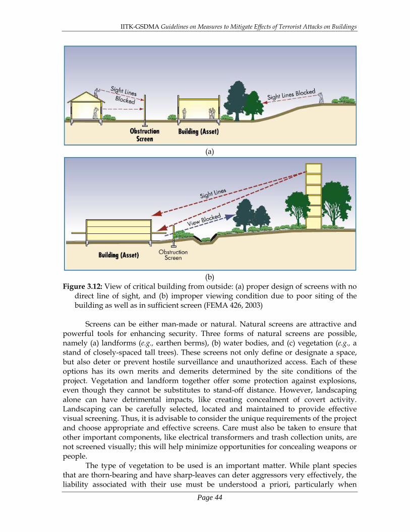
IITK-GSDMA Guidelines on Measures to Mitigate Effects of Terrorist Attacks on Buildings
Page 44
(a)
(b)
Figure 3.12: View of critical building from outside: (a) proper design of screens with no direct line of sight, and (b) improper viewing condition due to poor siting of the building as well as in sufficient screen (FEMA 426, 2003)
Screens can be either man-made or natural. Natural screens are attractive and
powerful tools for enhancing security. Three forms of natural screens are possible, namely (a) landforms (e.g., earthen berms), (b) water bodies, and (c) vegetation (e.g., a stand of closely-spaced tall trees). These screens not only define or designate a space, but also deter or prevent hostile surveillance and unauthorized access. Each of these options has its own merits and demerits determined by the site conditions of the project. Vegetation and landform together offer some protection against explosions, even though they cannot be substitutes to stand-off distance. However, landscaping alone can have detrimental impacts, like creating concealment of covert activity. Landscaping can be carefully selected, located and maintained to provide effective visual screening. Thus, it is advisable to consider the unique requirements of the project and choose appropriate and effective screens. Care must also be taken to ensure that other important components, like electrical transformers and trash collection units, are not screened visually; this will help minimize opportunities for concealing weapons or people. The type of vegetation to be used is an important matter. While plant species that are thorn-bearing and have sharp-leaves can deter aggressors very effectively, the liability associated with their use must be understood a priori, particularly when

IITK-GSDMA Guidelines on Measures to Mitigate Effects of Terrorist Attacks on Buildings
Page 45
legitimate users inadvertently come into contact with them and are injured. In contrast, the use of such vegetation may affect emergency egress from inside. Dense and tall vegetation close to the building, which covers the building, can screen unwanted activity outside. Also, grass more than 100mm thick allows concealment of explosions and other weapons. Thus, vegetation should be selected carefully, and maintained to eliminate all concealment possibilities. 3.2.6.2 Entry Control
Entry control point is required to prevent unauthorized access without hindering the smooth flow of authorized access. Entry control is usually provided only to buildings at high risk. Three types of persons need to be allowed access into a building at the perimeter of the site, namely regular staff, authorized visitors and expected service-providers. Authorized access by foot or vehicle is through designated entry points, where desired levels of control can be exercised (Figure 3.13).
Measures employed for entry control depends on the risk to the building, site conditions, and traffic type and volume. If the risk to the building is less, these can be simple rooms with no other personnel/facility but manned by guards. Existing terrain of the site influences the location of an entry control point. Generally, flat terrain is preferred with no thick vegetation. But, in some sites, a gentle rise in elevation up to the entry control point helps viewing the arriving vehicles from a distance. Natural features, e.g., water bodies and densely planted trees, enhance perimeter security and vehicle containment. In buildings where there is heavy traffic, e.g., commercial buildings, entries may be segregated for each type of the type of traffic, namely site personnel, visitors, and commercial traffic. The number of entries in each direction (arrival/departure) can vary depending on the peak-hour traffic demand of both pedestrian and vehicular traffic. Adequate lighting must be available for efficient inspection. Closed entry points must remain locked, well lit and adequately marked with warning signs. Also, buildings on the perimeter of the site should have their doors and windows locked, lighted and inspected regularly.
Figure 3.13: Options for entry control of visitors depending on the level of screening
desired (FEMA 426, 2003)
IITK-GSDMA Guidelines on Measures to Mitigate Effects of Terrorist Attacks on Buildings
Page 46
Additional items that need to be considered in the design of the entry points are: 1. At the entry point, the road must take a bend to prevent the vehicle from gaining
speed to break through the entry control station. After the entry point, (a) roads should not lead straight to the building in question, and (b) roads with heavy traffic should be kept away from the building in question. The number of roads to the building must be a minimum.
2. Keep the building away from activities on the site that draw too many people, namely commercial, service and delivery activities.
3. The design of entry control point and security guard room must allow proper verification of the vehicles and its occupants, even during peak traffic conditions. The room must be equipped with computers and communications equipment for use of security personnel; these also serve as refuge areas in an attack.
4. Adequate number of manned lanes should be provided at the entry control point to avoid backing-up of traffic in the road network approaching the entry control point. If needed, provide extra-lanes to pull over and conduct detailed inspection of some suspected vehicles. Walkway for pedestrians and a dedicated bicycle lane may be provided when considered safe.
5. Active vehicle barriers, like swing gates and speed bumps, must be provided at a designed distance before the entry control point to slow down the vehicles and provide reaction time to the security personnel to attend to the vehicle.
6. When required, inspection area must be made invisible to the public using appropriate screening. Also, the inspection area must be an enclosed station, thereby protecting the inspection equipment from adverse weather conditions. They must be large enough to accommodate at least one vehicle and have a pull-out lane. They must have equipment both the top-side and the under-side of the vehicle, and these must be based on the latest inspection technologies.
7. Special measures are required to prevent inbound vehicles from using outbound lanes; spikes along the full road width must be activated to puncture the tyres when such an attempt is made. Similar precautions should be considered to prevent a outbound vehicle from attempting to exit through the inbound lanes. To stop such “run-away” vehicles, final denial barrier should be put in place at the correct distance which can be activated as required.
3.2.6.3 Barriers
The area around a building must be separated into zones of different levels of protection (Figure 3.9), with the building having highest security protection. This is achieved with physical barriers along with access control measures at designated entry points. Physical barriers are psychological deterrents for unauthorized entry, and when entry is attempted, they delay or prevent entry, e.g., barriers provided against forced vehicular entry. The type of barrier influences both the number of entry control points and the level of security to be provided there. Barriers are of three types, namely: (a) preventive barriers, (b) protective barriers, and (c) indirect barriers. A combination of barriers often offers the best result. Consider using landscape materials to create barriers that are soft and natural rather than manmade.
Preventive barriers are continuous physical barriers placed at the perimeter of the site or around the perimeter of the exclusive areas within the site. The most common preventive barrier is fencing. The type of fencing to be used at a site depends

IITK-GSDMA Guidelines on Measures to Mitigate Effects of Terrorist Attacks on Buildings
Page 47
on the level of threat and the degree of permanence. Sometimes, they also obstruct views, provide stand-off distance to vehicle mounted explosives and weapons, and serve as a barrier to hand-thrown weapons. Some commonly used fences are chain-link fence, anti-climb fence, barbed-wire fence, barbed-tape fence and cable/rope. Anti-climb fences have different designs, including masonry walls with glass spikes on top rim, steep inclined steel vertical bars pointed outward, and horizontal tangled cables.
Protective barriers are of two types, namely passive and active barriers. The passive barriers are obstacles that are placed in the way to prevent vehicle movement; they can be permanently fixed to the ground (Figures 3.10 and 3.14) or can be re-arranged in different formations (Figure 3.14). These are to be used away from vehicle access points. The passive barriers permanently constructed in place are the most commonly used ones. The passive barriers permanently fixed to the ground (Figure 3.15) should be formally designed and detailed for an expected vehicle crash. They could be made of concrete or concrete-filled steel pipe. Bollards are an example of passive barriers (Figure 3.15a). The height of these bollards has to be at least as much as that of the fender of the vehicle, which is usually 0.6-0.9m. The spacing of the bollards contingent on a number of requirements including, the smallest width of an intruding vehicle and the number of bollards required to resist the vehicle impact. However, as a rule of thumb, the center-to-center spacing should be between 0.9-1.5m. A continuous wall of the height of the vehicle bumper is an alternative to a bollard (Figure 3.15b). For lower-risk buildings without straight-on vehicular access, surface-mounted barriers may also be used, e.g., landscaping features. Active barriers are movable systems that can be operated as and when needed (Figure 3.16). However, there are fatal consequences of the use of these active barriers and that needs to be understood.
(a) (b)
Figure 3.14: Passive barriers that can be (a) fixed to ground, and (b) moved to different locations requiring protection (FEMA 426, 2003)

IITK-GSDMA Guidelines on Measures to Mitigate Effects of Terrorist Attacks on Buildings
Page 48
(a) (b) Figure 3.15: Reinforced concrete passive barriers that are permanently fixed to ground
(a) bollards, and (b) continuous wall (FEMA 426, 2003)
Figure 3.16: Active barrier to prevent movement of vehicles (FEMA 426, 2003)
Indirect barriers are features that have some other primary intention, but also offer the same advantages of a physical barrier. For example, the blocking of streets to prevent vehicular access into a certain area pushes outward the perimeter of the protected zone (Figure 3.11). Walkways away from the building also mean a certain amount of increased protection. Sometimes, the main facility to be protected in a building is way inside its exterior walls. In such cases, the perimeter building walls themselves (made of masonry or cast-insitu concrete) act as a perimeter barrier. Openings in such perimeter walls should be protected from the inside with appropriate fastenings.
Partial use of barriers is also employed when the vehicular access is clearly limited to one side of the building and the other side is adequately secure (Figure 3.17). Additional entry control points and patrols are to be used along with these partial barriers. Vehicles placed in front of buildings or across access roads, can be used as

IITK-GSDMA Guidelines on Measures to Mitigate Effects of Terrorist Attacks on Buildings
Page 49
temporary physical barriers. High curbs, low berms and shallow ditches are also effective strategies to protect from stationary bombs at a distance.
Figure 3.17: Partial barricading with passive barriers to cover threats in a limited way
(FEMA 426, 2003) 3.2.7 Parking
Vehicles transport weapons and aggressors to a building. Therefore, restricting vehicular parking can help in keeping potential threats away. In urban areas, roadside and underground parking is necessary, but can be difficult to restrict. Therefore, creative measures are required to mitigate the risks associated with parking. The measures can be both structural as well as operational measures. The former may include parking restrictions, perimeter buffer zones, barriers, structural hardening, and other architectural and engineering solutions. And, the latter may include inspecting and screening vehicles entering parking garages. Parking should not be provided underneath (i.e., in the basement of) the most critical (high risk) buildings (or underneath certain critical parts of these buildings) since this is one of the easy routes for terrorists in spite of security measures. The 1993 WTC bombing experience reiterated that consequences of bombing can be disastrous when parking is provided underneath the building.
The following measures are required to reduce parking related risks: 1. Parking lots should be located away from high-risk buildings to minimize blast
effects of potential vehicle bombs. 2. Parking for both visitors and general public should be kept together. The number of
locations for vehicular entry/exits must be kept to a minimum. Likewise, pedestrian paths also should be a minimum, thereby keeping all pedestrians within a limited area and improving ability to see and to be seen by others.

IITK-GSDMA Guidelines on Measures to Mitigate Effects of Terrorist Attacks on Buildings
Page 50
3. In large building premises, parking should be restricted from the inside courtyards. 4. Parking within the secured perimeter must be restricted to authorized personnel. 5. General parking must be located (a) away from stand-off zone, (b) within the view
of occupied buildings, and (c) such that the risk to people is the least. 6. One-way flow of traffic is preferable to facilitate better monitoring of potential
aggressors. 7. Parking areas must be provided with emergency telephone or intercom systems,
and located at readily identified, well-lighted, closed circuit television monitored locations to permit direct contact with security personnel.
8. Curb-side parking in densely populated areas must be restricted to company-owned vehicles or select employee vehicles.
9. Parking lots must have sufficient setback from adjacent properties; the location of the building on the site should be adjusted to provide adequate setback from adjacent properties. In the absence of that, structural hardening measures should be undertaken.
10. Parking under the building and, where applicable, within its internal courtyard, must be prohibited to the extent possible. When parking under the building becomes essential, (a) access must be limited to authorized persons only; (b) such areas must be secure, well-lighted, and free of places of concealment; (c) avoid non-parking dead zones; (d) the primary vertical load carrying members must have at least 150mm stand-off
distance; and (e) the columns in the garage area must be designed for an unbraced length equal to
the height of two floors when the parking is in a single basement, and of three floors parking is on two basement floors.
11. In standalone parking garages that are built above ground, (a) visibility into and out of the parking garages must be maximized; (b) ramps must be employed to quickly vacate the vehicles to flat parking surfaces; (c) landscaping should not create hiding places; and (d) staircases and elevator lobbies must be as open and well-lit as possible so that people using the elevators can be seen; the use of glass walls for the elevator units is encouraged to deter potential attacks; and (e) potential hiding places below stairs should be closed.
12. Trees and plantations should be grown away from parking garages and parking lots to allow observation of pedestrians.

IITK-GSDMA Guidelines on Measures to Mitigate Effects of Terrorist Attacks on Buildings
Page 51
3.3 Architectural Considerations Security-oriented design of buildings involves a number of decisions to be made even before embarking into quantitative design computations. These decisions are intuitive and qualitative, but have significant impact on the level of protection finally achieved. In particular, the architectural aspects of design of a building lend themselves to a number of such decisions. Often, the cost involved in implementing these architectural aspects is small, if implemented in the early stages of design. For this reason, consultants with specialization in security-oriented design must participate from site planning through to building finishing.
Three aspects come under the purview of architectural considerations, namely architectural configuration, functional planning and non-structural elements. If not accounted for, each of these aspects can result in a major deficiency of the structure.
3.3.1 Architectural Configuration Under blast loading, the shock wave front is modified by the geometry of the land. Thus, the shock wave front interacts with both form of the building and landscape around it. The shape and size of the building can be so chosen that effects due to exterior explosions around a building are mitigated. 3.3.1.1 Shape
The shape of the building has a significant influence on the overall damage sustained by a building under blast loading caused by explosions. In the path of the shock wave front, a building with an aerodynamic shape will perform better than those without. So, the main effort in identifying favourable shape of the building is to identify all its geometric features that prevent smooth aerodynamic flow of shock front around it, trap the shock wave and amplify the effects of air blast (Figure 3.18). Buildings with simple geometries with minimal ornamentation are ideally suited from security-based design considerations.
There are two basic exterior shapes of buildings, namely convex and concave (Figure 3.19); the former are better. The latter shapes have a number of inside dead ends, called re-entrant corners, which trap the shock wave overpressure; examples are U- or L-shaped buildings. Hence, convex shapes are preferred over concave shapes. Circular plan buildings and buildings with circular corner surfaces have less intense reflected pressure than a rectangular building with sharp corners, because the angle of incidence of the shock wave increases more rapidly than in a rectangular building. (Figure 3.20). Also, large or gradual re-entrant corners and overhangs are preferred over small and sharp ones. To this extent, the considerations of identifying the overall building shape are same for both the earthquake-resistant or wind/cyclone-resistant design and the security-based design. When buildings are decorated with ornamentation, lightweight materials (e.g., timber and plastic) are preferable as these are less likely to act as lethal projectiles in the event of explosions, in comparison to other commonly used building materials (e.g., brick, stone, or metal). In particular, roofing material has a greater tendency to be sucked up under blast loading.
While planning commercial and office buildings, often plaza-type construction are chosen, wherein the set-back on the front is large and on the other three sides little or none. This configuration may make an architectural statement, but makes the building vulnerable on the other three sides because of lesser stand-off distance.

IITK-GSDMA Guidelines on Measures to Mitigate Effects of Terrorist Attacks on Buildings
Page 52
(a) (b) Figure 3.18: Influence of building shape on blast effects on buildings: (a) shapes that
dissipate air blast, and (b) shapes that accentuate sir blast (FEMA 427, 2003) Figure 3.19: Two basic geometries of architectural forms, in plan and in elevation; the
convex is superior
Figure 3.20: Threat to buildings with re-entrant corners facing the street or possible direction from which the explosion is expected.
Convex Concave
IITK-GSDMA Guidelines on Measures to Mitigate Effects of Terrorist Attacks on Buildings
Page 53
Walls with soil cover on the side perform well under blast loading; soil is highly effective in reducing the impact of explosions. Buildings with buried roofs are extremely successful in military applications; they can be used also in civilian constructions with security-based design.
Thus, the following design considerations are recommended: 1. Wherever possible, use earth-sheltered buildings and reduce their vulnerability to
explosive attacks and the consequent blast effects. 2. Buildings oriented horizontally have a smaller exposure to blast effects than those
oriented vertically. 3. Plinth level of the building should be placed at least 1.2m above ground to prevent
vehicles from ramming in. 4. Overhangs and eaves attract high overpressures during blasts, and hence such
features must be avoided. But, when they cannot be avoided, they must be designed to resist the appropriate blast effects.
5. Building must be oriented such that walls with glazing must be oriented perpendicular to the street-side façade to reduce exposure to blast.
6. Vertical load carrying elements of the building, like columns and structural walls, should not be exposed on the exterior façade.
7. Use pitched roofs to deflect explosives hurled at the buildings, as well as to reduce the effects of blast overpressures.
8. When blast overpressures are expected, re-entrant corners must be avoided in the exterior of the building.
3.3.1.2 Size
Vertically-spread and horizontally-spread buildings, both offer challenges. While the latter seems better, just as in the cases of clustered versus dispersed buildings discussed in previous section of this chapter, even here designers need to consider a number of relevant factors like economy, before deciding on any of these options.
On the one side, low large-footprint buildings distribute people, assets and operations over a larger plan area; this limits damage. Tree cover, terrain and other screening elements are effective to protect such buildings. These buildings can be made energy efficient by employing green roof technologies, but additional mitigation measures are required to protect injection of CBR agents into the HVAC.
On the other hand, tall small-footprint buildings suffer more extensive damage to their façades, structural elements and interiors; catastrophic damage or progressive collapse cannot be ruled out, if a large blast occurs near the building, which is not accounted for in design. It is difficult to protect them form outside surveillance. However, these buildings have smaller plan area resulting in reduced storm water runoff; this reduces the need for culverts, drainage pipes, manholes and other features that offer opportunities to penetrate the site or conceal weapons. Also, in these buildings, the HVAC units can be moved to upper locations and thereby prevent introduction of the CBR agents into them. 3.3.2 Functional Planning
Functionally planning the usable spaces of the building adds to mitigation of losses due to terrorist attack. Before embarking on conducting functional planning, all spaces of the building must be understood, especially in terms of the areas that need

IITK-GSDMA Guidelines on Measures to Mitigate Effects of Terrorist Attacks on Buildings
Page 54
security and those that add to vulnerability. Areas that need to be secured should not be seen from a street. Whenever possible, they should face courtyards or areas other than those that add to vulnerability. Alternately, suitable glazing should be provided to prevent clear vision; this glazing should be ballistic-resistant as well as blast resistant. Places that allow hiding inside the building must be eliminated.
Areas to be secured (e.g., class rooms, toilets, child care facilities and control rooms of special surveillance facilities) need to be separated adequately from those that add to vulnerability (e.g., lobbies, material delivery areas, post office rooms, garages, and retail sales are areas where bulk quantities of CBR agents are likely to be introduced in a building), both within floors in plan and across floors in elevation. Areas that add vulnerability should be placed outside the footprint of the main building; if that is not possible, at least they must be placed along the exterior of the building. In no case, such areas should be located directly under the footprint of the main building (Figure 3.21). Such a strategy reduces the impact of explosions on the main building, avoids blast under the building which can lead to progressive collapse, and reduces movement of potential aggressors inside the main building.
(a) (b) Figure 3.21: Strategies for locating functional spaces in creating secure and unsecured
areas in buildings: (a) original layout and (b) improved layout (adapted from FEMA 427, 2003)
The structural members should not be left exposed adjoining the areas that add
vulnerability to the building. Therefore, more hardened areas (like stair cases, elevator cores and dead storage areas) than the regular building frame should be placed in between the areas that add vulnerability and those that need to be secured. However, emergency services (e.g., water sprinklers and power generators, which are required for mitigating effects of an explosion) and elevators meant for emergency services should be placed away from the areas that add vulnerability. This was clearly demonstrated in the 1993 World Trade Center bombing incident, when elevator shafts served as chimneys transmitting smoke and heat from the explosion in the basement to the upper levels of the building; this led to smoke inhalation injuries and also severely affected evacuation process. When it is not possible to separate areas that add vulnerability and those that need to be secured, use reinforced concrete walls in between these two areas as the vertical elements of the structural system and design them to resist forces generated by the explosion.
The doors of hallways that connect the outside of the building to the inside should be staggered across the hallway to mitigate the effects of blast loading (Figure 3.22). Such hallways must have reinforced concrete structural walls around them.

IITK-GSDMA Guidelines on Measures to Mitigate Effects of Terrorist Attacks on Buildings
Page 55
Design of functional spaces must consider venting the blast overpressure forces and gases from the interior spaces to the outside of the structure. For this, one can use blow-out panels protect from overpressures applied from outsides, but blow out when subjected to internal overpressures.
Figure 3.22: Staggered doorways to prevent venting effect of blast overpressures
through hallways of buildings. (FEMA 426, 2003) The Command Center of a building is the location from where the control
operations are undertaken in the event of an emergency in that building. Often, such command centers are located within the building and usually in the 1st storey level. It has been learnt from the past disasters that the alternate location away from the main building is a much better option since the survival of and access to the command center is critical in the emergency.
3.3.3 Non-structural Elements
Explosions may cause some non-structural elements (e.g., false ceilings, light fixtures, venetian blinds, ductwork and air conditioners) to become flying debris. Thus, such options should be avoided wherever possible. Heavy equipment (e.g., air conditioners) should be placed near the floor than at elevations. Lighter equipment (e.g, computer terminals) should be placed farthest from the exterior walls to prevent injuries due to blast overpressure effects; for the same reason, even conference rooms should be placed away from the exterior perimeter of the building. Light attachments (e.g., light fixtures) should be fixed formally to the slab above using mechanical assemblies. Cloth curtains should be preferred over metal and plastic venetian blinds. A major concern in security-oriented design is contamination of the air (through either of chemical, biological, radiological or other hazardous materials) in the natural or mechanical ventilation system. Hence, the use of natural ventilation in security-design buildings may have to be strictly reviewed in light of the possible threats. 3.3.3.1 Utilities Utilities are essential services that are required to be functional even after a terrorist attack on the building. Equipment related to the utilities can be damaged

IITK-GSDMA Guidelines on Measures to Mitigate Effects of Terrorist Attacks on Buildings
Page 56
themselves by explosive attacks; thus, critical controls, wiring and piping related to these equipment must be adequately protected. But, the main threat to these facilities is through CBR attack. In particular, facilities like centralized air handling facilities are prime candidates for injecting CBR agents to cause harm to the occupants of the building. Thus, these services must continue to operate and provide life safety-related services. This is accomplished by locating these systems at less vulnerable areas of the building as well as providing redundancy by putting in place backup units that can be put into force in the event of an attack. Also, utility lines (like plumbing and electrical lines) in the building should not be mounted on the inside of exterior walls. Whenever possible, an additional wall must be built at least 150mm from the exterior façade wall and used to mount these facilities. Also, these services should neither be placed on rooftops nor hung from roof/floor slabs. Further, the number of access manholes to the utility lines must be minimized. Even these few man-hole accesses must remain locked, except when needed to be inspected by authorized personnel. HVAC systems control heat, ventilation and air conditioning in buildings. For this, air handling units (AHU) take in air from outside the building, modify the same to suit the inside conditions and supply that through the building ventilation systems. Hence, a potential threat to this is the air intake facility, namely the AHU. These facilities need to be kept away from potential sabotage, i.e., by placing these at a high elevation (Figure 3.23a). The air adjacent to the outside façade of the building does not usually rise up unless there is a strong outside wind, and even if the CBR agent injected rises up in air, its concentration decreases with height because of dispersion. Further, some CBR agents are heavier than air and may not rise above the ground level. Thus, elevated air intake units avoid possibilities of injecting CBR agents by passers by. Also, these units must be built flush inside the building wall and provided with screens so that no one can hurl any injection into the system. Also, these AHUs should not project out of the building façade, thereby adding to their protection under blast loading (Figure 3.23b).
To prevent injection of CBR agents by hurling into the mouths of the air intake units, metal gratings covers should be provided that are sloped (Figure 3.24). This forces these objects with CBR injection to roll off the covers, away from the intake units. When existing buildings have air intakes located at or below ground level. These could be either wall-mounted or below-grade but close to the building. These intake units should be covered with an external shaft-like cover that is elevated at least 3.6m from the ground level (Figure 3.25). This will keep the aggressors from climbing on to the intake unit without help or equipment. In view of the above, it is preferred that air intake units are kept on roof of buildings and access to such rooftops is restricted to authorized personnel.
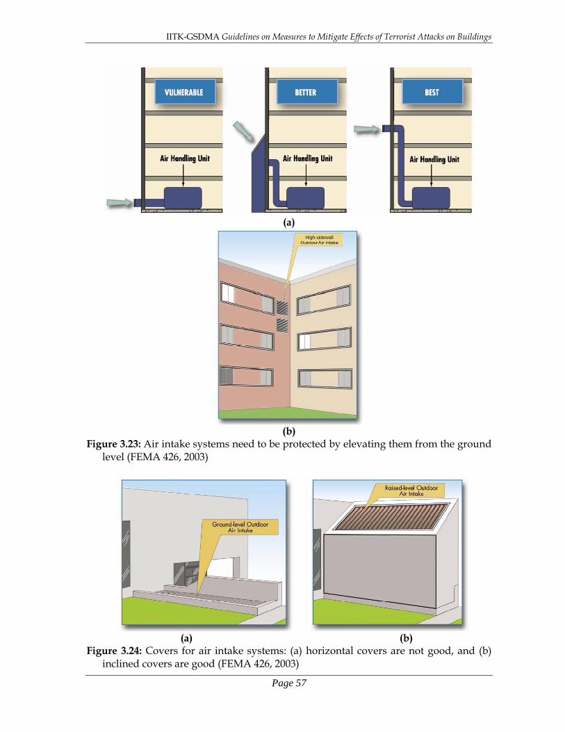
IITK-GSDMA Guidelines on Measures to Mitigate Effects of Terrorist Attacks on Buildings
Page 57
(a)
(b)
Figure 3.23: Air intake systems need to be protected by elevating them from the ground level (FEMA 426, 2003)
(a) (b) Figure 3.24: Covers for air intake systems: (a) horizontal covers are not good, and (b)
inclined covers are good (FEMA 426, 2003)
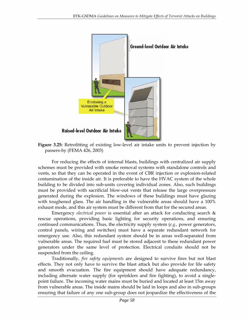
IITK-GSDMA Guidelines on Measures to Mitigate Effects of Terrorist Attacks on Buildings
Page 58
Figure 3.25: Retrofitting of existing low-level air intake units to prevent injection by
passers-by (FEMA 426, 2003)
For reducing the effects of internal blasts, buildings with centralized air supply schemes must be provided with smoke removal systems with standalone controls and vents, so that they can be operated in the event of CBR injection or explosion-related contamination of the inside air. It is preferable to have the HVAC system of the whole building to be divided into sub-units covering individual zones. Also, such buildings must be provided with sacrificial blow-out vents that release the large overpressure generated during the explosion. The windows of these buildings must have glazing with toughened glass. The air handling in the vulnerable areas should have a 100% exhaust mode, and this air system must be different from that for the secured areas.
Emergency electrical power is essential after an attack for conducting search & rescue operations, providing basic lighting for security operations, and ensuring continued communications. Thus, the electricity supply system (e.g., power generators, control panels, wiring and switches) must have a separate redundant network for emergency use. Also, this redundant system should be in areas well-separated from vulnerable areas. The required fuel must be stored adjacent to these redundant power generators under the same level of protection. Electrical conduits should not be suspended from the ceiling. Traditionally, fire safety equipments are designed to survive fires but not blast effects. They not only have to survive the blast attack but also provide for life safety and smooth evacuation. The fire equipment should have adequate redundancy, including alternate water supply (for sprinklers and fire fighting), to avoid a single-point failure. The incoming water mains must be buried and located at least 15m away from vulnerable areas. The inside mains should be laid in loops and also in sub-groups ensuring that failure of any one sub-group does not jeopardize the effectiveness of the
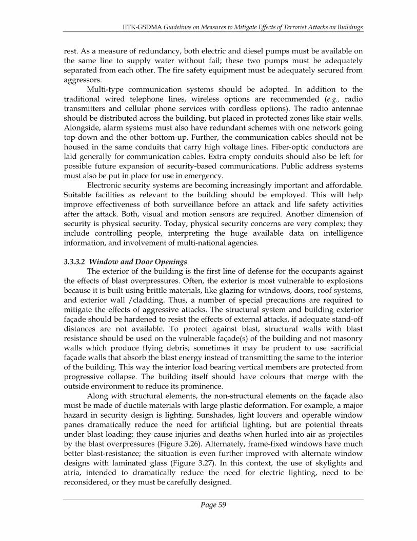
IITK-GSDMA Guidelines on Measures to Mitigate Effects of Terrorist Attacks on Buildings
Page 59
rest. As a measure of redundancy, both electric and diesel pumps must be available on the same line to supply water without fail; these two pumps must be adequately separated from each other. The fire safety equipment must be adequately secured from aggressors. Multi-type communication systems should be adopted. In addition to the traditional wired telephone lines, wireless options are recommended (e.g., radio transmitters and cellular phone services with cordless options). The radio antennae should be distributed across the building, but placed in protected zones like stair wells. Alongside, alarm systems must also have redundant schemes with one network going top-down and the other bottom-up. Further, the communication cables should not be housed in the same conduits that carry high voltage lines. Fiber-optic conductors are laid generally for communication cables. Extra empty conduits should also be left for possible future expansion of security-based communications. Public address systems must also be put in place for use in emergency.
Electronic security systems are becoming increasingly important and affordable. Suitable facilities as relevant to the building should be employed. This will help improve effectiveness of both surveillance before an attack and life safety activities after the attack. Both, visual and motion sensors are required. Another dimension of security is physical security. Today, physical security concerns are very complex; they include controlling people, interpreting the huge available data on intelligence information, and involvement of multi-national agencies. 3.3.3.2 Window and Door Openings
The exterior of the building is the first line of defense for the occupants against the effects of blast overpressures. Often, the exterior is most vulnerable to explosions because it is built using brittle materials, like glazing for windows, doors, roof systems, and exterior wall /cladding. Thus, a number of special precautions are required to mitigate the effects of aggressive attacks. The structural system and building exterior façade should be hardened to resist the effects of external attacks, if adequate stand-off distances are not available. To protect against blast, structural walls with blast resistance should be used on the vulnerable façade(s) of the building and not masonry walls which produce flying debris; sometimes it may be prudent to use sacrificial façade walls that absorb the blast energy instead of transmitting the same to the interior of the building. This way the interior load bearing vertical members are protected from progressive collapse. The building itself should have colours that merge with the outside environment to reduce its prominence. Along with structural elements, the non-structural elements on the façade also must be made of ductile materials with large plastic deformation. For example, a major hazard in security design is lighting. Sunshades, light louvers and operable window panes dramatically reduce the need for artificial lighting, but are potential threats under blast loading; they cause injuries and deaths when hurled into air as projectiles by the blast overpressures (Figure 3.26). Alternately, frame-fixed windows have much better blast-resistance; the situation is even further improved with alternate window designs with laminated glass (Figure 3.27). In this context, the use of skylights and atria, intended to dramatically reduce the need for electric lighting, need to be reconsidered, or they must be carefully designed.

IITK-GSDMA Guidelines on Measures to Mitigate Effects of Terrorist Attacks on Buildings
Page 60
Figure 3.26: Snap shots of shattering of an unprotected window glass in a large
explosion (FEMA 426, 2003)
Figure 3.27: Failure modes of safe laminated-glass window systems for blast resistance
(FEMA 427, 2003)
Windows on the exterior façade of a building should be designed to reduce flying glass debris under blast. Further, the design of the window system (consisting of connection of frame to wall, frame, connection of frame to glass, and glass) should be balanced. This means all the components and connections should have capacities such that they fail together at the same blast overpressure; here, both damage sequence and extent of damage are controlled. In the event of an exterior blast, Figure 3.28 shows how far the glass fragments would enter a room and injure occupants. Thus, the interior of the building must be designed accordingly. Also, use of heat-resistant glass minimized the extent of damage in case of fire, since preventing breaking of glass is critical for controlling the fire growth and stopping fire spread.

IITK-GSDMA Guidelines on Measures to Mitigate Effects of Terrorist Attacks on Buildings
Page 61
Figure 3.28: Elevation of a room showing performance conditions depending on relative location from window (FEMA 427, 2003)
0.6m (2 feet) above the floor.
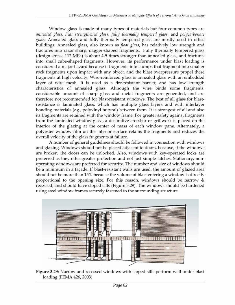
IITK-GSDMA Guidelines on Measures to Mitigate Effects of Terrorist Attacks on Buildings
Page 62
Window glass is made of many types of materials but four common types are annealed glass, heat strengthened glass, fully thermally tempered glass, and polycarbonate glass. Annealed glass and fully thermally tempered glass are mostly used in office buildings. Annealed glass, also known as float glass, has relatively low strength and fractures into razor sharp, dagger-shaped fragments. Fully thermally tempered glass (design stress: 112 MPa) is about 4-5 times stronger than annealed glass, and fractures into small cube-shaped fragments. However, its performance under blast loading is considered a major hazard because it fragments into clumps that fragment into smaller rock fragments upon impact with any object, and the blast overpressure propel these fragments at high velocity. Wire-reinforced glass is annealed glass with an embedded layer of wire mesh. It is used as a fire-resistant barrier, and has low strength characteristics of annealed glass. Although the wire binds some fragments, considerable amount of sharp glass and metal fragments are generated, and are therefore not recommended for blast-resistant windows. The best of all glass for blast-resistance is laminated glass, which has multiple glass layers and with interlayer bonding materials (e.g., polyvinyl butyral) between them. It is strongest of all and also its fragments are retained with the window frame. For greater safety against fragments from the laminated window glass, a decorative crossbar or grillwork is placed on the interior of the glazing at the center of mass of each window pane. Alternately, a polyester window film on the interior surface retains the fragments and reduces the overall velocity of the glass fragments at failure.
A number of general guidelines should be followed in connection with windows and glazing. Windows should not be placed adjacent to doors, because, if the windows are broken, the doors can be unlocked. Also, windows with key-operated locks are preferred as they offer greater protection and not just simple latches. Stationary, non-operating windows are preferred for security. The number and size of windows should be a minimum in a façade. If blast-resistant walls are used, the amount of glazed area should not be more than 15% because the volume of blast entering a window is directly proportional to the opening size. For this reason, windows should be narrow & recessed, and should have sloped sills (Figure 3.29). The windows should be hardened using steel window frames securely fastened to the surrounding structure.
Figure 3.29: Narrow and recessed windows with sloped sills perform well under blast
loading (FEMA 426, 2003)

IITK-GSDMA Guidelines on Measures to Mitigate Effects of Terrorist Attacks on Buildings
Page 63
Even doors must be designed to be balanced, i.e., the components of the door system (door panel, frame and fasteners) should fail simultaneously. In particular, exterior doors panels should be designed to resist the blast overpressures and preferably made of steel. The number of exterior doors should be a minimum and should open outward from the building. They must be provided with locking system from the inside to prevent tampering. When glass doors are used, they must be backed up with solid doors or walls immediately behind them. 3.3.3.3 Roof Systems
External blasts cause downward overpressures on roofs. However, if this blast overpressure enters the building through the doors and windows openings, upward pressure is also caused. Both these should be considered simultaneously, if they occur that way, else they can be considered to act separately. The roof that is most effective is the cast in-situ RC roofs with beams in both directions and with the roof tied down to the vertical load carrying system, wherein beams have stirrups with 135º hooks along the full length, and at spacing not greater than half the beam depth. Alternately, steel frames with a concrete-metal deck composite slab can also be used. All-metal roofs, precast roofs, flat slab roofs and prestressed roofs are not effective. Some designers prefer to have a sacrificial sloping roof on buildings with a formally designed protected ceiling (Figure 3.30). Access to roofs should be controlled to minimize sabotage in the form of planting explosives or CBR agents. Accesses to roofs must only be from internal staircases.
Figure 3.30: Use of a sacrificial roof in important buildings is an effective strategy in
blast-resistant design (FEMA 426, 2003)

IITK-GSDMA Guidelines on Measures to Mitigate Effects of Terrorist Attacks on Buildings
Page 64
3.3.3.4 Exterior Wall /Cladding The exterior walls provided are subject to direct blast overpressures. They should be designed to fail in a ductile manner, i.e., in flexural tension than in shear, including the loads transferred from the blast loading on windows and doors. Therefore, special reinforcements should be provided around window and door frames. Sometimes, bullet-resistant windows have ultimate capacity larger than the walls to which they are attached. When the highest protection is required, cast-in-situ RC walls should be used. But, precast concrete and metal-claddings may be used to achieve lower levels of protection. Security design strategies do not allow the use of brick veneers and other nonstructural elements attached to the exterior façade of the building. 3.3.3.5 Stair Cases Stair cases play critical role in case of an attack and emergency, and hence, their location and arrangement is critical for evacuation of occupants and for access to security personnel. Locations surrounding stair case (and elevators) should be constructed with heavy weight construction to mitigate damage and also they should be arranged in corners (not staggered in one place). Further, painting the stairs with photo-luminescent paint (which costs very little) helps in easy evacuation in emergencies. Lessons from the collapse of the WTC provide strong support for this [FEMA 403, 2002]. 3.4 Structural Aspects In security-based design, buildings and structures stand as shields between their occupants & contents and the aggressive attacks. Two types of attacks are of prime concern, namely blast loading and missile impact. Protecting the asset from both disintegrating and collapsing is the central theme of this design. Just as in seismic design, even here, the choice of the structural system plays a critical role in determining the success of security design. However, significant attention is paid to performance of individual elements as localized damage is seen to be a prime reason for progressive collapse in buildings and structures. Broadly, the requirements of the structure under blast loading and missile impact related to lateral resistance and detailing of individual elements are in line with those for strong seismic shaking. Buried structures perform better than above grade structures. However, the conventional constructions will be above grade structures. Designing these structures to have no damage is generally impractical because of the following reasons (Longinow and Mniszewski, 1996): (a) The level of risk cannot be ascertained with any accuracy. There are uncertainties in
which building will be attacked, at which location near a building and at what time. (b) The threat cannot be clearly quantified. The weapon type, its size or its mode of
delivery are not known. (c) Blast pressures cause loading effects that are orders of magnitude larger than the
gravity or wind loads. The cost of designing for such effects is huge and often not acceptable.
However, significant improvement can be achieved in reducing the vulnerability of building by adopting some basic norms of blast resistant constructions.
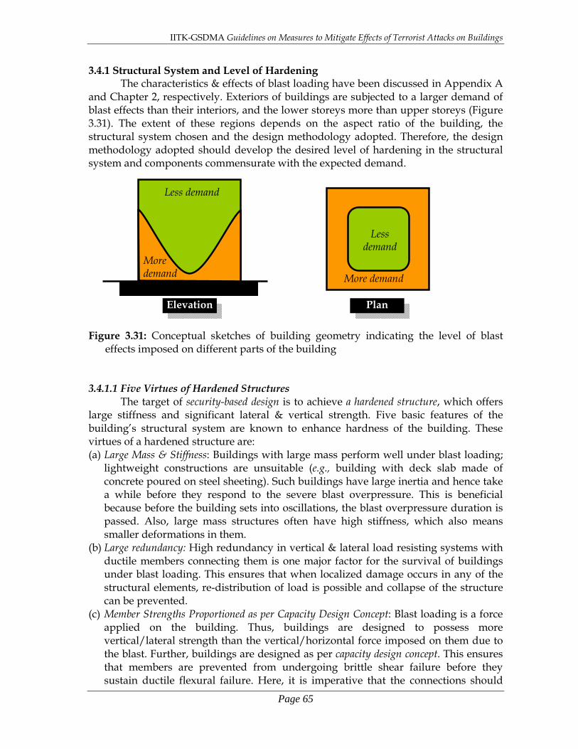
IITK-GSDMA Guidelines on Measures to Mitigate Effects of Terrorist Attacks on Buildings
Page 65
3.4.1 Structural System and Level of Hardening The characteristics & effects of blast loading have been discussed in Appendix A
and Chapter 2, respectively. Exteriors of buildings are subjected to a larger demand of blast effects than their interiors, and the lower storeys more than upper storeys (Figure 3.31). The extent of these regions depends on the aspect ratio of the building, the structural system chosen and the design methodology adopted. Therefore, the design methodology adopted should develop the desired level of hardening in the structural system and components commensurate with the expected demand. Figure 3.31: Conceptual sketches of building geometry indicating the level of blast
effects imposed on different parts of the building 3.4.1.1 Five Virtues of Hardened Structures
The target of security-based design is to achieve a hardened structure, which offers large stiffness and significant lateral & vertical strength. Five basic features of the building’s structural system are known to enhance hardness of the building. These virtues of a hardened structure are: (a) Large Mass & Stiffness: Buildings with large mass perform well under blast loading;
lightweight constructions are unsuitable (e.g., building with deck slab made of concrete poured on steel sheeting). Such buildings have large inertia and hence take a while before they respond to the severe blast overpressure. This is beneficial because before the building sets into oscillations, the blast overpressure duration is passed. Also, large mass structures often have high stiffness, which also means smaller deformations in them.
(b) Large redundancy: High redundancy in vertical & lateral load resisting systems with ductile members connecting them is one major factor for the survival of buildings under blast loading. This ensures that when localized damage occurs in any of the structural elements, re-distribution of load is possible and collapse of the structure can be prevented.
(c) Member Strengths Proportioned as per Capacity Design Concept: Blast loading is a force applied on the building. Thus, buildings are designed to possess more vertical/lateral strength than the vertical/horizontal force imposed on them due to the blast. Further, buildings are designed as per capacity design concept. This ensures that members are prevented from undergoing brittle shear failure before they sustain ductile flexural failure. Here, it is imperative that the connections should
Elevation
Less demand
More demand
Less demand
More demand
Plan

IITK-GSDMA Guidelines on Measures to Mitigate Effects of Terrorist Attacks on Buildings
Page 66
allow this without themselves being damaged. Such an approach enhances the energy absorption capacity of the structure.
(d) Resistance to Reversed Loading: The structural design of the primary structural members (resisting vertical and lateral loads) accounts for reversal of blast overpressures loads, namely the positive pressure phase followed by negative pressure phase. Thus, structural systems with gravity load-based prestressing and with seated connections should not be used. In particular, roofing systems should be bolted or anchored down to prevent lift-off under upward pressure in buildings.
(e) Strong Connections: Connections between the structural elements must be strong to allow large deformations without dropping strength, and thereby facilitate redistribution of loads from one vertical & lateral load resisting system to another in a ductile manner. Over the years, cast-in-situ RC constructions have performed well in many military applications, e.g., military bunkers. Extensive research and testing of cast-insitu RC structures confirms that it is possible to (a) detail RC beams to perform in a ductile manner, and (b) design columns with large cross-sectional area so that they do no buckle when large overpressures cause a sudden increase of axial loads in them.
3.4.1.2 Choice of Structural System
Choosing a structural system to resist blast loading is an important task. Four structural systems are commonly used in buildings, namely load-bearing structures, moment frame structures, braced frame structures and moment frame-wall structures. Of these, the load-bearing buildings are the most vulnerable as they readily disintegrate into its masonry constituents. Thus, load-bearing walls should be kept away from the exterior vulnerable façade of the building, if not avoided. When compelled to use as the main walls in the interior, load bearing walls should be closely spaced to enhance stability and to prevent lateral progression of damage. And, if used as the main on the exterior, a second line of load bearing walls should be provided close to the perimeter which will come into force when the exterior façade is damaged.
On the other hand, the performance of the other building systems (namely moment frame, braced frame and moment frame-wall systems) under blast loading is critically contingent on the level of detail incorporated in the design. Thus, qualified engineers alone should be employed in designing such structures.
3.4.2 Progressive Collapse Analysis
Two design requirements determined by the type of weapon are (1) direct effects of blast causing extensive damage to the façade and (2) localized damage due to attack on individual elements leading to progressive collapse. In progressive collapse, the failure of a member in the primary load resisting system leads to redistribution of force to the adjoining members. If the adjoining member cannot resist the additional load, then even that member fails. This process continues in the structure and eventually the building collapses. Thus, the failure of a member at the local level results in the collapse of the structure at the global level, in a progressive manner, one member at a time. Of these two design requirements, the design for the latter is the most difficult.
Thus, the main concern of ensuring lateral resistance in buildings is preventing progressive collapse. Irrespective of the building function, structural system used in it, and the level of security employed in it, every building should be designed to prevent

IITK-GSDMA Guidelines on Measures to Mitigate Effects of Terrorist Attacks on Buildings
Page 67
progressive collapse. Redundancy is the first measure to ensure that there are many alternate load paths and increased number of locations where plastic hinges must occur before the structure collapses. Members where plastic hinges are likely to form should have ductile detailing incorporated in them to perform in a ductile manner, and the other non-ductile members must be designed as per capacity design concept, thus minimizing the possibility of progressive collapse.
The methodology to be employed is described below in brief for ensuring that progressive collapse does not occur: (a) Perform structural analysis of the building by removing one important element in
the load path, e.g., column, load-bearing wall or beam, to simulate local damage from an explosion. The method of analysis can be both linear and nonlinear, and within that both static as well as dynamic.
(b) Check if the available load path in the remaining structure is able to resist the loading. If it can, the exercise is repeated by removing another critical element in the load path. Otherwise, the structure is rendered vulnerable.
(c) If in all possible cases of removal of an important member in the load path, one at a time, the structure is able to resist the loading, the structure is said to meet the progressive collapse requirement.
While the above basic guidelines to identify critical structural elements to be removed from the structural design configuration helps in understanding the implications of its failure, a clear procedure or strategy is not available to arrive at a structural model to be used to guarantee the effectiveness of available load paths. Also, most design codes of practice of the world require some form of analysis or measures to reduce the potential for progressive collapse, but no specific engineering design method is prescribed for the structural design process to prevent progressive collapse. It is left to the owner and the associated design team to determine the appropriate strategies. 3.4.2.1 Design Methods
Three methods are identified in literature (ASCE 7, 2002) for structural design of buildings to mitigate damage due to progressive collapse when blast loading initiate collapse. These are: (a) Indirect Method: Prescriptive guidelines that improve structural integrity are
followed. These guidelines are related to selecting the structural system, locating the main lateral load resisting systems, proportioning the members, and detailing the members for ductility;
(b) Alternate-Load-Path Method: The structure is designed for the forces due to the applied gravity and wind loads considering that one critical load carrying member in the load path is lost. This method is based only on loads other than the blast loading. The help of design consultants specializing in blast effect design may be required in identifying the critical member-loss cases that give the worst effect; and
(c) Specific Local-Resistance Method: This is the most comprehensive method which includes both the blast loading as well as the nonlinear response of the structure. The method of analysis therefore covers both nonlinear and dynamic aspects of structural response. The location of blast loading is important in this analysis. Usually, blast is considered to occur in the lower storeys with the weapon under the building or at a stand-off distance from the building façade.
Each of these methods is appropriate for a desired level of protection. For normal

IITK-GSDMA Guidelines on Measures to Mitigate Effects of Terrorist Attacks on Buildings
Page 68
buildings, the Indirect Method is sufficient. However, for important buildings, the Alternate-Load Path Method is necessary to ensure an increased level of protection. For critical structures, more detailed investigations are necessary to demonstrate the robustness of the design chosen, and hence the most detailed procedure, namely the Specific Local-Resistance Method is employed. The owner of any building together with the municipal authorities may categorize that building under any of these three categories, namely normal, important and critical. 3.4.2.2 Design Strategies
In general, requirements for preventing damage due to blast and possible progressive collapse are consistent with requirements for other design considerations. However, in some cases, conflicts may arise between them. For instance, when a transfer girder is essential to allow a large opening in the ground storey, a redundant transfer girder is also required close to it. However, the provision of such strong girders is not acceptable from seismic design point of view. Designers should investigate these issues carefully. Sometimes in low seismic regions, shear walls may not be chosen by designers to provide lateral resistance to the building and even the frame chosen may be a flexible one. However, structural analysis under blast loading may require modification to individual elements of the lateral-load resisting system or sometimes even additional shear walls.
Some guidelines for minimizing possibility of progressive collapse are: 1. Building configuration should be symmetric; such buildings do well under blast
loading also. Liberal use of structural walls in building will also improve their performance under blast loading (Figure 3.32). The best location for these walls is the perimeter. But, if they are not architecturally feasible along the perimeter, a hybrid structural system with walls and frames may be used. The walls may be placed inside the building, and the frames on its perimeter; here, the perimeter frame may require strong beams.
(a) (b)
Figure 3.32: Location of vertical elements resisting lateral loads critically determines the overall performance of the building: (a) Poor choice, and (b) Good choice (Ettouney et al, 1996).
2. Internal damping in the structural system must be increased to absorb the energy
imparted to it during blast.

IITK-GSDMA Guidelines on Measures to Mitigate Effects of Terrorist Attacks on Buildings
Page 69
2. RC structural members along the load path should have symmetric reinforcement on both faces. This will cover forces along directions along which they were not considered, and thereby increase ultimate load capacity of the structure. Lap splices provided in such members should provide full development length and should be staggered along the member.
3. The storey height should be restricted to a maximum of 5m. 4. Vertical members along the load path should primarily carry loads through one
way action. This means that their collapse will affect only a limited amount of load transfer.
If an existing building is found to be deficient from progressive collapse point of view, strengthening measures need to be undertaken in a prioritized manner as per the order of importance given below: (a) Primary structural elements of primary lateral resistance system are critical to
resisting blast overpressures and progressive collapse, e.g., beams and columns. (b) Secondary structural elements are other load bearing members that can cause
undesirable structural damage, e.g., slabs and secondary beams of the floor system. (c) Primary non-structural elements are utilities and contents of the building that are
required for life safety systems or that can cause substantial injury if failure occurs, e.g., false ceilings.
(d) Secondary non-structural elements are non-structural elements not covered above, e.g., partition walls, furniture and light fixtures.
3.4.3 Improving Local Response of Structural Elements
Blast overpressures decay rapidly with distance. Hence, the emphasis is placed on local response of structural elements. Thus, the following sections dwell on general principles that govern the design of critical components. Exterior façade of buildings need to resist the blast overpressures as well as possess capacity to allow localized failure due to loss of a member in the load path but without progressive collapse. These aspects are discussed separately. 3.4.3.1 Building Envelope Issues
Buildings facades with open frames with only the columns exposed to the blast overpressures, do not experience large forces by themselves due to small exposed areas of slender columns. On the contrary, buildings across the street that see the reflection from this building may become vulnerable. But, even the slender columns that are subjected to the blast pressures sustain buckling and shearing. If the weapon is too big, even shattering of concrete can occur. Buckling occurs when a critical member is lost in the blast and the redistribution causes additional compression in the remaining columns. Sometimes, a beam may be lost which can render a column to be unsupported over a two-storey height. In both these cases, stocky columns have a better chance of survival. For overcoming shearing, confinement of concrete with closely spaced closed ties is the recommended practice; this option is superior to the option of increasing longitudinal reinforcement in columns. Alongside, improving the lap splices will help in enhancing column ductility. In steel frame buildings, the splices should be avoided in the lower levels and where provided should be with complete-joint penetration welds. As a preventive measure, it is best to avoid the use of exposed column architecture in building, particularly on façades that face the street where potential

IITK-GSDMA Guidelines on Measures to Mitigate Effects of Terrorist Attacks on Buildings
Page 70
weapons can be extinguished. Alternatively, architectural covering of at least 150mm should be used to protect the arcade columns. On the other hand, buildings with load-bearing RC walls provide significant protection. For this reason, buildings facades closest to the streets by about 6m or less should have such walls. However, they need to be designed to behave in a ductile manner. Masonry load bearing walls are hazardous as they cause flying debris in a blast, and are therefore not to be adopted. 3.4.3.2 Roof and Floor Slabs
Roofs are primarily subjected to downward loading on the roof due to blast overpressures. The segment of the roof closest to the weapon has largest pressure and the interior portions have lesser pressure on them. So the roof along the edge requires more hardening. Upward pressure loading from underneath due to blast overpressures penetrating through windows and doors openings, should also be considered. Considering these two pressure loading conditions independently is conservative, even though they may overlap for some duration.
When a blast occurs on the ground but close to the building Floor slabs are subjected to blast overpressures through shattered windows and perimeter walls; the bottom of the slab is loaded with upward pressure and then as the pressure rises up the top of the slab is loaded with downward pressure. The performance of the slab therefore depends on both the delay in the sequence of this loading as well as the difference in magnitude of loading. For a brief time, the slab may even experience upward loading, which requires that the slab be provided with steel on both faces.
Cast-in-situ RC slabs are preferred with beams in two directions. But, flat-slab systems are very commonly used because of the numerous advantages they offer, namely efficient utilization of space along the height of the building by saving the dimension of the beam, easy to construct, and easy to provide mechanical HVAC and piping systems without any bends due to absence of beams. But, they are very vulnerable to effects of blast loading. The large exposed area of slabs offers higher loading to be applied on the building. Their small thicknesses make the slabs vulnerable to punching failure (Figure 3.33a). Even if capitals or drops are provided (Figure 3.33b), the thin slabs can fail locally by forming yield lines (Figure 3.33c).
The failure of the flat-slab system causes even greater danger to the building. When the flat slab is subjected to blast overpressure form underneath (Figure 3.34b) and fails, the lateral support to the column by the slab at the floor levels is lost. This increases the effective length of the column (Figure 3.34c), which in turn increases secondary deformations and the associated forces and moments. Usually, columns are not designed for such eventualities and they collapse. This collapse may result in the progressive collapse of the whole building. Buildings with flat-slabs are usually provided with structural walls to improve their lateral resistance. But, due to blast on one side of the building, the rupture of the flat-slab in such buildings may result in only a partial collapse due to local failure of the flat-slab system (Figure 3.35). On the other hand, when the blast overpressure acts from the top, the slab may develop a mechanism and large downward deformation. If adequate development length in tension is available in the slab reinforcement, the slab may not rupture, but hang from the columns (Figure 3.36). This again implies little or no lateral support to the columns, again resulting in the collapse of the column.

IITK-GSDMA Guidelines on Measures to Mitigate Effects of Terrorist Attacks on Buildings
Page 71
(a) (b)
(c)
Figure 3.33: Flat slab system are vulnerable and should be avoided (a) punching failure, (b) use of capitals and drops, and (c) yield line failure of the slab panel between four columns (Ettouney et al, 1996)
Figure 3.34: Failure of flat slab system increases the effective height of column over
which it is unsupported (Ettouney et al, 1996)
YieldLines
Capitals Drops
Columns
Columns
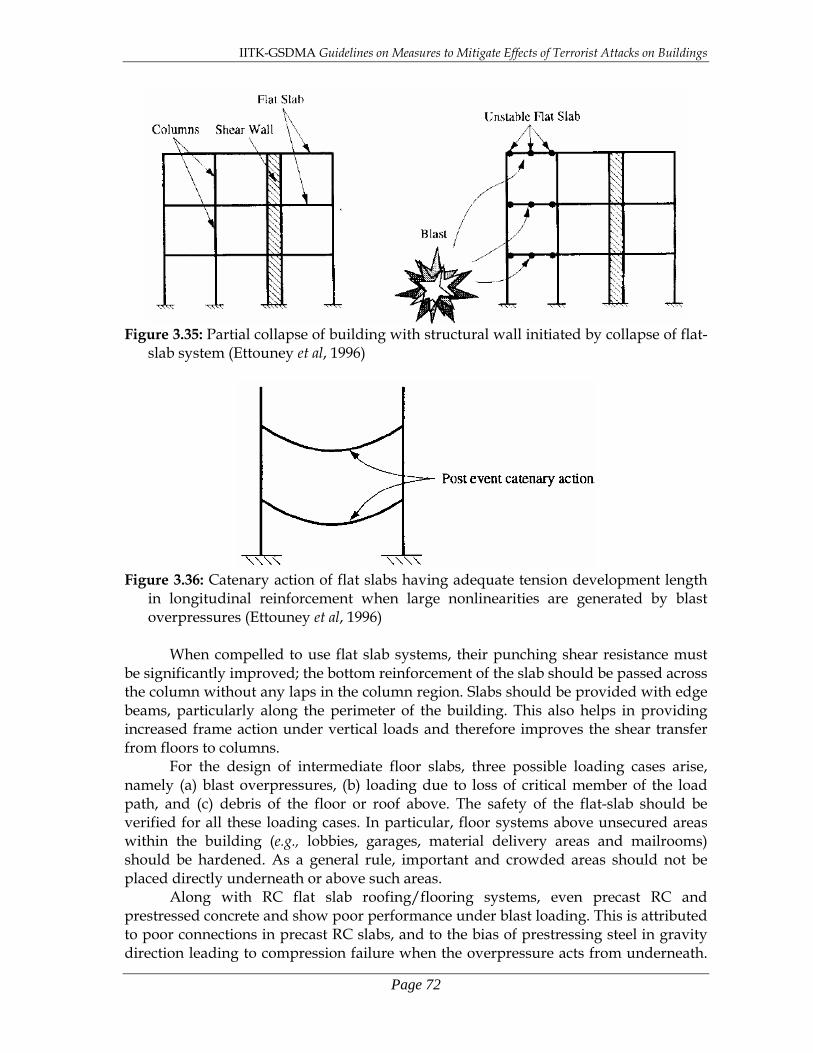
IITK-GSDMA Guidelines on Measures to Mitigate Effects of Terrorist Attacks on Buildings
Page 72
Figure 3.35: Partial collapse of building with structural wall initiated by collapse of flat-
slab system (Ettouney et al, 1996)
Figure 3.36: Catenary action of flat slabs having adequate tension development length
in longitudinal reinforcement when large nonlinearities are generated by blast overpressures (Ettouney et al, 1996)
When compelled to use flat slab systems, their punching shear resistance must
be significantly improved; the bottom reinforcement of the slab should be passed across the column without any laps in the column region. Slabs should be provided with edge beams, particularly along the perimeter of the building. This also helps in providing increased frame action under vertical loads and therefore improves the shear transfer from floors to columns.
For the design of intermediate floor slabs, three possible loading cases arise, namely (a) blast overpressures, (b) loading due to loss of critical member of the load path, and (c) debris of the floor or roof above. The safety of the flat-slab should be verified for all these loading cases. In particular, floor systems above unsecured areas within the building (e.g., lobbies, garages, material delivery areas and mailrooms) should be hardened. As a general rule, important and crowded areas should not be placed directly underneath or above such areas.
Along with RC flat slab roofing/flooring systems, even precast RC and prestressed concrete and show poor performance under blast loading. This is attributed to poor connections in precast RC slabs, and to the bias of prestressing steel in gravity direction leading to compression failure when the overpressure acts from underneath.

IITK-GSDMA Guidelines on Measures to Mitigate Effects of Terrorist Attacks on Buildings
Page 73
In steel-concrete composite floor/roof decks, usually light-weight concrete is used. If such a slab system is required to resist blast effects, its must be hardened. One way of achieving this is by replacing the light-weight concrete with normal-weight concrete. In addition for improved performance of these composite slab systems, the shear connectors between the steel sheet and decking concrete should be improved, and a higher gauge welded wire fabric should be used as reinforcement in the decking concrete.
Roof and floor slabs play a critical role in the lateral load resistance of the building. The total lateral force from the upper storeys is collected from the various vertical elements meeting it from above, and then distributes to the vertical elements underneath it in proportion to their lateral stiffness. Hence, for their role of uniting the vertical members, the roof and floors slabs are also called as roof and floor diaphragms. Under seismic shaking, the whole floor diaphragm is moved together in the lateral directions (Figure 3.37a) because all the vertical elements resting on the ground are shaken horizontally. However, under blast loading, only one side of the building can be loaded in the lateral direction, implying a large unsymmetrical loading on the building (Figure 3.37b). This makes it mandatory for the structural analysis procedure used for the design of the building to be a three-dimensional analysis. Also, the structural system of the building should not have unsymmetrical lateral load-resisting vertical elements. 3.4.3.3 Roof/Floor Beams versus Transfer Girders
Considering the poor performance of flat-slab systems, floor or roof slab systems are traditionally provided with the combined beam-slab systems. In moment frames, these beams grid in both directions and span over between the columns. Since such beams are integrally cast with the slab, the large area of the slab attracts large forces due to blast overpressures acting on them. The net overpressure on the slab can be acting from the bottom only (Figure 3.38a) or from the top & bottom (Figure 3.38b) depending on the location of blast, whether the overpressure is caused by the incident wave or the reflected wave, and whether the overpressure penetrates the fenestrations above the slab or not. For a blast on ground and close to the building, the slabs in the lower storey may experience more pressure from underneath than from above.
In either case, the beam-slab system is expected to undergo extreme loading of plastic actions due to the large overpressures due to blast effects. Thus, beams should be designed to sustain large plastic hinges including the reversal of overpressure in negative pressure stage. Hence, they should have longitudinal reinforcement on both top and bottom faces. Also, the longitudinal reinforcement should have adequate tension lap lengths. Further, to improve the ductility of these beams, the transverse stirrups provided in them must be closely-spaced 135º closed-hooks throughout the length. Since capacity design is adopted, the connections between beams and columns should be capable of withstanding effects of beam plastic moments and corresponding shears; the direction of moment may be considered to be in both hogging and sagging.

IITK-GSDMA Guidelines on Measures to Mitigate Effects of Terrorist Attacks on Buildings
Page 74
(a)
(b)
Figure 3.37: Deformation demands on the floor diaphragm under (a) seismic lateral forces, and (b) blast lateral forces (Ettouney et al, 1996)
Figure 3.38: Slabs attracting blast overpressures from (a) the bottom side only, and (b)
both bottom and top sides (Ettouney et al, 1996) Aesthetic and functional choices (e.g., a large arrival hall in the ground storey of
a hotel building, and need for a column-free auditorium space) sometimes result in a moment frame system with the vertical columns terminated at an intermediate or lower

IITK-GSDMA Guidelines on Measures to Mitigate Effects of Terrorist Attacks on Buildings
Page 75
level. And in such situations, the terminating columns rest on horizontal beams that are usually much large in size and having higher amount of reinforcement, than the other beams. These unusually heavy beams are called as transfer girders (Figure 3.39), and as their name suggests, they transfer the large column loads to the columns underneath it through flexure and shear. Transfer girders are used in arrival areas where large openings have to be created along the exterior perimeter of the building. These elements (e.g., floating columns and transfer girders) become targets for potential aggressors. When transfer girders fail, catastrophic failure of the structure can occur. Thus, their use must be strictly regulated if not prohibited. When compelled to use them, redundant transfer girders should be provided close to the exposed ones. Thus, closely spaced parallel frames on the exterior perimeter become necessary in buildings that are close to public streets.
Figure 3.39: Transfer girders are deeper beams supporting columns terminating above
them (adapted from Ettouney et al, 1996) When the transfer girders are subjected to large upward blast overpressures
(Figure 3.40a), they can form plastic hinges both at the ends and within the span (Figure 3.40b). This may lead to increased deformation of the transfer girder causing redistribution of loads. In turn, this redistribution may cause the beam above to undergo plastic actions while resisting the vertical column loads (Figure 3.40c). Sometimes, this redistribution may also lead to progressive collapse of the building. And, hence the use of transfer girders is limited only to very special circumstances, and when adopted, two measures have to be undertaken: 1. The frame (members and its connections) must be designed and detailed for the
design blast loading expected on the building. In doing so, the columns supporting the transfer girder should be made stronger than the transfer girder, in keeping with the capacity design concept as stated in section 3.4.1.1.
2. Progressive collapse analysis should be performed of the above designed building to investigate into the mode of failure. This is mandatory for buildings where the blast
Floating columns
Transfer Girders
Atrium Opening

IITK-GSDMA Guidelines on Measures to Mitigate Effects of Terrorist Attacks on Buildings
Page 76
loading on the transfer girder exceeds its capacity.
(a) (b)
(c)
Figure 3.40: Progressive collapse due to failure of transfer girders: (a) blast overpressures acting on the transfer girder, (b) formation of plastic hinges in the transfer girder, and (c) redistribution of forces leading to failure of the beam above (Ettouney et al, 1996)
3.4.3.4 Columns and Walls Vertical members are the most critical elements of the building. They must be
designed to resist two blast scenarios. Firstly, under blast overpressures generated by a blast away from the building, the façade of the building is subjected to a relatively low but uniform intensity of blast pressure. Secondly, under blast overpressures generated by a blast close to the building, they are subjected to relatively high and non-uniform intensity of blast pressure adjoining the blast, leading to two types of loads (Figure 3.41), namely direct force due to the pressure on the exposed surface area of the vertical members and indirect force due to the pressure on the exposed surface of other members in the structure (e.g., vertical pressure on the floor slabs causes uplift or tension force in the adjoining vertical members). Understandably, the former is very critical for the building façade and finishes, and to some extent on the safety of the overall structural system of the building, while the latter is very critical for the safety of the structural system particularly in the local area near the blast. However, the structure must be checked for safety against both the loads due to both away and close blasts.
Plastic hinges in transfer girder
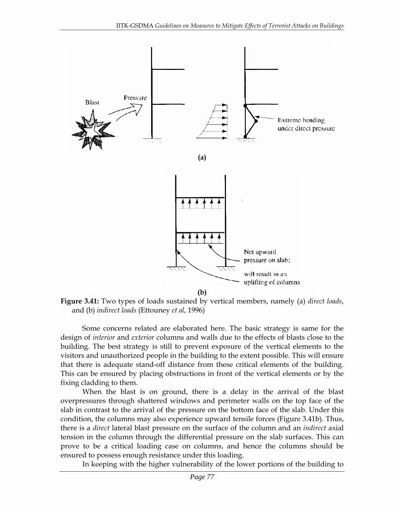
IITK-GSDMA Guidelines on Measures to Mitigate Effects of Terrorist Attacks on Buildings
Page 77
(a)
(b)
Figure 3.41: Two types of loads sustained by vertical members, namely (a) direct loads, and (b) indirect loads (Ettouney et al, 1996)
Some concerns related are elaborated here. The basic strategy is same for the
design of interior and exterior columns and walls due to the effects of blasts close to the building. The best strategy is still to prevent exposure of the vertical elements to the visitors and unauthorized people in the building to the extent possible. This will ensure that there is adequate stand-off distance from these critical elements of the building. This can be ensured by placing obstructions in front of the vertical elements or by the fixing cladding to them.
When the blast is on ground, there is a delay in the arrival of the blast overpressures through shattered windows and perimeter walls on the top face of the slab in contrast to the arrival of the pressure on the bottom face of the slab. Under this condition, the columns may also experience upward tensile forces (Figure 3.41b). Thus, there is a direct lateral blast pressure on the surface of the column and an indirect axial tension in the column through the differential pressure on the slab surfaces. This can prove to be a critical loading case on columns, and hence the columns should be ensured to possess enough resistance under this loading.
In keeping with the higher vulnerability of the lower portions of the building to

IITK-GSDMA Guidelines on Measures to Mitigate Effects of Terrorist Attacks on Buildings
Page 78
blast close to the building, columns and structural walls in the lower storeys should possess adequate strength and ductility. It is relatively easy to achieve high strength in columns and structural walls by increasing their cross-sectional area, longitudinal reinforcement and transverse reinforcement. However, it is not so easy to achieve ductility. It has been seen that columns and structural walls loaded with large axial stress possess poor ductility. Thus, their area of cross-section must be so chosen that the axial stress ratio is small. In RC columns and walls, this ratio must be kept at or just below the balanced axial load ratio (Figure 3.42). Further, as in the case of beams, the transverse reinforcement in columns and walls also should be closely spaced and have 135º hooks.
Figure 3.42: Columns with large compression have poor ductility; their axial stress ratio should be kept as small as possible.
Areas accessible by visitors should preferably be located along the exterior perimeter so that the blast overpressures can be vented out of the door and windows. To improve the hardening of the building, columns should be closely spaced and the beams should be so designed that redistribution of loads is ensured; large column spacing makes the beams flexible and hence decreases their capacity to redistribute loads when column failure occurs. An upper limit of 10m is considered reasonable. Interior structural walls also should be designed to resist the effects of a blast inside the building in areas that are accessible to visitors. Walls should be capable of developing the full flexural capacity. Hence, longitudinal bars should be anchored into the foundation at the bottom and into the roof slab. Additionally, interior walls should be designed to resist progressive collapse.
It is possible to improve the performance under blast loading of existing columns in the lower storey. They can be jacketed with steel plates to provide confinement to concrete in the column; this improves their shear capacity, ductility and strength. In case of steel columns, they could be encased in concrete.
M
P/Ag
RC
M
Steel Tens
ile L
oad
Tens
ile L
oad
Poor Ductility
Poor Ductility
P/Ag
Balanced Point
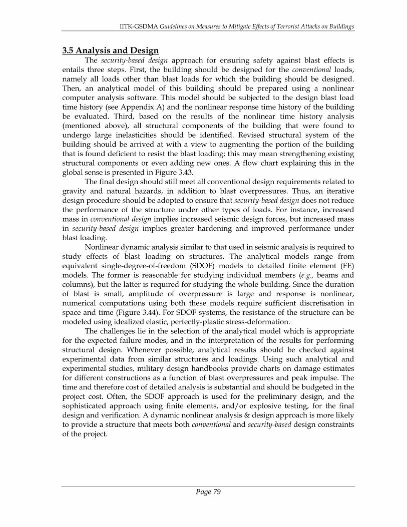
IITK-GSDMA Guidelines on Measures to Mitigate Effects of Terrorist Attacks on Buildings
Page 79
3.5 Analysis and Design The security-based design approach for ensuring safety against blast effects is
entails three steps. First, the building should be designed for the conventional loads, namely all loads other than blast loads for which the building should be designed. Then, an analytical model of this building should be prepared using a nonlinear computer analysis software. This model should be subjected to the design blast load time history (see Appendix A) and the nonlinear response time history of the building be evaluated. Third, based on the results of the nonlinear time history analysis (mentioned above), all structural components of the building that were found to undergo large inelasticities should be identified. Revised structural system of the building should be arrived at with a view to augmenting the portion of the building that is found deficient to resist the blast loading; this may mean strengthening existing structural components or even adding new ones. A flow chart explaining this in the global sense is presented in Figure 3.43.
The final design should still meet all conventional design requirements related to gravity and natural hazards, in addition to blast overpressures. Thus, an iterative design procedure should be adopted to ensure that security-based design does not reduce the performance of the structure under other types of loads. For instance, increased mass in conventional design implies increased seismic design forces, but increased mass in security-based design implies greater hardening and improved performance under blast loading.
Nonlinear dynamic analysis similar to that used in seismic analysis is required to study effects of blast loading on structures. The analytical models range from equivalent single-degree-of-freedom (SDOF) models to detailed finite element (FE) models. The former is reasonable for studying individual members (e.g., beams and columns), but the latter is required for studying the whole building. Since the duration of blast is small, amplitude of overpressure is large and response is nonlinear, numerical computations using both these models require sufficient discretisation in space and time (Figure 3.44). For SDOF systems, the resistance of the structure can be modeled using idealized elastic, perfectly-plastic stress-deformation.
The challenges lie in the selection of the analytical model which is appropriate for the expected failure modes, and in the interpretation of the results for performing structural design. Whenever possible, analytical results should be checked against experimental data from similar structures and loadings. Using such analytical and experimental studies, military design handbooks provide charts on damage estimates for different constructions as a function of blast overpressures and peak impulse. The time and therefore cost of detailed analysis is substantial and should be budgeted in the project cost. Often, the SDOF approach is used for the preliminary design, and the sophisticated approach using finite elements, and/or explosive testing, for the final design and verification. A dynamic nonlinear analysis & design approach is more likely to provide a structure that meets both conventional and security-based design constraints of the project.
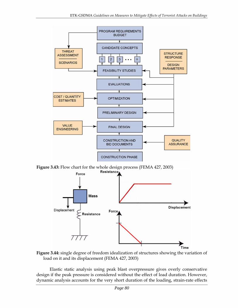
IITK-GSDMA Guidelines on Measures to Mitigate Effects of Terrorist Attacks on Buildings
Page 80
Figure 3.43: Flow chart for the whole design process (FEMA 427, 2003)
Figure 3.44: single degree of freedom idealization of structures showing the variation of
load on it and its displacement (FEMA 427, 2003)
Elastic static analysis using peak blast overpressure gives overly conservative design if the peak pressure is considered without the effect of load duration. However, dynamic analysis accounts for the very short duration of the loading, strain-rate effects

IITK-GSDMA Guidelines on Measures to Mitigate Effects of Terrorist Attacks on Buildings
Page 81
on materials, and the inertial effects; these substantially improve the response because by the time the large mass oscillates, the loading is greatly diminished. Furthermore, considering damage accounts for energy absorbed by the ductile systems through plastic deformation.
Damage computed from analysis can be classified into three levels, namely minor, moderate and major, depending on the peak ductility, support rotation and collateral effects. However, this quantitative classification is dependant on the type of structure and loading condition. Minor damage refers to failure of nonstructural elements (e.g., windows, doors, cladding and false ceilings); injuries may be expected, and fatalities are possible but unlikely. Moderate damage refers to localized failure ot structural elements that can be repaired; structural failure is limited to secondary structural members (e.g., beams, slabs and non-load-bearing walls). However, if the building has been designed for loss of primary members, localized loss of columns may be accommodated; injuries and possible fatalities are expected. And, major damage refers to loss of structural elements in the load path (e.g., columns or transfer girders); this may lead to loss of additional adjacent members. Extensive fatalities are expected. Building is usually not repairable. Generally, moderate damage is a reasonable design target for new construction.

IITK-GSDMA Guidelines on Measures to Mitigate Effects of Terrorist Attacks on Buildings
Page 82
This page is intentionally left blank.

IITK-GSDMA Guidelines on Measures to Mitigate Effects of Terrorist Attacks on Buildings
Page 83
Chapter 4 Guidelines for Existing Buildings
Including measures in existing buildings to mitigate the effects of terrorist attacks on them can be very tedious, time-consuming and expensive. Even after they are incorporated, their effectiveness is not as much as when the measures are incorporated in a new building. However, there is a large stock of buildings, particularly of buildings with critical functions, which need to be secured against potential terrorist attacks. This chapter describes the various steps to be taken to assess the vulnerability of existing buildings and provide measures in them to mitigate the effects of terrorist attack on them; these steps include hazard estimation, asset exposure, vulnerability assessment and risk evaluation. 4.1 Basic Anti-terrorism Strategies for Existing Buildings
Securing existing buildings against detrimental effects of terrorist attacks involves four strategies with increasing levels of penetration, namely (a) deter the attacker from accessing the target (passively by providing obstructions, or
actively by using tactical moves and weapon deployment), (b) detect the attacker before penetrating the site or entering the building access points
(actively through security surveillance), (c) deny the attacker from causing disproportionate damage to the assets (by building
hardening measures that reduce the damaging effects of blast, biological, chemical, nuclear and radiological attacks), and
(d) devalue the asset to little/no consequence of loss and thereby reduce charm for attackers to consider affecting the asset (by moving critical facilities/operations out of that asset).
While changes to existing buildings can be made to contribute to all the four of these strategies, the third strategy (i.e., to deny) may be a difficult and/or expensive one, particularly when structural hardening in item (c) above requires major modifications to the building structure as well as to the non-structural components. However, to undertake each of these above strategies, a clear understanding is required of the potential hazard, exposure to hazard, and vulnerability of the asset that is already in existence. 4.2 Mitigation Treatments for Different Hazards
The possible threats and hazards due to terrorist attacks are discussed in Chapter 1 of this document. Separate treatment is required to mitigate damaging effects of each of those threats/hazards. These are discussed in this section. 4.2.1 Explosion
The intensity of energy received at a point due to the explosion is inversely proportional to the cube of the stand-off distance from the point of blast. Therefore, increased stand-off distance is a direct measure of protection to the facility. Effective strategy for mitigating damaging effects of explosions requires attention to a number of

IITK-GSDMA Guidelines on Measures to Mitigate Effects of Terrorist Attacks on Buildings
Page 84
factors, including ease of access by the attacker to the facility, lack of barriers or shields to the facility, construction with no structural hardening, and avenues for attackers to easily conceal the devices in the near proximity of the facility.
4.2.2 Arson
The basic measures to reduce effects of arson on buildings include built-in systems for fire protection, fire detection, and fire-resistant construction techniques. Further, improved security systems are needed to ward off the threat, by preventing easy access to target, easy concealment of the incendiary device, and undetected initiation of a fire. Compliance with fire-related building codes and regular maintenance of the existing fire protection systems substantially help in diminishing the damaging effects of fire weapons used by the aggressors.
4.2.3 Armed Attack
The success of preventing armed attackers is contingent on the security posted at the building. An intelligent and strong security system can prevent access to aggressors, identify concealed weapons, and detect initiation of an attack. 4.2.4 Biological, Chemical, Nuclear and Radiological Attack
While drawing up clear strategies for mitigating detrimental effects of biological, chemical and radiological attacks, the following information is helpful. Altitude of release of the biological agent affects its dispersion; higher the release, greater is the dispersion. Light to moderate winds help disperse these agents, but high winds can destroy the aerosol clouds and hence their dispersion. Even presence of buildings and certain types of terrains can affect dispersion. Sunlight is detrimental for many types of bacteria and viruses.
On the other hand, higher temperatures cause evaporation of chemical aerosols in air and of chemical contamination on ground. High humidity enlarges the chemical aerosol particles and reduces the likelihood of inhalation. Precipitation dilutes the chemical agent, but leads to its dispersion. Wind disperses the chemical vapours, but makes the area on which the chemical can attack uncertain. Presence of buildings and certain types of terrains can change the dispersion patterns. Shielding by buildings is seen as an important way of protecting life and property from the ill effects of chemical contamination.
Similarly, the severity of the radiation attacks depends on duration of radiation release, distance of radiation release from the target, and amount of shielding between source and target. Understandably, since usually the first two parameters are not design quantities, amount of shielding is the focus of most mitigation efforts. Likewise, even for nuclear attacks also, while reduced duration of exposure to radiation and increased distance from the source are desirable, one may not have control on these quantities in the event of terrorist attacks. Here, again, shielding is the main strategy for minimizing the harmful effects of radiation. Since, light, heat and blast energy reduce logarithmically with increase in distance from the source, terrain forestation, obstruction structures, and large wall thickness are seen as some of the measures of shielding, so that the effects of nuclear attack (i.e., blast overpressure, radiation, and radioactive contamination) are absorbed or deflected.

IITK-GSDMA Guidelines on Measures to Mitigate Effects of Terrorist Attacks on Buildings
Page 85
4.2.5 Others Countering cyber-terrorism requires counter-intelligence and preempting moves by aggressors. In the absence of such innovations, critical computer networks/systems need to be isolated or allowed restricted entry. As in cyber-terrorism, inadequate security is also the reason of agri-terrorism. And, as in case of agri-terrorism, the trial-tested strategy for avoiding or mitigating agri-terrorism is physical security of the agricultural land. Protecting against unauthorized entry into a building is achieved by undertaking a building design that includes at least the standard measures of physical security. For more critical assets, a wider spectrum of security measures need to be incorporated, e.g., closed circuit television, access control points for visitors, and non-contact sensors for assisting in detection of aggressors. Similarly, unauthorized surveillance can be minimized by conducting the architectural design of the building in a way that the lines of sight are broken and acoustic collection is not possible by outsiders. 4.3 Asset Value
Some level of exposure to threat is present naturally in all assets, and lack of attention to the security aspect, adds to this exposure to the threat. There are two types of assets, namely tangible assets (e.g., occupants, buildings, facilities, equipment, activities, operations, and information), and intangible assets (e.g., processes, and reputation of a person/organization). Quantifying the value to the physical non-human components of the asset may relatively straightforward in tangible assets, but assigning value to potential loss of life of humans is difficult. Thus, design to mitigate effects of terrorist attack on structures needs to view separately the value of the physical non-human assets and of the number of persons under exposure of the attack.
Evaluating an asset is done in two steps, namely (1) defining and understanding the core functions and processes of the asset, and (2) identifying the infrastructure components (e.g., critical components, critical information systems & data, life safety systems & safe haven areas, and security systems). In step (1), it is envisaged to know (a) the primary services, (b) the critical activities undertaken in it, (c) the occupants & visitors to the asset, and (d) inputs received from agencies outside the asset, which determine the success of the asset in the event of a terrorist attack. In step (2), each of the components is critically studied from points of view of (a) location, amount & quantity, (b) impact & criticality in delivering the function, (c) level of preparedness built into the component including availability of backups & spares for replacement, and (d) potential injuries and deaths resulting from its failure.
The asset value quantification by FEMA [FEMA, 426] is done using a fuzzy logic integer scale (1 to 10). To begin with, the main features of the asset are listed. A typical list may include: site, architectural considerations, structural system, HVAC system, plumbing & gas system, electrical system, fire alarm & water sprinkler system, and communication system of the asset. Then, for each of these features, the personnel associated with that component are interviewed and an integer value is assigned on a scale of 10 to represent its effectiveness when a terrorist attack occurs. The descriptions of the choices on the 10-point integer are shown in Table 4.1.

IITK-GSDMA Guidelines on Measures to Mitigate Effects of Terrorist Attacks on Buildings
Page 86
Table 4.1: Asset value scale adopted by FEMA [from FEMA 426, 2003] Importance of component in the aftermath of terrorist attack
and continuing to undertake its functions Asset Value
Very High 10 High 8-9 Medium High 7 Medium 5-6 Medium Low 4 Low 2-3 Very low 1 Once asset value is assigned to each component, the vulnerable components of
the asset (with low ratings) that require upgrade are identified, and the process to upgrade them can be initiated. Sometimes, it may be difficult to upgrade a certain feature. For instance, the site of the asset may be ill-located, and it may require involvement of a wider section of the community to improve. 4.4 Vulnerability Assessment
Assessing the vulnerability of a building involves conducting an in-depth quantitative analysis of the building functions, systems and site characteristics to identify the weaknesses of the building including lack of redundancy. This information is useful in determining corrective actions that can be designed or implemented to reduce the detrimental effects of terrorist attacks. Usually, before undertaking the detailed vulnerability assessment, a rating of all buildings at the same site or within the whole campus is undertaken to understand the relative overall vulnerability rating of the buildings at that site/campus. This information is helpful in knowing the relative risks involved as well as in prioritizing the detailed vulnerability assessment activities.
4.4.1 Overall Vulnerability Rating
As in asset value quantification, the overall vulnerability rating is proposed by FEMA [FEMA, 426] using a fuzzy logic integer scale of 1–5. Rating is sought on seven aspects, namely: (1) level of visibility of asset to the terrorist, (2) importance value of asset, (3) value of target to terrorist, (4) access to target by terrorist, (5) threat of target being a hazard in itself, (6) site population capacity, and (7) potential for collateral damage in terms of mass casualties. This is rating done based on interviews of personnel associated with that building, and an integer value is assigned on a scale of 5 to represent its vulnerability to a terrorist attack. The descriptions of the choices on the 5-point integer scale are shown in Tables 4.2-4.8.
Once rating is assigned to each aspect, the net score (out of 35) provides the relative rating of the various buildings at a site or within a campus. Of course, this quick rating methodology assumes that the hazard level is the same for all buildings at that site. Should there be a differential hazard rating, it is necessary to conduct detailed vulnerability assessment to understand the relative risk being taken by different buildings.

IITK-GSDMA Guidelines on Measures to Mitigate Effects of Terrorist Attacks on Buildings
Page 87
Table 4.2: Level of visibility of asset to the terrorist [FEMA 426, 2003]
Table 4.3: Importance value of asset [FEMA 426, 2003]
Table 4.4: Value of target to terrorist [FEMA 426, 2003]

IITK-GSDMA Guidelines on Measures to Mitigate Effects of Terrorist Attacks on Buildings
Page 88
Table 4.5: Access to target by terrorist [FEMA 426, 2003]
Table 4.6: Threat of target being a hazard in itself [FEMA 426, 2003]
Table 4.7: Site population capacity [FEMA 426, 2003]

IITK-GSDMA Guidelines on Measures to Mitigate Effects of Terrorist Attacks on Buildings
Page 89
Table 4.8: Potential for collateral damage in terms of mass casualties [FEMA 426, 2003]
4.4.2 Detailed Vulnerability Assessment Here, the process of the hazard consequences is simulated using physical
quantitative models. Hazard is treated as a time varying function. Properties of the model are input based on field data measured/estimated. Principles of the chemical, biological, nuclear & radiological processes, of the mechanics of solids, and/or of the mechanics of heat transfer are employed to estimate quantitative response quantities of the asset. These quantities response quantities are analyzed to understand the implications of the terrorist attack. For instance, computer simulation damage results from detailed finite element analyses of buildings in Khobar Towers site (Dhahran, Saudi Arabia) are projected for a recall the 26 June 196 bombing (Figure 2.5). The intention of the simulations was to study the effect of stand-off distance.
For the purposes of risk assessment discussed in Section 4.4 of this document, the results of the detailed vulnerability assessment can be converted to a scale of 10.
4.5 Risk Evaluation and Reduction Risk is the net negative fallout of the prevalent hazard on the asset, the value of the asset, and the vulnerability of the asset, and summarized in the probability Eq.(4.1).
{ }ityVulnerabilValueHazard P RISK ××= (4.1) Clearly, comprehensive risk reduction is possible only by the systematic reduction of the negative consequences on each of the three fronts, namely hazard, value and vulnerability. While little improvement may possible on many an occasion with regard to reducing risk from the points of view of hazard and value, it is possible most of the time to build redundancy into the built environment and thereby reduce the risk to the extent possible. Redundancy is required at all levels, namely in systems that deter, detect and deny the terrorist attack, and at all times – before, during and after the attack. An analysis of the effect of lack of redundancy is shown in Figure 4.1.

IITK-GSDMA Guidelines on Measures to Mitigate Effects of Terrorist Attacks on Buildings
Page 90
Figure 4.1: Influence of redundancy on anti-terrorism resistance in buildings and
systems [FEMA 426, 2003] 4.5.1 Risk Assessment Each of the three contributors to risk, namely hazard, asset value and vulnerability are assigned a risk factor on a scale of 10. For hazard, 1 implies low or no probability of a terrorist attack, and 10 very high. For asset value, 1 implies low or no consequence of a terrorist attack on the continuance of the function of that asset in the aftermath of a terrorist attack, and 10 very high. For vulnerability, 1 implies low or no weakness in that component to resist a terrorist attack, and 10 very high. There are intermediate grey shades of the scale as shown in Table 4.9. Table 4.9: 10-point scale for assigning risk factor to contributors of risk [based on
FEMA 426, 2003] Level Hazard Asset Value Vulnerability Asset Value
Very high 10 High 8-9 Medium High 7 Medium 5-6 Medium Low 4 Low 2-3 Very low
probability of a terrorist attack
consequence of a terrorist attack
weakness to resist a terrorist attack
1
The risk factors assigned for each of the three contributors are multiplied and a total risk factor is arrived at. FEMA classifies net risk into three brackets, namely low risk if total risk factor is in the range 1-60, medium risk if total risk factor is in the range 61-175, and high risk if total risk factor is equal or more than 176, as shown in Table 4.10.

IITK-GSDMA Guidelines on Measures to Mitigate Effects of Terrorist Attacks on Buildings
Page 91
The above risk analysis can be conducted at the level of the overall asset, or even at the level of each component. Table 4.10: Risk factor classification as per FEMA [FEMA 426, 2003]
4.5.2 Risk Management Once risk is identified, it is important to manage risk, basically to reduce it. Three choices are available to the owner on future course of action (Figure 4.2), namely accept the prevalent risk, install reasonable mitigation measures, or undertake comprehensive mitigation measures including hardening of the building. This decision is crucial and is usually made at a level of the organization/system that includes persons who allocate funds.
Figure 4.2: Possible paths for treating risk [FEMA 426, 2003]
Once the intent is to reduce the risk, managing risk involves a five step process (Figure 4.3). These are: (a) identifying the goals of risk reduction (at component or overall level, and amounts of
risk reduction), (b) designing strategies to reduce risk (at the hazard, asset value and/or vulnerability
levels), (c) seeking allocation of budget for undertaking risk reduction (by sensitising the
funding authorities, applying for funding, and lobbying for funding), (d) receiving the funding (and allocating the available funds for the components stated
in the proposal for funding), and (e) building the risk reduction measures into the asset.

IITK-GSDMA Guidelines on Measures to Mitigate Effects of Terrorist Attacks on Buildings
Page 92
Figure 4.3: Steps involved in the process of managing risk [FEMA 426, 2003]
Step (b) above primarily deals with strengthening the building towards
upgrading its capacity to resist blast loads. A number of new techniques are available for upgrading structural systems or components of existing buildings, such as FRP systems for jacketing (Teng et al, 2002). A detailed account of the techniques is available in literature.

IITK-GSDMA Guidelines on Measures to Mitigate Effects of Terrorist Attacks on Buildings
Page 93
Chapter 5 Concluding Remarks
Considering the sensitive nature of the subject, public domain literature on the subject of terrorist attack on buildings is sparse in India. However, substantial information is available from other countries, in particular from the USA. The FEMA documents from the Government of USA provide comprehensive treatment of the subject. This document is a collation of the main concepts reported in the available books, reports and papers. The list of references used in preparing this document is placed under References at the end. 5.1 Summary
Buildings have been common targets for terrorist attacks. Making buildings secure from the negative effects of terrorist attacks needs a systematic treatment. Risk needs to be reduced within each of the three contributors to risk, namely hazard, asset value and vulnerability. This document provided a detailed treatment of the measures related to planning and design aspects of the mitigation measures in particular. Each building is seen to consist of three layers in it (Figure 5.1), and mitigation measures are possible at each of these layers.
Figure 5.1: Three layers at which terrorist attack on buildings can be mitigated [FEMA
452, 2005]

IITK-GSDMA Guidelines on Measures to Mitigate Effects of Terrorist Attacks on Buildings
Page 94
5.2 Challenges The subject of terrorist attack on buildings is yet to draw the undivided attention of the scientific community in India. The material presented in the preceding chapters of this document suggests the subject has evolved to the level of very fine details. However, many challenges still remain particularly in the Indian context, which require special impetus. Some of these challenges are recalled in this section. 5.2.1 Systemic Issues
Only now terrorism is being perceived as a major concern by the Government of India and by the Governments of some states. This perception needs percolate to all state levels, in a way that priority is placed on actions to mitigate the effects of terrorist attack on buildings. This increased priority should mean increased security administration, resulting in specific annual fund allocation for the express purpose, increased security personnel, and holistic building development strategies.
The building development strategies require changes in the building bye-laws related to site planning (covering land-use design, type of building, location of building on plot area, critical utilities of building, entry to site, surveillance, and parking), architectural considerations (covering architectural configuration, functional planning, and non-structural elements), and structural aspects (structural systems to be adopted, levels of hardening to be provided, progressive collapse, and local collapse). Such concepts related to terrorist attacks are currently not included in the urban bye-laws.
5.2.2 Technical Issues
Research and development related to terrorist attack on buildings needs to be stepped up. The Indian standard related to blast loading is IS:4991-1968. In the last four decades since its release, there has been an explosion of information on the subject. Such information needs to be included in the code, and hence IS:4991 requires an urgent revision. Also, the code employs a number of empirical formulae to describe the blast pressures on various geometries of buildings. These formulae may be reviewed in light of experimental evidence collected in the country since the release of the code in 1969. Further, generalized methodology for analyzing buildings of odd geometries may also be included in the form of guidelines.
The code (IS:4991) employs elasto-plastic method of estimating response of a structural element or frame-work of a building using the simplified equivalent single-degree-of-freedom system representation. This method needs a review particularly because of the limited ductility available in the buildings being built in the country, like the RC frame buildings with un-reinforced masonry infills. Expressions are provided therein for estimating natural period of individual structural components, and not of the building as a whole. Since the response of the building also needs to be estimated for undertaking the design, a comprehensive view is required on issues related to building response versus structural member response.
The current understanding of the non-linear behaviour of structures is quite advanced, owing to the major development of non-linear analysis tools. This development needs to be reflected in the procedures to be adopted for design of structures to resist blast loading, where non-linear actions are dominant. This also needs to find place in the code.
IITK-GSDMA Guidelines on Measures to Mitigate Effects of Terrorist Attacks on Buildings
Page 95
Progressive collapse and ductile detailing are two core essentials of buildings that need to resist blast loading. Experimental research needs to be undertaken to study the effectiveness of current detailing procedures in steel and RC buildings, with respect to blast loading.
A number of aspects related to structural hardening of the building from the point of view of blast loading are also relevant from the point of view of earthquake-resistant design of the building. The cross-relations between requirements for blast-resistant design and earthquake-resistant design also need to be studied.
…

IITK-GSDMA Guidelines on Measures to Mitigate Effects of Terrorist Attacks on Buildings
Page 96
This page is intentionally left blank.
IITK-GSDMA Guidelines on Measures to Mitigate Effects of Terrorist Attacks on Buildings
Page 97
Appendix A Blast Loading on Structures
Air explosions caused by bomb blasts lead to widespread damage to the built environment and thereby a major disaster. The damages can be both direct quantifiable losses as well as unquantifiable indirect losses. Losses can be classified as primary (implying loss of life and property) and as secondary (implying indirect loss of businesses and disruption of services). Blasts can be both above ground and below ground. Understandably, the impact of above ground blasts is more widespread on the built environment, which is predominantly built on ground and projecting vertically out of the ground. Knowledge on blasts at ground level or in air – their magnitude, mechanisms and effects on environment around, are essential to be able to reduce these losses. This chapter describes the basic physics of generation of shock waves in air, their transmission in air, its interaction with buildings and structures, and structural response of buildings. A.1 Weapons of Blast An explosion is a sudden release of energy, which can be caused by many sources, namely mechanical, chemical and nuclear in the increasing order of potential to cause damage. For instance, the explosives used in the 1995 Murrah Federal Building bombing in Oklahoma and the 1992 World Trade Center Building bombing in New York were of the second category, i.e., fertilizer-type (Ammonium Nitrate Fuel Oil explosive). Explosives are classified as low and high depending on the amount of energy released by them and the consequent damage caused by them (Figure A.1). The low explosives only burn, but do not detonate. They are set-off to deflagrate, rather than to detonate. They are primarily used as propellants, and have a cut-off detonation speed of about 1000m/s. An example of the low explosive is the black powder. On the other hand, the high explosive is designed to shatter, rather than to push. A description of the variety explosives along with the properties of these pure explosive compounds is available in literature (e.g., Henrych, 1979; Kinney, 1962). Depending on the type of explosion, the detonation speed can be in the range 1000-9000 m/s. Examples of the high explosives are dynamite and TNT.
Two significant by-products of an explosion are large amount of heat and extremely high overpressure in the air adjoining the explosive. For instance, a small amount of explosive of 1 gram of TNT alone produces 1120 calories of heat. Clearly, very high temperatures are feasible in the vicinity of the explosion. Hence, flammable material must be kept away from potentially hazardous areas where explosions can be expected. This report does not discuss details of (a) the types of explosives, be it mechanical, chemical or nuclear weapons of blast, and (b) the thermal aspects of explosions. Specialised literature may be referred to for information on the same. The following sections describe the air blast and its physical effects on the environment.

IITK-GSDMA Guidelines on Measures to Mitigate Effects of Terrorist Attacks on Buildings
Page 98
Figure A.1: Classification of explosives and their examples
(Source: http://www.fireandsafety.eku.edu/VFRE-99/Recognition/Low/low.htm)
A.2 Blast Loading During the explosion, there is a sudden expansion of the small amount of air surrounding the explosive, which causes increased pressure in that small area around the explosive. The pressure generated within the explosive is much higher than that around it. Even this relatively lower surrounding air pressure (which is itself orders of magnitude higher than the atmospheric pressure) is sufficient to cause extensive damage in the built environment around.
The magnitude of an explosion is stated in terms of equivalent weight of TNT (symmetric trinitrotoluene) that would have produced the same amount of energy. Thus, a 1 tonne (1T) yield of explosive implies that the detonation produced by it releases energy equal to that released by 1 tonne weight of TNT. It would be of interest to note that the nuclear bombs dropped by USA on Japan during the II World War were of size 15kT on Hiroshima (i.e., energy released is equal to that released by 15,000 tonne weight of TNT) and 20kT on Nagasaki. A.2.1 Overpressure and Its Time History
The highly pressurised air around the explosive expands and moves radially outward at a very high speed as a pressure wave front. The pressures and arrival times of the wave front at different propagation distances for two types of explosive charges, namely point-source and spherical-source charges respectively, for 1T yield of detonation, are shown in Tables A.1 and A.2. Inside and very close to the blast, the over-pressure (i.e., additional pressure above atmospheric pressure) can be as high as 200-1000 times the atmospheric pressure, while at distances about 10m from the explosion the pressures reduce to about 5-10 times the atmospheric pressures (Tables A.1 and A.2). The overpressure reduces to one-tenth of the atmospheric pressure only at distances of 100m from the source (Note 1 atmospheric pressure is equal to 0.1MPa).
The whole blast occurs in a very small amount of time, usually in milli-seconds. With time, again in milli-seconds, the overpressure of blast drops down rapidly and even becomes negative. The typical pressure variation of overpressure is shown in Figure A.2. There is a delay before the pressure acts. Initial pressure is positive in

IITK-GSDMA Guidelines on Measures to Mitigate Effects of Terrorist Attacks on Buildings
Page 99
nature (acting away from the blast), and quickly it reverses (acting towards the blast). The peak overpressure values are discussed in section A.2.1. The arrival time tx (i.e., delay of arrival) of the blast varies - 0.05-0.30 milli-seconds at 0.5m distance, about 5 milli-seconds at 10m, to 200 milli-seconds at 100m (Table A.1 and A.2). Similarly, the duration of the blast (including both positive and negative pressure durations) also varies - 2.5-15.0 milli-seconds at 0.5m distance, about 6 milli-seconds at 10m, to 25 milli-seconds at 100m (Table A.1 and A.2).
Thus, the blast can be seen as an impulse of high overpressure acting over a very small duration. An important characteristic of the blast impulse is the rapid drop in the overpressure. Literature (Kinney, 1962) indicates that this rate of decay of the overpressure p is usually exponential (Figure A.1a), and given by
( ) dttdatm ett1pp α−−= , (A.1)
where patm is the atmospheric pressure and α is the rate of decay parameter. Often, the momentum imparted to through the blast, called as the blast impulse I, is used to understand the possible extent of damage, and this quantity is obtained by integrating the instantaneous overpressure p over time increment dt over which the overpressure is occurring (Figure A.1b) as
∫=t
tx
pdtI . (A.2)
The over-pressure and arrival times and pressure impulse will be very different for higher sizes of explosives. The following scaling laws are to be applied to obtain the values of over-pressure P, arrival time tA and impulse I of a blast of W Tonnes of yield:
,
,
⎟⎟⎠
⎞⎜⎜⎝
⎛⋅=
⎟⎟⎠
⎞⎜⎜⎝
⎛⋅=
⎟⎟⎠
⎞⎜⎜⎝
⎛⋅=
31
1
31
1AA
31
1
WWII
andWWtt
WWPP
(A.3)
where 1P , At and 1I are the over-pressure, arrival time and impulse are the quantities associated with a explosive of 1Tonne of yield.

IITK-GSDMA Guidelines on Measures to Mitigate Effects of Terrorist Attacks on Buildings
Page 100
Table A.1: Details of pressure wave developed by a point-source blast (Source: Kinney, 1962)
Radial Distance
r (ft)
Mach Number of Shock Front
Peak Overpressure
p/patm
Arrival Time
tx (milli seconds)
r/tx
(ft/s)
Blast Duration
td (milli seconds) 5 28.800 970.000 0.06 89.000 14.8 10 9.960 115.000 0.30 33.000 14.5 15 5.560 35.000 0.85 19.000 14.0 20 3.820 16.000 1. 71 11.700 13.3 25 3.010 9.400 2.91 8.600 12.4 30 2.440 5.800 4.50 6.700 11.4 35 2.080 3.900 6.30 5.540 10.7 40 1.840 2.800 8.50 4.790 10.8 45 1.670 2.100 10.80 4.200 11.7 50 1.550 1.650 13.30 3.750 12.8 55 1.470 1.350 16.00 3.400 14.1 60 1.400 1.130 18.90 3.170 15.0 65 1.350 0.960 22.00 2.980 15.6 70 1.308 0.830 25.20 2.810 16.1 75 1.275 0.730 28.50 2.660 16.6 80 1.248 0.650 31.80 2.520 17.1 85 1.224 0.580 35.40 2.400 17.6 90 1. 202 0.520 39.20 2.300 18.0 95 1.184 0.470 43.10 2.210 18.4
100 1.170 0.430 47.00 2.140 18.8 105 1.159 0.400 50.90 2.070 19.2 110 1.149 0.370 54.80 2.010 19.6 115 1.140 0.350 58.70 1.958 19.9 120 1.133 0.330 62.60 1.920 20.2 125 1.126 0.310 66.50 1.887 20.5 130 1.119 0.292 70.40 1.854 20.8 135 1.112 0.275 74.30 1.823 21.1 140 1.106 0.259 78.30 1.794 21.4 145 1.100 0.244 82.30 1.766 21.7 150 1.094 0.230 86.30 1.740 22.0 155 1.089 0.218 90.30 1.716 22.2 160 1.085 0.208 94.30 1.695 22.4 165 1.082 0.200 98.40 1.676 22.6 170 1.079 0.192 102.50 1.659 22.8 175 1.076 0.185 106.60 1.643 23.0 180 1.073 0.178 110.70 1.628 23.2 185 1.071 0.171 114.80 1.614 23.4 190 1.068 0.164 118.90 1.601 23.5 195 1.065 0.157 123.00 1.588 23.6 200 1.062 0.151 127.10 1.576 23.8 205 1.060 0.146 131.20 1.564 23.9 210 1.058 0.141 135.40 1.553 24.1 215 1.056 0.136 139.60 1.542 24.2 220 1.054 0.131 143.80 1.532 24.3 225 1.053 0.127 148.00 1.533 24.4 230 1.051 0.123 152.20 1.513 24.5 235 1.050 0.120 156.40 1.504 24.6 240 1.048 0.116 160.60 1.495 24.6 245 1.047 0.113 164.80 1.487 24.7 250 1.046 0.110 169.00 1.479 24.7

IITK-GSDMA Guidelines on Measures to Mitigate Effects of Terrorist Attacks on Buildings
Page 101
Table A.2: Details of pressure wave developed by a TNT spherical-source blast (Source: Kinney, 1962)
Radial Distance
r (ft)
Mach Number of Shock Front
Peak Overpressure
p/patm
Arrival Time
tx (milli seconds)
r/tx (ft/s)
Blast Duration
td (milli seconds) 5 12.800 192.000 0.28 18.000 2.5
10 8.140 76.000 0.60 17.000 1.5 15 5.570 35.000 1.29 11.600 0.6 20 4.360 21.000 2.22 9.000 1.9 25 3.600 14.000 3.34 7.500 5.6 30 3.000 9.300 4.70 6.400 6.0 35 2.610 6.800 6.20 5.620 6.5 40 2.280 4.900 8.10 4.960 7.4 45 2.020 3.600 10.10 4.420 8.3 50 1.820 2.700 12.30 4.020 9.3 55 1.670 2.100 14.70 3.700 10.2 60 1.560 1.650 17.30 3.430 11.1 65 1.460 1.320 20.10 3.190 12.0 70 1.400 1.100 23.30 2.980 12.9 75 1.350 0.950 26.60 2.800 13.8 80 1.315 0.850 29.90 2.670 14.6 85 1.285 0.760 33.30 2.550 15.3 90 1.258 0.680 36.80 2.450 16.0 95 1.236 0.620 40.30 2.360 16.7
100 1.218 0.570 43.90 2.280 17.3 105 1.202 0.520 47.60 2.208 17.9 110 1.187 0.480 51.30 2.144 18.4 115 1.174 0.440 55.10 2.087 18.7 120 1.162 0.410 58.90 2.036 19.0 125 1.152 0.380 62.80 1.990 19.3 130 1.142 0.350 66.70 1.957 19.6 135 1.133 0.330 70.60 1.927 19.8 140 1.125 0.310 74.50 1.898 20.1 145 1.118 0.292 78.40 1.867 20.4 150 1.112 0.276 82.30 1.840 20.6 155 1.107 0.262 86.30 1.813 20.9 160 1.102 0.250 90.30 1.787 21.2 165 1.097 0.238 94.30 1.762 21.5 170 1.093 0.227 98.30 1.737 21.8 175 1.089 0.217 102.40 1.713 22.0 180 1.085 0.208 107.00 1.690 22.3 185 1.082 0.200 111.00 1.670 22.6 190 1.079 0.193 115.00 1.652 22.9 195 1.076 0.186 119.00 1.635 23.2 200 1.073 0.181 123.00 1.619 23.4 205 1.070 0.174 127.00 1.614 23.6 210 1.068 0.168 131.00 1.600 23.8 215 1. 066 0.162 135.00 1.587 23.9 220 1.064 0.156 138.00 1.575 24.1 225 1.062 0.151 144.00 1.564 24.2 230 1.060 0.146 148.00 1.554 24.3 235 1.058 0.141 152.00 1.545 24.4 240 1.056 0.137 156.00 1.537 24.4 245 1.055 0.133 160.00 1.530 24.5 250 1.054 0.129 165.00 1.523 24.6

IITK-GSDMA Guidelines on Measures to Mitigate Effects of Terrorist Attacks on Buildings
Page 102
(a)
(b) Figure A.2: Blast characteristics: (a) Overpressure time history with critical blast
parameters, and (b) Blast Impulse.
A.2.2 Propagation of Overpressure An ideal blast in air produces a compressed air wave front, which moves radially
outward at supersonic velocities and simultaneously expands, thereby causing a reduction in the overpressure (Figure A.3a). A surface or near-surface blast produces a hemispherical wave front. The speeds of these pressure wave fronts vary depending on distance from source (Tables A.1 and A.2). The speed os sound is normally about 340m/s. The shock wave front speeds are usually stated relative to the speed of sound modified to account for the compression of the air, and expressed in terms of Mach Number M of the shock wave front. The Mach Number varies from ~12-30 at the eye of
Positive pressure
Negative pressure
Time
Overpressure p Delay
Atmosphericpressure
patm
Arrival Time tx
Blast Duration td
Time
Delay Impulse I
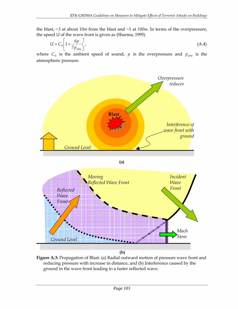
IITK-GSDMA Guidelines on Measures to Mitigate Effects of Terrorist Attacks on Buildings
Page 103
the blast, ~3 at about 10m from the blast and ~1 at 100m. In terms of the overpressure, the speed U of the wave front is given as (Sharma, 1995)
⎥⎦
⎤⎢⎣
⎡+=
atm0 p7
p61CU , (A.4)
where 0C is the ambient speed of sound, p is the overpressure and atmp is the atmospheric pressure.
(a)
(b) Figure A.3: Propagation of Blast: (a) Radial outward motion of pressure wave front and
reducing pressure with increase in distance, and (b) Interference caused by the ground in the wave front leading to a faster reflected wave.
Blast
Overpressurereduces
Ground Level
Interference ofwave front with
ground
Incident Wave Front Reflected
Wave Front
Moving Reflected Wave Front
Ground Level
Mach Stem

IITK-GSDMA Guidelines on Measures to Mitigate Effects of Terrorist Attacks on Buildings
Page 104
An important issue in propagation of these wave fronts of blasts in air is the interference of ground with the otherwise spherical wave front. The interaction of the blast wave front with the ground affects the geometry and characteristics of this expanding wave front. The incident wave front is reflected by the ground (Figure A.3b). The speed of this reflected wave front is faster than that of the incident wave front, and the reflected wave eventually overtakes the incident wave and forms an interference front called the Mach Stem. This Mach stem wave front attacks the built environment in the horizontal direction, in addition to the incident and reflected wave fronts that act at an inclination. The combined severity of the three wave fronts (namely incident, reflected and Mach stem) depends on the angle of inclination of the incident wave (Figure A.4). It is the most severe when the wave acts normal to the ground and least when it is parallel to the ground. Understandably, right underneath the blast, the shock wave front will impinge normal to the ground, while at far distances from the blast, the same shock wave front becomes parallel to the ground. This also implies that the reflected wave becomes weaker when the incident wave becomes parallel to the ground, and the Mach stem generated by this weak reflected wave also will be weaker. Hence, in such instances, the effective blast pressure on the buildings and structures is smaller. This information is extremely useful in planning the site of building; it is best to restrict the explosion as far away from the building as possible. Figure A.3: Angle of incidence on the ground of overpressure shock wave front reduces
with distance, and hence its reflected wave is weaker.
Blast
Angle ofIncidence
β

IITK-GSDMA Guidelines on Measures to Mitigate Effects of Terrorist Attacks on Buildings
Page 105
A.3 Blast Effects on Buildings A blast causes many effects: compression of surrounding air to high pressure levels is the most important effect. But there are other significant effects that need the attention while considering anti-terrorism measures. These include crater effects, shaking of the ground, thermal effects (like fires), dust, debris, and missile-effect due to some elements of the built environment being thrown into air as projectiles. A building needs to be protected against all these effects.
In case of nuclear bomb explosions, an additional complexity is added by the nuclear radiation, which in itself is a major hazard in both direct and indirect forms. Also, nuclear explosions release electromagnetic pulses which can affect electronic devices and equipment. This aspect also needs special attention. A.3.1 Crater Effects Blast that occur very near, at or under the Earth’s surface result in craters, large depression in the ground surface. The geometry of crater is shown in Figure A.4; the size of the depression depends on the size of the explosion. Usually, dimensions of a crater formed by a 1000 Tonne TNT explosion are obtained for different soil conditions and different heights or depths of burst, namely varying thicknesses of alluvium and hard rock. For all other cases, the scaling laws discussed in section A.2.1 are used. The volume of crater and other properties are available in literature (ASCE, 1985). Experiments showed that the most significant cratering occurs when the blast is near-surface (low elevation from the ground).
The main feature of this crater is the depth up to which the blast penetrates into the ground. The actual depth of the crater can be much below the apparent crater boundary, since some of the debris falls back into the crater. This feature is particularly important in determining the depth of embedment of underground utilities. Figure A.4: Geometry of a crater formed by near-surface explosion.
Blast Ejecta
Apparent CraterBoundary
True Carter Boundary
Original Ground Surface
Fallback
Height or depthof burst

IITK-GSDMA Guidelines on Measures to Mitigate Effects of Terrorist Attacks on Buildings
Page 106
A.3.2 Ground Shaking An explosion on underground causes direct shaking of the ground, due to the
overpressure of the blast slapping on the surface of the earth (Figure A.5). This is also called as the air slap induced ground shaking. However, an explosion slightly above ground causes both direct shaking of the ground and shaking of the ground due to the Mach Stem (formed by the interference of the reflected wave and the incident wave) that travels at supersonic speeds. The latter is referred to as the shock wave front induced ground shaking. Figure A.5: Shaking of earth due to above ground explosion results in two distinct
components of shaking.
The ground shaking produces causes inertial effects on the buildings and structures in addition to the blast that they need to face from the overpressures generated by the explosion. This requires that the design of structures be capable of resisting both these effects acting either simultaneously or individually but one immediately following the other. The resistance required in the structures in the neighbourhood of the explosion is in the form of ductility and toughness, and thus, appropriate design needs to be conducted to ensure that such structures possess these properties. Such a blast-resistant structure is therefore called a Hardened Structure.
A.3.3 Overpressure Loading on Different Structures Structures can be below ground, mounded or above ground (Figure A.6). Each of these choices of structural layout offers a different exposure condition to the blast overpressures and hence the quantum of force that each of them is subject to, is completely different. This also implies that the method of structural analysis to be adopted in each of these cases is different. Further, overtly simplified analysis, such as those with a single-degree-of-freedom system of analysis, is not possible in most cases, and detailed analysis methods are needed.
Blast
Mach Stem arising form Shock Wave Front
Air Slap Induced Shaking
Shock Wave Front Induced Shaking
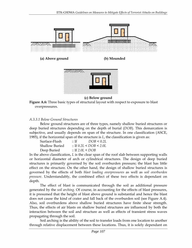
IITK-GSDMA Guidelines on Measures to Mitigate Effects of Terrorist Attacks on Buildings
Page 107
(a) Above ground (b) Mounded
(c) Below ground Figure A.6: Three basic types of structural layout with respect to exposure to blast
overpressures. A.3.3.1 Below Ground Structures Below ground structures are of three types, namely shallow buried structures or deep buried structures depending on the depth of burial (DOB). This demarcation is subjective, and usually depends on span of the structure. In one classification (ASCE, 1985), if the horizontal span of the structure is L, the classification is given as: Surface-Flush :: If DOB < 0.2L Shallow Buried :: If 0.2L < DOB < 2.0L Deep Buried :: If 2.0L < DOB In the above classification, L is the clear span of the roof slab between supporting walls or horizontal diameter of arch or cylindrical structures. The design of deep buried structures is primarily governed by the soil overburden pressure; the blast has little effect on the structure. On the other hand, the design of shallow buried structures is governed by the effects of both blast loading overpressures as well as soil overburden pressure. Understandably, the combined effect of these two effects is dependant on depth.
The effect of blast is communicated through the soil as additional pressure generated by the soil arching. Of course, in accounting for the effects of blast pressures, it is presumed that the height of blast above ground is substantial and hence the blast does not cause the kind of crater and fall back of the overburden soil (see Figure A.4). Also, soil overburdens above shallow buried structures have finite shear strength. Thus, the effects of air blasts on shallow buried structures are influenced by both the interaction between the soil and structure as well as effects of transient stress waves propagating through the soil. Soil arching is the ability of the soil to transfer loads from one location to another through relative displacement between these locations. Thus, it is solely dependant on

IITK-GSDMA Guidelines on Measures to Mitigate Effects of Terrorist Attacks on Buildings
Page 108
the properties of the soil. This property of the soil to undergo arching allows it to redistribute the loads on a buried roof slab from the flexible center span location to the relatively stiffer supports of columns and structural walls. Thus, soil arching tends to subject the buried structure to a vertical compression mode of failure. When the structure is relatively stiffer, the soil arching effect may not be achieved when the soil shear capacity is exceeded under large blast overpressures; in such instances, no redistribution takes place. Analytical expressions are presented in literature for the pressure at the top of a shallow buried structure accounting for the above effects (e.g., ASCE, 1985; Stainley and Sibley, 1962). The most generalized expression that is known to have given reasonable estimates of vertical pressures qP on the top of the buried structures is (ASCE, 1985):
( )( )a
ba1K2
0sq
0
e PP+−
=φtan
, (A.5) where
0sP = Overpressure at the ground surface,
0K = Coefficient of lateral earth pressure at rest, φ = Angle of internal friction of soil, a = Factor relating the length of the structure to its span length L, and b = Factor relating the depth of burial of the structure to its span length L. The variations of the vertical pressures qP on shallow buried rectangular and cylindrical surfaces with depth of burial are shown in Figure A.7. Clearly, soil arching is more prominent in granular soils than in cohesive soils. The arched portion of the soil actually behaves as part of the buried structure. Studies by numerous investigators on soil arching effect conclude that load distributions considering soil arching are more beneficial in the design of buried structures, i.e., they result in more economical structures because the effective force on the buried considering soil arching is smaller than that without it. However, for this very reason, in many designs, this effect is dropped deliberately to seek a conservative design.
The corresponding lateral pressures qlP are obtained using 0K , the coefficient of lateral earth pressure at rest, as
q0ql PKP = . (A.6) The pressure wave incident on the buried structure produces a very complex pressure distribution on the structure (e.g., Figure A.8). However, for the purposes of design, both vertical and lateral pressures generated by the blast are assumed to be constant on the buried structure (Figure A.9). And, design aids are prepared for the stress-resultants (like bending moment and axial thrust/tension for different structures (e.g., Figures A.10 and A.11).

IITK-GSDMA Guidelines on Measures to Mitigate Effects of Terrorist Attacks on Buildings
Page 109
Figure A.7: Influence of depth of burial on pressure acting on structures of different shapes (ASCE, 1985)
Figure A.8: Pressure distribution around a cylindrical buried structure due to an
incident pressure wave arriving from the surface (ASCE, 1985)
(a) Arch (b) Cylinders
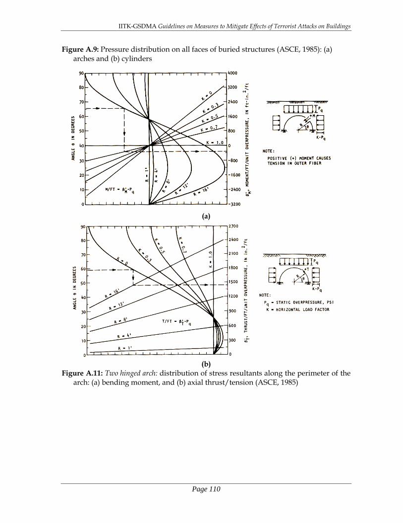
IITK-GSDMA Guidelines on Measures to Mitigate Effects of Terrorist Attacks on Buildings
Page 110
Figure A.9: Pressure distribution on all faces of buried structures (ASCE, 1985): (a) arches and (b) cylinders
(a)
(b) Figure A.11: Two hinged arch: distribution of stress resultants along the perimeter of the
arch: (a) bending moment, and (b) axial thrust/tension (ASCE, 1985)

IITK-GSDMA Guidelines on Measures to Mitigate Effects of Terrorist Attacks on Buildings
Page 111
(a)
(b) Figure A.12: Fixed arch: distribution of stress resultants along the perimeter of the arch:
(a) bending moment, and (b) axial thrust/tension (ASCE, 1985)
In surface-flush buried structures, the loading on the structures is further complicated by the reflection of the downward pressure wave at the surfaces of the buried structure. This reflection causes an increases effective pressure rP on the surface of the buried structure, up to about twice that of the incident wave iP , as given by

IITK-GSDMA Guidelines on Measures to Mitigate Effects of Terrorist Attacks on Buildings
Page 112
⎪⎩
⎪⎨⎧
>
≤⎟⎟⎠
⎞⎜⎜⎝
⎛−=
Dia
DD
ir
ttIFPC
ttIFtt2PP
::
:: , (A.7)
where Dt = 12D/C,
D = Thickness of the roof surface, C = Compression wave velocity, and
aC = Factor for soil arching on effective pressure on buried surface. However, this increased pressure acts only for a short period of time Dt (Figure A.10). For normal thicknesses of roofs of buried structures, Dt can be very small and therefore the increased pressure is usually neglected. For blasts of yield less than 50kT, the factor
aC improves the estimate pressure estimate. However, for blasts of higher yields, the effective pressure may be taken as the incident pressure, i.e., aC may be taken as 1.0.
(a) DOB < 0.2L (b) DOB > 0.2L
Figure A.10: Effective pressure on buried structures (ASCE, 1985): (a) DOB < 0.2L and (b) DOB > 0.2L.
The effects of blast pressures on surface-flush structures become complicated when the blast causes a crater and fall back of the overburden soil (see Figure A.4). Estimation of effective pressures on such structures due to blast and the consequent structural analysis requires special investigations. A.3.3.2 Mounded Structures Mounded structures are those are typically built at ground level, but covered with an elevated mound of soil around it just to make its top surface flush with soil (Figure A.11). The loads levels sustained by mounded structures are expected to be bounded by those sustained by below ground and above ground structures. However, significant effects occur due to the reflection of the incident wave on the inclined surfaces. Further, as the Mach Stem of the shock wave front crossed the mound, significant drag effects are experienced. As in the case of above ground structures subjected to wind effects, the windward side of the mound experiences positive pressures, while the leeward side experiences suction pressure.
The above two effects are observed to be prominent even when the soil mound is developed with gentle slopes of 1:4 or milder. Soil arching effects are considered not to
2Pi
Pi
2Pi
Pi
tD tD

IITK-GSDMA Guidelines on Measures to Mitigate Effects of Terrorist Attacks on Buildings
Page 113
occur in such mounded structures. The non-uniformity associated with the depth of burial and geometry of the mound does not allow the development of a single generalized but simple expression for the pressure distribution along the surface of the mounded structure. Expressions for pressures need to be developed for individual surfaces of the structure based on the principles of mechanics of the motion of shock wave front and its reflection within the soil mass. Thus, high-precision analysis is required to be conducted for mounded structures.
(a)
(b) (c) Figure A.11: Different geometries of mounded structures (ASCE, 1985): (a) mounded
arch or dome, (b) mounded rectangular structure, and (b) mounded cylinder A.3.3.3 Above Ground Structures Structures that come in the domain of the blast, are subjected to three types of pressure, described below: (a) Overpressure:: the air blast pressure-time history that occurs in the free-field; it
usually varies from 100-1000 times the atmospheric pressure, i.e., 20-100MPa; (b) Reflected Pressure:: the increased pressure that occurs when the propagating blast
wave front strikes a surface, reflects back, and interferes with the original wave front; it varies from 1-8 times the overpressure depending on both the overpressure itself and the inclination of reflecting ground with respect to incident wave (Figure A.12); and
(c) Dynamic Pressure:: the pressure that occurs behind the shock wave front, which causes drag and lift on structures that come in the path of such a flow; this depends on profile of the obstructing structure and the direction of wind with respect to the faces of the obstructing structure (Table A.3).
Thus, the amplitudes of these three pressure systems are dependant on (a) the height of charge with respect to the ground, and amount of charge of the blast, (b) the size, shape
Blast
Suction Pressureon Leeward side
Mach Stem arising form Shock Wave Front
Positive Pressure on Windward side

IITK-GSDMA Guidelines on Measures to Mitigate Effects of Terrorist Attacks on Buildings
Page 114
and orientation of the structure in focus, and (b) the location and orientation of other surfaces in the vicinity (e.g., Figure A.13). Figure A.12: Reflected Pressure: Reflection factor (ratio of reflected pressure to incident
pressure) variation with inclination of surface of indicence with respect to incident wave (ASCE, 1985)
Table A.3: Dynamic Pressure: Drag and lift coefficients for different profiles and direction of wind (ASCE, 1985)
Structure Profile and Wind Direction Cd CL 2.0 0.0 2.0 0.0 I 2.0 0.0
I 1.8 0.0 L 2.0 0.3
1.8 2.1
L 2.0 -0.1 L 1.6 -0.5
T 2.0 0.0 T 2.0 -1.2
II 2.2 0.0
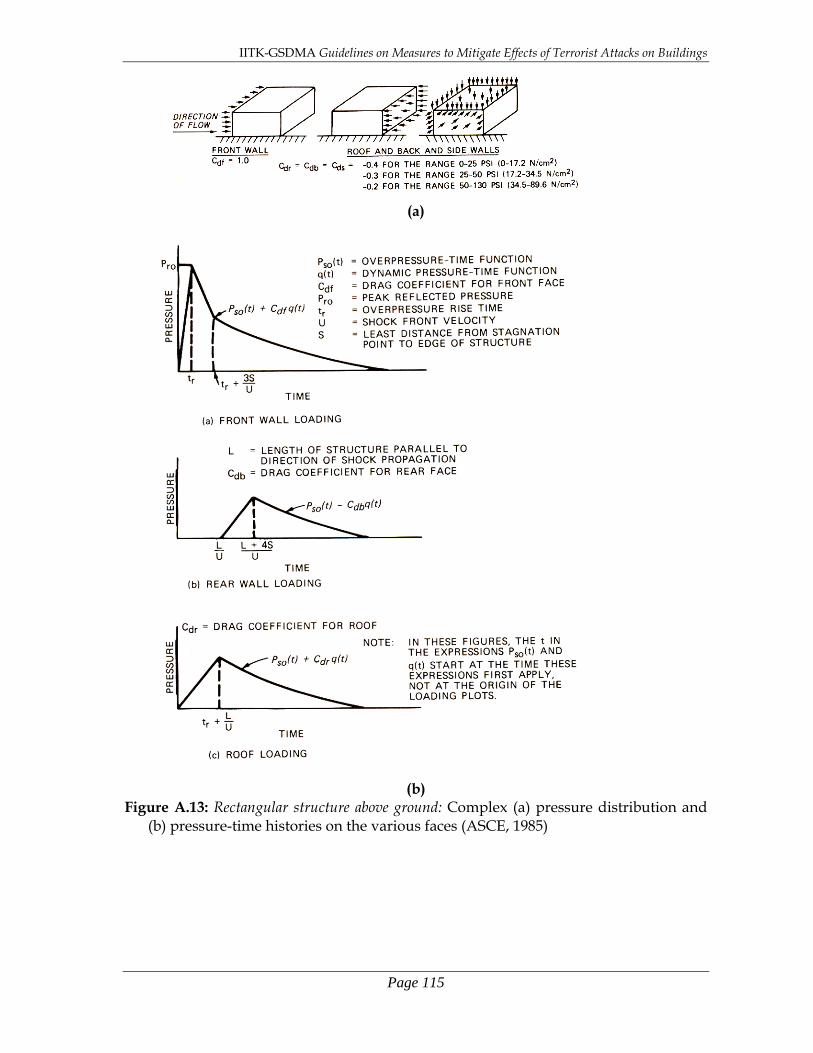
IITK-GSDMA Guidelines on Measures to Mitigate Effects of Terrorist Attacks on Buildings
Page 115
(a)
(b) Figure A.13: Rectangular structure above ground: Complex (a) pressure distribution and
(b) pressure-time histories on the various faces (ASCE, 1985)

IITK-GSDMA Guidelines on Measures to Mitigate Effects of Terrorist Attacks on Buildings
Page 116
A.3.4 Other Effects Large amount of heat generated during the explosion (~1120 calories per gm of TNT) is a threat to the exterior as well as interior of the built environment. While architects need to review the architectural features for their flammability under such conditions, the structural engineers involved in the design of the structures need to consider the safety of the structures under the thermal demand imposed by the heat generated during the explosion. Inclusion of temperature effects in the structural analysis and appropriate selection of materials with smaller latent heat during the design and detailing, are crucial to the safety of the structure. Clearly, this is a major concern in nuclear explosions. The net pressure on structures due to the blast causes two main effects. First, it disconnects all facia work and decorative items affixed to the surface of the structure. Second, it causes extra load on the structure depending on the area exposed to the increased pressure. While the former is an item of control in architectural planning and design, the latter is an item within the purview of the structural designers.

IITK-GSDMA GUIDELINES
on MEASURES TO MITIGATE EFFECTS OF TERRORIST ATTACKS ON BUILDINGS JULY 2007

IITK-GSDMA GUIDELINES on MEASURES TO MITIGATE EFFECTS OF TERRORIST ATTACKS ON BUILDINGS
CHAPTER 1: INTRODUCTION
IITK-GSDMA GUIDELINES on MEASURES TO MITIGATE EFFECTS OF TERRORIST ATTACKS ON BUILDINGS
CHAPTER 2: POSSIBLE DAMAGE TO BUILDINGS UNDER BLAST LOADING

IITK-GSDMA GUIDELINES on MEASURES TO MITIGATE EFFECTS OF TERRORIST ATTACKS ON BUILDINGS
CHAPTER 3: GUIDELINES FOR NEW BUILDINGS

IITK-GSDMA GUIDELINES on MEASURES TO MITIGATE EFFECTS OF TERRORIST ATTACKS ON BUILDINGS
CHAPTER 4: GUIDELINES FOR EXISTING BUILDINGS

IITK-GSDMA GUIDELINES on MEASURES TO MITIGATE EFFECTS OF TERRORIST ATTACKS ON BUILDINGS
CHAPTER 5: CONCLUDING REMARKS

IITK-GSDMA GUIDELINES on MEASURES TO MITIGATE EFFECTS OF TERRORIST ATTACKS ON BUILDINGS
APPENDIX A: BLAST LOADING ON STRUCTURES