Index - Section 40L - Process Controls And · PDF fileIndex - Section 40L ITEM PAGES ... High...
40
www.cranepumps.com USA: (937) 778-8947 • Canada: (905) 457-6223 • International: (937) 615-3598 A Crane Co. Company Index - Section 40L ITEM PAGES Bulletin 4500 Typical Architect / Engineer Specifications - 4500 Series..................................................................................... 1 Guide Bearing and Shaft Selection 4500 Series .................................................................................................. 2 Shaft and Guide Bearing Assemblies 4500 Series ............................................................................................... 3 - 4 Pump Selection Data ............................................................................................................................................ 5 Pump Assembly, Fig. 4501, 4511, & 4521 ............................................................................................................ 6 Pump Dimensions - Fig. 4501, 4511 & 4521, Simplex Units ................................................................................ 7 Pump Dimensions - Fig. 4501, 4511 & 4521, Duplex Units.................................................................................. 8 Pump Dimensions - Fig. 4560, Simplex Units ...................................................................................................... 9 Pump Dimensions - Fig. 4560, Duplex Units ........................................................................................................ 10 Selection Curves, Fig. 4500, 3500RPM, 1750RPM, 1150RPM, & 870RPM ........................................................ 11 - 12 Performance Curves, Fig. 4511, Sizes: 1¼S & 1½S, 1150RPM .......................................................................... 13 Performance Curves, Fig. 4511, Sizes: 1½M & 2S, 1150RPM ............................................................................ 14 Performance Curves, Fig. 4511, Sizes: 2M & 3S, 1150RPM ............................................................................... 15 Performance Curves, Fig. 4511 & 4521, Sizes: 3MD & 1½L, 1150RPM .............................................................. 16 Performance Curves, Fig. 4521, Sizes: 4MD & 5MD, 1150RPM ......................................................................... 17 Performance Curves, Fig. 4521, Sizes: 5MSD & 6MD, 1150RPM ....................................................................... 18 Performance Curves, Fig. 4521, Sizes: 6MLD, 1150RPM ................................................................................... 19 Performance Curves, Fig. 4565, 4566 & 4568, Sizes: 4x4x12 DV & 6x4x12 DV, 1150RPM ............................... 20 Performance Curves, Fig. 4565, 4566 & 4568, Sizes: 6x6x12 DV & 8x6x12 DV, 1150RPM ............................... 21 Performance Curves, Fig. 4565, 4566 & 4568, Sizes: 8x8x12 DV & 10x10x12 DV, 1150RPM ........................... 22 Performance Curves, Fig. 4565, 4566 & 4568, Sizes: 10x10x12 DV, 870RPM ................................................... 23 Performance Curves, Fig. 4501, Sizes: 1" & 1½", 1750RPM ............................................................................... 24 Performance Curves, Fig. 4501 & 4511, Sizes: 2½" & 1¼S, 1750RPM .............................................................. 25 Performance Curves, Fig. 4511, Sizes: 1½S & 1½M, 1750RPM ......................................................................... 26 Performance Curves, Fig. 4511, Sizes: 2S & 2M, 1750RPM ............................................................................... 27 Performance Curves, Fig. 4511, Sizes: 3S & 3MD, 1750RPM............................................................................. 28 Performance Curves, Fig. 4521, Sizes: 4MD & 5MD, 1750RPM ......................................................................... 29 Performance Curves, Fig. 4511 & 4521, Sizes: 4S & 5MS, 1750RPM ................................................................ 30 Performance Curves, Fig. 4521, Sizes: 5MSD & 6MD, 1750RPM ....................................................................... 31 Performance Curves, Fig. 4521, Size: 6MLD & 1½L, 1750RPM.......................................................................... 32 Performance Curves, Fig. 4565, 4566 & 4568, Sizes: 4x4x12 DV & 6x4x12 DV, 1750RPM ............................... 33 Performance Curves, Fig. 4565, 4566 & 4568, Sizes: 6x6x12 DV & 8x6x12 DV, 1750RPM ............................... 34 Performance Curves, Fig. 4565, 4566 & 4568, Sizes: 8x8x12 DV, 1750RPM ..................................................... 35 Performance Curves, Fig. 4511H, Sizes: 1" & 1½", 3500RPM ............................................................................ 36 Performance Curves, Fig. 4511H, Sizes: 1¼S & 1½S, 3500RPM ....................................................................... 37 Performance Curves, Fig. 4511H, Sizes: 2S & 3MD, 3500RPM .......................................................................... 38 Large Sump or Drainage Pumps Bulletin 4500
Transcript of Index - Section 40L - Process Controls And · PDF fileIndex - Section 40L ITEM PAGES ... High...

www.cranepumps.com
USA: (937) 778-8947 • Canada: (905) 457-6223 • International: (937) 615-3598A Crane Co. Company
Index - Section 40L
ITEM PAGES
Bulletin 4500
Typical Architect / Engineer Specifi cations - 4500 Series..................................................................................... 1
Guide Bearing and Shaft Selection 4500 Series .................................................................................................. 2
Shaft and Guide Bearing Assemblies 4500 Series ............................................................................................... 3 - 4
Pump Selection Data ............................................................................................................................................ 5
Pump Assembly, Fig. 4501, 4511, & 4521 ............................................................................................................ 6
Pump Dimensions - Fig. 4501, 4511 & 4521, Simplex Units ................................................................................ 7
Pump Dimensions - Fig. 4501, 4511 & 4521, Duplex Units .................................................................................. 8
Pump Dimensions - Fig. 4560, Simplex Units ...................................................................................................... 9
Pump Dimensions - Fig. 4560, Duplex Units ........................................................................................................ 10
Selection Curves, Fig. 4500, 3500RPM, 1750RPM, 1150RPM, & 870RPM ........................................................ 11 - 12
Performance Curves, Fig. 4511, Sizes: 1¼S & 1½S, 1150RPM .......................................................................... 13
Performance Curves, Fig. 4511, Sizes: 1½M & 2S, 1150RPM ............................................................................ 14
Performance Curves, Fig. 4511, Sizes: 2M & 3S, 1150RPM ............................................................................... 15
Performance Curves, Fig. 4511 & 4521, Sizes: 3MD & 1½L, 1150RPM .............................................................. 16
Performance Curves, Fig. 4521, Sizes: 4MD & 5MD, 1150RPM ......................................................................... 17
Performance Curves, Fig. 4521, Sizes: 5MSD & 6MD, 1150RPM ....................................................................... 18
Performance Curves, Fig. 4521, Sizes: 6MLD, 1150RPM ................................................................................... 19
Performance Curves, Fig. 4565, 4566 & 4568, Sizes: 4x4x12 DV & 6x4x12 DV, 1150RPM ............................... 20
Performance Curves, Fig. 4565, 4566 & 4568, Sizes: 6x6x12 DV & 8x6x12 DV, 1150RPM ............................... 21
Performance Curves, Fig. 4565, 4566 & 4568, Sizes: 8x8x12 DV & 10x10x12 DV, 1150RPM ........................... 22
Performance Curves, Fig. 4565, 4566 & 4568, Sizes: 10x10x12 DV, 870RPM ................................................... 23
Performance Curves, Fig. 4501, Sizes: 1" & 1½", 1750RPM ............................................................................... 24
Performance Curves, Fig. 4501 & 4511, Sizes: 2½" & 1¼S, 1750RPM .............................................................. 25
Performance Curves, Fig. 4511, Sizes: 1½S & 1½M, 1750RPM ......................................................................... 26
Performance Curves, Fig. 4511, Sizes: 2S & 2M, 1750RPM ............................................................................... 27
Performance Curves, Fig. 4511, Sizes: 3S & 3MD, 1750RPM ............................................................................. 28
Performance Curves, Fig. 4521, Sizes: 4MD & 5MD, 1750RPM ......................................................................... 29
Performance Curves, Fig. 4511 & 4521, Sizes: 4S & 5MS, 1750RPM ................................................................ 30
Performance Curves, Fig. 4521, Sizes: 5MSD & 6MD, 1750RPM ....................................................................... 31
Performance Curves, Fig. 4521, Size: 6MLD & 1½L, 1750RPM.......................................................................... 32
Performance Curves, Fig. 4565, 4566 & 4568, Sizes: 4x4x12 DV & 6x4x12 DV, 1750RPM ............................... 33
Performance Curves, Fig. 4565, 4566 & 4568, Sizes: 6x6x12 DV & 8x6x12 DV, 1750RPM ............................... 34
Performance Curves, Fig. 4565, 4566 & 4568, Sizes: 8x8x12 DV, 1750RPM ..................................................... 35
Performance Curves, Fig. 4511H, Sizes: 1" & 1½", 3500RPM ............................................................................ 36
Performance Curves, Fig. 4511H, Sizes: 1¼S & 1½S, 3500RPM ....................................................................... 37
Performance Curves, Fig. 4511H, Sizes: 2S & 3MD, 3500RPM .......................................................................... 38
Large Sump or Drainage Pumps
Bulletin 4500
www.cranepumps.com
USA: (937) 778-8947 • Canada: (905) 457-6223 • International: (937) 615-3598A Crane Co. Company
This page intentionally left blank
www.cranepumps.com
SECTION
PAGE
DATE
USA: (937) 778-8947 • Canada: (905) 457-6223 • International: (937) 615-3598A Crane Co. Company
1
40-L
Large Sump or Drainage Pumps
12/10
Typical Architect/Engineers Specifi cations
Series: 4500
General
Furnish and install, as shown on the plans _____ Deming
Fig. 4500 Series Heavy Duty Vertical Sump Pumps,
each pump to be capable of pumping ____GPM when
operating against a total pumping head of _____ feet
at temperature, specifi c gravity and viscosity indicated.
Each pump shall operate at _______ RPM and shall
have _______ percent effi ciency at the design point.
Shut-off head shall be not less than _______ feet. Pump
shall be (clockwise)(counter-clockwise) rotation when
viewed from the driver. The unit shall be designed for
installation in a sump _______ feet deep and furnished
with (above)(below) plate discharged of size indicated.
Construction Details
The pump liquid end including casing, impeller, suction
head, strainer and bearing housing shall be of cast iron
having minimum tensile strength of 30,000 lbs. Impeller
shall be semi-open type secured to shaft with key,
washer and lock nut and shall be fully adjustable, without
dismantling the pump, by means of an adjusting nut
located above the thrust bearing in the motor support.
Flanged column pipe shall be full weight steel pipe with
a machined register fi t at all assembly points to assure
concentric alignment. Pump shaft shall be of a high
grade carbon steel of suffi cient size to transmit required
horsepower.
Replaceable shaft guide bearings, of material suitable
for the liquid being pumped, shall be contained in
precision machined bearing housings; fl anged for
machined register fi t in column pipe fl anges and spaced
on recommended bearing centers, but not to exceed
5-foot centers. Bottom bearing assembly shall include
choker ring. Suitable lubrication shall be provided to each
shaft guide bearing.Cast iron motor support, mounted
on heavy steel support plate, shall align the motor with
column pipe and shafting. High capacity ball thrust
bearing, in waterproof housing, shall be mounted in the
motor support. Bearing shall be grease lubricated with
provision for purging old grease from bearing housing.
The pump assembly shall include a heavy steel support
plate _______ inches diameter, for mounting on a pit
_______ inches diameter. Pump discharge pipe shall
extend above the plate and shall be supported from
the plate by two lock nuts. Duplex pump sump cover
shall include a manhole 11 x 15 inches, or larger with
cover and with _______ inch (fl anged)(threaded) vent
connection.
Control
For single pump, a suitable fl oat switch shall be mounted
on support plate and shall be operated by a guided
copper plated fl oat. Switch shall operate motor directly or
with starter, as required.
For duplex pumps, supply mechanical or electric
alternator and control which will alternate the normal
operation of the two pumps, operate both pumps
simultaneous, if required, and provide standby control
should one pump become inoperative.
Motor
The motor shall be not less than _____ hp _____ RPM,
NEMA design B squirrel cage type, (drip proof)(TEFC)
(EISA)(premium) effi ciency motor with (1.15)(1.0) service
factor and suitable for operation on (115)(230) volt, 1
phase, (50)(60) Hertz power supply OR (200)(230)(460)
(575) volt, 3 phase, 60 hertz power supply. Motor size
shall be suffi cient to prevent overloading at operating
conditions or at the lowest listed head conditions,
whichever point requires greater horsepower. Following
installation, grouting and connection of all piping, pump
and motor must be checked for alignment in accordance
with standards of the Hydraulic Institute.

www.cranepumps.com
SECTION
PAGE
DATE
USA: (937) 778-8947 • Canada: (905) 457-6223 • International: (937) 615-3598A Crane Co. Company
2
40-L
Large Sump or Drainage Pumps
Guide Bearing and Shaft Selection
4500 Series
Bulletin 4500
4/08
The proper selection of guide bearing assembly, column closure
and shaft material is essential for the successful operation of
Vertical Sump and Process Pumps, due to the variety of liquids
that may be encountered at the point of installation.
DEMING offers a wide choice of bearing construction and shaft
materials to meet requirements of most installations. Listed
below are recommendations for the proper selection of these
important items.
BEARING SELECTIONMaximum Recommended Operating Temperature 400°F
Type of
Service
Typical
Application
Bearing
Material
Max.
Liquid
Temp °F
BHN
Recommended
Lubrication
Abrasion Resistance
of Bearing when used
in Bearing Assembly
Indicated
Clean
Liquid (1)
Grease
(2)
Dry
(3)Fair Good Best
GeneralFurnished on Standard Fitted and
Bronze Fitted PumpsBronze 180° 57/64 NR R NR 6 & 8 11 NR
Clean
Liquids
Cold or Hot Water, Sea Water,
Cleaning Fluids, Gasoline,
Kerosene, Jet Fuels
Babbit-
Graphite*300° 19 R NR R NR NR NR
Acids
(clean)
Most Acids - Max., 60% Sulfuric Carbolube* 400° 237 R NR R 6 & 8 11 NR
Most Acids - Max., 100% SulfuricNickel
Graphite*400° -- R NR R NR NR NR
Alkaline
Caustic
Sodium Hydroxide, etc.
Standard on All Iron Pumps
Class 30
Cast Iron180° 160 NR R NR 6 & 8 11 NR
ChemicalGeneral Service with most clean
Acids and SolventsTefl on * 350° -- R R NR 10 NR NR
Mild
Abrasive
General Service with Compatible
LiquidsCast Iron 180° 180 NR R NR NR 6 & 8 11
General
Abrasives
Used in Compatible Liquids except
Concentrated Acids and Solvents
Rubber *
(Buna)150° -- R NR NR NR NR 12
Molten
Sulphur
Used as bottom bearing with
Carbolube Intermediate Bearing
Babbit-
Graphite*360° 220 NR NR R NR NR 6
Nuclear Demineralized WaterNickel
Graphite *400° -- R NR R 6 & 8 11 NR
(*) Requires Type 416, Carp. 20 or 316 Stainless Steel Shaft. R - Recommended NR - Not Recommended
Important! - Pump Should be Minimum 1 HP.
Note: (1) Clean liquid fl ush to bearing requires approx. ½ gpm per bearing at pressure equal to or greater than ½ of the pump
discharge pressure. Solenoid valve is required.
(2) Standard grease lubricated pump includes grease fi tting on lube line to each bearing assembly. Spring loaded grease
cup optional when specifi ed.
(3) Bearings indicated for dry lubrication are lubricated by the liquid being pumped.
(4) Add ½ hp per Intermediate Bearing.
RECOMMENDED SHAFT MATERIALS
Listed below is genera recommendation of shaft materials for various types of chemical service
Shaft Material Brinell Hardenss Application
4140 SAE Steel 163 General Service - Furnished in standard fi tted pumps
416 Stainless Steel 207 - 241 General Service in mild acids and chloride solutions
316 Stainless Steel 135 - 185 Industrial chemicals, solvents, chlorides, brines and most acids
Carp. 20 Stainless Steel 160 Most active acids except those requiring Hastelloy or other metals
For specifi c applications, contact Factory with full information.
www.cranepumps.com
SECTION
PAGE
DATE
USA: (937) 778-8947 • Canada: (905) 457-6223 • International: (937) 615-3598A Crane Co. Company
3
40-L
Large Sump or Drainage Pumps
4/08
Shaft and Guide Bearing Assemblies
4500 Series
Bulletin 4500
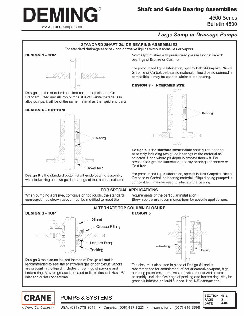
DESIGN 1 - TOP
Design 1 is the standard cast iron column top closure. On
Standard Fitted and All Iron pumps, it is of Fianite material. On
alloy pumps, it will be of the same material as the liquid end parts
DESIGN 6 - BOTTOM
Design 6 is the standard bottom shaft guide bearing assembly
with choker ring and two guide bearings of the material selected.
Normally furnished with pressurized grease lubrication with
bearings of Bronze or Cast Iron.
For pressurized liquid lubrication, specify Babbit-Graphite, Nickel
Graphite or Carbolube bearing material. If liquid being pumped is
compatible, it may be used to lubricate the bearing.
DESIGN 8 - INTERMEDIATE
Design 8 is the standard intermediate shaft guide bearing assembly including two guide bearings of the material as selected. Used where pit depth is greater than 6 ft. For pressurized grease lubrication, specify bearings of Bronze or Cast Iron.
For pressurized liquid lubrication, specify Babbit-Graphite, Nickel Graphite or Carbolube bearing material. If liquid being pumped is
compatible, it may be used to lubricate the bearing.
STANDARD SHAFT GUIDE BEARING ASSEMBLIESFor standard drainage service - non-corrosive liquids without abrasives or vapors.
FOR SPECIAL APPLICATIONS
When pumping abrasive, corrosive or hot liquids, the standard
construction as shown above must be modifi ed to meet the
requirements of the particular installation.
Shown below are recommendations for specifi c applications.
ALTERNATE TOP COLUMN CLOSURE
DESIGN 3 - TOP
Design 3 top closure is used instead of Design #1 and is
recommended to seal the shaft when gas or obnoxious vapors
are present in the liquid. Includes three rings of packing and
lantern ring. May be grease lubricated or liquid fl ushed. Has 1/8"
inlet and outlet connections.
DESIGN 5
Top closure is also used in place of Design #1 and is recommended for containment of hot or corrosive vapors, high pumping pressures, abrasives and with pressurized column assembly. Includes fi ve rings of packing and lantern ring. May be grease lubricated or liquid fl ushed. Has 1/8" connections.
www.cranepumps.com
SECTION
PAGE
DATE
USA: (937) 778-8947 • Canada: (905) 457-6223 • International: (937) 615-3598A Crane Co. Company
4
40-L
Large Sump or Drainage Pumps
4/08
Shaft and Guide Bearing Assemblies
4500 Series
Bulletin 4500
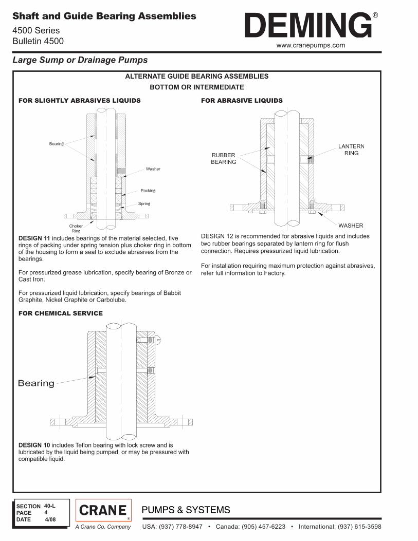
ALTERNATE GUIDE BEARING ASSEMBLIES
BOTTOM OR INTERMEDIATE
FOR SLIGHTLY ABRASIVES LIQUIDS
DESIGN 11 includes bearings of the material selected, fi ve rings of packing under spring tension plus choker ring in bottom of the housing to form a seal to exclude abrasives from the bearings.
For pressurized grease lubrication, specify bearing of Bronze or Cast Iron.
For pressurized liquid lubrication, specify bearings of Babbit Graphite, Nickel Graphite or Carbolube.
FOR CHEMICAL SERVICE
DESIGN 10 includes Tefl on bearing with lock screw and is lubricated by the liquid being pumped, or may be pressured with compatible liquid.
FOR ABRASIVE LIQUIDS
DESIGN 12 is recommended for abrasive liquids and includes
two rubber bearings separated by lantern ring for fl ush
connection. Requires pressurized liquid lubrication.
For installation requiring maximum protection against abrasives,
refer full information to Factory.

www.cranepumps.com
SECTION
PAGE
DATE
USA: (937) 778-8947 • Canada: (905) 457-6223 • International: (937) 615-3598A Crane Co. Company
5
40-L
Large Sump or Drainage Pumps
3/08
Pump Selection Data
4500 Series
Bulletin 4500
Total Pumping Head:
Often overlooked in selecting vertical pumps that take suction from open sumps is the need to add the losses in the sump below the mounting plate to the head above the mounting plate to determine the total pumping head for selecting the pump. These additions include the elevation from the lowest liquid in the sump to the support plate plus friction loss in the discharge elbow and discharge pipe plus velocity head in the discharge pipe to the support plate.
The pump characteristic curves indicate the pump performance measured at the casing discharge fl ange; therefore in selecting the pump size and motor horsepower, the total pumping head must include the data as above.
Example of Total Head Calculations:
Pump required - 400 GPM, Pit depth 10'-6", lowest liquid level 7ft. below support plate, highest point in discharge line 38ft., pressure required at the discharge 8 p.s.i., friction loss in 4" discharge line beyond the pump 4 ft.
Highest Elevation .........................................................38 ft.Pressure Required 8 p.s.i. x 2.31............................18.48 ft.Friction Loss - Discharge line.........................................4 ft.Lift in Sump ....................................................................7 ft.Friction in elbow and discharge pipe.........................2.05 ft.Velocity head in pump discharge pipe ......................1.58 ft.
Total Pumping Head ...................................................71.11 ft.
Normally the "pit depth" can be substituted to compensate for the low liquid level and pipe losses below the support plate; when added to the pumping head above the pump, this will give the approximate total pumping head for selecting the pump.
When the capacity and the total pumping head are specifi ed by the customer, it will be assumed that the total pumping head includes all friction losses and velocity head beyond the pump casing plus allowance for lowest liquid level in the sump; otherwise the indicated total pumping head must be corrected as above.
Minimum Submergence:
The distance from the surface of a liquid in a sump or tank to the pump suction inlet is known as submergence. Depending on the pump size, a "minimum submergence" is required to prevent vortex formation around the pump suction which will reduce pump capacity and may cause pump damage and rapid wear.
Submergence should not be confused with Net Positive Suc-tion Head or NPSH. It is possible to have suffi cient submer-gence but insuffi cient net positive head or vice versa depend-ing on the installation and liquid characteristics.
Proposed installations must be checked for both required sub-mergence and available NPSH to be sure they are equal to or greater than that required by the pump.
The table below shows minimum submergence above the pump suction nozzle in 65°F water, where pump is fi tted with standard strainer and where tank liquid velocity is negligible. Omission of pump strainer, liquid velocity, sump obstructions or other pumps installed in the same sump may require greater submergence.
Pump Selection Data
Minimum Submergence Above Suction Nozzle
Figure 4501 - 4511 - 4521
Pump Size 1 1½ 2½ 1¼ S 1½ S 1½ M 1½ L 2 S 2 M
Min. Subm. 18" 18" 18" 18" 18" 18" 18" 18" 18"
Pump Size 3 S 3 MD 4 S 4 MD 5 MSD 5 MD 6 MD 6 MLD
Min. Subm. 24" 24" 24" 24" 24" 24" 24" 24"
Figure 4565 - 4566 - 4568
Pump Size 4 x 4 x 12 6 x 4 x 12 6 x 6 x 12 8 x 6 x 12 8 x 8 x 12 10 x 10 x 12
Min. Subm. 8" 20" 24" 30" 36" 36"
www.cranepumps.com
SECTION
PAGE
DATE
USA: (937) 778-8947 • Canada: (905) 457-6223 • International: (937) 615-3598A Crane Co. Company
6
40-L
Large Sump or Drainage Pumps
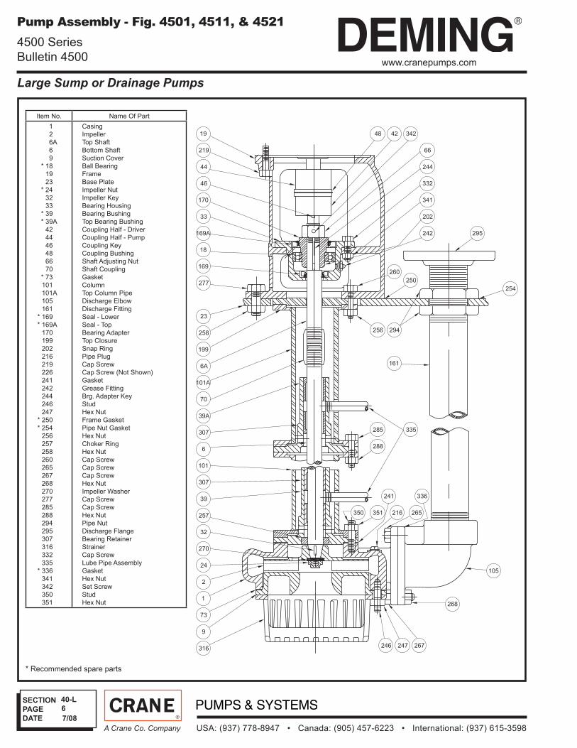
* Recommended spare parts
Item No. Name Of Part
1
2
6A
6
9
* 18
19
23
* 24
32
33
* 39
* 39A
42
44
46
48
66
70
* 73
101
101A
105
161
* 169
* 169A
170
199
202
216
219
226
241
242
244
246
247
* 250
* 254
256
257
258
260
265
267
268
270
277
285
288
294
295
307
316
332
335
* 336
341
342
350
351
Casing
Impeller
Top Shaft
Bottom Shaft
Suction Cover
Ball Bearing
Frame
Base Plate
Impeller Nut
Impeller Key
Bearing Housing
Bearing Bushing
Top Bearing Bushing
Coupling Half - Driver
Coupling Half - Pump
Coupling Key
Coupling Bushing
Shaft Adjusting Nut
Shaft Coupling
Gasket
Column
Top Column Pipe
Discharge Elbow
Discharge Fitting
Seal - Lower
Seal - Top
Bearing Adapter
Top Closure
Snap Ring
Pipe Plug
Cap Screw
Cap Screw (Not Shown)
Gasket
Grease Fitting
Brg. Adapter Key
Stud
Hex Nut
Frame Gasket
Pipe Nut Gasket
Hex Nut
Choker Ring
Hex Nut
Cap Screw
Cap Screw
Cap Screw
Hex Nut
Impeller Washer
Cap Screw
Cap Screw
Hex Nut
Pipe Nut
Discharge Flange
Bearing Retainer
Strainer
Cap Screw
Lube Pipe Assembly
Gasket
Hex Nut
Set Screw
Stud
Hex Nut
7/08
Pump Assembly - Fig. 4501, 4511, & 4521
4500 Series
Bulletin 4500
SECTION
PAGE
DATE
USA: (937) 778-8947 • Canada: (905) 457-6223 • International: (937) 615-3598A Crane Co. Company
Large Sump or Drainage Pumps
7
40-L
www.cranepumps.com
Customer Shop Order No. Date: By:
Pump
Data
Fig. No. Size Curve No. GPM Head Sp. Gr. Temp. Rotation Packing/Seal
Motor
Data
MFGR Hp RPM Phase-Cycle Voltage Frame Enclosure Insulation Furnished
by
Mounted
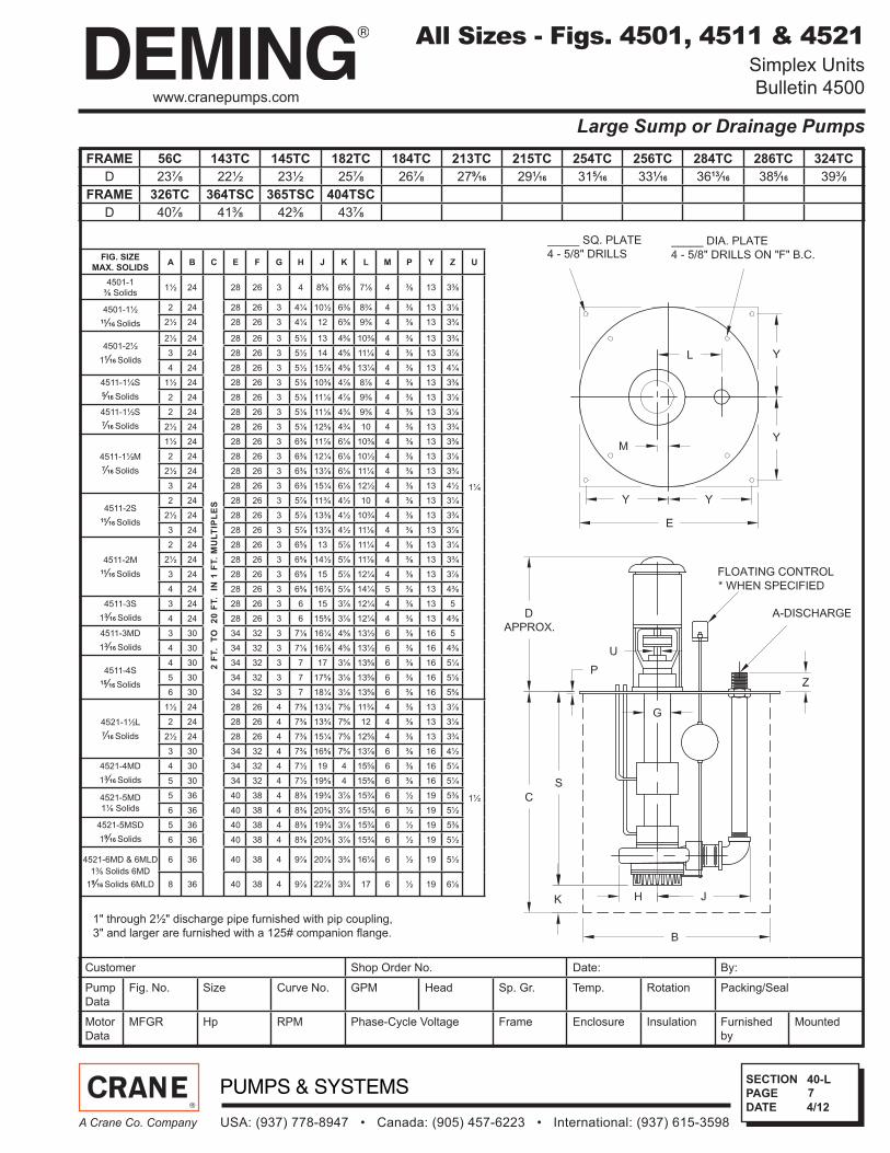
All Sizes - Figs. 4501, 4511 & 4521 Simplex Units
Bulletin 4500
FRAME 56C 143TC 145TC 182TC 184TC 213TC 215TC 254TC 256TC 284TC 286TC 324TC
D 23⅞ 22½ 23½ 25⅞ 26⅞ 279⁄16 291⁄16 315⁄16 331⁄16 3613⁄16 385⁄16 39⅜
FRAME 326TC 364TSC 365TSC 404TSC
D 40⅞ 41⅜ 42⅜ 43⅞
FIG. SIZE
MAX. SOLIDSA B C E F G H J K L M P Y Z U
4501-1
⅜ Solids1½ 24
2 F
T.
TO
2
0 F
T.
IN
1 F
T.
MU
LT
IPL
ES
28 26 3 4 8⅝ 6⅝ 7⅛ 4 ⅜ 13 3⅜
1¼
4501-1½
11⁄16 Solids
2 24 28 26 3 4¼ 10½ 6⅜ 8¾ 4 ⅜ 13 3⅛
2½ 24 28 26 3 4¼ 12 6⅜ 9⅜ 4 ⅜ 13 3¾
4501-2½
11⁄16 Solids
2½ 24 28 26 3 5½ 13 4⅝ 10⅜ 4 ⅜ 13 3¾
3 24 28 26 3 5½ 14 4⅝ 11¼ 4 ⅜ 13 3⅞
4 24 28 26 3 5½ 15⅞ 4⅝ 13¼ 4 ⅜ 13 4¼
4511-1¼S
5⁄16 Solids
1½ 24 28 26 3 5⅛ 10⅜ 4⅞ 8⅞ 4 ⅜ 13 3⅜
2 24 28 26 3 5⅛ 11⅛ 4⅞ 9⅜ 4 ⅜ 13 3⅛
4511-1½S
7⁄16 Solids
2 24 28 26 3 5⅛ 11⅛ 4¾ 9⅜ 4 ⅜ 13 3⅛
2½ 24 28 26 3 5⅛ 12⅝ 4¾ 10 4 ⅜ 13 3¾
4511-1½M
7⁄16 Solids
1½ 24 28 26 3 6⅜ 11⅞ 6⅛ 10⅜ 4 ⅜ 13 3⅜
2 24 28 26 3 6⅜ 12¼ 6⅛ 10½ 4 ⅜ 13 3⅛
2½ 24 28 26 3 6⅜ 13⅞ 6⅛ 11¼ 4 ⅜ 13 3¾
3 24 28 26 3 6⅜ 15¼ 6⅛ 12½ 4 ⅜ 13 4½
4511-2S
11⁄16 Solids
2 24 28 26 3 5⅞ 11¾ 4½ 10 4 ⅜ 13 3¼
2½ 24 28 26 3 5⅞ 13⅜ 4½ 10¾ 4 ⅜ 13 3¾
3 24 28 26 3 5⅞ 13⅞ 4½ 11⅛ 4 ⅜ 13 3⅞
4511-2M
11⁄16 Solids
2 24 28 26 3 6⅝ 13 5⅞ 11¼ 4 ⅜ 13 3¼
2½ 24 28 26 3 6⅝ 14½ 5⅞ 11⅞ 4 ⅜ 13 3¾
3 24 28 26 3 6⅝ 15 5⅞ 12¼ 4 ⅜ 13 3⅞
4 24 28 26 3 6⅝ 16⅞ 5⅞ 14¼ 5 ⅜ 13 4⅜
4511-3S
13⁄16 Solids
3 24 28 26 3 6 15 3⅞ 12¼ 4 ⅜ 13 5
4 24 28 26 3 6 15⅝ 3⅞ 12¼ 4 ⅜ 13 4⅜
4511-3MD
13⁄16 Solids
3 30 34 32 3 7⅛ 16¼ 4⅝ 13½ 6 ⅜ 16 5
4 30 34 32 3 7⅛ 16⅞ 4⅝ 13½ 6 ⅜ 16 4⅜
4511-4S
15⁄16 Solids
4 30 34 32 3 7 17 3⅛ 13⅝ 6 ⅜ 16 5¼
5 30 34 32 3 7 17⅝ 3⅛ 13⅝ 6 ⅜ 16 5⅛
6 30 34 32 3 7 18¼ 3⅛ 13⅝ 6 ⅜ 16 5⅝
4521-1½L
7⁄16 Solids
1½ 24 28 26 4 7⅜ 13¼ 7⅝ 11¾ 4 ⅜ 13 3⅞
1½
2 24 28 26 4 7⅜ 13¾ 7⅝ 12 4 ⅜ 13 3⅛
2½ 24 28 26 4 7⅜ 15¼ 7⅝ 12⅝ 4 ⅜ 13 3¾
3 30 34 32 4 7⅜ 16⅝ 7⅝ 13⅞ 6 ⅜ 16 4½
4521-4MD
13⁄16 Solids
4 30 34 32 4 7½ 19 4 15⅝ 6 ⅜ 16 5¼
5 30 34 32 4 7½ 19⅝ 4 15⅝ 6 ⅜ 16 5¼
4521-5MD
1⅛ Solids
5 36 40 38 4 8⅜ 19¾ 3⅞ 15¾ 6 ½ 19 5⅜
6 36 40 38 4 8⅜ 20⅜ 3⅞ 15¾ 6 ½ 19 5½
4521-5MSD
19⁄16 Solids
5 36 40 38 4 8⅜ 19¾ 3⅞ 15¾ 6 ½ 19 5⅜
6 36 40 38 4 8⅜ 20⅜ 3⅞ 15¾ 6 ½ 19 5½
4521-6MD & 6MLD
1⅜ Solids 6MD
19⁄16 Solids 6MLD
6 36 40 38 4 9⅞ 20⅞ 3¾ 16¼ 6 ½ 19 5½
8 36 40 38 4 9⅞ 22⅞ 3¾ 17 6 ½ 19 6⅛
1" through 2½" discharge pipe furnished with pip coupling,
3" and larger are furnished with a 125# companion fl ange.
4/12
SECTION
PAGE
DATE
Large Sump or Drainage Pumps
USA: (937) 778-8947 • Canada: (905) 457-6223 • International: (937) 615-3598A Crane Co. Company
8
40-L
www.cranepumps.com
Customer Shop Order No. Date: By:
Pump
Data
Fig. No. Size Curve No. GPM Head Sp. Gr. Temp. Rotation Packing/Seal
Motor
Data
MFGR Hp RPM Phase-Cycle Voltage Frame Enclosure Insulation Furnished
by
Mounted
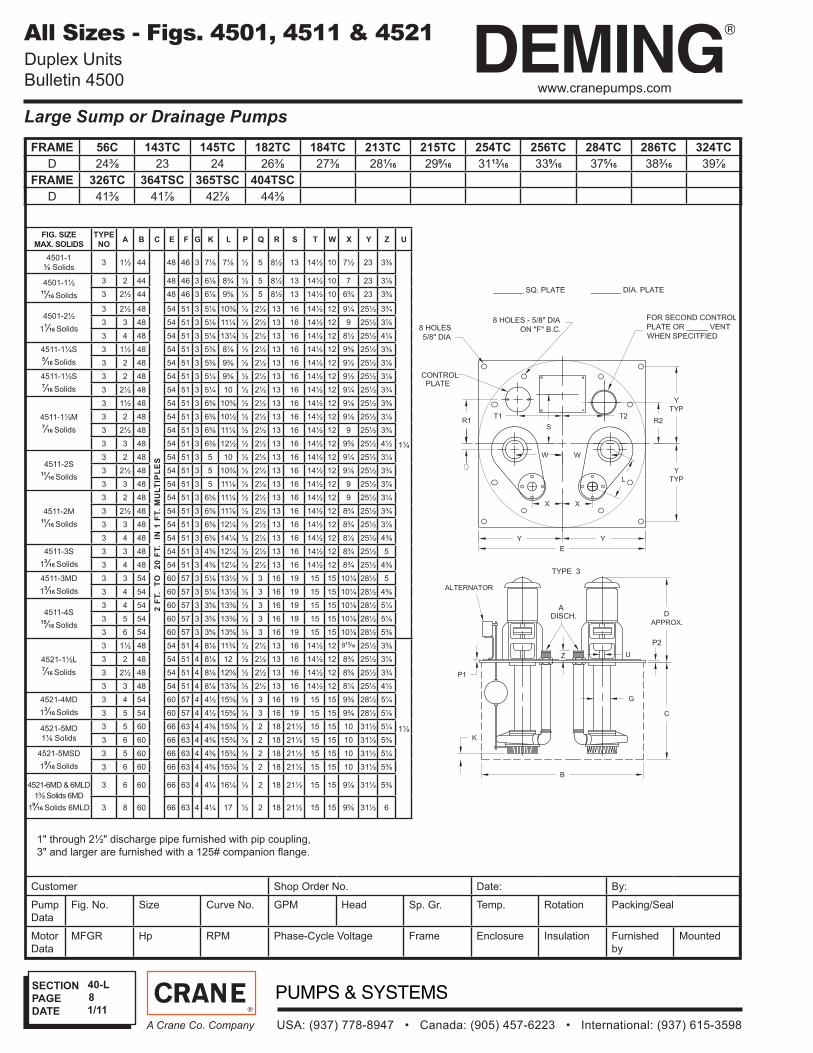
FRAME 56C 143TC 145TC 182TC 184TC 213TC 215TC 254TC 256TC 284TC 286TC 324TC
D 24⅜ 23 24 26⅜ 27⅜ 281⁄16 299⁄16 3113⁄16 339⁄16 375⁄16 383⁄16 39⅞
FRAME 326TC 364TSC 365TSC 404TSC
D 41⅜ 41⅞ 42⅞ 44⅜
FIG. SIZE
MAX. SOLIDS
TYPE
NOA B C E F G K L P Q R S T W X Y Z U
4501-1
⅜ Solids3 1½ 44
2 F
T.
TO
2
0 F
T.
IN
1 F
T.
MU
LT
IPL
ES
48 46 3 7⅛ 7⅛ ½ 5 8½ 13 14½ 10 7½ 23 3⅜
1¼
4501-1½11⁄16 Solids
3 2 44 48 46 3 6⅞ 8¾ ½ 5 8½ 13 14½ 10 7 23 3⅛
3 2½ 44 48 46 3 6⅞ 9⅜ ½ 5 8½ 13 14½ 10 6¾ 23 3¾
4501-2½
11⁄16 Solids
3 2½ 48 54 51 3 5⅛ 10⅜ ½ 2½ 13 16 14½ 12 9¼ 25½ 3¾
3 3 48 54 51 3 5⅛ 11¼ ½ 2½ 13 16 14½ 12 9 25½ 3⅞
3 4 48 54 51 3 5⅛ 13¼ ½ 2½ 13 16 14½ 12 8½ 25½ 4¼
4511-1¼S5⁄16 Solids
3 1½ 48 54 51 3 5⅜ 8⅞ ½ 2½ 13 16 14½ 12 9⅝ 25½ 3⅜
3 2 48 54 51 3 5⅜ 9⅜ ½ 2½ 13 16 14½ 12 9½ 25½ 3⅛
4511-1½S7⁄16 Solids
3 2 48 54 51 3 5¼ 9⅜ ½ 2½ 13 16 14½ 12 9½ 25½ 3⅛
3 2½ 48 54 51 3 5¼ 10 ½ 2½ 13 16 14½ 12 9¼ 25½ 3¾
4511-1½M7⁄16 Solids
3 1½ 48 54 51 3 6⅜ 10⅜ ½ 2½ 13 16 14½ 12 9⅛ 25½ 3⅜
3 2 48 54 51 3 6⅜ 10½ ½ 2½ 13 16 14½ 12 9⅛ 25½ 3⅛
3 2½ 48 54 51 3 6⅜ 11¼ ½ 2½ 13 16 14½ 12 9 25½ 3¾
3 3 48 54 51 3 6⅜ 12½ ½ 2½ 13 16 14½ 12 9⅝ 25½ 4½
4511-2S11⁄16 Solids
3 2 48 54 51 3 5 10 ½ 2½ 13 16 14½ 12 9¼ 25½ 3¼
3 2½ 48 54 51 3 5 10¾ ½ 2½ 13 16 14½ 12 9⅛ 25½ 3¾
3 3 48 54 51 3 5 11⅛ ½ 2½ 13 16 14½ 12 9 25½ 3⅞
4511-2M11⁄16 Solids
3 2 48 54 51 3 6⅜ 11¼ ½ 2½ 13 16 14½ 12 9 25½ 3¼
3 2½ 48 54 51 3 6⅜ 11⅞ ½ 2½ 13 16 14½ 12 8¾ 25½ 3¾
3 3 48 54 51 3 6⅜ 12¼ ½ 2½ 13 16 14½ 12 8¾ 25½ 3⅞
3 4 48 54 51 3 6⅜ 14¼ ½ 2½ 13 16 14½ 12 8½ 25½ 4⅜
4511-3S
13⁄16 Solids
3 3 48 54 51 3 4⅜ 12¼ ½ 2½ 13 16 14½ 12 8¾ 25½ 5
3 4 48 54 51 3 4⅜ 12¼ ½ 2½ 13 16 14½ 12 8¾ 25½ 4⅜
4511-3MD
13⁄16 Solids
3 3 54 60 57 3 5⅛ 13½ ½ 3 16 19 15 15 10¼ 28½ 5
3 4 54 60 57 3 5⅛ 13½ ½ 3 16 19 15 15 10¼ 28½ 4⅜
4511-4S15⁄16 Solids
3 4 54 60 57 3 3⅝ 13⅜ ½ 3 16 19 15 15 10⅛ 28½ 5¼
3 5 54 60 57 3 3⅝ 13⅜ ½ 3 16 19 15 15 10⅛ 28½ 5⅛
3 6 54 60 57 3 3⅝ 13⅝ ½ 3 16 19 15 15 10⅛ 28½ 5⅜
4521-1½L7⁄16 Solids
3 1½ 48 54 51 4 8⅛ 11¾ ½ 2½ 13 16 14½ 12 813⁄16 25½ 3⅜
1½
3 2 48 54 51 4 8⅛ 12 ½ 2½ 13 16 14½ 12 8¾ 25½ 3⅛
3 2½ 48 54 51 4 8⅛ 12⅝ ½ 2½ 13 16 14½ 12 8⅝ 25½ 3¾
3 3 48 54 51 4 8⅛ 13⅞ ½ 2½ 13 16 14½ 12 8¼ 25½ 4½
4521-4MD
13⁄16 Solids
3 4 54 60 57 4 4½ 15⅝ ½ 3 16 19 15 15 9⅜ 28½ 5¼
3 5 54 60 57 4 4½ 15⅝ ½ 3 16 19 15 15 9⅜ 28½ 5⅛
4521-5MD
1⅛ Solids
3 5 60 66 63 4 4⅜ 15¾ ½ 2 18 21½ 15 15 10 31½ 5¼
3 6 60 66 63 4 4⅜ 15¾ ½ 2 18 21½ 15 15 10 31½ 5⅜
4521-5MSD
19⁄16 Solids
3 5 60 66 63 4 4⅜ 15¾ ½ 2 18 21½ 15 15 10 31½ 5¼
3 6 60 66 63 4 4⅜ 15¾ ½ 2 18 21½ 15 15 10 31½ 5⅜
4521-6MD & 6MLD
1⅜ Solids 6MD
19⁄16 Solids 6MLD
3 6 60 66 63 4 4¼ 16¼ ½ 2 18 21½ 15 15 9⅞ 31½ 5⅜
3 8 60 66 63 4 4¼ 17 ½ 2 18 21½ 15 15 9⅝ 31½ 6
1" through 2½" discharge pipe furnished with pip coupling,
3" and larger are furnished with a 125# companion fl ange.
All Sizes - Figs. 4501, 4511 & 4521 Duplex Units
Bulletin 4500
1/11
SECTION
PAGE
DATE
USA: (937) 778-8947 • Canada: (905) 457-6223 • International: (937) 615-3598A Crane Co. Company
Large Sump or Drainage Pumps
9
40-L
www.cranepumps.com
Customer Shop Order No. Date: By:
Pump
Data
Fig. No. Size Curve No. GPM Head Sp. Gr. Temp. Rotation Packing/Seal
Motor
Data
MFGR Hp RPM Phase-Cycle Voltage Frame Enclosure Insulation Furnished
by
Mounted
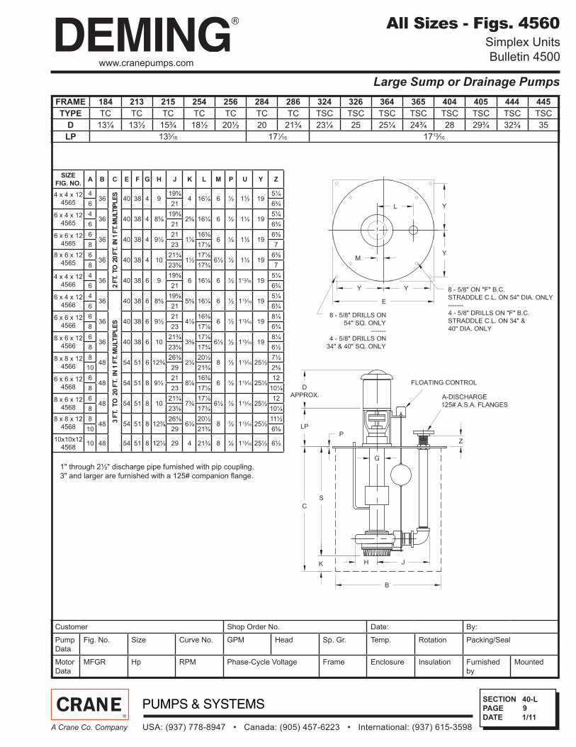
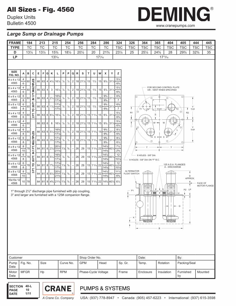
All Sizes - Figs. 4560Simplex Units
Bulletin 4500
FRAME 184 213 215 254 256 284 286 324 326 364 365 404 405 444 445
TYPE TC TC TC TC TC TC TC TSC TSC TSC TSC TSC TSC TSC TSC
D 13¼ 13½ 15¾ 18½ 20½ 20 21¾ 23¼ 25 25¼ 24¾ 28 29¾ 32¾ 35
LP 135⁄16 171⁄16 1713⁄16
SIZE
FIG. NO.A B C E F G H J K L M P U Y Z
4 x 4 x 12
4565
436
2 F
T.
TO
20 F
T.
IN 1
FT. M
ULTIP
LE
S
40 38 4 919⅝
4 16¼ 6 ½ 1½ 195¼
6 21 6¾
6 x 4 x 12
4565
436 40 38 4 8⅝
19⅝2⅝ 16¼ 6 ½ 1½ 19
5¼
6 21 6¾
6 x 6 x 12
4565
636 40 38 4 9½
211⅞
16⅜6 ½ 1½ 19
6⅜
8 23 17⅛ 7
8 x 6 x 12
4565
636 40 38 4 10
21¾1½
17⅛6½ ½ 1½ 19
6⅜
8 23⅝ 17¾ 7
4 x 4 x 12
4566
436 40 38 6 9
19⅝6 16¼ 6 ½ 113⁄16 19
5¼
6 21 6¾
6 x 4 x 12
4566
436
3 F
T. T
O 20 F
T. IN
1 F
T. M
ULT
IPL
ES
40 38 6 8⅝19⅝
5⅝ 16¼ 6 ½ 113⁄16 195¼
6 21 6¾
6 x 6 x 12
4566
636 40 38 6 9½
214⅞
16⅜6 ½ 113⁄16 19
8¼
8 23 17⅛ 6¾
8 x 6 x 12
4566
636 40 38 6 10
21¾3⅜
17⅛6½ ½ 113⁄16 19
8¼
8 23⅝ 17¾ 6½
8 x 8 x 12
4566
848 54 51 6 12⅜
26⅜2¼
20½8 ½ 113⁄16 25½
7½
10 29 21¾ 2⅝
6 x 6 x 12
4568
648 54 51 8 9½
218⅞
16⅜6 ½ 113⁄16 25½
12
8 23 17⅛ 10¼
8 x 6 x 12
4568
648 54 51 8 10
21¾7⅜
17⅛6½ ½ 113⁄16 25½
12
8 23⅝ 17¾ 10¼
8 x 8 x 12
4568
848 54 51 8 12⅜
26⅜6¼
20½8 ½ 113⁄16 25½
11½
10 29 21¾ 6⅝
10x10x12
456810 48 54 51 8 12½ 29 4 21¾ 8 ½ 113⁄16 25½ 6½
1" through 2½" discharge pipe furnished with pip coupling,
3" and larger are furnished with a 125# companion fl ange.
1/11
SECTION
PAGE
DATE
Large Sump or Drainage Pumps
USA: (937) 778-8947 • Canada: (905) 457-6223 • International: (937) 615-3598A Crane Co. Company
10
40-L
www.cranepumps.com
Customer Shop Order No. Date: By:
Pump
Data
Fig. No. Size Curve No. GPM Head Sp. Gr. Temp. Rotation Packing/Seal
Motor
Data
MFGR Hp RPM Phase-Cycle Voltage Frame Enclosure Insulation Furnished
by
Mounted
All Sizes - Fig. 4560 Duplex Units
Bulletin 4500
SIZE
FIG. NO.A B C E F G K L P P Q R S T U W X Y Z
4 x 4 x 12
4565
460
2 F
T.
TO
20 F
T.
IN 1
FT. M
ULTIP
LE
S
66 63 4 4¼ 16¼ ⅞ ½ 2 18 21¼ 15 1½ 15 9⅞ 31½5¼
6 6¾
6 x 4 x 12
4565
460 66 63 4 3 16¼ ⅞ ½ 2 18 21½ 15 1½ 15 9⅞ 31½
5¼
6 6¾
6 x 6 x 12
4565
660 66 63 4 2¼
16⅜⅞ ½ 2 18 21½ 15 1½ 15
9¾31½
6⅜
8 17⅛ 9⅝ 7
8 x 6 x 12
4565
660 66 63 4 1⅞
17⅛⅞ ½ 2 18 21½ 15 1½ 15
9⅝31½
6⅜
8 17¾ 9⅜ 7
4 x 4 x 12
4566
460 66 63 6 6¼ 16¼ ⅞ ½ 2 18 21½ 15 113⁄16 15 9⅞ 31½
5¼
6 6¾
6 x 4 x 12
4566
460
3 F
T. T
O 20 F
T. IN
1 F
T. M
ULT
IPL
ES
66 63 6 6 16¼ ⅞ ½ 2 18 21½ 15 113⁄16 15 9⅞ 31½5¼
6 6¾
6 x 6 x 12
4566
660 66 63 6 5¼
16⅜⅞ ½ 2 18 21½ 15 113⁄16 15
9¾31½
8¼
8 17⅛ 9⅝ 6¾
8 x 6 x 12
4566
660 66 63 6 3¾
17⅛⅞ ½ 2 18 21½ 15 113⁄16 15
9⅝31½
8¼
8 17¾ 9⅜ 6½
8 x 8 x 12
4566
878 84 81 6 2⅞
20½1⅛ ⅝ -- 26 29 15 113⁄16 22
14⅞40½
7½
10 21¾ 14⅜ 2⅝
6 x 6 x 12
4568
678 84 81 8 5¼
16⅜⅞ ⅝ -- 26 29 15 113⁄16 22
14⅞40½
12
8 17⅛ 14⅜ 10¼
8 x 6 x 12
4568
678 84 81 8 7¾
17⅛1⅛ ⅝ -- 26 29 15 113⁄16 22
14⅞40½
12
8 17¾ 14⅜ 10¼
8 x 8 x 12
4568
878 84 81 8 6⅞
20½1⅛ ⅝ -- 26 29 15 113⁄16 22
14⅞40½
11½
10 21¾ 14⅜ 6⅝
10x10x 12
456810 78 84 81 8 4⅝ 21¾ 1⅛ ⅝ -- 26 29 15 113⁄16 22 14⅜ 40½ 6½
1" through 2½" discharge pipe furnished with pip coupling,
3" and larger are furnished with a 125# companion fl ange.
FRAME 184 213 215 254 256 284 286 324 326 364 365 404 405 444 445
TYPE TC TC TC TC TC TC TC TSC TSC TSC TSC TSC TSC TSC TSC
D 13¼ 13½ 15¾ 18½ 20½ 20 21¾ 23¼ 25 25¼ 24¾ 28 29¾ 32¾ 35
LP 135⁄16 171⁄16 1713⁄16
1/11
SECTION
PAGE
DATE
USA: (937) 778-8947 • Canada: (905) 457-6223 • International: (937) 615-3598A Crane Co. Company
11
40-L
www.cranepumps.com
Large Sump or Drainage Pumps
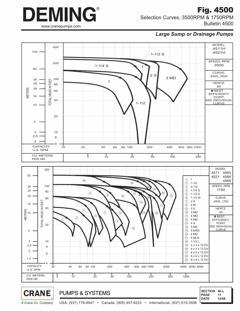
Fig. 4500Selection Curves, 3500RPM & 1750RPM
Bulletin 4500
12/08
SECTION
PAGE
DATE
USA: (937) 778-8947 • Canada: (905) 457-6223 • International: (937) 615-3598A Crane Co. Company
12
40-L
www.cranepumps.com
Large Sump or Drainage Pumps
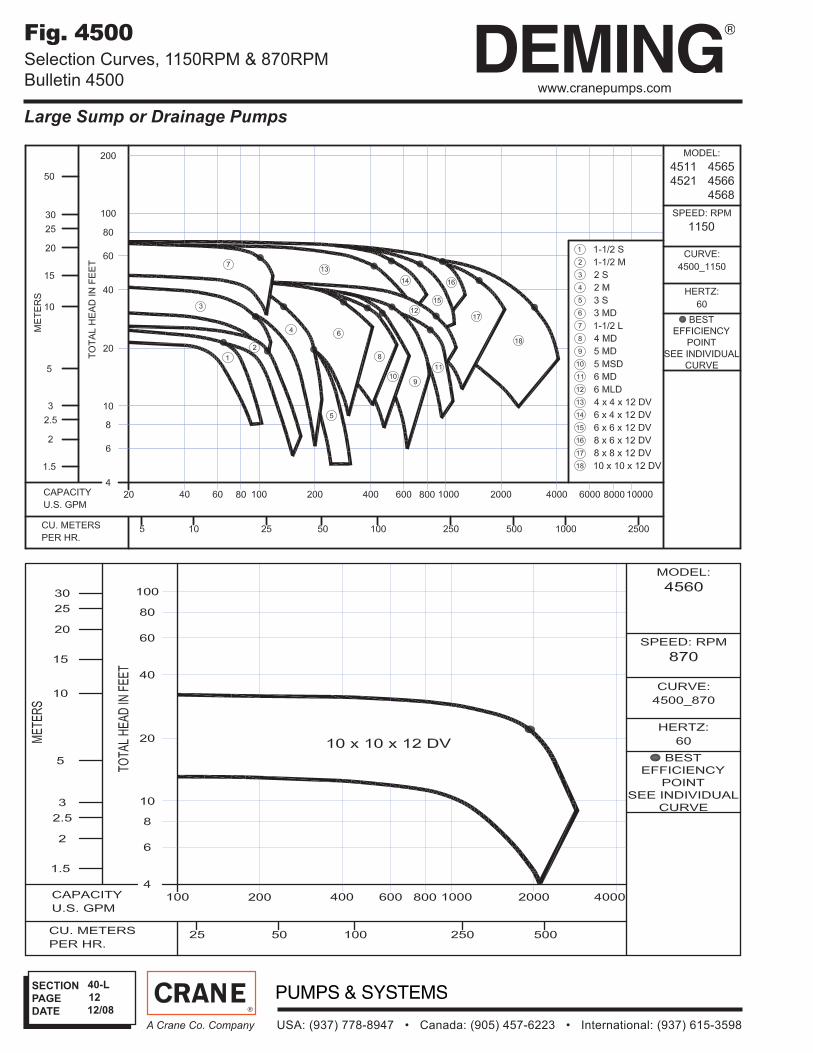
Fig. 4500Selection Curves, 1150RPM & 870RPM
Bulletin 4500
12/08
SECTION
PAGE
DATE
USA: (937) 778-8947 • Canada: (905) 457-6223 • International: (937) 615-3598A Crane Co. Company
13
40-L
www.cranepumps.com
Large Sump or Drainage Pumps
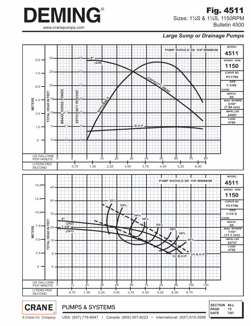
Fig. 4511Sizes: 1¼S & 1½S, 1150RPM
Bulletin 4500
7/07
SECTION
PAGE
DATE
USA: (937) 778-8947 • Canada: (905) 457-6223 • International: (937) 615-3598A Crane Co. Company
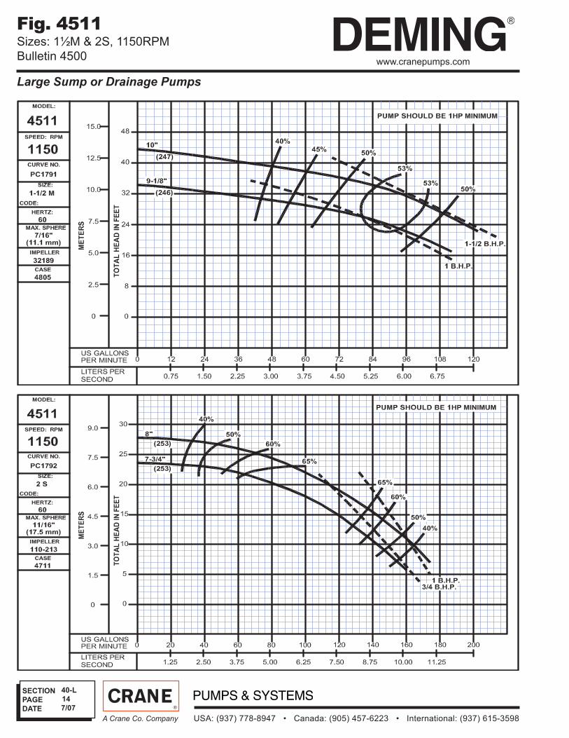
14
40-L
www.cranepumps.com
Large Sump or Drainage Pumps
Fig. 4511Sizes: 1½M & 2S, 1150RPM
Bulletin 4500
7/07

SECTION
PAGE
DATE
USA: (937) 778-8947 • Canada: (905) 457-6223 • International: (937) 615-3598A Crane Co. Company
15
40-L
www.cranepumps.com
Large Sump or Drainage Pumps
Fig. 4511Sizes: 2M & 3S, 1150RPM
Bulletin 4500
7/07

SECTION
PAGE
DATE
USA: (937) 778-8947 • Canada: (905) 457-6223 • International: (937) 615-3598A Crane Co. Company
16
40-L
www.cranepumps.com
Large Sump or Drainage Pumps
Fig. 4511 & 4521Sizes: 3MD & 1½L, 1150RPM
Bulletin 4500
7/07
SECTION
PAGE
DATE
USA: (937) 778-8947 • Canada: (905) 457-6223 • International: (937) 615-3598A Crane Co. Company
17
40-L
www.cranepumps.com
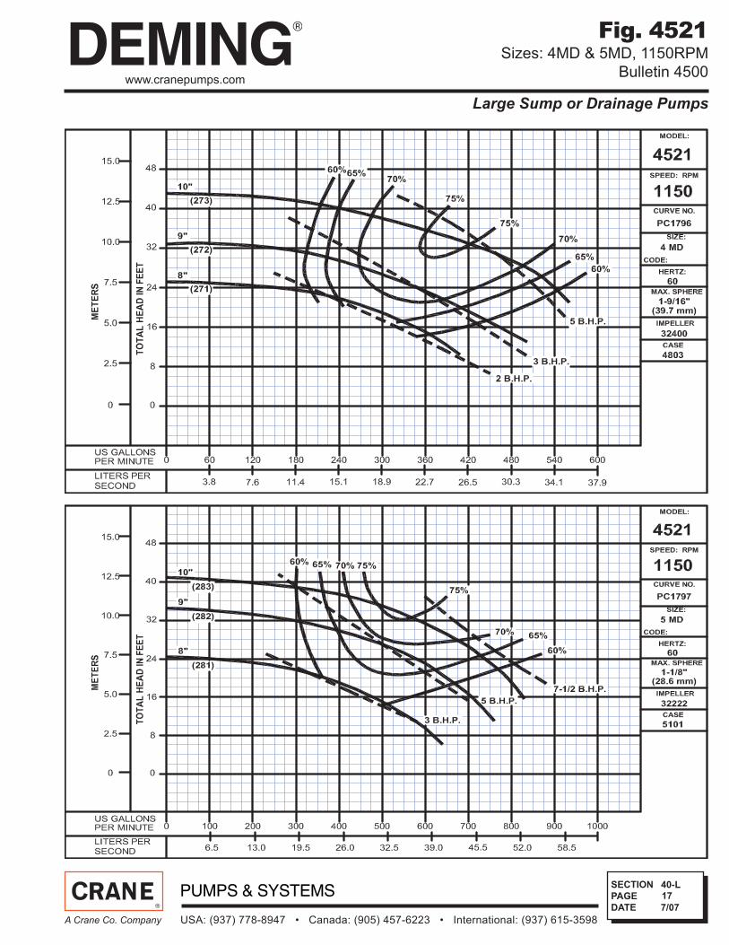
Large Sump or Drainage Pumps
Fig. 4521Sizes: 4MD & 5MD, 1150RPM
Bulletin 4500
7/07

SECTION
PAGE
DATE
USA: (937) 778-8947 • Canada: (905) 457-6223 • International: (937) 615-3598A Crane Co. Company
18
40-L
www.cranepumps.com
Large Sump or Drainage Pumps
Fig. 4521Sizes: 5 MSD & 6MD, 1150RPM
Bulletin 4500
7/07
SECTION
PAGE
DATE
USA: (937) 778-8947 • Canada: (905) 457-6223 • International: (937) 615-3598A Crane Co. Company
19
40-L
www.cranepumps.com
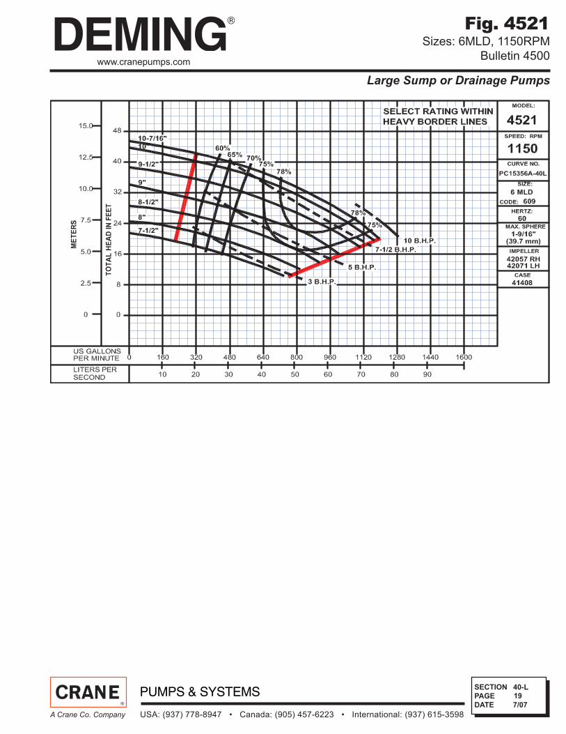
Large Sump or Drainage Pumps
Fig. 4521Sizes: 6MLD, 1150RPM
Bulletin 4500
7/07

SECTION
PAGE
DATE
USA: (937) 778-8947 • Canada: (905) 457-6223 • International: (937) 615-3598A Crane Co. Company
20
40-L
www.cranepumps.com
Large Sump or Drainage Pumps
Fig. 4565, 4566 & 4568Sizes: 4 x 4 x 12 DV & 6 x 4 x 12 DV, 1150RPM
Bulletin 4500
7/07

SECTION
PAGE
DATE
USA: (937) 778-8947 • Canada: (905) 457-6223 • International: (937) 615-3598A Crane Co. Company
21
40-L
www.cranepumps.com
Large Sump or Drainage Pumps
Fig. 4565, 4566 & 4568Sizes: 6 x 6 x 12 DV & 8 x 6 x 12 DV, 1150RPM
Bulletin 4500
7/07
SECTION
PAGE
DATE
USA: (937) 778-8947 • Canada: (905) 457-6223 • International: (937) 615-3598A Crane Co. Company
22
40-L
www.cranepumps.com
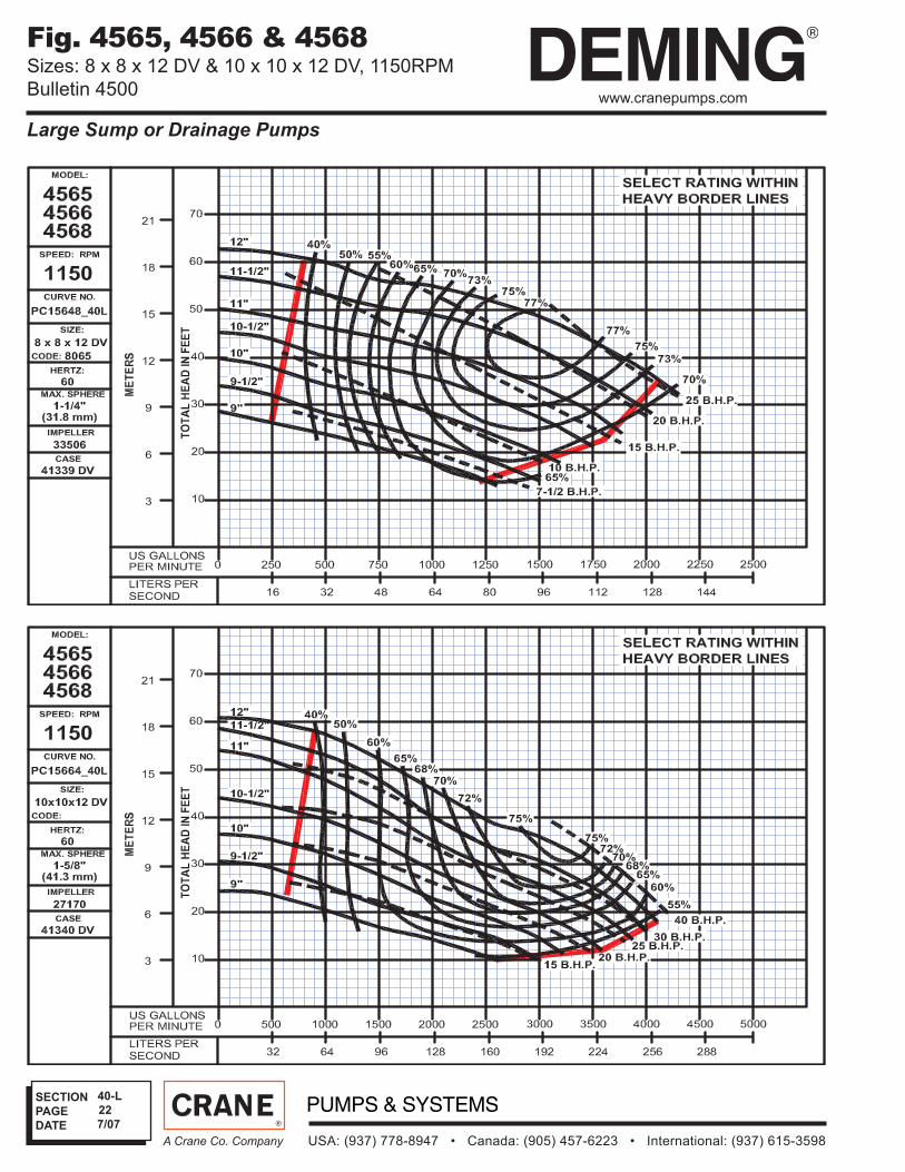
Large Sump or Drainage Pumps
Fig. 4565, 4566 & 4568Sizes: 8 x 8 x 12 DV & 10 x 10 x 12 DV, 1150RPM
Bulletin 4500
7/07

SECTION
PAGE
DATE
USA: (937) 778-8947 • Canada: (905) 457-6223 • International: (937) 615-3598A Crane Co. Company
23
40-L
www.cranepumps.com
Large Sump or Drainage Pumps
Fig. 4565, 4566 & 4568Size: 10 x 10 x 12 DV, 870RPM
Bulletin 4500
7/07
SECTION
PAGE
DATE
USA: (937) 778-8947 • Canada: (905) 457-6223 • International: (937) 615-3598A Crane Co. Company
24
40-L
www.cranepumps.com
Large Sump or Drainage Pumps
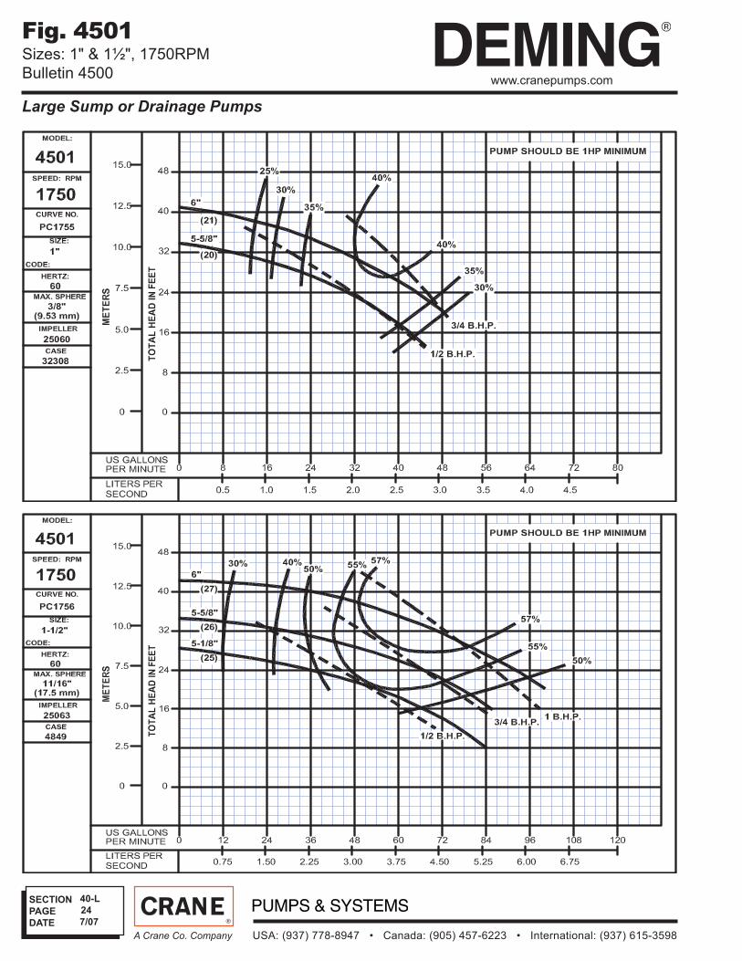
Fig. 4501Sizes: 1" & 1½", 1750RPM
Bulletin 4500
7/07
SECTION
PAGE
DATE
USA: (937) 778-8947 • Canada: (905) 457-6223 • International: (937) 615-3598A Crane Co. Company
25
40-L
www.cranepumps.com
Large Sump or Drainage Pumps
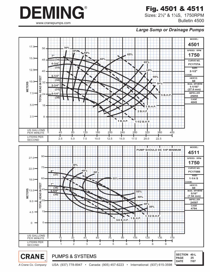
Fig. 4501 & 4511Sizes: 2½" & 1¼S, 1750RPM
Bulletin 4500
7/07
SECTION
PAGE
DATE
USA: (937) 778-8947 • Canada: (905) 457-6223 • International: (937) 615-3598A Crane Co. Company
26
40-L
www.cranepumps.com
Large Sump or Drainage Pumps
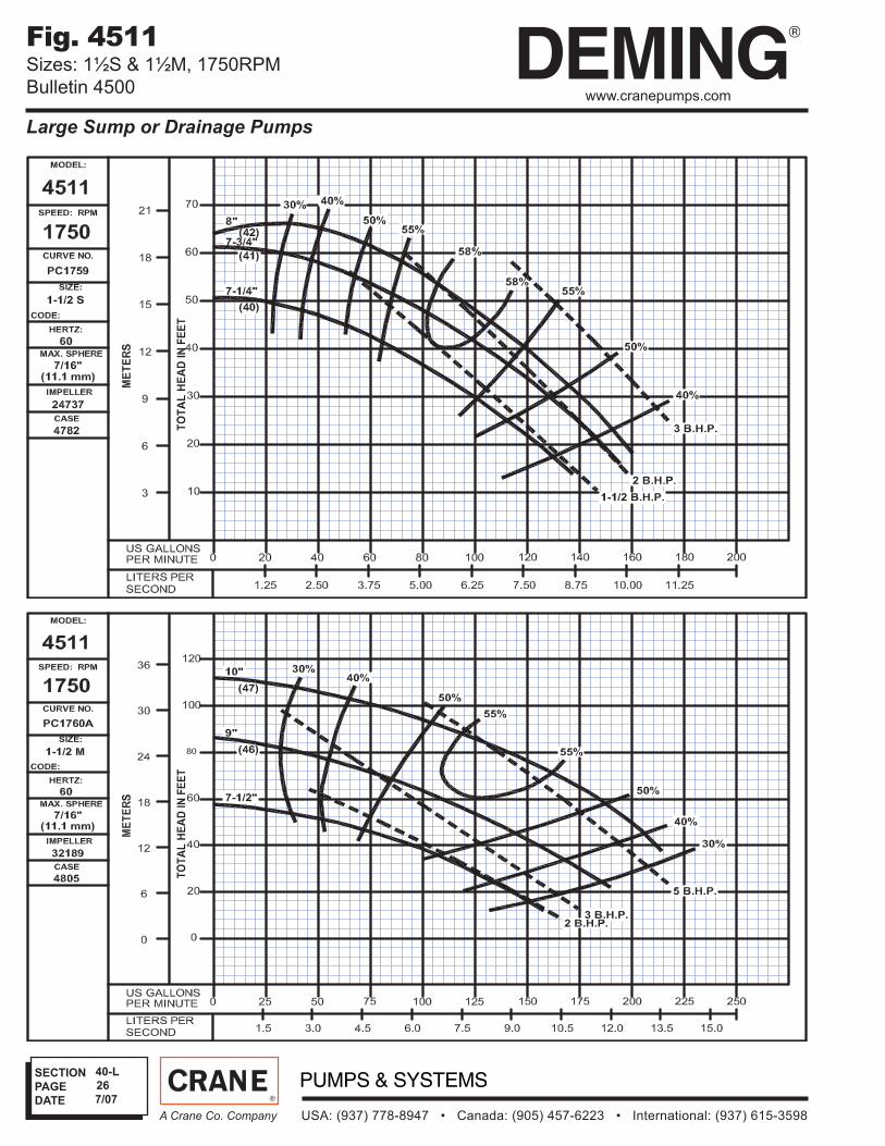
Fig. 4511Sizes: 1½S & 1½M, 1750RPM
Bulletin 4500
7/07
SECTION
PAGE
DATE
USA: (937) 778-8947 • Canada: (905) 457-6223 • International: (937) 615-3598A Crane Co. Company
27
40-L
www.cranepumps.com
Large Sump or Drainage Pumps
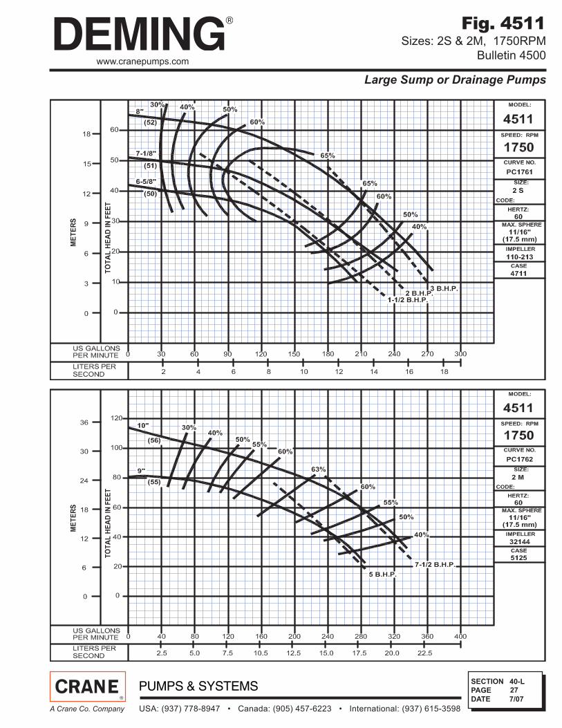
Fig. 4511Sizes: 2S & 2M, 1750RPM
Bulletin 4500
7/07

SECTION
PAGE
DATE
USA: (937) 778-8947 • Canada: (905) 457-6223 • International: (937) 615-3598A Crane Co. Company
28
40-L
www.cranepumps.com
Large Sump or Drainage Pumps
Fig. 4511Sizes: 3S & 3MD, 1750RPM
Bulletin 4500
7/07

SECTION
PAGE
DATE
USA: (937) 778-8947 • Canada: (905) 457-6223 • International: (937) 615-3598A Crane Co. Company
29
40-L
www.cranepumps.com
Large Sump or Drainage Pumps
Fig. 4521Sizes: 4 MD & 5 MD, 1750RPM
Bulletin 4500
7/07

SECTION
PAGE
DATE
USA: (937) 778-8947 • Canada: (905) 457-6223 • International: (937) 615-3598A Crane Co. Company
30
40-L
www.cranepumps.com
Large Sump or Drainage Pumps
Fig. 4511 & 4521Sizes: 4 S & 5 MS, 1750RPM
Bulletin 4500
7/07
SECTION
PAGE
DATE
USA: (937) 778-8947 • Canada: (905) 457-6223 • International: (937) 615-3598A Crane Co. Company
31
40-L
www.cranepumps.com
Large Sump or Drainage Pumps
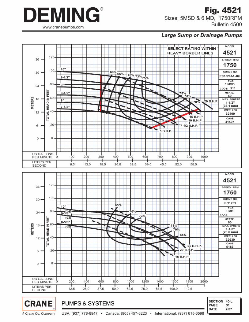
Fig. 4521Sizes: 5MSD & 6 MD, 1750RPM
Bulletin 4500
7/07
SECTION
PAGE
DATE
USA: (937) 778-8947 • Canada: (905) 457-6223 • International: (937) 615-3598A Crane Co. Company
32
40-L
www.cranepumps.com
Large Sump or Drainage Pumps
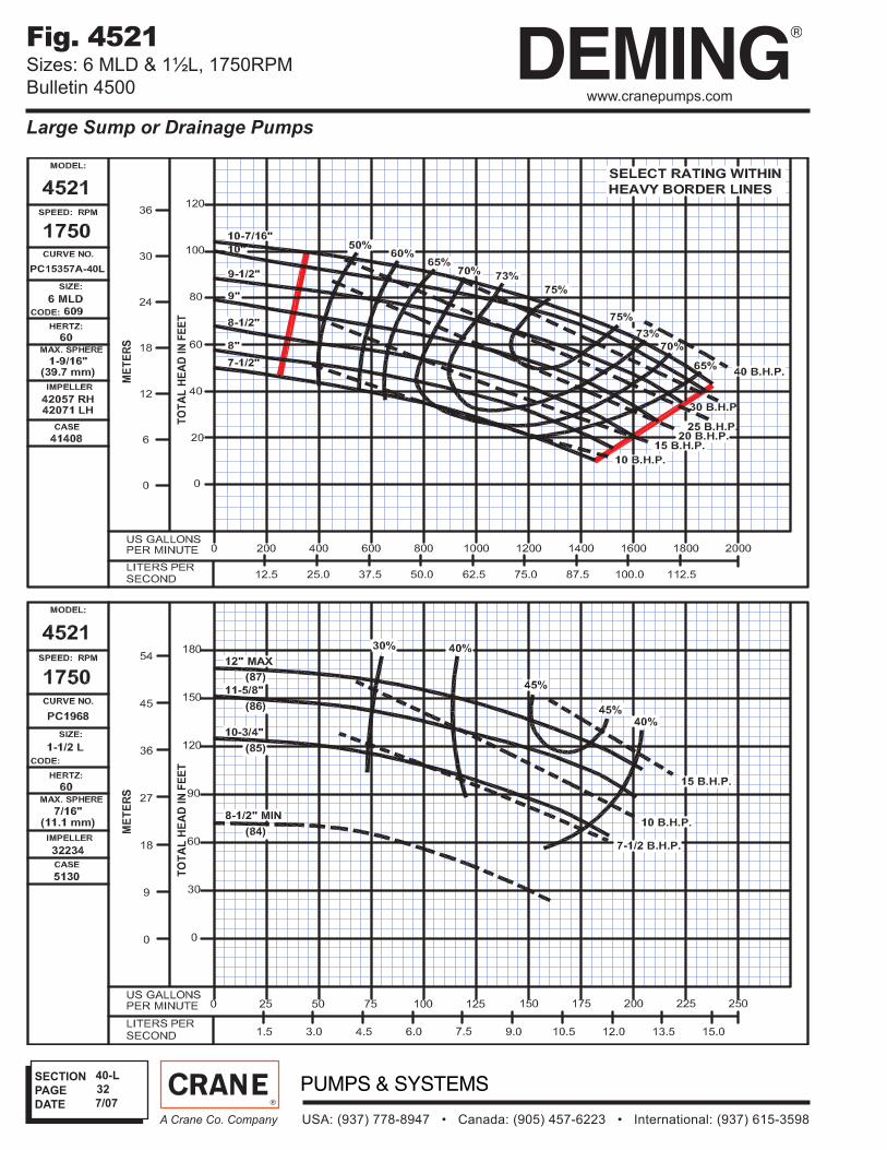
Fig. 4521Sizes: 6 MLD & 1½L, 1750RPM
Bulletin 4500
7/07
SECTION
PAGE
DATE
USA: (937) 778-8947 • Canada: (905) 457-6223 • International: (937) 615-3598A Crane Co. Company
33
40-L
www.cranepumps.com
Large Sump or Drainage Pumps
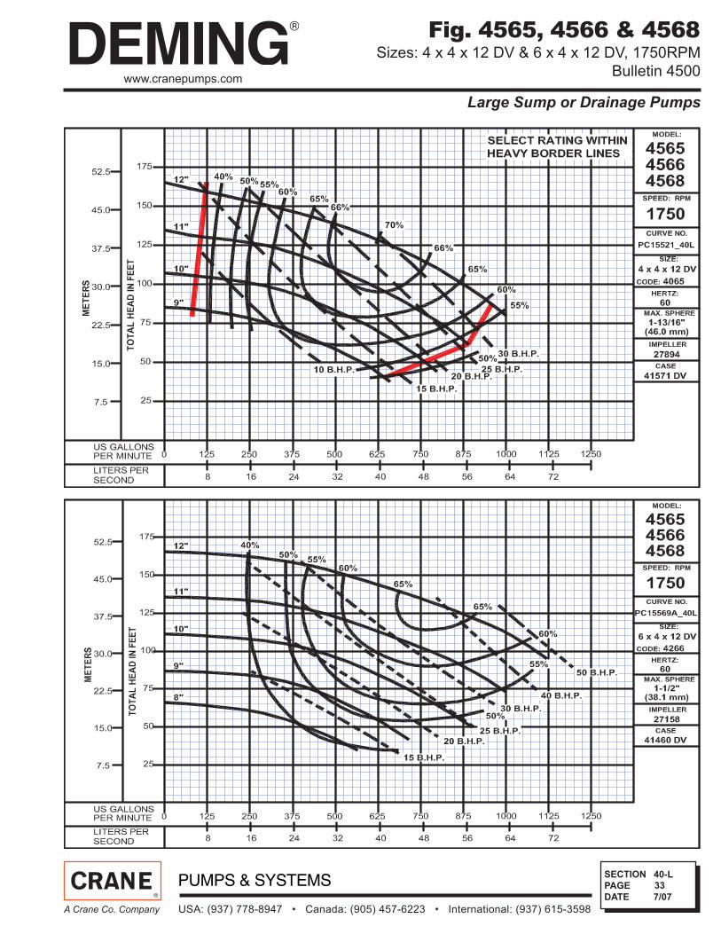
Fig. 4565, 4566 & 4568Sizes: 4 x 4 x 12 DV & 6 x 4 x 12 DV, 1750RPM
Bulletin 4500
7/07
SECTION
PAGE
DATE
USA: (937) 778-8947 • Canada: (905) 457-6223 • International: (937) 615-3598A Crane Co. Company
34
40-L
www.cranepumps.com
Large Sump or Drainage Pumps
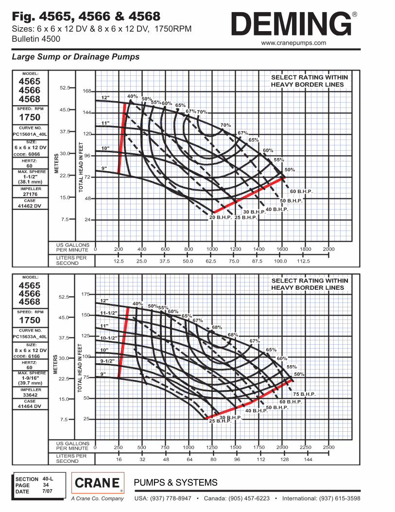
Fig. 4565, 4566 & 4568Sizes: 6 x 6 x 12 DV & 8 x 6 x 12 DV, 1750RPM
Bulletin 4500
7/07

SECTION
PAGE
DATE
USA: (937) 778-8947 • Canada: (905) 457-6223 • International: (937) 615-3598A Crane Co. Company
35
40-L
www.cranepumps.com
Large Sump or Drainage Pumps
Fig. 4565, 4566 & 4568Sizes: 8 x 8 x 12 DV, 1750RPM
Bulletin 4500
7/07
SECTION
PAGE
DATE
USA: (937) 778-8947 • Canada: (905) 457-6223 • International: (937) 615-3598A Crane Co. Company
36
40-L
www.cranepumps.com
Large Sump or Drainage Pumps
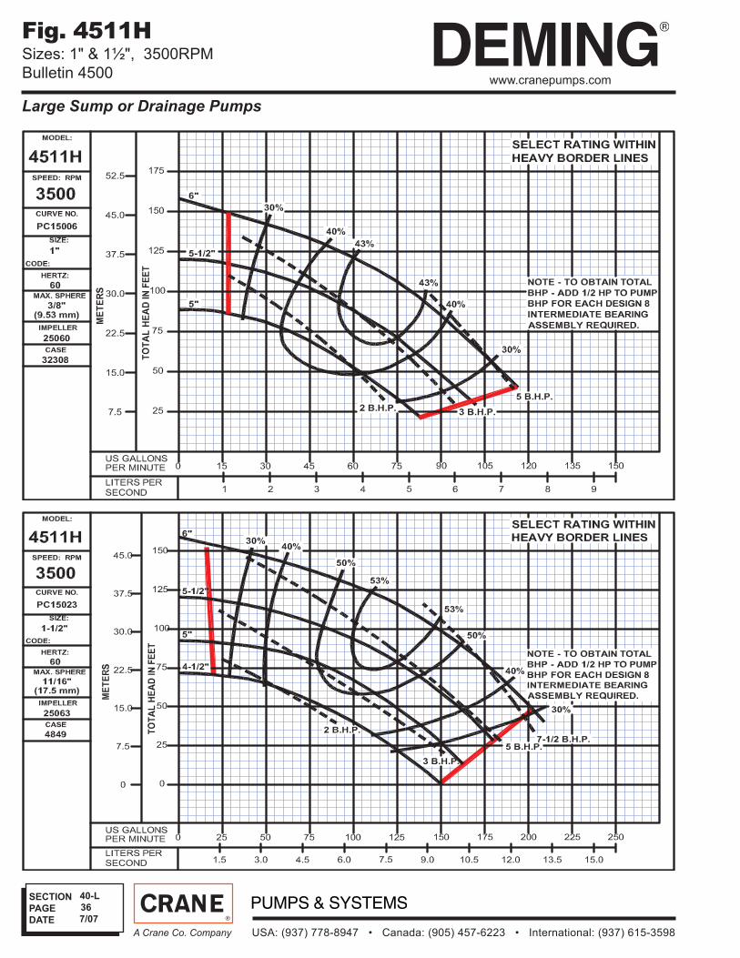
Fig. 4511HSizes: 1" & 1½", 3500RPM
Bulletin 4500
7/07
SECTION
PAGE
DATE
USA: (937) 778-8947 • Canada: (905) 457-6223 • International: (937) 615-3598A Crane Co. Company
37
40-L
www.cranepumps.com
Large Sump or Drainage Pumps
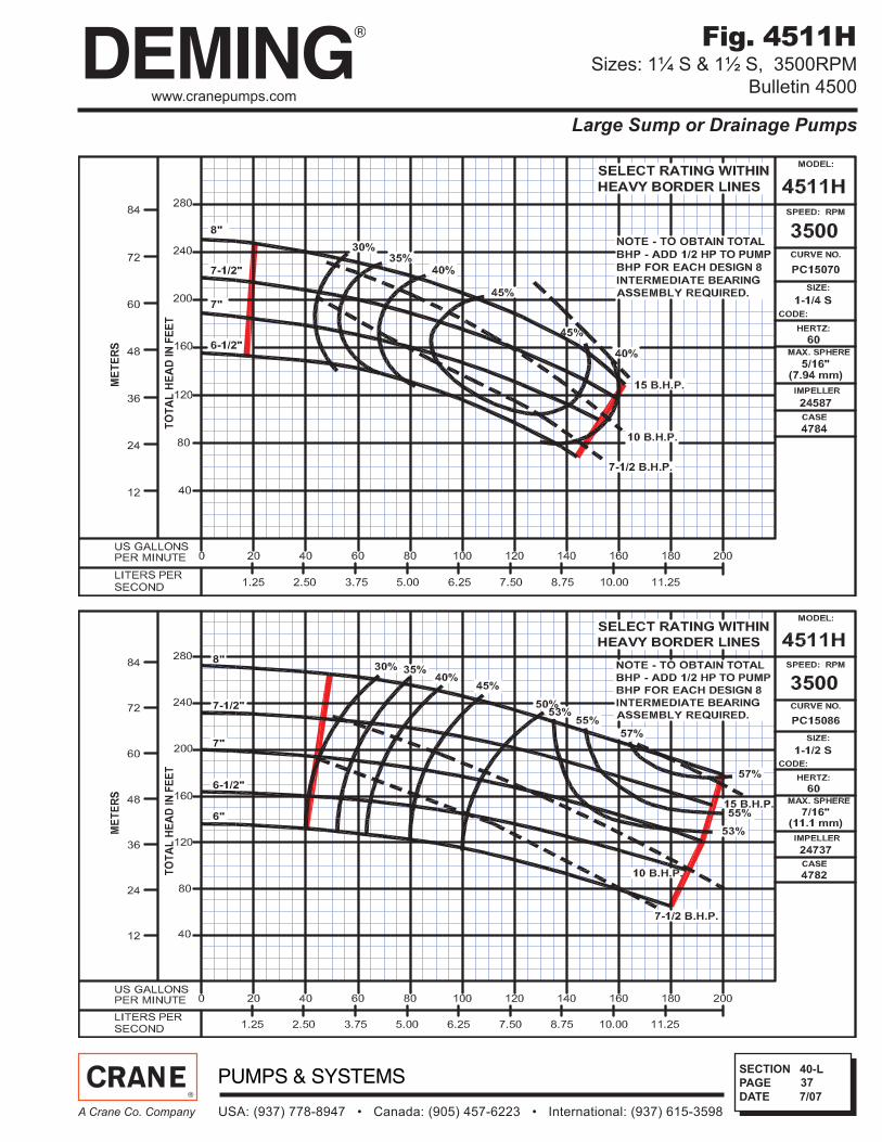
Fig. 4511HSizes: 1¼ S & 1½ S, 3500RPM
Bulletin 4500
7/07

SECTION
PAGE
DATE
USA: (937) 778-8947 • Canada: (905) 457-6223 • International: (937) 615-3598A Crane Co. Company
38
40-L
www.cranepumps.com
Large Sump or Drainage Pumps
Fig. 4511HSizes: 2 S & 3 MD, 3500RPM
Bulletin 4500
7/07