IND560 Technical Manual - Brady Systems · This manual describes features and functions of the...
224
IND560 Terminal User’s Guide www.mt.com 71209394 (09/2010).05
Transcript of IND560 Technical Manual - Brady Systems · This manual describes features and functions of the...

IND560
Terminal User’s Guide
www.mt.com
71209394 (09/2010).05
© METTLER TOLEDO 2010
No part of this manual may be reproduced or transmitted in any form or by any means, electronic or mechanical, including photocopying and recording, for any purpose without the express written permission of METTLER TOLEDO.
U.S. Government Restricted Rights: This documentation is furnished with Restricted Rights.
Copyright 2010 METTLER TOLEDO. This documentation contains proprietary information of METTLER TOLEDO. It may not be copied in whole or in part without the express written consent of METTLER TOLEDO.
METTLER TOLEDO reserves the right to make refinements or changes to the product or manual without notice.
COPYRIGHT
METTLER TOLEDO® is a registered trademark of Mettler-Toledo, Inc. All other brand or product names are trademarks or registered trademarks of their respective companies.
METTLER TOLEDO RESERVES THE RIGHT TO MAKE REFINEMENTS OR CHANGES WITHOUT NOTICE.
FCC Notice
This device complies with Part 15 of the FCC Rules and the Radio Interference Requirements of the Canadian Department of Communications. Operation is subject to the following conditions: (1) this device may not cause harmful interference, and (2) this device must accept any interference received, including interference that may cause undesired operation.
This equipment has been tested and found to comply with the limits for a Class A digital device, pursuant to Part 15 of FCC Rules. These limits are designed to provide reasonable protection against harmful interference when the equipment is operated in a commercial environment. This equipment generates, uses, and can radiate radio frequency energy and, if not installed and used in accordance with the instruction manual, may cause harmful interference to radio communications. Operation of this equipment in a residential area is likely to cause harmful interference in which case the user will be required to correct the interference at his or her expense.
Declaration of Conformity is located on the documentation CD.

NOTE ON FIRMWARE VERSIONS
This manual describes features and functions of the IND560 terminal with version 4.xx firmware. Terminals with version 3.xx firmware or lower will differ in some areas. The following list indicates the key differences between versions:
New in version 4.xx – optional USB host port; install, backup and restore software via USB; calibration test reports.
New in version 3.xx –operation as a Remote Display, Drive-560 Application Software, DYN-560 Application Software, EtherNet / IP PLC interface, repeat print function, PLC messaging, analog section saturation test and warning, supports selection of Tare or Target Table record via PC or PLC, Scale branch accessibility (view only) when Approved, added a Reset Transaction Counter softkey to home screen, updated MinWeigh™ formula, and added various new Shared Data variables.
Version 3.01 firmware is specifically required for operation of the Modbus-TCP interface
Statement regarding harmful substances
We do not make direct use of harmful materials such as asbestos, radioactive substances or arsenic compounds. However, we purchase components from third party suppliers, which may contain some of these substances in very small quantities.

CUSTOMER FEEDBACK Your feedback is important to us! If you have a problem with this product or its documentation, or a suggestion on how we can serve you better, please fill out and send this form to us. Or, send your feedback via email to: [email protected]. If you are in the United States, you can mail this postpaid form to the address on the reverse side or fax it to (614) 438-4355. If you are outside the United States, please apply the appropriate amount of postage before mailing.
Your Name: Date: Organization Name: METTLER TOLEDO Order Number: Address: Part / Product Name: Part / Model Number: Serial Number: Company Name for Installation: Phone Number: ( ) Fax Number: ( ) Contact Name: E-mail Address: Phone Number:
Please check the appropriate box to indicate how well this product met your expectations in its intended use? Met and exceeded my needs Met all needs Met most needs Met some needs Did not meet my needs Comments/Questions:
DO NOT WRITE IN SPACE BELOW; FOR METTLER TOLEDO USE ONLY
Retail Light Industrial Heavy Industrial Custom Response: Include Root Cause Analysis and Corrective Action Taken.

FOLD THIS FLAP FIRST
NO POSTAGE NECESSARY
IF MAILED IN THEUNITED STATES
BUSINESS REPLY MAIL
FIRST CLASS PERMIT NO. 414 COLUMBUS, OH
POSTAGE WILL BE PAID BY ADDRESSEE
Mettler-Toledo, Inc. Quality Manager - MTWT P.O. Box 1705 Columbus, OH 43216 USA
Please seal with tape

PRECAUTIONS
• READ this manual BEFORE operating or servicing this equipment and FOLLOW these instructions carefully.
• SAVE this manual for future reference.
WARNING! FOR CONTINUED PROTECTION AGAINST SHOCK HAZARD CONNECT TO PROPERLY GROUNDED OUTLET ONLY. DO NOT REMOVE THE GROUND PRONG.
WARNING! IN ORDER TO INSTALL THE DIVISION 2 APPROVED IND560 PANEL-MOUNT OR HARSH TERMINAL UTILIZING THE U.S. APPROVAL, METTLER TOLEDO CONTROL DRAWING 72186884R MUST BE FOLLOWED WITHOUT EXCEPTION. IN ORDER TO INSTALL THE CATEGORY 3 IND560 PANEL-MOUNT OR HARSH TERMINAL UTILIZING THE EUROPEAN APPROVAL, THE DEMKO APPROVAL CERTIFICATE 06ATEX0514991X AND ALL LOCAL REGULATIONS MUST BE FOLLOWED WITHOUT EXCEPTION. FAILURE TO DO SO COULD RESULT IN BODILY HARM AND/OR PROPERTY DAMAGE. REFER TO THE IND560 DIVISION 2 AND ZONE 2/22 INSTALLATION GUIDE 64060405 FOR ADITIONAL INFORMATION.
WARNING! EARLIER MODELS OF THE IND560 TERMINAL THAT ARE NOT MARKED (FACTORY LABELED) AS DIVISION 2 OR EUROPEAN CATEGORY 3 APPROVED MUST NOT BE INSTALLED IN A DIVISION 2 OR ZONE2/22 ENVIRONMENT.
WARNING! THIS EQUIPMENT IS SUITABLE FOR USE IN CLASS I, DIVISION 2, GROUPS A, B, C AND D; CLASS II, GROUPS F AND G; CLASS III HAZARDOUS LOCATIONS OR NON-HAZARDOUS LOCATIONS ONLY.
WARNING! SUBSTITUTION OF COMPONENTS MAY IMPAIR SUITABILITY FOR CLASS I, DIVISION 2.
WARNING! DO NOT DISCONNECT EQUIPMENT UNLESS POWER HAS BEEN SWITCHED OFF, OR THE AREA IS KNOWN TO BE NON-HAZARDOUS

WARNING! IF THE KEYBOARD, DISPLAY LENS OR ENCLOSURE IS DAMAGED ON A DIVISION 2 APPROVED OR CATEGORY 3 MARKED IND560 PANEL-MOUNT OR HARSH TERMINAL THAT IS USED IN A DIVISION 2 OR ZONE 2/22 AREA, THE DEFECTIVE COMPONENT MUST BE REPAIRED IMMEDIATELY. REMOVE AC POWER IMMEDIATELY AND DO NOT REAPPLY AC POWER UNTIL THE DISPLAY LENS, KEYBOARD OR ENCLOSURE HAS BEEN REPAIRED OR REPLACED BY QUALIFIED SERVICE PERSONNEL. FAILURE TO DO SO COULD RESULT IN BODILY HARM AND/OR PROPERTY DAMAGE.
WARNING! NOT ALL VERSIONS OF THE IND560 ARE DESIGNED FOR USE IN HAZARDOUS (EXPLOSIVE) AREAS. REFER TO THE DATA PLATE OF THE IND560 TO DETERMINE IF A SPECIFIC TERMINAL IS APPROVED FOR USE IN AN AREA CLASSIFIED AS HAZARDOUS BECAUSE OF COMBUSTIBLE OR EXPLOSIVE ATMOSPHERES.
WARNING! WHEN THIS EQUIPMENT IS INCLUDED AS A COMPONENT PART OF A SYSTEM, THE RESULTING DESIGN MUST BE REVIEWED BY QUALIFIED PERSONNEL WHO ARE FAMILIAR WITH THE CONSTRUCTION AND OPERATION OF ALL COMPONENTS IN THE SYSTEM AND THE POTENTIAL HAZARDS INVOLVED. FAILURE TO OBSERVE THIS PRECAUTION COULD RESULT IN BODILY HARM AND/OR PROPERTY DAMAGE.
WARNING! To avoid damage to the PCB or load cell, remove power from the IND560 TERMINAL and wait at least 30 seconds before connecting or disconnecting any harness.
WARNING! THIS EQUIPMENT IS SUITABLE FOR USE IN CLASS I, DIVISION 2, GROUPS A, B, C, AND D; CLASS II GROUPS F AND G; CLASS III; HAZARDOUS LOCATIONS OR NON-HAZARDOUS LOCATIONS ONLY.
WARNING! DO NOT INSTALL, DISCONNECT OR PERFORM ANY SERVICE ON THIS EQUIPMENT BEFORE POWER HAS BEEN SWITCHED OFF OR THE AREA HAS BEEN SECURED AS NON-HAZARDOU BY PERSONNEL AUTHORIZED TO DO SO BY THE RESPONSIBLE PERSON ON-SITE.

WARNING! ONLY THE COMPONENTS SPECIFIED IN THIS MANUAL CAN BE USED IN THIS TERMINAL. ALL EQUIPMENT MUST BE INSTALLED IN ACCORDANCE WITH THE INSTALLATION INSTRUCTIONS DETAILED IN THIS MANUAL. INCORRECT OR SUBSTITUTE COMPONENTS AND/OR DEVIATION FROM THESE INSTRUCTIONS CAN IMPAIR THE SAFETY OF THE TERMINAL AND COULD RESULT IN BODILY INJURY AND/OR PROPERTY DAMAGE.
CAUTION BEFORE CONNECTING/DISCONNECTING ANY INTERNAL ELECTRONIC COMPONENTS OR INTERCONNECTING WIRING BETWEEN ELECTRONIC EQUIPMENT ALWAYS REMOVE POWER AND WAIT AT LEAST THIRTY (30) SECONDS BEFORE ANY CONNECTIONS OR DISCONNECTIONS ARE MADE. FAILURE TO OBSERVE THESE PRECAUTIONS COULD RESULT IN DAMAGE TO OR DESTRUCTION OF THE EQUIPMENT AND/OR BODILY HARM.
CAUTION OBSERVE PRECAUTIONS FOR HANDLING ELECTROSTATIC SENSITIVE DEVICES.

IND560
Terminal
Essential Services for Dependable Performance of Your IND560 Terminal
Congratulations on choosing the quality and precision of METTLER TOLEDO. Proper use of your new equipment according to this Manual and regular calibration and maintenance by our factory-trained service team ensures dependable and accurate operation, protecting your investment. Contact us about a ServiceXXL agreement tailored to your needs and budget. Further information is available at www.mt.com/serviceXXL.
There are several important ways to ensure you maximize the performance of your investment:
1. Register your product: We invite you to register your product at www.mt.com/productregistration so we can contact you about enhancements, updates and important notifications concerning your product.
2. Contact METTLER TOLEDO for service: The value of a measurement is proportional to its accuracy – an out of specification scale can diminish quality, reduce profits and increase liability. Timely service from METTLER TOLEDO will ensure accuracy and optimize uptime and equipment life.
a. Installation, Configuration, Integration and Training: Our service representatives are factory-trained, weighing equipment experts. We make certain that your weighing equipment is ready for production in a cost effective and timely fashion and that personnel are trained for success.
b. Initial Calibration Documentation: The installation environment and application requirements are unique for every industrial scale so performance must be tested and certified. Our calibration services and certificates document accuracy to ensure production quality and provide a quality system record of performance.
c. Periodic Calibration Maintenance: A Calibration Service Agreement provides on-going confidence in your weighing process and documentation of compliance with requirements. We offer a variety of service plans that are scheduled to meet your needs and designed to fit your budget.
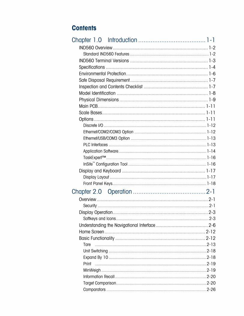
Contents
Chapter 1.0 Introduction ......................................1-1 IND560 Overview....................................................................... 1-2
Standard IND560 Features.................................................................1-2 IND560 Terminal Versions .......................................................... 1-3 Specifications ............................................................................ 1-4 Environmental Protection............................................................. 1-6 Safe Disposal Requirement .......................................................... 1-7 Inspection and Contents Checklist ................................................ 1-7 Model Identification .................................................................... 1-8 Physical Dimensions .................................................................. 1-9 Main PCB................................................................................ 1-11 Scale Bases............................................................................. 1-11 Options................................................................................... 1-11
Discrete I/O ....................................................................................1-12 Ethernet/COM2/COM3 Option ...........................................................1-12 Ethernet/USB/COM3 Option ..............................................................1-13 PLC Interfaces ................................................................................1-13 Application Software........................................................................1-14 TaskExpert™..................................................................................1-16 InSite™ Configuration Tool ................................................................1-16
Display and Keyboard .............................................................. 1-17 Display Layout ...............................................................................1-17 Front Panel Keys.............................................................................1-18
Chapter 2.0 Operation .........................................2-1 Overview................................................................................... 2-1
Security ...........................................................................................2-1 Display Operation....................................................................... 2-3
Softkeys and Icons............................................................................2-3 Understanding the Navigational Interface....................................... 2-6 Home Screen ........................................................................... 2-12 Basic Functionality ................................................................... 2-12
Tare ...........................................................................................2-13 Unit Switching ................................................................................2-18 Expand By 10 ................................................................................2-18 Print ...........................................................................................2-19 MinWeigh ......................................................................................2-19 Information Recall...........................................................................2-20 Target Comparison..........................................................................2-20 Comparators ..................................................................................2-26

IND560 User’s Guide
ID ...........................................................................................2-27 SmartTrac™....................................................................................2-28 Time and Date................................................................................2-31 Reports..........................................................................................2-31 Calibration Test...............................................................................2-33 CalFREE™.....................................................................................2-34
Alibi Memory Direct Access........................................................ 2-34 Table Searches ........................................................................ 2-35
Remote Display ..............................................................................2-35
Chapter 3.0 Configuration....................................3-1 Entering Setup Mode................................................................... 3-1 Exiting Setup Mode..................................................................... 3-2 Setup Menu Tree ........................................................................ 3-2
Setup Screens...................................................................................3-3 Overview of Configuration............................................................ 3-5 Configuration Options ................................................................. 3-7
Scale .............................................................................................3-7 Remote Display ................................................................................3-8 Application.....................................................................................3-26 Terminal ........................................................................................3-38 Communication ..............................................................................3-46 Maintenance ..................................................................................3-69
Restoring Factory Default Settings............................................... 3-79
Chapter 4.0 Service and Maintenance ...................4-1 Cleaning and Maintenance .......................................................... 4-1 Service...................................................................................... 4-1 Upgrading Firmware ................................................................... 4-2
Upgrading from Version 1.xx Firmware to Version 2.xx, 3.xx or 4.xx ......4-2 Performing an Upgrade with InSite ......................................................4-2 Performing the Upgrade via USB .........................................................4-4 File Locations on USB Drive ...............................................................4-4
Backup and Restore with USB...................................................... 4-4 Backup............................................................................................4-5 Restore ............................................................................................4-6
Changing Screen Saver Graphic ................................................... 4-7 Display Messages ...................................................................... 4-7 Setting a Custom Language......................................................... 4-8 Troubleshooting ......................................................................... 4-8
AC Power Test ..................................................................................4-9 Power Supply Voltage Test .................................................................4-9
IND560 User’s Guide
Battery Test ....................................................................................4-10 Internal Diagnostic Testing ...............................................................4-10 RS-232 Serial Output Voltage Test ....................................................4-13 Master Reset ..................................................................................4-13
External Diagnostics ................................................................. 4-15 View Pages ....................................................................................4-16 Diagnostics & Maintenance Pages....................................................4-20
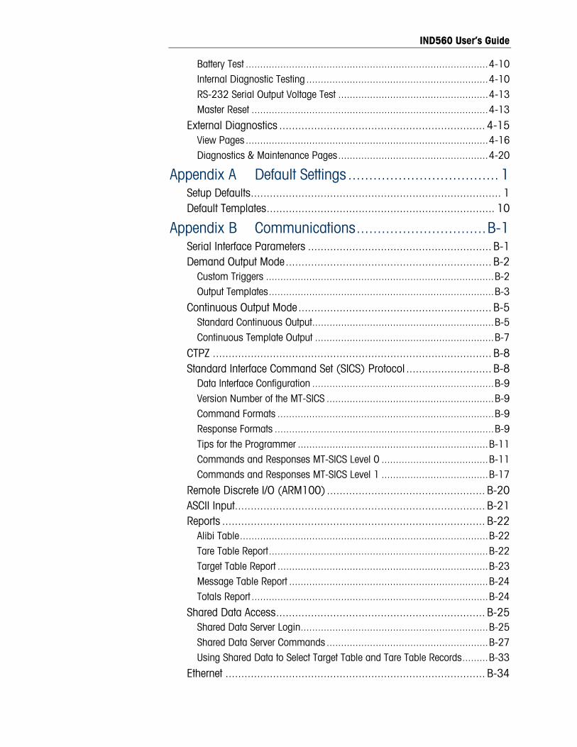
Appendix A Default Settings.................................... 1 Setup Defaults............................................................................... 1 Default Templates........................................................................ 10
Appendix B Communications...............................B-1 Serial Interface Parameters .......................................................... B-1 Demand Output Mode................................................................. B-2
Custom Triggers ...............................................................................B-2 Output Templates..............................................................................B-3
Continuous Output Mode............................................................. B-5 Standard Continuous Output...............................................................B-5 Continuous Template Output ..............................................................B-7
CTPZ ........................................................................................ B-8 Standard Interface Command Set (SICS) Protocol ........................... B-8
Data Interface Configuration ...............................................................B-9 Version Number of the MT-SICS ..........................................................B-9 Command Formats ...........................................................................B-9 Response Formats ............................................................................B-9 Tips for the Programmer ..................................................................B-11 Commands and Responses MT-SICS Level 0 .....................................B-11 Commands and Responses MT-SICS Level 1 .....................................B-17
Remote Discrete I/O (ARM100) .................................................. B-20 ASCII Input............................................................................... B-21 Reports ................................................................................... B-22
Alibi Table......................................................................................B-22 Tare Table Report............................................................................B-22 Target Table Report .........................................................................B-23 Message Table Report .....................................................................B-24 Totals Report ..................................................................................B-24
Shared Data Access.................................................................. B-25 Shared Data Server Login.................................................................B-25 Shared Data Server Commands ........................................................B-27 Using Shared Data to Select Target Table and Tare Table Records.........B-33
Ethernet .................................................................................. B-34

IND560 User’s Guide
Ethernet Connection to a PC .............................................................B-34 Ethernet Demand Output ..................................................................B-37 Ethernet Continuous Output ..............................................................B-39
FTP ........................................................................................ B-40 FTP over Ethernet Example...............................................................B-42
Terminal Updates ..................................................................... B-43 Uploading New Firmware.................................................................B-43 Uploading Customized Softkey Graphics............................................B-43

Chapter 1.0 Introduction
DIV 2 AND ZONE 2/22 INSTALLATION IF YOU WISH TO INSTALL THE IND560 IN A DIVISION 2 OR ZONE 2/22 AREA, REFER TO THE DIVISION 2 AND ZONE 2/22 INSTALLATION INSTRUCTIONS INCLUDED ON THE DOCUMENTATION CD PROVIDED WITH THE TERMINAL. FAILURE TO COMPLY WITH THE INSTRUCTIONS PROVIDED THERE COULD RESULT IN BODILY HARM AND/OR PROPERTY DAMAGE.
The IND560 represents the latest in METTLER TOLEDO technology and is the most versatile weighing terminal available today. Choose from conventional strain gauge or high-precision electromagnetic force restoration weighing technologies. Specify direct PLC or PC communication interfaces or digital I/O control. Combine these selections with the option of panel or desk/wall/column-mounting, and the IND560 is the perfect match for nearly any weighing application in many industries, including:
This chapter covers
• IND560 Overview
• IND560 Terminal Versions
• Specifications
• Safe Disposal Requirement
• Model Identification
• Physical Dimensions • Basic Weighing • In-Motion Weighing
• General Process Weighing • Formulation
• Filling and Blending • Over/Under Checkweighing
• Options and Interfaces
• Display and Keyboard
Enhance measurement or control applications with an ultra-fast A/D conversion rate of 366 Hz, patented TraxDSP™ digital filtering technology, and an I/O bus update rate of 50 Hz. The IND560 delivers precision measurement data from milligrams to tons in a single cost effective package that easily integrates into existing systems.
The versatile IND560 excels in controlling filling and dosing applications delivering best-in-class performance for fast, precise, accurate results in manual, semi-automatic, or fully automatic operations.
The IND560 promotes more cost-effective solutions too. Control up to 18 digital outputs through the IND560 without the use of a PLC. Target outputs are also latched, eliminating the need for external logic devices.
For more advanced filling, the Fill-560 Application Software adds additional sequences and component inputs. Without complex and costly programming, quickly configure standard filling sequences or create custom filling and blending applications for up to four components that cue operators for action and reduce errors.
1-1

IND560 User’s Guide
1-2
Whether communicating weight data to a process PLC or providing an easier way to do terminal configuration via the InSite™ PC Tool, the IND560 offers multiple connectivity options to improve applications.
Direct PLC connectivity is available using 4-20mA Analog Output, Allen-Bradley RIO, PROFIBUS DP, DeviceNet, EtherNet/IP or Modbus TCP protocols. Interfaces are also available for serial data via RS-232/422/485 and Ethernet TCP/IP networking. With the release of v4.00 firmware, a new optional USB interface provides the ability to connect a QWERTY keyboard for operator input. The new USB option can also be used for upgrading terminal firmware and performing a save/restore.
For information about IND560 terminal operation, refer to the IND560 User Guide.
IND560 Overview The IND560 terminal is available in the following versions:
• Harsh enclosure with analog load cell connection
• Harsh enclosure with high-precision (IDNet) base connection
• Panel-mount enclosure with analog load cell connection
• Panel-mount enclosure with high-precision (IDNet) base connection
Standard IND560 Features • Basic weighing terminal used in safe areas
• Panel-mount or harsh desk/wall-mount enclosures
• Connect one analog load cell scale base (or up to eight 350 ohm load cells) or an IDNet base depending upon the version of the IND560
• Operation as a Remote Display for another terminal
• 128 × 64 dot-matrix graphic vacuum fluorescent display (VFD) with 21mm-high weight display
• Real-time clock (battery backup)
• One serial port for asynchronous, bidirectional communication and print output
• 85–264 VAC power input range
• Support for the following option boards:
Analog Output interface Ethernet TCP/IP with dual serial ports USB host with Ethernet TCP/IP and single serial port Allen Bradley RIO® interface DeviceNet™ interface PROFIBUS® DP interface EtherNet/IP interface

IND560 User’s Guide
1-3
Modbus TCP interface Relay Based Discrete I/O interface
• Basic weighing functions including zero, tare, and printing
• Selectable over/under classifying mode of operation with graphics
• Selectable material transfer mode for simple filling or dosing
• ID mode for prompted transaction sequencing
• Comparators, simple coincidence setpoints for comparison of weight or Rate with absolute target values or ranges
• SmartTrac™ graphical display
• Two memory tables—25 Tare records and 25 Target records
• Unit switching between three different units including custom units
• Alibi memory storage for up to 60,000 records
• Grand total and subtotal registers for accumulating weight
• Five customizable print templates and report printing
• TraxDSP™ digital filtering for analog load cells
• TraxEMT™ performance monitoring and recording
• CalFREE™ calibration without test weights
• Support of the following Application Software Modules:
Fill-560 Drive-560
COM-560 Dyn-560
• Support for TaskExpert™ custom application development software
IND560 Terminal Versions The IND560 terminal is available in the following versions:
• Harsh enclosure with analog load cell connection
• Harsh enclosure with high-precision (IDNet) base connection
• Panel-mount enclosure with analog load cell connection
• Panel-mount enclosure with high-precision (IDNet) base connection

IND560 User’s Guide
1-4
Specifications The IND560 terminal conforms to the specifications listed in Table 1-1.
Table 1-1: IND560 Specifications
IND560 Specifications
Panel-mount stainless steel front panel with an aluminum frame
Enclosure Type
Harsh environment desk/wall/column-mount type 304L stainless steel enclosure
Panel Mount: 265 mm × 160 mm × 92 mm (10.4 in. × 6.3 in. × 3.6 in.)
Dimensions (l × w × d)
Harsh Environment: 265 mm × 160 mm × 170 mm (10.4 in. × 6.3 in. × 6.7 in.)
Shipping Weight 3.5 kg (8 lb)
Panel-mount front panel sealing is UL-approved, and provides type 4x and type 12 protection – comparable to IP65 rating
Environmental Protection
Harsh Environment is UL-approved, and meets IP69K requirements
Operating Environment The terminal (both enclosure types) can be operated at temperatures ranging from −10° to 40° C (14° to 104° F) at 10% to 95% relative humidity non-condensing.
Hazardous Areas Not all versions of the IND560 can be operated in areas classified as Hazardous by the National Electrical Code (NEC) because of the combustible or explosive atmospheres in those areas. Contact an authorized METTLER TOLEDO representative for information about hazardous applications.
Operates at 85–264 VAC, 49–61 Hz, 750 mA (both enclosure types).
Panel-mount version provides a terminal strip for AC power connections.
Harsh environment version includes a power cord configured for the country of use.
Power
Note: When an IND560 is installed in an area classified as Division 2 or Zone 2/22, special AC wiring requirements must be met. See document 64060405, IND560 Division 2, Zone 2/22 Installation Guide.
Power Consumption Refer to Table 1-2

IND560 User’s Guide
1-5
IND560 Specifications
Display 128 × 64 dot-matrix graphic VFD display, 21 mm Display Update Rate: 10/second
Weight Display Displayed resolution of 100,000 counts for analog load cell scales Display resolution for high-precision IDNet bases is determined by the specific base used
Scale Types Analog load cells or IDNet, High-Precision K Line (T-Brick type standard)
Number of Cells Eight 350-ohm load cells (2 or 3 mv/V)
Number of Scales Interface for one analog or one IDNet scale
Analog/Digital Update Rates Internal: Analog: >366 Hz; IDNet: determined by base; Target Comparison: 50 Hz; PLC Interface: 20 Hz
Load Cell Excitation Voltage 10 VDC
Minimum Sensitivity 0.1 microvolts
Keypad 25 keys; 1.22-mm thick polyester overlay (PET) with polycarbonate display lens
Communications Serial Interfaces Standard Serial port:
• COM1 (RS-232/RS-422/RS-485), 300 to 115,200 baud
Optional Ethernet/Serial Port/USB(s): • Ethernet 10 Base-T with two additional serial
ports, COM2 (RS-232) and COM3 (RS-232/ RS-422 / RS-485)
or • Ethernet 10 Base-T with one additional serial
port, COM3 (RS-232/RS-485), and one USB host port
Protocol Serial Inputs: ASCII characters, ASCII commands for CTPZ (Clear, Tare, Print, Zero), SICS (most level 0 and level 1 commands) Serial Outputs: Continuous or Demand with up to five configurable print templates or SICS host protocol, report printing, interfaces with external ARM100 Remote Input/Output modules. Optional COM-560 Application Software available for legacy serial protocols.

IND560 User’s Guide
1-6
IND560 Specifications
Approvals Weights and Measures
USA: NTEP Class II 100,000d; Class III/IIIL 10,000d; CoC #05-057A2
Canada: Class II 100,000d; Class III 10,000d; Class IIIHD, 20,000d; AM-5593
Europe: OIML Class II approved divisions determined by platform; Class III 10,000e; Class IIII 1,000e; Includes Alibi Memory; TC6812
Australia: Class III 7,500e or 3 x 3,000e multiple range; NMI S483
Hazardous Area
ATEX
Harsh/Analog: II 3 G EEx nL [nL] IIB T4 Panel/Analog & IDNet : II 3 G EEx nL [nL] IIB T4 II 3 D T85°C IP6X cULus Harsh/Analog: CL I, GP A-D Div 2; CL II, GP F,G Div 2; CL III; Zone 2 GP IIC; -10°C<=Ta<=+40°C Panel/Analog & IDNet : CL I, GP A-D Div 2; CL II, GP F,G Div 2; CL III; Zone 2 GP IIC; -10°C<=Ta<=+40°C
Product Safety UL, cUL, CE
Table 1-2: IND560 Power Consumption
U (V) P (W) I (mA)
85V/50 Hz 70 822
264 V/50 Hz 156 603
85 V/60 Hz 69 810
264 V/50 Hz 147 558
110 V/50 Hz 84 766
110 V/60 Hz 86 784
240 V/50 Hz 147 614
240 V/60 Hz 145 603
Test condition: IND560 with internal Ethernet/Serial, Analog Output and Discrete I/O options installed, input loaded to simulate 8 x 350 load cells.

IND560 User’s Guide
1-7
Environmental Protection
WARNING! THE STANDARD IND560 IS NOT INTRINSICALLY SAFE! DO NOT USE IN AREAS CLASSIFIED AS HAZARDOUS BY THE NATIONAL ELECTRICAL CODE (NEC) BECAUSE OF COMBUSTIBLE OR EXPLOSIVE ATMOSPHERES.
When an approved IND560 is installed in an area classified as Division 2 or Zone 2/22, special AC wiring requirements must be met. See document 64060405, IND560 Division 2, Zone 2/22 Installation Guide.
Safe Disposal Requirement
In conformance with the European Directive 2002/96/EC on Waste Electrical and Electronic Equipment (WEEE) this device may not be disposed of in domestic waste. This also applies to countries outside the EU, per their specific requirements.
Please dispose of this product in accordance with local regulations at the collecting point specified for electrical and electronic equipment.
If you have any questions, please contact the responsible authority or the distributor from which you purchased this device.
Should this device be passed on to other parties (for private or professional use), the content of this regulation must also be related.
Thank you for your contribution to environmental protection.
Inspection and Contents Checklist Verify the contents and inspect the package immediately upon delivery. If the shipping container is damaged, check for internal damage and file a freight claim with the carrier if necessary. If the container is not damaged, remove the IND560 terminal from its protective package, noting how it was packed, and inspect each component for damage.
If shipping the terminal is required, it is best to use the original shipping container. The IND560 terminal must be packed correctly to ensure its safe transportation.
The package should include:
IND560 Terminal
Installation manual
Documentation CD (includes all manuals)
Bag of parts including ferrites, grommets, etc., depending on terminal configuration
IND560 User’s Guide
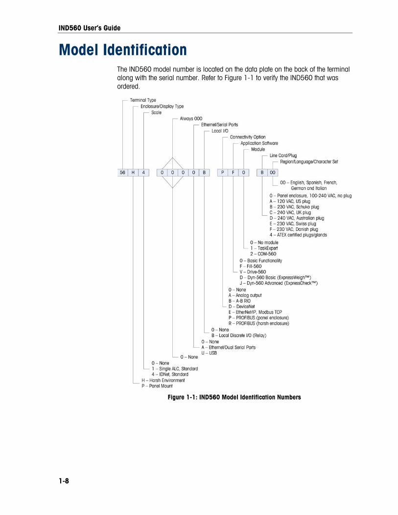
Model Identification The IND560 model number is located on the data plate on the back of the terminal along with the serial number. Refer to Figure 1-1 to verify the IND560 that was ordered.
Figure 1-1: IND560 Model Identification Numbers
1-8

IND560 User’s Guide
Physical Dimensions The physical dimensions of the Panel Mount IND560 enclosure are shown in Figure 1-2 in inches and [mm]. Figure 1-3 shows the dimensions of the cutout required for the Panel Mount enclosure.
Figure 1-2: IND560 Panel Mount Enclosure Dimensions
Figure 1-3: IND560 Panel Mount Cutout Dimensions
1-9

IND560 User’s Guide
The dimensions of the harsh enclosure desk/wall-mount IND560 terminal are shown in Figure 1-4 and Figure 1-5 in inches and [mm].
Figure 1-4: Harsh Environment Enclosure Dimensions
Figure 1-5: Harsh Environment Enclosure Dimensions with Optional Brackets
1-10

IND560 User’s Guide
1-11
Main PCB The IND560 terminal’s main printed circuit board (PCB) provides the scale interface for analog load cell or IDNet.
The main board also contains the COM1 serial port that provides RS-232, RS-422, or RS-485 communication. The port is bidirectional and can be configured for various functions such as demand output, SICS host communications, continuous output, ASCII command input (C, T, P, Z), ASCII character input, report printing, totals printing, or connection to an ARM100 remote I/O module.
The main board also contains the AC power input connections, front panel keyboard interface and bus connectors for the option boards.
Scale Bases The IND560 supports two types of scale bases: Analog or IDNet.
Analog Load Cell Scale Base The IND560 supports this scale type by an analog load cell interface. The terminal can drive up to eight 350-ohm analog load cells.
IDNet™ Scale Base The IND560 supports the newer T-brick style of high-precision base through the main board IDNet port. This port provides the +12 volts and communication required to operate this newer style base. The older K module and Pik-brick cells require the addition of an adapter board and new power supply (to support the +32 volt requirement) to the IND560. The adapter board and power supply are available as an option.
Initial performance and compatibility testing was carried out on the IND560 and the following modules: K15, F15, K32 and T-Brick. Compatibility with other modules and bases is unknown.
Options The following options are available for the IND560:
• Discrete I/O
Internal, high-level discrete I/O and remote discrete I/O via ARM100 module
• Ethernet/COM2/COM3 Serial Ports option
• Ethernet/USB/COM3 serial port option
• Programmable Logic Control (PLC) interfaces, including:
Analog Output Allen-Bradley® RIO DeviceNet™
IND560 User’s Guide
PROFIBUS® DP EtherNet/IP™ Modbus TCP
• Fill-560 (application software)
• Drive-560 (application software)
• COM-560 (application software)
• Dyn-560 Basic and Advanced (application software)
• TaskExpert™ application development software
• Installation kit for older pre-2003 high-precision bases using a PIK-Brick weigh cell
• InSite™ Configuration Tool
• Various brackets for wall and column mounting of the harsh enclosure
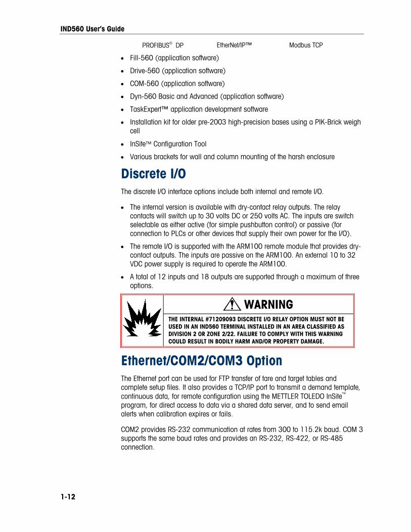
Discrete I/O The discrete I/O interface options include both internal and remote I/O.
• The internal version is available with dry-contact relay outputs. The relay contacts will switch up to 30 volts DC or 250 volts AC. The inputs are switch selectable as either active (for simple pushbutton control) or passive (for connection to PLCs or other devices that supply their own power for the I/O).
• The remote I/O is supported with the ARM100 remote module that provides dry-contact outputs. The inputs are passive on the ARM100. An external 10 to 32 VDC power supply is required to operate the ARM100.
• A total of 12 inputs and 18 outputs are supported through a maximum of three options.
WARNING THE INTERNAL #71209093 DISCRETE I/O RELAY OPTION MUST NOT BE USED IN AN IND560 TERMINAL INSTALLED IN AN AREA CLASSIFIED AS DIVISION 2 OR ZONE 2/22. FAILURE TO COMPLY WITH THIS WARNING COULD RESULT IN BODILY HARM AND/OR PROPERTY DAMAGE.
Ethernet/COM2/COM3 Option The Ethernet port can be used for FTP transfer of tare and target tables and complete setup files. It also provides a TCP/IP port to transmit a demand template, continuous data, for remote configuration using the METTLER TOLEDO InSite™ program, for direct access to data via a shared data server, and to send email alerts when calibration expires or fails.
COM2 provides RS-232 communication at rates from 300 to 115.2k baud. COM 3 supports the same baud rates and provides an RS-232, RS-422, or RS-485 connection.
1-12

IND560 User’s Guide
1-13
Ethernet/USB/COM3 Option The Ethernet port can be used for FTP transfer of tare and target tables and complete setup files. It also provides a TCP/IP port to transmit a demand template, continuous data, for remote configuration using the METTLER TOLEDO InSite™ program, for direct access to data via a shared data server, and to send email alerts when calibration expires or fails.
COM3 supports an RS-232, RS-422, or RS-485 connection at communication rates from 300 to 115.2k baud.
The USB port provides a USB host that supports an external QWERTY keyboard. Keyboard languages supported are English, French, German, Italian and Spanish. The new USB option can also be used for upgrading terminal firmware and performing a save/restore.
Use of the Ethernet/USB/Serial option board requires version 4.xx firmware or higher.
PLC Interfaces The IND560 PLC interface options include Analog Output, A-B RIO, DeviceNet, PROFIBUS DP, EtherNet/IP and Modbus TCP. Additional details about each of these interfaces can be found in the IND560 PLC Interface Manual, provided on the documentation CD.
Analog Output Analog Output refers to the representation of an internal system variable using a proportional electrical signal. Analog Output can be used to transmit a measured value, such as the gross or net weight. Another use for Analog Output is as a control signal for some external device, such as a control valve, where the amount of valve opening is proportional to the analog signal commanding its operation. Such outputs are used to control the flow rate of material into or out of a vessel.
Both 0-10 volt DC and 4-20 mA signals are provided.
A-B RIO The A-B RIO option enables data exchange by bi-directional communications using the Discrete Data Transfer or Block Transfer mode. The IND560 Terminal initiates a communication exchange with the PLC approximately 20 times per second utilizing the Allen-Bradley Discrete Data Transfer protocol. This communication is a high-speed, real-time message interface between the IND560 Terminal and the PLC for process control. Division, integer, and floating point values are supported.
The IND560 A-B RIO interface also supports Block Transfer mode for transmission of larger amounts of data.

IND560 User’s Guide
1-14
DeviceNet DeviceNet is an RS-485 based network utilizing CAN chip technology. This network was created for bit and byte-level devices. The network can be configured to run up to 500Kbits per second depending on cabling and distances. Messages are limited to 8 unfragmented bytes. The network can include up to 64 nodes including the master, commonly called the scanner.
PROFIBUS DP The IND560 Terminal communicates to a PROFIBUS-DP master according to DIN 19 245. The PROFIBUS option consists of a module and software that resides in the IND560 Terminal, which implements the data exchange.
EtherNet/IP The IND560 supports communications of the EtherNet/IP interface option and the appropriate driver software.
Modbus TCP Modbus/TCP is used to establish master-slave/client-server communication between intelligent devices. It is an open standard network protocol, widely used in the industrial manufacturing environment. The ModbusTCP protocol takes the Modbus instruction set and wraps TCP/IP around it. The Modbus TCP protocol is supported by the EtherNet/IP interface board, version 1.32 or higher.
Application Software
Installing Application Software When a hardware key (also referred to as an iButton) enabling IND560 application software is installed or removed, a pop-up message will appear instructing the user to perform a master reset. The master reset can be performed with or without resetting metrologically significant EEPROM (Scale) data, depending on the positions of switches SW2-1 and SW2-2. Both of these switches must be set to ON in order to reset EEPROM data to its factory default values. If either of them is set to OFF, EEPROM data is preserved. Refer to Chapter 4 of this manual, Service and Maintenance, for details on performing a master reset.
Fill-560 The Fill-560 is a special application that can be added to the IND560 terminal to provide additional filling and dosing control. It provides control for the following combinations of weigh-in and weigh-out sequences.
• Fill only • Fill and dose out • Blend and dose out
• Fill and dump • Blend only
• Dose out only • Blend and dump

IND560 User’s Guide
1-15
Additional information can be found in the Fill-560 Manual on the documentation CD that accompanies the Fill-560 software kit or an IND560fill terminal.
COM-560 The COM-560 option is a specialized software module solution focused on the needs of users utilizing legacy communication protocols or that have special command requirements. The IND560com maintains all of the standard features and functions of the IND560 in addition to the specific features and functions of the COM-560. It provides the following features and functions:
• Custom ASCII command template • Mettler Toledo Continuous Short output • 8142 Host Protocol
• 8530 Host Protocol • PT6S3 Protocol
Additional information can be found in the COM-560 Manual on the module’s documentation CD.
Drive-560 The Drive-560 option is a specialized application solution focused on simple inbound-outbound vehicle weighing requirements. The IND560drive has two modes of operation: Temporary Tare ID Weighing and Permanent Tare ID Weighing. Some features of this software include:
• Ability to store up to 100 Permanent Tare IDs
• Totalization of Permanent Tare IDs
• One-Step processing of Temporary IDs
• Reprint of previous transaction ticket
• Storage of up to 2000 transactions
Additional information can be found in the Drive-560 Manual on the documentation CD that accompanies an IND560drive terminal.
Dyn-560 The Dyn-560 optional modules are specialized application solutions used for in-motion weighing of conveyor-born packages. They can be used with up to four 350 Ω load cells, and are compatible with the METTLER TOLEDO 9477 weighing conveyor. The IND560dyn is a stand-alone terminal. When that terminal is packaged with a variety of I/O options, it is known as the IND9D56. Both types are equipped with a version of the Dyn-560 software, which can be specified in either ExpressWeigh® or ExpressCheck® form.
ExpressWeigh functionality provides accurate in-motion package weighing with ID and additional data input. ExpressCheck includes an enhanced version of ExpressWeigh, and adds the ability to perform three-zone over/under checkweighing, using comparisons with a Target Table.
IND560 User’s Guide
Additional information can be found in the Dyn-560 manuals found on the documentation CD that accompanies an IND560dyn or application software kit.
Special Requirements for Using Drive-560 and Dyn-560 Required Firmware Version
The Drive-560 and Dyn-560 applications are both written using Task Expert™. To run a TaskExpert application, the IND560 must have version 3.xx firmware or higher installed.
Required Mainboard Version
In addition to the software, the IND560 must have a main board version (V0.8) installed. V0.8 main boards include 8MB of Flash Memory. The version can be checked by pressing the Recall Info softkey then the System Information softkey
, and looking at the details for the analog or IDNet board under Hardware – Scale Type. If there is a (V0.8) after the Analog L/C or IDNet text, the main board contains the 8MB Flash Memory and will support running a TaskExpert application. If the version is (V0.2) or there is no version shown, there is only 4 MB of Flash Memory on the main board and the board must be replaced with a V0.8 version before the terminal can run a TaskExpert application.
Main boards with the smaller, 4MB, Flash Memory will support v3.00 firmware. However, they will not support Task Expert based applications such as the Drive-560 and Dyn-560.
TaskExpert™ TaskExpert functionality provides a way to modify the standard capabilities of an IND560 so that it more closely aligns with the application requirements. TaskExpert is a combination of a programming visualization tool, an execution engine and the basic functionality of the terminal. Modifications may be made to the sequence of operation and additional functionality added to the basic operation of the terminal.
InSite™ Configuration Tool The IND560 terminal can connect to a PC running InSite via Ethernet or Serial to provide the following:
• Viewing and/or changing configuration.
• Enabling device-free configuration work before hardware installation.
• Saving configuration information locally on the PC, loading a saved configuration file into other devices, or restoring to a known state for service purposes.
1-16

IND560 User’s Guide
• WYSIWYG print template editing tool with expanded viewing area, cut/paste functions, stored clipboard library (MyData items), and template space usage display.
• Printing documentation of configuration for users’ records.
• Performing firmware upgrade services for the IND560.
Display and Keyboard The IND560 terminal has a Vacuum Fluorescent Display (VFD), 128 × 64 dot matrix graphic type display. An example of the IND560 front panel is shown in Figure 1-6.
1-17
Figure 1-6: The IND560 Front Panel Layout
Display Layout • A system line is reserved at the top to show system messages, messages sent
remotely from a PLC, and any asynchronous errors.
• The middle portion of the display is reserved for the weight display and/or SmartTrac display. Random data entry is shown in the bottom of this area.
• The bottom of the display is reserved for showing the graphic labels (icons) for the softkeys. Display positions for up to five softkey icons are provided.
• To the right of the softkey icon area space is reserved for a MORE UP ( ) or a MORE DOWN ( ) indicator. If present, these indicate additional softkey selections are available by pressing either the UP or DOWN navigation keys. A total of 15 softkeys, presented in three sets of five, are programmable for the home position depending upon the weighing options and terminal functions enabled. The softkey setup and key mapping capabilities of the terminal determine the positioning of the softkeys and locations where they display.
Softkey labels
System line
Sof
ght and WeiApp
tkeys
lication area
Numeric keys
Navigation keys
Zero, Tare, and Print keys

IND560 User’s Guide
1-18
Front Panel Keys Three dedicated scale function keys are located to the right of the display. These provide the interface to zero or tare the scale and to initiate a print.
The terminal’s 12-key numeric keypad is used to enter data and commands. The numeric keys are located on the upper-right side of the terminal front panel.
Five navigation keys are located below the three scale function keys. These keys enable the operator to navigate through setup options in the menu tree and within setup and application screens.
Chapter 2.0 Operation
Overview This chapter covers
• Overview This chapter provides information about navigation, basic functionality, and report generation using the IND560 terminal. • Understanding the Navigational
Interface
Operation of the terminal depends on enabled functions and parameters that are configured in setup as described in Chapter 3.0, Configuration. Navigation and basic functionality, as well as basic report generation are covered in the following sections.
• Home Screen
• Basic Functionality
• Alibi Memory Direct Access
• Table Searches
Security The IND560 supports the use of username/password for setup security at four levels. Refer to Appendix B to determine security levels assigned to specific parameters in setup.
Administrator An Administrator has unlimited access to all areas of the operating and setup system. There can be multiple Administrator accounts. There is a Primary Administrator account, which can be changed but never deleted. The terminal is pre-configured at the factory with the Primary Administrator account with a username of “admin”. The factory default password is null (no password). The pre-configured username (admin) cannot be changed; the password can only be added or modified. The unit as configured at the factory requires no login or password entry to enter the setup mode. All functions of the terminal are available to all users until a password for the Primary Administrator account is set up.
When the Metrology switch (SW1-1) is turned “on” (refer to the next section of this chapter) and a region approval is selected in setup, all users with Administrator rights are reduced to the Maintenance level. This is done to protect metrologically significant parameters that cannot be changed when the terminal is approved.
Similarly, the metrology switch can also be used to prevent Administrator level users from accessing metrology features even if the region approval is “None”.
Refer to Appendix B, Default Settings, for the security level of all setup parameters.
Once a password is set up, be sure to remember the password. If the password is changed or forgotten, access to the setup menu will not be
2-1

IND560 User’s Guide
2-2
available. Be sure to protect the password from access by unauthorized personnel. The password provides access to the entire setup menu, unless the metrology switch is placed in the approved position.
Maintenance Access can be limited by configuring this security level as desired. Supervisor Access can be limited by configuring this security level as desired.
Operator One default operator account with a username of anonymous and password null (no password) is provided. Sites with validation requirements might create many operator accounts, each with a username and password entry requirement.
If a password has been programmed for the Primary Administrator username in Setup, a security challenge is presented when entering Setup and a username and password must be entered. The user can enter a password at any security level supported by the User configuration in the User setup.
The terminal is pre-configured at the factory to include an “anonymous” user account with a null (blank) password. The default anonymous user record can be edited or deleted. The user can increase to a higher level of security clearance by requesting a setup function and then meeting the associated security challenge.
If a login fails, the display exits the login page and returns to the home position.
Metrology Switch If the metrology switch (SW1-1) is placed in the approved position (On) access to the Scale branch of setup and other metrologically significant areas is not permitted. The metrology switch can be used to prevent Administrator level users from accessing metrology features even if the region approval is “None”.
Selecting a specific region approval and turning “on” the Metrology switch specifically alters some scale functions:
If the approval is Canada, then the keyboard tare command carries out a rounded tare.
If the approval is Canada, then the center of zero division is 0.2d. The default value for non-approved mode is 0.25d.
If the approval is OIML, then the power up zero range is +/- 10% and pushbutton zero range is +/-2%. For non-approved mode, this range can be selected by the user.
Access to the metrology switch may be sealed in conformity with local regulations in “legal-for-trade” applications. Figure 2-1 shows the location of the metrology switch.

IND560 User’s Guide
SW1
Figure 2-1: Metrology Switch Location
Refer to Appendix A, Installation, PCB Switch Settings for further information about SW1-1 and SW1-2 switch settings.
Display Operation Key names and commands are identified in this manual by upper- and lower-case letters. Key names, such as ENTER, are in all upper-case letters, and commands, such as “select,” are in lower-case (unless they begin a sentence, in which case the first initial is upper-case). For example:
“Press START...” means to press the START softkey .
“Select an option...” means to use the UP or DOWN navigation keys to select a setting, then press ENTER.
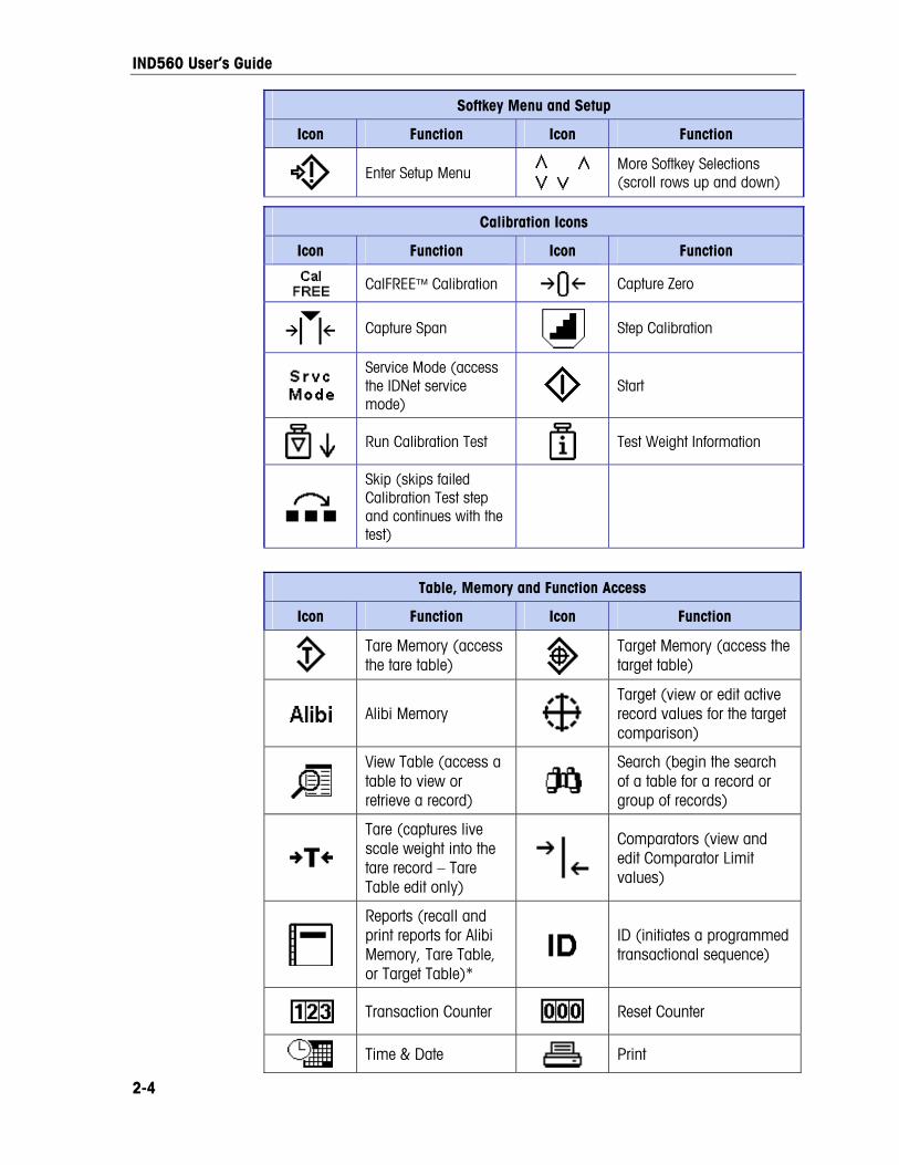
Softkeys and Icons Softkeys and application displays use graphic icons for identification. Table 2-1 shows graphic icons and their functions, categorized by where they are used. Items with an asterisk (*) require a supervisor level log-in or above to be in effect.
Table 2-1: Icons and Functions
Information Recall Options
Icon Function Icon Function
Clear All*
Recall information
Clear Subtotal* System Information Recall
Metrology Recall
Total Recall
Print*
Weight Recall
2-3
IND560 User’s Guide
Softkey Menu and Setup
Icon Function Icon Function
Enter Setup Menu
More Softkey Selections (scroll rows up and down)
Calibration Icons
Icon Function Icon Function
CalFREE™ Calibration Capture Zero
Capture Span
Step Calibration
Service Mode (access the IDNet service mode)
Start
Run Calibration Test Test Weight Information
Skip (skips failed Calibration Test step and continues with the test)
Table, Memory and Function Access
Icon Function Icon Function
Tare Memory (access the tare table)
Target Memory (access the target table)
Alibi Memory
Target (view or edit active record values for the target comparison)
View Table (access a table to view or retrieve a record)
Search (begin the search of a table for a record or group of records)
Tare (captures live scale weight into the tare record – Tare Table edit only)
Comparators (view and edit Comparator Limit values)
Reports (recall and print reports for Alibi Memory, Tare Table, or Target Table)*
ID (initiates a programmed transactional sequence)
Transaction Counter
Reset Counter
Time & Date Print
2-4

IND560 User’s Guide
Table, Memory and Function Access
Icon Function Icon Function
Repeat Print
Customized Print Triggers 1, 2 and 3
Editing
Icon Function Icon Function
Clear All* Exit (return to previous screen)
Delete
Insert
Edit
Validate Entry/Transaction (OK)
Escape (exit without storing) Copy
Display Icons
Icon Function Icon Function
Times 10 Display (expands the displayed weight by 10)
SmartTrac (turns SmartTrac display off and on)
MinWeigh (enter MinWeigh mode)
Unit Switching
Special Control
Icon Function Icon Function
Target Control
Start
Pause
Stop
No Clear Total*
Reset
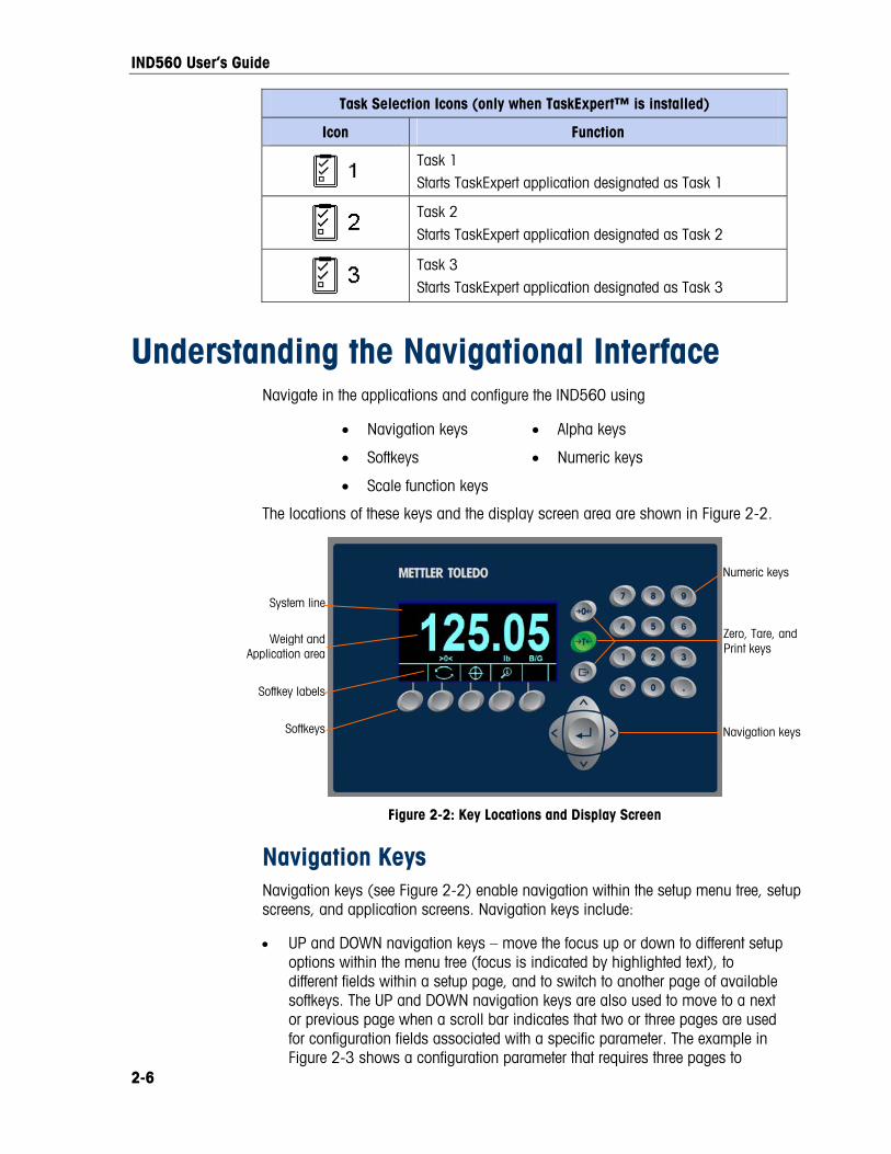
Task Selection Icons (only when TaskExpert™ is installed)
Icon Function
Task List Displays list of assigned TaskExpert applications
2-5
IND560 User’s Guide
Task Selection Icons (only when TaskExpert™ is installed)
Icon Function
Task 1 Starts TaskExpert application designated as Task 1
Task 2 Starts TaskExpert application designated as Task 2
Task 3 Starts TaskExpert application designated as Task 3
Understanding the Navigational Interface Navigate in the applications and configure the IND560 using
• Navigation keys • Alpha keys
• Softkeys • Numeric keys
• Scale function keys
The locations of these keys and the display screen area are shown in Figure 2-2.
Numeric keys
Softkey labels
System line
Softkeys
Weight and Application area
Navigation keys
Zero, Tare, and Print keys
Figure 2-2: Key Locations and Display Screen
Navigation Keys Navigation keys (see Figure 2-2) enable navigation within the setup menu tree, setup screens, and application screens. Navigation keys include:
• UP and DOWN navigation keys – move the focus up or down to different setup options within the menu tree (focus is indicated by highlighted text), to different fields within a setup page, and to switch to another page of available softkeys. The UP and DOWN navigation keys are also used to move to a next or previous page when a scroll bar indicates that two or three pages are used for configuration fields associated with a specific parameter. The example in Figure 2-3 shows a configuration parameter that requires three pages to
2-6

IND560 User’s Guide
display all of the associated configuration fields. The scroll bars indicate which page of the three is displayed.
Scroll bar indicating page 1 of 3
Scroll bar indicating
page 2 of 3
Scroll bar indicating page 3 of 3
Figure 2-3: Example of Scroll Bars, Indicating Three Pages of Configuration Fields
Press the DOWN navigation key to move from page 1 to 2 or from page 2 to 3. Press the UP navigation key to move from page 3 to 2 or page 2 to 1.
• LEFT and RIGHT navigation keys
Expand (RIGHT navigation key) the setup options in the menu tree
Collapse (LEFT navigation key) the setup options in the menu tree
Move the cursor position to a specific character in text areas
Enable left and right scrolling to view all information available on a screen
• ENTER key
Opens the setup page for viewing and editing setup parameters
Moves the focus from a field label to a setup value for that field
Accepts new values entered in a field and moves the focus to the next field label
Softkeys There is a softkey setup page that is used to
• Change softkey positions
• Enable softkey functions
• Disable softkey functions
For example, a UNIT SWITCHING softkey can be enabled for selecting alternate units of measure.
Five softkeys are located along the bottom of the display screen (see Figure 2-2). Some applications might have up to three pages of softkeys for a total of 15 possible functions. A MORE DOWN symbol displayed on the lower-right corner of the screen (to the far right of the softkey icons) indicates that more softkey
2-7

IND560 User’s Guide
selections are available. Press the DOWN navigation key to display additional softkey screens, and UP to display the previous softkey screen.
Appendix E, Softkey Mapping, explains how softkeys can be configured in setup.
Customizing Softkeys
All the softkeys available for assignment to the home screen can be replaced with customized bitmap images.
The bitmaps must measure no more than 23 pixels wide by 15 pixels high. Each graphic must have a white border at least one pixel wide at left, right and top – see Figure 2-4.
Figure 2-4: Softkey Graphic Dimensions
Graphics may be uploaded to the IND560 terminal using an ftp connection via Ethernet, or through a serial port. Refer to Appendix D, Communications, for details on these procedures.
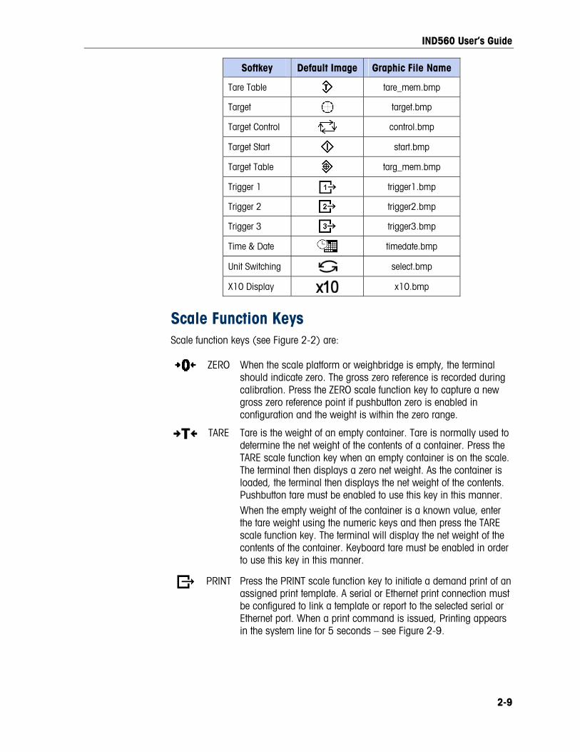
New bitmap graphics must have the same filename as the graphic they replace. Table 2-2 lists the softkey graphics that can be replaced with customized images.
Table 2-2: Bitmap Graphic Filenames
Softkey Default Image Graphic File Name
Alibi alibi.bmp
Calibration Test cal_test.bmp
Comparators comprtr.bmp
ID Id.bmp
MinWeigh minweigh.bmp
Recall Info recall.bmp
Reports reports.bmp
Setup setup.bmp
SmartTrac sm_trac.bmp
2-8
IND560 User’s Guide
Softkey Default Image Graphic File Name
Tare Table tare_mem.bmp
Target target.bmp
Target Control control.bmp
Target Start start.bmp
Target Table targ_mem.bmp
Trigger 1 trigger1.bmp
Trigger 2 trigger2.bmp
Trigger 3 trigger3.bmp
Time & Date timedate.bmp
Unit Switching select.bmp
X10 Display x10.bmp
Scale Function Keys Scale function keys (see Figure 2-2) are:
ZERO When the scale platform or weighbridge is empty, the terminal should indicate zero. The gross zero reference is recorded during calibration. Press the ZERO scale function key to capture a new gross zero reference point if pushbutton zero is enabled in configuration and the weight is within the zero range.
TARE Tare is the weight of an empty container. Tare is normally used to determine the net weight of the contents of a container. Press the TARE scale function key when an empty container is on the scale. The terminal then displays a zero net weight. As the container is loaded, the terminal then displays the net weight of the contents. Pushbutton tare must be enabled to use this key in this manner. When the empty weight of the container is a known value, enter the tare weight using the numeric keys and then press the TARE scale function key. The terminal will display the net weight of the contents of the container. Keyboard tare must be enabled in order to use this key in this manner.
PRINT Press the PRINT scale function key to initiate a demand print of an assigned print template. A serial or Ethernet print connection must be configured to link a template or report to the selected serial or Ethernet port. When a print command is issued, Printing appears in the system line for 5 seconds – see Figure 2-9.
2-9
IND560 User’s Guide
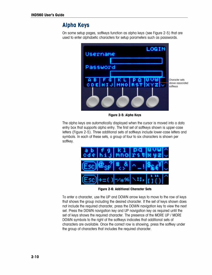
Alpha Keys On some setup pages, softkeys function as alpha keys (see Figure 2-5) that are used to enter alphabetic characters for setup parameters such as passwords.
Character sets above associated softkeys
Figure 2-5: Alpha Keys
The alpha keys are automatically displayed when the cursor is moved into a data entry box that supports alpha entry. The first set of softkeys shown is upper-case letters (Figure 2-5). Three additional sets of softkeys include lower-case letters and symbols. In each of these sets, a group of four to six characters is shown per softkey.
Figure 2-6: Additional Character Sets
To enter a character, use the UP and DOWN arrow keys to move to the row of keys that shows the group including the desired character. If the set of keys shown does not include the required character, press the DOWN navigation key to view the next set. Press the DOWN navigation key and UP navigation key as required until the set of keys shows the required character. The presence of the MORE UP / MORE DOWN symbols to the right of the softkeys indicates that additional sets of characters are available. Once the correct row is showing, press the softkey under the group of characters that includes the required character.
2-10
IND560 User’s Guide
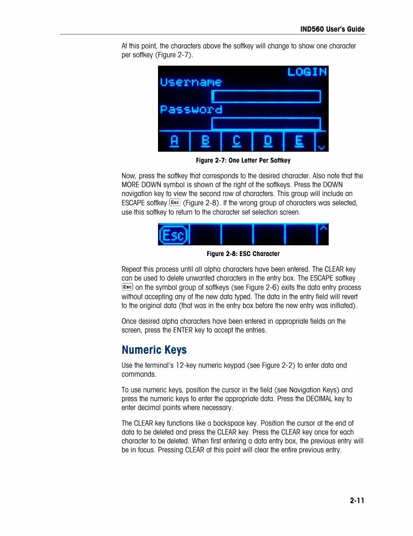
At this point, the characters above the softkey will change to show one character per softkey (Figure 2-7).
Figure 2-7: One Letter Per Softkey
Now, press the softkey that corresponds to the desired character. Also note that the MORE DOWN symbol is shown at the right of the softkeys. Press the DOWN navigation key to view the second row of characters. This group will include an ESCAPE softkey (Figure 2-8). If the wrong group of characters was selected, use this softkey to return to the character set selection screen.
Figure 2-8: ESC Character
Repeat this process until all alpha characters have been entered. The CLEAR key can be used to delete unwanted characters in the entry box. The ESCAPE softkey
on the symbol group of softkeys (see Figure 2-6) exits the data entry process without accepting any of the new data typed. The data in the entry field will revert to the original data (that was in the entry box before the new entry was initiated).
Once desired alpha characters have been entered in appropriate fields on the screen, press the ENTER key to accept the entries.
Numeric Keys Use the terminal’s 12-key numeric keypad (see Figure 2-2) to enter data and commands.
To use numeric keys, position the cursor in the field (see Navigation Keys) and press the numeric keys to enter the appropriate data. Press the DECIMAL key to enter decimal points where necessary.
The CLEAR key functions like a backspace key. Position the cursor at the end of data to be deleted and press the CLEAR key. Press the CLEAR key once for each character to be deleted. When first entering a data entry box, the previous entry will be in focus. Pressing CLEAR at this point will clear the entire previous entry.
2-11

IND560 User’s Guide
Home Screen The Home screen displays when the terminal is idle. The Home screen is the only screen that provides operator access to the programmable softkeys. Figure 2-9 shows a sample screen with a message showing in the system line.
System line
Application area
MORE DOWN symbol indicating more Softkey selections
Softkey icons
Figure 2-9: Default Home Screen, System Line with Message Showing
The Home Screen includes:
• System Line Displays system messages and application data
• Application Area Displays weight, units, and other application-specific weighing data
• Softkey Icons Displays the icons for the active softkey functions. The appearance of a MORE DOWN symbol or a MORE UP
symbol indicates that more softkey selections are available
Basic Functionality This section provides information about the IND560’s basic functionality. Additional areas of functionality specific to application software available for the IND560 are addressed in the specific application manuals. Basic functions addressed in this section include:
• Zero • Information Recall • Reports
• Tare • Target Comparison • Calibration Test
• Unit Switching • Comparators • CalFREE™
• Expand By 10 • ID Mode • Alibi Memory
• Print • SmartTrac • Table Searches
• MinWeigh • Time and Date • Remote Display
2-12

IND560 User’s Guide
Zero The Zero function is used to set or reset the initial zero reference point of the IND560. There are three types of zero setting modes:
• Automatic Zero Maintenance
• Power-Up
• Pushbutton
Automatic Zero Maintenance
Automatic Zero Maintenance (AZM) enables the IND560 to compensate for the build up of small amounts of weight and track itself back to the center of zero. Within the AZM operating range (programmable from 0.00 to 10.00 divisions), when the terminal is in a no motion condition, it makes small adjustments to the current zero reading to drive the weight reading toward the true center-of-zero. When the weight is outside of the programmed AZM range, this feature is not functional.
Power-Up Zero
Power-Up Zero enables the IND560 terminal to capture a new zero reference point after power is applied. If there is motion during a power-up zero capture function, the terminal will continue to check for a no-motion condition until zero is captured.
Power-up zero can be disabled or enabled, and a range above and below calibrated zero can be configured. The range is programmable from 0% to 100% of capacity and can include a positive range and also a range below calibrated zero.
Pushbutton Zero
The pushbutton (semi-automatic) zero function can be accomplished by pressing the ZERO scale function key, programming a discrete input, a PLC command or serial command, or by an application.
The range for all types of semi-automatic zero is selectable (0% to 100%) plus or minus from either the calibrated zero point (if power-up zero is disabled) or from the initial zero setting point (if power-up zero is enabled).
Remote initiation of the semi-automatic Zero command is possible via a discrete input, an ASCII ‘Z’ command sent serially (CPTZ and SICS), a command initiated by the PLC interface, or from an application.
Tare Tare is the weight of an empty container. A tare value subtracts from the gross weight measurement, providing the computation of the net weight (material without the container). The tare function can also be used to track the net amount of material being added to or removed from a vessel or container. In this second case, the weight of the material in the container is included with the tare weight of
2-13

IND560 User’s Guide
the container as tare. The display then reflects the net amount being added to or removed from the vessel.
Tare types and associated operations available on the IND560 include:
• Pushbutton Tare • Tare Clear
• Keyboard Tare (Preset Tare) — Manual Clear
• Net Sign Correction — Auto Clear
• Auto Tare
Pushbutton Tare Pushbutton tare can be configured in setup as enabled or disabled. When disabled, the TARE scale function key cannot be used to obtain a tare.
If enabled, pressing the pushbutton TARE scale function key initiates a semi-automatic tare. The IND560 will attempt to perform a tare process. If successful, the display changes to a zero net weight indication and the previous weight on the scale is stored as the tare value. The net mode will be indicated on the display.
Several conditions could inhibit the pushbutton tare function:
• Motion – Pushbutton tare cannot be taken when the scale is in motion. If motion is detected when a pushbutton tare command is received, the IND560 will wait up to three seconds for a no-motion condition. If a stable (no motion) weight condition occurs before the three seconds expire, the pushbutton tare command is executed.
• If there is still motion at the end of three seconds, the command is aborted and a “Tare Failure–In Motion” error displays.
• Pushbutton Tare Disabled – If pushbutton tare is configured as disabled, the TARE scale function key will not initiate a semi-automatic tare.
• Negative Gross Weight – Any pushbutton tare attempted when the gross weight is at or below zero is ignored and a “Tare Failed–Too Small” error displays. Ensure that the gross weight is above zero.
Keyboard Tare A keyboard (preset) tare is a numeric tare that is entered manually through the numeric keypad, received serially from a peripheral, or retrieved from the Tare Table memory. The preset tare value cannot exceed the capacity of the scale. Data entered is interpreted to have the same units as the current displayed value. Motion does not impact the entry of preset tare values.
Keyboard tare can be configured in setup as enabled or disabled. When disabled, the numeric keypad and the TARE scale function key cannot be used to obtain a tare.
2-14

IND560 User’s Guide
To enter a preset tare value manually, use the numeric keypad to enter the tare value (the data entered will display above the softkey with a Data: label) and press the TARE scale function key .
If configured in setup, remote equipment can enter a preset tare value using a serial command or PLC command (see Chapter 3.0, Configuration, the Communication section, Serial and PLC setup, for further information).
If the preset tare is successful, the display changes to a net weight indication, and the entered preset tare value is stored as the tare value in the Tare Table.
Several conditions could inhibit the preset tare function:
• Keyboard Tare Disabled – If keyboard tare is configured in setup as disabled, the numeric keypad and the TARE scale function key cannot be used to obtain a tare.
• Over-Capacity or Under-Zero Conditions – Preset tare is not allowed when the weight display indicates over capacity or under zero conditions. Any preset tare attempted when the scale is over capacity is ignored and a “Tare Failed–Over Cap” error displays. Any preset tare attempted when the weight display indicates an under zero condition is ignored and a “Tare Failed–Too Small” error displays.
Preset tare can be entered in free format. If the entered value does not match the displayed weight decimal point location or display interval, the entered tare value is rounded to the nearest display interval and the decimal point adjusted to match the gross weight. The rounding method is that 0.5 or more of a display interval (d) is increased to the next display interval and 0.49 or less of a display interval is decreased to the next lower display interval.
When entering a preset tare value less than 1.0, the operator can enter the data without the leading zero (left of the decimal point), but all subsequent display, storage, or printing of this value will include the leading zero. For example, a preset tare entry of .05 will display as 0.05.
If a preset tare has already been established and another preset tare is entered, the second preset tare replaces the previous value (it does not add to the previous value). The replacement tare can be larger or smaller than the original tare value.
Tare Table The IND560 terminal contains a tare table with 25 records for storing tare weights that can be recalled by the operator, instead of manually entering them for each transaction. This is especially useful when certain tare values are used repeatedly.
A 20 character description can be included for each record. This can be used to help distinguish one tare record from another. Each tare record in the tare table also contains a totalization field. When totalization is enabled for the tare table, each time a transaction is completed using a specific tare ID, the selected weight value (gross or net weight) will be added to the total and the corresponding counter will be incremented by one.
2-15
IND560 User’s Guide
2-16
A tare memory can be recalled by either picking from a list of all available records or if the ID for the tare value is know, it can be “quick” accessed (refer to the Quick Access section, below). A printed report of the records in the Tare Table is also available. Additional details about the tare table are explained in Appendix C, Table and Log File Structure.
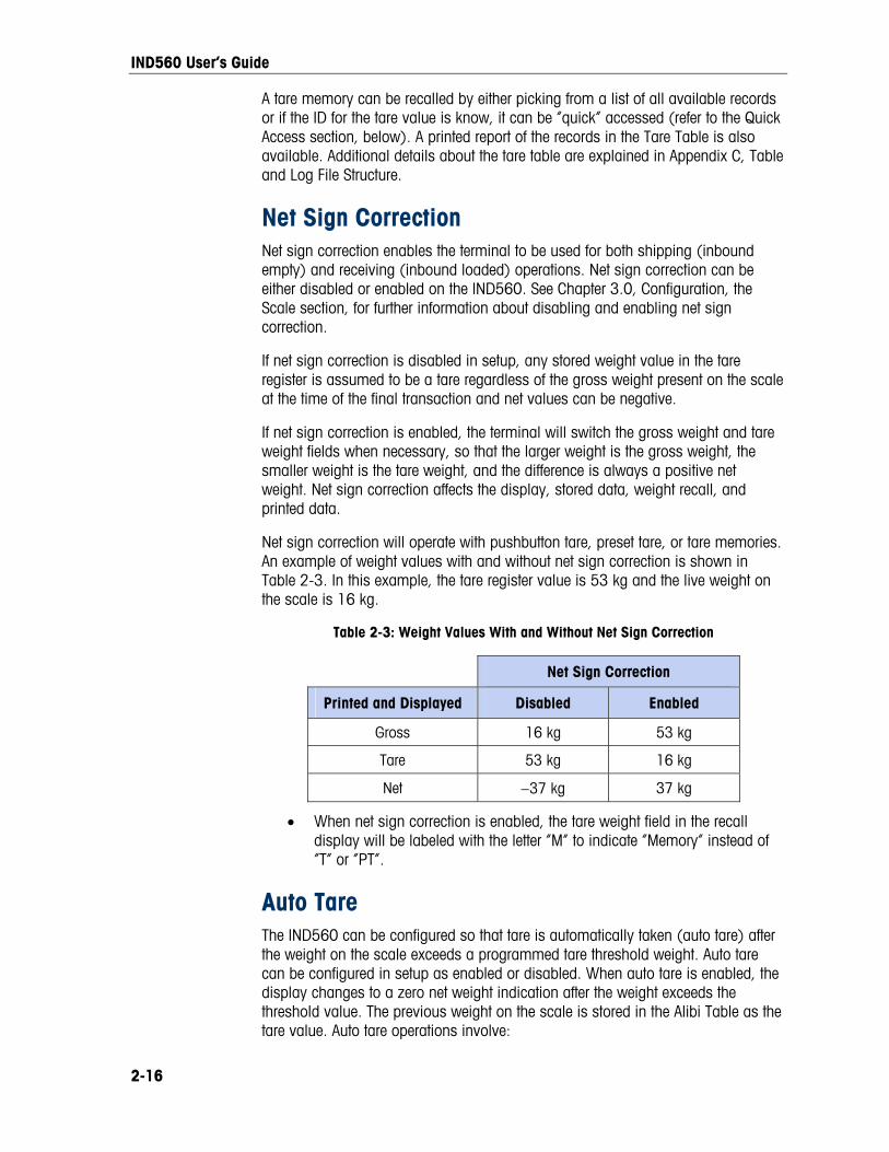
Net Sign Correction Net sign correction enables the terminal to be used for both shipping (inbound empty) and receiving (inbound loaded) operations. Net sign correction can be either disabled or enabled on the IND560. See Chapter 3.0, Configuration, the Scale section, for further information about disabling and enabling net sign correction.
If net sign correction is disabled in setup, any stored weight value in the tare register is assumed to be a tare regardless of the gross weight present on the scale at the time of the final transaction and net values can be negative.
If net sign correction is enabled, the terminal will switch the gross weight and tare weight fields when necessary, so that the larger weight is the gross weight, the smaller weight is the tare weight, and the difference is always a positive net weight. Net sign correction affects the display, stored data, weight recall, and printed data.
Net sign correction will operate with pushbutton tare, preset tare, or tare memories. An example of weight values with and without net sign correction is shown in Table 2-3. In this example, the tare register value is 53 kg and the live weight on the scale is 16 kg.
Table 2-3: Weight Values With and Without Net Sign Correction
Net Sign Correction
Printed and Displayed Disabled Enabled
Gross 16 kg 53 kg
Tare 53 kg 16 kg
Net −37 kg 37 kg
• When net sign correction is enabled, the tare weight field in the recall display will be labeled with the letter “M” to indicate “Memory” instead of “T” or “PT”.
Auto Tare The IND560 can be configured so that tare is automatically taken (auto tare) after the weight on the scale exceeds a programmed tare threshold weight. Auto tare can be configured in setup as enabled or disabled. When auto tare is enabled, the display changes to a zero net weight indication after the weight exceeds the threshold value. The previous weight on the scale is stored in the Alibi Table as the tare value. Auto tare operations involve:

IND560 User’s Guide
• Tare Threshold Weight – When weight on the scale platform exceeds the tare threshold value, the terminal automatically tares.
• Reset Threshold Weight – The reset threshold weight must be less than the tare threshold weight. When the weight on the scale platform falls below the reset threshold value, such as when a load has been removed, the terminal automatically resets the auto tare trigger.
• Motion Check – A motion check is provided to control the re-arming of the auto tare function. If disabled, the auto tare trigger will be reset as soon as the weight falls below the reset value. If enabled, the weight must settle to no-motion below the reset threshold before the next auto tare can be initiated.
Several conditions could inhibit the auto tare function:
• Motion – Auto tare cannot be taken when the scale is in motion. If motion is detected after the weight on the scale exceeds a preset tare threshold weight, the IND560 will wait for a no-motion condition. If a stable (no motion) weight condition occurs within three seconds, the auto tare command is executed.
• Auto Tare Disabled – Auto tare can be configured in setup as enabled or disabled.
Clearing Tare Tare values can be cleared manually or automatically.
Manual Clear
Manually clear tare values by pressing the CLEAR key on the numeric keypad when the IND560 is in the net mode and has completed the weighing operation. Motion on the scale will not impact a manual clear.
If configured in setup, pressing the ZERO scale function key will first clear the tare, then issue a zero command (see Chapter 3.0, Configuration, the Scale section, Auto Clear).
Auto Clear
The IND560 can be configured to clear tare automatically when the weight returns to a value below a programmable threshold, or when a print command is issued. Once the tare is cleared, the display returns to the gross weighing mode.
Auto clear is disabled or enabled in setup. If auto clear is enabled the following parameters, configured in setup, affect the auto clear operation:
• Clear Threshold Weight – The clear threshold weight is the gross weight value below which the IND560 will automatically clear a tare after settling to a value above this threshold value.
• Motion Check – A motion check is provided to control the automatic clearing of tare. If the motion check is disabled, the tare value is cleared as soon as the weight drops below the threshold weight (auto clear threshold), regardless of the motion status.
2-17

IND560 User’s Guide
• If the motion check is enabled, after meeting the requirements for weight value above and then below the threshold weight (auto clear threshold), the IND560 waits for a no-motion condition before automatically clearing the tare.
• Clear After Print – If enabled, tare is automatically cleared and the scale returned to the gross mode after data has been transmitted by pressing the PRINT scale function key or from a remote source.
See Chapter 3.0, Configuration, the Scale section, Auto Clear for further information about configuring auto clear.
Unit Switching In order to support locations and applications that utilize multiple measurement units, the IND560 supports unit switching. The UNIT SWITCHING softkey enables switching between primary units (the main unit of measure) and alternate units (second or third units).
When the UNIT SWITCHING softkey is pressed, the display changes from the primary unit to the second unit. When this softkey is pressed again, the display switches to the third unit (if one has been programmed) or returns to the primary unit. Each subsequent time the UNIT SWITCHING softkey is pressed the IND560 continues to switch the unit through the same sequence.
When units are switched, the units value changes to the correspondingly selected units, and the conversion of the display value occurs. The display division changes to an equivalent weight value in the switched unit (for example, from 0.02 lb to 0.01 kg) and the decimal location switches to accommodate the conversion.
When switching units, the capacity of the converted units is dictated by the original number of divisions established in the capacity and increments area of setup. In some situations, this may reduce the capacity of the terminal when converting to second or third units.
Expand By 10 The EXPAND BY 10 softkey is used to increase the selected weight display resolution by one additional digit. For example, a weight display of 40.96 could increase by one additional digit to display as 40.958. The Expand By Ten mode is indicated on the display by x10, which displays below the weight display. When the EXPAND BY TEN softkey is pressed again, the display reverts to the normal display of weight.
If programmed as approved with the metrology switch (SW1-1) ON, the Expand By Ten mode is displayed for five seconds then automatically returns to normal resolution. Printing is disabled when the weight is expanded and the terminal is programmed as approved.
2-18

IND560 User’s Guide
Print The print function (demand print) can be initiated by pressing the PRINT function key on the main keyboard, by using custom print trigger softkeys or by automatic print settings. Demand printing of data may also be initiated as part of a particular sequence of operation or special application software. A ‘Printing’ system message (visible in Figure 2-9) appears for 5 seconds when the terminal is carrying out a print command.
Print Interlock
Print Interlock is designed to enforce a single print output per transaction. Print Interlock can be disabled or enabled. If enabled, the print command is ignored until the measured gross weight exceeds the print interlock threshold. After the first print command is executed, subsequent print commands are ignored until the gross weight indication falls below the print interlock reset threshold. If a print command is blocked by print Interlock, a synchronous “2nd Print Prohibited” error is generated and a “Print Not Ready” message appears in the system line.
Automatic Print
Automatic initiation of a demand print occurs after the gross weight exceeds the minimum threshold and there is no motion on the scale. After initiation, the gross weight must return below the reset threshold before a subsequent automatic print can occur.
Automatic print may be disabled or enabled. Automatic print can be triggered and reset by weight exceeding thresholds or by weight deviation from a previously stable reading.
Repeat Print The Repeat Print softkey permits the output of the most recent Demand Print or a Custom Print from an application, to be printed again with a DUPLICATE header or footer to distinguish it from the original print.
To enable the Repeat Print function, simply add the Repeat Print softkey to the Home Page. Pressing this softkey will initiate a repeat print of the last Demand Print connection listed in the assignments found in Setup at Communication > Connections.
An output template can be flagged with a “DUPLICATE” header or footer to indicate that the data in the output template was generated as a repeat of a previous communication.
MinWeigh Certain industries such as pharmaceutical and food require a guarantee that the weighing equipment selected for a particular measurement is adequate for the task. One way to ensure that appropriate weighing equipment is selected is by the
2-19

IND560 User’s Guide
creation and use of a minimum weighment value (MinWeigh), below which a particular piece of weighing equipment cannot be used.
When the MinWeigh function is enabled, the MINWEIGH softkey can be pressed to initiate the MinWeigh function, which compares the current net weight with the programmed MinWeigh value. If the net weight is greater than or equal to MinWeigh, all equipment functions behave normally. If the absolute value of the net weight is less than MinWeigh, the weight display includes a flashing MinWeigh symbol to the left of the weight. If the user attempts to record the weight while in this condition, the printout will include an asterisk (∗).
For specific step-by-step instructions on how to set up MinWeigh, see Chapter 3.0, Configuration, Scale, MinWeigh.
Information Recall Press the INFORMATION RECALL softkey to access the recall screen where the softkeys shown below appear:
Weight Recall Displays the Gross, Tare, and Net active weight readings for the scale.
System Information Displays system information, including the model and serial number, Terminal ID #1, Terminal ID #2, Terminal ID #3, and software and hardware information. This ID information is entered in the Setup mode (Refer to the Chapter 3.0, Configuration, Terminal, Device, for more information about entering Terminal ID information).
Metrology Recall Displays the terminal metrology control number (MCN), whether the terminal is programmed as approved or not, and the last calibration time and date. On the high-precision IDNet version, the Ident Code (calibration tracking) is also displayed.
Totals Recall Displays the sub-total and grand-total transaction count and total weight for the terminal. Press the CLEAR SUBTOTAL softkey to clear the sub-total amounts. Press the CLEAR softkey to clear both the grand-total and sub-total amounts. Press the PRINT softkey to print a report of the totals. Notes: If either Clear Total or Clear Subtotal After Print is
enabled in setup, these values will clear after printing.
Table clear and print functions are accessible only to users with Supervisor level log-in and above.
Target Comparison Target comparison is used to compare either the gross or net weight on the scale to a predetermined target value. This feature can be useful in both automatic and manual processes. As an example, an automatic filling system using target
2-20

IND560 User’s Guide
comparison could provide a Start signal to the IND560 and the IND560 could control the feeder system to fill a container to a desired target.
An example of a manual process could be a checkweighing station where an operator is checking net weight of packages. The IND560 can use its target comparison feature to provide a bright Over - OK - Under indication to help the operator determine if the weight of each package is acceptable or not compared to an ideal weight.
Target (setpoint) comparison is most often used in two types of applications:
Material transfer applications – Requires that a control device deactivate when a target value is achieved
Over/Under applications – Classify a load placed on the scale platform as above or below the target value or within the target tolerance range
The IND560 target comparison rate (for analog load cell scales) is 50 comparisons per second. The comparison rate for high precision IDNet bases is dependent upon the module in the base.
See Chapter 3.0, Configuration, the Application section, Memory, Target Table and Operation, Target for further information about configuring parameters for target comparison operations.
Material Transfer Applications If the target comparison of the IND560 will be used to control the flow of material, the application can be classified as a Material Transfer application. These types of applications are usually automated but can also be manual. A single or two-speed feeding system is used to either add weight to or remove weight from the scale. The terminal monitors the change in weight and compares it to a previously entered target and other control parameters.
The following definitions explain some terms used in Material Transfer applications:
Abort After a target comparison process has been paused, it can be totally stopped by pressing the Abort softkey under the Target Control softkey or by triggering a Target Pause/Abort discrete input. If abort is selected, the target comparison process is aborted.
Coincidence Outputs A coincidence output is always active and does not require a start or stop signal. If the weight on the scale is below the target minus the spill value, the outputs are “on”. If the weight is above the target minus the spill value, the outputs are “off”. This type of output typically requires external logic to provide the required control for feeding systems.
2-21

IND560 User’s Guide
Concurrent Outputs This describes the operation of the feed output in a 2-speed feeding system. If the feeder type is programmed as concurrent, the feed output will turn on when the fast feed output turns on and continue to operate until the weight reaches the target minus the spill value. Both the fast feed output and the feed output are active at the beginning of a target comparison. It is the opposite of independent outputs.
Fast Feed Output This refers to the physical output connection that is used for the faster feed in a 2-speed feeding system. This output is not used in a single speed feeding system.
Feed Output This refers to the physical output connection that is used for the slower feed in a 2-speed feeding system or the only feed output in a single speed feeding system.
Fine Feed The value entered for the amount of material that will be fed in the slower rate of feed in a 2-speed feeding system. This value and the spill value are subtracted from the target to determine the point that the fast feed output turns off.
Independent Outputs This describes the operation of the feed output in a 2-speed feeding system. If the feeder type is programmed as independent, the feed output does not turn on until the fast feed output turns off. Only one feeder speed is active at a time. It is the opposite of concurrent outputs.
Latched Outputs Latched outputs turn off at the target weight minus the spill value and remain off (regardless of additional weight changes) until a “start” signal is received. These types of outputs do not usually require external logic to perform standard weigh-in or weigh-out sequences.
Material Transfer Mode
The target comparison mode that provides control for delivering a measured amount of material from one container or vessel to another. The transfer can apply to material entering or leaving a container or vessel. It includes the traditional terms such as weigh-in, weigh-out, filling, and dosing.
Pause A pause function is provided in target comparison control in case a target comparison must be temporarily paused. This can be done by pressing the Pause softkey under the Target Control softkey or by triggering a discrete input programmed as Target Pause/Abort. When paused, power is removed from the Feed and Fast Feed (if used) discrete outputs. After a target comparison has been paused, the process can either be resumed or aborted.
Resume After a target comparison process has been paused, it may be resumed by pressing the Resume softkey or by triggering a discrete input programmed as Target Start/Resume. When a target comparison is resumed, it continues to use the original target values.
2-22
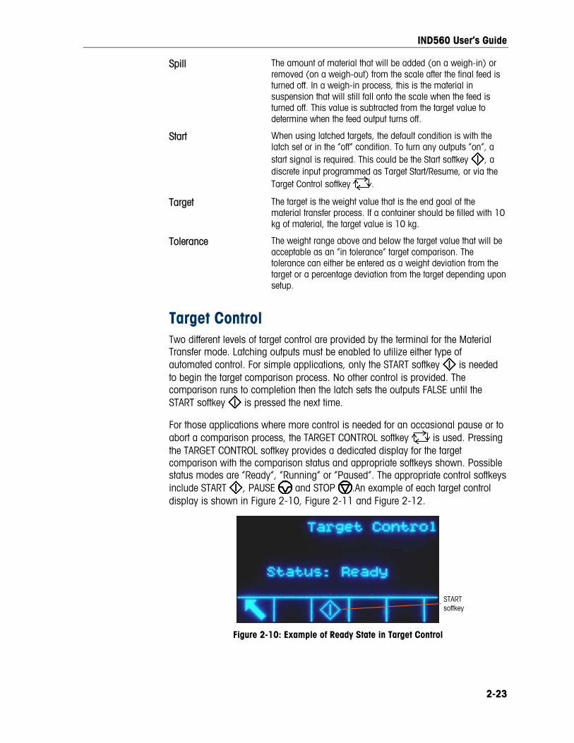
IND560 User’s Guide
Spill The amount of material that will be added (on a weigh-in) or removed (on a weigh-out) from the scale after the final feed is turned off. In a weigh-in process, this is the material in suspension that will still fall onto the scale when the feed is turned off. This value is subtracted from the target value to determine when the feed output turns off.
Start When using latched targets, the default condition is with the latch set or in the “off” condition. To turn any outputs “on”, a start signal is required. This could be the Start softkey , a discrete input programmed as Target Start/Resume, or via the Target Control softkey .
Target The target is the weight value that is the end goal of the material transfer process. If a container should be filled with 10 kg of material, the target value is 10 kg.
Tolerance The weight range above and below the target value that will be acceptable as an “in tolerance” target comparison. The tolerance can either be entered as a weight deviation from the target or a percentage deviation from the target depending upon setup.
Target Control Two different levels of target control are provided by the terminal for the Material Transfer mode. Latching outputs must be enabled to utilize either type of automated control. For simple applications, only the START softkey is needed to begin the target comparison process. No other control is provided. The comparison runs to completion then the latch sets the outputs FALSE until the START softkey is pressed the next time.
For those applications where more control is needed for an occasional pause or to abort a comparison process, the TARGET CONTROL softkey is used. Pressing the TARGET CONTROL softkey provides a dedicated display for the target comparison with the comparison status and appropriate softkeys shown. Possible status modes are “Ready”, “Running” or “Paused”. The appropriate control softkeys include START , PAUSE and STOP .An example of each target control display is shown in Figure 2-10, Figure 2-11 and Figure 2-12.
START softkey
Figure 2-10: Example of Ready State in Target Control
2-23

IND560 User’s Guide
PAUSE softkey
Figure 2-11: Example of Running State in Target Control
RESUME (START) softkey
ABORT (STOP) softkey
Figure 2-12: Example of Paused State in Target Control
Over/Under Applications If the target comparison of the IND560 will be used to checkweigh the weight of a product, the application can be classified as an Over/Under application. These types of applications are usually manual processes but can also be automated. The SmartTrac display indicates the classification of the weight placed on the scale and discrete I/O can be used to trigger external lights or other controls. The terminal compares the current weight to a previously entered target with tolerance values or to zone limits and indicates the results. The following definitions will explain some terms used in Over/Under applications. The following definitions apply to over/under applications:
Over Limit If a tolerance mode of “Weight value” is selected in setup, the IND560 does not require the entry of a target value. In this mode, only the upper and lower limits for the OK zone are entered. When programmed for this mode, the over limit value is the maximum weight that will be classified as OK. Any weight above than this value will be classified as Over.
Over/Under Mode The target comparison mode that provides three zone classifications for weight placed on the scale. The classification can be Under if the weight is below the target minus the -tolerance, OK if within the tolerance range or Over if the weight is above the target plus the +tolerance.
Target The target is the ideal weight value for the product being tested. If a container should weigh exactly 10 kg, the target value is 10 kg.
Tolerance The weight range above and below the target value that will be acceptable as “OK” in the target comparison. The tolerance can either be entered as a weight deviation from the target, a percentage deviation from the target or as absolute weight (zone
2-24

IND560 User’s Guide
edges) depending upon setup.
Under Limit If a tolerance mode of “Weight value” is selected in setup, the IND560 does not require the entry of a target value. In this mode, only the upper and lower limits for the OK zone are entered. When programmed for this mode, the under limit value is the minimum weight that will be classified as OK. Any weight below than this value will be classified as Under.
Zones The IND560 provides 3 different classifications or “zones” in the Over/Under mode. The zones are Under, OK and Over.
Target Comparison Parameter Entry To enter target comparison parameters, either directly edit the active records or load them with data from a record in the Target Table.
Direct Editing of Active Records
To directly edit the active record:
1. Press the TARGET softkey . (See Chapter 3.0, Configuration, the Terminal section, Softkeys, for information about how to setup softkey display.) The Active Values screen displays.
2. Use the UP and DOWN navigation keys to scroll through the fields available for editing.
3. Press the ENTER key to select a field to edit.
4. Depending whether the mode is material transfer or over/under, and the type of tolerance selected, the active target record will show different fields to edit. Use the navigation and numeric keys to enter values for all of the fields as needed.
Over/Under Material Transfer, Either Mode Weight Deviation or % of Target Weight Value
Target Target Over Limit
Spill + Tolerance Under Limit
Fine Feed - Tolerance
+ Tolerance
- Tolerance
5. Use the alpha keys to enter a description.
6. Press the OK softkey to accept the edits to the active record.
7. Press the ESCAPE softkey to return to the weighing operation screen without saving the active record edits.
Loading Records from the Target Table
The TARGET MEMORY softkey can be used in two ways to load records from the Target Table: Quick Access and List Selection.
2-25

IND560 User’s Guide
Quick Access to Records
Use the Quick Recall mode when the ID of the Target Table record to be loaded is known. Use the numeric keypad to enter the ID and then press the TARGET MEMORY softkey to load the record. If the record is available, the data is loaded. If the record is not found, an “ID not found” error displays.
List Selection
Use the List Selection mode when the ID of the Target Table record is unknown. To use the List Selection mode:
1. Press the TARGET MEMORY softkey without any preceding data entry. The Target Search screen displays.
2. Enter any search restrictions required or leave selections as they are to retrieve all records.
3. Press the SEARCH softkey to view the selected records in the table.
4. Use the UP and DOWN navigation keys to scroll through the list until the desired record is highlighted.
5. Press the OK softkey to load the selected record from the list.
6. Press the ESCAPE softkey to return to the weighing operation screen without loading the record.
Record Selection Using Shared Data
Alternatively, the Shared Data server can be used to activate target records stored in the Target Table. Refer to the Shared Data Access section of Appendix D, Communications, and the Shared Data Reference found on the documentation CD for specific instructions.
Target Units
If second and/or third units are established in the IND560, target records that utilize either second or third units can be retrieved from the Target Table into Active Target status. The IND560 will convert the retrieved record into active units when the record is recalled. Pressing the TARGET softkey will show the original units as recalled from the Target Table.
If an attempt is made to retrieve a record from the Target Table that does not use primary, second or third units, a “Units Mis-match” error will display indicating that record recall was unsuccessful.
Comparators Comparators are simple targets, five of which can be configured in setup. They are controlled either by coincidence or by comparison with a range. The source for comparison can be the Gross Weight, Displayed Weight, Rate or assigned by a custom TaskExpert application. When assigned to the home screen, the Comparator softkey permits direct access to the Comparators. This screen displays each Comparator’s ID, Description, Limit, Unit, High Limit (if applicable) and Active operator. Only the limit value/s can be edited. To edit parameters other than limits, the Comparator configuration screen must be accessed in setup.
2-26

IND560 User’s Guide
To access a comparator’s limit editing page directly from the home screen, press the ID number of the Comparator, then the Comparator softkey. If the ID number is not known, press the Comparator softkey , use the UP/DOWN keys to select the desired Comparator from the list, and press the Edit softkey .
When the Active value is <, <=, =, >= or >, the selected source is compared to a target weight. When the Active value is within (>_ _<) or outside (_< >_) a range, the selected source is compared to a range defined by the Limit and High Limit values.
Using Comparators To use a Comparator, it must be assigned to a discrete output.
Target Value Comparators
In this case, the output will be triggered depending on the Active setting. For example, if the Active operator is <= (less than or equal to) and the Limit is 1000 kg, the output will turn OFF when the measured value reaches 1000 kg.
Range Comparators
In the case of a Range mode Comparator, the Limit value sets the lower of the two rates that define the range, within or outside (depending on the operator) which the output is active. For example, if the Active operator is Within (>_ _<), the Limit is 3.0 kg/sec and the High Limit is 8 kg/sec, the output will be active provided the rate remains between 3 and 8 kg/sec. If the rate falls below 3 or exceeds 8 kg/sec, the output will turn OFF.
Note that the Rate value configured in setup at Scale > Rate permits weight and time units to be defined, together with the period between measurements and the number of measurements to average to generate the output value.
If the weight information in the terminal becomes invalid, the Rate display will show 0.000.
A Range Comparator can also use displayed or gross weight as its source. For example, if displayed weight (possibly a net value, allowing for the weight of a hopper) is the source, the Active operator is Outside, and the Limit and High Limit are 1000 kg and 1500 kg respectively, the output will remain active as long as the source value is below 1000 kg. In this case a large enough value for the High Limit should be set to ensure that, once the Limit is reached and the output turned off, there is not sufficient spill to reach the High Limit and reactivate the output.
ID The ID function provides a convenient and simple way to ensure that a specific sequence of operation is carried out the same way each time. Each step can include an on-screen message that instructs the operator to perform an action, or a prompt asking the operator to enter some information. These steps may include data entry (using the numeric keypad, alphanumeric keys, or some other input such as a barcode scanner) and actions (such as placing a package on the scale,
2-27

IND560 User’s Guide
taking a tare, or printing a ticket for the transaction). When a step is completed, pressing the ENTER key moves to the next one.
As many as 20 steps may be programmed, and the sequence can be triggered in one of two ways:
• Manually, using the ID softkey
• Automatically, by threshold and reset weight readings from the scale
If the sequence is triggered manually, it may be programmed to loop, repeating all steps until either the EXIT softkey is pressed, or an ESC softkey is pressed while an alphanumeric entry field is selected.
When ID mode is set to function automatically, placing on the scale a weight that exceeds a pre-configured threshold value initiates the sequence. When all the steps have been performed and the weight is removed, the reading from the scale falls below a reset value. At this point the terminal is ready to begin the next ID sequence.
For details on ID mode configuration, refer to Chapter 3.0, Configuration.
SmartTrac™ SmartTrac is a graphical display visualization of either the gross or net weight as selected in setup. SmartTrac on the IND560 uses a bar graph visualization type for Material Transfer mode and a three-zone graphic for Over/Under mode.
Material Transfer Mode The operator adds material until the measured value is within an acceptable tolerance limit. Normally an operator will add material quickly when the container is not nearly full and more slowly as the target value approaches.
The SmartTrac display may be configured in setup as Small, Medium or Large. Each size provides different target and weight information on the display. Figure 2-13 shows the small size, Figure 2-14 shows the medium size, and Figure 2-15 shows the large size.
Weight display
SmartTrac indicating weight on target
Figure 2-13: Material Transfer SmartTrac, Small
2-28

IND560 User’s Guide
Weight display
Target description SmartTrac
Target weight
Figure 2-14: Material Transfer SmartTrac, Medium
SmartTrac
Target weight
No weight display
Target description
Upper tolerance value Lower
tolerance value
Figure 2-15: Material Transfer SmartTrac, Large
While the bar graph display appears to be one continuous bar graph, it can actually be broken into four separate sections or ranges. Depending upon the target and tolerance values used, there could be one, two, or three speeds at which these graphical sections are filled in. Figure 2-16 illustrates the ranges.
Figure 2-16: SmartTrac Bar Graph Display Ranges
Under Tolerance
The Under Tolerance range is labeled “A” in Figure 2-16. This range represents the amount of material from 10% of the target value to the target minus the negative tolerance value. The bar graph begins to populate the “A” range when more than 10% of the target has been added. Until reaching the 10% point, no fill is shown.
Acceptable Under Tolerance
Region B in Figure 2-16 represents the zone of acceptable tolerance below the target value.
On Target
When the measured value exactly equals the target value an unfilled triangle indication displays (see Figure 2-17).
Figure 2-17: On-Target Triangle
2-29

IND560 User’s Guide
Acceptable Over Tolerance
Region C in Figure 2-16 represents the zone of acceptable tolerance above the target value.
Over Tolerance
Region D in Figure 2-16 represents the zone of unacceptable tolerance above the target value. In Region D, the fill rate reverts to the same rate as used in Region A. If the measured value is large enough that the number of dot columns required for display exceeds the number available, the display saturates and further increases in the measured value do not affect it.
Over/Under Mode There are three sizes of Over/Under SmartTrac selectable in setup. Each size provides different target and weight information on the display. Figure 2-18 shows the small size, Figure 2-19 shows the medium size, and Figure 2-20 shows the large size. Note that Figure 2-18 shows a composite display with under, OK and over graphics displayed simultaneously.
Weight display
SmartTrac
Figure 2-18: Over/Under Display, Small
Weight display
SmartTrac
Target description
Target weight
Figure 2-19: Over/Under Display, Medium
Target description
Upper tolerance value
Lower tolerance value
Target weight
SmartTrac
Figure 2-20: Over/Under Display, Large
2-30

IND560 User’s Guide
Less than 10% of Target
Until the weight on the scale reaches 10% of the target value, the Under symbol is
shown as a dashed line symbol or , and the discrete outputs are disabled. The Under zone symbol becomes solid and the discrete outputs become active when more than 10% of the target has been added.
Under Zone
The Under zone is shown in Figure 2-18 as the symbol to the left and also in Figure 2-19. This zone classification is shown when the weight on the scale is greater than 10% of the target but less than the target value minus the -tolerance value. If a discrete output has been assigned to the Under Zone, that output will be “on” when the weight is in this zone.
OK Zone
When the weight on the scale is between the target minus the -tolerance and the target plus the +tolerance, the OK symbol is shown. This symbol is the same symbol for all sizes of SmartTrac and shown in Figure 2-18 as the center symbol. If a discrete output has been assigned as Tolerance - OK, that output will be “on” when the weight is in this zone.
Over Zone
The Over zone is shown in Figure 2-18 as the symbol to the right and also in Figure 2-20. This zone classification is shown when the weight on the scale is greater than the target value plus the +tolerance value. If a discrete output has been assigned to the Over Zone, that output will be “on” when the weight is in this zone.
Time and Date Time and date are used for reporting, error and transaction log timestamps, and triggering service events. The TIME & DATE softkey enables access to the Set Time & Date screen where the user can set the time and date, including the hours, minutes, day, month, and year. When the time is set, seconds are set to 0.
Although the format for the time and date can be selected according to local preferences, the use of a timestamp in log files is not selectable. Timestamp formats are always fixed as:
Date: YYYY/MM/DD (for example, July 23, 2005 becomes the fixed format date 2005/07/23)
Time: HH:MM:SS stored in 24 hour format (for example, 10:01:22 PM becomes the fixed format time 22:01:22)
Reports Reports may be generated, viewed, and printed from database tables including:
• Alibi Memory
2-31

IND560 User’s Guide
• Tare Table
• Target Table
The REPORTS softkey must display on the operational screens to generate table reports. Otherwise, table reports can only be generated from within setup.
To generate a report:
1. Press the REPORTS softkey . The Reports screen (Figure 2-21) displays.
TYPE selection box
PRINT softkey
CLEAR TOTALS softkey
VIEW TABLsoftke
E y
EXIT softkey
Figure 2-21: Reports Screen
2. Use the UP and DOWN navigation keys to select the desired type of database table report in the selection box.
3. The CLEAR TOTALS softkey displays when the Tare Table is selected that has totals enabled in setup. If Clear after Print is enabled in setup for the selected table, the CLEAR TOTALS softkey does not display. Press the CLEAR TOTALS softkey to clear the totals in the selected table. A warning displays that requires verification that the user wants to clear the table totals.
4. Press the PRINT softkey on this screen to print the entire selected report.
The CLEAR TOTALS and PRINT functions are only accessible to users with a log-in level of Supervisor and above.
5. Press the EXIT softkey to return to the home screen.
6. Press the VIEW TABLE softkey to select a sub-set of records from the table. The Search Screen for the selected report type displays (see Figure 2-22).
Search Field selection box
Comparison selection box
SEARCH softkey
Figure 2-22: Search Screen (Tare Table)
7. Press the SEARCH softkey to view all data in the table. Only fields enabled in setup display in tables.
8. To limit the data:
2-32

IND560 User’s Guide
A. Use the Search Field selection box to select a desired search field (for example, search fields for the Tare table include Description, ID, n, Tare, and Total).
B. Use the Comparison selection box to select how the data will be limited (less than (<), less than or equal to (<=), equal to (=), greater than or equal to (>=), greater than (>), or not equal to (<>) are available in the selection box).
C. Use the numeric keypad to enter the limiting factor in the text box (the * character is the “wild-card” character and returns all results).
D. Press the SEARCH softkey to view the limited data in the table. Search result records are always listed in order by ID (lowest to highest ID numbers). Use the arrow keys to scroll left and right to view additional columns. Figure 2-23 is an example of search results for a Tare Table, with a series of views showing all available columns of data.
Figure 2-23: Tare Table Search Results
Calibration Test The IND560 terminal provides a programmable Calibration Test sequence that can contain up to 25 individual steps. The Calibration Test is designed to lead the tester through a set of predetermined steps and compare the terminal calibration with known test weights.
2-33

IND560 User’s Guide
The test is accessed by pressing the CALIBRATION TEST softkey on the home page. A screen displays where the name of the tester can be recorded and the serial number and capacity of each of the test weights used can be entered. This provides a traceable record for the calibration test.
The calibration test is started by pressing the START softkey . A display is shown that provides the active scale weight, the target and tolerance weight values, and two lines of instructions (as to where to place the weights). When the tester completes these instructions, he or she presses the OK softkey and the terminal compares the actual weight on the scale to the programmed target weight for this step. If the comparison passes, the test continues to the next step. If it fails, a message displays that indicates a failure. After acknowledging the error, the tester can abort the test, retest this step, or skip this step knowing that it failed.
At the end of the complete test, a print can be initiated that prints all the data of the calibration test. A full description of the calibration test can be found in Chapter 3.0, Configuration, Maintenance, Configure/View, Calibration Test.
CalFREE™ The IND560 terminal provides a method to calibrate a scale without using test weights. This is based on manual entry of capacity and performance data from the load cell or load cell platform. This method of calibration can be used for initial check-out and testing of systems or when a large structure is used as the weighing vessel and it is not possible to apply test weights to the structure. METTLER TOLEDO highly recommends that test weights be used whenever possible as this provides the most accurate method of calibration.
Alibi Memory Direct Access The Alibi Memory stores transaction data that can be retrieved in order to verify transaction information.
• The information stored in the Alibi Memory includes:
• Transaction counter value
• Date and time of transaction
Gross, net, and tare weights including units of measure
To view and print the Alibi Memory:
1. Press the Alibi softkey if programmed as one of the home position softkeys or press the REPORTS softkey if programmed as one of the home position softkeys then select Alibi Memory from the selection box.
2. Press the VIEW TABLE softkey . The Alibi Search View screen displays.
3. Use the selection boxes and data entry fields to enter specific search information to limit the search, or do not enter any search limits to view all Alibi Memory Table information.
2-34

IND560 User’s Guide
4. Press the START SEARCH softkey . The Alibi Search View screen displays the search results. Records are ordered by date and time with the most recent record shown last.
5. Press the PRINT softkey on this screen to print the entire selected Alibi Memory Table.
Table Searches A table search can be accessed using various methods, including the TARE MEMORY softkey , TARGET MEMORY softkey , ALIBI softkey , REPORTS softkey , and from the menu tree.
To search a table:
1. Access the table to be viewed using the appropriate method. Refer to Appendix C, Table and Log File Structure, for more information about how to access specific tables.
2. Press the VIEW TABLE softkey . The Search View screen displays.
3. Use the selection and data entry boxes to enter specific search information to limit the search, or enter * (the “wild-card” character) to view all table information.
4. Press the START SEARCH softkey . The Search View screen displays with the search results.
Remote Display When properly configured, the IND560 can function as a remote display for another IND560 terminal or for another Mettler Toledo terminal capable of handling Mettler Toledo Continuous Output.
If the Remote IND560 will be used to issue simple commands to another terminal (referred to as the Master terminal), the Master must be able to accept Command Inputs (CPTZ).
Figure 2-24: Example of Terminal Configuration for Remote Display Function
2-35

This chapter covers
• Entering Setup Mode
• Exiting Setup Mode
• Setup Menu Tree
• Overview of Configuration
• Configuration Options
• Restoring Factory Default Settings
Chapter 3.0 Configuration
This chapter provides information about how to configure the IND560 terminal’s operating system. It describes access to the setup mode, where functions can be enabled, disabled, or defined by entering parameter values in specific setup screens.
Entering Setup Mode The configuration of the IND560 terminal is accessed through the SETUP softkey
. If password security has been enabled, a login screen (Figure 3-1) displays and the user must enter the correct password in order to advance into setup. (See the Security section in Chapter 2.0, Operation, and the Configuration Options, Terminal, Users section of this chapter for further information about password setup and security.) To exit back to the home screen without entering any login information, press the ESCAPE softkey .
Username entry box
Password entry box
Figure 3-1: Login Screen
3-1
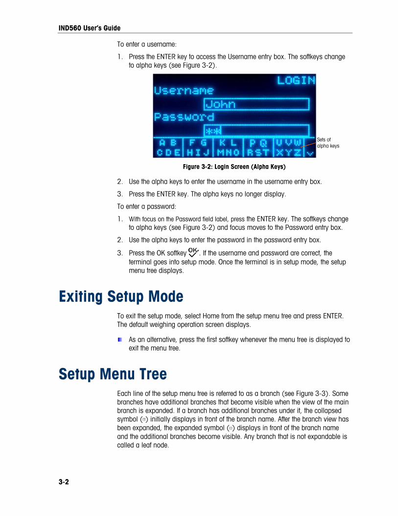
IND560 User’s Guide
To enter a username:
1. Press the ENTER key to access the Username entry box. The softkeys change to alpha keys (see Figure 3-2).
Sets of alpha keys
Figure 3-2: Login Screen (Alpha Keys)
2. Use the alpha keys to enter the username in the username entry box.
3. Press the ENTER key. The alpha keys no longer display.
To enter a password:
1. With focus on the Password field label, press the ENTER key. The softkeys change to alpha keys (see Figure 3-2) and focus moves to the Password entry box.
2. Use the alpha keys to enter the password in the password entry box.
3. Press the OK softkey . If the username and password are correct, the terminal goes into setup mode. Once the terminal is in setup mode, the setup menu tree displays.
Exiting Setup Mode To exit the setup mode, select Home from the setup menu tree and press ENTER. The default weighing operation screen displays.
As an alternative, press the first softkey whenever the menu tree is displayed to exit the menu tree.
Setup Menu Tree Each line of the setup menu tree is referred to as a branch (see Figure 3-3). Some branches have additional branches that become visible when the view of the main branch is expanded. If a branch has additional branches under it, the collapsed symbol (⊞) initially displays in front of the branch name. After the branch view has been expanded, the expanded symbol (⊟) displays in front of the branch name and the additional branches become visible. Any branch that is not expandable is called a leaf node.
3-2

IND560 User’s Guide
The first branch of the menu tree shown with focus is the Scale branch (Figure 3-3).
Figure 3-3: Setup Menu Tree Example
Use the UP and DOWN navigation keys to move focus through the branches of the setup menu tree.
Press the RIGHT navigation key to expand a branch and the LEFT navigation key to collapse a branch. When the focus is on a sub-branch, focus can quickly be moved back to the main branch by pressing the LEFT navigation key.
When a leaf node (singular, non-expandable) branch such as Device or Display is in focus, press the ENTER key to display the setup screen for that function.
Setup Screens Setup screens enable access to data fields where parameters can be viewed, entered, or modified to configure the terminal to meet specific application function needs.
Navigation Press the UP and DOWN navigation keys to move through the field labels displayed on each setup screen, and to move to a second or third setup screen when more than one screen is used for configuration fields associated with a specific parameter (indicated by the presence of a scroll bar). The shaded portion of the scroll bar (see Figure 3-4) indicates which screen is displayed.
3-3
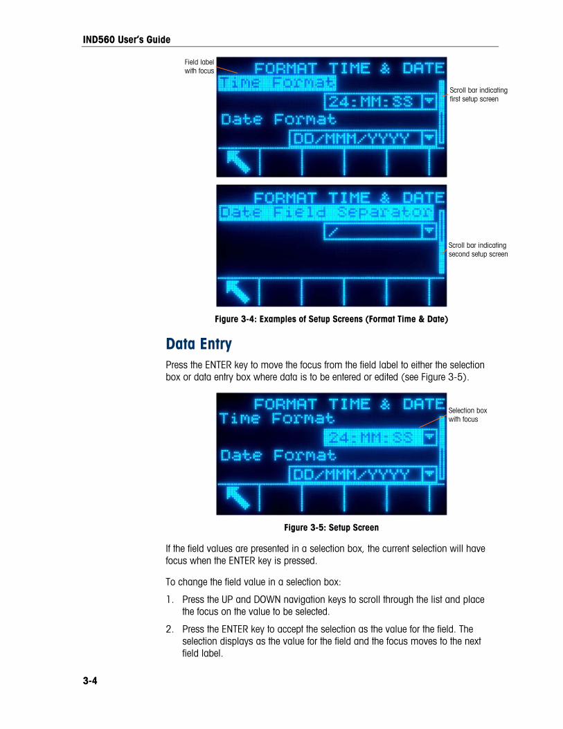
IND560 User’s Guide
Field label with focus
Scroll bar indicating first setup screen
Scroll bar indicating second setup screen
Figure 3-4: Examples of Setup Screens (Format Time & Date)
Data Entry Press the ENTER key to move the focus from the field label to either the selection box or data entry box where data is to be entered or edited (see Figure 3-5).
Selection box with focus
Figure 3-5: Setup Screen
If the field values are presented in a selection box, the current selection will have focus when the ENTER key is pressed.
To change the field value in a selection box:
1. Press the UP and DOWN navigation keys to scroll through the list and place the focus on the value to be selected.
2. Press the ENTER key to accept the selection as the value for the field. The selection displays as the value for the field and the focus moves to the next field label.
3-4

IND560 User’s Guide
If the field value is for a data entry box and alpha/numeric character entry is possible, the alpha keys will display.
To change the field value using alpha/numeric characters:
1. When a data entry box is first entered, the previous data (if present) is in focus. To replace previous data, use the alpha keys and the numeric keypad to enter the desired value.
OR
Press the LEFT and RIGHT navigation keys to move the cursor into position if the value needs to be edited from a specific point rather than replaced. Position the cursor at the end of the data to be deleted and press the C key once for each character to be deleted.
2. Press the ENTER key to accept the entered alpha/numeric characters for the field. The entry displays as the value for the field and the focus moves to the next field label.
To exit a setup screen, press the EXIT softkey , which is in the first softkey position. The setup menu tree displays with the focus on the branch for the setup screen that was exited.
Overview of Configuration The setup menu tree can be expanded to show every branch and leaf node in the terminal’s configuration. Use the navigation keys to select the desired setup screen.
There are five major branches in the setup menu:
• Scale
• Application
• Terminal
• Communication
• Maintenance
3-5

IND560 User’s Guide
Details for each branch are provided in the following Configuration Options section. Figure 3-6 shows the setup menu tree with all branches expanded.
Figure 3-6: The IND560 Menu Tree with All Branches Expanded
The TaskExpert leaf node is only available if the TaskExpert Application Software module has been installed into the IND560.
3-6

IND560 User’s Guide
Configuration Options Configure terminal options on the setup screens that are available under the five major branches of the setup menu.
If the metrology switch is in the approved position (SW1-1 = ON), access to the Scale branch is not permitted. The Scale branch will not be expandable on the setup menu tree.
Scale The Scale branch provides the following access to the configuration of the connected scales:
• Type*
• Capacity and increment values*
• Calibration*
• Zero parameters*
• Tare parameters*
• Units
• Rate parameters
• Filter parameters*
• Stability parameters*
• Log or print threshold parameters
• Minimum weight parameters
Leaf nodes that are marked with an asterisk (*) above will have different parameters depending on the connected scale type (analog or IDNet).
A Reset is present at the end of the branch to enable a limited reset to the factory default settings for the Scale branch parameters.
Type The Scale Type screen permits a name to be assigned to the scale, displays the scale PCB Type in the terminal, provides a selection list for the Approval mode, and allows the IND560 to be configured as a Remote Display for another (Master) terminal. The EXIT softkey will return the display to the menu tree.
Name
The Name field enables entry of the scale identification. Enter the scale name (an alpha-numeric string of up to 20 characters) in the Name entry box.
3-7

IND560 User’s Guide
3-8
Scale Type
The Scale Type field automatically shows the hardware configuration. This field will display either Analog or IDNet, along with Remote. If Remote is selected, the approval option will not be available.
Approval
Approval (analog load cells only) refers to the metrological (weights and measures) approval configuration for the specific scale. The Approval selection is not present for IDNet scale bases, but rather is part of the Service Mode of the base. The selection list can be set to:
• None – no approval is required
• USA
• OIML
• Canada
• Australia If an approval (USA, OIML, Canada, or Australia) is configured and the metrology security switch, SW1-1, is set to ON, access to the Scale setup parameters in the menu tree will be limited to view only.
If an approval is selected but SW1-1 is not ON, it will not be possible to leave setup, and a message will appear: Switch UNSECURED.
Remote Display When properly configured, the IND560 can function as a remote display for another IND560 terminal or for another Mettler Toledo terminal capable of handling Mettler Toledo Continuous Output. If the Remote IND560 will be used to issue simple commands to another terminal (referred to as the Master terminal), the Master must be able to accept Command Inputs (CPTZ).
Physical Connection of Master and Remote Terminals Communication for the remote display function occurs over a single serial connection. Each serial port in the IND560 can support one output and one input simultaneously, so only a single port is necessary for remote operation.
The standard COM1 port, and optional COM2 and COM3 ports, each support all three of the assignments used in the remote display function: Remote Display, Continuous Output and CTPZ Input. Communication can occur via RS-232, RS-422 or RS-485, but port parameters must be the same for the Master and Remote terminals. Serial port setup information can be found in Appendix D, Communications.

IND560 User’s Guide
Remote Terminal Settings In the terminal that will function as the Remote terminal, the Scale > Type setting must be Remote, as shown in Figure 3-7. Note that the Approval option is not available in this configuration.
Figure 3-7: Scale Type Setting for Remote Operation
In addition, at Communication > Connections, a port must be assigned to Remote Display, as shown in Figure 3-8.
Figure 3-8: Connection Configured for Remote Operation
It is recommended that prior to setting the Scale type as Remote, the Capacity and Increment size of the Remote terminal should be set to match the Master terminal. This will prevent any differences in display fonts that might negatively affect viewing.
Master Terminal Configuration The Master terminal must have a port configured to send display information to the Remote terminal. At Communication > Connections the serial port assignment must be Continuous Output. If the Remote terminal will be used to send commands to the Master terminal, then the same port must have a second connection assignment for CTPZ Input.
Figure 3-9 shows a typical Remote Display setup, with the Master terminal able to receive commands sent from the Remote IND560.
3-9

IND560 User’s Guide
Figure 3-9: Example of Terminal Configuration for Remote Display Function
Capacity and Increment When IDNet scale bases are installed, the Capacity & Increment setup screen does not display, but is part of the Service Mode of the base.
Use the Capacity and Increment setup screen to select primary units, set the number of ranges or intervals, and the blanking over capacity.
Primary Units
Set the primary units from the selection box choices, which include:
Grams (g) Pounds (lb) Tons (ton)
Kilograms (kg) Tonnes (t)
#Ranges
The number of ranges settings are available for analog load cells only. Set the number of ranges from one to three in the selection box. Specify the capacity and increment size for each range.
Blanking Over Capacity
The blanking over capacity settings are available for analog load cells only. Blanking of the display is used to indicate an over-capacity condition. Set the blank over capacity for the divisions (d) (display increments) that the terminal is permitted to go over capacity. For example, if capacity is set at 500 kg by 0.1 kg increments and the blank over capacity setting is 5 d, the terminal can display weights up to 500.5 kg. At weights over 500.5, dashed lines will display instead of a weight.
X10 Always
The X10 Always selection is available for IDNet load cells only. X10 Always locks the IDNet base into a higher resolution weight display. If the X10 Always mode is enabled, the high resolution weight data from the IDNet base displays at all times and the EXPAND BY 10 softkey (if configured to display) is inactivated.
The Primary Unit field displays only and is not selectable. The unit displayed is the unit that the IDNet scale base was calibrated in.
3-10

IND560 User’s Guide
3-11
Calibration The Calibration screen enables entry of a geo code adjustment value, the base serial number, calibration units, linearity adjustment, and analog gain jumper setting.
Geo Code
Enter the geo code for the appropriate geo adjustment value for the current geographical location. Geo codes are numbered 0–31. (See Appendix F.)
The Geo Code field does not display when the IDNet scale base is used.
Base Serial Number
Enter the scale base serial number in this field. An entry of up to 14 characters is possible.
Calibration Units
The Calibration Units setting is available for analog load cells only. Calibration units are listed in the selection box and are the same as the primary units selections, which include:
Grams (g) Tonnes (t)
Kilograms (kg) Tons (ton)
Pounds (lb)
Linearity Adjustment
The Linearity Adjustment setting is available for analog load cells only. Select the linearity adjustment from the selection box. Selections are as follows:
Disabled – Use only zero and one span point7
3 point – Use zero, midpoint, and highpoint
4 point – Use zero, lowpoint, midpoint, and highpoint
5 point – Use zero, lowpoint, midpoint, mid-highpoint, and highpoint
Analog Gain Jumper
The Analog Gain Jumper Setting is available for analog load cells only. The analog gain jumper setting on the Main PCB can be either 2 mv/V or 3 mv/V. The terminal is shipped from the factory in the 3 mv/V setting. In order for the CalFREE™ feature to operate properly, this parameter must indicate the position of the jumper on the Main board. The jumper settings are:
2 mv/V – Jumper installed on both pins 3 mv/V – Jumper removed
Calibration Softkeys
The Calibration setup screen displays softkeys that can be used for calibration procedures, including:

IND560 User’s Guide
Capture Zero
Capture Span
Step Calibration
CalFREE
Service Mode (IDNet scales)
Capture Zero
The Capture Zero function in the Calibration setup is available for analog load cells only. The CAPTURE ZERO softkey triggers an independent operation to reset the zero condition of the scale. A status message displays when this softkey is pressed that directs the user to empty the scale and press the START softkey . The status of the capture zero operation displays. When the operation is complete, a final status message displays that verifies the completion of the capture zero operation.
If motion is present during the zero capture process, the terminal will average the weight readings then display an error message indicating unstable weight values were used. This message must be acknowledged to save the these values.
Capture Span
The Capture Span function in the Calibration setup is available for analog load cells only. The CAPTURE SPAN softkey initiates a sequence to capture span that can be performed independently of capturing zero.
To capture span:
1. Press the CAPTURE SPAN softkey . The Capture Span setup screen displays.
2. Enter the weight for test load 1 and all other test loads if linearity has been enabled. Press the ENTER key.
3. Place test load weight 1 on the scale.
4. Press the START softkey . The status of the weight capture operation displays. When the operation is complete, a status message displays that verifies the completion of the weight capture.
Press the ESCAPE softkey to abort the calibration process and return the display to the previous screen.
5. After the first calibration step has completed, the menu will either display a prompt for the next calibration weight to be added (if 2, 3, or 4 test load steps are enabled by the linearity adjustment parameter) or will show a successful or failed calibration sequence.
If motion is present during the span capture process, the terminal will average the weight readings then display an error message indicating unstable weight
3-12
IND560 User’s Guide
values were used. This message must be acknowledged to save the these values.
6. Repeat steps 3–4 for test loads 2, 3, and 4 if enabled by linearity adjustment.
7. If the capture span operation was successful, a verification message that reads “Capture Span OK” displays If the capture span operation was not successful, an error message that reads “Calibration Failure” displays. If the calibration fails, repeat the capture span procedures. If the calibration continues to fail, contact a local METTLER TOLEDO representative for assistance.
8. Press the EXIT softkey to return to the Calibration screen.
Step Calibration
The Step Calibration function in the Calibration setup is available for analog load cells only. The STEP CALIBRATION softkey initiates a procedure that enables a “build-up” calibration for tanks and hoppers. For step calibration, the same amount of test weight is added for each step of the calibration procedure.
To perform a step calibration:
1. Press the STEP CALIBRATION softkey . The Step Calibration setup screen displays.
2. Enter the target weight for the test load (the same amount of test load weight is used in each step).
3. Press the START softkey . The Step Calibration screen displays. This screen shows an active (live) weight display (using the current span factor), the intended target weight as entered on the previous screen, and the next step for the operator “Add test weight.”
4. Add test weight to the tank/hopper as prompted by the display. Each time test weight is added to the scale, the active display shows the weight.
5. When the full amount of test weight has been added, press the OK softkey . The test load is captured and span factors are saved. During the time the weight is captured and the new span factor is being calculated, the display “Add test weight” changes to “Capturing span.” The display then changes to the next prompt “Remove test weight then fill to target.”
6. Remove the test weight. The active display returns to zero.
7. Fill the tank/hopper with a substitute material up to the target weight.
8. Press the OK softkey . The target weight value recalculates to show the substitute material weight plus the initial intended target weight. The display changes to the next prompt “Add test weight.”
9. Add test weight to the tank/hopper. The active display shows the weight.
10. Press the OK softkey . If the actual weight does not equal the target, a new span factor calculates and the display changes to “Capturing span.” The active weight display changes to match the target weight value. The display changes to the next prompt “Remove test weight then fill to target.”
11. Remove the test weight. The active display returns to the previous weight that displayed for the last test load.
3-13

IND560 User’s Guide
12. Repeat steps 7 through 11 until an appropriate number of calibration steps have been completed for the specific application.
13. Press the EXIT softkey at any step in the procedure to stop the step calibration process and return to the Calibration screen.
CalFREE
The CalFREE procedure is applicable for analog load cells only. The CALFREE softkey provides access to the span calculation screen for precalibration of a scale without test weights. High-precision scale bases are precalibrated when received from the factory so this feature is not used.
To perform precalibration of span using CalFREE:
1. Press the CALFREE softkey . The CalFREE screen displays.
2. Enter the load cell capacity and rated load cell output values in the associated fields:
The total load cell capacity should be entered here. For example, for a tank with three 5000 kg cells, cell capacity would be 3 x 5000 kg or 15000 kg.
If multiple load cells are used, the average output of all cells should be entered here.
3. Enter an estimated preload value in the associated field. Estimated preload is an optional entry. During calculation, the terminal also tests for analog/digital (A/D) converter input saturation at full scale capacity. Estimated preload is included in this calculation if entered in this field. If the preload is unknown, leave this field blank.
This preload value is used only to determine overload conditions and is not used as a zero reference point. The zero reference point must be captured using the normal zero calibration procedure.
4. Press the OK softkey . The span is calculated using the parameters entered.
5. If the calibration operation was successful, a verification message that reads “Calibration OK” displays If the calibration operation was not successful, an error message that reads “Calibration Failure” displays. If the precalibration fails, repeat the CalFREE procedures. If the precalibration continues to fail, contact a local METTLER TOLEDO representative for assistance.
6. Press the ESCAPE softkey to return to the Calibration screen.
Service Mode
Service Mode is available for IDNet load cells only. This screen displays a single box that shows messages from the IDNet base up to 16 characters. When either the (Yes) or (No) softkey is pressed, the terminal sends the respective response to the scale base and the next message to be displayed is transmitted back to the terminal from the base. This sequence remains constant during the complete service mode communication sequence. Refer to the service mode flow chart for the IDNet base used to view the exact sequence.
3-14

IND560 User’s Guide
After the last communication from the scale base has been completed, the display returns to the Scale Type screen.
Analog Saturation Test During the calibration process, the IND560 will determine if there is a potential for analog section saturation. The IND560 will compare the available number of counts with the captured span to confirm that the desired capacity is achievable. If the potential exists to saturate the analog section before system capacity is reached, the IND560 will display a warning message and recommendation that the system be recalibrated with a new, lower, capacity.
Figure 3-10: Analog Saturation Warning
This message functions only as a recommendation to recalibrate. After the warning message is acknowledged by pressing the ENTER key, the user is presented with the “Capture Span OK” screen and the BACK softkey. Service personnel should then carry out the following:
• Confirm that the analog gain jumper on the main board is set correctly for the actual load cell output, either 2mV/V or 3mV/V (refer to Appendix A, Installation, for jumper positions).
• If the analog gain jumper is correctly set, the scale should be recalibrated with a lower capacity. Potential analog section saturation does not force a failure in calibration.
IMPORTANT: It is critical that service personnel follow the recommendation to recalibrate or confirm that the analog output jumper is properly positioned on the main board. Analog section saturation will result in a ‘freeze’ of the display, where the display is no longer showing increases in weight, creating the possibility of overfills and spills during the weighing process.
Zero This section provides access to Auto Zero Maintenance (AZM) settings, under zero blanking, power-up zero, and pushbutton zero parameters.
AZM & Display
AZM is a means of tracking zero when the scale is empty. AZM compensates for conditions such as terminal or load cell drift or debris on a scale platform.
3-15

IND560 User’s Guide
3-16
Auto Zero
Use the AZM & Display setup screen to enable auto zero for gross weighing or gross and net weighing, or to turn auto zero off.
Auto Zero Range
Analog load cells: Set the auto zero range for the number of divisions (d) around the current zero setting in which auto zero will operate.
IDNet load cells: Either enable or disable the auto zero function.
Under Zero Blanking
The Under Zero Blanking function in the Zero setup is available for analog load cells only. Blanking of the display is used to indicate an under-zero condition when the weight on the scale falls below the current zero reference. Set the under zero blanking for the number of divisions (d) that the terminal is permitted to go under zero before blanking.
A value of 99 disables blanking under zero and the terminal will display a weight as far under zero as possible.
Power Up
A Power Up setting of Restart enables the terminal to save and reuse the last zero reference weight after a power cycle so it returns to the same gross weight value. If reset is selected, the last zero calibration value will be used as the zero reference point. Select either Reset or Restart from the Power Up selection box.
Ranges
Use the settings on the Ranges screen to enable or disable Power Up Zero and Pushbutton Zero and to set the ranges around the original zero condition for the scale for applying these functions.
Power Up Zero
The Power Up Zero function in the Zero setup is available for analog load cells only. If Power Up Zero is enabled, the terminal tries to capture zero upon power up.
Range
The Range setting for Power Up Zero is available for analog load cells only. If Power Up Zero is enabled, –Range and +Range fields will display for setting the range around the original zero condition for the scale within which Power Up Zero can be applied. The range units are percent.
For example, if the +Range setting for Power Up Zero is set at 2%, Power Up Zero will only occur when the weight reading on the scale is at or below 2% of the original zero condition. If the –Range setting for pushbutton zero is set at 2%, Power Up Zero will only occur when the weight reading on the scale is at or above –2% of the original zero condition.
If Power Up Zero capture is enabled and the weight on the scale is outside of the zero capture range, the display will indicate EEE until the weight is removed and zero is captured.

IND560 User’s Guide
Pushbutton Zero
If Pushbutton Zero is enabled, the front panel ZERO pushbutton will operate to capture zero reference points.
If Pushbutton Zero is Disabled, execution of a remote Zero is still possible via SICS, CPTZ, or SMA commands from a PC, Discrete Inputs or from the PLC commands.
Range
The Range setting for Pushbutton Zero is available for analog load cells only. If Power If Pushbutton Zero is enabled, –Range and +Range fields will display for setting the range around the original zero condition for the scale within which Pushbutton Zero can be applied. The range units are percent.
For example, if the +Range setting for Pushbutton Zero is set at 2%, the Pushbutton Zero can only be used when the weight reading on the scale is at or below 2% of the original zero condition. If the –Range setting for Pushbutton Zero is set at 2%, the Pushbutton Zero can only be used when the weight reading on the scale is at or above –2% of the original zero condition.
Tare Tare is used to subtract the weight of an empty container from the gross weight on the scale to determine the net weight of the contents. Tare is inhibited if the scale is in motion.
Three setup screens are available to configure tare:
Tare Types Auto Tare Auto Clear
Tare Types
Use the Tare Types setup screen to enable or disable pushbutton tare, keyboard tare, net sign correction, terminal tare (IDNet load cells only).
Pushbutton Tare
When pushbutton tare is enabled, the TARE scale function key can be pressed when an empty container is on the scale to determine tare. The terminal displays a zero weight and net mode. When the container is loaded and placed back on the scale, the terminal displays the net weight of the contents.
If Pushbutton Tare is Disabled, execution of a remote Tare is still possible via SICS, CPTZ, or SMA commands from a PC, Discrete Inputs or from the PLC commands.
Keyboard Tare
When keyboard tare is enabled, the known value for the empty weight of a container (tare) can be entered manually. The terminal will then display the net weight of the contents of the container. Keyboard tares are automatically rounded to the closest display division.
3-17

IND560 User’s Guide
3-18
Net Sign Correction
Net sign correction enables the IND560 terminal to be used for both shipping (inbound empty) and receiving (inbound loaded) operations. If net sign correction is enabled, the terminal will switch the gross and tare weight fields on the printed ticket, if necessary, so that the larger weight is the gross weight, the smaller weight is the tare weight, and the difference is always a positive net weight. Net sign correction affects the printed data output, the recalled weigh display and the displayed weight. Continuous data output will continue to show a negative net weight value.
Net sign correction will operate with pushbutton tare, preset tare, or tare memories. An example of weight values with and without net sign correction is shown in Table 3-1. In this example, the tare register value is 53 kg and the live weight on the scale is 16 kg.
Table 3-1: Weight Values With and Without Net Sign Correction
Net Sign Correction
Printed and Displayed Disabled Enabled
Gross 16 kg 53 kg
Tare 53 kg 16 kg
Net −37 kg 37 kg
When net sign correction is enabled, the tare weight field in the recall display will be labeled with the letter “M” to indicate “Memory” instead of “T” or “PT”.
Terminal Tare
The Terminal Tare field only displays when an IDNet scale base is present. When terminal tare is enabled, tare and net weight values are calculated in the terminal and not in the high precision IDNet base. Terminal Tare should be disabled for approved (legal-for-trade) systems.
Auto Tare
Use the Auto Tare screen to enable or disable automatic tare and to set the tare and reset threshold weights, and enable or disable motion check.
Auto Tare
When auto tare is enabled, the tare weight is taken automatically when a container above the threshold weight is on the scale and settles to no-motion.
Tare Threshold Wt.
When weight on the scale platform exceeds the tare threshold value and settles to no-motion, the terminal automatically tares.
Reset Threshold Weight
The reset threshold weight must be less than the tare threshold weight. When the weight on the scale platform falls below the reset threshold value, such as when a

IND560 User’s Guide
3-19
load has been removed, the terminal automatically resets the auto tare trigger, depending upon the programming of motion checking.
Motion Check
Enable the motion check setting to prevent auto tare reset rigger from occurring when the scale is in motion. When enabled, the scale must detect a non-motion condition below the reset value to reset the trigger.
Auto Clear
Use the Auto Clear screen to enable or disable auto clear tare, clear after print, to set the clear threshold weight, and enable or disable motion checking for auto clearing of tare.
Auto Clear Tare
To clear tare automatically when the scale returns to below the threshold weight, enable the auto clear tare setting.
Clear Threshold Wt.
When the gross scale weight exceeds then falls below the clear threshold weight value, the terminal automatically clears tare and returns to gross mode.
Motion Check
The Motion Check field displays only when Auto Clear Tare is enabled. Enable the motion check setting to prevent auto clear from occurring when the scale is in motion.
Clear After Print
The Clear After Print field displays only when Auto Clear Tare is enabled. To clear tare automatically after printing, enable the clear after print setting.
Clear With Zero
To clear tare automatically when capturing zero, enable the clear with zero setting.
Power Up
A Power Up setting of Restart enables the terminal to save and reuse the last tare weight after a power cycle. If Reset is selected, the terminal returns to gross mode upon power up and the last tare weight after the power cycle is cleared. Select either Restart or Reset from the Power Up selection box.
Units This setup screen enables the selection of a second and a third unit and power up units.
Second Unit and Third Unit
Use the Second Unit and Third Unit selection boxes to select second and third weighing units, configure custom second and third units, or to select none. Only one custom unit is possible.

IND560 User’s Guide
3-20
If printing of two units is required, establish Third Units. Both Primary and Third units can be printed simultaneously in an output template.
Available weighing units include:
Custom Pounds-Ounces (lb-oz)
Pennyweight (dwt) Ounces (oz)
Grams (g) Troy Ounces (ozt)
Kilograms (kg) Tonnes (t)
Pounds (lb) Tons (ton)
Power Up
Power up units defines the units the terminal defaults to after power up. Use the selection box to select either Primary Units or Restart, which makes the power up units those that were active when power was removed.
Custom Units
If Custom is selected for second or third units, three additional fields display for configuring custom units. The terminal displays the first three letters of the custom name in the units area of the display when custom units are in use.
Custom Factor
Enter a multiplication factor for the custom unit in this field, such as 0.592 or 1.019. The primary unit is multiplied by the custom factor to obtain the custom value.
Custom Name
The softkeys turn into alpha keys when this field is selected. Use the alpha keys to enter the name for the custom unit. Up to 12 characters may be entered.
Custom Increment
Enter a custom increment in this field, such as 0.1 or 0.5. This step controls both the decimal position and the increment size of the custom unit value.
Rate A Rate, expressed as change in primary or secondary weight units per time unit, may be programmed for display on the IND560 (Figure 3-11) and/or used in controlling discrete outputs – for example as the source for a Comparator (described later in this chapter).
The Rate display is over-ridden by SmartTrac. If SmartTrac is enabled, the Rate display option is not available in the Terminal > Display screen.
If the weight information in the terminal becomes invalid, the Rate display will show 0.000.
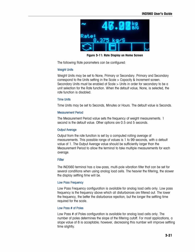
IND560 User’s Guide
Figure 3-11: Rate Display on Home Screen
The following Rate parameters can be configured:
Weight Units
Weight Units may be set to None, Primary or Secondary. Primary and Secondary correspond to the Units setting in the Scale > Capacity & Increment screen. Secondary Units must be enabled at Scale > Units in order for secondary to be a unit selection for the Rate function. When the default value, None, is selected, the rate function is disabled.
Time Units
Time Units may be set to Seconds, Minutes or Hours. The default value is Seconds.
Measurement Period
The Measurement Period value sets the frequency of weight measurements. 1 second is the default value. Other options are 0.5 and 5 seconds.
Output Average
Output from the rate function is set by a computed rolling average of measurements. This possible range of values is 1 to 99 seconds, with a default value of 1. The Output Average value should be sufficiently larger than the Measurement Period to allow the terminal to take multiple measurements for each average.
Filter
The IND560 terminal has a low-pass, multi-pole vibration filter that can be set for several conditions when using analog load cells. The heavier the filtering, the slower the display settling time will be.
Low Pass Frequency
Low Pass Frequency configuration is available for analog load cells only. Low pass frequency is the frequency above which all disturbances are filtered out. The lower the frequency, the better the disturbance rejection, but the longer the settling time required for the scale.
Low Pass # of Poles
Low Pass # of Poles configuration is available for analog load cells only. The number of poles determines the slope of the filtering cutoff. For most applications, a slope value of 8 is acceptable; however, decreasing this number will improve settling time slightly.
3-21

IND560 User’s Guide
3-22
Notch Filter Frequency
Notch Filter Frequency configuration is available for analog load cells only. The notch filter allows selection of one specific frequency below the low pass filter value that can also be filtered out. This enables setting the low pass filter higher to filter out all but one frequency (that the notch filter will handle) and obtain a faster settling time. Values from 0 (disable) to 99 are possible.
Stability Filter
Stability Filter configuration is available for analog load cells only. The stability filter works in conjunction with the standard low pass filter to provide a more stable final weight reading. The stability filter should only be used in transaction weighing applications, since the nonlinear action of the filter switching may cause inaccurate cutoffs in batching or filling applications. The stability filter can be enabled or disabled on this setup screen.
IDNet Filtering
Configuration for IDNet filtering parameters is performed on the Filter screen. Use the Vibration selection box to select a condition setting that reflects the specific location’s conditions. Selections include:
Ideal Conditions The weighing platform operates very quickly. However, it is very sensitive. This setting is suitable for a very calm and stable weighing location.
Average Conditions This is the factory default setting and is suitable for most normal environments.
Extreme Conditions The base reacts to changes in weight more slowly but is much more stable in unstable environments.
Use the Weighing Process selection box to select the specific weighing process in use. Selections include:
Fine Filling Used when liquid or fine powders are being weighed
Universal Weighing For solid materials coarse filling or checkweighing
Static Weighing For solid materials and weighing under extreme conditions such as strong vibrations
Dynamic Weighing For weighing products that will not be fully stable or still during the weighing process
Stability The IND560 terminal includes a stability detector (weight in motion). For analog load cells, the Stability setup screen enables setting a motion range, no-motion interval and timeout period. For IDNet bases, a stability measure and timeout period may be set.

IND560 User’s Guide
3-23
Analog Load Cell Stability
Motion Range
Sets the motion range to the weight value (in divisions) that the weight is permitted to fluctuate and still have a no-motion condition. Values from 0.1 to 99.9 are possible with the default value being 1.0.
No-motion Interval
The no motion interval defines the amount of time (seconds) that the scale weight must be within the motion range to have a no-motion condition. Values from 0.0 (motion detection disabled) to 2.0 are possible, the default value being 0.3 seconds. A shorter interval means that a no-motion condition is more likely, but may make weight measurement less precise.
Timeout
Defines the period (in seconds) after which the terminal stops attempting to perform a function that requires a no-motion condition (such as a zero, tare or print command) and aborts the function. This timeout is used regardless of the source of the command such as the keypad, discrete input, PLC or SICS. Values from 0 to 99 are possible, the default value being 3. A smaller value means that less time will be used to check for no-motion before aborting a command. When a value of 0 is entered, there must be no motion when a command is given or it will fail immediately. A value of 99 is a special condition which permits the terminal to wait indefinitely for a no-motion condition - a command would never be aborted.
IDNet Stability
Stability
Stability settings for IDNet load cells are configured by selecting a number setting of 0 (disabled), 1 (fast display, good repeatability), 2 (slower display, better repeatability), 3 (slower display, better repeatability), or 4 (very slow display, very good repeatability) in the Stability selection box.
Timeout
Defines the period (in seconds) after which the terminal stops attempting to perform a function that requires a no-motion condition (such as zero or tare) and aborts the function. This timeout is used regardless of the source of the command such as the keypad, discrete input, PLC or SICS. Values from 0 to 99 are possible with the default value being 3. A smaller value means that less time will be used to check for no-motion before aborting a command. When a value of 0 is entered, there must be no-motion when a command is given or it will fail immediately. A value of 99 is a special condition which permits the terminal to wait indefinitely for a no-motion condition - a command would never be aborted.
Log or Print
The Log or Print setup branch is where the thresholds to control how and when data is saved or output to a printer are defined. Normal demand mode printing occurs whenever a print request is made, providing there is no motion on the scale and zero has been captured (a negative gross weight will not be printed).

IND560 User’s Guide
The weight values entered are the gross weight values in primary units. Gross weight in primary units is used regardless of whether the IND560 is in Gross or Net mode and regardless of the units that are displayed.
Minimum Weight
The minimum weight setting is the threshold below which log or print functions will not initiate. Primary units are displayed for this field.
Interlock
Interlock prevents repeat logging and printing. If enabled, interlock requires that the weight reading be reset per the Reset on parameter setting (see below) and then settle to a weight greater than the minimum print value before responding to the next log or print request.
Automatic
Enable the automatic setting to log data and send a print request every time the weight on the scale settles to a positive value that is larger than the entered threshold weight value.
If Automatic is set to Disable, the Threshold Weight field does not appear.
Reset on
The resetting of auto printing or logging can be based on weight threshold or weight deviation values. Select Return (the weight must return to below this value to reset) or Deviation (the weight must change more than this value to reset) from the selection box and enter the weight value in the “Reset on” field.
If both Interlock and Automatic settings are disabled, the Reset on field does not display.
If Reset On is set to Deviation, The Threshold Weight and Motion Check fields do not display.
Threshold Weight
The Threshold Weight is the value above which an Automatic logging or printing of data can/will occur. Threshold Weight does not appear if Automatic is set to Disabled or if Reset On is set to Deviation.
Motion Check
Enable the motion check setting to prevent interlock and automatic log and print functions from resetting when the scale is in motion below the “Reset On” return point. Motion Check does not appear if Reset ON is set to Deviation.
MinWeigh
Enable the MinWeigh function to compare the current net weight with a MinWeigh value. If the net weight is greater than or equal to the MinWeigh value, all terminal functions behave normally. If the absolute value of the net weight is less than MinWeigh, the weight display includes a flashing MinWeigh symbol to the left of the weight. If the user attempts to record the weight while in this condition, the printout will include an asterisk (∗).
3-24

IND560 User’s Guide
Entry Method
The MinWeigh value entry method can be either calculated by the IND560 or directly entered.
Calculated
MinWeigh is composed of 4 factors, each determined independently:
U0 × SF × 100% MinWeigh =
T – (c × SF × 100%) Where:
U0 = Uncertainty in measurement as the applied load approaches 0. U0 is computed differently in each country and is entered in Primary units of measure.
T = Tolerance in percent, which reflects the tolerances required for the specific process and facility. The range is 0.1%–99.9%.
SF = Safety factor, which is another adjustment means. Usually SF = 1. The integer value range is 1–10.
c = Uncertainty factor related to the portion of uncertainty in measurement that is proportional to the applied load. For reference only, c = (UMAX – U0) / Max, where Max = maximum weighment and UMAX = measurement uncertainty at maximum weight.
When Calculated is selected, the user is prompted to enter the uncertainty U0, c factor, tolerance percent, and safety factor in data entry boxes. The new MinWeigh value is then computed by the weighing equipment.
Direct
For direct entry of a MinWeigh value, user enters the desired value for MinWeigh directly in the MinWeigh data entry box. The MinWeigh value is entered in Primary units of measure.
Reset
The Reset screen enables the Scale branch setup values to be reset to factory default settings.
Scale Reset
To initiate a reset, press the OK softkey . If the reset was successful, a verification message that reads “Reset Successful” displays If the reset was not successful, an error message that reads “Reset Failure” displays. If the reset fails, try to initiate the reset again. If the reset continues to fail, contact a local METTLER TOLEDO representative for assistance.
Press the ESCAPE softkey to exit without resetting.
Scale reset does NOT include the reset of metrologically significant parameters – scale type, approval, weight units, capacity, increment, or calibration data.
3-25

IND560 User’s Guide
This data is reset only by performing a Master Reset with both switches 2-1 and 2-2 in their ON positions.
Application Use application setup screens to configure:
• Memory and tables
• Operation of targets, totalization and the ID function
• Discrete I/O
Memory Memory setup screens include:
• Alibi
• Tare Table
• Message Table
• Target Table
Alibi
The Alibi Memory can be enabled or disabled in the selection box. Alibi memory is configured as a “ring” buffer that overwrites the oldest record when it reaches its memory limit. Alibi memory can hold approximately 60,000 transactions before it reaches its limit and begins overwriting old transactions. More detailed information about Alibi memory can be found in Chapter 2.0, Operation, and in Appendix C, Table and Log File Structure.
The Alibi Memory table stores basic transaction information that is not user-definable. This information always includes:
• Date and time stamp
• Transaction counter value
• Gross, tare, and net weights and weight unit If the IND560 terminal has been programmed as “approved”, Alibi Memory
enabling or disabling is only accessible if the security switch (SW1-1) is in the OFF position.
Tare Table
The Tare Table displays stored tare records, including:
• Tare record ID
• Tare weight value and unit
• Description
• Total number of transactions using each stored tare record
• Total (accumulation of tare weights for each stored tare record)
3-26
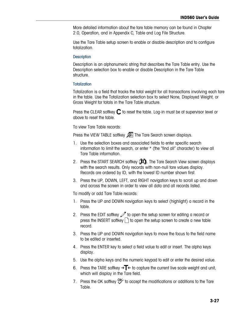
IND560 User’s Guide
More detailed information about the tare table memory can be found in Chapter 2.0, Operation, and in Appendix C, Table and Log File Structure.
Use the Tare Table setup screen to enable or disable description and to configure totalization.
Description
Description is an alphanumeric string that describes the Tare Table entry. Use the Description selection box to enable or disable Description in the Tare Table structure.
Totalization
Totalization is a field that tracks the total weight for all transactions involving each tare in the table. Use the Totalization selection box to select None, Displayed Weight, or Gross Weight for totals in the Tare Table structure.
Press the CLEAR softkey to reset the table. Log-in must be at supervisor level or above to reset the table.
To view Tare Table records:
Press the VIEW TABLE softkey The Tare Search screen displays.
1. Use the selection boxes and associated fields to enter specific search information to limit the search, or enter * (the “find all” character) to view all Tare Table information.
2. Press the START SEARCH softkey . The Tare Search View screen displays with the search results. Only records with non-null tare values display. Records are ordered by ID, with the lowest ID number shown first.
3. Press the UP, DOWN, LEFT, and RIGHT navigation keys to scroll up and down and across the screen in order to view all data and all records listed.
To modify or add Tare Table records:
1. Press the UP and DOWN navigation keys to select (highlight) a record in the table.
2. Press the EDIT softkey to open the setup screen for editing a record or press the INSERT softkey to open the setup screen to create a new table record.
3. Press the UP and DOWN navigation keys to move the focus to the field name to be edited or inserted.
4. Press the ENTER key to select a field value to edit or insert. The alpha keys display.
5. Use the alpha keys and the numeric keypad to edit or enter the desired value.
6. Press the TARE softkey to capture the current live scale weight and unit, which will display in the Tare field.
7. Press the OK softkey to accept the modifications or additions to the Tare Table.
3-27

IND560 User’s Guide
8. Press the ESCAPE softkey to return to the Tare Search View screen without saving modifications or additions.
9. Press the DELETE softkey to delete a tare record in the list.
10. Press the PRINT softkey to print the list. Login must be at supervisor level or above to print the table.
11. Press the EXIT softkey to return to the Tare Search Screen.
Message Table
The Message Table displays stored text messages and corresponding ID numbers that can be used to print templates. Only message records with non-null values display.
Press the CLEAR softkey to clear the entire table. Login must be at supervisor level or above to clear the table.
To view Message Table records:
1. Use the selection boxes and associated fields to enter specific search information to limit the search, or do not enter any search limits to view all Message Table information.
2. Press the START SEARCH softkey . The Message Search View screen displays with the search results. Records are ordered by ID, with the lowest ID number shown first.
3. Press the UP and DOWN navigation keys to scroll up and down the screen in order to view all data and all records listed.
4. Modify or add Message Table information by editing, inserting, or deleting information as described previously under Tare Table.
5. Press the PRINT softkey to print the list.
6. Press the EXIT softkey to return to the Search Screen.
Target Table
Target comparison can be used in two types of applications: material transfer and over/under. Material transfer applications require that a control device deactivate when a target value is achieved. Over/Under applications classify a load placed on the scale platform as above or below the target value.
Values in the active record registers such as the target weight and tolerance, which can be manually modified or loaded from the Target Table, are compared with either the displayed or gross scale weight.
Use the Target Table setup screen to select the mode, tolerance type, and output type for use in target comparison.
More detailed information about the target table can be found in Chapter 2.0, Operation, and in Appendix C, Table and Log File Structure.
3-28
IND560 User’s Guide
Mode
Use the Mode selection box to select the type of application for target comparison. Selections include:
• None
• Material Transfer
• Over/Under
Tolerance Type
Use the Tolerance Type selection box to select the type of tolerance to be used for target comparison. Positive tolerance and negative tolerance values can be entered as a deviation weight value in the same units as the target (Target Deviation) or as a percent of the target value (% of Target).
When over/under mode is selected, a weight value choice is available as a tolerance type. In this mode, there is no target value used – only under limit and over limit values are used as zone edges for OK.
Output Type
The Output Type field is available only when the Material Transfer mode is selected. Use the Output Type selection box to select the type of two-speed output to be used in the target application. Selections include:
Concurrent Both outputs operate at the same time
Independent One output operates at a time (Fast Feed then Feed)
Press the CLEAR softkey to reset the entire target table. Log-in must be at supervisor level or above to clear the table.
To view Target Table records:
1. Press the VIEW TABLE softkey The Target Search screen displays.
2. Use the selection boxes and associated fields to enter specific search information to limit the search, or do not enter any search limits to view all Target Table records.
Search fields that display in the Search Field selection box vary depending on the selections made on the Target Table setup screen.
3. Press the START SEARCH softkey . The Target Search View screen displays with the search results. Only records with non-null values display. Records are ordered by ID, with the lowest ID number shown first.
4. Press the UP, DOWN, LEFT, and RIGHT navigation keys to scroll up and down and across the screen in order to view all data and all records listed.
5. Target Table records include different information, depending on the selections made on the Target Table setup screen. For example, Over Limit and Under Limit data displays only when the Over/Under mode is selected with Weight Value tolerance type.
3-29

IND560 User’s Guide
Target Table records can include the following fields:
ID Identification number for the active record
Description Descriptive identification for the active record
Target The desired measured value for a weighment
Target Units The units of measure for the target weight (the target record units and the comparison units can be a combination of primary, second or third units)
Spill The amount of material delivered after the control device is signaled to stop
Positive Tolerance The highest acceptable tolerance above a target value
Negative Tolerance The lowest acceptable tolerance below a target value
Fine Feed Value For two-speed applications, the fine feed value determines when the Fast Feed output turns off.
Modify or add Target Table information by editing, inserting, or deleting information as described previously under Tare Table.
Press the PRINT softkey to print the list. Login must be at supervisor level or above to print the table.
Press the EXIT softkey to return to the Search Screen.
Operation Operation setup screens include:
• Target
• Comparators
• Totalization
• ID
Target
Use this setup screen to select which live measurement data stream (source) to use as input for target comparison and to enable or disable latching.
Source
Select which source to use as input for target comparison, either Displayed Weight or Gross Weight.
Motion Check
This parameter is shown only if target mode is set to Over/Under (at Application > Memory > Target Table). The default value is disabled. If Motion Check is enabled, the discrete outputs for Over, Under and OK are only activated when a no-motion condition is detected.
3-30

IND560 User’s Guide
Latching
If the Target Table mode selection is Material Transfer, output latching can be selected. When output latching is enabled, the target comparison outputs remain latched (OFF) after the output switching threshold is exceeded until the latch is reset by a start input (softkey or discrete input).
If latching is disabled, the outputs will operate as coincidence-type outputs with no interlocks.
Comparators
The Comparators screen permits the configuration of simple targets controlled either by coincidence or by comparison with a range, and used as an assignment for Discrete I/O outputs. Comparators are controlled either by coincidence or by comparison with a target or range. The source for comparison can be the Gross Weight, Displayed Weight, Rate or assigned by a custom TaskExpert application.
Home Screen Comparators Softkey
The Comparator softkey can be assigned to the weight display home screen. It opens the Comparators view screen, which displays the ID, Description, Limit, Unit, High Limit and Active values for each Comparator. An EDIT softkey opens a screen that display’s the selected Comparator’s Description, and permits its Limit and High Limit values to be modified. Changes can be saved ( ) or discarded ( ) when returning to the Comparators view screen.
Comparators Configuration Screen
Source, Active, Description and Limit values can only be set from the Application > Operation > Comparators screen. This screen displays all five Comparators, and contains columns for ID, Description, Source, Limit, Unit, High Limit, and Active condition. From here, it is possible to EDIT a Comparator, delete one , or clear all Comparators.
Once parameters have been set in the Comparator Edit screen, they can be saved by pressing OK , or discarded by pressing ESCAPE . In either case, the view returns to the Comparators screen.
Source
The default value for Source is None, meaning that the comparator is disabled, and no other parameter fields are displayed. Other choices for the Source are Displayed Weight, Gross Weight, Rate and Application. If a weight field is selected as the Source, the weight unit will be primary units. If Rate is selected as the Source, then the unit will be the same as selected for Rate in the Scale > Rate branch. If Application is selected, no other parameter fields are displayed. This selection allows a TaskExpert custom application to control the source assignment for the Comparators.
Active
The Active setting determines the range of other options available in the Comparator Edit screen. These options are summarized in Table 3-2.
3-31

IND560 User’s Guide
When Active is set to less than (<, the default value), less than or equal to (<=), equal to (=),greater than or equal to (>=), greater than (>), or not equal to (< >), the output is active depending on the relationship between the current Source value and the Limit. When Active is set to within (>_ _<) or outside (_< >_) a range, the source value is compared to the target value range set in the Limit and High Limit fields.
Table 3-2: Comparator Configuration
Source None*, Displayed Weight, Gross Weight, Rate
Active <*, <=, =, >=, >, < > >_ _< (within), _< >_ (outside)
Description 20 character alphanumeric string
Limit Target value Lower target value for the comparison range
High Limit n/a Upper target value for the comparison range
Description
The description is an alphanumeric string that is used to identify the type and purpose of the comparator. This string appears, together with the automatically assigned ID number (1-5), in the list that displays when the Comparator softkey is pressed.
Limit
The Limit either sets the target weight value to which the actual source value is compared, or the lower target value for the range to which the currently measured source value is compared.
High Limit
The High Limit is available only for Range mode, and sets the upper target value for the range to which the currently measured source value is compared. Its value must be higher than the Limit – if a lower value is entered, the terminal will show an Invalid Value message when the OK softkey is pressed. The value is expressed in the programmed Rate unit.
Totalization
Knowing how many weighing transactions were performed and how much material was processed during a particular period of time is useful information for many weighing applications.
The IND560 terminal provides both grand total (GT) and subtotal (ST) registers and counters. Counters have a limit of 1,500,000 and registers will accumulate up to 11 digits of weight including any decimal places to the right of the decimal point. For example, a scale programmed for 500 x 0.1 kg will accumulate weight values up to 9999999999.9 (11 total digits). If either of these limits is exceeded, an error message will display and the totals must be reset before additional weights or counts will be added.
Use the Totalization setup screen to select parameters for totalization operations, including which source to use as input for totalization, settings for grand totals and
3-32

IND560 User’s Guide
subtotals, and to enable or disable the conversion of second or third unit weights for totalization.
Mode
Select which source to use as input for totalization comparison – either Displayed Weight or Gross Weight. A selection of None disables totalization.
Clear GT on Print
GT can be configured to clear automatically after printing the Totals report. If Clear GT on Print is enabled, the subtotal also clears automatically after printing the Totals report.
Subtotal
ST can be separately disabled while GT continues to accumulate weights. Choose to either enable or disable the subtotal register.
Clear ST on Print
Clearing the subtotal on print and not clearing the grand total on print allows the subtotal register to totalize sub-sets of weighments and to be reset while the grand total continues to track the grand total of weight. Choose to Clear ST on Print or not by selecting enabled or disabled in the selection box.
Convert Weight
The total registers always store weights in primary units. If Convert Weight is disabled, scale weights other than primary units are not accumulated. If Convert Weight is enabled, then the weight is converted to primary units, then accumulated.
ID
The ID function is a simple but powerful means of facilitating specific data input from the operator or causing a specific action to take place. The prompt list may include up to 20 steps, each step containing a command that determines the action the IND560 terminal will take when the step is executed.
The sequence can be programmed to run once (for example, when initiated by the pressing the ID softkey ) or to loop continuously until terminated. It can also be initiated and restarted automatically, triggered by weight input from the scale. In either case, the operator works though a prompted series of actions or data entries. For example, the operator could place a package on the scale, be prompted to enter his or her name, enter a pre-set tare value, scan a bar code on the package, and generate an automatic print before finally removing the package from the scale. The printed data could include the net weight value, together with the scanned package information and the operator’s name. The content and format of the printed information is determined by the template assigned to the demand output.
ID Mode – None
If None is selected as the ID Mode, then the ID function is disabled.
3-33

IND560 User’s Guide
ID Mode – Automatic
Automatic Mode triggers the ID sequence when a weight above the Threshold weight value is placed on the scale and a no-motion state is detected. The sequence trigger rearms again after the weight falls below the Reset weight value. Press the EXIT softkey to exit the sequence.
ID Mode – Softkey
In this mode, the ID softkey triggers the sequence, which either runs once (if Looping is Disabled) or continuously (if Looping is Enabled). In either case, pressing the EXIt softkey exits the sequence.
Configuring ID Sequence Steps
Once the Mode Parameters have been set, ID sequence steps can be viewed, created, edited or deleted by pressing the VIEW TABLE softkey .
1. The ID Search screen displays, permitting the search results to be filtered by #, Type, Length or Prompt.
2. Either select a field to search and enter a comparative operator (<, <=, =, >=, >, <>) and alphanumeric information in the Data fields; or leave the wildcard asterisk (*) in the Data field to view all existing steps.
3. Press the START SEARCH softkey to display the ID View screen. From here, ID steps can be edited , created , erased and printed .
4. The # value is automatically assigned. It determines the order in which the steps will execute. Steps may be inserted into an existing sequence by selecting an entry and pressing the NEW softkey to define a new step. The newly created step will appear in the sequence before the selected entry, and all subsequent # values will increase by one. To move a step in the sequence, it must be deleted and re-entered in the appropriate position.
5. The ID Edit screen is accessed by pressing the NEW softkey or the EDIT softkey . The parameters that can be set for each step depend on the Type of step selected are shown below:
Type Parameters Options
Prompt Enter up to 20 characters as the text or prompt for the step to display on-screen during the ID sequence.
Alphanumeric Numeric
Length
Enter numeric value (0 - 40) to constrain the length of the response input after the prompt. If length of 0 is entered, the prompt is shown without an entry field. The step is then displayed as an instruction in the sequence. In this case, ENTER must be pressed to move to the next step. During entry, once the length value is met, the terminal will not accept further input; incorrect entries can be deleted using the CLEAR key.
3-34

IND560 User’s Guide
Type Parameters Options
Clear Data
Disabled, Enabled. Permits the entered response (e.g., Operator’s name) to be retained from one cycle to the next. If disabled, the next time the field displays it contains the data entered during the previous cycle, and pressing ENTER accepts the value and moves to the next step. If enabled, the entry field will be blank when viewed the next time.
Clear Tare Print Tare – Auto
None
Prompt See Prompt, above
Length See Length, above Tare – Preset
Clear Data See Clear Data, above
6. As many as 20 steps can be created. They can be printed at any point using the PRINT softkey . Return to the setup menu tree by pressing the EXIT softkey three times.
Discrete I/O Discrete I/O setup screens include:
• Inputs
• Outputs
Inputs
The Discrete Inputs screen displays discrete input assignments, including the input assignment address, polarity, and function. Only records with non-null values display.
To clear the entire table, press the CLEAR softkey , then press OK to confirm the action. Login must be at supervisor level or above to clear the table.
Press the UP and DOWN navigation keys to scroll up and down the screen in order to view all of the possible discrete input assignments.
To modify or add discrete inputs:
1. Press the UP and DOWN navigation keys to select (highlight) a discrete input.
2. Press the EDIT softkey to open the setup screen for editing an input assignment or press the INSERT softkey to open the setup screen to create a new input assignment.
3. Enter the input assignment address. The input address is shown as [x.y.z] where x indicates the input location, y indicates the slot address of the I/O option, and z indicates the input position. The input address digits are:
• Location – The first digit represents whether the I/O is local (0) or remote (1–3).
3-35

IND560 User’s Guide
• Slot Address – The second digit will always be a 1 for the IND560 internal I/O and a 0 for the remote I/O (ARM 100).
• Position – The third digit refers to the position (1–4) of the discrete input option (internal or remote) that is being assigned to a function.
Valid address numbers are:
Local – 0.1.1, 0.1.2, 0.1.3, 0.1.4
Remote #1 – 1.0.1, 1.0.2, 1.0.3, 1.0.4,
Remote #2 – 2.0.1, 2.0.2, 2.0.3, 2.0.4,
Remote #3 – 3.0.1, 3.0.2, 3.0.3, 3.0.4
Examples:
Address 0.1.1 = Local discrete board , position 1.
Address 1.0.3 = Remote address #1, position 3.
4. The inputs can be programmed to accept either a + True or – True polarity level as “ON”. Use the Polarity selection box to select + True or – True.
5. Use the Assignment selection box to select an input assignment. Selections are:
• None • Disable Setup • Target Pause/Abort • Unit
Switching
• Blank Display* • Enter • Target Start/Resume • Unit - primary
• Calibration Test • Print • Trigger 1 • Unit - second
• Clear Tare • SmartTrac • Trigger 2 • Unit - third
• Disable Keypad* • Tare • Trigger 3 • Zero
* Blank Display and Disable Keypad are designed to be continuously and semi-continuously activated by a simple press-and-hold or key and lock mechanism
6. Press the OK softkey to accept the entry.
7. Press the ESCAPE softkey to return to the Discrete Inputs screen.
8. Press the DELETE softkey to delete an input assignment.
Outputs
The Discrete Outputs screen displays discrete output assignments, including the output assignment address and function. Only records with non-null values display.
To clear the entire table, press the CLEAR softkey , then press OK to confirm the action. Login must be at supervisor level or above to clear the table.
Press the UP and DOWN navigation keys to scroll up and down the screen in order to view all of the possible discrete output assignments.
To modify, add, or delete discrete outputs, follow the same procedures described for inputs. Valid address numbers are:
3-36

IND560 User’s Guide
Local – 0.1.1, 0.1.2, 0.1.3, 0.1.4, 0.1.5, 0.1.6
Remote #1 – 1.0.1, 1.0.2, 1.0.3, 1.0.4, 1.0.5, 1.0.6
Remote #2 – 2.0.1, 2.0.2, 2.0.3, 2.0.4, 2.0.2, 2.0.6
Remote #3 – 3.0.1, 3.0.2, 3.0.3, 3.0.4, 3.0.5, 3.0.6
Examples:
Address 0.1.1 = Local discrete board , position 1.
Address 1.0.3 = Remote address #1, position 3.
The selections for output assignments are:
• None • Comparator 3 • Feed • Over Zone
• Center of Zero • Comparator 4 • Motion • Tolerance - OK
• Comparator 1 • Comparator 5 • Net • Under Zero
• Comparator 2 • Fast Feed • Over Capacity • Under Zone
TaskExpert The TaskExpert screens allow you to set up a TaskExpert program, and to access custom setup screens defined by your TaskExpert application.
Note that TaskExpert setup screens are not accessible unless the TaskExpert option is enabled in the terminal. TaskExpert is enabled in the terminal by installing the TaskExpert Application Software key (iButton).
Start
The TaskExpert Start screen allows you to list your TaskExpert programs and associate each of them to a Task number. Each task can be set to run automatically on startup or after leaving Setup, or started manually using the Task List , or the Task 1, Task 2 or Task 3 softkeys.
Press the CLEAR softkey to reset the table.
To modify the TaskExpert Start list:
1. Use the arrow keys to select the task to be edited or deleted. With the record selected:
Press the EDIT softkey to modify a record. Note that the Task number cannot be modified.
Press the DELETE softkey to delete a record.
2. To create a new task press the NEW softkey . A TASK EXPERT EDIT screen will display.
3. The Task number will be assigned automatically. Enter the name of the TaskExpert file in the File Name field.
4. Set Auto Start to Enabled or Disabled. If Enabled is selected, the task will run each time the indicator is powered up or when Setup is exited.
3-37
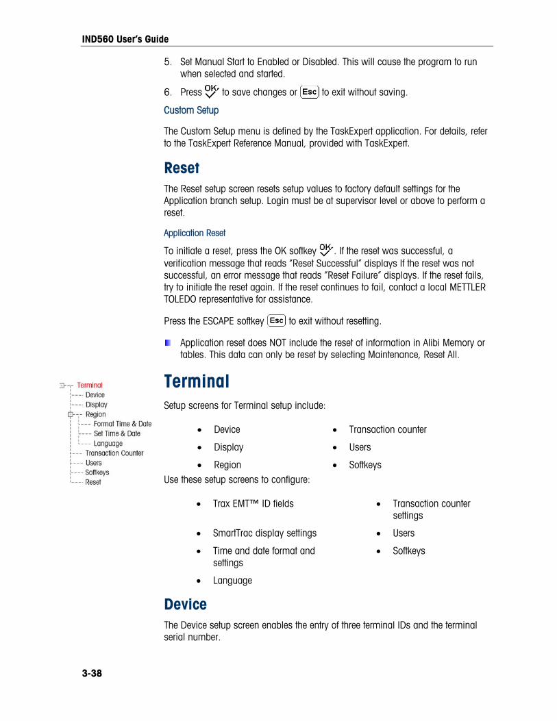
IND560 User’s Guide
5. Set Manual Start to Enabled or Disabled. This will cause the program to run when selected and started.
6. Press to save changes or to exit without saving.
Custom Setup
The Custom Setup menu is defined by the TaskExpert application. For details, refer to the TaskExpert Reference Manual, provided with TaskExpert.
Reset The Reset setup screen resets setup values to factory default settings for the Application branch setup. Login must be at supervisor level or above to perform a reset.
Application Reset
To initiate a reset, press the OK softkey . If the reset was successful, a verification message that reads “Reset Successful” displays If the reset was not successful, an error message that reads “Reset Failure” displays. If the reset fails, try to initiate the reset again. If the reset continues to fail, contact a local METTLER TOLEDO representative for assistance.
Press the ESCAPE softkey to exit without resetting.
Application reset does NOT include the reset of information in Alibi Memory or tables. This data can only be reset by selecting Maintenance, Reset All.
Terminal Setup screens for Terminal setup include:
• Device • Transaction counter
• Display • Users
• Region • Softkeys Use these setup screens to configure:
• Trax EMT™ ID fields • Transaction counter settings
• SmartTrac display settings • Users
• Time and date format and settings
• Softkeys
• Language
Device The Device setup screen enables the entry of three terminal IDs and the terminal serial number.
3-38

IND560 User’s Guide
Terminal ID
Up to three terminal IDs can be entered on the Device setup screen. When the Terminal ID text box is selected, the softkeys become alpha keys. Use the alpha keys to enter up to three terminal IDs. Press the ENTER key to accept the ID entered. These ID fields display in the information recall when the SYSTEM INFORMATION softkey is pressed after the RECALL softkey .
Serial Number
When the Serial Number text box is selected, the softkeys become alpha keys. Use the alpha keys to enter the terminal’s serial number. The serial number is located on the back of the terminal. Press the ENTER key to accept the serial number entered.
Display Use the Display setup screen to set the screensaver timeout and the SmartTrac™ size settings.
Screensaver
Enter the number of minutes (up to two digits) that must elapse with no scale motion and no keypad activity before the screensaver is shown (replaces the view on the display screen). If motion is detected or any key is pressed, the screen saver automatically exits and its time is reset. A keystroke used to exit the screen saver mode is ignored for all other purposes.
A setting of 0 in the Screensaver field will disable the screensaver.
Rate Display
This field determines whether the rate displays on the home screen. The option is not available when SmartTrac is enabled.
SmartTrac Size
SmartTrac refers to a graphical display visualization used to represent measured values. The display is either a bar graph (if material transfer is selected as the target mode) or an over/under display (if over/under is selected as the target mode).
The graphical display varies in terms of the amount of data displayed. While the SmartTrac graphic remains constant in size, the “small” setting includes minimal information, while the “large” setting displays the description as well as the target and limit values.
Examples of different sizes of SmartTrac displays are as follows:
3-39

IND560 User’s Guide
Material Transfer Mode Over/Under Mode
Small
Medium
Large
Figure 3-12: SmartTrac Display Sizes, Material Transfer and Over/Under Modes
Use the SmartTrac Size selection box to select a setting for the SmartTrac graphical display. Selections include None, Large, Medium, and Small.
If this parameter is set to None, SmartTrac will not display when the SmartTrac softkey is pressed at the home screen. Instead, a message will display: “This Function is disabled.”
Rate Display
If a Rate is configured at Scale > Rate, it may be displayed on the home screen or not, depending on whether this value is set to Enabled or Disabled. The option to display Rate does not appear when SmartTrac is set to any value other than None.
Region The region setup screens enable configuration of:
Time and date format
Time and date settings
Language
Format Time & Date
Selection boxes on this setup screen enable formatting of:
Time Format
12:MM (12-hour clock with hour and minutes displayed)
12:MM:SS (12-hour clock with hour, minutes, and seconds displayed)
24:MM (24-hour clock with hour and minutes displayed) 3-40

IND560 User’s Guide
3-41
s displayed)
Two-digit day, month, year)
acter month, four-digit year)
o-digit day, four-digit year)
cter month, two-digit day)
e & Date
inutes, day, month, and year on this setup screen’s text fields and
24:MM:SS (24-hour clock with hour, minutes, and second
Date Format
DD MM YY (
DD MMM YYYY (Two-digit day, three-char
MM DD YY (Two-digit month, day, year)
MMM DD YYYY (Three-character month, tw
YY MM DD (Two-digit year, month, day)
YYYY MMM DD (Four-digit year, three-chara
Date Field Separator
/ (slash)
- (dash)
. (period)
(space)
None
Set Tim
Enter the hour, mselection boxes. The terminal automatically adjusts the date for a leap year, and a battery backup maintains the time and date settings in the event of a power outage.
Manual setting of the time is necessary for daylight savings time
e numeric keypad to enter the hour in the Hour field text box. Use the AM/PM
ric keypad to enter the minutes in the Minutes field text box.
he numeric keypad to enter the day in the Day field text box.
Month selection box to select the month.
e numeric keypad to enter the year in the Year field text box.
adjustments.
Hour
Use thselection box to select AM or PM. The AM/PM selection box only displays if the time format is set to 12:MM or 12:MM:SS on the Format Time & Date setup.
Minutes
Use the nume
Day
Use t
Month
Use the
Year
Use th

IND560 User’s Guide
Language
Use the Language setup screen to specify the language for terminal operations.
Display Messages
Use the Display Messages selection box to select the language for messages that display on the terminal. Choices are:
• English
• French
• German
• Italian
• Spanish
Keypad Selection
Use the Keypad Selection selection box to select the language for the keypad characters that display on the terminal. This selection determines which international characters are available in the alphabetic data entry softkeys. Choices are:
• Dutch
• English
• French/German
• Nordic/German
• Spanish/Italian/Portuguese
External Keyboard
Use this parameter to select the language for the external USB keyboard. The optional Ethernet/USB/COM3 board must be installed to use an external keyboard. The language choices are:
• English
• French
• German
• Italian
• Spanish
Transaction Counter The transaction counter is a seven-digit register that tracks the total transactions that are completed on the terminal. When the value reaches 1,500,000, the next transaction causes a roll-over to 0000001. Use the Transaction Counter setup screen to configure transaction counter operations.
Transaction Counter
Use the Transaction Counter selection box to enable or disable the transaction counter.
3-42
IND560 User’s Guide
Counter Reset
Use the Counter Reset selection box to enable or disable manual resetting of the counter.
Next Transaction
The value for the counter for the next transaction displays in the Next Transaction field. The RESET COUNTER softkey can be assigned to the home screen (refer to Appendix E, Softkey Mapping), giving direct access to the Transaction Counter screen. If Counter Reset is enabled, the counter can be set to 0000000001 by pressing the RESET softkey. A value greater than one can also be entered manually in the Next Transaction field.
Users The IND560 terminal is pre-configured with two usernames: “admin” and “anonymous”. Neither of these usernames has a password. Without passwords, there will be no security challenge for entering setup and making changes. If a password is entered for “admin”, a login will be required before changes can be made in setup. These two default usernames cannot be deleted but passwords may be entered for them. All functions of the terminal will be available to all users until a password is entered for the default admin user.
To modify and/or enter a password for a username:
1. Move focus to the username to be edited.
2. Press the EDIT softkey to access the User Edit screen.
3. Press the DOWN navigation key to view the second screen, which displays the Password and Confirm Password fields.
4. Enter the desired password in the Password and Confirm Password fields.
5. Press the OK softkey to accept the password as entered.
6. Press the ESCAPE softkey to exit without saving the password.
Passwords are case-sensitive.
All numbers and all characters available in the alpha keys are valid for use in passwords.
Be sure to store a record of the password in a safe place. Without the correct password access to the setup menu will not be possible.
To enter a new username and password:
1. Press the INSERT softkey to access the User Edit screen.
2. Enter the desired username in the Username field.
3. Use the Access selection box to assign the appropriate access level to the user. The following access levels are available:
• Administrator – An administrator has unlimited access to all set-up parameters in the terminal. There can be multiple administrator users.
3-43

IND560 User’s Guide
• Maintenance – Next lower level of access.
• Supervisor – Next lower level of access.
• Operator – Lowest level of access. 4. Press the DOWN navigation key to view the second screen, which displays the
Password and Confirm Password fields.
5. Enter the desired password in the Password and Confirm Password fields.
6. Press the OK softkey to accept the username and password as entered.
7. Press the ESCAPE softkey to exit without saving the username and password.
8. Press the DELETE softkey to delete a username from the table on the Users screen. Usernames "admin" and "anonymous" cannot be deleted.
9. To restore the factory default setting (by deleting all users except the “Admin” and “Anonymous” users and restoring the passwords to null), press the CLEAR
softkey and then OK to confirm the action.
Softkeys Add or rearrange the softkeys on the terminal's main menu on the softkeys setup screen. Appendix E, Softkey Mapping, provides a more detailed explanation of the softkeys.
When the softkeys setup screen opens, focus is on the softkey position numbers located above the icons.
Two softkeys, INFORMATION RECALL and SETUP , are automatically placed in the softkey setup. The default setting for the placement of these softkeys is in positions 9 and 10.
The INFORMATION RECALL and SETUP softkeys must always be assigned a position. They can be moved or multiple copies of them can exist but there must always be at least one appearance of them. They cannot be deleted. All other softkeys may be added or deleted as desired.
Adding a softkey to the home pages of the terminal does not automatically enable the softkey’s function. Most softkeys must also be enabled in setup too. For instance, adding the UNITS SWITCHING softkey does not automatically enable units switching – the units must also be enabled in the Scale branch of setup. If a softkey has been added in setup but does not appear on the home page, check that the setup parameters for that function have been enabled.
The following softkeys are available for assignment to the home page:
• None • Recall Info* • Target Start
• Alibi Memory • Repeat Print • Target Table
• Calibration Test • Reports • Task 1**
• Comparators • Reset Transaction Counter • Task 2**
• Custom Trigger 1 • Setup* • Task 3**
3-44

IND560 User’s Guide
• Custom Trigger 2 • SmartTrac • Task List**
• Custom Trigger 3 • Tare Table • Time & Date
• ID • Target • Unit Switching
• MinWeigh • Target Control • x10 Display
* Cannot be removed from home screen or edited.
** Only available when TaskExpert™ or an application is installed.
Press the UP, DOWN, LEFT and RIGHT navigation keys to navigate among the softkey position numbers. Softkeys can be added, removed, and positioned using the softkeys:
Edit
Changes the softkey in the selected position to another softkey or to none, which leaves the softkey position blank. Editing a blank position does not move the position of following softkeys.
Insert Inserts a softkey into a selected position. All other softkeys located at
or after that position increase position number by one.
Delete Deletes a softkey in a selected position. All other softkeys located at or after that position decrease position number by one.
Clear Clears all softkey assignments except INFORMATION RECALL and SETUP softkeys. These will be shown in positions 1 and 2 respectively.
Reset The Reset setup screen resets setup values to factory default settings for the Terminal branch of setup.
Terminal Reset
To initiate a reset, press the OK softkey . If the reset was successful, a verification message that reads “Reset Successful” displays If the reset was not successful, an error message that reads “Reset Failure” displays. If the reset fails, try to initiate the reset again. If the reset continues to fail, contact a local METTLER TOLEDO representative for assistance.
Press the ESCAPE softkey to exit without resetting.
3-45
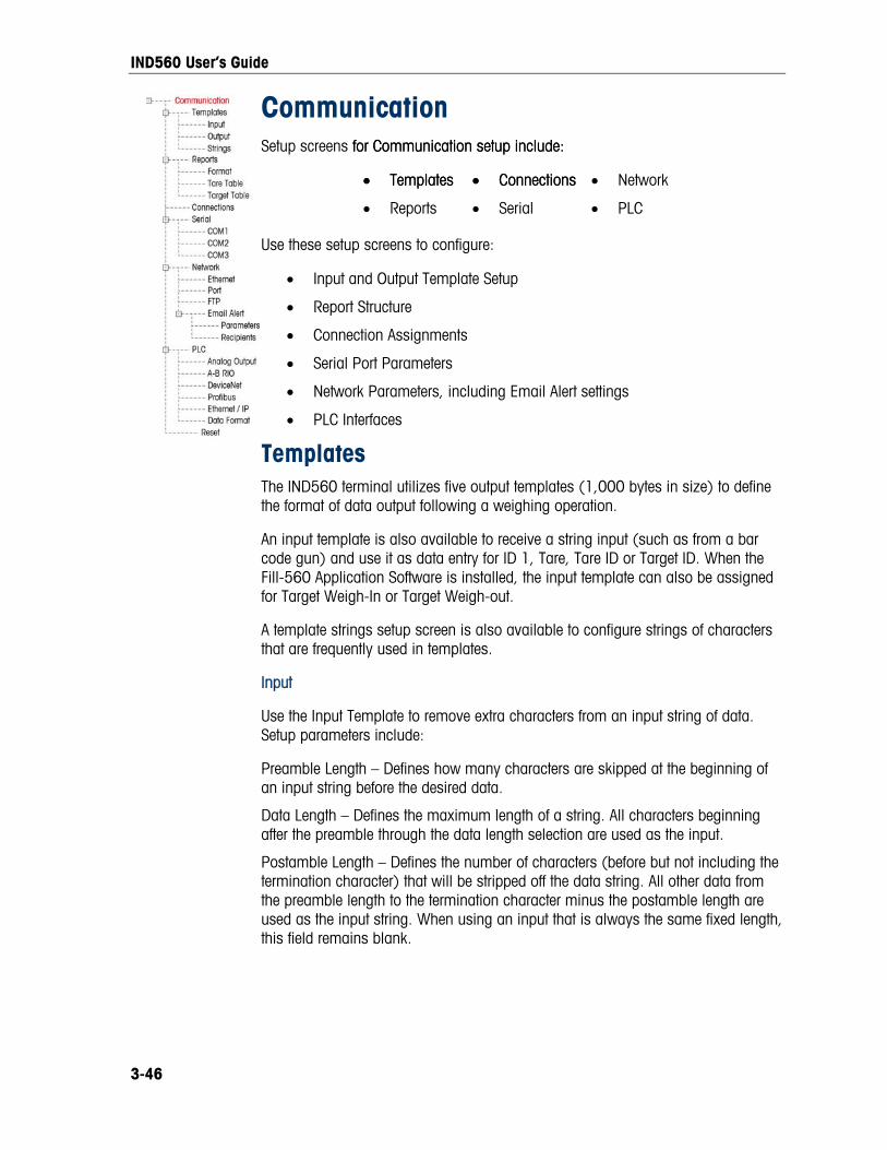
IND560 User’s Guide
Communication Setup screens for Communication setup include: for Communication setup include:
• Templates • Templates • Connections• Connections • Network
• Reports • Serial • PLC
Use these setup screens to configure:
• Input and Output Template Setup
• Report Structure
• Connection Assignments
• Serial Port Parameters
• Network Parameters, including Email Alert settings
• PLC Interfaces
Templates The IND560 terminal utilizes five output templates (1,000 bytes in size) to define the format of data output following a weighing operation.
An input template is also available to receive a string input (such as from a bar code gun) and use it as data entry for ID 1, Tare, Tare ID or Target ID. When the Fill-560 Application Software is installed, the input template can also be assigned for Target Weigh-In or Target Weigh-out.
A template strings setup screen is also available to configure strings of characters that are frequently used in templates.
Input
Use the Input Template to remove extra characters from an input string of data. Setup parameters include:
Preamble Length – Defines how many characters are skipped at the beginning of an input string before the desired data.
Data Length – Defines the maximum length of a string. All characters beginning after the preamble through the data length selection are used as the input.
Postamble Length – Defines the number of characters (before but not including the termination character) that will be stripped off the data string. All other data from the preamble length to the termination character minus the postamble length are used as the input string. When using an input that is always the same fixed length, this field remains blank.
3-46

IND560 User’s Guide
Termination Character –+ Used to signal the end of the string input. The termination character can be any ASCII control character. If None is selected, the three-second timeout feature terminates the entry. In addition to None, selections available from the selection box include:
SOH STX ETX EOT ENQ ACK BEL BS
HT LF VT FF CR SO SI DLE
DC1 DC2 DC3 DC4 NAK SYN ETB CAN
EM SUB ESC FS GS RS US
Refer to Appendix G for ASCII control character definitions and functions.
Assignment – Determines how the input data should be used. Choices are:
ID1 Input populates the ID1 Shared Data variable.
Keypad Used in conjunction with ID Mode – data that would normally be entered using the numeric keypad or on-screen alpha keys may be scanned in during an ID Mode sequence.
Tare Enters data as a preset tare value
Tare ID Uses value as an ID lookup in the tare table
Target ID Uses value as an ID lookup in the target table
Target Weigh-in
Uses value as an ID lookup in the target table and assigns it as the Active Weigh-in target (Fill-560 feature only)
Target Weigh-out
Uses value as an ID lookup in the target table and assigns it as the Active Weigh-out target (Fill-560 feature only)
There is also a three-second timeout feature that tracks the amount of time between characters. If this three-second time is exceeded, the string is considered terminated.
Output
The Output Template setup screen enables configuration of the output data formats and a header or footer for the Repeat Print function.
To add the “DUPLICATE” designation to a repeat print of an output template, select either Header or Footer from the Repeat Print Field dropdown menu highlighted in Figure 3-13.
Figure 3-13: Repeat Print Field Setup
3-47

IND560 User’s Guide
To view elements in a template or create a new template, select the desired template from the Template selection box. Five templates are available (Template 1–Template 5).
Press the VIEW TABLE softkey to access the selected template’s view screen, which lists each element configured for the template.
Press the COPY softkey to open the copy screen, which enables the elements from one template to be copied to another template.
Press the CLEAR softkey to clear all elements from the selected template. A warning screen displays as a precaution.
Press the EXIT softkey to return to the menu tree.
Each element is defined by the data type, actual data, justification and length. Elements may be edited, added (inserted), or deleted individually. A leading zero fill function is available for certain fields.
Editing
1. Press the UP and DOWN navigation keys to select a record to edit.
2. Press the EDIT softkey to open the setup screen for the record where edits can be made. The element number cannot be edited.
3. Select the element type from the Type selection box. Four element types are available:
CR/LF – A combination carriage return and line feed.
SDName – The name of a Shared Data variable from the terminal.
Special Character – Control characters from a standard ASCII chart. Refer to Appendix G, ASCII Standard and Control Characters.
String – A string of characters to print.
Press ENTER to confirm the element type selection. Depending on which type is selected, additional configuration options will appear.
4. Press the OK softkey to return to the template setup screen when editing of the element is complete.
5. Press the ESCAPE softkey to return to the template setup screen without saving the element edits.
3-48

IND560 User’s Guide
Template Editing Options
Table 3-3 lists the editable fields that appear for each Element Type and Format selection. Fields that are not available are indicated with a dash (–).
Table 3-3: Template Element Editing Options
Element Type
Data Repeat Count
Format Length Leading Zero
Fill
CR/LF − Blank** − − −
Default − −
Centered, Left Blank** − SDNAME Blank* (Refer to Table 3-4) −
Right Blank** Enabled/Disabled
Special Character ASCII character list − − − −
Default − − String Blank* Blank**
Center, Left, Right Blank** −
* Alphanumeric entry field ** Numeric entry field
Repeat Count
A numeric value that sets the number of times the Data will repeat. For example, if the string data entered is an asterisk (*), a repeat count value of 20 would produce a row of 20 asterisks: ********************.
Format & Length
The Format & Length options are Default, Centered, Left, and Right. These describe the justification of the data within the length of the field.
The Default value is fixed, and Length cannot be defined here.
For SD name and String data, the Centered, Left and Right formats are accompanied by a Length field. After choosing the format, focus moves to the Length entry box. This value determines how long the element will be – the data will be positioned within a string of the length entered. Refer to the Notes on Format & Length, below.
Leading Zero Fill
In the case of Right-formatted SDName data, Leading Zero fill may be enabled or disabled. Normally, Leading Zero Fill will be disabled, which means spaces will be used to fill in leading non-significant data. If enabled, Leading Zero Fill will fill in any leading spaces of the data with zeroes. The following examples of 4 characters in output data defined as 8 characters long show the use of Leading Zero Fill:
Leading Zero Fill disabled:
Leading Zero Fill enabled:
3-49

IND560 User’s Guide
3-50
Notes on Format & Length
If data for an element includes more characters than the value entered for Length, the output data will be cut off. For example, if the number of characters entered under format on the Output Template Edit Screen is six, and data for a string that contains eight characters is entered, only six of the characters from the data string will print. If data for a string that contains four characters is entered, all of the characters from the data string will print.
The characters and alignment of the printed data are defined by the selected format:
Example 8-character string of ABCDEFGH in a 6-character element: Center: Left: Right:
B C D E F G A B C D E F C D E F G H Prints the middle six characters from an eight-character string – drops first and last characters.
Prints the first six characters from an eight-character string – drops the last two characters.
Prints the last six characters from an eight-character string – drops the first two characters.
Example 4-character string of ABCD in a 6-character element:
A B C D A B C D A B C D Space Space Spaces Spaces
Prints all four characters from a four-character string in a centered position, leaving a space at the beginning and a space at the end.
Prints all four characters from a four-character string in a left-justified position, leaving two spaces at the end.
Prints all four characters from a four-character string in a right-justified position, leaving two spaces at the beginning.
In Table 3-4, where dashes appear in the SDName (e.g. sd--08), this means that there are more than one instance of the share data variable. The instance number appears in place of the dashes (e.g. sd0308, for the third comparator’s target comparison operator). For a full list of Shared Data fields, please refer to the IND560 Terminal Shared Data Reference (document # 64058660) found on the documentation CD.
Table 3-4: Example Shared Data Names for Use in Templates
IND560 Data Field SDName Length (A/N = alphanumeric)
Terminal
Scale ID cs0103 20 A/N
Base Serial Number ce0138 13 A/N
Terminal Serial Number xs0105 13 A/N
Terminal ID#1 xs0106 20 A/N
Terminal ID#2 xs0107 20 A/N
Terminal ID#3 xs0108 160 A/N
Current Date xd0103 11 A/N
Current Time xd0104 11 A/N
Transaction Counter Value xp0101 9 A/N
Grand Total Value tz0101 12 A/N
Grand Total Count tz0102 9 A/N

IND560 User’s Guide
3-51
IND560 Data Field SDName Length (A/N = alphanumeric)
Subtotal Value tz0103 12 A/N
Subtotal Count tz0104 9 A/N
ID Mode Prompts 1-20 pr0131-pr0150 20 A/N
ID Mode Prompt Responses 1-20 pa0101-pa0120 51 A/N
Message 01, 02, etc. aw0101, 0102,… 100 A/N
Templates 1 - 5* pt0101− pt0105 As programmed
Template Strings 1–20 pt0111 − pt0130 51 A/N
Targets
Target Description sp0101 20 A/N
Target Value sp0105 12 A/N
Target Units sp0120 3 A/N
Fine Feed sp0110 12 A/N
Spill Value sp0109 12 A/N
+ Tolerance Value (weight) sp0111 12 A/N
− Tolerance Value (weight) sp0112 12 A/N
+ Tolerance Value (%) sp0114 12 A/N
− Tolerance Value (%) sp0115 12 A/N
Comparator names 1-5 sd--01 21 A/N
Comparator target coincidence values 1 - 5 sd--05 12 A/N
Comparator target comparison operators 1-5 sd--08 5 A/N
Comparator second weight range values 1-5 sd--09 12 A/N
Comparator second weight range comparison operators 1-5 sd--10 5 A/N
Weights
Scale Mode (Gross/Net) ws0101 1 A/N (G or N)
Tare Source Description ws0109 2 A/N “T<space>”, or “PT”
Displayed Tare Wt. ws0110 12 A/N
Displayed Gross Wt. wt0101 12 A/N
Displayed Net Wt. wt0102 12 A/N
Displayed Wt. Units wt0103 3 A/N
3rd Weight Unit Gross Weight wt0104 13 A/N
3rd Weight Unit Net Weight wt0105 13 A/N
3rd Units wt0106 3 A/N
Displayed Rate wt0108 13 A/N
Rate Time Units cs0107 1 A/N
Rate Weight Units cs0108 1 A/N

IND560 User’s Guide
Length IND560 Data Field SDName (A/N = alphanumeric)
Custom Unit Name cs0112 12 A/N
Custom Unit Conversion Factor cs0113 12 A/N
* Using a template field code within another template will insert the entire template into the new template.
Printing Multiple Weight Units
Note that if a third weight unit is defined, it can be named in a template so that it appears in the output data together with the displayed unit. However, if the third unit is currently displayed on the terminal, it will appear twice in the data output. Therefore, if the output is to include both primary and 3rd weight units, ensure that the primary unit data is displayed when the data output is initiated.
Secondary Units are not available for multiple unit printing.
Inserting
Press the UP and DOWN navigation keys to select a location in the list of elements to insert a new element. Press the INSERT softkey to open the setup screen to create a new record. Configure the parameters as described under Editing. All following elements are moved down one position.
Deleting
Press the UP and DOWN navigation keys to select an element to delete. Press the DELETE softkey to delete the element.
Test Printing
Press the TEST PRINT softkey to perform a test print of the template being configured.
Strings
The Template Strings setup screen defines strings of characters that are frequently used in template messages. Template strings can be viewed, edited, inserted, deleted, or printed.
To view template strings:
1. Use the Search Field selection box to select ID or String and enter information in the Data field to limit the search, or do not enter any search limits to view all template strings.
2. Press the START SEARCH softkey . The String Search View screen displays the search results. Only records with non-null values display. Records are ordered by ID, with the lowest ID number shown first.
3. Press the UP and DOWN navigation keys to scroll up and down the screen in order to view all strings listed.
3-52

IND560 User’s Guide
Editing
Note that not all keyboard characters are available when entering informatiousing the IND560 keypad. However, characters such as ~ and | c
n an be
included in a template created using the InSite software. They will be recognized by the IND560 when the template is downloaded, will display correctly, and will be included in the template when it is printed.
The [, ] and {, } characters have been added to the list of characters available from the terminal softkeys. These characters can be found in firmware versions 3.02 and higher.
1. Press the UP and DOWN navigation keys to select (highlight) the string recordto be edited.
2. Press the EDIT softkey to open the record for editing. The edit screen will be
he alpha keys will display.
e a
Press ENTER when complete.
shown with focus on the “Text” label. This is the only editable field on the screen. The ID number cannot be changed.
3. Press ENTER to access the text field. T
4. Use the alpha keys and the numeric keypad to edit the string. A string can bmaximum of 50 characters.
5.
6. Press the OK softkey to accept the edited record and return to the String Search View screen.
softkey to return to the String Search View screen without 7. Press the ESCaccepting the changes to the string.
Inserting
1. Press the INSERT softkey to create a new record. An edit screen will be shown with “ID” and “Text” labels.
2. Press the UP and DOWN navigation keys to select the field to enter.
red already exists, an error display e acknowledged and a new ID entered.
and
3. Press ENTER to access the field. When entering the ID field, the value shown is the first unused ID.
4. Use the numeric keypad to enter an ID number from 1 to 20.
5. Press ENTER when complete. If the ID entewill be shown. The error must b
6. If the TEXT field is entered, the alpha keys will display. Use the alpha keys the numeric keypad to edit the text string.
7. Press ENTER when complete.
8. Press the OK softkey to accept the new record and return to the String Search View screen.
softkey 9. Press the ESC to return to the String Search View screen without rdaccepting the new reco .
Deleting
Press the DELETE softkey to delete a template string from the list. 3-53

IND560 User’s Guide
Printing
1. Press the PRINT softkey to print the list.
3-54
2. Press the EXIT softkey to return to the String Search Screen.
3. Press the EXIT softkey again to return to the menu tree.
Reports The reports setup screens enable configuration of the structure of tare and target
generated by the IND560 terminal. The reports setup screens
• Tare Table
width of the reports
• Narrow (40) – 40 character-wide reports
eader field specifies the number of blank lines (CR/LF) to be placed at the
The Title selection box enables a default title line to be printed at the top of the date will print in the format selected at Terminal > Region >
A repeated character may be selected as a separator between printed records in the be u ces in the
re:
parator between records) (equal symbols)
s)
ield specifies the number of blank lines (CR/LF) to be placed at the end
table reports that areinclude:
• Format
• Target Table
Format
Use the selection box for the Format field to select the
• Wide (80) – 80 character-wide reports
Header
The Hstart of each report.
Title
report. Time and Format Time & Date.
Record Separator
report. This step selects the character to sed. The character choiselection box a
None (no se =
* (asterisks) CR/LF (blank line)
- (dashe
For example, if * (asterisks) is selected, the resulting line separator will appear as follows:
*************************************************************************
Footer
The Footer fof each report.

IND560 User’s Guide
Tare Table
3-55
Use this setup screen to select which fields in the Tare Table will print when a Tare Ta ction of Ap disabled. Fields t
Tare • n (number of transactions)
ble Report is printed. More details are provided in the Reports sependix D, Communication
hat can be enabled os. The ID field is always printed; it cannot be r disabled include:
•
• Description • Total (accumulated total tare weights)
Target Table
Use this setup screen to select which fields in the Target Table will print when a Target Table Report is printed. More details are provided in the Reports section of Appendix D, Communications. The ID field is always printed; it cannot be disabled.
t can be enabled or disabled vary depending on how the Target Table is configured (as described in the Application branch under Memory
ud
• Description • +/- Tolerances • Fine Feed
• Spill • +/- Limits
Fields that display and tha
setup).
Fields available incl e:
• Target
If the Target mode is disabled, this branch cannot be expanded.
Connections The connections setup screen shows the physical port connections that have been programmed for the terminal. This includes the standard serial port COM1, optional COM2 and COM3 serial ports, and the optional Ethernet port. The optional ports are
and available in the selection of ports.
connections are programmed, nothing will be available on the COM ports or Ethernet.
The following fu connections screen:
Deleting • Clearing
ion
2.
only available if the option board has been installed. When the optional Ethernet/USB/COM3 board is installed, the COM2 serial port is not supported, will not be
This screen defines what type of communication will occur over each port. If no
nctions are available via softkeys on the
• Editing • Inserting
•
To edit or insert connection assignments:
1. Press the UP and DOWN navigation keys to select (highlight) a connectassignment in the list.
Press the EDIT softkey to open the setup screen for editing a specific connection assignment or press the INSERT softkey to create a new connection assignment.
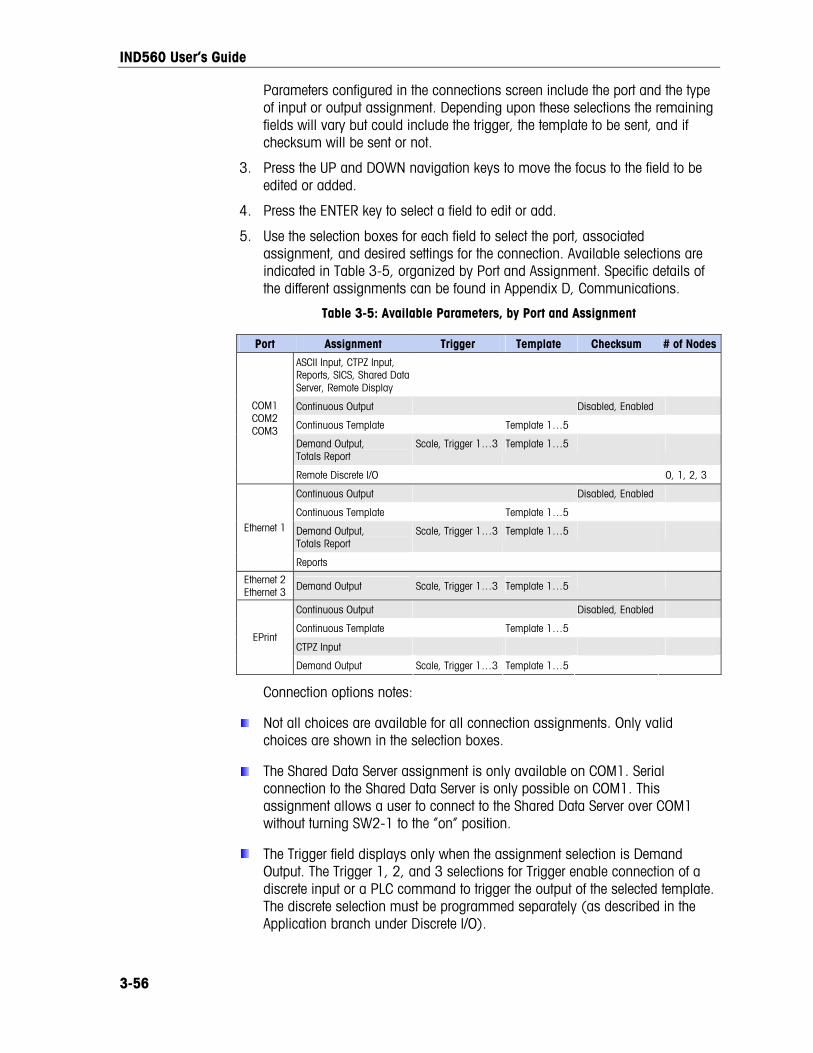
IND560 User’s Guide
3-56
assignment. Depending upon these selections the remaining
late to be sent, and if
5. Use the se assignment, and desired settings for the connection. Available selections are
icated , organiz ort a men dthe d be found in Appendix D,
ilable Parameters, by Port and Assignment
Parameters configured in the connections screen include the port and the typeof input or output fields will vary but could include the trigger, the tempchecksum will be sent or not.
3. Press the UP and DOWN navigation keys to move the focus to the field to be edited or added.
4. Press the ENTER key to select a field to edit or add.
lection boxes for each field to select the port, associated
ind in Table 3-5 ed by P nd Assign t. Specific etails of ifferent assignments can
Table 3-5: Ava
Communications.
Port Assignment Trigger Template Checksum # of Nodes ASCII Input, CTPZ Reports, SICS, SharServer, Remote Display
Input, ed Data
Continuous Output Disabled, Enabled
Continuous Template Template 1…5
Demand Output, Totals Report
Scale, Trigger 1…3 Template 1…5
COM1 COM2 COM3
O Remote Discrete I/ 0, 1, 2, 3
Continuous Output Disabled, Enabled
Continuous Template Template 1…5
Demand Output, Totals Report
Scale, Trigger 1…3 Template 1…5 Ethernet 1
Reports
Ethernet 2 Ethernet 3 Demand Output Scale, Trigger 1…3 Template 1…5
Continuous Output Disabled, Enabled
Continuous Template Template 1…5
CTPZ Input EPrint
Demand Output Scale, Trigger 1…3 Template 1…5
Connection options notes:
Not all choices are available for all connection assignments. Only valid choices are shown in the selection boxes.
The Shared Data Server assignment is only available on COM1. Serial connection to the Shared Data Server is only possible on COM1. This assignment allows a user to connect to the Shared Data Server over COM1 without turning SW2-1 to the “on” position.
The Trigger field displays only when the assignment selection is Demand
late. be programmed separately (as described in the
Application branch under Discrete I/O).
Output. The Trigger 1, 2, and 3 selections for Trigger enable connection of a discrete input or a PLC command to trigger the output of the selected tempThe discrete selection must

IND560 User’s Guide
The Template field displays only when the assignment selection is Demand Output, Continuous Template, or Totals Report. Only one template can be assigned to a connection.
The default template for the Totals Report is Template 5.
The Checksum field is available for continuous outputs only.
The SICS selection provides some Level 0 and Level 1 interface commands. Refer to Appendix D, Communications for details on the SICS protocol.
If usage conflicts occur, an alarm message displays.
EPrint offers a method to access the demand or continuous output data directlythrough the Ethernet port. Shared Data Server lo
gin and commands are not
, and reflects only the configured template data or the continuous output string. The EPrint port is accessible
ed ication > Network > Port.
required to register for the data. The data output string does not include any Shared Data Server response messages
only through the Ethernet interface’s secondary port, which can be configurin setup at Commun
The # of Nodes refers to the number of ARM100 Remote I/O modules that will be connected in series to the IND560.
Note that CTPZ over Ethernet is now available. This feature requires v4.xx firmware or higher.
6. Press the OK softkey to accept the connection parameters and return to the wh nt
7. Press the ESCAPE softkey
Connections setup screen en editing or adding the connection assignmeis complete.
to discard the connection parameters and
y
return to the Connections setup screen without saving the connection assignment edits or additions.
Press the DELETE softke to delete a connection assignment from the Connections list.
r all connection assignments in the Connections list, press the CLEAR To clea
3-57
softkey then press OK to confirm the action.
Press the EXIT softkey to return to the menu tree.
Serial Serial communication setup screens provide access to the communication parameters for the serial ports COM1, COM2, and COM3.
The COM2 and COM3 ports are only shown if the Ethernet/COM2/COM3 option
on the new Ethernet/USB/COM3 option board. RS-422 is not available on COM3 of this option board, so that selection is not listed if this option board is installed.
board has been installed.
Only COM3 is available

IND560 User’s Guide
3-58
If “Remote Discrete I/O” is selected as the port assignment at Communication > Connections, the port parameters are automatically preset and cannot be
COM1, COM2, and COM3
Baud
Use the Baud selection box to set the baud rate for the serial port. Options are:
600 2400 9600 38400 115200
ts
changed.
Use the COM1, COM2, and COM3 setup screens to configure the parameters forserial ports.
300 1200 4800 19200 57600
Data Bi
Use the Data Bits selection box to set the data bits to either 7 or 8 for the serial port.
Parity
Use the Parity selection box to set the parity to None, Odd, or Even for the serial port.
Flow Control
Use the Flow Control selection box to set the flow control to either None or XON-XOFF (software handshaking).
mand is received on a serial port configured for XON/XOFF a remaining in the port’s buffer will still be sent. Port buffers ing amounts of data:
es
COM2: 64 bytes
election box to select the serial port interface. Selections for
• RS-485
3 on the Ethernet/COM2/COM3 board include:
• RS-485
After an XOFF comhandshaking, datcontain the follow
COM1: 16 byt
COM3: 64 bytes
Interface
Use the Interface sCOM1 include:
• RS-232 • RS-422
Selections for COM2 include:
• RS-232
Selections for COM
• RS-232 • RS-422

IND560 User’s Guide
3-59
3 on the Ethernet/USB/COM3 board include:
2
data m
essing only. If the (Dynamic Host Configuration Protocol) DHCP Client setting is enabled, the IP
y
Use the UP and DOWN navigation keys to select the field to be edited. Press the edit the field or selection choice. The Ethernet branch includes the
enabled or disabled. If disabled, the IP address must manually be assigned in the following fields. If enabled, the terminal will be
n IP address by the network server. The IP address can then be viewed
Enter the IP address (or view if DHCP Client is enabled) for the IND560 terminal. up of digits has been entered, press ENTER to proceed to the next
Enter the subnet mask (or view if DHCP Client is enabled) for the IND560 terminal. of digits has been entered, press ENTER to proceed to the next
Enter the gateway address (or view if DHCP Client is enabled) for the IND560 nte d to
oup. The default value for the gateway is blank.
Selections for COM
• RS-23• RS-485
Network Network setup screens include Ethernet, Port, FTP and Email Alert.
Ethernet
Ethernet is available for TCP/IP transfer of data, connecting to InSite™, sharedserver access, connection via the EPrint port, email alerts, and FTP. The MediuAccess Control (MAC) Address cannot be edited; it is shown for information only. Setup for Ethernet allows static Internet Protocol (IP) addr
Address, Subnet Mask, and Gateway Address fields are assigned automatically bthe network and become read-only in the setup screens.
ENTER key tofollowing fields:
DHCP Client
The DHCP client can be
assigned ain the following fields.
IP Address
After each grogroup. The default value for the IP is 192.68.0.1.
Subnet Mask
After each group group. The default value for the subnet mask is 255.255.255.0.
Gateway Address
terminal. After each group of digits has been e red, press ENTER to proceethe next gr
After entry is complete, press the EXIT softkey to return to the menu tree
Port
The Port setup screen displays the primary Ethernet port number and also allowsecondary port number to be configured for the same Ethernet interface. The primary port is
s a
reserved for the Shared Data Server access, which is described in Appendix D. The secondary port allows for either Shared Data Server access or
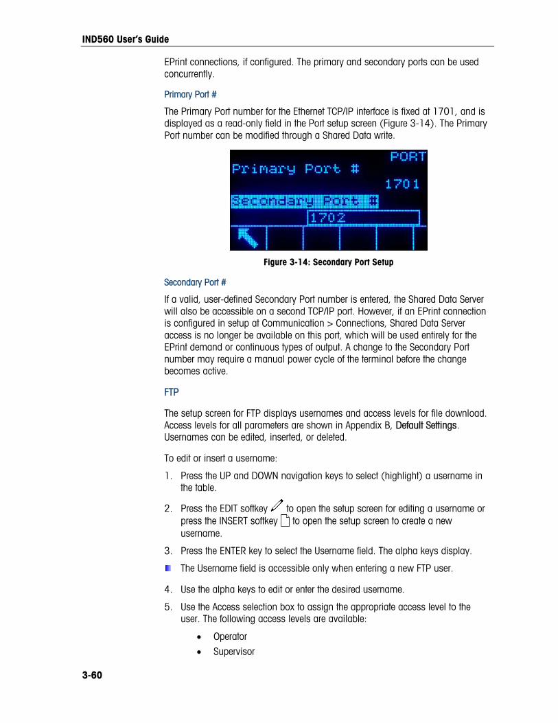
IND560 User’s Guide
3-60
nfigured. The primary and secondary ports can be used
The Primary Port number for the Ethernet TCP/IP interface is fixed at 1701, and is displayed as a read-only field in the Port setup screen (Figure 3-14). The Primary Port number can be modified through a Shared Data write.
EPrint connections, if coconcurrently.
Primary Port #
Figure 3-14: Secondary Port Setup
Secondary Port #
If a valid, user-defined Secondary Port number is entered, the Shared Data Serverwill also be accessible on a second TCP/IP port. However, if an EPrint connectis configured in setup at Communication > Connections, Shared Data Server access is no long
ion
er be available on this port, which will be used entirely for the EPrint demand or continuous types of output. A change to the Secondary Port
er may require a manual power cycle of the terminal before the change becomes active.
The setup screen for FTP displays usernames and access levels for file download. s are shown in Appendix B, Default Settings.
ername:
T softkey
numb
FTP
Access levels for all parameterUsernames can be edited, inserted, or deleted.
To edit or insert a us
1. Press the UP and DOWN navigation keys to select (highlight) a username in the table.
2. Press the EDI to open the setup screen for editing a username or press the INSERT softkey to open the setup screen to create a new username.
3. Press the ENTER key to select the Username field. The alpha keys display.
The Username field is accessible only when entering a new FTP user.
4. Use the alpha keys to edit or enter the desired username.
lection box to assign the appropriate access level to the ccess levels are available:
5. Use the Access seuser. The following a
• Operator
• Supervisor
IND560 User’s Guide
• Maintenance
• Administrator
3-61
the
softkey
6. Press the DOWN navigation key to view the second screen, which displays Password and Confirm Password fields.
7. Enter the desired password in the Password and Confirm Password fields.
8. Press the OK to accept the username and password as entered.
key9. Press the ESCAPE soft to exit without saving the username and password.
Press the DELETE softkey to delete a username from the table on the Users screen.
To clear all usernames from the list and leave only the default username “admin”, press the CLEAR softkey then OK to confirm the action.
lem, or ation expires. Note that the Ethernet connection used to send email
unication > Connections.
g four groups of numbers, representing the IP address of the
hanumeric entry field permitting the IND560’s email address to be
phanumeric entry field, used to give the IND560 a unique name that
numeric entry field defines the Subject field of the email to be set. Default
ents of email alerts, together with the condition un h they will receive an email. The following actions are available on the Em ipients screen:
Email Alert
The IND560 can be configured to send email alerts when it encounters a calibration change or calibration failure that might indicate a hardware probwhen calibralerts is separate from those configured at Comm
Parameters
This screen permits four parameters to be set:
SMTP Server IP
This value is set usinmail server the IND560 will use to send alerts. Default is 0.0.0.0.
Sender Email Address
This is an alpset. Default is blank.
Sender Name
This is an alwill appear in the “From” field of alert emails. Default is “IND560.”
Subject Line
This alphais “Scale Cal Alert.”
Recipients
This screen is used to define recipider whicail Rec
Softkey Function
EXIT Returns to the setup menu tree.

IND560 User’s Guide
Softkey Function
EDIT Opens the Email Recipients Edit screen, permitting param
for the selected recipienteters
to be edited.
NEW Opens the New Email Recipien
recipient to be defined. t screen, allowing a new
D ELETE Deletes the selected recipient.
TEST Sends an email alert messageMessage,” to the recipient currently selected.
, titled “Email Alert Test
The NEW and EDIT screens offer the same options:
Email Address
This alphanumeric entry field is used to enter the recipient’s email address. Default is blank. Up to 6 recipients can be configured.
3-62
Note: Use the decimal key on the IND560 front panel to enter the period email address.
Alert
s. The default is None. Table 3-6 lists all the events that trigge ent when Alert On is set to Failures are indicated by
6: Calibration Alerts
in each
On
Available options are None, All, Failurer an email alert. Messages san asterisk.
Table 3-
Event Emai l Message Subject
Completi bration on of CalFREE cali CalFREE complete
After each ste on Calibration complete p in step calibrati
Calibration expired C alibration expired*Failing a calibration test Cal. test failed *Passing a calibration test Cal. test passed
Completion of a zero capture from the Calibration page Zero captured
Completion of a span capture from the Calibration page Calibration completed
PLC The PLC parameters arescreens include:
only available when a PLC option is installed. PLC setup
ut
• Modbus TCP
• Analog Outp
• A-B RIO
• DeviceNet
• PROFIBUS
• EtherNet/IP

IND560 User’s Guide
3-63
rmat
10 volt
the displayed weight or the gross weight.
se the appropriate source from the Source field selection box. Selections
defined by a Task Expert application)
ed Wt.
ht
Weight
•
Scale from the Channel selection box. A selection of None
ter the value at
• Data Fo
Analog Output
The analog output of the IND560 terminal provides either 4 - 20 mA or 0 -DC outputs depending on how the connection is wired. The output can be configured to represent either
To configure analog output:
1. Chooare:
• None
• Application (Source as
• ABS – Display
• ABS – Rate*
• Displayed Weig
• Gross
Rate*
*Available only when Rate is enabled
2. Select either None or disables the output.
3. On the second screen of this setup branch, the zero and span values for theanalog output can be adjusted. These values can be for weight or rate, depending on the selected source. In the Zero Value field, enwhich the “zero” output of the analog signal should occur.
4. If these preprogrammed values do not provide the exact outputs required, theymay be trimmed by using the ZERO and SPAN softkeys located at the bottom of the screen as follows:
5. Press the ZERO softkey to initiate the zero fine-tuning process or the SPAN softkey to initiate the span fine-tuning process. In either case, a warning screen offers two options – OK to continue with the operation, or EXIT to return to the Analog Output screen without making any adjustment.
6. The analog output signal value will change during this procedure – ensurthe PLC or other control equipment is discon
e that nected. A warning message
displays asking for verification to continue.
7. Once the OK softkey has been pressed, the zero fine-tuning or span fine-tuning operation begins. A message screen appears, showing the current value of the analog output signal. Use the softkeys that display to adjust the signal if necessary as follows:
Bump Down (faster adjustm n)ent dow Nudge Down
(slower adjustme n)nt dow
Bump Up (faster adjustment up) Nudge Up
(slower adjustment up)
8. Press the EXIT softkey to return to the previous screen.

IND560 User’s Guide
A-B RIO
The Allen-Bradley Remote I/O (A-B RIO) network is an Allen-Bradley proprietary network protocol that permits certain PLCs to communicate to additional racks of input and output devices or to other peripheral devices that implement the RIO interface.
Additional interface information and programming examples can be found in the IND560 Terminal PLC Interface Manual, which is included on the documentation CD.
The A-B RIO setup screen is used to configure A-B RIO as a PLC interface option.
Node Address
Each IND560 Terminal connected to the network represents one physical node; however, the addressing of the node is defined as a logical rack address. This address is determined by the system designer, then configured in the IND560 Terminal by selecting the Node Address text box and using the numeric keypad to enter the appropriate node address (0–62).
Prior to the Node Address text box is a selection field allowing the user to enter the node address in either:
• Decimal
• Octal Figure 3-13 shows the new A-B RIO setup screen for Node Address.
Figure 3-15: A-B RIO Node Address Setup Screen
Start Quarter (Group)
Each scale occupies a quarter rack (single group) in the RIO address space and the quarter (group) may be defined as the first (0), second (2), third (4), or fourth (6) quarter (group) of a rack. Designate the location of the PLC that is the highest quarter used in a logical rack by using the selection box to select the appropriate start quarter address 1–4 (group 0–6).
Last Rack
The IND560 configuration selections enable designation of the last rack. Use the selection box to select Disabled or Enabled for last rack designation.
3-64
IND560 User’s Guide
3-65
Data Rate
Use the selection box to select the desired data rate. Selections available are:
57.6 Kb 115.2 Kb 230.4 Kb
Block Transfer
Use the Block Transfer selection box to either Disable or Enable the block transfer mode of operation.
DeviceNet
The DeviceNet Interface can be configured to run up to 500Kbits per second depending on cabling and distances. Messages are limited to 8 un-fragmented bytes. The network can include up to 64 nodes including the master, commonly called the scanner. The DeviceNet setup screen is used to configure DeviceNet as a PLC interface option.
Node Address
Each IND560 Terminal connected to the network represents one physical node. This address is determined by the system designer, then configured in the IND560 Terminal by selecting the Node Address text box and using the numeric keypad to enter the appropriate node address (0–63). The default address is 63.
Data Rate
Use the selection box to select the desired data rate. Selections available are:
125 Kb 250 Kb 500 Kb
125 kB is the default value.
PROFIBUS DP
The PROFIBUS DP Interface supports discrete data transfer that enables bi-directional communication of discrete bit-encoded information or 16-bit binary word (signed integer) numerical values.
Additional interface information and programming examples can be found in the IND560 Terminal PLC Interface Manual, which is included on the documentation CD.
The PROFIBUS setup screen is used to configure PROFIBUS as a PLC interface option.
Node Address
Each IND560 Terminal connected to the network represents one physical node. This address is determined by the system designer, then configured in the IND560 Terminal by selecting the Node Address text box and using the numeric keypad to enter the appropriate node address (0–125).

IND560 User’s Guide
3-66
Shared Data
The Shared Data parameter enables or disables an extended message length that includes shared data access. This data is added to the end of the standard scale slot information and extends the message length.
Use the Shared Data selection box to select Disabled or Enabled for shared data message communication.
EtherNet/IP
EtherNet/IP, short for “EtherNet Industrial Protocol,” is an open industrial networking standard that takes advantage of commercial, off-the-shelf EtherNet communication chips and physical media. This networking standard supports both implicit messaging (real-time I/O messaging) and explicit messaging (message exchange). The interface enables the IND560 terminal to communicate with EtherNet/IP Programmable Logic Controllers (PLCs) through direct connection to the EtherNet/IP network at either 10 or 100 MBPS speed.
EtherNet / IP interface has the following features:
• User-programmable IP addressing.
• Capability for bi-directional discrete mode communications (Class 1 Messaging) of weight or display increments, status, and control data between the PLC and the IND560.
Additional interface information and programming examples can be found in the IND560 PLC Interface Manual, which is included on the documentation CD.
MAC Address
The Terminal’s MAC address in the Ethernet / IP network is assigned automatically.
IP, Subnet Mask and Gateway Address
The Terminal’s IP Address, Subnet Mask and Gateway Address are chosen by the system designer. Default values are as follows:
IP Address: 192.168.0.1
Subnet Mask: 255.255.255.0
Gateway Address: 0.0.0.0
Modbus TCP
Additional interface information and programming examples can be found in the IND560 PLC Interface Manual, which is included on the documentation CD. The Modbus TCP setup screen is used to configure this PLC interface option.
MAC Address
The Terminal’s MAC address in the Modbus TCP network is assigned automatically.

IND560 User’s Guide
3-67
DHCP Client
The DHCP Client is enabled by default. If disabled, the IP address must be assigned manually. If enabled, the terminal will be assigned an IP address by the network server.
IP, Subnet Mask and Gateway Address
The Terminal’s IP Address, Subnet Mask and Gateway Address are configured as described in Ethernet setup, above.
Data Format
Use the Data Format setup screen to configure the PLC data format.
Format
Select the desired PLC format from the Format field selection box. Selections include:
• Divisions - PLC format that provides scale increment data transfer.
• Floating Point - PLC format that provides 32-bit floating point data transfer in 16-bit integer format.
• Integer - PLC format that provides 16-bit integer data transfer.
Byte Order
Select the desired byte order field selection box. Selections are:
• Word Swap - Default value. This format is compatible with RSLogix 5000 processors.
• Byte Swap - Makes the data format compatible with S7 Profibus.
• Historic - Makes the data format compatible with PLC 5 (selection is only available with A-B RIO interface)
• Standard – Makes the data format compatible with PLC 5
• Double Word Swap - Makes the data format compatible with the Modicon Quantum PLC for Modbus TCP networks.
Available selections, by PLC Interface are shown in Table 3-7. Table 3-8 provides an overview of the various data format modifications.
Table 3-7: Available Byte Orders
A-B RIO PROFIBUS DeviceNet Ethernet / IP Modbus TCP
Standard x x x
Word swap X x x x
Byte swap X x x x
Historic X
Double Word Swap x x x

IND560 User’s Guide
Table 3-8: Data Format Modifications
Word Swap Byte Swap Double Word Swap Standard / Historic
Terminal Weight Value 1355
PLC 15 Bit # 0 15 Bit # 0 15 Bit # 0 15 Bit # 0
Integer / Division
Weight value word 0x054B Hex 0x4B05 Hex 0x4B05 Hex 0x054B Hex
1st Weight value word 0x6000 Hex 0xA944 Hex 0x0060 Hex 0x44A9 Hex
Floating Point 2nd Weight value
word 0x44A9 Hex 0x0060 Hex 0xA944 Hex 0x6000 Hex
Message Slots
This parameter refers to the number of slots of data that will be transferred. Typically only one slot is used in a single scale application, but sometimes an application requires multiple fields of data in a cyclic data transfer. In order to accomplish this, two, three, or even four message slots can be assigned for the output. As the number of message slots is increased, so is the length of the message, because each slot requires enough memory to transmit a complete set of data. More detailed information can be found in the IND560 Terminal PLC Interface Manual, which is included on the documentation CD.
Choose the number of message slots from the selection box. Press ENTER when done.
Reset The Reset setup screen restores Communication branch setup values to their factory default settings.
Communication Reset
To initiate a reset, press the OK softkey . If the reset was successful, a verification message that reads “Reset Successful” displays If the reset was not successful, an error message that reads “Reset Failure” displays. If the reset fails, try to initiate the reset again. If the reset continues to fail, contact a local METTLER TOLEDO representative for assistance.
Press the ESCAPE softkey to exit without resetting.
3-68

IND560 User’s Guide
Maintenance The maintenance setup branch includes: up branch includes:
Configure/View of the log files and calibration test Configure/View of the log files and calibration test
Running diagnostics or the calibration test Running diagnostics or the calibration test
Configure/View Configure/View The Configure/View setup branch includes the following screens: The Configure/View setup branch includes the following screens:
3-69
• Change Log • Change Log • Calibration Test • Calibration Test
• Maintenance Log • Maintenance Log • Reset • Reset
• Calibration Management • Calibration Management
Change Log Change Log
The change log file tracks all changes to setup and shared data. The Change Log is approximately 150k bytes in size. Each record could vary in length, but an average of about 2,500 records can be saved. More details regarding the Change Log can be found in Appendix C, Table and Log File Structure.
The change log file tracks all changes to setup and shared data. The Change Log is approximately 150k bytes in size. Each record could vary in length, but an average of about 2,500 records can be saved. More details regarding the Change Log can be found in Appendix C, Table and Log File Structure.
Use the selection box on this setup screen to select Disabled or Enabled for the change log. Use the selection box on this setup screen to select Disabled or Enabled for the change log.
To reset all records in the change log file: To reset all records in the change log file:
1. Press the RESET softkey 1. Press the RESET softkey . A warning message displays asking for verification that all configuration change records are to be reset.
2. Press the OK softkey . The configuration change records history is reset.
3. If the reset was successful, a verification message that reads “Reset Successful” displays. If the reset was not successful, an error message that reads “Reset Failure” displays. If the reset fails, try to initiate the reset again. If the reset continues to fail, contact a local METTLER TOLEDO representative for assistance.
4. Press the ESCAPE softkey to return to the Change Log screen.
To view change log records:
1. Press the VIEW TABLE softkey . The Change Log Search screen displays.
2. Use the Search Field 1 and Search Field 2 selection boxes and associated data fields to enter specific search information to limit the search by date, shared data (SDName), Time, or Username, or enter * (the “find all” character) to view all Change Log information.
3. Press the START SEARCH softkey . The Log Search View screen displays with the search results sorted in chronological order (The most recent change record displays at the end of the file with focus. Older records may be viewed by pressing the UP navigation key.).
Information displayed in the Change Log View includes:

IND560 User’s Guide
• Time Stamp
• Username
• Shared Data Field Name
• New Value
4. Press the PRINT softkey to print the list to all Report connections.
5. Press the EXIT softkey to return to the Change Log Search Screen.
Maintenance Log
The maintenance log is a record of routine maintenance or activities such as capture span and capture zero. Use the selection box on this setup screen to select Disabled or Enabled for the maintenance log.
The Maintenance Log is approximately 150k bytes in size. Each record can vary in size, but an average of about 2,500 records can be saved. More details regarding the Maintenance Log can be found in Appendix C, Table and Log File Structure.
Reset all records or view records in the Maintenance Log by following the same steps described for Change Log.
Information that displays on the Maintenance Log Search View screen includes:
• Time Stamp • Username
• Event
• Status
New Maintenance Log Entry
The NEW softkey on the Maintenance Log screen opens an ADD MAINTENANCE RECORD screen, intended to record the upgrade or repair of equipment. From this screen, an Event may be added, removed or replaced, and its status recorded in an 8-character alphanumeric entry field. Press OK to confirm the change, or ESC to exit the screen without changing the Maintenance Log.
Calibration Management
Calibration management includes a test interval to program how much time elapses or how many weighments should be completed between calibration checks. When this time or number of weighments is exceeded, an expiration action is initiated. The type of expiration action is also programmable. This feature is disabled by entering zeroes into both the number of days and number of weighments entry boxes.
Use the Calibration Management setup screen to configure parameters used for managing calibration activities.
Test Interval
Specify test intervals in days or weighments in the corresponding field text boxes.
3-70

IND560 User’s Guide
The expiration action will be triggered when the first of either of these values is reached. For example, if 30 days and 3,000 weighments were programmed, as soon as 30 days or 3,000 weighments were exceeded (whichever were first), the expiration action would occur.
On Expiration
Use the On Expiration selection box to configure the activity to occur upon expiration of the calibration after the next test date or number of weighments occurs. Settings include:
a. No Action
b. Alarm Only (displays an expiration message)
c. Alarm & Disable (displays expiration message and disables the scale)
Note that, regardless of how the On Expiration option is configured, a pop-up message will appear over the home screen when calibration expires.
Last Date Tested, Next Test Date, and # of Weighments Left
The Last Date Tested and Next Test Date (if days is specified for intervals), or the number of weighments left until the next service (if weighments is specified for intervals), automatically calculate and display.
To reset the Last Date Tested to the current date:
1. Press the RESET softkey .
2. A warning message displays asking for verification that calibration management values are to be reset.
3. Press the OK softkey . A status screen displays that shows the reset process status. The Last Date Tested is reset to the current date. This reset also generates a recalculation of the Next Test Date and/or # of Weighments Left parameters if test intervals have been entered for these fields.
4. If the reset was successful, a verification message that reads “Values Reset OK” displays. If the reset was not successful, an error message that reads “Reset Failed” displays.
5. Press the ESCAPE softkey to return to the Calibration Management screen.
Calibration Test
The calibration test provides a prompting, scale test sequence to help lead the person performing the test through a test sequence. A test load with +/− tolerance is programmable for each step along with two lines of prompting directions to guide the test person through each step. Up to 25 steps can be programmed for the sequence.
Use the Test Load Units selection box to select calibration test load units. Only weight units available for primary units are available for selection.
The entire calibration test sequence can be cleared by pressing the CLEAR softkey , then pressing OK to confirm the action. When the calibration test sequence
3-71

IND560 User’s Guide
is cleared (empty), it still shows the –End– step. The –End– record will always display as the last step of the calibration test sequence. This field cannot be deleted and cannot be edited.
Press the VIEW TABLE softkey to access the current calibration test sequence setup. The Calibration Test View screen displays.
When the Calibration Test View screen opens, the step numbers and their associated test loads, tolerances, and prompts display. Calibration test steps can be configured by:
Editing Inserting Deleting To edit a calibration step:
1. When the Calibration Test setup screen opens, the first step in the list will have focus. Use the UP and DOWN navigation keys to select a step to edit.
2. Press the EDIT softkey to open the setup screen for the step where edits can be made.
3. The step's test load and tolerance data displays first. Information for Prompt Field 1 and Prompt Field 2 (up to 20 characters per field that display as separate lines during the calibration test) display on the next screen. Edit the test step’s test load, tolerance, and prompts as desired.
4. Press the OK softkey to accept the calibration step parameters as entered.
5. Press the ESCAPE softkey to return to the Calibration Test View screen without saving the changes to the calibration step parameters.
To insert a calibration step:
1. Use the UP and DOWN navigation keys to select the step in the calibration test procedure where the new step is to be inserted.
2. Press the NEW softkey to open the setup screen to create a new calibration test step.
3. Enter the step's test load and tolerance data and information for Prompt Field 1 and Prompt Field 2.
4. Press the OK softkey . The current screen data is stored at the indicated step number, and any existing steps move down one record to make room for the new step.
5. Press the ESCAPE softkey to return to the Calibration Test View screen without saving the calibration step.
Use the UP and DOWN navigation keys to select a step to delete. Press the DELETE softkey to delete the step.
Press the PRINT softkey to print the calibration test steps.
Press the EXIT softkey to return to the Calibration Test screen.
3-72

IND560 User’s Guide
Reset
The Reset setup screen resets setup values to factory default settings for the Maintenance Configure/View setup.
Maintenance Reset
To initiate a reset, press the OK softkey . If the reset was successful, a verification message that reads “Reset Successful” displays. If the reset was not successful, an error message that reads “Reset Failure” displays. If the reset fails, try to initiate the reset again. If the reset continues to fail, contact a local METTLER TOLEDO representative for assistance.
Press the ESCAPE softkey to exit without resetting.
Run The Run screens enable the operator to:
• Run the calibration test
• View and run diagnostic tests
Calibration Test
The name of the person who previously ran the calibration test displays on the Run Calibration Test screen. Press the ENTER key to change the name. Use the alpha keys to enter a new name. Press ENTER.
To view and modify test weight information:
1. Press the TEST WEIGHT INFORMATION softkey to access the Test Weight View screen where test weight information such as weight values and serial numbers can be edited, inserted, or deleted.
2. Press the EDIT softkey to change a weight value or ID for a test weight, or press the NEW softkey to insert a weight value and ID for a new test weight.
3. Press the OK softkey to save the changes or the new test weight record.
4. Press the ESCAPE softkey to exit without saving.
5. Press the DELETE softkey to delete a test weight from the list.
6. To clear all test weight records from the list, press the CLEAR softkey , then OK to confirm the action.
7. Press the EXIT softkey to return to the Run Calibration Test screen.
To run the calibration test:
1. Press the START softkey to initiate the calibration test. The currently displayed weight unit is compared to the programmed calibration test procedure weight unit.
If the units do not match, the IND560 terminal will automatically check other programmed units and switch to the corresponding weight unit. If the unit selected for calibration does not match the primary, second, or third units, an
3-73

IND560 User’s Guide
error message will display and the test cannot be run. If this occurs, reprogram the unit selection or the calibration test unit to ensure that they match.
2. Live scale weight (active weight) displays on the first line (under the system line).
3. The calibration test step (for example, 1/5, which indicates step 1 of 5) displays under the active weight display.
4. The next line displays the test load value and +/– tolerance values for the step.
5. Prompt 1 displays on the line under the test load.
6. Prompt 2 displays on the next line.
7. Follow the prompts on the display and add the required test weights.
8. Press the OK softkey to proceed to the next calibration test step.
9. If a tolerance fails at any step, a Calibration Test Tolerance Failure message displays. Press ENTER to acknowledge the error. There are now three possible steps:
A. If the wrong test weights were added to the scale, adjust the weights and press the OK softkey to repeat the steps.
B. If the test weights were correct and the scale needs to be recalibrated, press the ESCAPE softkey to abort the calibration test.
10. Press the SKIP softkey (a new softkey that displays when a Calibration Test Tolerance Failure occurs), to accept the calibration test error and continue to the next step. This step of the test will still report as a failure, but the test can be run to completion if desired.
11. After progressing through all of the steps in the calibration test procedure, a Test Complete message displays along with a Status message of either Pass or Fail. Press the PRINT softkey to print the calibration test report to connections with a Report assignment.
12. Press the ESCAPE softkey during any step to abort the calibration test and return to the Run Calibration Test screen.
Diagnostics
Diagnostic test setup screens include:
• Display Test • Discrete I/O Test
• Keyboard Test - Local
• Scale - Remote I/O 1
- Load Cell Output - Remote I/O 2
- Calibration Values - Remote I/O 3
- Statistics • Network Test
• Serial Test • Reset Flash 2
3-74

IND560 User’s Guide
Display Test
The Display Test screen displays an alternate off/on dot block pattern when first accessed. After the alternate off/on cycle, any additional test data about the display such as memory or program information displays.
Press the EXIT softkey to return to the menu tree.
Keyboard Test
The Keyboard Test screen enables testing of the terminal keys, including:
• Softkeys
• Scale function keys
• Navigation keys
• Numeric keys
Press any key. The screen will display the key last pressed.
Press the EXIT softkey to return to the menu tree.
Scale
Scale diagnostics setup screens include:
• Load Cell Output
• Statistics
• Calibration Values
Load Cell Output
The Cell Output screen displays the current number of counts (active value) for the scale. This display is only available for analog load cells.
Press the EXIT softkey to return to the menu tree.
Calibration Values
The Calibration Values screen displays the current calibration values configured for the scale. The number of test loads that display calibration values is determined by the Linearity Adjustment setting configured for the scale (see the Scale branch, Calibration setup).
These calibration values can be recorded and then manually entered into a new replacement board should a failure ever occur, which eliminates having to recalibrate the scale with test weights. While this method is quick, it is not as accurate as placing test weights on the scale.
Use the UP and DOWN navigation keys to select a calibration value to be modified. Use the numeric keypad to enter new values.
Press the EXIT softkey to return to the menu tree.
Statistics
The Scale Statistics screen displays statistical information for the scale such as weighments (increments each time a transaction is triggered), overloads
3-75

IND560 User’s Guide
(increments when the applied load for a single load cell exceeds its overload capacity), peak weight (the maximum weight recorded by the scale), and zero commands (increments each time a zero command is received from an operator or remotely).
Use the UP, DOWN, LEFT, and RIGHT navigation keys to view all information and records.
Press the EXIT softkey to return to the menu tree.
Serial Test
The Serial Test screen enables testing of the sending and receiving hardware on the serial ports COM1, COM2, and COM3.
Com Port
Use the Com Port selection box to select the serial port for testing (1, 2, or 3).
Press the START softkey to initiate transmission of the test string. After pushing the START softkey , it changes to a STOP softkey . Press this key to end transmission of the test string.
In the serial test mode, the terminal will transmit a string “Testing COMX nn” out the selected serial port where the "X" is the selected com port number (1, 2, or 3) and “nn” is a sequential two-digit number (00–99). If a jumper is placed between the transmit and receive terminals on that port, the same data displays in the receiving field.
If another device is connected to the receiving port, any ASCII data received displays in the receiving field.
The serial test continues until the STOP softkey is pressed, which returns the user to the main Serial Test screen.
Press the EXIT softkey to return to the menu tree.
Discrete I/O Test
Discrete I/O Test setup screens include:
• Local
• Remote I/O 1
• Remote I/O 2
• Remote I/O 3 Select the internal (local) or external (Remote I/O) to be tested from the menu tree. Press ENTER.
VERY IMPORTANT!: When any of the Discrete I/O Test screens are first accessed, a warning message displays with instructions to remove output control power before proceeding with the test. The Discrete I/O Test screens enable manual setting of any of the outputs to on or off for testing, so it is necessary to remove output control power before proceeding.
3-76

IND560 User’s Guide
Press the ESCAPE softkey to abort and not perform the test.
To continue the test:
1. Press the OK softkey . A real-time display shows the status of each of the inputs and enables each of the outputs to be turned on and off. An input or output that displays is turned off. An input or an output that displays is turned on.
2. Use the LEFT and RIGHT navigation keys to select an output to turn on or off.
3. Press the DISCRETE OFF softkey to turn the output off, and press the DISCRETE ON softkey to turn the output on.
4. Press the EXIT softkey to return to the menu tree. The outputs return to their previous on/off configuration before the tests were initiated.
If three remote I/O modules are set up in the terminal, the IND560 disables the ability to run diagnostics on a local I/O board that may be installed.
Network Test
The Network Test screen enables Ethernet network testing and assists in determining the availability of network options. The status of each line associated with the network setup displays during and after testing, showing a status of either Testing, Pass, Fail, or Timeout.
Press the EXIT softkey to return to the menu tree.
Reset Flash 2
The reset Flash 2 function clears the Flash 2 memory of all TaskExpert program files, custom tables and bitmap files specific to TaskExpert custom programs that have been downloaded to the terminal. The A1.csv (Tare Table csv file), A2.csv (Target Table csv file) and A3.csv (Container Tare Table csv file present in the Fill-560 only) will remain in place and intact during a reset of the Flash 2 drive.
Press the START softkey to initiate a reset of the Flash 2 memory. The terminal will NOT prompt the user for confirmation and the reset will begin immediately. A “Reset successful” pop-up will appear when the reset is complete. Press ENTER to acknowledge. At this time, the terminal will complete a power cycle.
Press the EXIT softkey to abort and not perform the reset.
Software Upgrade
To perform an upgrade from a USB drive, the terminal must be powered up with the USB drive attached.
The USB upgrade option can only be used in terminals that are utilizing v4.xx firmware or higher. In general, USB drives that are USB 2.0 certified and 1.1 compatible will be supported by the IND560.
Refer to Chapter 4, Service and Maintenance, for the procedure to follow when upgrading software from a USB stick.
3-77
IND560 User’s Guide
Backup to USB
To perform a backup to a USB drive, the terminal must be powered up with the USB drive attached.
The system backup screen allows a backup of the terminal setup to be copied to a USB connected flash memory module. The optional Ethernet/USB/COM3 board must be installed to access this.
Select the data to be backed up in the Backup selection box. The choices are Configuration and Calibration or TaskExpert files only.
Refer to Chapter 4, Service and Maintenance, for the procedure to follow when backing up the system configuration. Backup can be performed by users with any access level, and can be carried out even when the indicator is metrologically sealed.
Restore from USB
To perform a restore from a USB drive, the terminal must be powered up with the USB drive attached.
The system restore screen allows a dataset saved on a USB device to be restored, or copied to a new terminal. The optional Ethernet/USB/COM3 board must be installed to access this.
Select the data to be restored from a previous save function in the Restore selection box. The choices are Configuration and Calibration, Calibration only and TaskExpert files only.
Log files are not restored in this process, and the procedure can only be performed by operators with Administrator-level access. Configurations cannot be restored or copied to indicators that are metrologically sealed.
Refer to Chapter 4, Service and Maintenance, for the procedure to follow when restoring the system configuration.
Reset All Factory Default Settings The Reset All setup screen resets all setup settings to factory default settings.
The Reset All step resets all parameters in the terminal, except metrologically significant settings such as Scale type, capacity, etc.
When the Reset All screen is first accessed, a message displays that asks for verification to reset all setup parameters to factory default settings. To continue with the Reset All, press the OK softkey . If the reset was successful, a verification message that reads “Reset Successful” displays If the reset was not successful, an error message that reads “Reset Failure” displays. If the reset fails, try to initiate the reset again. If the reset continues to fail, contact a local METTLER TOLEDO representative for assistance.
Press the ESCAPE softkey to exit without resetting.
3-78
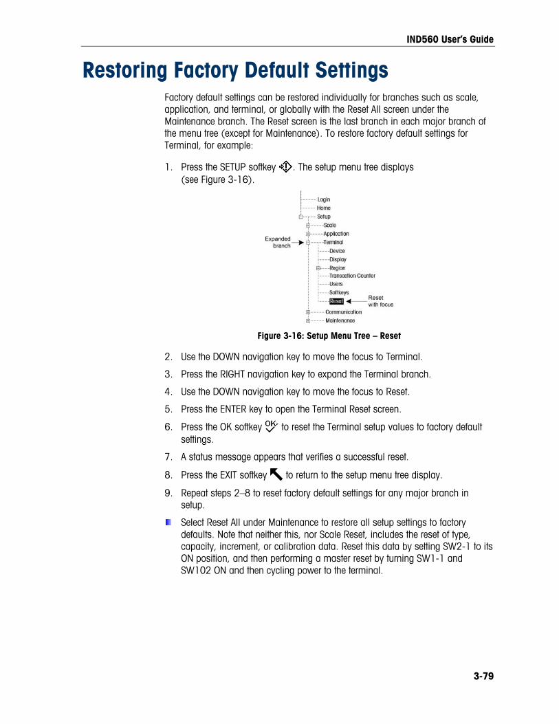
IND560 User’s Guide
Restoring Factory Default Settings Factory default settings can be restored individually for branches such as scale, application, and terminal, or globally with the Reset All screen under the Maintenance branch. The Reset screen is the last branch in each major branch of the menu tree (except for Maintenance). To restore factory default settings for Terminal, for example:
1. Press the SETUP softkey . The setup menu tree displays (see Figure 3-16).
Figure 3-16: Setup Menu Tree – Reset
2. Use the DOWN navigation key to move the focus to Terminal.
3. Press the RIGHT navigation key to expand the Terminal branch.
4. Use the DOWN navigation key to move the focus to Reset.
5. Press the ENTER key to open the Terminal Reset screen.
6. Press the OK softkey to reset the Terminal setup values to factory default settings.
7. A status message appears that verifies a successful reset.
8. Press the EXIT softkey to return to the setup menu tree display.
9. Repeat steps 2–8 to reset factory default settings for any major branch in setup.
Select Reset All under Maintenance to restore all setup settings to factory defaults. Note that neither this, nor Scale Reset, includes the reset of type, capacity, increment, or calibration data. Reset this data by setting SW2-1 to its ON position, and then performing a master reset by turning SW1-1 and SW102 ON and then cycling power to the terminal.
3-79

Chapter 4.0 Service and Maintenance
The IND560 terminal is designed to provide years of dependable operation. However, METTLER TOLEDO recommends that – as with any industrial measurement equipment – the IND560 terminal and the connected scale system be serviced periodically. Timely, factory-specified maintenance and calibration by a METTLER TOLEDO service technician will ensure and document accurate and dependable performance to specifications.
This chapter covers
• Cleaning and Maintenance
• Service
• Upgrading Firmware
• USB Backup and Restore
• Changing Screensaver graphic
Cleaning and Maintenance • Troubleshooting
• External Diagnostics (Web Server) Clean the IND560 terminal’s keypad and cover with a clean, soft cloth
that has been dampened with a mild glass cleaner. Do not use any type of industrial solvent such as toluene or isopropanol (IPA) that could damage the terminal’s finish. Do not spray cleaner directly on the terminal.
Regular maintenance inspections and calibration by a qualified service technician are recommended. The IND560 is a rugged stainless steel enclosed instrument; however, the font panel is a vinyl covering over sensitive electronic switches and a lighted display. Care should be taken to avoid any punctures to this surface or any vibrations or shocks to the instrument. Should the front panel become punctured, ensure that steps are taken to prevent dust and moisture from entering the unit until the terminal can be repaired.
Service Only qualified personnel should perform installation, programming, and service. Please contact a local METTLER TOLEDO representative for assistance.
In general, once the IND560 is installed, programmed, and calibrated for a given application, only routine calibration service is required.
WARNING ONLY PERMIT QUALIFIED PERSONNEL TO SERVICE THE TERMINAL. EXERCISE CARE WHEN MAKING CHECKS, TESTS AND ADJUSTMENTS THAT MUST BE MADE WITH POWER ON. FAILING TO OBSERVE THESE PRECAUTIONS CAN RESULT IN BODILY HARM AND/OR PROPERTY DAMAGE.
4-1

IND560 User’s Guide
WARNING! IF THE KEYBOARD, DISPLAY LENS OR ENCLOSURE IS DAMAGED ON A DIVISION 2 APPROVED OR CATEGORY 3 MARKED IND560 PANEL-MOUNT OR HARSH TERMINAL THAT IS USED IN A DIVISION 2 OR ZONE 2/22 AREA, THE DEFECTIVE COMPONENT MUST BE REPAIRED IMMEDIATELY. REMOVE AC POWER IMMEDIATELY AND DO NOT REAPPLY AC POWER UNTIL THE DISPLAY LENS, KEYBOARD OR ENCLOSURE HAS BEEN REPAIRED OR REPLACED BY QUALIFIED SERVICE PERSONNEL. FAILURE TO DO SO COULD RESULT IN BODILY HARM AND/OR PROPERTY DAMAGE.
Upgrading Firmware Upgrading from Version 1.xx Firmware to Version 2.xx, 3.xx or 4.xx The upgrade from version 1.xx to v2.xx, v3.xx or v4.xx of the IND560 firmware requires the installation of new bootcode in addition to the firmware. The new bootcode should be flashed before the new firmware.
Upgrading from v2.xx firmware to v3.xx or v4.xx firmware or upgrading from v3.xx to v4.xx does not require a new bootcode. v2.xx, v3.xx and v4.xx share the same bootcode (IND560BootV2.00.dat).
There are two ways to install an upgraded version of the IND560 firmware. The preferred method uses the PC-based InSite™ configuration tool , but it is also possible ot do so without a computer, using a USB flash memory drive connected to the options USB port
Performing an Upgrade with InSite The InSite program is used to flash new terminal firmware through the COM1 serial port or the optional Ethernet port. The firmware update and the InSite configuration tool program must be saved on a PC that will be connected to the terminal for firmware flashing.
Implement the following steps to prepare the terminal for firmware flashing using the InSite configuration tool:
Access the InSite tool by double-clicking on its icon – .
The new firmware might generate a checksum error on restart, which can be cleared by pressing ENTER on the terminal’s keypad. This performs a Master Reset. Therefore, it is important to use InSite™ to back up the current configuration and table data before performing the upgrade.
1. Remove power from the terminal.
4-2

IND560 User’s Guide
4-3
2. Open the terminal enclosure as specified in Appendix A, Installation, Opening the Enclosure.
3. Set the SW1-1 switch to OFF (if not already in the OFF position) and the SW1-2 switch to ON. (See Appendix A, Installation for switch locations.)
Setting SW2-1 to ON will correctly prepare COM1 for connection to InSite by temporarily bypassing all existing COM1 setup parameters and connections.
4. Apply power to the terminal. The first firmware download screen displays, with the message Update Code, Mode Select.
5. If Ethernet will be used for connection, press and hold the ENTER key for five seconds as soon as the first download screen displays. The Ethernet download screen displays.
6. Using the navigation keys and the numeric keypad, change the IP address and/or the subnet mask settings if required. (These settings will be saved in the Ethernet setup on the terminal when the download is complete.)
7. After stepping through the last subnet mask values, the bottom of the IND560 screen will display “Please download file”. The terminal is now ready to have the InSite program flash the new firmware.
8. If the COM1 serial port will be used for connection, do not press ENTER when the initial download screen is shown. After a few seconds, the Serial port download screen displays, which will list parameters for the serial port download (these parameters cannot be changed). The serial port on the PC must be programmed to match these parameters. This is done automatically in the InSite program. Parameters listed include:
Baud Rate: 115200
Data Bits: 8
Parity Bit: None
Stop Bits: 1
Flow Control: None
9. Connect the Ethernet or serial port cable from the PC that contains the firmware update and the InSite configuration tool program to the IND560 terminal. (See Appendix A, Installation for connection locations.) The terminal is now ready for firmware flashing.
10. Refer to the instructions/help provided with the InSite configuration tool program for procedures required to complete firmware flashing.
11. When the firmware download process is complete, disconnect the serial or Ethernet cable, return switch SW1-1 to its original position (if it was changed) and turn the SW1-2 switch to OFF.
12. Close the terminal enclosure.
To eliminate potential memory errors, it is recommended that a Master Reset be performed after flashing new firmware. This procedure is described later in this chapter.

IND560 User’s Guide
Performing the Upgrade via USB The USB upgrade option can only be used in terminals with v4.0x firmware or higher. In general, USB drives that are USB 2.0 certified and 1.1 compatible will be supported by the IND560.
To perform an upgrade from a USB drive, the terminal must be powered up with the USB drive attached.
To perform an upgrade with via the USB port:
1. The firmware to be downloaded to the IND560 must be saved in a specifically named file folder on the root directory of a USB drive. The firmware file must be named upgrade.dat
• See Table 4-1 for required USB file folder names 2. If required, open the terminal enclosure as specified in Appendix A, Installation,
Opening the Enclosure.
3. Connect the USB drive to the USB port installed in the IND560.
4. Go to Maintenance/Run/Diagnostics/Install S/W Upgrade
5. At the Install S/W Upgrade screen, when status is “Ready”, press the START softkey to initiate the upgrade. The IND560 will indicate that it is working.
6. Upon completion of the upgrade, the IND560 will display an “Update Successful” pop up message. You will now need to press the ENTER key to clear the message. This will initiate a power cycle.
File Locations on USB Drive The software upgrade, backup and restore functions use the following folders on the USB drive:
Table 4-1: USB File Folder Names
File Type Location on USB Drive
TaskExpert files TEBK1/*.*
Configuration and calibration files CFGBK1/*.dmt
Software upgrade files Upgrade/upgrade.dat
Each file type must be placed in the appropriate USB file folder for the software upgrade and restore from USB functions to carry out successfully.
Backup and Restore with USB To perform these procedures, the terminal must be powered up with the USB
drive attached.
The IND560 also allows certain data to be backed up to a USB memory stick and restored from a USB memory stick. This data includes:
4-4

IND560 User’s Guide
• Configuration Data (setup) and Calibration Data
• Task Expert Files This data can later be restored to the terminal via the USB drive and USB port, or copied to additional terminals in a replication process. This permits the restoration of setup should a main PCB require replacement, for example, and it allows for the easy creation of functionally identical terminals. Refer to Table 4-1 for a list of required USB file folder names.
Backup Backup to USB can be performed by users with any access level, and may be carried out even when the indicator is metrologically sealed.
The following four files are the backup files for all of the setup and configuration parameters in the IND560:
• bkram.dmt
• flash.dmt
• e2prom1.dmt
• e2prom2.dmt 1. Connect a USB (flash) memory device to the IND560 USB port. The optional
Ethernet/USB/COM3 board must be installed.
2. Access Setup/Maintenance/Run/Diagnostics/Backup to USB. The screen shown in Figure 4-1 will appear.
Figure 4-1: Backup to USB
3. Select the information to be backed up to the USB drive. Selections are:
• Config. & Cal. (Configuration & Calibration)
• TE Files only (Task Expert files only)
4. Press the START softkey. The terminal will show “Working, Please wait” as the backup attempt is made.
If no external USB drive is connected, the START softkey will not function.
5. A successful backup will show “Success”, and the operator will be prompted to press the ENTER key. A failed backup will show “Failure”. Press ENTER to acknowledge.
4-5
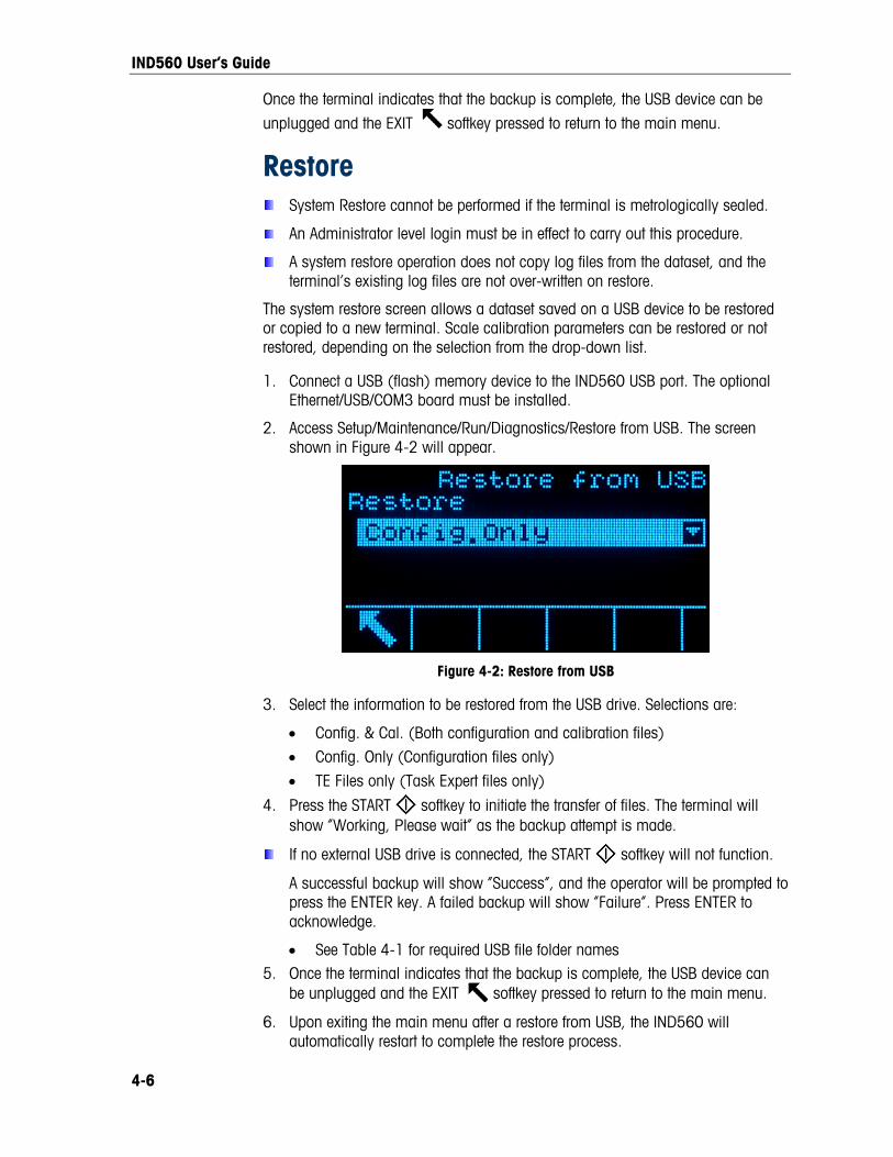
IND560 User’s Guide
Once the terminal indicates that the backup is complete, the USB device can be
unplugged and the EXIT softkey pressed to return to the main menu.
Restore System Restore cannot be performed if the terminal is metrologically sealed.
An Administrator level login must be in effect to carry out this procedure.
A system restore operation does not copy log files from the dataset, and the terminal’s existing log files are not over-written on restore.
The system restore screen allows a dataset saved on a USB device to be restored or copied to a new terminal. Scale calibration parameters can be restored or not restored, depending on the selection from the drop-down list.
1. Connect a USB (flash) memory device to the IND560 USB port. The optional Ethernet/USB/COM3 board must be installed.
2. Access Setup/Maintenance/Run/Diagnostics/Restore from USB. The screen shown in Figure 4-2 will appear.
Figure 4-2: Restore from USB
3. Select the information to be restored from the USB drive. Selections are:
• Config. & Cal. (Both configuration and calibration files)
• Config. Only (Configuration files only)
• TE Files only (Task Expert files only)
4. Press the START softkey to initiate the transfer of files. The terminal will show “Working, Please wait” as the backup attempt is made.
If no external USB drive is connected, the START softkey will not function.
A successful backup will show “Success”, and the operator will be prompted to press the ENTER key. A failed backup will show “Failure”. Press ENTER to acknowledge.
• See Table 4-1 for required USB file folder names 5. Once the terminal indicates that the backup is complete, the USB device can
be unplugged and the EXIT softkey pressed to return to the main menu.
6. Upon exiting the main menu after a restore from USB, the IND560 will automatically restart to complete the restore process.
4-6

IND560 User’s Guide
Changing Screen Saver Graphic The graphic used by the IND560 as a screen saver can be changed by downloading a replacement file to the terminal.
Screen Saver Graphic Specification The screen saver graphic is a bitmap file that should measure no more than 35 pixels wide and 35 pixels high. The file must be named saver.bmp.
Installing New Graphic The screen saver graphic can be installed on the IND560 by making an ftp connection to the terminal via EtherNet, logging on as an administrator (with write privileges), and copying the file to ram:\saver.bmp. Refer to the ftp section of Appendix D, Communications, for further details.
Display Messages If, on power-up, the terminal finds that the hardware application key status has changed, a fault message (Figure 4-3) will display. For instance, if the Fill-560 hardware key was added to a standard unit, the fault would be displayed at power up.
Figure 4-3: Application Key Fault Message
Even though the ENTER graphic is shown, the ENTER key does not function. Two responses to this error are possible:
• If the hardware key status was not changed on purpose, turn power off and determine what caused the status to change. Fix the problem and apply power again. The terminal will retest the hardware key status.
• If the hardware key status was changed on purpose by adding or removing a key, perform a manual Master Reset – refer to Master Reset under Trouble-shooting, below.
Note: Back up the terminal’s current setup parameters before the hardware key status is changed. The original setup can then be downloaded to the terminal after the Master Reset has been performed.
4-7

IND560 User’s Guide
4-8
Setting a Custom Language The IND560 terminal allows custom languages to be selected for display messages.
The procedure below assumes that a properly-configured text file, named either cust.txt or cust2.txt contains a complete set of display messages in the custom language. Table 4-1 shows the languages currently available. Contact your METTLER TOLEDO technical support provider to obtain custom files for download to the terminal.
Table 4-1: Custom Languages
Text File Available Language/s
cust.txt Polish, Portuguese
cust2.txt Russian
To set the custom language:
1. Make an ftp connection to the terminal.
2. Copy the cust.txt or cust2.txt file to the root directory of the IND560 (Flash2).
3. On the terminal, access Setup > Terminal > Region > Languages.
4. In the Display Messages field dropdown list, select Custom or Custom2 as appropriate.
5. Exit setup. Messages on the terminal’s display will now appear in the custom language.
Troubleshooting Troubleshooting activities for the IND560 include:
• AC power test
• Power supply voltage test and Load Cell and IDNet power
• Battery test
• Internal Diagnostic Testing
• RS-232 Serial Output Voltage Test
• Master Reset

IND560 User’s Guide
AC Power Test If the display is blank or if intermittent problems are occurring, the condition of the AC power source should be checked. Use a multi-meter to check the AC input power. Input power must be within −15% to +10% of the standard 100–240 voltage range.
Begin by checking the AC power at the source. If no AC power is present, have a qualified electrician at the site restore power at the source. After power is restored, test the IND560 for correct operation.
If there is AC voltage present at the source, check for the same voltage between pin 1 (brown wire) and pin 2 (blue wire) on the Power Supply harness to the Main PCB as shown in Figure 4-4.
Pin 1 (brown)
Pin 2 (blue)
Pin 4 (black)
Pin 5 (red)
Pin 6 (white)
Figure 4-4: Pin Locations on the Power Supply Harness
If no AC voltage is present, the fuse on the Main PCB has probably been blown. This fuse is designed to protect the source wiring in case of an internal power supply short. If the fuse is blown, the IND560 power supply is probably defective. To check this, replace the fuse and see if it blows again. If it does, replace the IND560 power supply.
If AC power is present on the blue and brown wires, the power supply should be checked next.
Power Supply Voltage Test The power supply provides 5 VDC to both the Main PCB and the Display PCB, and 12 VDC to the Main PCB. Verify the 12 VDC voltage is between 11 and 19 volts when measured from Pin 6 (+V) to Pin 4 (Ground). Verify the 5 VDC voltage is between 4.9 and 5.1 volts when measured from Pin 5 (+V) to Pin 4 (Ground). If either of the voltages is absent or outside the specified range, replace the Power Supply PCB. See Figure 4-4, above, for the locations of Pins 4, 5, and 6 on the Power Supply harness.
4-9

IND560 User’s Guide
Load Cell and IDNet Power The power to operate an IDNet base and the excitation voltage for analog load cells are both developed from the 12 VDC supply. This supply has short-circuit protection built into the power supply board. If the IDNet base or analog load cell circuit draws too much current (for example, when shorted to ground), the 12 VDC supply will shut itself off. After the protection circuit is triggered, the terminal must be powered down for at least 30 seconds before reapplying power. After this time, the short-circuit protection circuit will reset and the 12 VDC supply will be available again.
If the 12 VDC supply measures 0 VDC during the voltage check, power the terminal down, disconnect the IDNet base or analog load cell(s), wait 30 seconds, then reapply power. If the 12 VDC supply is now OK, check the IDNet base or analog load cell(s) for defects.
Battery Test If setup parameters change uncontrollably or programming is lost, check the BRAM battery voltage. Battery voltage is tested at the battery assembly on the Main PCB. The battery and power connector are shown in Figure 4-5.
Battery (+)
Pin 4 (grd.)
Figure 4-5: Battery Test
Use a Volt-Ohm meter to measure voltage between the top of the battery (+) and pin 4 (ground) of the power supply connector with the AC power disconnected. This measurement should be approximately 3.0 VDC. Replace the Main PCB if the measured voltage is below 2.5 VDC.
Internal Diagnostic Testing The IND560 provides several internal diagnostic tests that are accessible in setup mode. Press the SETUP softkey to view the setup menu tree. Use the DOWN navigation key to scroll down the menu tree to Maintenance. Press the RIGHT navigation key to expand the menu tree selections for Maintenance. Scroll down and expand Run. Scroll down and expand Diagnostics. Available diagnostic setup screens include:
• Display Test—Displays an alternate off/on dot block pattern when accessed. After the alternate off/on cycle, the display will return to the menu tree.
4-10

IND560 User’s Guide
• Keyboard Test—Enables testing of the keyboard. Each key that is pressed will be shown on the display. When testing is complete, press the EXIT softkey to return to the menu tree.
• Scale
• Load Cell Output—Displays the current load cell output (active weight) for the scale. This is useful to determine exactly how many counts the analog section is outputting and is not available with IDNet bases.
• Calibration Values—Displays the current calibration values for the scale. If these values are recorded after a scale calibration, and the Main PCB is replaced in the future, the calibration values can be manually entered here to “transfer” the previous calibration to the new Main PCB. This is not available with IDNet bases.
• Statistics—Displays statistical information for the scale such as the total number of weighments, the number of scale overloads, the peak weight weighed on the scale, total number of zero commands and failed zero commands. These are very helpful when diagnosing scale problems.
• Serial Test—Enables testing of the transmit and receive functions on the serial (COM) ports. Select the COM port to be tested using the selection box for Com Port. Only those ports installed are available for testing.
• Press the START softkey and a data string is output repeatedly approximately once every three seconds. The data is: [Testing COMx: nn] where “x” is the COM port and “nn” is an incrementing value beginning at 00 and continuing to 99. Each transmission increments this number by one.
• If a jumper wire is placed between the transmit and the receive terminals (Figure 4-6) on the port being tested, the same data string that is transmitted displays as the receiving field.
Figure 4-6: Jumper Wire Between Transmit and Receive Terminals
• If another device is connected to the receiving port, any ASCII data received displays in the receiving field.
• To stop the serial port test, press the STOP softkey .
• Discrete I/O Test—Provides a view of the status of the discrete inputs and allows enabling or disabling of the discrete outputs for diagnostic purposes. Expand the Discrete I/O branch by pressing the RIGHT navigation key. Choose
4-11

IND560 User’s Guide
if the test will be performed on the local (internal) discrete I/O option or one of the remote ARM100 modules. Press ENTER when that branch is highlighted.
There will be a warning shown next to remind the tester that the outputs can be turned on manually during this test so any control power to the discrete outputs should be removed.
WARNING THE DISCRETE OUTPUTS OF THE IND560 TERMINAL WILL BE MANUALLY ENABLED DURING THIS TEST. REMOVE OUTPUT CONTROL POWER SO EXTERNAL EQUIPMENT WILL NOT BE ENERGIZED BY MISTAKE. EXERCISE CARE WHEN MAKING CHECKS, TESTS AND ADJUSTMENTS THAT MUST BE MADE WITH POWER ON. FAILING TO OBSERVE THESE PRECAUTIONS CAN RESULT IN BODILY HARM AND/OR PROPERTY DAMAGE.
When viewing the test screen, the input status will be shown at the top of the display and the output status will be shown at the bottom of the display Figure 4-7). Focus is shown on Output #1 first.
Figure 4-7: Discrete I/O Test Screen
Focus can be moved to any of the other outputs by using the RIGHT and LEFT navigation keys. The two softkeys at the bottom of the page will either enable
or disable the highlighted output.
Note that when the Discrete I/O Test screen is exited, all outputs will be turned off again.
• Network Test—Enables testing of the Ethernet programming/hardware/firmware in the terminal. The following tests are run during this diagnostic process:
• TCP/IP Stack
• This IP Address
• Gateway address
Each step will indicate “Testing” during the test then indicate a Pass or Timeout status. If the status is shown as Timeout, it indicates that the IP address or gateway address has not been programmed in the terminal (see Chapter 3.0, Configuration, Communication, Network for information on entering the IP and gateway addresses.
4-12

IND560 User’s Guide
RS-232 Serial Output Voltage Test If tests of the sending and receiving functions on the serial (COM) ports test fails, use the following procedure to determine whether the RS-232 serial port is operational:
1. Remove power from the IND560 terminal and the printer.
2. Disconnect the data cable from the printer.
3. Set the voltmeter to read 20 VDC.
4. Connect the red lead to the transmit terminal of the COM port and connect the black lead to the ground terminal of the COM port.
5. Apply power to the IND560. The meter should read as follows:
• Demand mode—The meter should read a stable value (without fluctuation) between −5 and −15 VDC.
• Continuous mode—The meter should fluctuate continuously within the range −10 to +10 VDC. The actual values and degree of fluctuation observed will depend on the type and sensitivity of the meter used. The constant fluctuation on the meter display indicates that the scale/terminal is transmitting information.
To test Demand baud rates, press the PRINT key . The display should fluctuate as for continuous mode for the duration of the transmission, then become stable again. This fluctuation indicates the terminal has transmitted data.
When measuring higher baud rates in Demand mode, the meter display will fluctuate less, and for a shorter period of time.
Master Reset A hardware master reset is provided that sets all IND560 terminal settings to the factory default settings (refer to Appendix B, Default Settings).
The master reset typically is performed under these circumstances:
• When a software configuration problem arises that cannot be resolved without starting from the factory default settings.
• When security is enabled to protect setup, and the password is lost.
• After a firmware upgrade is performed.
• After a hardware key is installed or removed.
To initiate a master reset, perform the following steps:
1. Remove AC power.
2. Note the position of switches SW1-1 and SW1-2.
4-13

IND560 User’s Guide
3. Place both switches SW1-1 and SW1-2 in the ON position, as shown in Figure 4-8.
SW1
Figure 4-8: Switches SW1-1 and SW1-2
The position of SW2-1 (indicated in Figure 4-9) determines whether metrologically significant EEPROM (scale, calibration) data is reset when a master reset is performed. SW2-1 must be set to ON to reset EEPROM data. If SW2-1 is set to OFF, EEPROM data will not be affected by the master reset.
Figure 4-9: Location of Switch SW2-1
4. Apply AC power. A warning message displays asking if all values should be reset to factory defaults.
5. Press ENTER to perform a master reset. When the reset is complete, a confirmation message displays.
6. Remove AC power.
7. Return SW1-1 and SW1-2 (and, if they were changed, SW2-1 and SW2-2) to their original positions, noted in step 2.
8. Reapply AC power.
OR
If a master reset is not desired:
1. Do not press ENTER.
2. Remove AC power.
3. Reset switches SW1-1 and SW1-2 (and, if they were changed, SW2-1 and SW2-2) to their original positions.
4. Reapply AC power.
4-14

IND560 User’s Guide
External Diagnostics The IND560 includes a built-in web server utility that provides valuable tools for examining the operation of the terminal, its installed options and software. Information available in the Web Server includes:
• System hardware and software configuration
• Resource utilization
• Scale statistics and data
Web Help can also be used for the following functions:
• Reading shared data variables, viewed either statically or dynamically
• Writing shared data values
• Remote terminal reset
The Web Server is accessed with a web browser via an Ethernet connection. Access to the Terminal is provided by using its IP address. An IP address can be manually assigned, or assigned automatically by the network, depending on how DHCP is configured in setup at Communication > Network > Ethernet. If DHCP client is enabled, once the terminal is connected to the Ethernet its IP address will appear in the Ethernet configuration screen.
After an IP address for the IND 560 has been entered or automatically assigned using DHCP, record the address and enter it as the URL in the browser.
If the connection was successful, the Web Server home page (Figure 4-10) is displayed.
Home Page When the Web Server is first accessed, the Home page shown in Figure 4-10 appears in the browser window.
Figure 4-10: Web Server Home Screen
Click the links on this page to visit the respective views, each of which is detailed in the following sections.
4-15

IND560 User’s Guide
At the bottom of each page accessed, a HOME button is shown which returns the view to the Home page seen in Figure 4-10 when pressed.
View Pages
Help File A help file, accessible from each page via the help button explains the full range of the utility’s features. Refer to this file for a full explanation of each of the items visible in each page.
Figure 4-11 shows a portion of the help file.
Figure 4-11: Help File
At the bottom of the Help page, a CLOSE WINDOW button allows the user to close this browser window without exiting the Web Server utility.
4-16

IND560 User’s Guide
System Information The system information page (Figure 4-12) provides information about asset information, installed component part numbers, software versions and serial numbers, and installed application software. The Channel Software column is not filled unless the terminal is using an IDNet scale base.
Figure 4-12: System Information Page
Resource Utilization The resource utilization page (Figure 4-13) gives a snapshot of the current status of the terminal, including power on time and information about the various types of memory used by the IND560.
Figure 4-13: Resource Utilization Page
4-17

IND560 User’s Guide
Scale Statistics The scale statistics page (Figure 4-14) shows a variety of data for the scale.
Figure 4-14: Scale Statistics Page
4-18

IND560 User’s Guide
Scale Data The scale data page (Figure 4-15) shows information, including current configuration and calibration values, for the scale. The signal quality display permits troubleshooting of the connection between the IND560 and load cells. When quality is poor, a red bar is displayed. A yellow bar indicates adequate quality, and green bar means the quality is good, as in the example below.
Figure 4-15: Scale Data Page
4-19

IND560 User’s Guide
Diagnostics & Maintenance Pages
Shared Data The shared data page (Figure 4-16) allows the user to request a display of current values for up to ten shared data variables at a time. Values are accessed by entering the shared data name in one of the fields at left. When the Save Changes button at bottom is clicked, the Name fields are saved and the Values refreshed. The button is in focus when a new entry has been made in a Name field.
Figure 4-16: Shared Data Page
To refresh the displayed values without changing any variable names, click on the Manual Refresh button.
Values may also be refreshed automatically, at one second intervals, by clicking on the Start button. Once Start is selected, the Stop button is in focus and can be clicked. The current status of this dynamic display (Stopped or Running) is shown in a field between the two buttons. Note that, as indicated on the page, Auto Refresh must be stopped before new shared data names can be entered.
For a complete list of available shared data names, refer to the IND560 Shared Data Manual. In the example shown in Figure 4-16, the shared data information displayed is as follows:
Table 4-4: Shared Data Information
Name Data Displayed Interpretation
wt0101 29.2 Current gross weight value
xp0117 5585 Cumulative power on time, in minutes
ce0104 1 Number of ranges defined for the scale
ce0123 400000 Encoder counts at the middle calibration value for the scale
ce0125 16 GEO code set in the Scale 2 calibration page
nt0102 172.18.49.120 Ethernet IP Address
wt0103 kg Primary units set in the scale calibration page
4-20

IND560 User’s Guide
When a string is longer than the data display width of 40 characters, the left/right scroll buttons may be used to move through the string to view all of it.
Write Shared Data To access the Write Shared Data page, login at the administrator level is required. When prompted, enter the administrator’s user name and password. The screen shown in Figure 4-17 will appear.
Figure 4-17: Write Shared Data Page
Enter the Shared Data name in the Name column at left, and the value to be written to it in the Value column, then click on the Write button. Four Shared Data variables can be modified at a time.
Reset Terminal To access the Reset Terminal page, login at the administrator level is required. When prompted, enter the administrator’s user name and password. The screen shown in Figure 4-18 will appear.
Figure 4-18: Reset Terminal Page
4-21

IND560 User’s Guide
4-22
From this screen, the terminal can be restarted (equivalent to cycling power) or reset to factory defaults (except for calibration settings, tables and log files), with results as detailed on-screen.
When a Master Reset is performed, the Terminal’s IP address will default to factory settings.

1
Appendix A Default Settings
Setup Defaults The following tables list the factory default settings and associated security levels for the IND560 terminal setup parameters.
Items noted with an asterisk (*) are not shown for IDNet scales. Items noted with two asterisks (**) are shown only for IDNet scales.
Setup Feature Default Value Security Access
Scale – Type
Name Scale 1 Maintenance
Scale Type
- Automatically determined to be Analog or IDNet - Remote is secondary option after load cell
interface is determined
Administrator
* Approval None Administrator
Scale – Capacity & Increment
Primary Units Kg Administrator
* # of Ranges 1 Administrator
* >|1|< 50 x 0.01 Administrator
* Blank Over Capacity 5 d Administrator
** x10 Always Disabled Administrator
Scale – Calibration
* Geo Code 16 Administrator
Base Serial Number [blank] Administrator
* Calibration Units Kg Administrator
* Linearity Adjust Disabled Administrator
* Analog Gain Jumper 3 mV/V Administrator
* Cell Capacity 50 Administrator
* Cell capacity Unit Kg Administrator
* Rate Cell Output 3 mV/v Administrator
* Estimated Preload 0 Administrator
* Estimated Preload Unit Kg Administrator

IND560 User’s Guide
2
Setup Feature Default Value Security Access
Scale – Zero – AZM & Display
* Auto Zero Gross Administrator
** Auto Zero Enabled Administrator
* Auto Zero Range 0.5 d Administrator
* Under Zero Blanking 5 d Administrator
Power up Restart Administrator
Scale – Zero – Ranges
* Power Up Zero Disabled Administrator
* Power Up Range + 0 % − 0 % Administrator
Pushbutton Zero Enabled Administrator
* Pushbutton Range + 2 % − 2 % Administrator
Scale – Tare – Types
Pushbutton Tare Enabled Maintenance
Keyboard Tare Enabled Maintenance
Net Sign Correction Disabled Maintenance
** Terminal Tare Disabled Maintenance
Scale – Tare – Auto Tare
Auto Tare Disabled Maintenance
Tare Threshold Weight 0 kg Maintenance
Reset Threshold Weight 0 kg Maintenance
Motion Check Enabled Maintenance
Scale – Tare – Auto Clear
Auto Clear Tare Disabled Maintenance
Clear Threshold Weight 0 kg Maintenance
Motion Check Enabled Maintenance
Clear After Print Disabled Maintenance
Clear With Zero Disabled Maintenance
Power Up Restart Maintenance
Scale – Units
Second Unit None Administrator
Third Unit None Administrator
Power Up Restart Administrator
Custom Factor 1 Administrator
Custom Name Cust Administrator
Custom Increment 0.1 Administrator

IND560 User’s Guide
3
Setup Feature Default Value Security Access
Scale – Rate
Weight Units None Maintenance
Time Units Seconds Maintenance
Measurement Period 1 Supervisor
Output Average 1 Supervisor
Scale – Filter
* Low Pass Frequency 2.0 Hz Maintenance
* Low Pass # of Poles 8 Maintenance
* Notch Filter Frequency 30 Hz Maintenance
* Stability Filter Disabled Maintenance
** Vibration Average Conditions Maintenance
** Weighing Process Universal Weighing Maintenance
Scale – Stability
* Motion Range 1 d Administrator
* No-motion Interval 0.3 seconds Administrator
** Stability 2 Administrator
Timeout 3 Maintenance
Scale – Log or Print
Minimum Wt. 0 kg Maintenance
Interlock Disabled Maintenance
Automatic Disabled Maintenance
Reset on Return, 0 kg Maintenance
Threshold Wt. 0 kg Maintenance
Motion Check Disabled Maintenance
Scale – MinWeigh
MinWeigh Disabled Supervisor
Uncertainty Uo 0 kg Supervisor
Uncertainty c 0 Supervisor
Tolerance 0.1 Supervisor
Safety Factor 1 Supervisor
MinWeigh Value 0 kg Supervisor
Application – Memory – Alibi
Alibi Memory Disabled Administrator

IND560 User’s Guide
4
Setup Feature Default Value Security Access
Application – Memory – Tare Table
Description Disabled Maintenance
Totalization None Maintenance
Records 01–25 Empty Supervisor
Application – Memory – Message Table
Records 01–99 Blank table with no values
listed Supervisor
Application – Memory – Target Table
Mode None Maintenance
Tolerance Type Weight Deviation Maintenance
Output Type Concurrent Maintenance
Records 01–25 Blank table with no values
listed Supervisor
Application – Operation – Target
Source Displayed Weight Maintenance
Latching Enabled Maintenance
Motion Check Disabled Supervisor
Application – Operation – Comparators
Source None Supervisor
Active < Supervisor
Description [blank] Supervisor
Limit 0 Supervisor
High Limit 0 Supervisor
Application – Operation – Totalization
Mode None Maintenance
Clear GT on Print Disabled Maintenance
Subtotal Disabled Maintenance
Clear ST on Print Disabled Maintenance
Convert Weight Enabled Maintenance
Application – Operation – ID
Mode None Maintenance
Threshold 0 Maintenance
Reset 0 Maintenance
Looping Disabled Maintenance
Application – Discrete I/O – Inputs
Discrete Inputs Blank table with no values
listed. Maintenance
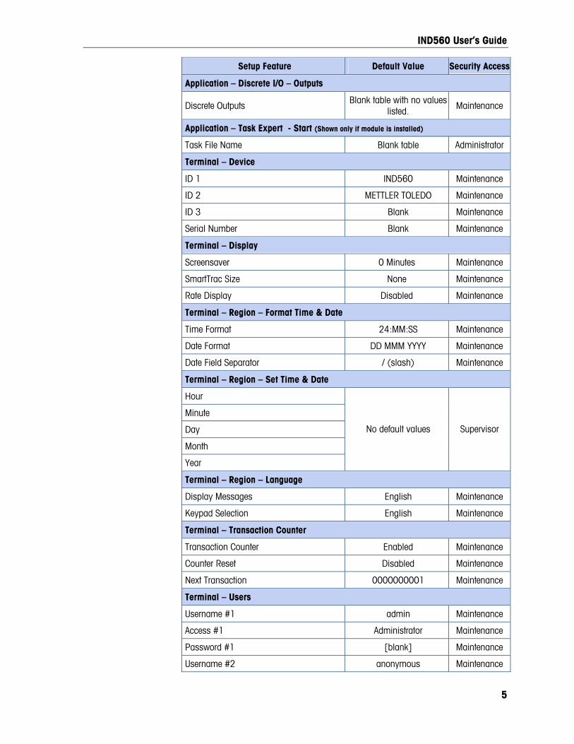
IND560 User’s Guide
5
Setup Feature Default Value Security Access
Application – Discrete I/O – Outputs
Discrete Outputs Blank table with no values
listed. Maintenance
Application – Task Expert - Start (Shown only if module is installed)
Task File Name Blank table Administrator
Terminal – Device
ID 1 IND560 Maintenance
ID 2 METTLER TOLEDO Maintenance
ID 3 Blank Maintenance
Serial Number Blank Maintenance
Terminal – Display
Screensaver 0 Minutes Maintenance
SmartTrac Size None Maintenance
Rate Display Disabled Maintenance
Terminal – Region – Format Time & Date
Time Format 24:MM:SS Maintenance
Date Format DD MMM YYYY Maintenance
Date Field Separator / (slash) Maintenance
Terminal – Region – Set Time & Date
Hour
Minute
Day
Month
Year
No default values Supervisor
Terminal – Region – Language
Display Messages English Maintenance
Keypad Selection English Maintenance
Terminal – Transaction Counter
Transaction Counter Enabled Maintenance
Counter Reset Disabled Maintenance
Next Transaction 0000000001 Maintenance
Terminal – Users
Username #1 admin Maintenance
Access #1 Administrator Maintenance
Password #1 [blank] Maintenance
Username #2 anonymous Maintenance
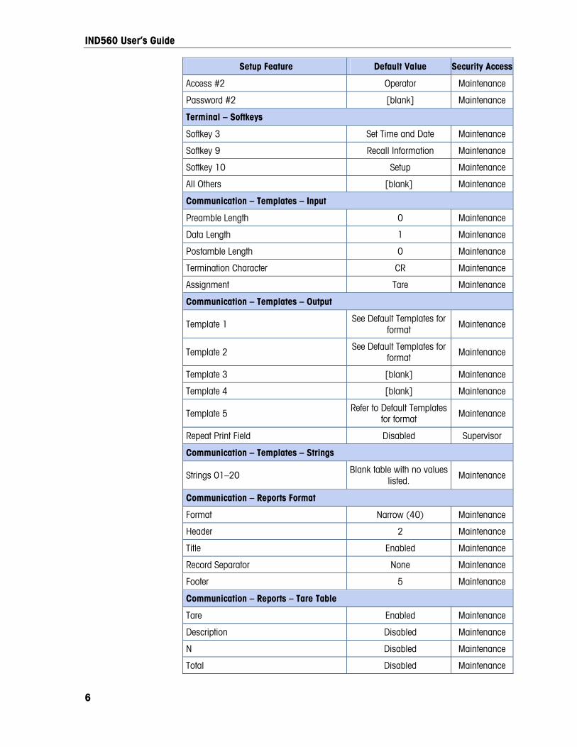
IND560 User’s Guide
6
Setup Feature Default Value Security Access
Access #2 Operator Maintenance
Password #2 [blank] Maintenance
Terminal – Softkeys
Softkey 3 Set Time and Date Maintenance
Softkey 9 Recall Information Maintenance
Softkey 10 Setup Maintenance
All Others [blank] Maintenance
Communication – Templates – Input
Preamble Length 0 Maintenance
Data Length 1 Maintenance
Postamble Length 0 Maintenance
Termination Character CR Maintenance
Assignment Tare Maintenance
Communication – Templates – Output
Template 1 See Default Templates for
format Maintenance
Template 2 See Default Templates for
format Maintenance
Template 3 [blank] Maintenance
Template 4 [blank] Maintenance
Template 5 Refer to Default Templates
for format Maintenance
Repeat Print Field Disabled Supervisor
Communication – Templates – Strings
Strings 01–20 Blank table with no values
listed. Maintenance
Communication – Reports Format
Format Narrow (40) Maintenance
Header 2 Maintenance
Title Enabled Maintenance
Record Separator None Maintenance
Footer 5 Maintenance
Communication – Reports – Tare Table
Tare Enabled Maintenance
Description Disabled Maintenance
N Disabled Maintenance
Total Disabled Maintenance

IND560 User’s Guide
7
Setup Feature Default Value Security Access
Communication – Reports – Target Table
Description Disabled Maintenance
Target Enabled Maintenance
+/- Tolerances Disabled Maintenance
Spill Disabled Maintenance
Fine Feed Disabled Maintenance
Communication – Connections (one default connection preconfigured)
Port COM1 Maintenance
Assignment Demand Maintenance
Trigger Scale Maintenance
Template Template 1 Maintenance
Communication – Serial – COM1
Baud 9600 Maintenance
Data Bits 8 Maintenance
Parity None Maintenance
Flow Control None Maintenance
Interface RS-232 Maintenance
Communication – Serial – COM2 (Shown only if Ethernet option detected)
Baud 9600 Maintenance
Data Bits 8 Maintenance
Parity None Maintenance
Flow Control None Maintenance
Interface RS-232 Maintenance
Communication – Serial – COM3 (Shown only if Ethernet option detected)
Baud 9600 Maintenance
Data Bits 8 Maintenance
Parity None Maintenance
Flow Control None Maintenance
Interface RS-232 Maintenance
Communication – Network – Ethernet (Shown only if Ethernet option detected)
MAC Address Unique value Maintenance
DHCP Client Disabled Maintenance
IP Address 192.168.0.1 Maintenance
Subnet Mask 255.255.255.0 Maintenance
Gateway Address 0.0.0.0 Maintenance

IND560 User’s Guide
8
Setup Feature Default Value Security Access
Communication – Network - Port (Shown only if Ethernet option detected)
Secondary Port # 0 Maintenance
Communication – Network – FTP (Shown only if Ethernet option detected.)
Username #1 admin Maintenance
Access #1 Administrator Maintenance
Password #1 admin Maintenance
Username #2 (not displayed) anonymous Maintenance
Access #2 (not displayed) Operator Maintenance
Password #2 (not displayed) [blank] Maintenance
Communication – Network – Email Alert–Parameters
SMTP Server IP 0.0.0.0 Maintenance
Sender Email Address [blank] Maintenance
Sender Name IND560 Maintenance
Subject Line Scale Cal. Alert Maintenance
Communication – Network – Email Alert–Recipients
Email Address [blank] Maintenance
Alert On None Maintenance
Communication – PLC – Analog Output (Shown only if Analog Output option detected)
Source Displayed Weight Administrator
Channel Scale Administrator
Zero Value 0 Administrator
Full Scale Value 50 Administrator
Communication – PLC – A-B RIO (Shown only if A-B RIO option detected)
Node Address Decimal, 1 Administrator
Start Quarter 1 Administrator
Last Rack Disabled Administrator
Data Rate 57600 Administrator
Block Transfer Disabled Administrator
Communication – PLC – DeviceNet (Shown only if DeviceNet option detected)
Node Address 63 Administrator
Data Rate 125k Administrator
Communication – PLC – PROFIBUS (Shown only if PROFIBUS option detected)
Node Address 1 Administrator
Shared Data Disabled Administrator
Communication – PLC – EtherNet/IP, Modbus TCP (Shown only if EtherNet / IP or Modbus TCP option detected)
Mac Address Assigned automatically Administrator

IND560 User’s Guide
9
Setup Feature Default Value Security Access
IP Address 192.168.0.1 Administrator
Subnet Mask 255.255.255.0 Administrator
Gateway Address 0.0.0.0 Administrator
Communication – PLC – Data Format (Shown only if PLC option detected)
Format Integer Administrator
Byte Order Word Swap Administrator
Message Slots 1 Administrator
Maintenance – Configure / View – Change Log
Change Log Disabled Administrator
Maintenance – Configure / View – Maintenance Log
Maintenance Log Disabled Maintenance
Maintenance – Configure / View – Calibration Management
Test Interval (Days) 0 Maintenance
Test Interval (Weighments) 0 Maintenance
On Expiration No Action Maintenance
Last Date Tested Current Date Maintenance
Next Test Date Current Date Maintenance
# of Weighments Left 0 Maintenance
Maintenance – Configure / View – Calibration Test
Test Load Units Kg Maintenance
Test Sequence Empty Maintenance
Maintenance – Run – Diagnostics – Scale – Calibration Values
Zero (Counts) 0 Administrator
Test Load #1 (Weight) 50 Administrator
Test Load #1 (Counts) 800,000 Administrator
Maintenance – Run – Diagnostics – Scale – Statistics
Weighments 0 N/A
Overloads 0 N/A
Peak Weight 0 kg N/A
Zero Commands 0 N/A
Zero Fail 0 N/A
Maintenance – Run – Backup to USB
Backup Config. & Calibration Operator
Maintenance – Run – Restore from USB
Restore Config. & Calibration Operator

IND560 User’s Guide
10
Default Templates Template 1
Element Data Format
1 wt0101 [ 010]
2 <sp> [ 001]
3 wt0103 [003 ]
4 CR/LF 1
5 ws0110 [ 010]
6 <sp> [ 001]
7 wt0103 [003 ]
8 ws0109 [002 ]
9 CR/LF 1
10 wt0102 [ 010]
11 <sp> [ 001]
12 wt0103 [003 ]
13 N [001 ]
14 CR/LF 2
15 -End-
Template 2
Element Data Format
1 cs0103 [021 ]
2 CR/LF 1
3 xd0104 [015 ]
4 CR/LF 1
5 xd0103 [015 ]
6 CR/LF 1
7 wt0101 [ 010]
8 <sp> [ 001]
9 wt0103 [003 ]
10 CR/LF 1
11 ws0110 [ 010]
12 <sp> [ 001]
13 wt0103 [003 ]
14 ws0109 [002 ]
15 CR/LF 1

IND560 User’s Guide
11
Template 2
Element Data Format
16 wt0102 [ 010]
17 <sp> [ 001]
18 wt0103 [003 ]
19 N [001 ]
20 CR/LF 2
21 - End -
Templates 3 and 4
Element Data Format
1 - End -
Template 5
Element Data Format
1 Totals Report [ 040 ]
2 CR/LF 1
3 xd0104 [020 ]
4 xd0103 [ 020]
5 CR/LF 1
6 Subtotal: - -
7 CR/LF 1
8 n = - -
9 tz0104 - -
10 tz0103 [ 030]
11 ce0103 [ 004 ]
12 CR/LF 1
13 Grand Total: - -
14 CR/LF 1
15 n = - -
16 tz0102 - -
17 tz0101 [ 030]
18 ce0103 [ 004 ]
19 CR/LF 1
20 - End -
Appendix B Communications
Serial Interface Parameters One standard and two optional serial ports are supported with the IND560 terminal. They are designated COM1 (standard port on the Main PCB), COM2 (optional), and COM3 (optional).
This Appendix covers
• Serial Interface Parameters
• Demand Output Mode
• Continuous Output Mode
• CTPZ
• SICS Protocol
• Remote Discrete I/O
COM1 provides RS-232, RS-422, and RS-485 interfaces. The RS-232 interface is a three-wire (TDX, RXD, and GND) with XON/XOFF flow-control capabilities (handshaking). This port can also be used for loading new IND560 firmware and to access the shared data server. The RS-422 interface is a four-wire interface designed for single point-to-point communication. The RS-485 connection is a two-wire interface but does not provide multi-drop communication with addressing. All interfaces can be output simultaneously; however, only one input can be used.
• ASCII Input
• Reports
• Shared Data Access
• Ethernet
• FTP
• Terminal Updates
Optional COM2 provides only RS-232. This interface is a three-wire connection with XON/XOFF handshaking capabilities.
Optional COM3 on the Ethernet/COM2/COM3 board provides RS-232, RS-422, and RS-485 interfaces. The RS-232 interface is a three-wire (TDX, RXD, and GND) with XON/XOFF flow-control capabilities (handshaking). The RS-422 interface is a four-wire interface designed for single point-to-point communication. The RS-485 connection is a two-wire interface but does not provide multi-drop communication with addressing. All interfaces can be output simultaneously; however, only one input can be used.
Optional COM3 on the Ethernet/USB/COM3 board provides RS-232 and RS-485. RS-422 is not available on COM3 of the Ethernet/USB/COM3 board.
Character framing is programmable in the setup mode. Framing can be:
• 1 start bit
• 7 or 8 ASCII data bits (selectable)
• 0 or 1 parity bit (none, even, or odd)
• 1 stop bit
The baud rate can be configured from 300 to 115.2K baud and a checksum character can also be configured for the standard continuous output string.
The IND560 terminal uses software handshaking to control data flow commonly referred to as XON/XOFF handshaking. When a receiving device (typically a printer)
B-1

IND560 User’s Guide
B-2
is getting information from an IND560 terminal and cannot receive any more in its buffer, it sends an ASCII XOFF (13h) telling the IND560 terminal to temporarily stop sending data until its buffer clears.
When the device can receive more data, it sends an ASCII XON (11h) telling the IND560 terminal to begin sending data again. This process can occur as often as required by a receiving device.
The XON/XOFF method is the only type of handshaking that is supported by the IND560 terminal.
The IND560 terminal supports two different modes of data output – demand and continuous.
Demand Output Mode The demand output mode transmits data only when the IND560 terminal receives a print request. Print requests are sent to the IND560 terminal when:
• The operator presses PRINT
• A discrete input selected as print is triggered
• An ASCII “P” is sent through a command input port
• Auto print is enabled and all conditions for auto print are met
• A PLC command to print is received
• The “Print” command shared data is triggered
When triggered, data is transmitted in a string programmed in the template editing portion of setup. Demand mode is used typically when sending data to a printer or PC on a transactional basis.
Custom Triggers There are three programmable custom triggers in the Connections section of setup that can be used to “trigger” a specific demand output. This could be used to provide a separate “Print” key (using a discrete input) that sends a specific template to a particular serial port, Ethernet port or the Eprint port. Using the custom triggers enables printing of different information to the same port or a different port based on which custom trigger is initiated. These custom triggers can provide great flexibility in configuring demand outputs.
A connection using a custom trigger is configured like a standard demand output except that Trigger 1, Trigger 2, or Trigger 3 is selected as the trigger instead of Scale. After making the connection, a custom trigger can be assigned to one of the discrete inputs to initiate the demand output. A custom trigger can also be initiated directly by a PLC command (refer to the IND560 Terminal PLC Interface Manual); by toggling one of the cp0101, cp0102, or cp0103 shared data variables (refer to the IND560 Shared Data Reference); or by assigning the trigger to one of the trigger softkeys (refer to the Connections section of Chapter 3, Configuration).

IND560 User’s Guide
B-3
Output Templates The IND560 provides five templates to define a custom string of data to be transmitted. A template can be used with a demand mode connection, a custom trigger connection or with a continuous template connection. In the setup of the terminal, a template is tied to an output connection so that when that connection is triggered, the selected template will be transmitted. The three default templates in the terminal from the factory are as follows:
Template 1 XX.XX kg XX.XX kg T XX.XX kg N
Template 2 Scale ID Current Time Current Date
XX.XX kg XX.XX kg T XX.XX kg N
Template 5 Totals Report Current Time Current Date Subtotal: n = XXX XXX.XX kg Grand Total: n = XXX XXXX.XX kg
Each template can store up to 1,000 bytes of data. Table B-1 defines how the 1,000 bytes are calculated. There is no warning if a template overflows this limit until the template is saved. At this time, any information over the 1,000-byte limit will be lost. The InSite program’s Template Editor feature does track the size of the template as it is being built and provides an appropriate warning if the limit is exceeded.
Table B-1: Calculation of Template Data Bytes
Print Field Space Used
IND560 Data Field 8 characters
Special Character 4 characters + code (2 or 3 characters depending on the character)
String Field String length + quantity (1 or 2)
Justify a Field 2 characters + justify letter (L, R, C) + space limit (1, 2, or 3 characters)
Zero Fill a Field 2 characters + Z + space limit (1, 2 or 3 characters)
Repeat Character 5 characters + number (1, 2 or 3 digits for number of times repeated)
Line end <CR><LF> 7 characters

IND560 User’s Guide
B-4
Template Example
The following example shows a customer ticket that has three template strings centered in a 40-character wide field, with an asterisk underline.
GROSSBERG TRUCKING CO. CHAMPAIGN, ILLINOIS DAILY WEIGHT TOTALS
****************************************
Use the information in Table B-2 to calculate how much of the template remains for field data.
Table B-2: Space Required for the Example Ticket Heading Information
Character Description Character Total
IND560 Field (String 1) 8 (IND560 shared data field)
Centered (Justify in 40-character field) 2 + 1 (letter C) + 2 (two digits for quantity 40)
CR (ASCII Carriage Return character) 2 + 1 (one digit for quantity 1)
LF (ASCII Line Feed character) 2 + 1 (one digit for quantity 1)
Total formatting characters required 19
Total space required (characters on each line) 25 + 19 + 19 = 63
ASCII (*) character 1 (ASCII character)
Repeat (*) 40 times 5 (repeat) + 2 (number of repeats)
CR 2 + 1 (one digit for quantity 1)
LF (ASCII Line Feed character) 2 + 1 (one digit for quantity 1)
Total space for line of asterisks 14
Grand total of characters (19 + 63 + 14) 96
Total characters remaining in this template (1,000 − 96)
904
For template space calculation:
Regardless of the number of characters in an IND560 terminal data field, a template uses only eight characters (the field code).
Justification uses four to six characters that are not used if the field remains unjustified.

IND560 User’s Guide
B-5
Repeat Print Notification
Output templates used for Demand printing transactions have the option of being designated with a “DUPLICATE” header or footer if they are generated through the Repeat Print softkey.
DUPLICATE GROSSBERG TRUCKING CO. CHAMPAIGN, ILLINOIS DAILY WEIGHT TOTALS
****************************************
or
GROSSBERG TRUCKING CO. CHAMPAIGN, ILLINOIS DAILY WEIGHT TOTALS
**************************************** DUPLICATE
Continuous Output Mode The continuous output mode of the IND560 can be used to continuously send weight data and scale status information to a remote device such as a PC or a remote display.
Standard Continuous Output Continuous Output can be assigned to COM1, COM2, COM3, Ethernet 1 or Eprint. Standard Continuous Output over Ethernet is addressed later in this Appendix. Checksum can be enabled or disabled on any of these ports with continuous output. A data string will be output approximately 20 times per second for baud rates above 4800 baud. If a baud rate below 4800 is selected, the output rate will be slower. At 300 baud, the output rate is only approximately 2 per second. The format is fixed, except for baud rate, parity, data flow (XON/XOFF), and interface type. The data consists of 17 or 18 bytes as shown in Table B-3.
Non-significant weight data and tare data digits are transmitted as spaces. The continuous output mode provides compatibility with METTLER TOLEDO products that require real-time weight data. Table B-3 shows continuous format output.
Table B-3: Continuous Output Format
Status2 Indicated Weight3 Tare Weight4
Character 1 2 3 4 5 6 7 8 9 10 11 12 13 14 15 16 17 18
Data STX1 SWA SWB SWC MSD - - - - LSD MSD - - - - LSD CR5 CHK6
Continuous Output Format Notes:
1. ASCII Start of Text character (02 hex), always transmitted.
2. Status words. Refer to Table B-4, Table B-5, and Table B-6 for details.

IND560 User’s Guide
B-6
3. Displayed weight. Either gross or net weight. Six digits, no decimal point or sign. Insignificant leading zeroes are replaced with spaces.
4. Tare weight. Six digits of tare weight data. No decimal point in field.
5. ASCII Carriage Return <CR> character (0D hex).
6. Checksum, transmitted only if enabled in setup. Checksum is used to detect errors in the transmission of data. Checksum is defined as the 2’s complement of the seven low order bits of the binary sum of all characters preceding the checksum character, including the <STX> and <CR> characters.
Table B-4, Table B-5, and Table B-6 detail the standard status bytes for standard continuous output.
Table B-4: Status Word A Bit Definitions
Bits 2, 1, and 0
2 1 0 Decimal Point Location
0 0 0 XXXXX00
0 0 1 XXXXX0
0 1 0 XXXXXX
0 1 1 XXXXX.X
1 0 0 XXXX.XX
1 0 1 XXX.XXX
1 1 0 XX.XXXX
1 1 1 X.XXXXX
Bits 4 and 3
4 3 Build Code
0 1 X1
1 0 X2
1 1 X5
Bit 5 Always = 1
Bit 6 Always = 0
Table B-5: Status Word B Bit Definitions
Status Bits Function
Bit 0 Gross = 0, Net = 1
Bit 1 Sign, Positive = 0, Negative = 1
Bit 2 Out of Range = 1 (Over capacity or Under Zero)
Bit 3 Motion = 1, Stable = 0
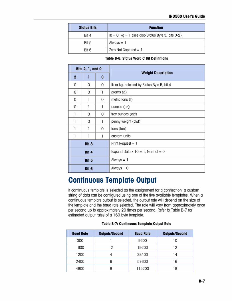
IND560 User’s Guide
B-7
Status Bits Function
Bit 4 lb = 0, kg = 1 (see also Status Byte 3, bits 0-2)
Bit 5 Always = 1
Bit 6 Zero Not Captured = 1
Table B-6: Status Word C Bit Definitions
Bits 2, 1, and 0
2 1 0 Weight Description
0 0 0 lb or kg, selected by Status Byte B, bit 4
0 0 1 grams (g)
0 1 0 metric tons (t)
0 1 1 ounces (oz)
1 0 0 troy ounces (ozt)
1 0 1 penny weight (dwt)
1 1 0 tons (ton)
1 1 1 custom units
Bit 3 Print Request = 1
Bit 4 Expand Data x 10 = 1, Normal = 0
Bit 5 Always = 1
Bit 6 Always = 0
Continuous Template Output If continuous template is selected as the assignment for a connection, a custom string of data can be configured using one of the five available templates. When a continuous template output is selected, the output rate will depend on the size of the template and the baud rate selected. The rate will vary from approximately once per second up to approximately 20 times per second. Refer to Table B-7 for estimated output rates of a 160 byte template.
Table B-7: Continuous Template Output Rate
Baud Rate Outputs/Second Baud Rate Outputs/Second
300 1 9600 10
600 2 19200 12
1200 4 38400 14
2400 6 57600 16
4800 8 115200 18
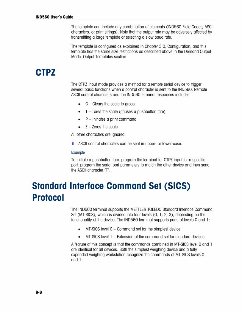
IND560 User’s Guide
B-8
The template can include any combination of elements (IND560 Field Codes, ASCII characters, or print strings). Note that the output rate may be adversely affected by transmitting a large template or selecting a slow baud rate.
The template is configured as explained in Chapter 3.0, Configuration, and this template has the same size restrictions as described above in the Demand Output Mode, Output Templates section.
CTPZ The CTPZ input mode provides a method for a remote serial device to trigger several basic functions when a control character is sent to the IND560. Remote ASCII control characters and the IND560 terminal responses include:
• C – Clears the scale to gross
• T – Tares the scale (causes a pushbutton tare)
• P – Initiates a print command
• Z – Zeros the scale
All other characters are ignored.
ASCII control characters can be sent in upper- or lower-case.
Example
To initiate a pushbutton tare, program the terminal for CTPZ input for a specific port, program the serial port parameters to match the other device and then send the ASCII character “T”.
Standard Interface Command Set (SICS) Protocol
The IND560 terminal supports the METTLER TOLEDO Standard Interface Command Set (MT-SICS), which is divided into four levels (0, 1, 2, 3), depending on the functionality of the device. The IND560 terminal supports parts of levels 0 and 1:
• MT-SICS level 0 – Command set for the simplest device.
• MT-SICS level 1 – Extension of the command set for standard devices.
A feature of this concept is that the commands combined in MT-SICS level 0 and 1 are identical for all devices. Both the simplest weighing device and a fully expanded weighing workstation recognize the commands of MT-SICS levels 0 and 1.

IND560 User’s Guide
B-9
Data Interface Configuration Setting of the interface such as baud rate, number of data bits, parity, handshake protocols and connector pin assignments are described in Chapter 3.0, Configuration.
Version Number of the MT-SICS Each level of the MT-SICS has its own version number, which can be requested with the command I1 from level 0. The IND560 supports:
• MT-SICS level 0, version 2.2x (except the ZI command)
• MT-SICS level 1, version 2.2x (except the D, DW and K commands)
Command Formats Each command received by the scale via the data interface is acknowledged by a response of the device to the transmitter. Commands and responses are data strings with a fixed format. Commands sent to the IND560 terminal comprise one or more characters of the ASCII character set. Enter commands only in uppercase.
The parameters of the command must be separated from one another and from the command name by a space (ASCII 32 dec., in the examples shown in this section, a space is represented as _ ).
Each command must be terminated by CR LF (ASCII 13 dec., 10 dec.)
The characters CR and LF, which can be inputted using the ENTER or RETURN key of most entry keypads, are not listed in this description. However, it is essential they be included for communication with the IND560 terminal.
Example
Command to tare the IND560 terminal:
“TA_20.00_lb” (The command terminator CR LF is not shown.)
Response Formats All responses sent by the IND560 terminal to the transmitter to acknowledge the received commands have one of the following formats:
Response with weight value
Response without weight value
Error message
Format of the Response with Weight Value A general description of the response with weight value as follows:

IND560 User’s Guide
ID – Response identification.
__ – Space (ASCII 32 dec.)
Status – Status of the IND560 terminal. See description of the commands and responses.
Weight Value – Weighing result, which is shown as a number with 10 digits, including sign directly in front of the first digit. The weight value appears right justified. Preceding zeroes are suppressed with the exception of the zero to the left of the decimal point.
Unit – Weight unit displayed.
CR – Carriage Return (ASCII 13 dec.)
LF – Line Feed (ASCII 10 dec.)
Comment – CR LF will not be shown in this description.
Example
Response with a stable weight value of 0.256 kg:
S _ S_ _ _ _ _ _ 0.256 _ kg
Format of the Response Without Weight Value A general description of the response without weight value is as follows:
ID – Response identification.
_ – Space (ASCII 32 dec.)
Status – Status of the IND560 terminal. See description of the commands and responses.
Parameters – Command-dependent response code.
CR – Carriage Return (ASCII 13 dec.)
LF – Line Feed (ASCII 10 dec.)
Comment – CR LF will not be shown in this description.
ID CR LF
B-10

IND560 User’s Guide
B-11
ID – Error Identification There are three different error messages. The identification always comprises two characters:
ES – Syntax error The IND560 terminal has not recognized the received command.
ET – Transmission error The scale has received a “faulty” command, such as a parity error.
EL – Logical error The IND560 terminal cannot execute the received command.
CR – Carriage return (ASCII 13 dec.)
LF – Line Feed (ASCII 10 dec.)
Comment – CR LF will not be shown in this description.
Tips for the Programmer Tips for programming the IND560 terminal SICS protocol include:
Command and Response Improve the dependability of application software by having the program evaluate the response of the IND560 terminal to a command. The response is the acknowledgment that the IND560 terminal has received the command.
Reset When establishing communication between the IND560 terminal and system, send a reset command to the IND560 terminal to enable a start from a determined state. When the IND560 terminal or system is switched on or off, faulty characters can be received or sent.
Quotation Marks (“ ”) Quotation marks included in the command responses are used to designate fields and will always be sent.
Commands and Responses MT-SICS Level 0 The IND560 terminal receives a command from the system computer and acknowledges the command with an appropriate response. The following sections contain a detailed description of the command set in alphabetical order with the associated responses. Commands and responses are closed with CR and LF. These termination characters are not shown in the following description, but they must always be entered with commands or sent with responses.

IND560 User’s Guide
B-12
The commands of MT-SICS level 0 are available with even the simplest devices, which support the METTLER TOLEDO Standard Interface Command Set. These include:
I0 Inquiry of all implemented MT-SICS commands
I1 Inquiry of MT-SICS level and MT-SICS versions
I2 Inquiry of balance data
I3 Inquiry of balance SW version and type definition number
I4 Inquiry of serial number
S Send stable weight value
SI Send weight value immediately
SIR Send weight value immediately and repeat
Z Zero
@ Reset (clear out serial buffer)
The following are detailed descriptions of these Level 0 commands:
I0 – INQUIRY OF ALL IMPLEMENTED MT-SICS COMMANDS
Command: I0 – Inquiry of all implemented MT-SICS commands
Response: I0 B 0 “I0” Level 0 “IO” command implemented
I0 B 0 “I1” Level 0 “I1” command implemented
I0 B 0 “I2” Level 0 “I2” command implemented
I0 B 0 “I3” Level 0 “I3” command implemented
I0 B 0 “I4” Level 0 “I4” command implemented
I0 B 0 “S” Level 0 “S” command implemented
I0 B 0 “SI” Level 0 “SI” command implemented
I0 B 0 “SIR” Level 0 “ SIR” command implemented
I0 B 0 “Z” Level 0 “Z” command implemented
I0 B 0 “@” Level 0 “@” command implemented
I0 B 1 “SR” Level 1 “SR” command implemented
I0 B 1 “T” Level 1 “T” command implemented
I0 B 1 “TA” Level 1 “TA” command implemented
I0 B 1 “TAC” Level 1 “TAC” command implemented
I0 B 1 “TI” Level 1 “TI” command implemented
Error Response I0 I - Cannot execute command at this time.

IND560 User’s Guide
B-13
I1 – INQUIRY OF MT-SICS LEVEL AND MT-SICS VERSIONS
Command: I1 – Inquiry of MT-SICS level and MT-SICS versions
Response: I 1 _ A _ “” _ “2.2x” _ “2.2x” _ “ ” _ “ ”
“” No Levels fully implemented
2.2x Level 0, version V2.2x
2.2x Level 1, version V2.2x
“” No MT-SICS 2 commands
“” No MT-SICS 3 commands
• Error Response I1 _ I – Command understood, not executable at present.
Comments
• In the case of the MT-SICS level, only fully implemented levels are listed. In this case, neither level 0 nor level 1 were fully implemented so the level is not specified.
• In the case of the MT-SICS version, all levels are specified even those only partially implemented.
I2 – INQUIRY OF DATA
Command: I2 – Inquiry of data.
Response: I 2 _ A _ “IND560 _ Standard _50.00 kg”
Response: I 2 _ A _ “IND560 _ 560Fill _50.00 kg”
• IND560 - Model number of terminal
• Standard - Basic model with no special application software
• 560Fill - Sent when an IND560-Fill is queried
• 50.00 kg - Capacity and primary unit of the base connected to the IND560
• Error Response I2 _ I – Command understood, not executable at present.
Comments
The number of characters of “text” depends on the application software and scale capacity.
I3 – INQUIRY OF SW VERSION AND TYPE DEFINITION NUMBER
Command I3: Inquiry of SW version number(s) and type definition number.
Response: I3 _ A _ “1.00”
1.00 – Firmware version of the IND560
Error Response I3 _ I – Command understood, not executable at present.

IND560 User’s Guide
B-14
Comment
The number of characters of “text” depends on the revision and device type.
I4 – INQUIRY OF SERIAL NUMBER
Command: I4 – Inquiry of serial number.
Response: I4 _ A _ “text”
Serial number as “text” (content of shared data xs0105 in IND560 terminal)
Error Response I4 _ I – Command understood, not executable at present.
Example
Command: I 4 – Inquiry of serial number
Response: I 4 _ A _ “123456-6GG”
Comments
The serial number response is the content of the terminal serial number as entered in the setup.
S – SEND STABLE WEIGHT VALUE
Command: S – Send the current stable net weight.
Response:
S _ S _ WeightValue _ Unit – Current stable weight value.
S _ I – Weight value is in the current displayed units.
S _ + – IND560 in overload range.
S _ - – IND560 in underload range.
Example
Command: S – Send a stable weight value.
Response: S _ S _ _ _ _ _ 100.00 _ kg. – The current, stable weight value is 100.00 kg.
Comments
The terminal will wait for up to 3 seconds after receiving an “S” command for no-motion. If motion does not settle within this time, the command is aborted.
SI – SEND WEIGHT VALUE IMMEDIATELY
Command: SI – Send the current net weight value regardless of scale stability.
Response:

IND560 User’s Guide
B-15
S _ S _ WeightValue _ Unit – Stable weight value.
S _ D _ WeightValue _ Unit – Non-stable (dynamic) weight value.
S _ I – Command not executable (scale currently executing another command).
S _ + – IND560 in overload range.
S _ - – IND560 in underload range.
Example
Command: SI – Send current weight value.
Response: S _ D _ _ _ _ _ 129.07 _ kg – The current weight value is unstable (dynamic) and is 129.07kg.
Comments
The response to the command SI is the last internal weight value (stable or dynamic) before receipt of the command SI.
Weight value is in the current displayed units.
SIR – SEND WEIGHT VALUE IMMEDIATELY AND REPEAT
Command: SIR – Send the net weight values repeatedly, regardless of scale stability.
Response:
S _ S _ WeightValue _ Unit – Stable weight value.
S _ D _ WeightValue _ Unit – Non-stable (dynamic) weight value.
S _ I – Command not executable (IND560 terminal is executing another command, such as taring).
S _ + – IND560 in overload range.
S _ - – IND560 in underload range.
Example
Command: SIR – Send current weight values at intervals.
Response:
S _ D _ _ _ _ _ 129.07 _ kg
S _ D _ _ _ _ _ 129.08 _ kg
S _ D _ _ _ _ _ 129.09 _ kg
S _ D _ _ _ _ _ 129.09 _ kg
S _ D _ _ _ _ _ 114.87 _ kg
. . . – The scale sends stable or non-stable weight values at intervals.

IND560 User’s Guide
B-16
Comments
SIR is overwritten and cancelled by the commands S, SI, SR, and @.
The number of weight values per second depends on the scale type and will vary from approximately 6 (older IDNet bases) to approximately 18 (analog bases).
Weight value is in the current displayed units.
Z – ZERO
Command: Z – Zero the scale.
Response:
Z _ A – The following then holds:
Scale is in gross mode
Zero setting performed, (stability criterion and zero setting range complied with).
Z _ I – Zero setting not performed (IND560 terminal is currently executing another command, such as taring, or timeout as stability was not reached.)
Z _ + – Upper limit of zero setting range exceeded.
Z _ - – Lower limit of zero setting range exceeded.
Example
Command: Z – Zero.
Response: Z _ A – Zero setting performed.
Comments
If enabled in setup a tare value will be cleared during zero setting.
The zero point determined during switching on is not influenced by this command (the measurement ranges remain unchanged).
The duration of the timeout is approximately one second.
@ – RESET
Command: @ – Reset the scale to the condition found after switching on, but without a zero setting being performed.
Response:
I 4 _ A _ “text” – Serial number of the scale, the scale is ready for operation.
Example
Command: @
Response: I4 _ A _ “123456-6GG” – The IND560 terminal is reset and sends the serial number.

IND560 User’s Guide
B-17
Comments
All commands awaiting responses are canceled.
The “reset” command is always executed.
A reset command received by the IND560 terminal during the calibration and test procedure cannot be processed.
Commands and Responses MT-SICS Level 1 The following commands of MT-SICS level 1 are available:
SR – Send weight value on weight change (Send and Repeat)
T – Taring
TA – Set tare value
TAC – Clear tare value
TI – Tare Immediately
SR – SEND WEIGHT VALUE ON WEIGHT CHANGE (SEND AND REPEAT)
Command: SR
S R _ PresetValue _ Unit – Send the current stable weight value and then continuously after every weight change greater or equal to the preset value a non-stable (dynamic) value followed by the next stable value, range = 1d to maximum load.
SR – If no preset value is entered, the weight change must be at least 12.5% of the last stable weight value, minimum = 30d.
Response:
S _ S _ WeightValue _ Unit – Current, stable weight value. Weight change.
S _ D _ WeightValue _ Unit – Dynamic weight value.
S _ S _ WeightValue _ Unit – Next stable weight value.
S _ I – Command not executable (the IND560 terminal is currently executing another command, such as taring, or timeout as stability was not reached.)
S _ L – Command understood, parameter wrong.
S _ + – IND560 in overload range.
S _ - – IND560 in underload range.
Example
Command: S R _ 0.50 _ kg – Send the current stable weight value followed by every load change > 0.50 kg.
Response:
S _ S _ _ _ _ _100.00 _ kg – Scale stable.

IND560 User’s Guide
B-18
S _ D _ _ _ _ _115.23 _ kg – More than 0.50 kg loaded.
S _ S _ _ _ _ _200.00 _ kg – Scale again stable.
Comments
SR is overwritten and cancelled by the commands S, SI, SIR, @ and hardware break.
If, following a non-stable (dynamic) weight value, stability has not been reached within the timeout interval, the response “S _ I “ is sent and then a non-stable weight value. Timeout then starts again form the beginning.
The preset value must be entered in the first unit that is the weight unit displayed after the IND560 terminal has been switched on.
T – Taring
Command: T – Tare a stable weight value
Response:
T_S_WeightValue_Unit – Taring performed. Stability criterion and taring range comply with settings. Current Tare weight value in current units is returned.
T_ I – Taring not performed (scale is executing another command, zero setting, or stability timeout reached.)
T_+ – Upper limit of taring range exceeded.
T_- – Lower limit of taring range exceeded.
Example
Command: T
Response: T _S _ _ _ _ _100.00_kg – The IND560 has accepted a tare value of 100.00 kg.
Comments
The new tare weight value overwrites tare memory.
The duration of the timeout depends on the scale type and its settings. If motion does not settle within this time, the command is aborted.
Clearing tare value: See command TAC
TA – INQUIRE/ENTER TARE VALUE
Command: TA – Inquiry of tare weight value
TA _ Tare Preset Value _ Unit – Entry of a tare value.
Response:
T A _ A _ TareWeightValue _ Unit – Current Tare weight value.
T A _ I – Current Tare weight value cannot be transferred (the IND560 terminal is currently executing another command, such as zero setting).

IND560 User’s Guide
B-19
T A _ L – Command understood, parameter wrong.
Example
Command: T A _ 10.00 _ kg – Load a preset tare of 10 kg.
Response: T A _ A _ _ _ _ _10.00_k g – The IND560 has accepted the 10.00 kg tare value.
Comments
The existing tare will be overwritten by the preset tare weight value.
The IND560 terminal will automatically round the inputted tare value to the current readability.
The preset value must be entered in the current units.
TAC – CLEAR TARE VALUE
Command: TAC – Clear tare value.
Response:
TAC _ A – Tare value cleared.
TAC _ I – Command not executable (the IND560 terminal is currently executing another command, such as zero setting, or timeout as stability was not reached).
TI – TARE IMMEDIATELY
Command: TI – Tare immediately, (store the current weight value, which can be stable or non-stable (dynamic), as tare weight value).
Response:
T I _ S _ WeightValue _ Unit – Taring performed, stable tare value.
T I _ D _ WeightValue _ Unit – Taring performed, non-stable (dynamic) tare value.
T I _ I – Taring not performed (the IND560 terminal is currently executing another command, such as zero setting.)
T I _ L – The command is not executable.
T I _ + – Upper limit of taring range exceeded.
T I _ - – Lower limit of taring range exceeded.
Example
Command: TI – Tare.
Response: T I _ D _ _ _ _ _117.57 _ kg – The tare memory holds a non-stable (dynamic) weight value.
Comments
Any previous tare value will be overwritten by the new tare weight value.

IND560 User’s Guide
B-20
Even during a non-stable (dynamic) condition, a tare weight value can be determined. However, the tare value determined in this manner may not be accurate.
The stored tare weight value is sent in the current units.
Remote Discrete I/O (ARM100) The IND560 provides the ability to expand the discrete input and output control to remote ARM100 devices. This ability is required when more than four inputs or six outputs are used (these are limits of the internal discrete I/O option) or it may be beneficial to have all of the I/O external to the IND560 based on the application. A total of three sets of I/O are supported in the IND560. This could be configured as the internal discrete I/O option and two remotes or all three sets of I/O could be ARM100 remote I/O modules.
The communication link from the IND560 terminal to the ARM100 remote discrete I/O module is an RTU-based RS-485 communication protocol. During power-up, if remote discrete I/O has been enabled, communication will be established between the IND560 terminal and the remote modules. Any communication errors will be shown on the system line of the IND560.
If the RS-485 link between the ARM100(s) and the IND560 is interrupted or disabled, the IND560 disables all active I/O as a precaution.
Since the communication link is RS-485, only COM1 and the optional COM3 may be programmed for use with the ARM100 (COM2 is RS-232 only). This communication uses both the input and output portions of the port so it cannot be shared with any other connections. When “Remote Discrete I/O” is selected as the assignment for COM1 or COM3, the communication parameters are automatically preset by the terminal and cannot be changed from the front panel - they can only be viewed. The parameters are:
• Baud Rate: 57600
• Data bits: 8
• Parity: None
• Flow Control: None
• Interface: RS-485
After wiring the ARM100 modules per the details in the IND560 Installation Manual, and programming the assignment in the connections portion of setup, the remote modules should be operational. When assigning functions to remote discrete I/O locations, the remote modules are addressed by 1.0.x for module #1, 2.0.x for module #2, and 3.0.x for module #3. Each module provides four inputs and six dry-contact relay outputs.
Example
Tare assigned to discrete I/O input address 1.0.1.

IND560 User’s Guide
B-21
This indicates that when input #1 is turned on in remote module #1, a tare will be taken.
ASCII Input With the IND560 terminal, a bar code scanner or other ASCII device can be connected to a port and used as an input device to enter ASCII data. This is done with the ASCII Input connection type. When this input type is selected, the assignment for the data received must also be specified at Communication > Templates > Input. Available assignments include:
• ID1
• Keypad
• Tare
• Tare ID
• Target ID
• Target Weigh-in (Fill-560 feature only)
• Target Weigh-out (Fill-560 feature only)
As part of the programming for using the ASCII input, an input template must be configured. The template feature permits removal of a preamble (preceeding characters) and a postamble (trailing characters) that are not part of the desired data. Using these parameters in the setup of the input template, the number of characters to be ignored before and after the data are programmed. These must be the same for each data input string that the IND560 receives.
An input will be terminated after the receipt of the programmable “Termination Character” or a 1 second timeout of no new characters received. At this time, any input data that has been collected will be applied to the assignment that has been selected. This could be an actual value such as a preset tare value or a response for IDs, or it could initiate a look-up into the tare or target table by selecting Tare ID or Target ID.
The following notes apply to how the ASCII input is handled through the input template:
The Preamble Length selects how many characters should be skipped at the beginning of an input string before the desired data.
Data Length defines the maximum length of a string. All characters beginning after the Preamble through the Length selection will be used as the input.
The Postamble length is the number of characters (before the Termination Character) that will be stripped off the data string. All other data from the Preamble Length to the Termination Character minus the Postamble Length will be used as the input string. When using an input that is always the same fixed length, this field would remain blank.
IND560 User’s Guide
The Termination Character is used to signal the end of the string input. It can be any ASCII control character. If “None” is selected, the timeout feature will terminate the entry.
There is also a 1 second timeout feature that tracks the amount of time between characters. If this 1 second time is exceeded, the string will also be considered terminated.
Example
Preamble of 2, Data length of 5, Postamble of 0, Termination Character of <CR>, Input assignment of Tare.
Data received is: <STX>P001.5 kg<CR>
The preamble of 2 removes the <STX> and P characters. The next 5 characters of 001.5 are the actual data. The postamble is set to 0 because the data field has already been filled so no characters have to be removed. The <CR> terminates the input.
This string would input 1.5 as a preset tare to the IND560.
This same data could be obtained by programming a Preamble of 2, Data length of 8, Postamble of 3, Termination Character of <CR>. The Postamble length of 3 would remove the <space>kg from the data field since they are the last 3 characters received in front of the <CR>.
Reports In order to print reports of the tare table, target table, or message strings, a connection must be made for the “Reports” function. When a reports connection is made to a serial port, whenever a report is run and then printed, it will be routed to the assigned port.
The structure of the printed report is selectable in setup so that all reports have the same general format. Printable fields for the tare table and target table individual reports are also selected in the Reports sub-block of Communications.
A sample of each report in a 40 column wide and an 80 column wide print are shown in the following sections.
Alibi Table The alibi table can be viewed or printed. Alibi memory is viewed in the same way as a search and view of any other table in the terminal. It is accessible from the dedicated ALIBI softkey , the REPORTS softkey , or through the menu tree at Application > Memory > Alibi.
Tare Table Report In the following report examples, all fields were programmed to print. A (*) record separator was selected for these reports.
B-22

IND560 User’s Guide
B-23
40 Column Example If the first field on a line were disabled, it would not be printed and the field to the right would be shifted left. If a field on the right of a line were disabled, it would not print and that space would be blank. If all fields on a specific line were disabled, the complete line would be removed from the report.
Tare Memory Report ID: 1 T: 26.4 kg Desc: Blue Box #4 n: 54 Total: 52954.3 kg **************************************** ID: 5 T: 3.7 kg Desc: Green Bag #29 n: 7 Total: 25593.4 kg **************************************** ID: 6 T: 23.3 kg Desc: B16 Pallet n: 0 Total: 0 kg ****************************************
80 Column Example If any field were disabled, that data would not be printed and that complete column would be removed from the report.
Tare Memory Report ID T Description n Total 1 26.4 kg Blue Box #4 54 52954.3 kg ************************************************************************** 5 3.7 kg Green Bag #29 7 25593.4 kg ************************************************************************** 6 23.3 kg B16 Pallet 0 0 kg **************************************************************************
Target Table Report In the following examples, all fields were programmed to print. A (-) record separator was selected for these reports.
40 Column Report Example If the first field on a line were disabled, it would not be printed and the field to the right would be shifted left. If a field on the right of a line were disabled, it would not print and that space would be blank. If all fields on a specific line were disabled, the complete line would be removed from the report.
Target Memory Report ID: 1 Target: 11.00 kg Spill: 0.55 Fine: 0.4 +Tol: 0.1 -Tol: 0.1 Desc: White RT4 Gran ---------------------------------------- ID: 2 Target: 12.35 kg

IND560 User’s Guide
Spill: 0.48 Fine: 0.6 +Tol: 0.2 -Tol: 0.2 Desc: Mixture #7728 ---------------------------------------- ID: 3 Target: 23.85 kg Spill: 0.3 Fine: 0.8 +Tol: 0.3 -Tol: 0.1 Desc: Yellow #40 Pel ----------------------------------------
80 Column Report Example If any field were disabled, that data would not be printed and that complete column would be removed from the report.
Target Memory Report ID Target Spill Fine +Tol -Tol Desc 1 11.00 kg 0.55 0.4 0.1 0.1 White RT4 Gran -------------------------------------------------------------------------- 2 12.35 kg 0.48 0.6 0.2 0.2 Mixture #7728A -------------------------------------------------------------------------- 3 23.85 kg 0.3 0.8 0.3 0.1 Yellow #40 Pel --------------------------------------------------------------------------
Message Table Report The message table contains text that can be used in print templates. There are 99 records and each record can be up to100 characters long. In the view of the message table, only the first 20 characters of the message string are shown. The message table report can only be printed from the Message Table sub-block of Application using the PRINT softkey . An example of the 40 column wide printed report is shown next. The 80 column report will also wrap if the line exceeds the 80 character limit.
Message Report 1 James Carey ---------------------------------------- 2 Communications ---------------------------------------- 3 101 East Main Street ---------------------------------------- 4 This is an example of what the view of a string of more than forty characte rs would look like in a report ----------------------------------------
Totals Report The totals report will print only the fields that have been enabled for the totalizing function. If the subtotal feature has been disabled, then that field will not display or print. The example below includes both the subtotal and grand total fields. The report format is always in a 40 column width for the totals report. Totals report 14:25:39 20/Jul/2007
B-24

IND560 User’s Guide
B-25
Subtotal: n = 6 86.19 kg Grand Total: n = 27 372.76 kg
Shared Data Access All setup parameters, triggers and statuses in the IND560 are stored and routed through “Shared Data”. This is a system of memory mapping that permits remote clients to send commands and receive data from the terminal. In order to access the shared data variables in the IND560, a remote client must login to the Shared Data Server. Access is provided through either the COM1 serial port or through the optional Ethernet port. Regardless of the method used, the same access is provided and the login procedure is very similar.
Shared Data Server Login Shared data access is available from the COM1 serial port and the optional Ethernet port.
To login to the Shared Data Server via COM1:
1. To enable communication with the Shared Data Server:
Delete all connections to the COM1 port of the IND560. In setup at Communication > Serial, ensure that port settings for COM1 are:
• 115.2 K baud
• 8 data bits
• No parity
• 1 stop bit or
Move switch SW2-1 to its ON position. This permits communication with the Shared Data Server without deleting any connections that have been configured in setup. Setting SW2-1 to ON will cause the message “Test Mode” to appear in the system line until SW2-1 is turned OFF.
To restore access to configured COM1 connections, remember to return SW2-1 to its original, OFF, position once Shared Data Server communication is ended.
or
At Communication > Connections, set the assignment of COM1 as “Shared Data Server”. This setting allows communication with the Shared Data Server over COM1 without setting SW 2-1 to the ON position. At Communication > Serial, ensure that port settings for COM1 are:
• 115.2 K baud
• 8 data bits
• No parity

IND560 User’s Guide
B-26
• 1 stop bit 2. Program the serial port of the remote device for:
• 115.2 K baud
• 8 data bits
• No parity
• 1 stop bit 3. Connect an RS-232 cable (or RS-422 or RS-485) between the remote client
PC and the IND560 COM1 port.
4. Open a program to communicate with the IND560 (such as HyperTerminal).
5. Type: user xxxxx where xxxxx is a valid username programmed in the Terminal > User branch of the setup menu tree. The access level assigned to this username will determine which shared data variables will be available.
6. If a password is required for the username entered in step 5, the terminal will display: 51 Enter password. If no password is required, skip to step 8.
7. Type: pass xxxxx where xxxxx is the valid password for the username entered in step 5.
8. Response from IND560: 12 Access OK
9. The remote client is now logged onto the Shared Data Server.
To login to the Shared Data Server via Ethernet:
The shared data server is available via port 1701. For applications that have no access to port 1701, a second port can be enabled. To enable the second port, enter the desired port number in shared data variable xs0138. This variable cannot be accessed from the front panel of the IND560 – modify it via the shared data server (port 1701) to change the second port value.
1. Program appropriate IP and Gateway addresses into the IND560 in the Communication, Network branch of the menu tree.
2. Connect a crossover cable between the remote client PC and the IND560.
3. Open a program in the client PC to communicate with the IND560 (such as HyperTerminal).
4. Create a TCP/IP connection to the IP address programmed in the IND560 at port 1701, or the port assigned using shared data variable xs0138.
5. If the IP and Gateway addresses and the cable connection are correct, the IND560 will display: Ready for user
6. Type: user xxxxx where xxxxx is a valid username programmed in the Terminal > Users branch of the setup menu tree. The access level of the username used will determine which shared data variables can be accessed.
7. If a password is required for the username in the previous step, the terminal will display: 51 Enter password. If no password is required, skip to step 9.
8. Type: pass xxxxx where xxxxx is the valid password for the username entered in step 6.
9. Response from IND560: 12 Access OK
IND560 User’s Guide
B-27
10. The remote client PC is now logged onto the Shared Data Server.
Shared Data Server Commands After connecting to the Shared Data Server in the IND560, several commands are available for use by the client. All commands can be given in either upper- or lower-case letters. The quotation marks shown are for clarity only and should not be transmitted. The valid commands are described in the following sections.
Response Format: “read”, “write”, and “callback” message responses have a formatted header. The first two characters indicate the status. “00” is the success status. “99” is a failure status. The next character is the type of message, “R”, “W”, or “C”. The next three characters are a sequence number, which cycles from 001 to 999, and then starts over again.
“user” Command A client must login to the SDSV using the “user” command before accessing Shared Data. The server validates the username and sends a response message back to the user. The SDSV responds with [Access OK] if no password is required or [Enter password] if a password is required.
A client can use only the “user”, “pass”, “help” and “quit” commands before successfully logging on.
Format: user username
Response 1: 12 Access OK
Response 2: 51 Enter Password
“pass” Command The user enters a password using the “pass” command. If the password is valid, the server displays the [Access OK] message. If not valid, the server displays the [No access] message.
Format: pass password
Response: 12 Access OK
“help” Command The “help” command returns the list of the valid commands for the IND560.
Format: help
Response: 02 USER PASS QUIT READ R WRITE W SYSTEM CALLBACK XCALLBACK GROUP RGROUP XGROUP CTIMER LOAD SAVE HELP NOOP CONTOUT XCOUNTOUT PRINTOUT XPRINTOUT

IND560 User’s Guide
B-28
“quit” Command The “quit” command terminates the TCP/IP connection.
Format: quit
Response: 52 Closing connection
“read” Command The “read” command allows the client to read a list of one or more Shared Data fields. An individual field or an entire block can be read. If more than one field is requested, the fields should be separated by a space. If successful, the server responds with a separated list of values in ASCII format. The server separates individually requested fields with a “~”; and Shared Data separates items within a block with a ”^”. If an error is detected, the server responds with an error message. The maximum length of the reply message is 1,024 characters.
Format: read SDV#1 SDV#2
Example 1: read wt0101 wt0103
Response 1: 00R003~ 17.08~lb~
Example 2: read sp0100 (reads entire block)
Response 2: 00R012~XP/0163M^1^^78^20.500000^0^0^0^1.200000^3.500000^0.150000^0.050000^0^0.000000^0.000000^0^0^0^0^0^0^1^0.000000^0.000000^0.000000^0.000000^0.000000^~
The ‘read’ command can be abbreviated to the letter “r” if desired.
“write” Command The “write” command allows the client to write a list of one or more Shared Data fields. A single field or an entire block can be written. The maximum length of the write message is 1,024 characters. Items within a list of writes must be separated with a “~”. You must separate items within a block with a “^”.
Format: write SDVblock#1=value1^value2^ value3 write SDV#1=value1~SDV#2=value2~SDV#3=value3
Example1: write ak0100=abc^def^hij^lmn (writes fields into a block)
Response 2: 00W006~OK
Example 2: write aj0101=12.56~aj0150=987.653 (writes fields within a list)
Response 2: 00W007~OK
The “write” command can be abbreviated to the letter “w” if desired.

IND560 User’s Guide
B-29
“system” Command The “system” command returns a description of the IND560 terminal. This is the same information that is shown on the Recall System Information screen of the IND560.
Format: system
Response: 0S005~ SYSTEM INFO RECALL
Model: IND560 S/N: ID1: IND560 ID2: METTLER_TOLEDO ID3: Software Boot: L1.00 181348 Standard: L1.00 181349 Fill-560: L1.00 Hardware Analog L/C Opt: E-Net
“noop” Command The “noop” command performs no task; it checks communication and returns an [OK] response message.
Format: noop
Response: 00OK
“callback” Command The “callback” command allows the client to define one or more fields for which the Shared Data Server sends a message to the client when the value of the callback field changes. Only certain SDV may be included in a callback command. These SDV are noted by an “rc” or “rt” status in the column after the structure column in the Shared Data document. Mainly, these are triggers that are used in the terminal. SDV with a status of “na” are not real-time SDV and cannot be used in callbacks.
The callback message contains one or more changed field names and the new value for each field. A maximum of twelve callback fields can be specified. The “ctimer” command specifies the minimum time between repeated callback messages.
Format: callback SDV#1 SDV#2
Example: callback st0102 st0103 st0104
Response 1: 00B001~OK

IND560 User’s Guide
B-30
Response 2: 00C005~st0102=0^st0103=1^st0104=1 (sent when all of the SDV change)
Response 3: 00C006~st0104=0 (sent when only st0104 changes)
“xcallback” Command The “xcallback” command allows the client to remove one or more callback fields from the list of current SDV.
Format: xcallback SDV#1 SDV#2 or xcallback all (removes all callbacks)
Example: xcallback st0102 (removes st0102 SDV from callback)
Response: 00X008~OK
“group” Command The “group” command allows the client to define a group of callback fields. The Shared Data Server sends a message to the client when the value of any field in the group changes. The group callback message contains the group number and the values of all fields in the group in the defined order. The “ctimer” command specifies the minimum time between repeated callback messages. The maximum number of groups is six, and the maximum number of fields in a group is twelve.
Format: group n SDV#1 SDV#2 SDV#3 (where n = the number of the group 1–6)
Example: group 5 st0103 st0104 st0107 (groups target feeding and tolerance SDV into one group)
Response 1: 00B019~OK
Response 2: 00C026~group5=0^1^0 (indicates status of all 3 SDV in group 5 whenever any one of them changes)
“rgroup” Command The “rgroup” command allows the client to define a group of fields. The client can use the group number to read the entire group at once using the READ command. The maximum number of groups is six, and the maximum number of fields in a group is twelve.
Format: rgroup n SDV#1 SDV#2 (where n = the number of the group 1–6)
Example: rgroup 3 di0101 di0102 di0103 di0104 (groups all discrete inputs into one group that can be read with a single read command)
Response: 0G008~group=3, number fields=4
Read Example: r 3
Response: 00R009~1~0~1~0~

IND560 User’s Guide
B-31
“xgroup” Command The “xgroup” command allows the client to remove one or all groups.
Format: xgroup n (where n = the group number 1 - 6) or XGROUP all (removes all groups, including “contout” and “printout”)
Example: xgroup 5 (cancels group 5)
Response: 00X011~group=5
“contout” Command The “contout” command allows the client to define the continuous output string as a callback field. The Console Print Server sends a message to the client at each continuous output. The continuous output message is either in the Standard METTLER TOLEDO Continuous Output format or in a continuous template format. The “ctimer” command specifies the minimum time between repeated callback messages. The “xcontout” command removes the registration from the terminal and the communication will stop.
Refer to the Ethernet Continuous Output section later in this chapter for examples of using the “contout” command.
Format: contout
Response: 00G008~number CONTOUT streams=1
When a continuous output occurs to the Ethernet port, the data will be sent to the client formatted as selected in setup.
Data: 00C004 14! 354 236 00C005 14! 354 236
“xcontout” Command The “xcontout” command allows the client to remove the continuous output callback, thus ending the registration so no further continuous outputs will be available.
Format: xcontout
Response: 00X070~CONTOUT
Also refer to the Ethernet Continuous Output section later in this chapter for details on the “xcontout” command.
“printout 1” Command The “printout” command allows the client to define a Demand Print Stream as a callback field. The Demand Print Streams include demand print (triggered by the scale) and custom triggers (triggers 1, 2, and 3). The console print server sends a message to the client at each print output. Since print messages can span multiple message blocks (depending upon size), the start of the print message has a

IND560 User’s Guide
B-32
<dprint> tag and the end of the message has a </dprint > tag. After registering for the demand output, the client will receive the appropriate data stream. The “ctimer” command specifies the minimum time between repeated callback messages. The “xprintout” command removes the registration from the terminal and the communication will stop.
Refer to the Ethernet Demand Output section later in this chapter for details on using the “printout” command.
Format: printout 1
Response: 00G008~number PRINTOUT streams=1
When a demand output occurs to the Ethernet port, the data will be sent to the client formatted by the selected template. There will be <dprint> and </dprint> delimiters for the string.
Data: 00P004 <dprint> 22.08 lb 17.06 lb T 5.02 lb N </dprint>
“xprintout” Command The “xprintout” command allows the client to remove the print output callback, thus ending the registration so no further demand outputs will be available.
Format: xprintout
Response: 00X070~PRINTOUT
Refer to the Ethernet Demand Output section later in this chapter for details on the “xprintout” command.
“ctimer” Command The “ctimer” command allows the client to set the minimum time between repeated callback messages in milliseconds. The minimum allowable setting is 50 milliseconds and the maximum is 60 seconds. The default value is 500 milliseconds.
Format: ctimer n (where n is the number of milliseconds)
Example: ctimer 1000 (set the callback timing to 1 second)
Response: 00T862~new timeout=1000
“csave” Command The “csave” command saves the current callback and group settings into Shared Data for use later with the “cload” command.
Format: csave

IND560 User’s Guide
B-33
Response: 00L004~OK
“cload” Command The “cload” command loads the callback and group settings from Shared Data into the shared data server. The terminal will begin to service the loaded callback and group commands.
Format: cload
Response: 00L001~OK
Using Shared Data to Select Target Table and Tare Table Records When the IND560 was released, there were only two ways that a user could select a Target record or a Tare record from a memory table – through a table search or by performing a quick recall using the numeric keypad and the softkeys. Beginning with version 3.0 firmware, Target and Tare records can be recalled from their respective memory tables using both Shared Data and PLC commands.
The following section outlines the sequence of steps that must followed to recall memory table records using Shared Data. Please reference the IND560 PLC Interface Guide (# 72184339, on the documentation CD) for information regarding the use of a PLC to recall memory table records.
To recall a Target Table record or Tare Table record from a memory table, the first step is to specify the Tare or Target record ID. Then a command is issued to recall this specified record ID from either the Tare Table or the Target Table.
Recalling a Target Table Record or Tare Table Record to Active Status: 1. Log into Shared Data server as directed in previous sections of this Appendix.
2. Using Shared Data field qc0189, write the numeric ID of the record that you wish to recall from either the Target Table or the Tare Table. Numeric ID is a maximum two digit value (1-25).
3. Next, write either a 1 or a 6 to Shared Data field qc0189. Writing a “1” will recall the ID set in qc0190 from the Tare Table; writing a “6” will recall the ID set in qc0190 from the Target Table.
NOTE: These shared data fields are only applicable for standard functionality Over/Under or Material Transfer modes of operation. They do not work for the Fill-560 Application Software. In the Fill-560, Targets must be specified as Weigh-in Targets or Weigh-out Targets. While Active Weigh-in and Weigh-out values can be accessed via Shared Data (see the AF block in the IND560 Shared Data Reference, found on the documentation CD), there is no mechanism to recall a full Target Table record and designate it as a Weigh-in or Weigh-out Target.

IND560 User’s Guide
B-34
Table Records in Output Templates Information regarding activated Target Table and Tare Table records, including Totalization information, is available for transmission in output (print) templates. This information can be found in the “TD” block of Shared Data. The TD shared data fields will report values only if the active Tare or Target record was retrieved directly from the Tare or Target Table. If manual changes are made to the active Tare or Target record, these shared data values will report empty fields. Records can be recalled by any available means: table search, quick recall or remotely via PLC or Shared Data.
Ethernet The optional Ethernet port for the IND560 provides a 10 Base-T connection for connection to an Ethernet network. Up to 10 clients can connect to the IND560 at one time. The Ethernet port can be used for the following functions:
• Shared data access (described previously)
• Demand output
• Continuous output
• FTP
• Sending calibration alert emails
• Flashing new IND560 firmware The demand output, continuous output, FTP and flashing new firmware functions are described in the following sections.
Ethernet Connection to a PC The optional Ethernet port for the IND560 provides a way to interface a PC to the IND560 to download and upload files and configuration information. In order to carry out these functions, the IND560 (with optional Ethernet) must be connected to the PC with an Ethernet cable.
There are two types of Ethernet cables: Patch and Crossover. Patch cables are used to connect a PC to a network or a hub. The easiest way to connect a PC to the IND560 via Ethernet is to use a crossover Ethernet cable (Figure B-1). A crossover cable connects directly from the PC Ethernet port to the IND560 Ethernet port (no hubs or network needed). If a crossover cable is unavailable, it is possible to still connect with two patch cables and a hub (Figure B-2). Both types of Ethernet cables are readily available at stores that sell computer equipment.

IND560 User’s Guide
Figure B-1: Connecting the IND560 to a PC with a Crossover Cable
Figure B-2: Connecting the IND560 to a PC with Patch Cables
IP Address Setup The IP addresses must be setup on both the IND560 and the PC as follows:
1. Check the IND560 IP address and subnet mask and note the numbers to configure the PC. (See Chapter 3.0, Configuration, Communication, Network for information about network configuration.)
2. The PC and the IND560 should have the same subnet mask.
3. The PC and the IND560 must have unique IP addresses. The IP address numbers must be the same where the subnet mask is 255, but different where the subnet mask is 0. See the example in Table B-8 and Figure B-3, which follow.
Table B-8: IP Address Configuration Example (for Crossover or Hub Configuration)
IND560 IP Address 192 168 0 1
Subnet Mask 255 255 255 0
PC IP Address 192 168 0 2
IND560 Setup
IP Address: 192.168.0.1
PC Setup
IP Address: 192.168.0.2
Figure B-3: IP Address Configuration Example (for Crossover or Hub Configuration)
B-35
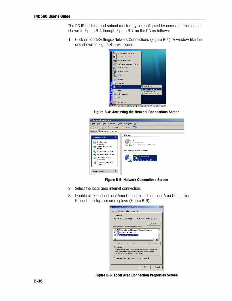
IND560 User’s Guide
The PC IP address and subnet mask may be configured by accessing the screens shown in Figure B-4 through Figure B-7 on the PC as follows:
1. Click on Start>Settings>Network Connections (Figure B-4). A window like the one shown in Figure B-5 will open.
Figure B-4: Accessing the Network Connections Screen
Figure B-5: Network Connections Screen
2. Select the local area internet connection.
3. Double click on the Local Area Connection. The Local Area Connection Properties setup screen displays (Figure B-6).
Figure B-6: Local Area Connection Properties Screen
B-36

IND560 User’s Guide
4. Scroll down to Internet Protocol (TCP/IP) and select it.
5. Click on the Properties button. The Internet Protocol (TCP/IP) Properties Screen displays (Figure B-7).
Figure B-7: Internet Protocol (TCP/IP) Properties Screen
6. Typically, “Obtain an IP address automatically” is checked. However, to connect to the IND560, set the PC IP address and subnet mask by selecting “Use the following IP address”.
7. Enter the IP address and subnet mask settings for the specific PC.
8. Click on the OK button.
After disconnecting from the IND560 and before connecting back to the PC’s normal network connection, remember to change the Internet Protocol (TCP/IP) Properties Screen setting back to “Obtain an IP address automatically” or to whatever setting was active when the screen was accessed.
Ethernet Demand Output If a demand output connection to Ethernet is made in the connections section of setup, a remote device may “register” to receive the data through the Ethernet port. In order to do this, the remote device must login to the shared data server and send the command to register for the data. The login can be any valid username and password for the terminal.
When a user logs into the shared data server, he or she acquires the level of access for the username and password used. All levels of users can receive a demand string.
If a demand output connection to EPrint is made in the Connections section of setup, a remote device is not required to “register” with the Shared Data Server to receive the data through the Ethernet port. The data string simply contains the assigned template’s information. The EPrint connection is made via the secondary TCP/IP port at the user-defined port number (set up at Communication > Network > Port).
B-37

IND560 User’s Guide
B-38
Registering for the Demand Output The “printout” command allows the client to define a Demand Print Stream as a callback field. The Demand Print Streams include demand print (triggered by the scale) and custom triggers (triggers 1, 2, and 3). The console print server sends a message to the client at each print output. Since print messages can span multiple message blocks (depending upon size), the start of the print message has a <dprint> tag and the end of the message has a </dprint > tag. After registering for the demand output, the client will receive the appropriate data stream. The “ctimer” command specifies the minimum time between repeated callback messages. The “xprintout” command removes the registration from the terminal and the communication will stop.
The “xgroup all” command will also terminate any demand output registrations.
Sequence Example 1 1. Enter the menu tree of setup.
2. In the Connections sub-block of the Communications block of setup, create a connection for Demand Output assignment to the Ethernet port triggered by Scale using Template 2.
3. Ensure that the IP and Gateway addresses are programmed properly.
4. Login to the shared data server from the client, (see “user” command in the Shared Data Server section).
5. Register to receive the demand data by entering the “printout 1” command.
6. The IND560 will acknowledge the registration with a message [00Gxxx~number PRINTOUT streams=1]. Now, whenever a demand print is generated, the Template 2 data will be sent to the client.
00P004 <dprint>Scale 1 01:33:10 06/Sep/2005 17.08 lb 17.08 lb T 0.00 lb N </dprint>
The “xprintout” command allows the client to remove the print output callback registration thus stopping the demand output.
Sequence Example 2 1. Enter the menu tree of setup.
2. In the Connections sub-block of the Communications block of setup, create a connection for Demand Output assignment to the Ethernet port triggered by Trigger 1 using Template 1.
3. Ensure that the IP and Gateway addresses are programmed properly.

IND560 User’s Guide
B-39
4. Login to the shared data server from the client, (see “user” command in the Shared Data Server section).
5. Register to receive the demand data by entering the “printout 1” command.
6. The IND560 will acknowledge the registration with a message [00Gxxx~number PRINTOUT streams=1]. Now, whenever the custom trigger is initiated (by a programmed discrete input or PLC command), the Template 1 data will be sent to the client.
00P004 <dprint> 17.08 lb 17.08 lb T 0.00 lb N </dprint>
The “xprintout” command allows the client to remove the print output callback registration thus stopping the demand output.
Ethernet Continuous Output If a continuous output type of connection to Eprint is made in the connections section of setup, a remote device is not required “register” with the Shared Data server, to receive data through the Ethernet port. The data string simply contains the assigned continuous output or template information. The Eprint connection is made via the secondary TCP/IP port a the user-defined secondary port number (configured in setup at Communication>Network>Port).
If a continuous output or continuous template output connection to Ethernet 1 is made in the connections section of setup, a remote device must “register” to receive the data through the Ethernet port. In order to do this, the remote device must login to the shared data server and send the command to “register” for the data. The login can be any valid username and password for the terminal.
When a user logs onto the shared data server, they acquire the level of access for the username and password used. All levels of users can receive a continuous string.
Registering for the Continuous Output The “contout” command allows the client to define the continuous output string as a callback field. The Console Print Server sends a message to the client at each continuous output. The continuous output message is either in the Standard METTLER TOLEDO Continuous Output format or in a continuous template format. The “ctimer” command specifies the minimum time between repeated callback messages. The “xcontout” command removes the registration from the terminal and the communication will stop.
The “xgroup all” command will also terminate any continuous output registrations.
Sequence Example 1. Enter the menu tree of setup.

IND560 User’s Guide
B-40
2. In the Connections sub-block of the Communications block of setup, create a connection for Continuous Output assignment to the Ethernet port triggered by Scale.
3. Ensure that the IP and Gateway addresses are programmed properly.
4. Login to the shared data server from the client, (see “user” command in the Shared Data Server section).
5. Register to receive the continuous data by entering the “contout” command.
6. The IND560 will acknowledge the registration with a message [00Gxxx~number CONTOUT streams=1]. Now, whenever a continuous output string is generated by the IND560, the data will be sent to the client.
00C148 14! 354 236 > 00C149 14! 354 236 > 00C150 14! 354 236 > 00C151 14! 354 236
The “xcontout” command allows the client to remove the continuous output callback registration thus stopping the continuous output.
The output rate of a Continuous type output over Ethernet is 20Hz by default. This rate cannot be modified through the terminal setup menu. However, the output rate can me modified by a Shared Data write to a field in the “cs” block of Shared Data. Please refer to the IND560 Shared Data Reference on the documentation CD for specifics.
FTP The IND560 provides the ability to transfer files using FTP (file transfer protocol). METTLER TOLEDO recommends the use of the InSIte PC program to assist in this transfer, but files can also be transferred through the Command prompt using an FTP client with the following commands.
fget (serial) or get (Ethernet) – all files can be read using this command
fput (serial) or put (Ethernet) – only certain files can be downloaded back to the IND560 terminal
In order to access any files from the IND560, the client must login to the FTP server. Valid usernames and passwords are entered in the setup under Communications, Network, FTP and each username is assigned an access level. All access levels can read files but only maintenance and administrator levels can write new files to the terminal (see Chapter 3.0, Configuration for further information about configuring FTP usernames, passwords, and access levels).
The following list indicates the path for the available files that can be accessed using the “fget” and “fput” commands.

IND560 User’s Guide
B-41
flash:\tare.bin Binary file that contains all the tare table records. This file is in a binary format and is not directly editable. The InSite program provides the ability to edit the records and download back to the terminal.
The Tare Table is also available as a .csv file. This file is stored in the flash2 directory as flash2:\A1.csv The format of this comma-separated value file is: ID, Tare, Description, Unit, n, Total. Units are listed as defined in Shared Data variable td0125. The A1.csv file can be created or modified externally and downloaded to the terminal.
flash:\target.bin Binary file that contains all the target table records. This file is in a binary format and is not directly editable. The InSite program provides the ability to edit the records and download back to the terminal.
The Target Table is also available as a .csv file. This file is stored in the flash2 directory as flash2:\A2.csv. The format of this comma separated value file is: ID, Description, Target, Unit, Spill, + Tolerance, -Tolerance, Fine Feed. Units are listed as defined in Shared Data variable td0125. The A2.csv file can be created or modified externally and downloaded to the terminal.
flash:\cont.bin Binary file that contains all the container tare table records from the IND560-Fill application software. This file is in a binary format and is not directly editable. The InSite program provides the ability to edit the records and download back to the terminal.
The Container Tare Table is also available as a .csv file. This file is stored in the flash2 directory as flash2:\cont.csv. The format of this comma separated value file is: ID, Unit, Tare, Minimum, Maximum, Description, n, Total. Units are listed as defined in Shared Data variable td0125. The cont.csv file can be created or modified externally and downloaded to the terminal.
ram:\caltest1.cfg A text file that defines the calibration test procedure.
ram:\caltw1.txt A text file that lists the test weight values and identification string for the test weights used in the calibration test.
ram:\saver.bmp A 35 x 35 pixel bitmap file used as a screen saver.
gen:\change.csv A comma-delimited file of the change log in the IND560 terminal. This file can only be read from the terminal – it cannot be written back to the terminal.
gen:\maint.csv A comma-delimited file of the maintenance log in the IND560 terminal. This file can only be read from the terminal – it cannot be written back to the terminal.

IND560 User’s Guide
B-42
gen:\bkram.dmt gen:\flash.dmt gen:\E2prom1.dmt
These three files are the backup files for all of the setup parameters in the terminal. Retrieving and storing these files enables reloading of the terminal with the current parameters in case of a catastrophic failure.
New Shared Data has been added to v3.02 firmware to add ftp access control. The assignment of share data field nf0101 now affects ftp access rights. Please refer to the Shared Data Reference manual on the documentation CD for full details.
FTP over Ethernet Example The following procedure describes how one might upload the calibration test to a PC running Microsoft Windows, modify the file, and then download it again to the terminal. The complete sequence is shown in Figure B-8.
1. A valid username and password from the FTP server of the IND560 terminal is required. Refer to Chapter 3.0, Configuration, Communication, Network, FTP.
2. The client must also know the IP address of the IND560 and a valid network connection established between the client and the terminal is required before beginning. Refer to the Ethernet section, Ethernet Connection to a PC earlier in this Appendix.
3. Open the command prompt window in the client PC and type: ftp
4. Press ENTER. The command line should now display: ftp>.
5. To open the FTP connection, type open xxx.xxx.xxx.xxx where the xxx.xxx.xxx.xxx represents the IP address of the IND560 terminal.
6. Press ENTER. The display should indicate that service is ready and prompt for the username.
7. Enter the username from the IND560 FTP user list.
8. Press ENTER. If the username is valid, the display will prompt for a password.
9. Enter the password for the username used.
10. Press ENTER. If the login procedure was successful, the prompt line will now display: ftp>
11. Enter the command: get ram:\caltest1.cfg
12. Press ENTER. This command will upload the calibration test procedure to the directory that was showing in the command prompt line before the FTP program was started. The client screen should indicate that the transfer was successful.
13. Modify the file as required.
14. Download the modified file to the IND560 by typing:
put caltest1.cfg ram:\caltest.cfg
The client screen should indicate that the transfer was successful.
15. After the transfer is complete, type: quit

IND560 User’s Guide
16. Press ENTER to exit the FTP process. An acknowledgment message: Bye displays.
17. Type: exit
18. Press ENTER to close the command line screen and return to Windows.
Figure B-8: Example FTP Sequence
Terminal Updates Uploading New Firmware A new version of firmware can be loaded into the IND560 using either the Ethernet or COM1 serial port and the METTLER TOLEDO software program InSite. Firmware can also be upgraded using the USB port and an external USB flash memory device. These procedures are defined in Chapter 4.0, Service and Maintenance, Upgrading Firmware.
Uploading Customized Softkey Graphics Customized graphics for home screen softkeys may be uploaded to the IND560 terminal either using ftp through an Ethernet connection, or through a serial connection. The file names of each graphic must match the filename of the graphic it is to be replaced. Lists of these filenames are provided in Chapter 2, Operation.
FTP Upload Open a DOS window and navigate to the folder where the new Softkey bitmaps are available.
Once the command line is showing the path of the new bitmaps, open an ftp connection with the IND560, as shown in Figure B-8
B-43

IND560 User’s Guide
At the ftp prompt, type “put filename.bmp flash:\filename.bmp”. The filename of the new graphic must be the same as that of the bitmap it replaces. This process can be repeated to upload multiple bitmap files.
Once all the new softkey graphics are uploaded, quit the ftp session and close the DOS window. The new softkey graphic can now be used in the terminal, when selected in setup at Terminal > Softkeys.
Serial Upload To upload graphics through a serial connection:
1. Use HyperTerminal (or equivalent) to make a serial connection (with Baud = 115200, Data Bits = 8, Parity Bit = None, Stop Bits = 1, Flow Control = 0) to the IND560 from the PC where the customized graphics reside.
2. Log in to the Shared Data server as admin. Enter a password if the terminal is configured to require one. To upload files, the login must be at the administrator level.
3. After receiving the “Access OK” prompt, type “fput flash:\filename.bmp”, where filename.bmp is the name of the graphic to be uploaded.
4. The IND560 will begin to send C characters (visible in Figure B-9) to indicate that it is in serial communication with the PC.
5. Access the Transfer | Send File menu. In the dialog box that appears (Figure B-9), browse to the graphic file to be uploaded, and select it. In the Protocol selection box, choose 1K Xmodem.
Figure B-9: Send File Dialog Box
6. Click OK. A progress bar will indicate that the file is being uploaded. Once upload is complete, the Cancel button changes to OK (Figure B-10). Close the dialog box.
B-44

IND560 User’s Guide
Figure B-10: File Transfer Dialog Box
7. When the “OK” prompt displays in HyperTerminal, if required repeat steps 3 to 6 to upload another customized graphic file.
8. Once all files have been uploaded, at the command prompt type “write qc0149 1”. This command causes the IND560 to save the changes made during the upload session.
9. Finally, close the connection and quit HyperTerminal.
B-45

METTLER TOLEDO 1900 Polaris Parkway Columbus, Ohio 43240
METTLER TOLEDO® is a registered trademark of Mettler-Toledo, Inc. ©2010 Mettler-Toledo, Inc.
71209396