Incubator Analyzer...incubator analyzer that verifies the operation and environment of baby...
76
PN FBC-0091 October 2015, Rev. 2, 1/16 © 2015-2016 Fluke Corporation. All rights reserved. Specifications are subject to change without notice. All product names are trademarks of their respective companies. INCU ™ II Incubator Analyzer Users Manual
Transcript of Incubator Analyzer...incubator analyzer that verifies the operation and environment of baby...

PN FBC-0091 October 2015, Rev. 2, 1/16 © 2015-2016 Fluke Corporation. All rights reserved. Specifications are subject to change without notice. All product names are trademarks of their respective companies.
INCU™ II Incubator Analyzer
Users Manual
Warranty and Product Support
Fluke Biomedical warrants this instrument against defects in materials and workmanship for one year from the date of original purchase OR two years if at the end of your first year you send the instrument to a Fluke Biomedical service center for calibration. You will be charged our customary fee for such calibration. During the warranty period, we will repair or at our option replace, at no charge, a product that proves to be defective, provided you return the product, shipping prepaid, to Fluke Biomedical. This warranty covers the original purchaser only and is not transferable. The warranty does not apply if the product has been damaged by accident or misuse or has been serviced or modified by anyone other than an authorized Fluke Biomedical service facility. NO OTHER WARRANTIES, SUCH AS FITNESS FOR A PARTICULAR PURPOSE, ARE EXPRESSED OR IMPLIED. FLUKE SHALL NOT BE LIABLE FOR ANY SPECIAL, INDIRECT, INCIDENTAL OR CONSEQUENTIAL DAMAGES OR LOSSES, INCLUDING LOSS OF DATA, ARISING FROM ANY CAUSE OR THEORY.
This warranty covers only serialized products and their accessory items that bear a distinct serial number tag. Recalibration of instruments is not covered under the warranty.
This warranty gives you specific legal rights and you may also have other rights that vary in different jurisdictions. Since some jurisdictions do not allow the exclusion or limitation of an implied warranty or of incidental or consequential damages, this limitation of liability may not apply to you. If any provision of this warranty is held invalid or unenforceable by a court or other decision-maker of competent jurisdiction, such holding will not affect the validity or enforceability of any other provision.
7/07

Notices
All Rights Reserved Copyright 2016, Fluke Biomedical. No part of this publication may be reproduced, transmitted, transcribed, stored in a retrieval system, or translated into any language without the written permission of Fluke Biomedical.
Copyright Release Fluke Biomedical agrees to a limited copyright release that allows you to reproduce manuals and other printed materials for use in service training programs and other technical publications. If you would like other reproductions or distributions, submit a written request to Fluke Biomedical.
Unpacking and Inspection Follow standard receiving practices upon receipt of the instrument. Check the shipping carton for damage. If damage is found, stop unpacking the instrument. Notify the carrier and ask for an agent to be present while the instrument is unpacked. There are no special unpacking instructions, but be careful not to damage the instrument when unpacking it. Inspect the instrument for physical damage such as bent or broken parts, dents, or scratches.
Technical Support For application support or answers to technical questions, either email [email protected] or call 1-800- 850-4608 or 1-440-248-9300. In Europe, email [email protected] or call +31-40-2965314.
Claims Our routine method of shipment is via common carrier, FOB origin. Upon delivery, if physical damage is found, retain all packing materials in their original condition and contact the carrier immediately to file a claim. If the instrument is delivered in good physical condition but does not operate within specifications, or if there are any other problems not caused by shipping damage, please contact Fluke Biomedical or your local sales representative.

Returns and Repairs Return Procedure
All items being returned (including all warranty-claim shipments) must be sent freight-prepaid to our factory location. When you return an instrument to Fluke Biomedical, we recommend using United Parcel Service, Federal Express, or Air Parcel Post. We also recommend that you insure your shipment for its actual replacement cost. Fluke Biomedical will not be responsible for lost shipments or instruments that are received in damaged condition due to improper packaging or handling.
Use the original carton and packaging material for shipment. If they are not available, we recommend the following guide for repackaging:
Use a double–walled carton of sufficient strength for the weight being shipped. Use heavy paper or cardboard to protect all instrument surfaces. Use nonabrasive material around all projecting parts. Use at least four inches of tightly packed, industry-approved, shock-absorbent material around the instrument.
Returns for partial refund/credit:
Every product returned for refund/credit must be accompanied by a Return Material Authorization (RMA) number, obtained from our Order Entry Group at 1-440-498-2560.
Repair and calibration:
To find the nearest service center, go to www.flukebiomedical.com/service or
In the U.S.A and Asia.: Cleveland Calibration Lab Tel: 1-800-850-4608 x2564 Email: [email protected]
In Europe, Middle East, and Africa: Eindhoven Calibration Lab Tel: +31-40-2675300 Email: [email protected]
To ensure the accuracy of the Product is maintained at a high level, Fluke Biomedical recommends the product be calibrated at least once every 12 months. Calibration must be done by qualified personnel. Contact your local Fluke Biomedical representative for calibration.

Certification This instrument was thoroughly tested and inspected. It was found to meet Fluke Biomedical’s manufacturing specifications when it was shipped from the factory. Calibration measurements are traceable to the International System of Units (SI) through recognized national measurement institutes, ratiometric techniques, or natural physical constants.
WARNING Unauthorized user modifications or application beyond the published specifications may result in electrical shock hazards or improper operation. Fluke Biomedical will not be responsible for any injuries sustained due to unauthorized equipment modifications.
Restrictions and Liabilities Information in this document is subject to change and does not represent a commitment by Fluke Biomedical. Changes made to the information in this document will be incorporated in new editions of the publication. No responsibility is assumed by Fluke Biomedical for the use or reliability of software or equipment that is not supplied by Fluke Biomedical, or by its affiliated dealers.
Manufacturing Location The INCU II is manufactured for Fluke Biomedical, 6920 Seaway Blvd., Everett, WA, U.S.A.


i
Table of Contents
Title Page
Introduction .................................................................................................................... 1 Intended Use .................................................................................................................. 1 Safety Information .......................................................................................................... 2 Symbols ......................................................................................................................... 3 Glossary ......................................................................................................................... 4 Unpack the Analyzer ...................................................................................................... 6
Analyzer Familiarization ............................................................................................ 8 Analyzer Controls ...................................................................................................... 10
Setup the Analyzer ......................................................................................................... 12 Turn on the Analyzer ................................................................................................. 12 Select a Menu Item .................................................................................................... 12 Set the Language on the Analyzer ............................................................................ 12 Use the Analyzer Keyboard ....................................................................................... 12 Setup Menu ............................................................................................................... 13 Setup Communications ............................................................................................. 14

INCU™ II Users Manual
ii
Analyzer Operation ........................................................................................................ 16 Placement Pad .......................................................................................................... 16 Pretest Check ........................................................................................................... 19 Clear Memory ........................................................................................................... 19 Test Preparation ....................................................................................................... 19 STC ........................................................................................................................... 20 Probe Connections ................................................................................................... 22 Save a Test ............................................................................................................... 25 View Saved Tests ..................................................................................................... 25 Delete Tests .............................................................................................................. 26 Save Tests to a PC ................................................................................................... 26 Excel Add-in .............................................................................................................. 26
Menus ............................................................................................................................ 27 General Test ............................................................................................................. 27 Individual Test ........................................................................................................... 28 Test Groups .............................................................................................................. 28
Create Test Groups .............................................................................................. 28 View and Start a Test Group ................................................................................ 29
Test List by Standard ..................................................................................................... 30 Test List by Test Order .................................................................................................. 34 Test Procedures ............................................................................................................ 37
Warm-up Time .......................................................................................................... 37 Inside — Sound Level ............................................................................................... 38 Inside — Alarm Level ................................................................................................ 39 Outside — Alarm Level ............................................................................................. 40 Air Flow Velocity Threshold ...................................................................................... 41 Infant Contact Surface Temperature ......................................................................... 42 Skin Temperature Sensor Accuracy ......................................................................... 43 Temperature Distribution Accuracy ........................................................................... 43

Contents (continued)
iii
Operating Temperature Accuracy .............................................................................. 45 Uniformity of Temperature ......................................................................................... 46 Stability of Incubator Temperature ............................................................................. 47 Accuracy of Indicator ................................................................................................. 49 RH Accuracy ............................................................................................................. 50 Overshoot for Incubator Temperature ....................................................................... 51 Temperature Control Accuracy .................................................................................. 52 Overshoot of Temperature for Open Door ................................................................. 53 Operating on Battery Power ...................................................................................... 54 Change in Ambient Temperature............................................................................... 55
Maintenance and Troubleshooting ................................................................................. 56 Clean the Analyzer .................................................................................................... 57 Set the Calibration Factors ........................................................................................ 57 Troubleshooting ......................................................................................................... 58 Radio Frequency Certification ................................................................................... 58 Replaceable Parts and Accessories .......................................................................... 59
Specifications ................................................................................................................. 61 Environmental Specifications .................................................................................... 61 Measurements and Test Specifications ..................................................................... 62

INCU™ II Users Manual
iv
v
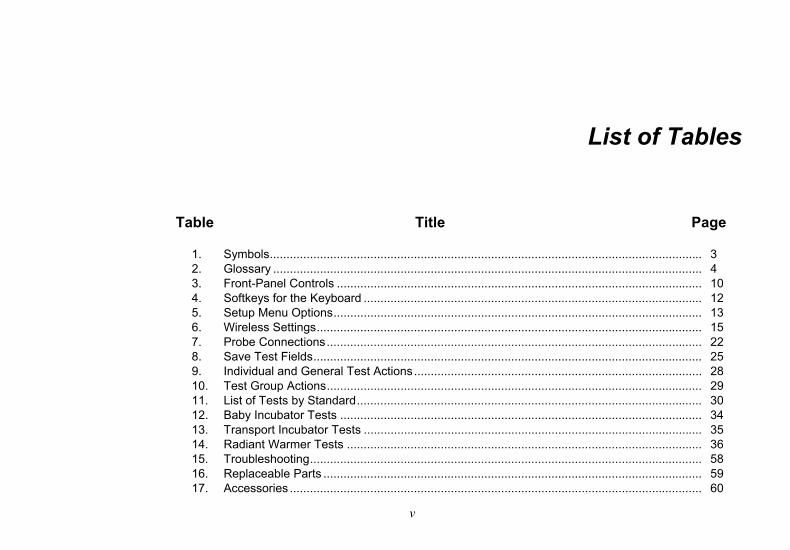
List of Tables
Table Title Page
1. Symbols ................................................................................................................................. 3 2. Glossary ................................................................................................................................ 4 3. Front-Panel Controls ............................................................................................................. 10 4. Softkeys for the Keyboard ..................................................................................................... 12 5. Setup Menu Options .............................................................................................................. 13 6. Wireless Settings ................................................................................................................... 15 7. Probe Connections ................................................................................................................ 22 8. Save Test Fields .................................................................................................................... 25 9. Individual and General Test Actions ...................................................................................... 28 10. Test Group Actions ................................................................................................................ 29 11. List of Tests by Standard ....................................................................................................... 30 12. Baby Incubator Tests ............................................................................................................ 34 13. Transport Incubator Tests ..................................................................................................... 35 14. Radiant Warmer Tests .......................................................................................................... 36 15. Troubleshooting ..................................................................................................................... 58 16. Replaceable Parts ................................................................................................................. 59 17. Accessories ........................................................................................................................... 60

INCU™ II Users Manual
vi

vii
List of Figures
Figure Title Page
1. Items included with the Analyzer ........................................................................................... 7 2. Connections .......................................................................................................................... 9 3. Front-Panel Controls ............................................................................................................. 11 4. Analyzer Placement .............................................................................................................. 16 5. Center the Probes on each Mattress Quadrant ..................................................................... 17 6. Analyzer and Puck Placement ............................................................................................... 18 7. Temperature Probe connections ........................................................................................... 21 8. Test Setup with Probes ......................................................................................................... 24

INCU™ II Users Manual
viii

1
Introduction The INCU™ II (the Analyzer or the Product) is a portable incubator analyzer that verifies the operation and environment of baby incubators, transport incubators, and radiant warmers. The Analyzer verifies the parameters that are important to the care of infants over time. These parameters include: temperature, airflow, sound, and humidity. The Analyzer has a rechargeable battery and can stay in the incubator chamber up to 24 hours without compromise to the integrity of the environment.
Intended Use The intended use for the analyzer is to test in compliance with standards, perform preventative maintenance, repair verification, and routine verification of baby incubators and radiant warmers.
The intended user is a trained biomedical equipment technician who performs periodic preventative maintenance checks on baby incubators and radiant warmers in service. Users can be associated with hospitals, clinics, original equipment manufacturers and independent service companies that repair and service medical equipment. The end user is an individual, trained in medical instrumentation technology. This Product is intended to be used in the laboratory environment, outside of the patient care area, and is not intended for use on patients, or to test devices while connected to patients. This Product is not intended to be used to calibrate medical equipment. It is intended for over the counter use. Designed around AAMI and IEC standards that specify incubator and radiant warmer sound levels, airflow, and thermal characteristics, the INCU II simultaneously measures airflow, relative humidity, sound, and five independent temperatures.

INCU™ II Users Manual
2
Safety Information A Warning identifies conditions and procedures that are dangerous to the user. A Caution identifies conditions and procedures that can cause damage to the Product or the equipment under test.
XW Warning
To prevent possible electrical shock, fire, or personal injury:
• Read all safety information before you use the Product.
• Carefully read all instructions.
• Use the Product only as specified, or the protection supplied by the Product can be compromised.
• Do not touch voltages >30 V ac rms, 42 V ac peak, or 60 V dc.
• Do not use the Product around explosive gas, vapor, or in damp or wet environments.
• Do not use the Product if it operates incorrectly.
• Use this Product indoors only.
• Use only the mains power cord and connector approved for the voltage and plug configuration in your country and rated for the Product.
• Replace the mains power cord if the insulation is damaged or if the insulation shows signs of wear.
• Use only the external mains power supply included with the Product.
• Use only current probes, test leads, and adapters supplied with the Product.
• Use only products accessories listed as standard or optional in this manual. Use only accessories approved by Fluke Biomedical.
• Disable the Product if it is damaged.
• Do not use the Product if it is damaged.
• Do not use a two-conductor mains power cord unless you install a protective ground wire to the Product ground terminal before you operate the Product.
• Do not put metal objects into connectors.
• Do not use an extension cord or adapter plug.
Incubator Analyzer Symbols
3
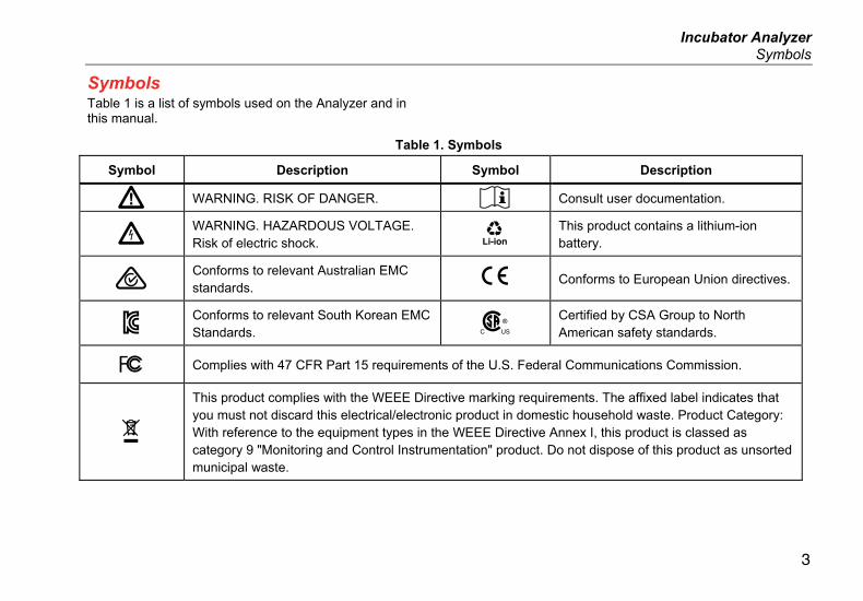
Symbols Table 1 is a list of symbols used on the Analyzer and in this manual.
Table 1. Symbols
Symbol Description Symbol Description
W WARNING. RISK OF DANGER. Consult user documentation.
X WARNING. HAZARDOUS VOLTAGE. Risk of electric shock.
This product contains a lithium-ion battery.
Conforms to relevant Australian EMC standards.
P Conforms to European Union directives.
à Conforms to relevant South Korean EMC Standards.
) Certified by CSA Group to North American safety standards.
� Complies with 47 CFR Part 15 requirements of the U.S. Federal Communications Commission.
~
This product complies with the WEEE Directive marking requirements. The affixed label indicates that you must not discard this electrical/electronic product in domestic household waste. Product Category: With reference to the equipment types in the WEEE Directive Annex I, this product is classed as category 9 "Monitoring and Control Instrumentation" product. Do not dispose of this product as unsorted municipal waste.
INCU™ II Users Manual
4
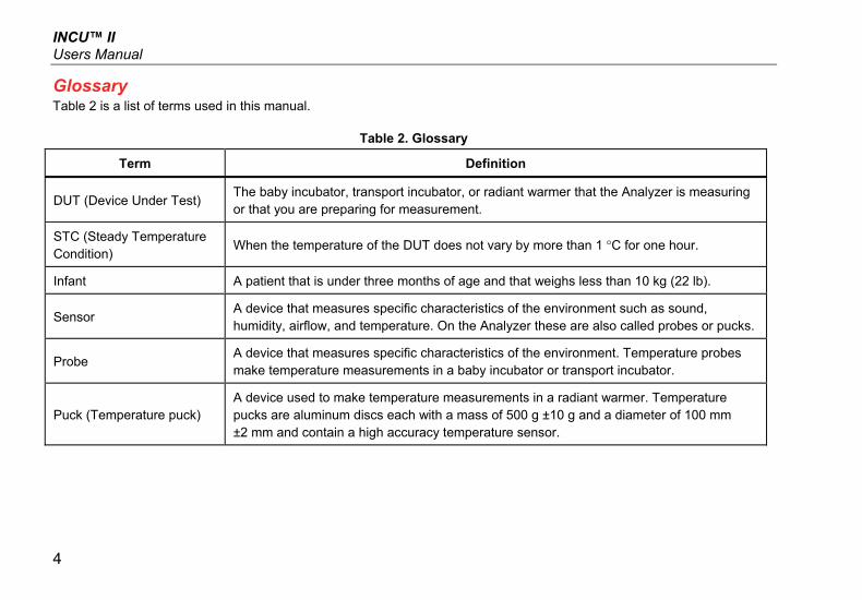
Glossary Table 2 is a list of terms used in this manual.
Table 2. Glossary
Term Definition
DUT (Device Under Test) The baby incubator, transport incubator, or radiant warmer that the Analyzer is measuring or that you are preparing for measurement.
STC (Steady Temperature Condition)
When the temperature of the DUT does not vary by more than 1 °C for one hour.
Infant A patient that is under three months of age and that weighs less than 10 kg (22 lb).
Sensor A device that measures specific characteristics of the environment such as sound, humidity, airflow, and temperature. On the Analyzer these are also called probes or pucks.
Probe A device that measures specific characteristics of the environment. Temperature probes make temperature measurements in a baby incubator or transport incubator.
Puck (Temperature puck) A device used to make temperature measurements in a radiant warmer. Temperature pucks are aluminum discs each with a mass of 500 g ±10 g and a diameter of 100 mm ±2 mm and contain a high accuracy temperature sensor.

Incubator Analyzer Glossary
5
Table 2. Glossary (cont.)
Term Definition
Normal condition
The DUT has all protections against hazards in place and the protections are operating.
Unless otherwise specified, all tests in this manual assume the DUT is operating in normal condition.
Air-controlled The DUT automatically keeps the air temperature constant by using an air temperature probe to make temperature measurements. Use the control on the DUT to set the temperature.
Baby-controlled The DUT automatically keeps the temperature constant by using a skin temperature probe to make temperature measurements. Use the control on the DUT to set the temperature.
Average temperature The average of the temperature measurements that are taken at regular intervals during STC.
Incubator temperature The temperature of the air 10 cm above the center of the mattress in the compartment of the DUT.

INCU™ II Users Manual
6
Unpack the Analyzer Carefully unpack all items from the box and check that you have the following items (See Figure 1):
INCU II
Air Flow Probe
Humidity Probe
Sound Probe
Temperature Probes (5 connector types: red, yellow, white, blue, and green)
Temperature Pucks (5 connector types: red, yellow, white, blue, and green)
Placement Pad
4 Tripods
USB Cable (Type A to Micro B)
K-Type Thermocouple
Power Adapter
Carrying Case
Included, but not pictured:
• Getting Started Manual
• Users Manual CD
• Skin Temperature Heater Assembly (optional)
• Carrying Case (pucks)

Incubator Analyzer Unpack the Analyzer
7
1 82
3
4
5
1211
7
6
9
10
hxy008.eps
Figure 1. Items included with the Analyzer
INCU™ II Users Manual
8
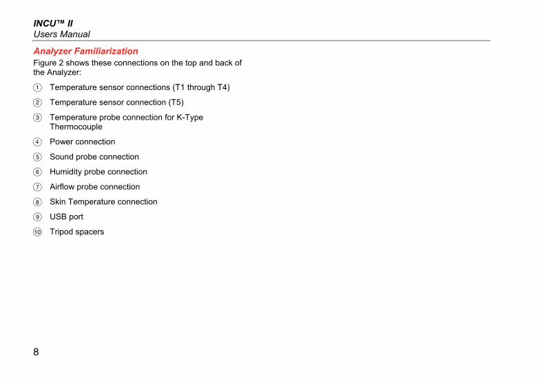
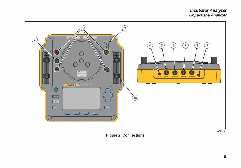
Analyzer Familiarization Figure 2 shows these connections on the top and back of the Analyzer:
Temperature sensor connections (T1 through T4)
Temperature sensor connection (T5)
Temperature probe connection for K-Type Thermocouple
Power connection
Sound probe connection
Humidity probe connection
Airflow probe connection
Skin Temperature connection
USB port
Tripod spacers
Incubator Analyzer Unpack the Analyzer
9
2
31
4 5 6 7 8 9
10
hxy001.eps
Figure 2. Connections
INCU™ II Users Manual
10
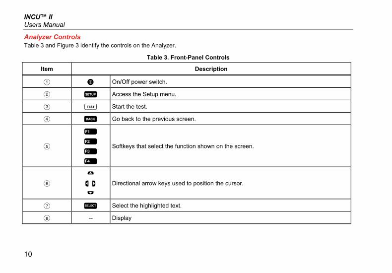
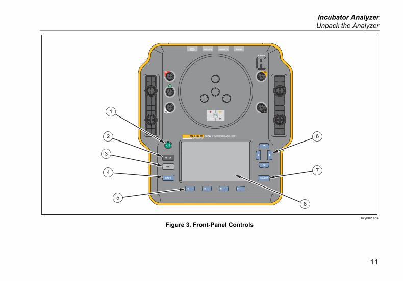
Analyzer Controls Table 3 and Figure 3 identify the controls on the Analyzer.
Table 3. Front-Panel Controls
Item Description
On/Off power switch.
Access the Setup menu.
Start the test.
Go back to the previous screen.
Softkeys that select the function shown on the screen.
Directional arrow keys used to position the cursor.
Select the highlighted text.
-- Display
Incubator Analyzer Unpack the Analyzer
11
1
2
3
6
7
8
4
5
hxy002.eps
Figure 3. Front-Panel Controls
INCU™ II Users Manual
12
Setup the Analyzer Turn on the Analyzer Before you turn on the Analyzer, check all cables and connections for damage or wear. Replace any damaged components before use.
Secondary cells and batteries need to be charged before use. Always use the correct charger and refer to the manufacturer’s instructions or equipment manual for proper charging instructions.
To turn on the Analyzer, push .
The Analyzer does a self-check. When the Analyzer is ready for operation, the Main menu shows on the display.
Select a Menu Item To make a selection:
1. Use and to highlight the menu item.
2. Push .
Set the Language on the Analyzer To set the language:
1. Push .
2. Use and to highlight Language and then push .
3. Highlight the language to use and then push .
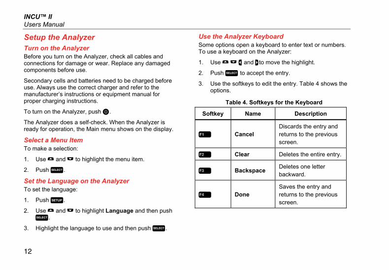
Use the Analyzer Keyboard Some options open a keyboard to enter text or numbers. To use a keyboard on the Analyzer:
1. Use and to move the highlight.
2. Push to accept the entry.
3. Use the softkeys to edit the entry. Table 4 shows the options.
Table 4. Softkeys for the Keyboard
Softkey Name Description
Cancel Discards the entry and returns to the previous screen.
Clear Deletes the entire entry.
Backspace Deletes one letter backward.
Done Saves the entry and returns to the previous screen.
Incubator Analyzer Setup the Analyzer
13
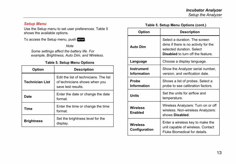
Setup Menu Use the Setup menu to set user preferences. Table 5 shows the available options.
To access the Setup menu, push .
Note
Some settings affect the battery life. For example, Brightness, Auto Dim, and Wireless.
Table 5. Setup Menu Options
Option Description
Technician List Edit the list of technicians. The list of technicians shows when you save test results.
Date Enter the date or change the date format.
Time Enter the time or change the time format.
Brightness Set the brightness level for the display.
Table 5. Setup Menu Options (cont.)
Option Description
Auto Dim
Select a duration. The screen dims if there is no activity for the selected duration. Select Disabled to turn off the feature.
Language Choose a display language.
Instrument Information
Show the Analyzer serial number, version, and verification date.
Probe Information
Shows a list of probes. Select a probe to see calibration factors.
Units Set the units for airflow and temperature.
Wireless Enabled
Wireless Analyzers: Turn on or off wireless. Non-wireless Analyzers: shows Disabled.
Wireless Configuration
Enter a wireless key to make the unit capable of wireless. Contact Fluke Biomedical for details.

INCU™ II Users Manual
14
Table 5. Setup Menu Options (cont.)
Option Description
Temperature Sampling Rate
For single and group tests: select how often the Analyzer will measure and record the temperature. (For General tests, see General Test.)
Heater Assembly
Select whether or not the optional Skin Temperature Heater Assembly is available.
Setup Communications The Analyzer has a USB Device Port for communication to a computer (PC). Some Analyzers also have wireless functionality. Use the communications ports to:
• Send saved test records to a PC.
Operating system requirements:
• Windows Vista
• Windows 7
• Windows 8 or later
For Analyzers with wireless functionality, the wireless port communicates with a PC that has an 802.15.1 wireless interface. For PCs without the interface, use a commercially available USB adapter. The PC starts the interface when you connect the adapter. (Additional software is not necessary.)
The PC sees the wireless port while the Analyzer is on. When the Analyzer is turned off, the PC closes the port. When the wireless device is assigned to a COM port, the COM port reopens when the Analyzer is turned on.
Note
The wireless port on the Analyzer is a Classic 802.15.1 port not a Low Energy 802.15.1 port.
To install a wireless device:
1. Right-click the Bluetooth Devices icon and select Add a Device, or select Show Bluetooth Devices | Add a Device.
The Analyzer shows in the window. The serial number of the Analyzer is part of the name.
Note
It is okay if the icon shows as a headset, or with the name, Bluetooth headset. These are defaults.The name will change to the Analyzer.
2. Select the Analyzer and click Next.
The system prompts you to compare the codes. Ignore the message and continue with the next step.

Incubator Analyzer Setup the Analyzer
15
3. Make sure Yes is selected and click Next.
4. Select Driver Software Installation.
The system installs two COM ports. Ignore the message that the peripheral device failed, and close the window. The Add a Device window shows the device successfully added to the computer.
5. Close the Add a Device window.
6. Right-click the wireless icon and select Show Bluetooth Devices.
The Analyzer name (including serial number) shows. Ignore the message about the missing driver for the peripheral device.
7. Right-click the Analyzer and select Properties.
The Hardware section shows a COM port.
The Bluetooth Settings COM ports section shows two COM ports. The system uses the Outgoing port only.
Wireless Settings—For Analyzers with wireless functionality, Table 6 shows the settings. You do not need to change the default settings. Choose a method to open the settings:
• Right-click the wireless icon and select Open Settings.
• Right-click Bluetooth from the Start menu.
• If you installed an adapter, select Control Panel | Devices and Printers, then right-click the adapter and select Bluetooth Settings.
Table 6. Wireless Settings
Option Recommended
Setting
Allow Bluetooth devices to connect to this computer.
Selected (Required)
Alert me when a new Bluetooth device wants to connect.
Selected
Show the Bluetooth icon in the notification area.
Selected
Allow Bluetooth devices to find this computer.
Not selected (The PC uses the Outgoing COM port to find the Analyzer.)
INCU™ II Users Manual
16
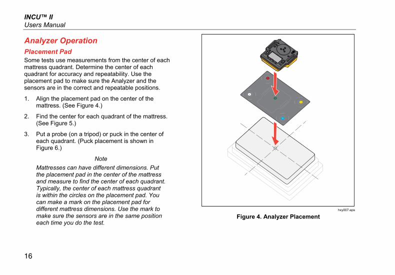
Analyzer Operation Placement Pad Some tests use measurements from the center of each mattress quadrant. Determine the center of each quadrant for accuracy and repeatability. Use the placement pad to make sure the Analyzer and the sensors are in the correct and repeatable positions.
1. Align the placement pad on the center of the mattress. (See Figure 4.)
2. Find the center for each quadrant of the mattress. (See Figure 5.)
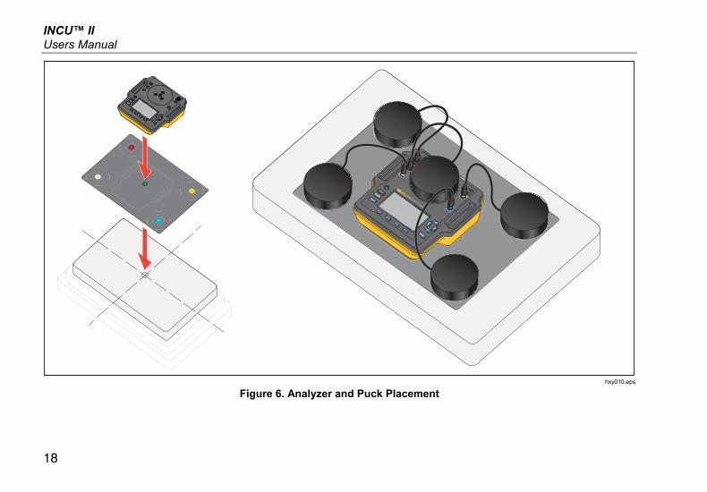
3. Put a probe (on a tripod) or puck in the center of each quadrant. (Puck placement is shown in Figure 6.)
Note
Mattresses can have different dimensions. Put the placement pad in the center of the mattress and measure to find the center of each quadrant. Typically, the center of each mattress quadrant is within the circles on the placement pad. You can make a mark on the placement pad for different mattress dimensions. Use the mark to make sure the sensors are in the same position each time you do the test.
hxy007.eps
Figure 4. Analyzer Placement

Incubator Analyzer Analyzer Operation
17
AB
C
AB
C
A
A
A
hxy012.eps
Figure 5. Center the Probes on each Mattress Quadrant
INCU™ II Users Manual
18
hxy010.eps
Figure 6. Analyzer and Puck Placement
Incubator Analyzer Analyzer Operation
19
Pretest Check Before beginning a test, check the battery life and the available memory:
1. Push .
2. Use and to highlight Instrument Information and then push .
The display shows the percentage of available battery life and the percentage of available memory.
Clear Memory When the memory is 80 % full the Analyzer indicates the percentage of memory in use. To clear the memory:
1. Push .
2. Use and to highlight Instrument Information and then push .
3. To clear the memory, push (Clear Memory) and then push .
Test Preparation The Analyzer can test baby incubators, transport incubators, and radiant warmers. Each DUT has a standard that governs the device compliance. See Table 11 for a list of standards.
Before you begin any test:
• Make sure you can support the requirements for each test. Some tests require a change in ambient temperatures or a probe in a specific location.
• Make sure there is enough memory to store the complete set of measurements for the test. Higher sampling rates will require more memory.
• Make sure the battery is fully charged before beginning tests that use battery life. See Pretest Check. Tests that require additional time after STC or that have a higher sampling rate use more battery. To prevent potential data loss, Fluke Biomedical recommends that you plug the Analyzer into power for longer tests.
• Unless directed, set the DUT for normal operation.

INCU™ II Users Manual
20
• Connect the probes or pucks before you start the test. The Analyzer shows the results only from the sensors that are connected before the start of the test. For an example of test setup see Figure 8.
• Make sure that the Analyzer uses the correct calibration factors for temperature tests. Always use probes for an incubator or transport incubator. Always use pucks for a radiant warmer.
• Each sensor has a unique set of calibration factors. If you replace a probe or puck, you must enter the new calibration factors before you use the sensor. The Analyzer requires the correct calibration factors for measurement accuracy.
• To make sure the Analyzer uses the correct calibration factors, always connect the temperature probes or pucks to the correct color-coded jack. See Figure 7.
• For tests that have the Test Time option Run Continuously (runs until stopped), the test must run for the minimum test time to get a valid result.
• Some tests require specific actions after the DUT gets to STC. To make sure the test results are valid for the standard, you must complete all the steps in the procedure within the Test Time.
• To maximize the accuracy of the data, Pass/Fail calculations are based on a sample rate of 1 sample per second. If you change the sample rate, it impacts the exported data. Exported data with the modified sample rate shows the general shape of the data.
STC STC is a steady temperature condition for at least one hour. When the Analyzer calculates that the DUT has reached STC, the Analyzer records the time on the results screen.

Incubator Analyzer Analyzer Operation
21
hxy009.eps
Figure 7. Temperature Probe connections
INCU™ II Users Manual
22
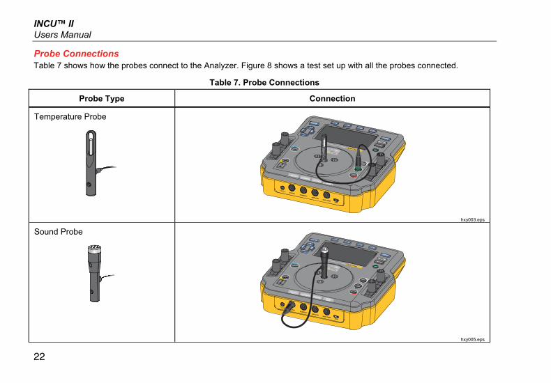
Probe Connections Table 7 shows how the probes connect to the Analyzer. Figure 8 shows a test set up with all the probes connected.
Table 7. Probe Connections
Probe Type Connection
Temperature Probe
hxy003.eps
Sound Probe
hxy005.eps

Incubator Analyzer Analyzer Operation
23
Table 7. Probe Connections (cont.)
Probe Type Connection
Humidity Probe
hxy004.eps
Air Flow Probe
hxy006.eps

INCU™ II Users Manual
24
hxy011
Figure 8. Test Setup with Probes

Incubator Analyzer Analyzer Operation
25
Save a Test You can save the results from an individual test or save all the results for a test group. The Analyzer prompts you for information. See Table 8.
To save an individual or general test, push (Save).
To save and exit a test group, wait until the group is complete or push (Stop) to stop the test. On the Overview screen, push (Save). The Analyzer stops the test group and saves the results.
View Saved Tests To view saved tests from the Main menu:
1. Push (View Saved Data).
• Individual test – use and to highlight a test and push to see the Results screen.
• Test Group – use and to highlight the group and push to see the Overview screen. Highlight the test and push to see the Results screen.
2. From the Results screen you can:
• Toggle between Details and Results, push .
• Return to the test group Overview screen, push (Pass/Fail).
• Delete a test, push (Delete) then highlight OK and push .
Table 8. Save Test Fields
Field Description
Test Environment
The type of device where the test was done. For a test group, you can select the type of DUT.
Technician The name of the technician that did the test. Select from the list or add a new technician name.
Incubator ID The identification for the DUT. Use the alphanumeric keyboard on the Analyzer to enter the ID.
Location The location of the DUT. Use the alphanumeric keyboard on the Analyzer to enter the location.

INCU™ II Users Manual
26
Delete Tests You can delete tests from the Main menu. Push (View Saved Data). From the Saved Data screen you can:
• Delete all the tests: push (Delete All) then highlight OK and push .
• Delete an individual test:
a. Use and to highlight the test or test group.
b. Push (Delete) then highlight OK and push .
Save Tests to a PC You can use a PC to transfer and view completed data from the Analyzer. Install the Ansur mini plug-in and the custom Excel add-in spreadsheet. Both are available on the CD or from www.flukebiomedical.com.
1. Use the provided USB cable to connect the Analyzer to the PC.
2. Make sure the main menu shows on the Analyzer.
3. On the PC, open the plug-in to transfer the files.
Excel Add-in Use the Excel Add-in on a PC to view results data. The Excel Add-in has these worksheets:
• Configuration – opens files from the PC and sets the default views.
• View_Result – shows a summary of the data in Results Mode (tabular test data) or View Mode (graphical format).
• Data – shows the raw data

Incubator Analyzer Menus
27
Menus From the Main menu, you can select a test environment, take a general test, or view saved tests.
General Test Use the General Test to take readings from any sensor that is connected to the Analyzer. To do a General test:
1. Push (General Test).
2. Use and to highlight the type of temperature sensor you have connected and push .
WCaution
Make sure to select the correct type of sensor. The wrong type of sensor will give inaccurate readings.
3. To select the sampling rate:
a. Push (Sample Rate).
b. Highlight the sample rate to change and push .
c. Highlight the new sample rate and push .
d. When you have set the sample rates, push (Done).
4. Push .
The Analyzer takes measurements from each of the attached sensors and shows the results on the display.
Note
Airflow measurements require time for the environment to stabilize. For more accurate air flow measurements, allow readings to stabilize for ten minutes.
Note
To maximize the accuracy of airflow measurements, do not use other probes when you make an airflow measurement. If other probes are attached, position the probes to prevent interference with the airflow path to the airflow probe. Place the airflow probe perpendicular to the direction of airflow inside the incubator.

INCU™ II Users Manual
28
Individual Test To take an individual test:
1. Use and to highlight the test environment and push .
2. Highlight the test and push .
See the Test Procedures section or follow the instructions on the Analyzer for more information about how to do the test. Table 9 describes the available actions during a test.
Table 9. Individual and General Test Actions
Softkey Action Description
Cancel Stop the current test and discard the data.
Save Save the tests results for all the tests in the test group and exit the test.
Stop or Resume
Stop data collection or resume a stopped test.
Test Groups Use the test group feature to create a list of tests that execute in a sequence.
You can schedule a single test to execute multiple times to accommodate different specifications. For example the same test can measure at 32 °C and another instance can measure at 36 °C.
Create Test Groups To create a test group:
1. Use and to highlight the test environment and push .
2. Push (Create Test Group).
The Analyzer shows the list of available tests. Tests that have sub-modes are indicated with a black arrow when the text is highlighted.
3. Select the test to add the test to the group.
If a test has different sub-modes, the Analyzer shows a list of the available modes.
a. Select the combination of modes for this test group.
b. Highlight Done and push .
Incubator Analyzer Menus
29
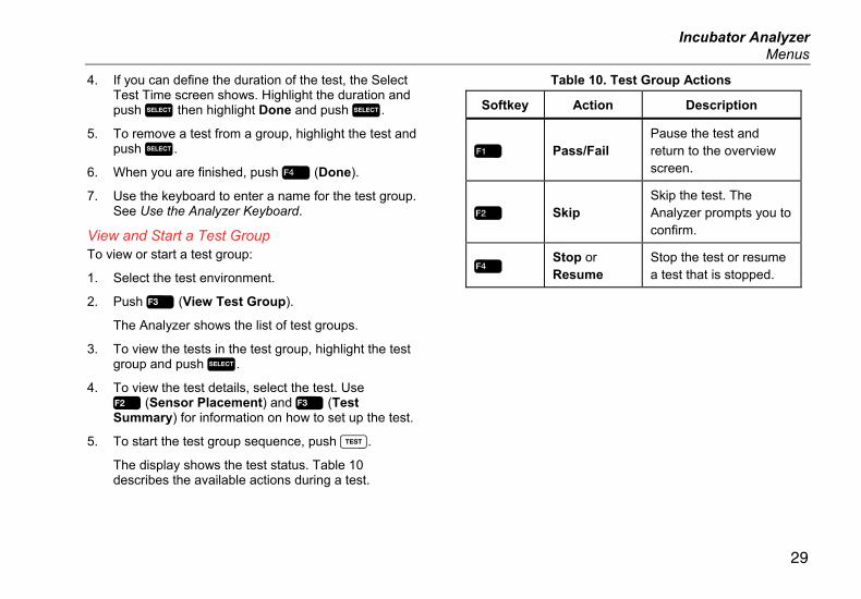
4. If you can define the duration of the test, the Select Test Time screen shows. Highlight the duration and push then highlight Done and push .
5. To remove a test from a group, highlight the test and push .
6. When you are finished, push (Done).
7. Use the keyboard to enter a name for the test group. See Use the Analyzer Keyboard.
View and Start a Test Group To view or start a test group:
1. Select the test environment.
2. Push (View Test Group).
The Analyzer shows the list of test groups.
3. To view the tests in the test group, highlight the test group and push .
4. To view the test details, select the test. Use (Sensor Placement) and (Test Summary) for information on how to set up the test.
5. To start the test group sequence, push .
The display shows the test status. Table 10 describes the available actions during a test.
Table 10. Test Group Actions
Softkey Action Description
Pass/Fail Pause the test and return to the overview screen.
Skip Skip the test. The Analyzer prompts you to confirm.
Stop or Resume
Stop the test or resume a test that is stopped.

INCU™ II Users Manual
30
Test List by Standard Table 11 is a list of tests by standard.
Table 11. List of Tests by Standard
Baby Incubator
60601-2-19
Transport Incubator
60601-2-20
Radiant Warmer
60601-2-21 Test Description
-- 201.4.10.102 --
Operating on Battery Power
Make sure the Transport Incubator can maintain the temperature on battery power for at least 30 minutes.
201.9.6.2.1.101 201.9.6.2.1.101 -- Inside — Sound Level
Measure the level of sound in the compartment.
201.9.6.2.1.102 201.9.6.2.1.102 201.9.6.2.1.101
Outside — Alarm Level
Measure the level of the audible alarm outside of the compartment.
201.9.6.2.1.103 201.9.6.2.1.103 201.9.6.2.1.101
Inside — Alarm Level
Measure the level of the audible alarm in the compartment.
201.11.1.2.2 -- --
Infant Contact Surface Temperature
Measure the temperature of each surface that the infant might touch.

Incubator Analyzer Test List by Standard
31
Table 11. List of Tests by Standard (cont.)
Baby Incubator
60601-2-19
Transport Incubator
60601-2-20
Radiant Warmer
60601-2-21 Test Description
201.12.1.101 201.12.1.101 -- Stability of Incubator Temperature (32 °C and 36 °C)
Make sure the temperature stays at the setting.
201.12.1.102 201.12.1.102 --
Uniformity of Temperature (32 °C and 36 °C)
Make sure that the temperature is the same throughout the compartment.
201.12.1.103 201.12.1.103 201.12.1.101
Skin Temperature Sensor Accuracy
Measure the skin temperature sensor with calibrated heater assembly.
201.12.1.102
Temperature Distribution Accuracy
Make sure that the average temperature of the mid-point is the same as the average of the other test points.
-- -- 201.12.1.103
Operating Temperature Accuracy
Make sure that the temperature control is the actual temperature sensed by the skin temperature probe.

INCU™ II Users Manual
32
Table 11. List of Tests by Standard (cont.)
Baby Incubator
60601-2-19
Transport Incubator
60601-2-20
Radiant Warmer
60601-2-21 Test Description
201.12.1.105 201.12.1.105 --
Accuracy of Indicator (32 °C and 36 °C)
Check the accuracy of the temperature indicated by the incubator.
201.12.1.106
201.12.1.106
(Ambient 15 °C and 25 °C)
--
Temperature Control Accuracy (32 °C)
Make sure the temperature control sets the temperature to the correct value.
201.12.1.107 201.12.1.107 --
Warm-up Time
Check that the incubator gets to the temperature in the time specified in the manual for the incubator.
201.12.1.108 201.12.1.108 --
Overshoot for Incubator Temperature
Make sure the incubator does not get too hot when warming up.
201.12.1.109 201.12.1.109 -- RH Accuracy
Check the accuracy of the relative humidity.
Incubator Analyzer Test List by Standard
33
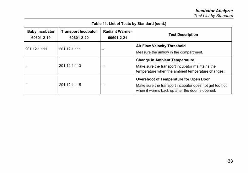
Table 11. List of Tests by Standard (cont.)
Baby Incubator
60601-2-19
Transport Incubator
60601-2-20
Radiant Warmer
60601-2-21 Test Description
201.12.1.111 201.12.1.111 -- Air Flow Velocity Threshold
Measure the airflow in the compartment.
-- 201.12.1.113 --
Change in Ambient Temperature
Make sure the transport incubator maintains the temperature when the ambient temperature changes.
-- 201.12.1.115 --
Overshoot of Temperature for Open Door
Make sure the transport incubator does not get too hot when it warms back up after the door is opened.

INCU™ II Users Manual
34
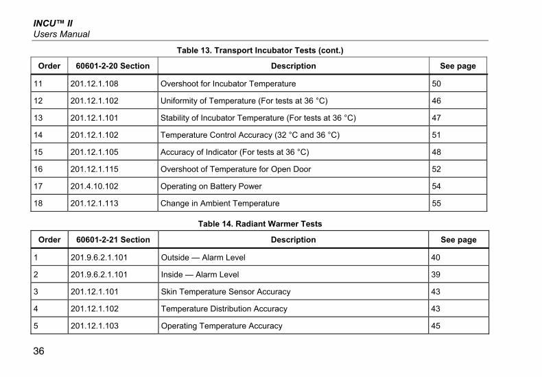
Test List by Test Order The Analyzer completes the tests in a set order to minimize the changes to the incubator temperature. Table 12 is a list of the Baby Incubator tests (60601-2-19), Table 13 is a list of the Transport Incubator tests (60601-2-20), and Table 14 is a list of Radiant Warmer tests (60601-2-21).
Table 12. Baby Incubator Tests
Order 60601-2-19 Section Description See page
1 201.12.1.107 Warm-up Time 37
2 201.9.6.2.1.101 Inside — Sound Level 38
3 201.9.6.2.1.103 Inside — Alarm Level 39
4 201.9.6.2.1.102 Outside — Alarm Level 40
5 201.12.1.111 Air Flow Velocity Threshold 41
6 201.11.1.2.2 Infant Contact Surface Temperature 42
7 201.12.1.103 Skin Temperature Sensor Accuracy 43
8 201.12.1.102 Uniformity of Temperature (For tests at 32 °C) 46
9 201.12.1.101 Stability of Incubator Temperature (For tests at 32 °C) 47
10 201.12.1.105 Accuracy of Indicator (32 °C and 36 °C) 48
11 201.12.1.109 RH Accuracy 50
12 201.12.1.108 Overshoot for Incubator Temperature 50

Incubator Analyzer Test List by Test Order
35
Table 12. Baby Incubator Tests (cont.)
Order 60601-2-19 Section Description See page
13 201.12.1.102 Uniformity of Temperature (For tests at 36 °C) 46
14 201.12.1.101 Stability of Incubator Temperature (For tests at 36 °C) 47
15 201.12.1.106 Temperature Control Accuracy 52
Table 13. Transport Incubator Tests
Order 60601-2-20 Section Description See page
1 201.12.1.107 Warm-up Time 37
2 201.9.6.2.1.101 Inside — Sound Level 38
3 201.9.6.2.1.103 Inside — Alarm Level 39
4 201.9.6.2.1.102 Outside — Alarm Level 40
5 201.12.1.111 Air Flow Velocity Threshold 41
6 201.12.1.103 Skin Temperature Sensor Accuracy 43
7 201.12.1.102 Uniformity of Temperature (For tests at 32 °C) 46
8 201.12.1.101 Stability of Incubator Temperature (32 °C) 47
9 201.12.1.105 Accuracy of Indicator (For tests at 32 °C) 48
10 201.12.1.109 RH Accuracy 50
INCU™ II Users Manual
36
Table 13. Transport Incubator Tests (cont.)
Order 60601-2-20 Section Description See page
11 201.12.1.108 Overshoot for Incubator Temperature 50
12 201.12.1.102 Uniformity of Temperature (For tests at 36 °C) 46
13 201.12.1.101 Stability of Incubator Temperature (For tests at 36 °C) 47
14 201.12.1.102 Temperature Control Accuracy (32 °C and 36 °C) 51
15 201.12.1.105 Accuracy of Indicator (For tests at 36 °C) 48
16 201.12.1.115 Overshoot of Temperature for Open Door 52
17 201.4.10.102 Operating on Battery Power 54
18 201.12.1.113 Change in Ambient Temperature 55
Table 14. Radiant Warmer Tests
Order 60601-2-21 Section Description See page
1 201.9.6.2.1.101 Outside — Alarm Level 40
2 201.9.6.2.1.101 Inside — Alarm Level 39
3 201.12.1.101 Skin Temperature Sensor Accuracy 43
4 201.12.1.102 Temperature Distribution Accuracy 43
5 201.12.1.103 Operating Temperature Accuracy 45

Incubator Analyzer Test Procedures
37
Test Procedures The Analyzer completes the tests in a set order to minimize the changes to the incubator temperature. See the Test List by Test Order section for a list of all tests in the order they are executed.
Warm-up Time
201.12.1.107 (Baby Incubator)
201.12.1.107 (Transport Incubator) Use this test to make sure the warm-up time stated in the DUT manual is accurate.
Pass Criteria To pass, the temperature must increase by 11 °C in ±20 % of time given in the DUT manual.
Prepare for the Test To get accurate test results:
• Start with the DUT off and at ambient temperature.
• Set the DUT to air-controlled operation.
• Make sure the water level is normal and the water is also at ambient temperature.
Procedure 1. Turn off the DUT.
2. Make sure the DUT and the water tank are at ambient temperature.
3. On the Analyzer:
a. Select the test environment.
b. Select Warm-up Time.
c. Push and enter the warm-up time given in the user documentation of the DUT. When you are finished push (Done).
d. Connect the T5 probe to the Analyzer and put the probe in the center of the Analyzer. (See Figure 8.)
e. Put the Analyzer at the center of the mattress.
f. Push .
The Analyzer measures the ambient temperature and prompts you to set the DUT to the appropriate temperature.

INCU™ II Users Manual
38
4. Turn on the DUT and:
a. Set the temperature control to the temperature indicated by the Analyzer.
b. Set the humidity control to maximum humidity.
5. On the Analyzer, push .
Note
For best results, minimize the time between turning on the DUT and pushing .
6. Close the compartment.
The Analyzer measures the time it takes to reach the given temperature and then shows the results.
Inside — Sound Level
201.9.6.2.1.101 (Baby Incubator)
201.9.6.2.1.101 (Transport Incubator) This test checks the sound level inside of the compartment.
Pass Criteria To pass, the sound in the compartment must be ≤60 dBA. The background sound must also be ≤10 dBA of the measured sound.
Prepare for the Test To get accurate test results:
• Put the DUT in quiet ambient environment in a reflective room.
• Start with the alarms turned off.
Procedure 1. Turn off the DUT.
2. On the Analyzer:
a. Select the test environment.
b. Select Inside—Sound Level.
c. Connect the sound probe to the Analyzer and put the probe in the center of the Analyzer. (See Table 7.)
d. Put the Analyzer at the center of the mattress.
e. Push .
3. On the DUT:
a. Close the compartment.
Wait for the Analyzer to measure the background sound level. The Analyzer prompts you to continue the test.

Incubator Analyzer Test Procedures
39
b. Turn on the DUT. The DUT should be in normal operation.
c. Set the controls to 36 °C and maximum humidity.
4. On the Analyzer, push to continue. The Analyzer starts a countdown to the measurement.
5. Close the compartment and wait for the Analyzer to do the test.
The Analyzer takes the measurement after the delay time and then shows the results.
Inside — Alarm Level
201.9.6.2.1.103 (Baby Incubator)
201.9.6.2.1.103 (Transport Incubator)
201.9.6.2.1.101 (Radiant Warmer) This test measures the level of the audible alarm inside of the compartment.
Pass Criteria To pass, the alarm sound must be ≥10 dBA above background sound and the alarm sound is ≤80 dBA.
Prepare for the Test To get accurate test results:
• Put the DUT in quiet ambient environment in a reflective room.
• Start with the alarms turned off.
Note
The 201.9.6.2.1.101 (Audible alarms sound level) test in IEC 60601-2-21 measures sound from a height of 5 cm above the mattress. On the Analyzer, the height of the probe is 10 cm above the mattress. Fluke Biomedical finds no difference in sound levels between 5 cm and 10 cm and considers the heights equivalent for this test.
Procedure For each selectable alarm frequency:
1. On the Analyzer:
a. Select the test environment.
b. Select Inside— Alarm Level.
c. Connect the sound probe to the Analyzer and put the probe in the center of the Analyzer. (See Table 7.)
INCU™ II Users Manual
40
d. Put the Analyzer at the center of the mattress.
e. Push .
Wait for the Analyzer to measure the background sound level. When the background measurement is complete, the Analyzer prompts you to turn on the alarm.
f. Push to continue. The Analyzer starts a countdown to the measurement.
2. On the DUT:
a. Close the compartment, if necessary.
b. Set the controls to 36 °C and maximum humidity.
c. Activate the alarm. If alarm is adjustable it must be set to at least 50 dbA. The Analyzer takes the measurement.
3. When the Analyzer shows the results, turn off the alarm.
Outside — Alarm Level
201.9.6.2.1.102 (Baby Incubator)
201.9.6.2.1.102 (Transport Incubator)
201.9.6.2.1.101 (Radiant Warmer) This test measures the level of the audible alarm outside of the compartment.
Pass Criteria To pass, the alarm sound must be ≥10 dBA above the background sound level and ≥65 dBA (for non-adjustable alarms) or ≥50 dBA (at the lowest adjustable setting).
Prepare for the Test To get accurate test results:
• Put the DUT in quiet ambient environment in a reflective room.
• Repeat the test for each of the selectable frequencies.

Incubator Analyzer Test Procedures
41
Procedure For each selectable alarm frequency:
1. Put the sound probe 1.5 m above the floor and 3 m in front of the DUT.
2. On the DUT, set the controls to 36 °C and maximum humidity.
3. On the Analyzer:
a. Select the test environment.
b. Select Outside—Alarm Level.
c. Put the Analyzer in the compartment.
d. Push .
4. Close the compartment if necessary.
Wait for the Analyzer to measure the background sound level. When the background sound measurement is complete, the Analyzer prompts you to activate the incubator alarm.
5. On the Analyzer, push to continue.
6. On the DUT:
a. Close the compartment, if necessary.
b. Activate the alarm. If alarm is adjustable it must be set to at least 50 dbA.
The Analyzer takes the measurement.
7. When the Analyzer shows the results, turn off the Alarm.
Air Flow Velocity Threshold
201.12.1.111 (Baby Incubator)
201.12.1.111 (Transport Incubator) This test measures the air velocity inside the compartment.
Pass Criteria To pass, the velocity must be ≤0.35 m/s at each location that you measure.
Prepare for the Test To get accurate test results:
• Make sure there is enough time for the Air Flow probe to stabilize at the ambient temperature.
• Make measurements from the center of the mattress and from the center of each quadrant. Use the placement pad for consistency.

INCU™ II Users Manual
42
Procedure For the first measurement, put the probe in the center of the mattress. For the next measurement, put the probe in the center of the first quadrant. Continue taking measurements at the center of each quadrant, in a clockwise direction.
1. On the Analyzer:
a. Select the test environment.
b. Select Air Velocity Threshold.
c. Put the placement pad on the mattress.
d. Connect the Air Flow probe to the Analyzer and put the probe in the center of the Analyzer. (See Table 7.)
e. Put the Analyzer in the center of the mattress.
f. Push .
2. On the DUT:
a. Close the compartment.
b. Set the controls to 36 °C and maximum humidity.
The Analyzer waits for the airflow to stabilize and then does the measurement. When the measurement is complete, the Analyzer prompts you to move the probe to the next location.
3. Put the probe on a tripod and put the tripod in the next location and then push to continue.
4. On the Analyzer, push .
5. On the DUT, close the compartment.
When the test is done, the Analyzer shows the results.
Infant Contact Surface Temperature
201.11.1.2.2 (Baby Incubator) This test checks all the surfaces that might touch the infant and makes sure the surfaces do not get too hot.
Pass Criteria To pass, the applied parts must be ≤40 °C. The temperature of any metal that can touch the infant must be ≤40 °C. The temperature of all other surfaces that can touch the infant must be ≤43 °C.
Prepare for the Test To get accurate test results:
• Use a thermal compound to ensure good contact between the surface and the thermocouple.
• Repeat the test for each surface that can touch the infant.
Incubator Analyzer Test Procedures
43
Procedure 1. On the DUT, set the controls to the maximum
temperature.
2. On the Analyzer:
a. Select the test environment.
b. Select Infant Contact Surface Temperature.
c. Select how the surface touches the infant:
• Direct Contact – for applied parts
• Accessible – for surfaces that can touch the infant
d. Select the type of material to test:
• Metal
• Other Material
3. Attach the K-type thermocouple to the location with a thermal compound.
4. On the Analyzer, push and then close the compartment on the DUT.
The Analyzer starts the countdown clock and does the temperature measurement. When the test is done, the Analyzer shows the results.
Skin Temperature Sensor Accuracy
201.12.1.103 (Baby Incubator)
201.12.1.103 (Transport Incubator)
201.9.6.2.1.101 (Radiant Warmer)
Note
Requires the optional Skin Temperature Assembly.
For more information, see the instructions that come with the Skin Temperature Heater Assembly.
Temperature Distribution Accuracy
201.9.6.2.1.102 (Radiant Warmer) This test compares the temperature of the mid-point to the temperature of other points in the warmer.
Pass Criteria To pass, the average temperature of the mid-point temperatures must be within 2 °C of the other test points.
Prepare for the Test To get accurate test results:
• Make sure the ambient temperature is 23.0 °C (±2.0).
• Make sure the air velocity is <0.1 m/s.
INCU™ II Users Manual
44
• If possible, set the DUT to baby-controlled.
• The test does not start until the DUT is at STC.
Note
The longer you wait to start the test after STC, the more stable the radiant warmer environment becomes. A more stable environment gives a more accurate reading. This is due to the radiant warmer environment and not the accuracy of the Analyzer.
Procedure 1. Put the DUT in a room where the ambient
temperature is 23.0 °C (±2.0).
2. On the Analyzer:
a. Select the test environment.
b. Select Temperature Distribution Accuracy.
c. To change the test time, push (Test Time) and select the time. The default test time is 60 minutes.
d. Put the placement pad on the mattress.
e. Connect the pucks to the Analyzer.
f. Put the Analyzer in the center of the mattress.
g. Put the T5 puck at center of the Analyzer.
h. Put T1, T2, T3 and T4 pucks in the center of each quadrant. Use the placement pad as a guide.
i. Push .
3. On the DUT:
a. Close the compartment (if necessary).
b. Set the temperature to 36 °C.
The Analyzer takes measurements until the DUT reaches STC. This takes at least one hour. When the Analyzer detects STC, the Analyzer continues to measure for the test time.
When the test is done, the Analyzer shows the results.
Incubator Analyzer Test Procedures
45
Operating Temperature Accuracy
201.12.1.103 (Radiant Warmer) This test compares the temperature control to the actual indication from the skin temperature probe.
Pass Criteria To pass, the skin temperature probe and the temperature control must be within 0.5 °C.
Prepare for the Test To get accurate test results:
• Make sure the ambient temperature is 23.0 °C (±2.0).
• Make sure the air velocity is less than 0.1 m/s.
• If possible, set the DUT to baby-controlled.
• The skin temperature sensor must make good thermal contact with the puck.
• Put the mattress in the horizontal position.
• The test does not start until the DUT is at STC.
Note
The longer you wait to start the test after STC, the more stable the radiant warmer environment becomes. A more stable environment gives a more accurate reading. This is due to the radiant warmer environment and not the accuracy of the Analyzer.
Procedure 1. Put the radiant warmer in a room with the ambient
temperature is 23.0 °C (±2.0).
2. On the Analyzer:
a. Select the test environment.
b. Select Operating Temperature Accuracy.
c. To change the test time, push (Test Time) and select the time. The default test time is 60 minutes.
INCU™ II Users Manual
46
d. Connect the skin temperature probes to the T5 puck.
e. Put the puck on the center of the Analyzer and put the Analyzer at the center of the mattress.
f. Push .
3. On the DUT:
a. Close the compartment (if necessary)
b. Set the temperature to 36 °C.
The Analyzer takes measurements until the DUT reaches STC. This takes at least one hour. When the Analyzer detects STC, the Analyzer continues to measure for the test time. The Analyzer prompts you to enter the temperature shown on the incubator.
4. On the Analyzer, use and to enter the temperature and then select Done.
When the test is done, the Analyzer shows the results.
Uniformity of Temperature
201.12.1.102 (Baby Incubator)
201.12.1.102 (Transport Incubator) This test makes sure the temperature is the same throughout the incubator.
Pass Criteria Baby Incubator: To pass, the average temperature of each of the quadrants must be within 0.8 °C of the midpoint or within 1.0 °C if the mattress is tilted.
Transport Incubator: To pass, the average temperature of each of the quadrants must be within 1.5 °C of the midpoint or within 2.0 °C if the mattress is tilted.
Prepare for the Test To get accurate test results:
• Repeat the test with the mattress in the horizontal position and at the extremes of the tilt angle.
Note
You can create a test group to repeat the test for each tilt angle. If you must open the incubator to change the tilt level, then the incubator must get to STC before the test.
• Set the DUT to air-controlled operation.
• The test does not start until the DUT is at STC.

Incubator Analyzer Test Procedures
47
Procedure 1. On the DUT, adjust the mattress to the horizontal
position.
2. On the Analyzer:
a. Select the test environment.
b. Select Uniformity of Temperature.
c. To change the test time, push (Test Time) and select the time. The default test time is 30 minutes.
d. Select the test temperature as 32 °C or 36 °C.
e. Select the mattress tilt.
f. Put the placement pad on the mattress.
g. Connect the T5 probe to the Analyzer and put the probe in the center of the Analyzer. (See Figure 7.)
h. Put the Analyzer at the center of the mattress.
i. Connect the T1, T2, T3 and T4 probes to the Analyzer and put them in position on the placement pad.
3. Set the DUT to the test temperature.
4. On the Analyzer, push and close the compartment on the DUT.
When the test is done, the Analyzer shows the results.
Stability of Incubator Temperature
201.12.1.102 (Baby Incubator)
201.12.1.102 (Transport Incubator) This test makes sure that the incubator can stay at a consistent temperature for at least one hour.
Pass Criteria Baby Incubator: The average temperature = any temperature reading ±0.5 °C.
Transport Incubator: The average temperature = any temperature reading ±1.0 °C.
Prepare for the Test To get accurate test results:
• The test does not start until the DUT is at STC.
• Run the test at control temperatures of 32 °C and 36 °C.

INCU™ II Users Manual
48
Procedure 1. On the incubator, adjust the mattress to the
horizontal position.
2. On the Analyzer:
a. Select the test environment.
b. Select Stability of Incubator Temperature.
c. To change the test time, push (Test Time) and select the time. The default test time is 60 minutes.
d. Connect the T5 probe to the Analyzer and put the probe in the center of the Analyzer. (See Figure 7.)
e. Put the Analyzer at the center of the mattress.
3. Set the DUT to the test temperature.
4. On the Analyzer, push .
5. Close the DUT.
The Analyzer takes measurements to make sure the DUT reaches STC. This takes at least one hour. When the Analyzer detects STC, the Analyzer continues to measure for the test time.
6. Use and to enter the temperature and then select Done.
When the test is done, the Analyzer shows the results.
Incubator Analyzer Test Procedures
49
Accuracy of Indicator
201.12.1.105 (Baby Incubator)
201.12.1.105 (Transport Incubator) This test makes sure the temperature indicated by the incubator is the actual incubator temperature.
Pass Criteria Baby Incubator: The average temperature = the temperature indication ±0.8 °C.
Transport Incubator: The average temperature = the temperature indication ±1.5 °C.
Prepare for the Test To get accurate test results:
• The test does not start until the DUT is at STC.
• For an accurate test you must calculate the average temperature of the indication shown on the DUT after the test starts.
• Run the test at control temperatures of 32 °C and 36 °C.
Procedure 1. On the Analyzer:
a. Select the test environment.
b. Select Accuracy of Indicator.
c. To change the test time, push (Test Time) and select the time. The default test time is 60 minutes.
d. Connect the T5 probe to the Analyzer and put the probe in the center of the Analyzer. (See Table 7.)
e. Put the Analyzer at the center of the mattress.
2. On the Analyzer, select the test temperature as 32 °C or 36 °C.
3. Set the incubator to the test temperature.
4. On the Analyzer, push .
5. Close the DUT.
The Analyzer takes measurements to make sure the incubator reaches STC. This takes at least one hour.

INCU™ II Users Manual
50
6. Track the indication on the incubator display at regular intervals and calculate the average.
7. Use and to enter the average temperature you have calculated from the display temperature and then push .
When the test is done, the Analyzer shows the results.
RH Accuracy
201.12.1.109 (Baby Incubator)
201.12.1.109 (Transport Incubator) This test checks the humidity level throughout the incubator.
Pass Criteria Baby Incubator: The incubator value = tester value ±10 %
Transport Incubator: The incubator value = tester value ±15 %.
Procedure 1. On the Analyzer:
a. Select the test environment.
b. Select RH Accuracy.
2. Connect the humidity probe to the Analyzer and put the probe in the center of the Analyzer. (See Table 7.)
3. Put the Analyzer at the center of the mattress.
4. Set the incubator control between 32 °C and 36 °C.
5. On the Analyzer, push .
6. Close the DUT.
The Analyzer measures the humidity. The Analyzer prompts you to enter the humidity indication.
7. On the Analyzer, use and to enter the humidity indication on the incubator and then push .
When the test is done, the Analyzer shows the results.
Incubator Analyzer Test Procedures
51
Overshoot for Incubator Temperature
201.12.1.108 (Baby Incubator)
201.12.1.108 (Transport Incubator) This test makes sure the temperature increases in time without going over 38 °C.
Pass Criteria Baby Incubator: Make sure that when the temperature is increased from 32 °C to 36 °C the incubator stays ≤38 °C. In 15 minutes, the temperature must get to 36 °C and be stable enough to start the STC measurement.
Transport Incubator: Make sure that when the temperature is increased from 32 °C to 36 °C the incubator stays ≤38 °C.
Prepare for the Test To get accurate test results:
• Set the DUT to air-controlled operation.
• The test does not start until the DUT is at STC.
• The test does not start unless the temperature reaches at least 36 °C.
Procedure 1. On the Analyzer:
a. Select the test environment.
b. Select Overshoot of Incubator Temperature.
2. Connect the T5 probe to the Analyzer and put the probe in the center of the Analyzer. (See Table 7.)
3. Put the Analyzer at the center of the mattress.
4. Close the compartment.
5. Set the DUT to the test temperature 32 °C.
6. On the Analyzer, push .
7. Close the incubator.
The Analyzer takes measurements to make sure the DUT reaches STC. This takes at least one hour. When the Analyzer detects STC, the Analyzer prompts you to set the DUT temperature.
8. Set the incubator to 36 °C.
The test continues automatically when the DUT reaches 36 °C. The test continues until the DUT reaches STC. When the test is done, the Analyzer shows the results.

INCU™ II Users Manual
52
Temperature Control Accuracy
201.12.1.106 (Baby Incubator)
201.12.1.106 (Transport Incubator) This test makes sure the temperature control setting sets an accurate temperature in the DUT. For a transport incubator, the test checks the accuracy at different ambient temperatures.
Pass Criteria Baby Incubator: The incubator control setting = the tester measurement ±1.5 °C.
Transport Incubator: To pass, the average temperature of each of the quadrants must be within 1.5 °C of the midpoint or within 2.0 °C if the mattress is tilted.
Prepare for the Test To get accurate test results:
• The test does not start until the DUT is at STC.
• Set the DUT to air-controlled operation.
• For the transport incubator, do one test at an ambient temperature of 15 °C and one at an ambient temperature of 25 °C.
Procedure 1. For a transport incubator, put the DUT in a room
where ambient temperature is controlled. Complete one test at 15 °C and one test at 25 °C.
2. On the Analyzer:
a. Select the test environment.
b. Select Temperature Control Accuracy.
c. For a transport incubator, select the ambient temperature.
d. To change the test time, push (Test Time) and select the time. The default test time is 30 minutes.
3. Connect the T5 probe to the Analyzer and put the probe in the center of the Analyzer. (See Figure 7.)
4. Put the Analyzer at the center of the mattress.
5. Set the DUT to the test temperature.
6. On the Analyzer, push .
7. Close the DUT.
The Analyzer takes measurements to make sure the incubator reaches STC. This takes at least one hour.
When the test is done, the Analyzer shows the results.

Incubator Analyzer Test Procedures
53
Overshoot of Temperature for Open Door
201.12.1.115 (Transport Incubator) This test makes sure the temperature increases in time without going over 38 °C.
Pass Criteria Make sure that when the temperature is set to 36 °C the incubator stays ≤38 °C even if the DUT door opens for 10 minutes.
Prepare for the Test To get accurate test results:
• Set the DUT to air-controlled operation.
• Do not open the door on the DUT until the DUT is at STC.
• After the door on the DUT is closed, let the test run long enough to determine whether overshoot occurs.
Procedure 1. On the Analyzer:
a. Select the test environment.
b. Select Overshoot of Temperature for Open Door.
c. To change the test time, push (Test Time) and select the time. The default test time is 30 minutes.
2. Connect the T5 probe to the Analyzer and put the probe in the center of the Analyzer. (See Figure 7.)
3. Put the Analyzer at the center of the mattress.
4. On the Analyzer, push .
5. Close the compartment.
6. Set the DUT to the test temperature 36 °C.
The Analyzer takes measurements to ensure the incubator reaches STC. This takes at least one hour. When the Analyzer detects STC, the Analyzer prompts you to open the incubator access doors.
7. Open the DUT access doors.
8. After 10 minutes, select OK on the Analyzer and close the DUT access doors.
When the test is done, the Analyzer shows the results.
INCU™ II Users Manual
54
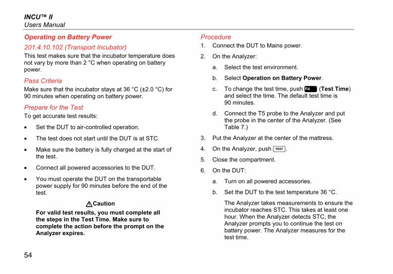
Operating on Battery Power
201.4.10.102 (Transport Incubator) This test makes sure that the incubator temperature does not vary by more than 2 °C when operating on battery power.
Pass Criteria Make sure that the incubator stays at 36 °C (±2.0 °C) for 90 minutes when operating on battery power.
Prepare for the Test To get accurate test results:
• Set the DUT to air-controlled operation.
• The test does not start until the DUT is at STC.
• Make sure the battery is fully charged at the start of the test.
• Connect all powered accessories to the DUT.
• You must operate the DUT on the transportable power supply for 90 minutes before the end of the test.
WCaution
For valid test results, you must complete all the steps in the Test Time. Make sure to complete the action before the prompt on the Analyzer expires.
Procedure 1. Connect the DUT to Mains power.
2. On the Analyzer:
a. Select the test environment.
b. Select Operation on Battery Power.
c. To change the test time, push (Test Time) and select the time. The default test time is 90 minutes.
d. Connect the T5 probe to the Analyzer and put the probe in the center of the Analyzer. (See Table 7.)
3. Put the Analyzer at the center of the mattress.
4. On the Analyzer, push .
5. Close the compartment.
6. On the DUT:
a. Turn on all powered accessories.
b. Set the DUT to the test temperature 36 °C.
The Analyzer takes measurements to ensure the incubator reaches STC. This takes at least one hour. When the Analyzer detects STC, the Analyzer prompts you to continue the test on battery power. The Analyzer measures for the test time.

Incubator Analyzer Test Procedures
55
7. When prompted, remove the DUT from Mains power. The incubator must remain on battery power for 90 minutes.
When the test is done, the Analyzer shows the results.
Change in Ambient Temperature
201.12.1.113 (Transport Incubator) This test makes sure that the incubator temperature does not vary by more than 3 °C even if the ambient temperature changes.
Pass Criteria Make sure that the incubator stays at 36 °C (±3.0 °C) as it is moved from 25 °C to -5 °C.
Prepare for the Test To get accurate test results:
• Fully charge the DUT battery prior to the test.
• Set the DUT to air-controlled operation.
• The test does not start until the DUT is at STC.
• The test requires a room with ambient temperature of -5 °C (±2 °C) and the air velocity ≤1 m/s. (The DUT will be on battery power.)
• The test requires a room with ambient temperature of 21 °C to 25 °C and the air velocity ≤1 m/s. (The DUT is connected to Mains power.)
WCaution
For valid test results, you must complete all the steps in the Test Time. Make sure monitor the status of STC.
Procedure 1. Put the DUT in a room with an ambient temperature
between 20 °C and 25 °C.
2. On the Analyzer:
a. Select the test environment.
b. Select Change in Ambient Temperature.
c. To change the test time, push (Test Time) and select the time. The default test time is 60 minutes.
d. Connect the T5 probe to the Analyzer and put the probe in the center of the Analyzer.
e. Put the Analyzer at the center of the mattress
f. Push .
3. Close the compartment.
4. Set the DUT to the test temperature 36 °C.
The Analyzer takes measurements to ensure the DUT reaches STC. This takes at least one hour.
The Analyzer measures for the test time.

INCU™ II Users Manual
56
5. After the DUT reaches STC, remove the DUT from Mains power.
6. Put the DUT in a room that is -5 °C (±2 °C) for a minimum of 15 minutes.
7. After 15 minutes, put the DUT in a room with an ambient temperature between 20 °C and 25 °C.
8. Reconnect the DUT to Mains power.
When the test is done, the Analyzer shows the results.
Maintenance and Troubleshooting
XW Warning
To prevent possible electrical shock, fire, or personal injury:
• Repair the Product before use if the battery leaks.
• Be sure that the battery polarity is correct to prevent battery leakage.
• Use only Fluke approved power adapters to charge the battery.
• Batteries contain hazardous chemicals that can cause burns or explode. If exposure to chemicals occurs, clean with water and get medical aid.
• Do not disassemble the battery.
• Do not disassemble or crush battery cells and battery packs.
• Do not put battery cells and battery packs near heat or fire. Do not put in sunlight.
Incubator Analyzer Maintenance and Troubleshooting
57
• Do not short the battery terminals together.
• Do not keep cells or batteries in a container where the terminals can be shorted.
• Remove the input signals before you clean the Product.
• Use only specified replacement parts.
• Have an approved technician repair the Product.
• Disconnect the battery charger and move the Product or battery to a cool, non-flammable location if the rechargeable battery becomes hot (>50 °C) during the charge period.
• Replace the rechargeable battery after 5 years of moderate use or 2 years of heavy use. Moderate use is defined as recharged twice a week. Heavy use is defined as discharged to cut off and recharged daily.
• Verify the safe state of the equipment after repair.
• Recycle spent batteries according to local ordinances.
WCaution
Changes or modifications not expressly approved by Fluke could void the user's authority to operate the equipment.
After maintenance, check the Analyzer for safe operation. Check all cables and connections for damage or wear. Replace any damaged components before use.
Clean the Analyzer The Analyzer needs little maintenance or special care. Treat the Analyzer and probes as calibrated measurement instruments. Avoid dropping or other mechanical abuse.
To clean the Analyzer, wipe with a damp cloth. Do not allow liquid to get into the Analyzer.
Wipe down the probes and cables with the same care.
Set the Calibration Factors If you get a replacement probe or puck, you must set the calibration factors:
1. Push .
2. Use and to highlight Instrument Information and then push .
3. Highlight Probe Information and then push .
4. Highlight the sensor and then push .
5. Use the numeric keyboard to enter the calibration factor that came with the sensor. When you are finished push (Done).

INCU™ II Users Manual
58
Troubleshooting Table 15 lists common problems and solutions.
Table 15. Troubleshooting
Symptom Resolution
The Analyzer does not show the Top Menu.
Connect the Analyzer to Power and make sure the battery is charged.
The Analyzer fails during the initial self-test.
Contact Fluke Biomedical Technical Support
The readings are inaccurate.
Make sure the probes are plugged into the correct plug. Make sure the probe calibration factors are correct.
Radio Frequency Certification For more information, go to www.flukebiomedical.com and search for Radio Frequency Data for Class A.
See Setup Communications for instructions on how to enable the radio.

Incubator Analyzer Maintenance and Troubleshooting
59
Replaceable Parts and Accessories Table 16 is a list of replaceable parts for the Analyzer.
Table 16. Replaceable Parts
Item Fluke Biomedical Part Number
Carrying Case 4715749
Carrying Case (Pucks) 4724692
Power Adapter – Universal Voltage, 100 V to 240 V with adapters 4721194
USB Cable (Type A to Micro-B) 2m 4721166
Placement Pad 4715713
Tripod set of 4 4721109
INCU II Getting Started Manual 4715708
INCU II Users Manual CD 4715690
Radiant Warmer Pucks set of 5
Red 4721111
Yellow 4721130
White 4721148
Blue 4721153
Green 4721127
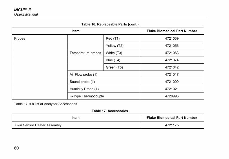
INCU™ II Users Manual
60
Table 16. Replaceable Parts (cont.)
Item Fluke Biomedical Part Number
Probes
Temperature probes
Red (T1) 4721039
Yellow (T2) 4721056
White (T3) 4721063
Blue (T4) 4721074
Green (T5) 4721042
Air Flow probe (1) 4721017
Sound probe (1) 4721000
Humidity Probe (1) 4721021
K-Type Thermocouple 4720996
Table 17 is a list of Analyzer Accessories.
Table 17. Accessories
Item Fluke Biomedical Part Number
Skin Sensor Heater Assembly 4721175
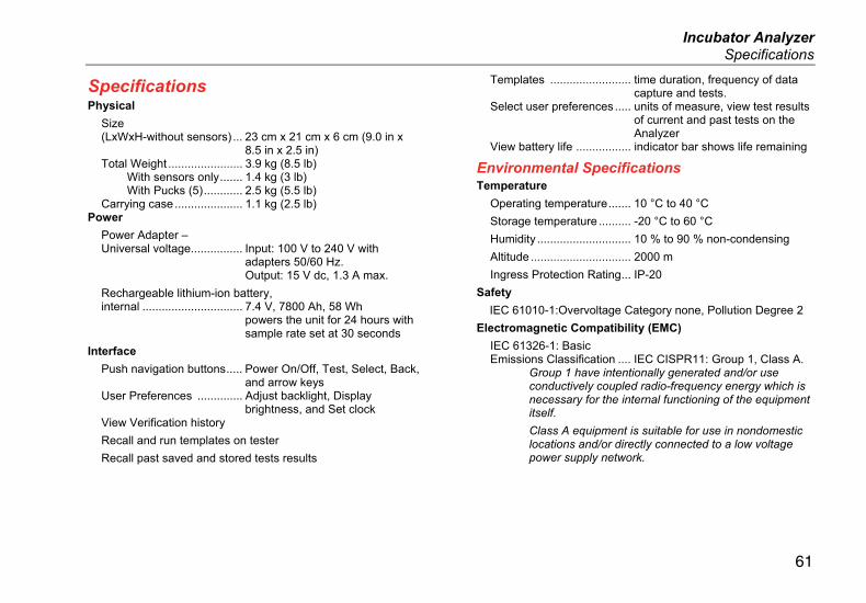
Incubator Analyzer Specifications
61
Specifications Physical
Size (LxWxH-without sensors) ... 23 cm x 21 cm x 6 cm (9.0 in x
8.5 in x 2.5 in) Total Weight ....................... 3.9 kg (8.5 lb)
With sensors only ....... 1.4 kg (3 lb) With Pucks (5) ............ 2.5 kg (5.5 lb)
Carrying case ..................... 1.1 kg (2.5 lb) Power
Power Adapter – Universal voltage................ Input: 100 V to 240 V with
adapters 50/60 Hz. Output: 15 V dc, 1.3 A max.
Rechargeable lithium-ion battery, internal ............................... 7.4 V, 7800 Ah, 58 Wh
powers the unit for 24 hours with sample rate set at 30 seconds
Interface
Push navigation buttons ..... Power On/Off, Test, Select, Back, and arrow keys
User Preferences .............. Adjust backlight, Display brightness, and Set clock
View Verification history
Recall and run templates on tester
Recall past saved and stored tests results
Templates ......................... time duration, frequency of data capture and tests.
Select user preferences ..... units of measure, view test results of current and past tests on the Analyzer
View battery life ................. indicator bar shows life remaining
Environmental Specifications Temperature
Operating temperature ....... 10 °C to 40 °C
Storage temperature .......... -20 °C to 60 °C
Humidity ............................. 10 % to 90 % non-condensing
Altitude ............................... 2000 m
Ingress Protection Rating ... IP-20
Safety
IEC 61010-1:Overvoltage Category none, Pollution Degree 2
Electromagnetic Compatibility (EMC)
IEC 61326-1: Basic Emissions Classification .... IEC CISPR11: Group 1, Class A.
Group 1 have intentionally generated and/or use conductively coupled radio-frequency energy which is necessary for the internal functioning of the equipment itself.
Class A equipment is suitable for use in nondomestic locations and/or directly connected to a low voltage power supply network.

INCU™ II Users Manual
62
USA (FCC) ......................... Intentional Radiators This device complies with part 15 of the FCC Rules. Operation is subject to the following two conditions: (1) This device may not cause harmful interference, and (2) this device must accept any interference received, including interference that may cause undesired operation.(15.19)
Korea (KCC) ....................... Class A Equipment (Industrial Broadcasting & Communication Equipment)
Class A: Equipment meets requirements for industrial electromagnetic wave equipment and the seller or user should take notice of it. This equipment is intended for use in business environments and not to be used in homes.
Wireless Module Listing
FCC (United States) compliant (Class A) ............................. FCC ID: X3ZBTMOD3
IC (Industry Canada) compliant ............................ IC: 8828A-MOD3
CE (European) certified ...... CE0051
802.15.1 qualified ............... QD ID: B019224
Wireless Radio
Frequency range ................. 2412 to 2483 MHz Output Power ...................... 10 mW
Measurements and Test Specifications 5 Air Convection Temperature for Incubator – Sensors in probes (T1-T5) ................................ 0 °C to 50 °C
Accuracy ....................... ± 0.05 °C Display Resolution ........ 0.01 °C
5 Air Convection Temperature for Radiant Warmers – Sensors in pucks (Black discs) ....................... 0 °C to 50 °C
Accuracy ....................... ±0.2 °C Display Resolution ........ 0.01 °C
Relative Humidity ................ 0 % to 100 % Accuracy ....................... ±3 % RH (0 % to 100 %, non-
condensing) Display Resolution ........ 0.1 % RH
Air Flow ............................... 0.2 m/sec to 2.0 m/sec at 35 °C, 50 % RH
Accuracy ....................... ±0.1 m/sec Display Resolution ........ 0.01 m/sec
Sound Pressure – (Class II) ............................. 30 dB(A) to 100 dB(A)
Accuracy ....................... ±5 dB(A) Display Resolution ........ 0.1 dB(A)
IEC-61672-1 Class 2 from 31.5 Hz to 8 kHz
Surface temperature ........... -5 °C to 60 °C Accuracy ....................... ±0.5 °C Display Resolution ........ 0.05 °C