
Increasing Pose Comprehension through Augmented Reality Reenactment · 2017-11-30 · Increasing...
21
Multimedia Tools and Applications manuscript No. (will be inserted by the editor) Increasing Pose Comprehension through Augmented Reality Reenactment Fabian Lorenzo Dayrit · Yuta Nakashima · Tomokazu Sato · Naokazu Yokoya Received: date / Accepted: date Abstract Standard video does not capture the 3D aspect of human motion, which is important for comprehension of motion that may be ambiguous. In this paper, we apply augmented reality (AR) techniques to give viewers insight into 3D motion by allowing them to manipulate the viewpoint of a motion sequence of a human actor using a handheld mobile device. The motion sequence is captured using a single RGB-D sensor, which is easier for a general user, but presents the unique challenge of synthesizing novel views using images captured from a single view- point. To address this challenge, our proposed system reconstructs a 3D model of the actor, then uses a combination of the actor’s pose and viewpoint similarity to find appropriate images to texture it. The system then renders the 3D model on the mobile device using visual SLAM to create a map in order to use it to estimate the mobile device’s camera pose relative to the original capturing envi- ronment. We call this novel view of a moving human actor a reenactment, and evaluate its usefulness and quality with an experiment and a survey. Keywords Augmented reality · Mobile · Novel view synthesis · Reenactment 1 Introduction For people trying to learn actions or watch some performances, directly observing an instructor or performer who is performing the action can provide the most immersive experience. Furthermore, they have the freedom to watch the instructor or performer from any viewpoint they desire; a viewer can move around to see different sides, stand on tiptoes to watch from above, and so on. However, this requires the viewer and the instructor/performer to be present at the same time and the same place, which is not always convenient. F. Dayrit ( ) · Y. Nakashima · T.Sato · N. Yokoya Nara Institute of Science and Technology 8916-5 Takayama, Ikoma, Nara, Japan 630-0192 Tel.: +81-(0743)-72-5296 Fax: +81-(0743)-72-5299 E-mail: [email protected]
Transcript of Increasing Pose Comprehension through Augmented Reality Reenactment · 2017-11-30 · Increasing...

Multimedia Tools and Applications manuscript No.(will be inserted by the editor)
Increasing Pose Comprehension through AugmentedReality Reenactment
Fabian Lorenzo Dayrit · Yuta Nakashima ·Tomokazu Sato · Naokazu Yokoya
Received: date / Accepted: date
Abstract Standard video does not capture the 3D aspect of human motion, whichis important for comprehension of motion that may be ambiguous. In this paper,we apply augmented reality (AR) techniques to give viewers insight into 3D motionby allowing them to manipulate the viewpoint of a motion sequence of a humanactor using a handheld mobile device. The motion sequence is captured using asingle RGB-D sensor, which is easier for a general user, but presents the uniquechallenge of synthesizing novel views using images captured from a single view-point. To address this challenge, our proposed system reconstructs a 3D model ofthe actor, then uses a combination of the actor’s pose and viewpoint similarityto find appropriate images to texture it. The system then renders the 3D modelon the mobile device using visual SLAM to create a map in order to use it toestimate the mobile device’s camera pose relative to the original capturing envi-ronment. We call this novel view of a moving human actor a reenactment, andevaluate its usefulness and quality with an experiment and a survey.
Keywords Augmented reality · Mobile · Novel view synthesis · Reenactment
1 Introduction
For people trying to learn actions or watch some performances, directly observingan instructor or performer who is performing the action can provide the mostimmersive experience. Furthermore, they have the freedom to watch the instructoror performer from any viewpoint they desire; a viewer can move around to seedifferent sides, stand on tiptoes to watch from above, and so on. However, thisrequires the viewer and the instructor/performer to be present at the same timeand the same place, which is not always convenient.
F. Dayrit (�) · Y. Nakashima · T.Sato · N. YokoyaNara Institute of Science and Technology8916-5 Takayama, Ikoma, Nara, Japan 630-0192Tel.: +81-(0743)-72-5296Fax: +81-(0743)-72-5299E-mail: [email protected]

2 Fabian Lorenzo Dayrit et al.
One alternative that relaxes this limitation is to record the motion in a video,which allows the viewer to watch it at anytime and is widely accepted, especially fortraining videos. Unfortunately, using recorded video in turn poses a problem. Thethree-dimensional aspect of human motion may be lost since a standard video is asequence of two-dimensional images and can only be watched from the viewpointwhere it was captured. Viewers can, in most situations, infer the three-dimensionalmotion from the video. However, in the presence of any ambiguity, viewers maybe unable to comprehend the exact motion, which can be problematic for thosetrying to imitate it.
Augmented reality (AR) may offer us a solution to this problem. AR presentsa virtual object, e.g. some textual information or a rendering of a real person, ina real world environment [4]. An example system that applies AR technology tohuman motion is YouMove [3] The system records the instructor’s motion usingan RGB-D camera and displays it in stick figure form on a mirror in front of alearner who then tries to imitate the motion. One drawback of this system is thatit does not render the appearance of the instructor, which seems essential for amore immersive experience of learning or watching performances.
In this work, we propose the concept of a reenactment [9]. A reenactment is arendering of a human actor, e.g., an instructor or a performer, and is presented toviewers through their smartphones, tablet PCs, and head-mounted displays. Thereenactment can be viewed from any viewpoint, which is determined interactivelyand intuitively using AR technologies. Some types of reenactments are highlydependent on environment and must be presented at the place where they werecaptured, such as a parkour performance. Otherwise, they are independent of theenvironment and can be presented anywhere the viewer likes.
One way to generate reenactments is novel view synthesis (NVS), which is atechnique of rendering novel views of an object or scene. NVS specifically of hu-mans is a well-studied topic [1] [6] [25] [26] [32] and these methods produce lifelikeviews, but they are mostly unsuitable for casual users, because their capturingprocesses are complicated. For example, all of these studies make use of multi-camera systems, which must be set up at the target environment and calibratedbefore capturing. Additionally, it is next to impossible to capture motions with ahandheld camera.
This paper thus proposes a user-friendly system for capturing, synthesizing,and viewing reenactments. For easier capturing, it only uses a single RGB-D sen-sor data. We here focus on location-specific reenactments, but the techniques togenerate these can easily be applied to location-agnostic ones. The main contribu-tions of this work are:
– We introduce the concept of reenactments, originally proposed in our previouspaper [9]. Reenactments potentially have a wide range of applications, includ-ing training motions, watching performances, recording sports, etc. Our pro-posed system implements reenactments with AR technology, which lets usersintuitively choose the viewpoint, and displays the reenactments in a naturalway in the same location that the actor was captured. This kind of presentationthrough AR is novel, when compared to the existing methods of NVS. We alsoimprove on the method described in the previous paper in order to generatereenactments of higher quality.

Increasing Pose Comprehension through Augmented Reality Reenactment 3
– We propose a new method for NVS from a single RGB-D sensor’s data, usinga combination of Malleson et al.’s method [18] with view-dependent texturemapping (VDTM) [10]. In Malleson’s method, the human body is modeledas a piecewise combination of rigid body parts. We texture each body partindividually using VDTM, taking into account the pose of the person in eachcaptured RGB image as well as the camera positions. The novelty of thismethod is that it treats each captured RGB image as a view of each bodypart, allowing us to acquire multiple views of each body part with a capturedsequence from a single RGB-D sensor, which VDTM can then use as textures.
– We quantitatively evaluate the performance of our AR reenactment system interms of its effectiveness in learning specific poses. We show that by viewing theAR reenactments, users are more easily able to comprehend ambiguous poses.We also subjectively survey the visual quality of the synthesized reenactment,as well as its applicability, and compare it to our previous work [9]. We foundthat while the visual quality is not at the level of standard video, it is muchimproved, and is enough to be easily comprehensible.
The rest of the paper is organized as follows. We present related work in Section2. We give the methodology of the system in Section 3. We describe experimentsin Section 4, and summarize this paper in Section 5.
2 Related work
Our system helps users learn motion with AR by utilizing a form of NVS. In thissection, we discuss some prior research in these fields.
2.1 Learning motion with AR
One common usage of AR is displaying virtual markers on real-world objects. Forexample, Hondori et al. [14] developed a system for users who have suffered a strokethat generates AR targets to reach for, grasp, or point to. These are repetitivemotions that are often used in daily life, and are key to the process of rehabilitation.A similar system has been developed by Velloso, Bulling, and Gellersen [23] forphysical exercises. It automatically provides feedback to the user on the parts ofthe motion that need improvement. Virtual arrows and labels can also be overlaidon specific locations, directing users to correctly perform complicated proceduressuch as assembly [12]. Alternately, the assembly components can also be completelysimulated within the AR environment [24]. AR can also aid users who wish to learn,for example, the drums [28]. The system projects the target timing directly ontothe drum pads, and provides instant feedback to the user, improving the user’sexperience.
The AR used in these applications excel at specifying targets for motion, butwhen there is no target or the motion is more complex than just hitting a target,a more explicit way to display motion is required. One system that does this isYouMove [3], which overlays an actor’s motions onto the viewer’s reflection in amirror, making it easy for viewers to copy difficult motions. The viewers also hadthe ability to rotate the motion of the actor to better see where they may havemade mistakes. However, the actor’s motions are overlaid as stick figures and not

4 Fabian Lorenzo Dayrit et al.
as the appearance of the actor himself, which may introduce some confusion. Onthe other hand, we attempt here to render the appearance of the actor performingthe motion using a form of NVS.
2.2 Novel view synthesis
One way to synthesize novel views of an object is by reconstructing and texturinga 3D model of that object, for example by generating a visual hull [19] from severalimages and converting it into the 3D model [17], as Pages et al. [20] do. This ismodel-based rendering, and once the 3D model has been reconstructed, it caneasily be rendered and viewed from any viewpoint. However, it is usually not soeasy to make this kind of rendering realistic, at least in the case of human motion.Humans move fluidly, folds appear in clothing, skin deforms in a certain way, andit is difficult to simulate this with simple polygons.
With image-based rendering [22] (IBR), on the other hand, a large numberof images are used to provide the appearance of the object. One major methodof IBR is view-dependent texture mapping (VDTM) [10] which takes a simplifiedversion of an object’s geometry and chooses images as textures based on viewpointsimilarity. However, it assumes that the object is static, so it cannot be used forhumans in motion. Another class of IBR renders an articulated object, such as anactor [27] or an article of clothing [11] [13] [31], by first searching for images withposes similar to the target pose, then slightly warping them to fit.
Other methods of NVS specifically of humans in motion capture a movingactor using several cameras simultaneously in order to synthesize novel views.For example, Zitnick et al. [32], split up a scene into foreground and background,then interpolate between two captured cameras’ views. Waschbusch et al. [25] usedepth sensors to capture and merge point clouds. De Aguiar et al. [1] first createa detailed mesh model of the actor and then deform it using correspondencesfrom multiple views. Multiple RGB-D sensors may also be used in real-time, e.g.for the purpose of teleconferencing [2] [5] [8]. The requirement of multiple views,however, may be difficult to fulfill for the casual user, due to the requirementof multi-camera systems which are difficult to set up and almost impossible touse as a mobile application. These may be combined with the pose-based criteriamentioned above in order to reduce the number of cameras needed for capturing.Carranza et al. [6] use sillhouette in order to reconstruct a model, which they thenapply texture to. However, this method still requires several cameras in order toget the sillhouette from multiple angles, as well as to extract the texture. Withdepth sensors, the actor’s pose can be more easily estimated using, for example,skeleton tracking [21]. For example, Ye et al. [29] use three handheld Kinect sensorsin order to capture an outdoor scene with multiple actors. The point clouds fromeach Kinect are integrated in order to reconstruct and texture a surface modelof each actor, and the estimated human pose is used to help with this. Anotherexample is Malleson et al. [18], who use a single Kinect sensor for capturing humanmotions and depth images. They take a more model-based approach, shaping eachindividual body part with voxels using the depth images and estimated humanpose.
Our previous system [9] uses a model-based approach as well, using a cylinderas each body part instead of its detailed shape model. In this article, we newly

Increasing Pose Comprehension through Augmented Reality Reenactment 5
Database
(1-a) RGB imagesegmentation
Input
Input(2-b) Similar
rotation search(2-c) Applying
textures
(1) Capturing stage
(2-a) Camera pose tracking
(2) Reenactment stage
(1-b) RGB-D sensor pose
tracking and mapping(1-c) Body part
registration
(1-d) Body partmesh
reconstruction
Fig. 1: Overview of our proposed system.
adopt Malleson et al.’s method [18] to obtain a body model in order to increase thequality of the output. Since the appearance of the actor can change in the courseof recording due to, e.g., lighting, we apply view-dependent texture mapping inorder to texture the body model.
3 AR reenactment system
In this section, we describe the proposed AR reenactment system, which rendersan actor’s performance from a novel, user-chosen viewpoint using RGB-D imagescaptured from a single sensor. Figure 1 illustrates an overview of the system, whichconsists of two stages: Capturing stage and reenactment stage. The capturing stage(1) generates the 3D body model of actors from RGB-D images while estimatingthe body pose and relative camera pose for texturing purposes. First, we acquireRGB-D frames and extract the appearance of an actor by segmenting the actor inthe RGB images (1-a) in each frame. The system also estimates the camera poseand generates the map of the environment using a simultaneous localization andmapping (SLAM) system, PTAMM1 [7] (1-b). It creates a map of feature pointspurely from RGB images and tracks the camera’s location relative to the map..Here, the map is constructed as a collection of 3D points with visual information sothat the system can estimate the camera pose in the reenactment stage. Body partregistration (1-c) allows us to estimate the actor’s pose and build the actor’s body
1 PTAMM is a version of Parallel Tracking and Mapping [16], which is a visual SLAMsystem.

6 Fabian Lorenzo Dayrit et al.
model, which is a piecewise model made up of rigid 3D mesh models of body parts.In each frame, each body part’s pose is estimated, which enables us to reproducethe motion of the actor in the next stage. In body part voxel reconstruction (1-d),we combine these estimated poses with the depth image data in order to buildup each body part’s shape. For the capturing stage and the reenactment stage,we assume that the RGB-D sensor and the viewer’s camera are calibrated using,e.g., [30].
The reenactment stage (2) renders the virtualized actor on a mobile display inan AR manner. For this, we use the captured appearance and motion in order tooverlay images of the environment captured in real-time with a reenactment, i.e., anovel view of the actor. To render the view of the actor at the place the actor wascaptured, the proposed system uses the map stored in the database. It tracks thecamera pose relative to the map (2-a), rendering the actor’s reconstructed bodymodel as if it was being viewed from the viewer’s current location. Next, for eachbody part in our virtual view, we select the RGB images based on the similarityof actor poses (2-b), similar to the VDTM method. Finally, we apply the selectedRGB images as textures to each body part (2-c).
In the following section, we describe the different coordinate systems our sys-tem uses and how to transform between them, and how we calibrated the depthsensor to our camera pose tracker. Next, we describe the capturing stage and thereenactment stage.
3.1 Definition of coordinate systems and sensor calibration
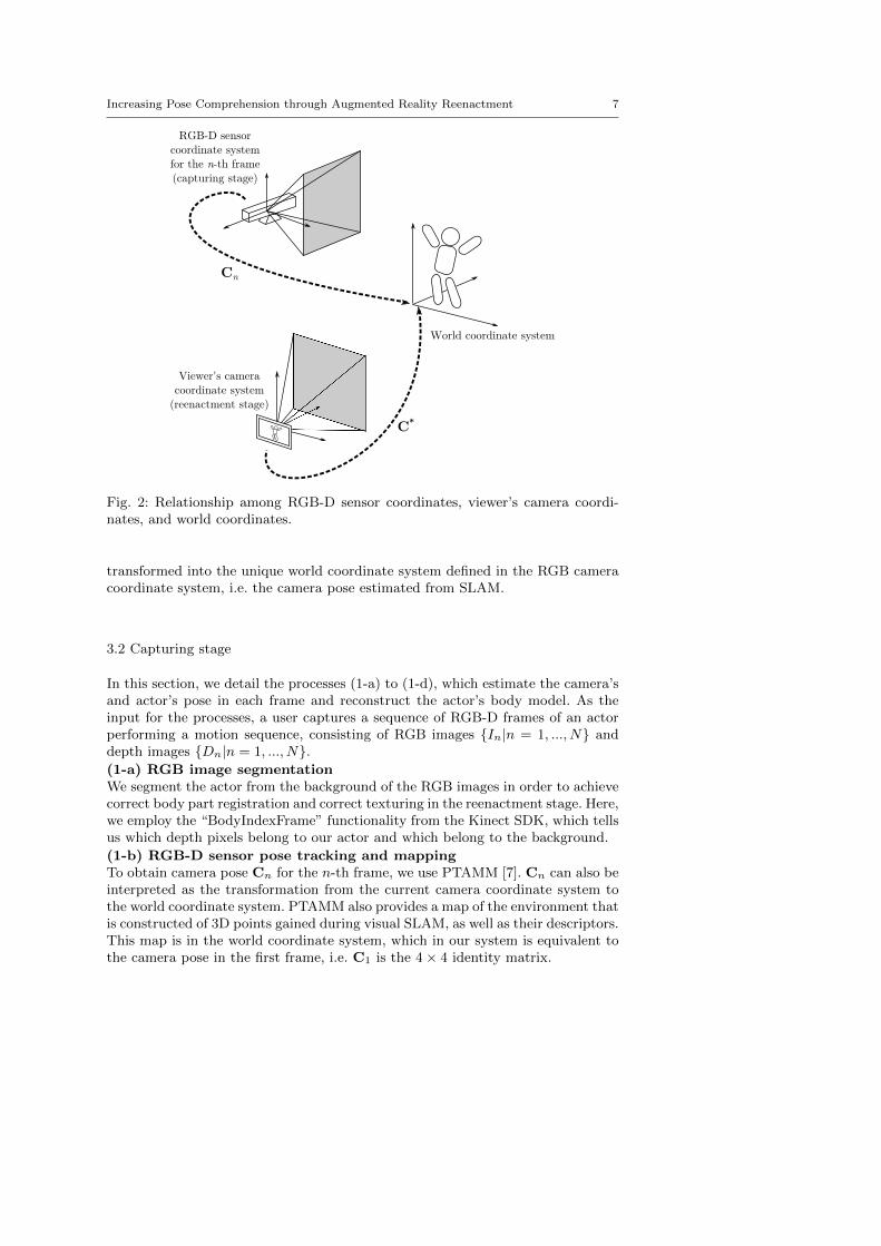
Figure 2 shows the coordinate systems in use. In the system, the world coordinatesystem is defined as a unique base of the coordinate system for both the capturingand reenactment stage, and is set as the camera pose in the first frame in the cap-turing stage. The camera pose is treated as a transform from a sensor coordinatesystem (i.e. RGB-D sensor or viewer’s camera) to the world coordinate system.
Here, it should be noted that in practice, 3D points regained from the depthsensor on the RGB-D sensor and those in the SLAM system’s map are usually indifferent coordinate systems. Additionally, the depth sensor is distinct from theRGB camera, and thus there may be some slight translation or rotation betweenthem. In order to correctly render our reenactment with the model, we must cal-ibrate the transformation parameters, i.e. rotation R, translation t and scale s,among the coordinate systems.
Fortunately, PTAMM [7] tracks a number of map points, which are featurepoints with estimated 3D coordinates in the world coordinate system. We canproject each map point into the depth image to get the corresponding pairs of 3Dpoints, which then gives us the transformation parameters. Given M map points,with pm as the position of the m-th map point relative to the RGB camera and qm
as the corresponding point based on the depth image, we obtain the transformationfrom the skeleton tracker coordinate system to the RGB camera coordinate systemas follows:
(R, t, s) = arg min(R,t,s)
M∑m=1
‖pm − (sRqm + t)‖2. (1)
This least squares problem can be solved by using singular value decomposition.From this point on, all points based on the depth sensor are assumed to have been
Increasing Pose Comprehension through Augmented Reality Reenactment 7
C*
RGB-D sensor
coordinate system
for the n-th frame
(capturing stage)
Viewer's camera
coordinate system
(reenactment stage)
World coordinate system
Cn
Fig. 2: Relationship among RGB-D sensor coordinates, viewer’s camera coordi-nates, and world coordinates.
transformed into the unique world coordinate system defined in the RGB cameracoordinate system, i.e. the camera pose estimated from SLAM.
3.2 Capturing stage
In this section, we detail the processes (1-a) to (1-d), which estimate the camera’sand actor’s pose in each frame and reconstruct the actor’s body model. As theinput for the processes, a user captures a sequence of RGB-D frames of an actorperforming a motion sequence, consisting of RGB images {In|n = 1, ..., N} anddepth images {Dn|n = 1, ..., N}.(1-a) RGB image segmentationWe segment the actor from the background of the RGB images in order to achievecorrect body part registration and correct texturing in the reenactment stage. Here,we employ the “BodyIndexFrame” functionality from the Kinect SDK, which tellsus which depth pixels belong to our actor and which belong to the background.
(1-b) RGB-D sensor pose tracking and mappingTo obtain camera pose Cn for the n-th frame, we use PTAMM [7]. Cn can also beinterpreted as the transformation from the current camera coordinate system tothe world coordinate system. PTAMM also provides a map of the environment thatis constructed of 3D points gained during visual SLAM, as well as their descriptors.This map is in the world coordinate system, which in our system is equivalent tothe camera pose in the first frame, i.e. C1 is the 4× 4 identity matrix.
8 Fabian Lorenzo Dayrit et al.
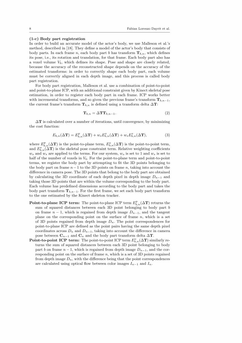
(1-c) Body part registrationIn order to build an accurate model of the actor’s body, we use Malleson et al.’smethod, described in [18]. They define a model of the actor’s body that consists ofbody parts. In each frame n, each body part b has transform Tb,n, which definesits pose, i.e., its rotation and translation, for that frame. Each body part also hasa voxel volume Vb, which defines its shape. Pose and shape are closely related,because the accuracy of the reconstructed shape depends on the accuracy of theestimated transforms: in order to correctly shape each body part, each volumemust be correctly aligned in each depth image, and this process is called bodypart registration.
For body part registration, Malleson et al. use a combination of point-to-pointand point-to-plane ICP, with an additional constraint given by Kinect skeletal poseestimation, in order to register each body part in each frame. ICP works betterwith incremental transforms, and so given the previous frame’s transform Tb,n−1,the current frame’s transform Tb,n is defined using a transform delta ∆T:
Tb,n = ∆TTb,n−1. (2)
∆T is calculated over a number of iterations, until convergence, by minimizingthe cost function:
Eb,n(∆T) = Epb,n(∆T) + woE
ob,n(∆T) + wsE
sb,n(∆T), (3)
where Epb,n(∆T) is the point-to-plane term, Eo
b,n(∆T) is the point-to-point term,and Es
b,n(∆T) is the skeletal pose constraint term. Relative weighting coefficientswo and ws are applied to the terms. For our system, wo is set to 1 and ws is set tohalf of the number of voxels in Vb. For the point-to-plane term and point-to-pointterms, we register the body part by attempting to fit the 3D points belonging tothe body part on frame n−1 to the 3D points on frame n, taking into account thedifference in camera pose. The 3D points that belong to the body part are obtainedby calculating the 3D coordinate of each depth pixel in depth image Dn−1 andtaking those 3D points that are within the volume corresponding to the body part.Each volume has predefined dimensions according to the body part and takes thebody part transform Tb,n−1. For the first frame, we set each body part transformto the one estimated by the Kinect skeleton tracker.
Point-to-plane ICP term: The point-to-plane ICP term Epb,n(∆T) returns the
sum of squared distances between each 3D point belonging to body part bon frame n − 1, which is regained from depth image Dn−1, and the tangentplane on the corresponding point on the surface of frame n, which is a setof 3D points regained from depth image Dn. The point correspondences forpoint-to-plane ICP are defined as the point pairs having the same depth pixelcoordinates across Dn and Dn−1, taking into account the difference in camerapose between Cn−1 and Cn and the body part transform delta ∆T.
Point-to-point ICP term: The point-to-point ICP term Eob,n(∆T) similarly re-
turns the sum of squared distances between each 3D point belonging to bodypart b on frame n− 1, which is regained from depth image Dn−1, and the cor-responding point on the surface of frame n, which is a set of 3D points regainedfrom depth image Dn, with the difference being that the point correspondencesare calculated using optical flow between color images In−1 and In.

Increasing Pose Comprehension through Augmented Reality Reenactment 9
Skeleton constraint term: The skeleton constraint term Esb,n(∆T) returns a
measure of distance between the calculated body part transform Tb,n and theestimated body part transform T∗
b,n acquired from the Kinect skeleton tracker.
In order to be able to solve the cost function linearly the small rotation angleassumption is used to define the transform ∆T as:
∆T = [∆R|∆t] =
1 α −γ tx−α 1 β tyγ −β 1 tz0 0 0 1
. (4)
The derivative of Eb,n(∆T) can then be computed for each component (α, β, γ,tx, ty, tz), obtaining a 6 × 6 symmetric linear system, which is solved as in [15].∆T is composed onto Tb,n after each iteration.(1-d) Body part mesh reconstructionAfter estimating transform Tb,n for body part b in frame n, the correspondingdepth image Dn is then used to reconstruct its 3D shape as a mesh model. Forthis process, we basically follow the method [18], with a slight modification. Here,the 3D shape of each body part is reconstructed as a surface model using the voxel-space signed distance function (SDF) [15] and the marching cubes algorithm [17].Voxel volume Vb has predefined width Wb, height Hb, and depth Db and containsWb×Hb×Db voxels. For each voxel, scores can be calculated indicating the averageobserved signed distance from the surface. Due to such uncertainties as fluctuatingdepth measurements, each depth image’s contribution should be limited. Thus, theSDF is truncated to the range [−µ, µ]. In addition to this, signed distances beneaththe opposite side of the surface will usually be incorrect, as the opposite side isunobserved; therefore, to make the truncated SDF calculation more robust, eachframe’s contribution that are less than −µ is ignored in order to avoid interferingwith any possible surfaces on the other side. More concretely, the score is definedas follows:
F (v) =N∑
n=1
FDn(v)
N∗(v), (5)
FDn(v) =
µ : µ ≤ η(v)η(v) : − µ ≤ η(v) < µ0 : η(v) < −µ
, (6)
where η(v) is the signed distance from the surface to voxel v taking into accountthe transform Tb,n, µ is a predefined constant to truncate the SDF, and N∗(v) isthe number of frames excluding those with η(v) < −µ. In the original method [18],depth pixels are assigned to body part volumes in order to avoid updating thewrong body part; however, we do not do this in our method. The volumes thatwe used had many overlapping regions at the joints, and assigning depth pixels toone body part or the other interfered with the voxel building. Skipping this depthpixel assignment usually results in slightly larger body part models; however, sincewe use view-dependent texturing, the quality of the output does not degrade.
Finding the zero-crossings will thus give an estimate of surface locations. Weapply the marching cubes algorithm [17] in order to convert these voxels into amesh for each body part, as in Fig. 3.

10 Fabian Lorenzo Dayrit et al.
Fig. 3: The generated body part meshes from different angles.
The system stores segmented RGB images {In|n = 1, ..., N}, camera poses{Cn|n = 1, ..., N}, body part transforms {Tb,n|b = 1, ..., B, n = 1, ..., N}, bodypart meshes {Mb|b = 1, ..., B}, and the map in the database.
3.3 Reenactment stage
In the reenactment stage, the viewer captures environment images in real-timeusing a mobile device and the system overlays these images of the real worldwith the reenactment, in the manner of AR. The following details the process forreenacting the pose (i.e., the pose of each body part b, Tb,n) in the n-th frameoverlaid on the real-time image I∗.(2-a) Camera pose trackingIn order to render the reenactment in the place it was captured, we first estimatethe viewer camera pose C∗ for real-time image I∗ captured by the viewer, againusing the visual SLAM technique [7], allowing us to estimate the camera pose inthe world coordinate system which was defined in the capturing stage.
We use the tracked camera pose C∗ in order to transform each body part tothe viewer camera coordinates:
T∗b = C∗C−1
n Tb,n, (7)
where b is the body part id and n is the frame.(2-b) Similar rotation searchWe then apply the appearance of the actor to the transformed body parts by usingview-dependent texture mapping. Most existing techniques for NVS use multipleRGB/RGB-D cameras and sensors in order to reduce invisible regions due toocclusion [32] [6] [1] [25]. Since our system captures from a single RGB-D sensor,it instead uses appropriate RGB images over the course of the entire recording. Wefind appropriate textures for each body part using the similarity of the rotationcomponents of their transforms as a metric. As in Fig. 4, we want to find frame nwith the rotation that is closest to the rotation computed by equation (7):
nb = arg minn
Φ(R∗bR
Tb,n), (8)
where Φ(R) converts rotation matrix R into its axis-angle form and returns theangle, i.e., the magnitude of the rotation.

Increasing Pose Comprehension through Augmented Reality Reenactment 11
Rb,n Rb*Rb
*Rb,nT
Fig. 4: The difference between captured body part rotation Rb,n and virtual ro-tation R∗
b is expressed as another rotation R∗bR
Tb,n.
Fig. 5: Left: checking for occlusions by projecting different body part volumes ontoa texture. Right: unoccluded regions for the chest body part.
(2-c) Applying texturesWe map all x∗, the 3D positions of all visible pixels on the surface of the bodyparts, onto the corresponding transformed mesh as xnb , which are then projectedonto the 2D image in order to get the color at the corresponding pixel of RGBimage Inb .
xnb = Tb,nbT∗−1
b x∗, (9)
x2D = ρ(xnb), (10)
where ρ(x) transforms a point into pixel coordinates by multiplying by the cameramatrix and dividing by the z-coordinate.
Since the actor is reenacted from a viewpoint different from those at which thetextures were originally captured, it should be noted that xnb can be occluded byother body parts as shown in Fig. 5. Background pixels can be detected by referringto the results of actor/background segmentation. In this case, we consider it to bean extraneous part caused by the simplified geometry model, and we show insteadthe corresponding pixel on the real-time image. To handle occlusion, we take thefollowing strategy. First, the system detects the occlusion in Inb for body part b byprojecting each body part in the appropriate pose for the nb-th frame, i.e. Tb,nb
onto the Inb , testing for depth map rendered for all body parts(see Fig. 5). If thebody part is not occluded, the projected body part and the depth map coincide.Otherwise the body part lies farther than the depth map and the system finds thenext-best frame instead of Inb and repeats the process until it finds one in whichthe corresponding pixel is not occluded. The output is shown in Fig. 6.
Finally, we overlay the environment image with the synthesized reenactment,as shown in Fig. 7.

12 Fabian Lorenzo Dayrit et al.
Fig. 6: Textured meshes for the surface model shown in Fig 3.
Fig. 7: Environment image overlayed with reenactment.
4 Experiment
We implemented the proposed reenactment viewing system on a mobile device andevaluated its effect on users’ comprehension of actor’s poses. In this experiment, theeffectiveness of the system is evaluated by checking the pose errors defined betweenthe true pose and the pose recognized by subjects from the system’s output. Wethen confirm the quality and applicability of the proposed reenactment systemcompared to the previously developed system.
4.1 Implementation
We captured motion sequences of performances using a Microsoft Kinect 2. Weimplemented our AR reenactment system on a Microsoft Surface Pro 2 with 4GBRAM and 1.60GHz processor. For skeleton tracking as well as actor-backgroundsegmentation, we relied on the implementation in the Kinect SDK [21]. Our bodymodel contains 15 body parts, seen in Fig. 8. With this configuration, we achievedan interactive FPS ranging from 8 to 12 frames per second during reenactment.
4.2 Evaluation
In order to evaluate the system, we experimentally tested users’ comprehensionof actor’s poses with the reenactment compared with their comprehension with

Increasing Pose Comprehension through Augmented Reality Reenactment 13
Fig. 8: 15 body parts used for body modeling.
conventional 2D images and video using 21 subjects. The experiment consists oftwo parts.Pose angle estimation. In the first part of experiments, users were tasked withestimating the angle of the actor’s arm. The actor was asked to form four differentposes with specific angles between his arm and torso, and we captured these poseswith both our proposed system and a conventional camera, as shown in Fig. 9.Each pose was captured from a different viewing angle, as illustrated in Fig. 10and detailed in Table 1, in order to test the effect of viewing direction on anglecomprehension. In order to aid our system in collecting textures, we also capturedthe actor from different points of view, asking him to hold the pose as still ashe could. For each pose, we showed half of our users the conventional image,and the other half were made to view the pose as an AR reenactment using ourproposed system. Users alternately viewed either the conventional image or theAR reenactment per pose. Specifically, users were divided into Group A and GroupB. Users in Group A were shown Pose (1-1) and (1-3) in conventional images andPose (1-2) and (1-4) using the proposed system, while those in Group B wereshown the opposite.
Users were asked to form the angle using a compass while viewing the pose.We then calculated the mean absolute error (MAE) for all users for the viewers ofthe conventional image and of the proposed system.
Table 1 also shows the results of the experiment. The proposed system’s errorswere generally lower than the conventional result. We can see that as the viewingangle of the conventional image increases, the arm angle estimation error also

14 Fabian Lorenzo Dayrit et al.
(1-1) (1-2) (1-3) (1-4)
Fig. 9: Conventional images depicting the poses which were shown to the usersfor pose angle estimation. In each pose, the actor forms a different angle with hisarm. Each image is also taken from a different viewing angle.
Actor
Actor's front
Camera
Viewing
angle
Arm direction
Fig. 10: Viewing angle shown from the top. A value of 0◦means that the actor isfacing the camera. Arm direction is always perpendicular to the actor’s front.
Table 1: Pose angle estimation results. For the users’ answers, the mean absoluteerrors (MAE) for both the conventional images (conv.) and the proposed system(prop.) were calculated.
Arm angle Viewing angle Conv. MAE Prop. MAE
Pose (1-1) 47◦ 0◦ 7.25◦ 7.62◦
Pose (1-2) 68◦ 26◦ 6.70◦ 9.01◦
Pose (1-3) 95◦ 46◦ 10.48◦ 3.11◦
Pose (1-4) 32◦ 57◦ 10.59◦ 4.90◦

Increasing Pose Comprehension through Augmented Reality Reenactment 15
(1-3)
Fig. 11: Poses (1-1)–(1-4) for pose angle estimation from the front (top row) andside (bottom row), viewed using the AR reenactment system.
16 Fabian Lorenzo Dayrit et al.
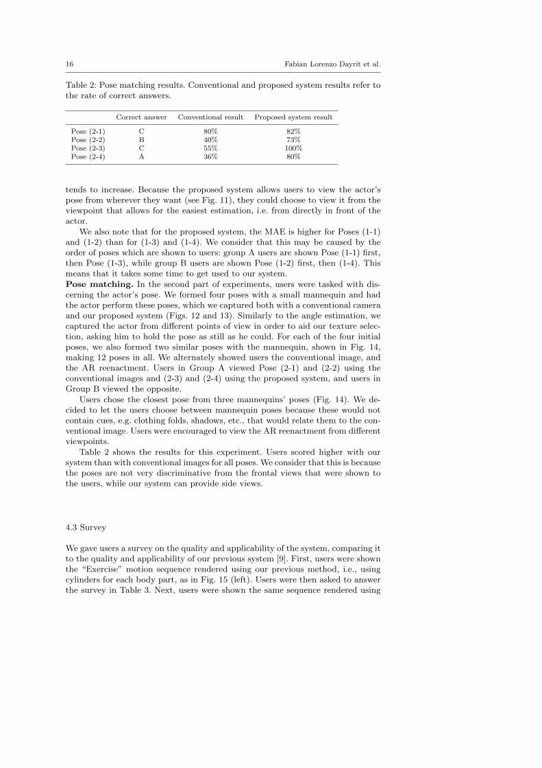
Table 2: Pose matching results. Conventional and proposed system results refer tothe rate of correct answers.
Correct answer Conventional result Proposed system result
Pose (2-1) C 80% 82%Pose (2-2) B 40% 73%Pose (2-3) C 55% 100%Pose (2-4) A 36% 80%
tends to increase. Because the proposed system allows users to view the actor’spose from wherever they want (see Fig. 11), they could choose to view it from theviewpoint that allows for the easiest estimation, i.e. from directly in front of theactor.
We also note that for the proposed system, the MAE is higher for Poses (1-1)and (1-2) than for (1-3) and (1-4). We consider that this may be caused by theorder of poses which are shown to users: group A users are shown Pose (1-1) first,then Pose (1-3), while group B users are shown Pose (1-2) first, then (1-4). Thismeans that it takes some time to get used to our system.Pose matching. In the second part of experiments, users were tasked with dis-cerning the actor’s pose. We formed four poses with a small mannequin and hadthe actor perform these poses, which we captured both with a conventional cameraand our proposed system (Figs. 12 and 13). Similarly to the angle estimation, wecaptured the actor from different points of view in order to aid our texture selec-tion, asking him to hold the pose as still as he could. For each of the four initialposes, we also formed two similar poses with the mannequin, shown in Fig. 14,making 12 poses in all. We alternately showed users the conventional image, andthe AR reenactment. Users in Group A viewed Pose (2-1) and (2-2) using theconventional images and (2-3) and (2-4) using the proposed system, and users inGroup B viewed the opposite.
Users chose the closest pose from three mannequins’ poses (Fig. 14). We de-cided to let the users choose between mannequin poses because these would notcontain cues, e.g. clothing folds, shadows, etc., that would relate them to the con-ventional image. Users were encouraged to view the AR reenactment from differentviewpoints.
Table 2 shows the results for this experiment. Users scored higher with oursystem than with conventional images for all poses. We consider that this is becausethe poses are not very discriminative from the frontal views that were shown tothe users, while our system can provide side views.
4.3 Survey
We gave users a survey on the quality and applicability of the system, comparing itto the quality and applicability of our previous system [9]. First, users were shownthe “Exercise” motion sequence rendered using our previous method, i.e., usingcylinders for each body part, as in Fig. 15 (left). Users were then asked to answerthe survey in Table 3. Next, users were shown the same sequence rendered using

Increasing Pose Comprehension through Augmented Reality Reenactment 17
(2-1) (2-3)(2-2) (2-4)
Fig. 12: Conventional images depicting the four poses that were shown to the usersfor pose matching.
(2-1) (2-3)(2-2) (2-4)
Fig. 13: Poses in Fig. 12 viewed from the side.
(2-1) (2-2)
(2-3) (2-4)
A AB C CB
A B C A B C
Fig. 14: The mannequins to match the poses to. Correct answers are C for 1, Bfor 2, C for 3, and A for 4.
our proposed method, as in Fig. 15 (right)2. Users were then asked to answer thesame questions a second time for the proposed system.
The survey shows that while users were not entirely satisfied with the quality,they were positive toward the reenactment. The answers to Q1 shows that enough
2 A visual comparison of the two rendering methods can be found athttp://yokoya.naist.jp/ fabian-d/arreenactment.htm

18 Fabian Lorenzo Dayrit et al.
Fig. 15: Left: “Exercise” sequence viewed with the previous, cylinder-based system.Right: The same frames viewed with the proposed system.
holes and artifacts exist in the rendering that they disturb the users’ experienceof the previous system. These holes are the result of the rough 3D modeling ofthe target. The output quality has been improved for the proposed system byemploying the state of the art body modeling method [18]. Q2 shows that most ofthe users thought that the motion was smooth enough, with the proposed systemscoring higher. Q3 asks whether the synthesized reenactment looks like the originalvideo. If viewed from the original capture point, it should strongly resemble thevideo since it is using the same video frames as textures. If viewed from elsewhere,however, it must be believable enough to look like it was captured from that

Increasing Pose Comprehension through Augmented Reality Reenactment 19
Table 3: Survey, answers are from 1 (strongly disagree) to 5 (strongly agree).
Question Ave. ([9]) Ave. (proposed)
Q1 I am not bothered by holes and artifacts in the reenactment. 2.62 3.86Q2 The reenactment’s motion is smooth. 3.71 4.29Q3 The reenactment resembles the conventional video. 3.81 4.24
I would prefer to watch the reenactment over the conventional video for...Q4 ...performances. 3.10 3.62Q5 ...training videos. 4.05 4.57Q6 ...sports recordings. 3.52 4.05Q7 ...videos of daily life. 2.43 3.29
viewpoint, and as the answers to Q3 show, most users felt that it accomplishedthis task, with the proposed system’s output being closer to the conventional videodue to having a more accurate body model. Reactions to the listed applicationswere also positive. The highest-scoring application were training videos and sportsrecordings. Users scored our proposed system higher in all aspects compared toour previous system, which shows a marked improvement in quality.
5 Conclusion
In this work, we have developed and implemented a system to capture humanmotion and show its virtualized motion. The process of capturing only requires asingle RGB-D camera, which makes it easier for non-expert users. For showing themotion, the system synthesizes reenactments that can be viewed from arbitraryviewpoints using a mobile device. The reenactments are rendered by reconstructingthe actor’s body parts using 3D mesh models and texturing them using the RGBvideo sequence. The reenactment’s virtual view is based on a map of feature pointsin the environment which we generate using visual SLAM during capturing andreuse in order to render the reenactment relative to its original capturing location.The reenactments are comprehensible by users and generally resemble the videothey were based on. Users of the system are able to more precisely estimate bodyangles at any viewing angle. For cases involving ambiguous poses, the proposedsystem benefits the users by allowing them to view the pose from multiple angles.Its output quality is also higher, compared to our previous system.
For future work, we would like to explore additional applications of the system.Users indicated that they would use the system for watching training videos, andwe agree that the ability to watch a motion from any desired angle would be aboon to learners. Reducing the holes and artifacts in the output until it completelyresembles a conventional video is another possible avenue of research.
Acknowledgements This work was partially supported by JSPS Grant-in-Aid for ScientificResearch Nos. 23240024 and 25540086.
References
1. de Aguiar, E., Stoll, C., Theobalt, C., Ahmed, N., Seidel, H., Thrun, S.: Performancecapture from sparse multi-view video. ACM Trans. on Graphics 27(3) (2008)

20 Fabian Lorenzo Dayrit et al.
2. Alexiadis, D.S., Zarpalas, D., Daras, P.: Real-time, full 3-D reconstruction of movingforeground objects from multiple consumer depth cameras. IEEE Trans. on Multimedia15(2), 339–358 (2013)
3. Anderson, F., Grossman, T., Matejka, J., Fitzmaurice, G.: YouMove: Enhancing movementtraining with an augmented reality mirror. In: Proc. ACM Symposium on User InterfaceSoftware and Technology, pp. 311–320 (2013)
4. Azuma, R.T.: A survey of augmented reality. Presence 6(4), 355–385 (1997)5. Beck, S., Kunert, A., Kulik, A., Froehlich, B.: Immersive group-to-group telepresence.
IEEE Trans. on Visualization and Computer Graphics 19(4), 616–625 (2013)6. Carranza, J., Theobalt, C., Magnor, M., Seidel, H.: Free-viewpoint video of human actors.
ACM Trans. on Graphics 22(3), 569–577 (2003)7. Castle, R., Klein, G., Murray, D.: Video-rate localization in multiple maps for wearable
augmented reality. In: Proc. IEEE Int. Symposium on Wearable Computers, pp. 15–22(2008)
8. Dai, B., Yang, X.: A low-latency 3D teleconferencing system with image based approach.In: Proc. ACM SIGGRAPH Int. Conf. on Virtual-Reality Continuum and Its Applicationsin Industry, pp. 243–248 (2013)
9. Dayrit, F.L., Nakashima, Y., Sato, T., Yokoya, N.: Free-viewpoint AR human-motion reen-actment based on a single RGB-D video stream. In: Proc. IEEE Int. Conf. on Multimediaand Expo, 6 pages. (2014)
10. Debevec, P., Taylor, C., Malik, J.: Modeling and rendering architecture from photographs:A hybrid geometry- and image-based approach. In: Proc. ACM SIGGRAPH, pp. 11–20(1996)
11. Hauswiesner, S., Straka, M., Reitmayr, G.: Image-based clothes transfer. In: Proc. IEEEInt. Symposium on Mixed and Augmented Reality, pp. 169–172 (2011)
12. Henderson, S., Feiner, S.: Augmented reality in the psychomotor phase of a proceduraltask. In: Proc. IEEE Int. Symposium on Mixed and Augmented Reality, pp. 191–200(2011)
13. Hilsmann, A., Fechteler, P., Eisert, P.: Pose space image based rendering. In: Proc. Com-puter Graphics Forum, vol. 32, pp. 265–274 (2013)
14. Hondori, H., Khademi, M., Dodakian, L., Cramer, S., Lopes, C.V.: A spatial augmentedreality rehab system for post-stroke hand rehabilitation. In: Proc. Conf. on Medicine MeetsVirtual Reality, pp. 279–285 (2013)
15. Izadi, S., Kim, D., Hilliges, O., Molyneaux, D., Newcombe, R., Kohli, P., Shotton, J.,Hodges, S., Freeman, D., Davison, A., Fitzgibbon, A.: KinectFusion: Real-time 3D recon-struction and interaction using a moving depth camera. In: Proc. ACM Symposium onUser Interface Software and Technology, pp. 559–568 (2011)
16. Klein, G., Murray, D.: Parallel tracking and mapping for small AR workspaces. In: Proc.IEEE and ACM Int. Symposium on Mixed and Augmented Reality (2007)
17. Lorensen, W., Cline, H.: Marching cubes: A high resolution 3D surface construction algo-rithm. In: Proc. ACM SIGGRAPH, vol. 21, pp. 163–169 (1987)
18. Malleson, C., Klaudiny, M., Hilton, A., Guillemaut, J.Y.: Single-view RGBD-based re-construction of dynamic human geometry. In: Proc. Int. Workshop on Dynamic ShapeCapture and Analysis, pp. 307–314 (2013)
19. Matusik, W., Buehler, C., Raskar, R., Gortler, S., McMillan, L.: Image-based visual hulls.In: Proc. ACM SIGGRAPH, pp. 369–374 (2000)
20. Pages, R., Berjon, D., Moran, F.: Automatic system for virtual human reconstruction with3D mesh multi-texturing and facial enhancement. Signal Processing: Image Communica-tion 28(9), 1089–1099 (2013)
21. Shotton, J., Sharp, T., Kipman, A., Fitzgibbon, A., Finocchio, M., Blake, A., Cook, M.,Moore, R.: Real-time human pose recognition in parts from single depth images. Commu-nications of the ACM 56(1), 116–124 (2013)
22. Shum, H., Kang, S.B.: Review of image-based rendering techniques. Visual Communica-tions and Image Processing pp. 2–13 (2000)
23. Velloso, E., Bulling, A., Gellersen, H.: MotionMA: Motion modelling and analysis bydemonstration. In: Proc. ACM SIGCHI Conf. on Human Factors in Computing Systems,pp. 1309–1318 (2013)
24. Wang, Z., Ong, S., Nee, A.: Augmented reality aided interactive manual assembly design.The International Journal of Advanced Manufacturing Technology 69(5-8), 1311–1321(2013)

Increasing Pose Comprehension through Augmented Reality Reenactment 21
25. Waschbusch, M., Wurmlin, S., Cotting, D., Sadlo, F., Gross, M.: Scalable 3D video ofdynamic scenes. The Visual Computer 21(8-10), 629–638 (2005)
26. Wurmlin, S., Lamboray, E., Staadt, O., Gross, M.: 3D video recorder. In: Proc. PacificConf. on Computer Graphics and Applications, pp. 325–334 (2002)
27. Xu, F., Liu, Y., Stoll, C., Tompkin, J., Bharaj, G., Dai, Q., Seidel, H.P., Kautz, J.,Theobalt, C.: Video-based characters: creating new human performances from a multi-view video database. ACM Trans. on Graphics 30(4), 10 pages. (2011)
28. Yamabe, T., Nakajima, T.: Playful training with augmented reality games: case studiestowards reality-oriented system design. Multimedia Tools and Applications 62(1), 259–286(2013)
29. Ye, G., Liu, Y., Deng, Y., Hasler, N., Ji, X., Dai, Q., Theobalt, C.: Free-viewpoint videoof human actors using multiple handheld Kinects. IEEE Trans. on Cybernetics 43(5),1370–1382 (2013)
30. Zhang, Z.: A flexible new technique for camera calibration. IEEE Trans. on PatternAnalysis and Machine Intelligence 22(11), 1330–1334 (2000)
31. Zhou, Z., Shu, B., Zhuo, S., Deng, X., Tan, P., Lin, S.: Image-based clothes animation forvirtual fitting. In: Proc. ACM SIGGRAPH Asia, 4 pages. (2012)
32. Zitnick, C., Kang, S., Uyttendaele, M., Winder, S., Szeliski, R.: High-quality video viewinterpolation using a layered representation. ACM Trans. on Graphics 23(3), 600–608(2004)