Incorporation of graphene into SnO2 photoanodes for … University Institutional Repository...
30
•
Transcript of Incorporation of graphene into SnO2 photoanodes for … University Institutional Repository...
Loughborough UniversityInstitutional Repository
Incorporation of grapheneinto SnO2 photoanodes fordye-sensitized solar cells
This item was submitted to Loughborough University's Institutional Repositoryby the/an author.
Citation: BATMUNKH, M. ...et al., 2016. Incorporation of graphene intoSnO2 photoanodes for dye-sensitized solar cells. Applied Surface Science, 387,pp. 690-697.
Additional Information:
• This paper was accepted for publication in the journal Applied Sur-face Science and the definitive published version is available athttp://dx.doi.org/10.1016/j.apsusc.2016.06.146
Metadata Record: https://dspace.lboro.ac.uk/2134/22263
Version: Accepted for publication
Publisher: c© Elsevier
Rights: This work is made available according to the conditions of the Cre-ative Commons Attribution-NonCommercial-NoDerivatives 4.0 International(CC BY-NC-ND 4.0) licence. Full details of this licence are available at:https://creativecommons.org/licenses/by-nc-nd/4.0/
Please cite the published version.
Incorporation of graphene into SnO2 photoanode for dye-sensitized solar cells
Munkhbayar Batmunkh a,b,1, Mahnaz Dadkhah b,1, Cameron J. Shearer b, Mark J. Biggs a,c,
Joseph G. Shapter b,*
a School of Chemical Engineering, The University of Adelaide, Adelaide, South Australia
5005, Australia b Centre for Nanoscale Science and Technology, School of Chemical and Physical Sciences,
Flinders University, Bedford Park, Adelaide, South Australia 5042, Australia c School of Science, Loughborough University, Loughborough, Leicestershire, LE11 3TU,
UK
Corresponding author: Joseph G. Shapter,
E-mail: [email protected]; Tel: (+61) 08 82012005
1 These authors contributed equally
Abstract
In dye-sensitized solar cell (DSSC) photoanodes, tin dioxide (SnO2) structures are promising
alternative semiconducting oxide to the conventional titania (TiO2), but they suffer from poor
photovoltaic (PV) efficiency caused by insufficient dye adsorption and low energy value of
the conduction band. A hybrid structure consisting of SnO2 and reduced graphene oxide
(SnO2–RGO) was synthesized via a microwave-assisted method and has been employed as a
photoanode in DSSCs. Incorporation of RGO into the SnO2 photoanode enhanced the power
conversion efficiency of DSSC device by 91.5%, as compared to the device assembled
without RGO. This efficiency improvement can be attributed to increased dye loading,
enhanced electron transfer and addition of suitable energy levels in of the photoanode.
Finally, the use of RGO addresses the major shortcoming of SnO2 when employed as a DSSC
photoanode, namely poor dye adsorption and slow electron transfer rate.
Keywords
Photovoltaic, dye-sensitized solar cells, photoanodes, tin dioxide, graphene
1. Introduction
One of the mature developments in new energy production approaches is the dye-sensitized
solar cell (DSSC) [1].For a broad perspective of the field, there are several good reviews
available [2-4]. A typical DSSC photoanode is made using a transparent conducting oxide
(TCO) substrate, wide band gap oxide semiconductor and dye sensitizer. A nanocrystalline
TiO2 semiconductor is mostly used as the semiconductor due to its unique properties [5].
Despite the high power conversion efficiencies (PCEs) achieved by devices fabricated with
TiO2 photoanodes [6-8], the intrinsic low carrier mobility of TiO2 is a matter of great concern
[9, 10]. This issue has led many researchers to probe the development of alternative
photoanode materials.
Among many alternative semiconductors, SnO2 has been the subject of numerous
investigations [11-13]. This is partially due to the fact that SnO2 has a higher electron
mobility than TiO2 [14, 15]. Since the first use of SnO2 in DSSCs, significant developments
have been made in the SnO2 photoanodes [11, 13]. These developments include morphology
control, doping with various species, surface modification, and hybrid structures with other
oxide semiconductors [16-18]. Despite the considerable effort to improve SnO2 based
photoanodes, a major challenge for SnO2 based DSSCs is still their low performance caused
by poor dye adsorption capability [19]. Additionally, the SnO2 photoanode based DSSCs
suffer from a low open circuit voltage (Voc) value due to the intrinsically low energy of the
conduction band of SnO2 [20]. Therefore, addressing these issues is of great importance for
the development of SnO2 based photovoltaic (PV) cells. Moreover, although SnO2 possesses
higher electron mobility than TiO2, further improvement in the electron transport in SnO2
photoanode would be of great value to maximize the efficiency.
Due to their excellent conductivity, carbon nanotubes (CNTs) and graphene can act to
improve electron transport and reduce the charge recombination which results from sluggish
charge transport of semiconducting oxide based photoanodes; thus significantly enhancing
the PCE of PV cells [21-26]. Over the past few years, researchers have incorporated graphene
derivatives into various TiO2 structures and shown remarkable efficiency enhancement [27-
30]. However, until now, there has been no report on the use of graphene structures in SnO2
photoanodes for DSSCs. Moreover, the kinetics of dye adsorption and performance
enhancement for carbonaceous photoanodes is still unclear, with some studies suggesting
contrary results [21, 28, 29, 31, 32]. Therefore, exploring the effect of graphene or reduced
graphene oxide (RGO) in SnO2 photoanode based DSSCs would be valuable.
Herein we report a facile preparation of hybrid structures based on morphologically
controllable SnO2 combined with RGO for use as a photoanode in DSSCs. To the best of our
knowledge, this work is the first effort involving the application of a graphene structure in
SnO2 photoanode based DSSCs. We found that the incorporation of RGO into the SnO2 film
not only enhances the electron transfer rate of the photoanode, it also increases the adsorption
of dye molecules into the film, thus greatly improving DSSC performance.
2. Experimental
2.1.Materials
All chemicals were purchased from Sigma-Aldrich and used without further purification,
unless otherwise stated. Tin (II) chloride dihydrate (SnCl2·2H2O) powder (>99% purity,
Merck) was used as a starting material. Flourine-doped tin oxide (FTO) coated glass
electrode with a sheet resistance (Rs) of ~12 Ω/□ (TCO30-8), Ruthenizer 535-bisTBA (N719
dye), iodide/tri-iodide electrolyte (Iodolyte Z-50), DuPont Surlyn® (Meltonix 1170-60) and
Platinum catalyst (Platisol T) were obtained from Solaronix, Switzerland.
2.2.Preparation of graphene oxide
Graphite oxide was prepared from natural graphite using the approach from Marcano et al.
[33]. Briefly, a 9:1 (v:v) mixture of sulfuric acid (95-98% H2SO4) and phosphoric acid (85%
H3PO4) (240:27 mL) was kept in the cold room (3-5oC) until it was added to a mixture of
graphite flakes (2 g) and potassium permanganate (99% KMnO4) (12 g). The oxidation
process of graphite was carried out by stirring the mixture at ~50oC for 12 h. Upon
completion, the reaction was cooled down to room temperature and poured onto ice
(approximately 300 mL) with 30% hydrogen peroxide (H2O2) (2 mL). The mixture was then
washed with distilled (DI) water, 30% hydrochloric acid (HCl) and ethanol (x 2 times). For
each sequential wash, the product was centrifuged at 4400 rpm for 3 h and the supernatant
decanted away. The obtained light brown sample was then vacuum-dried overnight at room
temperature. Then the as-prepared graphite oxide was exfoliated in water (1 mg mL-1-) by
bath ultrasonication (Elma, Germany) for 60 min to obtain homogenous graphene oxide (GO)
dispersion.
2.3.Synthesis of SnO2-RGO hybrid
The SnO2-RGO hybrid was prepared using a facile microwave-assisted method [34]. In a
typical process, six glass beakers containing 90 mL DI water and different GO content (0 mg,

2 mg, 4.5 mg, 7 mg, 12 mg and 50 mg) were ultrasonicated for 2h. Meanwhile, 1.5 g of
SnCl2·2H2O powder was added into 200 mL of 0.02M HCl solution. Then the previously
prepared GO dispersions were added into the SnCl2·2H2O solutions, followed by stirring for
30 min. The as-obtained mixtures were then reacted using a microwave technique
(StartSYNTH Microwave Synthesis Labstation, Milestone s.r.l) for 5 min under 600 W
power. The temperature was adjusted to 90oC during the microwave treatment. After cooling
to room temperature, the obtained precipitates were centrifuged at 2000 rpm for 10 min and
washed several times with DI water, followed by drying overnight at 80oC in an oven to
obtain SnO2-RGO powders. Finally, six samples of different RGO content (0 wt%, 0.2 wt%,
0.45 wt%, 0.7 wt%, 1.2 wt% and 4.75 wt% in the hybrid) were prepared and have been used
for DSSC fabrication. It should be noted that the amount of SnO2 in these samples was not
changed. For the calculation of the RGO concentration in the hybrid, it was assumed that the
conversion of SnCl2·2H2O to SnO2 is 100% based on the lack of Cl peak observed in various
hybrid characterizations.
2.4.Device fabrication
Firstly, viscous SnO2 and SnO2-RGO pastes were prepared from the previously prepared six
samples according to the established procedures described in the literature [35]. FTO coated
glass substrates were cleaned by a detergent (Pyroneg), followed by washing with Milli-Q
water, acetone and ethanol under ultrasonication for 10 min each and subsequently dried with
a nitrogen gas. The cleaned FTO glass subtrates were immersed in a 40 mM TiCl4 aqueous
solution at 70oC for 30 min. Then the TiCl4 treated FTO electrodes were coated with the
SnO2 and SnO2-RGO pastes by a doctor blade technique to prepare the photoanodes. All
photoanode films were obtained by applying two layers of adhesive scotch tape (Magic™
Tape, 3M) on the FTO electrode, which gives a film thickness of ~15 µm [36]. It is well
established that the photoanode thickness of 12-16 µm is the optimum condition for
achieving high DSSC performance [36-38]. After the deposition of SnO2 and SnO2-RGO
pastes onto the FTO substrates, the photoanode films were gradually heated under an air flow
at 125oC for 5 min, 325oC for 5 min, at 375oC for 15 min and at 450oC for 30 min, followed
by cooling to room temperature. Then the films were again soaked in 40 mM TiCl4 solution
at 70oC for 30 min, followed by sintering at 450oC for 30 min. After cooling to ~50oC, the
prepared films were immersed into 0.5 mM N719 dye in an ethanol solution for 20 h at 40oC.
Then, the dye adsorbed photoanodes were washed with ethanol to remove non-adsorbed dye
from the films.
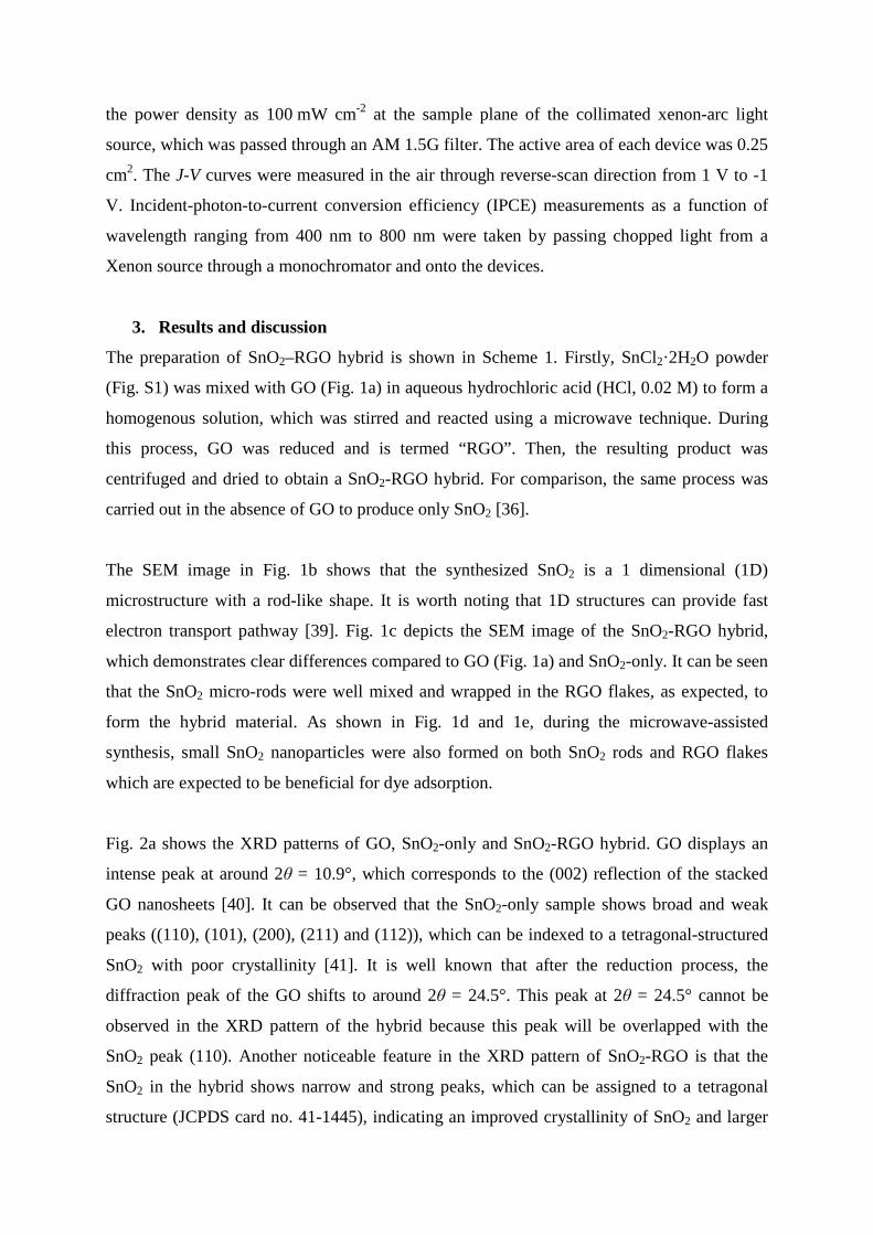
In the meantime, platinum (Pt) catalyst was coated onto FTO substrates from Pt precursor
(Solaronix) by a brush-painting method to prepare the counter electrodes. The dye-adsorbed
photoanodes and Pt counter electrodes were assembled into a sealed sandwich-type cell, with
a 60 µm thick hot-melt sealing Surlyn between each layer. The electrolyte solution, Iodolyte
Z-50 (Solaronix), was introduced into the cell via a vacuum-filling method through an
injection hole on the counter electrode side. Finally, the hole was sealed with scotch tape.
2.5.Characterization
Scanning electron microscopy (SEM) images were obtained using an Inspect F50 SEM (FEI)
with accelerating voltage of 10 kV. Energy dispersive X-ray spectroscopy (EDX) analysis
was completed on the same system with Team EDS Octane Pro (EDAX) attachment.
Elemental compositions of the samples were analyzed at binding energy ranging from 0 eV to
1200 eV using a X-ray photoelectron spectroscopy (XPS), Leybold Heraeus LHS-10 with a
SPECS XR-50 dual anode source operating at 250W. The Mg-Kα source, which has energy
of 1253.6 eV, was used for the XPS analysis. X-ray diffraction (XRD) patterns were carried
out on a powder X-ray diffractometer at 40 kV and 15 mA in the range of 2θ = 3–80° using
Cu Kα radiation (Model Miniflex 600, Rigaku, Japan). Attenuated Total Reflection-Fourier
Transform Infrared Spectroscopy (ATR-FTIR) spectra were acquired over a wavenumber
range of 4000-500 cm–1 in transmission mode using a Frontier FTIR spectrometer (Perkin
Elmer, USA) with a germanium crystal. Raman spectroscopy was carried out on LabRAM
HR Evolution spectrometer (Horiba Jobin Yvon, Japan). Raman spectra were collected using
a 532 nm laser (mpc 3000) as the excitation source. A 50x objective was used with a confocal
hole size of 100 μm. Auger spectromicroscopy “PHI 710 scanning auger nanoprobe”
operating at base vacuum below 1x10⁻⁹ Torr was used to analyse the elemental analysis of
the samples. Sputtering samples for the analysis was performed using ultra high purity
Argon. Data was collected using an electron beam of 10 kV, 10nA.
To determine the adsorbed amount of dye molecules in the SnO2 and SnO2-RGO films, the
dye in the films was dissolved in 0.1 M NaOH aqueous solution and then measured by a
Varian Cary 50G UV-vis Spectrophotometer at wavelengths ranging from 300 to 1000 nm.
Sheet resistivities were performed on the microscope slide substrate coated with SnO2-only
and/or SnO2-RGO hybrid using a four point probe technique (KeithLink Technology Co.,
Ltd. Taiwan). The photocurrent–voltage (J–V) characteristics were investigated using a
Keithley 2400 SMU instrument and recorded using a custom LabView Virtual Instrument
program. A standard silicon test cell with NIST-traceable certification was used to calibrate
the power density as 100 mW cm-2 at the sample plane of the collimated xenon-arc light
source, which was passed through an AM 1.5G filter. The active area of each device was 0.25
cm2. The J-V curves were measured in the air through reverse-scan direction from 1 V to -1
V. Incident-photon-to-current conversion efficiency (IPCE) measurements as a function of
wavelength ranging from 400 nm to 800 nm were taken by passing chopped light from a
Xenon source through a monochromator and onto the devices.
3. Results and discussion
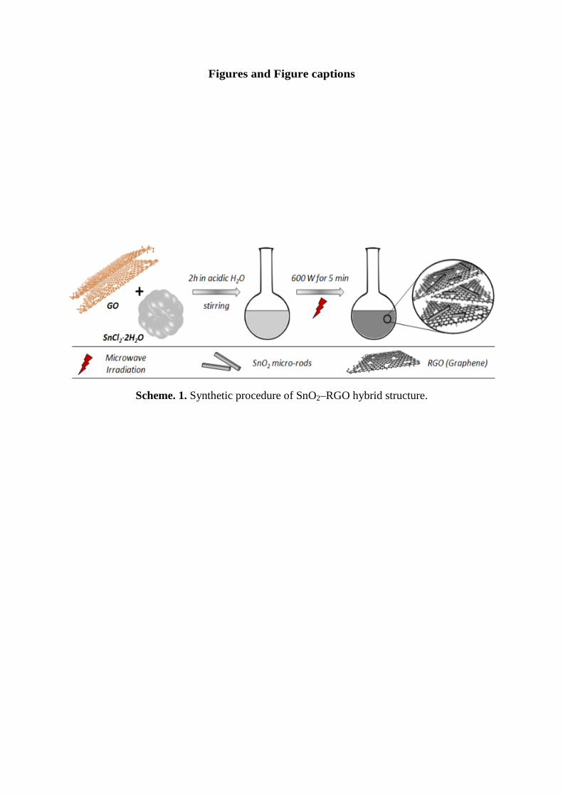
The preparation of SnO2–RGO hybrid is shown in Scheme 1. Firstly, SnCl2·2H2O powder
(Fig. S1) was mixed with GO (Fig. 1a) in aqueous hydrochloric acid (HCl, 0.02 M) to form a
homogenous solution, which was stirred and reacted using a microwave technique. During
this process, GO was reduced and is termed “RGO”. Then, the resulting product was
centrifuged and dried to obtain a SnO2-RGO hybrid. For comparison, the same process was
carried out in the absence of GO to produce only SnO2 [36].
The SEM image in Fig. 1b shows that the synthesized SnO2 is a 1 dimensional (1D)
microstructure with a rod-like shape. It is worth noting that 1D structures can provide fast
electron transport pathway [39]. Fig. 1c depicts the SEM image of the SnO2-RGO hybrid,
which demonstrates clear differences compared to GO (Fig. 1a) and SnO2-only. It can be seen
that the SnO2 micro-rods were well mixed and wrapped in the RGO flakes, as expected, to
form the hybrid material. As shown in Fig. 1d and 1e, during the microwave-assisted
synthesis, small SnO2 nanoparticles were also formed on both SnO2 rods and RGO flakes
which are expected to be beneficial for dye adsorption.
Fig. 2a shows the XRD patterns of GO, SnO2-only and SnO2-RGO hybrid. GO displays an
intense peak at around 2θ = 10.9°, which corresponds to the (002) reflection of the stacked
GO nanosheets [40]. It can be observed that the SnO2-only sample shows broad and weak
peaks ((110), (101), (200), (211) and (112)), which can be indexed to a tetragonal-structured
SnO2 with poor crystallinity [41]. It is well known that after the reduction process, the
diffraction peak of the GO shifts to around 2θ = 24.5°. This peak at 2θ = 24.5° cannot be
observed in the XRD pattern of the hybrid because this peak will be overlapped with the
SnO2 peak (110). Another noticeable feature in the XRD pattern of SnO2-RGO is that the
SnO2 in the hybrid shows narrow and strong peaks, which can be assigned to a tetragonal
structure (JCPDS card no. 41-1445), indicating an improved crystallinity of SnO2 and larger
average crystal size [42]. This improvement in the crystallinity is often observed in
nanocarbon-metal oxide materials and is attributed to a heat-sink effect in which the
nanocarbon facilitates crystallization via heat transfer [43].
The results of the XRD analysis were further confirmed by characterizing the samples using
XPS (Fig. 2b), ATR-FTIR (Fig. 3a) and Raman spectroscopy (Fig. 3b). It can be clearly
observed from the Raman spectra of the SnO2-RGO hybrid (Fig. 3b) that the ID/IG ratio of
RGO increased compared to that of the GO. This increase in the ID/IG ratio can be attributed
to the defects caused during reduction of GO [27]. Moreover, it should be noted that in the
XPS survey spectra, negligible peaks (Cl 2p) can be found in the SnO2-based samples, which
could be attributed to the unreacted Cl– of SnCl2·2H2O. Additionally, Auger and EDX
elemental analysis were carried out on selected area of SEM images of the SnO2-RGO hybrid
and reveal small amount of chlorine remaining in the sample (see Fig. S2). These results of
Auger and EDX spectroscopies were in good agreement with the XPS and may explain the
sample crystallinity.
To study the influence of RGO on the efficiency of PV cells, DSSCs were fabricated using
six photoanodes of different RGO content in the hybrid and were evaluated using simulated
AM1.5 sunlight with an output power of 100 mW cm-2. Notably, for the fabrication of
DSSCs, the photoanodes were immersed in a TiCl4 aqueous solution before they were soaked
in the dye solution. This process is a commonly followed strategy to deposit a thin layer of
TiO2 over SnO2 (SnO2-RGO in our case) which can improve the Voc of the SnO2-based
DSSCs [18, 44-46]. Therefore, the photoanodes were denoted as “TiO2-SnO2-RGO (X)”,
where the value of X indicates the weight concentration (wt%) of RGO in the hybrid. For
example, the photoanode film prepared with 0.2 wt% RGO is denoted “TiO2-SnO2-RGO
(0.2)”.
The photocurrent density–voltage (J–V) characteristics of the DSSCs assembled with these
photoanodes are shown in Fig. 4a and the corresponding PV parameters have been
summarized in Table 1. The control DSSC device (TiO2-SnO2-RGO (0)) fabricated based on
SnO2 photoanode without RGO showed an average PCE (η) of 1.28 ± 0.52% with a short–
circuit current (Jsc) value of 4.78 ± 0.95 mA cm–2 and Voc of 0.64 ± 0.01V which are typical
values for such cells [12, 18].
It can be seen from Table 1 that from TiO2-SnO2-RGO (0) to TiO2-SnO2-RGO (0.7)
(increasing RGO content), the Jsc value increases from 4.78 ± 0.95 to 10.23 ± 0.88 mA cm–2.
We hypothesize that this increase in the Jsc is due to the improved dye loading into the film
and enhanced electron transfer within the photoanode [22, 27, 28]. In order to confirm our
hypothesis, we fabricated SnO2 films (Fig. S3) with different RGO content and investigated
the dye adsorption capability of the films. No treatment with TiCl4 solution was done to allow
the effect of RGO in the SnO2 film on the extent of dye adsorption to be probed without any
interference. As shown in Fig. S3, the films after dye adsorption and also the solutions after
subsequent desorption of the dye molecules using NaOH show that the dye adsorption of the
SnO2 films was significantly improved by incorporating RGO. Moreover, UV-vis spectra in
Fig. 4b show the absorbance of dye desorbed from the films and shows that dye adsorption
increases with increasing RGO concentration in the hybrid. This improvement in the dye
adsorption is most likely due to a better matching of the molecular nature of the N719 dye
and the chemical nature of the hybrid. N719 has both polar groups and aromatic regions.
Since our RGO was derived from GO, some functional groups (–OH, –COOH etc.) would
remain on the surface of RGO due to the partial reduction and these would interact with the
polar groups on N719. These functional groups may be playing an important role in the dye
adsorption [21]. SnO2 would also interact with these polar groups. The introduction of the
RGO provides some aromatic nature to the hybrid and one can speculate that this will create
polar and aromatic regions in close proximity and will further enhance dye adsorption.
Additionally the high-surface area of RGO may contribute to the adsorption of the dye [28].
Interestingly, the dye adsorption of the film with the highest RGO content (4.75 wt%) is
starting to saturate, indicating that adding more RGO into the film would likely not lead to
significant further increases in dye adsorption (see Fig. S4).
To determine the mechanism for the improved Jsc value, the resistivity (Rs) of the TiCl4
treated SnO2 film without and with 0.45 wt% RGO was measured using a four point probe.
The same film thickness on a glass substrate was obtained using the doctor blade method (see
experimental details). The film without RGO shows a Rs of 4.51 x 10⁶ Ω/□, while the RGO
incorporated film exhibits a comparatively low Rs (1.81 x 10⁶ Ω/□) (see Table S1). The
decrease in the Rs (nearly 3-fold) of the film with RGO is due to the fact that high
conductivity of the RGO in the hybrid reduces the interfacial resistance between SnO2. In
addition, the measured series resistance (Rseries) of the TiO2-SnO2-RGO (0.45) based DSSC
was 97.9 Ω, which was ~1.7-fold lower than that of the control cell (Table S1). On the basis
of these results, it is clear that the presence of RGO accelerated electron transport process
within the photoanode and suppressed the charge recombination of the cells; thus
significantly enhancing the η [21, 22, 28].
However, although TiO2-SnO2-RGO (0.7) based cell showed the highest Jsc (10.95 mA cm–2),
the measured average η (2.08 ± 0.17%) was not the best observed, despite the films having
high dye adsorption. When the RGO concentration in the hybrid further increased to 1.2 wt%
and 4.75 wt%, a significant drop in the Jsc value and Voc was observed for the TiO2-SnO2-
RGO (1.2) and TiO2-SnO2-RGO (4.75) based DSSCs, thus resulting in very poor efficiencies.
We attribute this η decrease of the DSSCs with higher RGO loading to (i) opacity of the film
(see films before dye adsorption in Fig. S3) reducing light absorption and (ii) high catalytic
property of RGO, which has been shown to limit the continuous electron transfer at the
photoanode [2, 21, 47].
It is well established that although carbon materials can facilitate electron transport in the
DSSC, the catalytic activity of carbon materials toward reduction of the electrolyte causes
significant charge recombination at the interface of the photoanode and electrolyte (since this
reaction should only occur at the cathode) if too high concentration of carbon is used [2]. Fig.
4c shows the dark J–V characteristics of DSSCs fabricated without and with RGO in the
SnO2 photoanodes. It is known that the magnitude and onset of the dark current indicates the
level of charge recombination between the electrons from the dye excitation process and the
I3− ions in the electrolyte [48]. It can be seen that the dark current onset shifted to a lower
potential after adding a small amount of RGO into the SnO2 photoanodes. This is known to
be due to the increased charge recombination rate of the DSSCs caused by the reaction
between the RGO and electrolyte. Therefore, at a given voltage, the dark current increased
when the RGO was added into the SnO2 photoanode of DSSC. Our finding is in line with
similar report of adding carbon powders into TiO2 photoanodes [48].
Indeed, the highest η (3.16%) with an average η of 2.94 ± 0.24% was achieved for the device
based on TiO2-SnO2-RGO (0.45). In the TiO2-SnO2-RGO based DSSC, the TiO2 can act as a
barrier layer reducing the contact of RGO with the electrolyte and therefore reducing the
likelihood of RGO catalyzing recombination at the photoanode. Taking into account the TiO2
deposition process (dip coating) which unlikely to achieve 100 % coverage, we speculate that
with higher RGO content the net amount of RGO in contact with the electrolyte will increase
accordingly. Moreover, we fabricated SnO2 and SnO2-RGO photoanodes based DSSCs
without TiCl4 treatment and their PV results have been plotted in Fig. S5a. The efficiencies of
these DSSCs were ~2-fold lower than those of the devices fabricated with TiCl4 treatment,
confirming that the use of TiCl4 treatment is a vital method to enhance the cell performance
in SnO2 photoanode DSSCs.
It can be seen from Table 1 that all parameters of DSSC fabricated with SnO2 photoanodes
increased after incorporating 0.45 wt% RGO. The calculated η enhancement of TiO2-SnO2-
RGO (0.45) photoanode based device was impressive (91.5%) as compared to the control cell
especially in light of the fact that a very small amount of RGO is required to realise these
large improvements in efficiency. This photoanode (TiO2-SnO2-RGO (0.45)) was chosen for
further investigation to fully understand the role of RGO in the DSSC.
IPCE spectra offer important information on the light harvesting efficiency which is mainly
determined by the absorption of light by the dye molecules at the photoanode and electron
transport processes. The IPCE spectra of the DSSCs with and without RGO in the
photoanode are illustrated in Fig. 4d. It should be noted that the IPCE spectra of the DSSCs
were characterized after the devices were aged for approximately 10 days. The IPCE of the
TiO2-SnO2-RGO (0.45) photoanode based device is higher than that of the control DSSC
over the entire wavelength region. The lack of wavelength dependence indicates that the
addition of RGO into the SnO2 photoanode improves the DSSC performance without altering
the internal mechanism, likely by enhancing electron transfer rate and increasing dye
adsorption onto the photoanode.
As discussed earlier, RGO in the hybrid ensures rapid electron transport process (Fig. 5a) and
significantly enhances the Jsc value of the DSSC. Importantly, it can be expected that
incorporation of RGO in the SnO2 photoanode would improve the DSSC performance owing
to presence of suitable energy levels. Fig. 5b shows an energy level diagram for the TiCl4
treated SnO2 photoanode with RGO. Since a thin TiO2 layer was deposited on the FTO and
on the SnO2 or SnO2-RGO layers by TiCl4 treatment, it is reasonable to include the energy
level of TiO2 in this diagram. The red arrow in Fig. 5b represents the fact that the electron
transfer from the conduction band of SnO2 to that of TiO2 is not possible due to their
mismatching band energy levels. As the TiO2 coverage on the FTO is incomplete (not 100%),
both SnO2 and TiO2 are in contact with the FTO and hence electron transfer from both the
SnO2 and TiO2 to the FTO is still feasible. The results from Fig. S6 and S7 show that despite
the fact that the TiO2 on the FTO is very thin, it does make a contribution to the current and
voltage of the cell and as such is important to show. Since the energy level of RGO (-4.40
eV) lies between the conduction band of TiO2 (-4.26 eV) and SnO2 (-4.56 eV), the electrons
can be rapidly transferred stepwise from the TiO2 to the SnO2 conduction band (see Fig. 5b)
[18, 28].Here RGO can act as a bridge between TiO2 and SnO2. This effective electron
transfer would likely reduce the charge recombination of the cell, thus improves the
performance.
Finally, the PV parameters of our best-performing cells have been compared with values
reported in the literature for other DSSCs with SnO2 based photoanodes. Table 2 summarizes
the PV parameters such as Jsc, Voc, FF and η of DSSC devices fabricated with various SnO2
structures based photoanodes and our best performing cells. It can be observed from Table 2
that the efficiency observed for our DSSC fabricated with SnO2-RGO photoanode is
comparable or higher than those achieved by other 1D and 3D SnO2 structured photoanode
films. Therefore, this indicates that the incorporation of graphene structures into SnO2
photoanode is an effective strategy to achieve high efficiency DSSCs.
4. Conclusion
In summary, the successful application of RGO structures in 1D SnO2 micro-rod based
photoanodes for DSSCs has been demonstrated. Herein we show that the application of RGO
overcomes the major shortcoming of SnO2 when applied as a DSSC photoanode, namely
poor dye adsorption. In addition, owing to its suitable energy levels and excellent
conductivity, RGO significantly improved the electron transport rate in the cells. Importantly,
PCE (η) of the DSSC was significantly improved to 3.16% by incorporating a very small
amount of RGO into the photoanode, demonstrating a ~91.5% enhancement in the efficiency
when compared to SnO2-only photoanode based DSSC (1.65%).
Acknowledgements
The support of the Australian Research Council Discovery Program (DP130101714) is
gratefully acknowledged. Munkhbayar Batmunkh acknowledges International
Postgraduate Research Scholarship (IPRS) and Australian Postgraduate Award (APA)
for their financial support during his study in Australia. We acknowledge the use of
South Australian node of the Australian Microscopy & Microanalysis Research
Facility (AMMRF) at Flinders University.
Appendix A. Supplementary data
Supplementary data associated with this article can be found, in the online version.
References
[1] G. Hashmi, K. Miettunen, T. Peltola, J. Halme, I. Asghar, K. Aitola, M. Toivola, P. Lund, Review of materials and manufacturing options for large area flexible dye solar cells, Renewable and Sustainable Energy Reviews, 15 (2011) 3717-3732. [2] M. Batmunkh, M.J. Biggs, J.G. Shapter, Carbon Nanotubes for Dye-Sensitized Solar Cells, Small, 11 (2015) 2963-2989. [3] F. Bella, C. Gerbaldi, C. Barolo, M. Gratzel, Aqueous dye-sensitized solar cells, Chemical Society Reviews, 44 (2015) 3431-3473. [4] J. Wu, Z. Lan, J. Lin, M. Huang, Y. Huang, L. Fan, G. Luo, Electrolytes in Dye-Sensitized Solar Cells, Chemical Reviews, 115 (2015) 2136-2173. [5] Y. Hao, E. Gabrielsson, P.W. Lohse, W. Yang, E.M.J. Johansson, A. Hagfeldt, L. Sun, G. Boschloo, Peripheral Hole Acceptor Moieties on an Organic Dye Improve Dye-Sensitized Solar Cell Performance, Advanced Science, 2 (2015) 1500174. [6] L. Han, A. Islam, H. Chen, C. Malapaka, B. Chiranjeevi, S. Zhang, X. Yang, M. Yanagida, High-efficiency dye-sensitized solar cell with a novel co-adsorbent, Energy & Environmental Science, 5 (2012) 6057-6060. [7] S. Mathew, A. Yella, P. Gao, R. Humphry-Baker, F.E. CurchodBasile, N. Ashari-Astani, I. Tavernelli, U. Rothlisberger, K. NazeeruddinMd, M. Grätzel, Dye-sensitized solar cells with 13% efficiency achieved through the molecular engineering of porphyrin sensitizers, Nat Chem, 6 (2014) 242-247. [8] S.G. Hashmi, M. Ozkan, J. Halme, K.D. Misic, S.M. Zakeeruddin, J. Paltakari, M. Grätzel, P.D. Lund, High performance dye-sensitized solar cells with inkjet printed ionic liquid electrolyte, Nano Energy, 17 (2015) 206-215. [9] A.K. Chandiran, M. Abdi-Jalebi, M.K. Nazeeruddin, M. Grätzel, Analysis of Electron Transfer Properties of ZnO and TiO2 Photoanodes for Dye-Sensitized Solar Cells, ACS Nano, 8 (2014) 2261-2268. [10] J. Fan, Z. Li, W. Zhou, Y. Miao, Y. Zhang, J. Hu, G. Shao, Dye-sensitized solar cells based on TiO2 nanoparticles/nanobelts double-layered film with improved photovoltaic performance, Applied Surface Science, 319 (2014) 75-82. [11] S. Ferrere, A. Zaban, B.A. Gregg, Dye Sensitization of Nanocrystalline Tin Oxide by Perylene Derivatives, The Journal of Physical Chemistry B, 101 (1997) 4490-4493. [12] Q. Wali, A. Fakharuddin, I. Ahmed, M.H. Ab Rahim, J. Ismail, R. Jose, Multiporous nanofibers of SnO2 by electrospinning for high efficiency dye-sensitized solar cells, Journal of Materials Chemistry A, 2 (2014) 17427-17434. [13] Q. Wali, A. Fakharuddin, R. Jose, Tin oxide as a photoanode for dye-sensitised solar cells: Current progress and future challenges, Journal of Power Sources, 293 (2015) 1039-1052. [14] I. Concina, A. Vomiero, Metal Oxide Semiconductors for Dye- and Quantum-Dot-Sensitized Solar Cells, Small, 11 (2015) 1744-1774. [15] E. Ramasamy, J. Lee, Ordered Mesoporous SnO2−Based Photoanodes for High-Performance Dye-Sensitized Solar Cells, The Journal of Physical Chemistry C, 114 (2010) 22032-22037. [16] S. Gubbala, V. Chakrapani, V. Kumar, M.K. Sunkara, Band-Edge Engineered Hybrid Structures for Dye-Sensitized Solar Cells Based on SnO2 Nanowires, Advanced Functional Materials, 18 (2008) 2411-2418.
[17] J. Gong, H. Qiao, S. Sigdel, H. Elbohy, N. Adhikari, Z. Zhou, K. Sumathy, Q. Wei, Q. Qiao, Characteristics of SnO2 nanofiber/TiO2 nanoparticle composite for dye-sensitized solar cells, AIP Advances, 5 (2015) 067134. [18] A. Thapa, J. Zai, H. Elbohy, P. Poudel, N. Adhikari, X. Qian, Q. Qiao, TiO2 coated urchin-like SnO2 microspheres for efficient dye-sensitized solar cells, Nano Research, 7 (2014) 1154-1163. [19] C.-L. Wang, J.-Y. Liao, Y. Zhao, A. Manthiram, Template-free TiO2 hollow submicrospheres embedded with SnO2 nanobeans as a versatile scattering layer for dye-sensitized solar cells, Chemical Communications, 51 (2015) 2848-2850. [20] A. Birkel, Y.-G. Lee, D. Koll, X.V. Meerbeek, S. Frank, M.J. Choi, Y.S. Kang, K. Char, W. Tremel, Highly efficient and stable dye-sensitized solar cells based on SnO2 nanocrystals prepared by microwave-assisted synthesis, Energy & Environmental Science, 5 (2012) 5392-5400. [21] M. Batmunkh, M.J. Biggs, J.G. Shapter, Carbonaceous Dye-Sensitized Solar Cell Photoelectrodes, Advanced Science, 2 (2015) 1400025. [22] J.D. Roy-Mayhew, I.A. Aksay, Graphene Materials and Their Use in Dye-Sensitized Solar Cells, Chemical Reviews, 114 (2014) 6323-6348. [23] M. Batmunkh, C.J. Shearer, M.J. Biggs, J.G. Shapter, Nanocarbons for mesoscopic perovskite solar cells, Journal of Materials Chemistry A, 3 (2015) 9020-9031. [24] A. Kongkanand, R. Martínez Domínguez, P.V. Kamat, Single Wall Carbon Nanotube Scaffolds for Photoelectrochemical Solar Cells. Capture and Transport of Photogenerated Electrons, Nano Letters, 7 (2007) 676-680. [25] S.-B. Kim, J.-Y. Park, C.-S. Kim, K. Okuyama, S.-E. Lee, H.-D. Jang, T.-O. Kim, Effects of Graphene in Dye-Sensitized Solar Cells Based on Nitrogen-Doped TiO2 Composite, The Journal of Physical Chemistry C, 119 (2015) 16552-16559. [26] A. Sacco, S. Porro, A. Lamberti, M. Gerosa, M. Castellino, A. Chiodoni, S. Bianco, Investigation of Transport and Recombination Properties in Graphene/Titanium Dioxide Nanocomposite for Dye-Sensitized Solar Cell Photoanodes, Electrochimica Acta, 131 (2014) 154-159. [27] Z. He, G. Guai, J. Liu, C. Guo, J.S. Chye Loo, C.M. Li, T.T.Y. Tan, Nanostructure control of graphene-composited TiO2 by a one-step solvothermal approach for high performance dye-sensitized solar cells, Nanoscale, 3 (2011) 4613-4616. [28] Y.-B. Tang, C.-S. Lee, J. Xu, Z.-T. Liu, Z.-H. Chen, Z. He, Y.-L. Cao, G. Yuan, H. Song, L. Chen, L. Luo, H.-M. Cheng, W.-J. Zhang, I. Bello, S.-T. Lee, Incorporation of Graphenes in Nanostructured TiO2 Films via Molecular Grafting for Dye-Sensitized Solar Cell Application, ACS Nano, 4 (2010) 3482-3488. [29] T. Chen, W. Hu, J. Song, G.H. Guai, C.M. Li, Interface Functionalization of Photoelectrodes with Graphene for High Performance Dye-Sensitized Solar Cells, Advanced Functional Materials, 22 (2012) 5245-5250. [30] Y.H. Ng, I.V. Lightcap, K. Goodwin, M. Matsumura, P.V. Kamat, To What Extent Do Graphene Scaffolds Improve the Photovoltaic and Photocatalytic Response of TiO2 Nanostructured Films?, The Journal of Physical Chemistry Letters, 1 (2010) 2222-2227. [31] P. Brown, K. Takechi, P.V. Kamat, Single-Walled Carbon Nanotube Scaffolds for Dye-Sensitized Solar Cells, The Journal of Physical Chemistry C, 112 (2008) 4776-4782. [32] K.T. Dembele, G.S. Selopal, C. Soldano, R. Nechache, J.C. Rimada, I. Concina, G. Sberveglieri, F. Rosei, A. Vomiero, Hybrid Carbon Nanotubes–TiO2 Photoanodes for High Efficiency Dye-Sensitized Solar Cells, The Journal of Physical Chemistry C, 117 (2013) 14510-14517. [33] D.C. Marcano, D.V. Kosynkin, J.M. Berlin, A. Sinitskii, Z. Sun, A. Slesarev, L.B. Alemany, W. Lu, J.M. Tour, Improved Synthesis of Graphene Oxide, ACS Nano, 4 (2010) 4806-4814. [34] L. Yin, D. Chen, X. Cui, L. Ge, J. Yang, L. Yu, B. Zhang, R. Zhang, G. Shao, Normal-pressure microwave rapid synthesis of hierarchical SnO2@rGO nanostructures with superhigh surface areas as high-quality gas-sensing and electrochemical active materials, Nanoscale, 6 (2014) 13690-13700. [35] Y. Xiong, D. He, Y. Jin, P.J. Cameron, K.J. Edler, Ordered Mesoporous Particles in Titania Films with Hierarchical Structure as Scattering Layers in Dye-Sensitized Solar Cells, The Journal of Physical Chemistry C, 119 (2015) 22552-22559.
[36] M. Batmunkh, M. Dadkhah, C.J. Shearer, M.J. Biggs, J.G. Shapter, Tin oxide light scattering layer for titania photoanodes in dye-sensitized solar cells, Energy Technology, 4 (2016) DOI: 10.1002/ente.201600008. [37] L. Yang, W.W.-F. Leung, Electrospun TiO2 Nanorods with Carbon Nanotubes for Efficient Electron Collection in Dye-Sensitized Solar Cells, Advanced Materials, 25 (2013) 1792-1795. [38] S. Ito, T.N. Murakami, P. Comte, P. Liska, C. Grätzel, M.K. Nazeeruddin, M. Grätzel, Fabrication of thin film dye sensitized solar cells with solar to electric power conversion efficiency over 10%, Thin Solid Films, 516 (2008) 4613-4619. [39] P. Poudel, Q. Qiao, One dimensional nanostructure/nanoparticle composites as photoanodes for dye-sensitized solar cells, Nanoscale, 4 (2012) 2826-2838. [40] Y.-T. Xu, Y. Guo, H. Jiang, X.-B. Xie, B. Zhao, P.-L. Zhu, X.-Z. Fu, R. Sun, C.-P. Wong, Enhanced Performance of Lithium-Ion Batteries with Copper Oxide Microspheres @ Graphene Oxide Micro/Nanocomposite Electrodes, Energy Technology, 3 (2015) 488-495. [41] M. Dadkhah, M. Salavati-Niasari, Controlled synthesis of tin dioxide nanostructures via two simple methods and the influence on dye sensitized solar cell, Electrochimica Acta, 129 (2014) 62-68. [42] A.L. Patterson, The Scherrer Formula for X-Ray Particle Size Determination, Physical Review, 56 (1939) 978-982. [43] Z. Ren, E. Kim, S.W. Pattinson, K.S. Subrahmanyam, C.N.R. Rao, A.K. Cheetham, D. Eder, Hybridizing photoactive zeolites with graphene: a powerful strategy towards superior photocatalytic properties, Chemical Science, 3 (2012) 209-216. [44] J. Qian, P. Liu, Y. Xiao, Y. Jiang, Y. Cao, X. Ai, H. Yang, TiO2-Coated Multilayered SnO2 Hollow Microspheres for Dye-Sensitized Solar Cells, Advanced Materials, 21 (2009) 3663-3667. [45] M.-S. Wu, Z.-Z. Ceng, C.-Y. Chen, Surface modification of porous TiO2 electrode through pulse oxidative hydrolysis of TiCl3 as an efficient light harvesting photoanode for dye-sensitized solar cells, Electrochimica Acta, 191 (2016) 256-262. [46] Q. Yi, S. Cong, H. Wang, Y. Wang, X. Dai, J. Zhao, Y. Sun, Y. Lou, G. Zou, High-stability Ti4+ precursor for the TiO2 compact layer of dye-sensitized solar cells, Applied Surface Science, 356 (2015) 587-592. [47] J. Chen, B. Li, J. Zheng, J. Zhao, Z. Zhu, Role of Carbon Nanotubes in Dye-Sensitized TiO2-Based Solar Cells, The Journal of Physical Chemistry C, 116 (2012) 14848-14856. [48] S.H. Kang, J.-Y. Kim, Y.-K. Kim, Y.-E. Sung, Effects of the incorporation of carbon powder into nanostructured TiO2 film for dye-sensitized solar cell, Journal of Photochemistry and Photobiology A: Chemistry, 186 (2007) 234-241. [49] M.-H. Kim, Y.-U. Kwon, Semiconducting Divalent Metal Oxides as Blocking Layer Material for SnO2-Based Dye-Sensitized Solar Cells, The Journal of Physical Chemistry C, 115 (2011) 23120-23125. [50] Y. Duan, J. Zheng, N. Fu, Y. Fang, T. Liu, Q. Zhang, X. Zhou, Y. Lin, F. Pan, Enhancing the performance of dye-sensitized solar cells: doping SnO2 photoanodes with Al to simultaneously improve conduction band and electron lifetime, Journal of Materials Chemistry A, 3 (2015) 3066-3073. [51] C. Gao, X. Li, X. Zhu, L. Chen, Z. Zhang, Y. Wang, Z. Zhang, H. Duan, E. Xie, Branched hierarchical photoanode of titanium dioxide nanoneedles on tin dioxide nanofiber network for high performance dye-sensitized solar cells, Journal of Power Sources, 264 (2014) 15-21. [52] E.N. Kumar, R. Jose, P.S. Archana, C. Vijila, M.M. Yusoff, S. Ramakrishna, High performance dye-sensitized solar cells with record open circuit voltage using tin oxide nanoflowers developed by electrospinning, Energy & Environmental Science, 5 (2012) 5401-5407. [53] T. Krishnamoorthy, M.Z. Tang, A. Verma, A.S. Nair, D. Pliszka, S.G. Mhaisalkar, S. Ramakrishna, A facile route to vertically aligned electrospun SnO2 nanowires on a transparent conducting oxide substrate for dye-sensitized solar cells, Journal of Materials Chemistry, 22 (2012) 2166-2172. [54] J.T. Park, C.S. Lee, J.H. Kim, One-pot synthesis of hierarchical mesoporous SnO2 spheres using a graft copolymer: enhanced photovoltaic and photocatalytic performance, RSC Advances, 4 (2014) 31452-31461.
Figures and Figure captions
Scheme. 1. Synthetic procedure of SnO2–RGO hybrid structure.
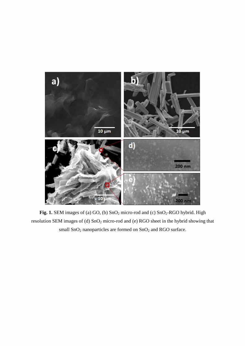
Fig. 1. SEM images of (a) GO, (b) SnO2 micro-rod and (c) SnO2-RGO hybrid. High
resolution SEM images of (d) SnO2 micro-rod and (e) RGO sheet in the hybrid showing that
small SnO2 nanoparticles are formed on SnO2 and RGO surface.
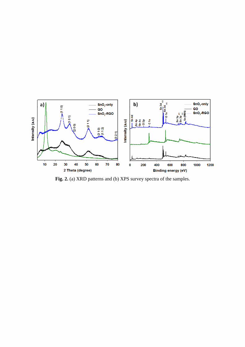
Fig. 2. (a) XRD patterns and (b) XPS survey spectra of the samples.
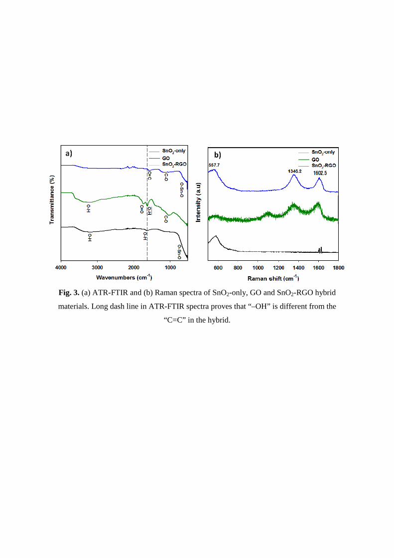
Fig. 3. (a) ATR-FTIR and (b) Raman spectra of SnO2-only, GO and SnO2-RGO hybrid
materials. Long dash line in ATR-FTIR spectra proves that “–OH” is different from the
“C=C” in the hybrid.
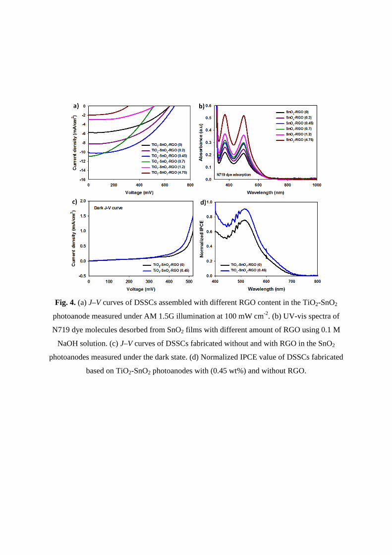
Fig. 4. (a) J–V curves of DSSCs assembled with different RGO content in the TiO2-SnO2
photoanode measured under AM 1.5G illumination at 100 mW cm-2. (b) UV-vis spectra of
N719 dye molecules desorbed from SnO2 films with different amount of RGO using 0.1 M
NaOH solution. (c) J–V curves of DSSCs fabricated without and with RGO in the SnO2
photoanodes measured under the dark state. (d) Normalized IPCE value of DSSCs fabricated
based on TiO2-SnO2 photoanodes with (0.45 wt%) and without RGO.
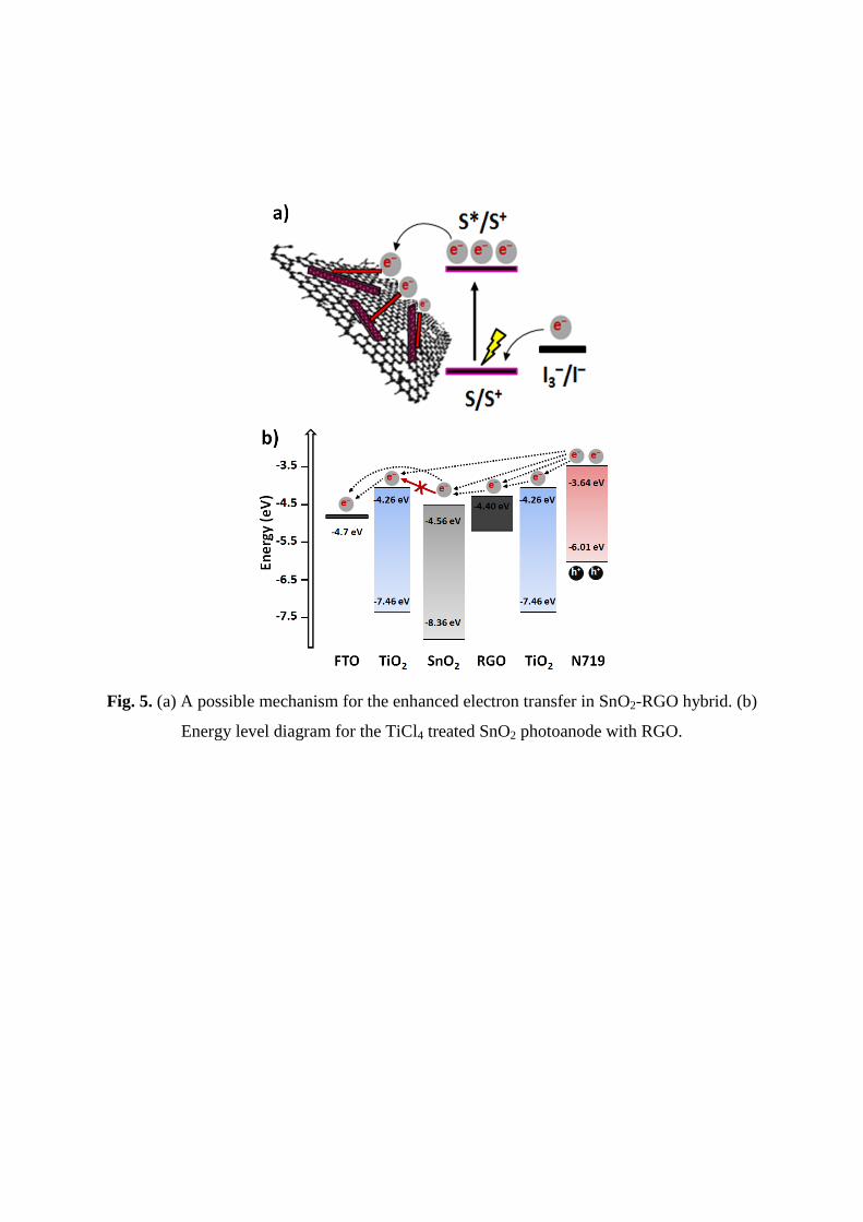
Fig. 5. (a) A possible mechanism for the enhanced electron transfer in SnO2-RGO hybrid. (b)
Energy level diagram for the TiCl4 treated SnO2 photoanode with RGO.
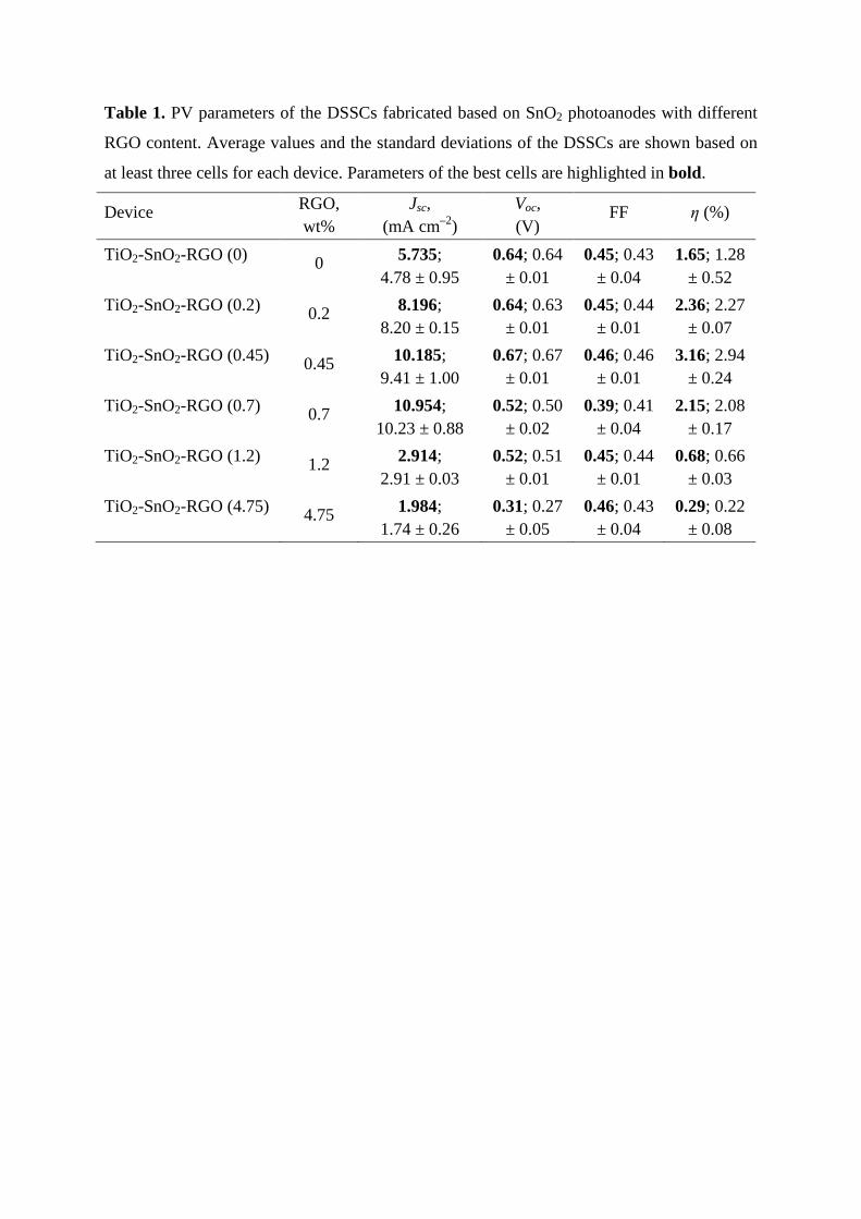
Table 1. PV parameters of the DSSCs fabricated based on SnO2 photoanodes with different
RGO content. Average values and the standard deviations of the DSSCs are shown based on
at least three cells for each device. Parameters of the best cells are highlighted in bold.
Device RGO, wt%
Jsc, (mA cm–2)
Voc, (V)
FF η (%)
TiO2-SnO2-RGO (0) 0 5.735; 4.78 ± 0.95
0.64; 0.64 ± 0.01
0.45; 0.43 ± 0.04
1.65; 1.28 ± 0.52
TiO2-SnO2-RGO (0.2) 0.2 8.196; 8.20 ± 0.15
0.64; 0.63 ± 0.01
0.45; 0.44 ± 0.01
2.36; 2.27 ± 0.07
TiO2-SnO2-RGO (0.45) 0.45 10.185; 9.41 ± 1.00
0.67; 0.67 ± 0.01
0.46; 0.46 ± 0.01
3.16; 2.94 ± 0.24
TiO2-SnO2-RGO (0.7) 0.7 10.954; 10.23 ± 0.88
0.52; 0.50 ± 0.02
0.39; 0.41 ± 0.04
2.15; 2.08 ± 0.17
TiO2-SnO2-RGO (1.2) 1.2 2.914; 2.91 ± 0.03
0.52; 0.51 ± 0.01
0.45; 0.44 ± 0.01
0.68; 0.66 ± 0.03
TiO2-SnO2-RGO (4.75) 4.75 1.984; 1.74 ± 0.26
0.31; 0.27 ± 0.05
0.46; 0.43 ± 0.04
0.29; 0.22 ± 0.08
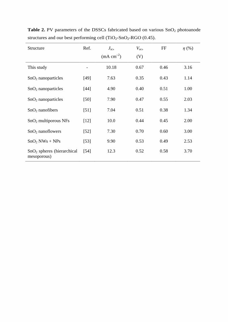
Table 2. PV parameters of the DSSCs fabricated based on various SnO2 photoanode
structures and our best performing cell (TiO2-SnO2-RGO (0.45).
Structure Ref. Jsc,
(mA cm–2)
Voc,
(V)
FF η (%)
This study - 10.18 0.67 0.46 3.16
SnO2 nanoparticles [49] 7.63 0.35 0.43 1.14
SnO2 nanoparticles [44] 4.90 0.40 0.51 1.00
SnO2 nanoparticles [50] 7.90 0.47 0.55 2.03
SnO2 nanofibers [51] 7.04 0.51 0.38 1.34
SnO2 multiporous NFs [12] 10.0 0.44 0.45 2.00
SnO2 nanoflowers [52] 7.30 0.70 0.60 3.00
SnO2 NWs + NPs [53] 9.90 0.53 0.49 2.53
SnO2 spheres (hierarchical mesoporous)
[54] 12.3 0.52 0.58 3.70
Supplementary Information
Incorporation of Graphene into SnO2 Photoanode for Dye-
Sensitized Solar Cells
Munkhbayar Batmunkh,a,b,1 Mahnaz Dadkhah,b,1 Cameron J. Shearer,b Mark J. Biggs,a,c
and Joseph G. Shapter b,*
a School of Chemical Engineering, The University of Adelaide, Adelaide, South Australia
5005, Australia
b School of Chemical and Physical Sciences, Flinders University, Bedford Park,
Adelaide, South Australia 5001, Australia
c School of Science, Loughborough University, Loughborough, Leicestershire, LE11
3TU, UK
1 These authors contributed equally
Corresponding Author:
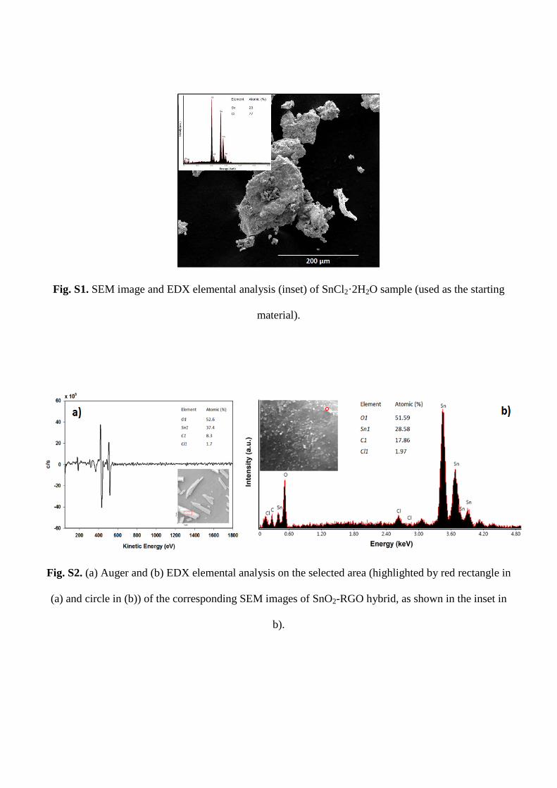
Fig. S1. SEM image and EDX elemental analysis (inset) of SnCl2·2H2O sample (used as the starting
material).
Fig. S2. (a) Auger and (b) EDX elemental analysis on the selected area (highlighted by red rectangle in
(a) and circle in (b)) of the corresponding SEM images of SnO2-RGO hybrid, as shown in the inset in
b).
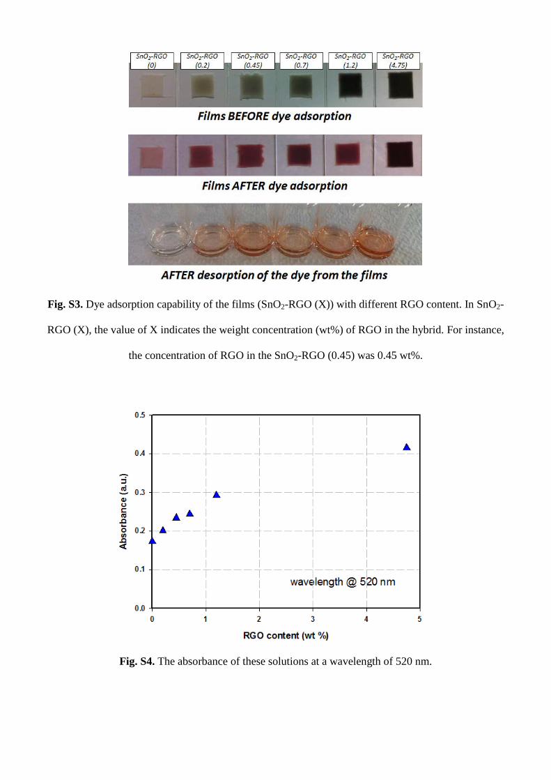
Fig. S3. Dye adsorption capability of the films (SnO2-RGO (X)) with different RGO content. In SnO2-
RGO (X), the value of X indicates the weight concentration (wt%) of RGO in the hybrid. For instance,
the concentration of RGO in the SnO2-RGO (0.45) was 0.45 wt%.
Fig. S4. The absorbance of these solutions at a wavelength of 520 nm.
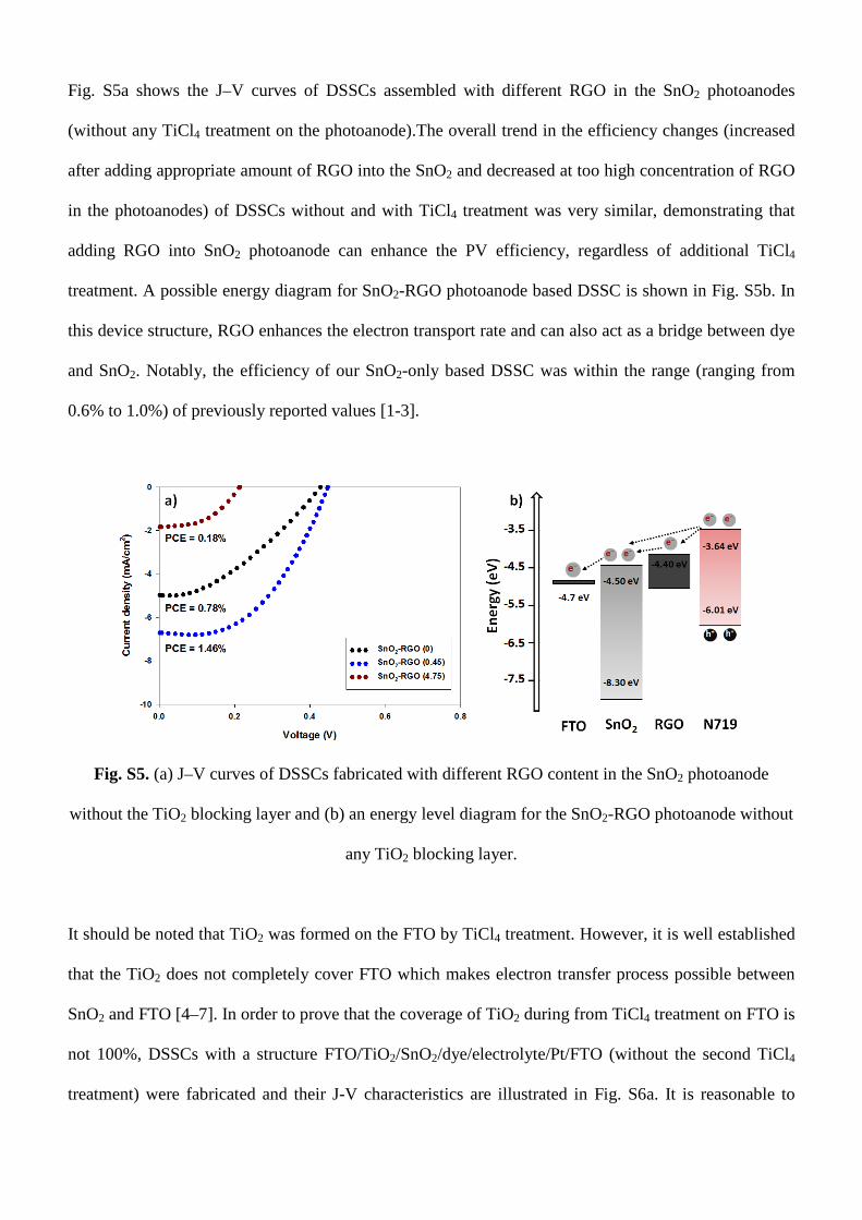
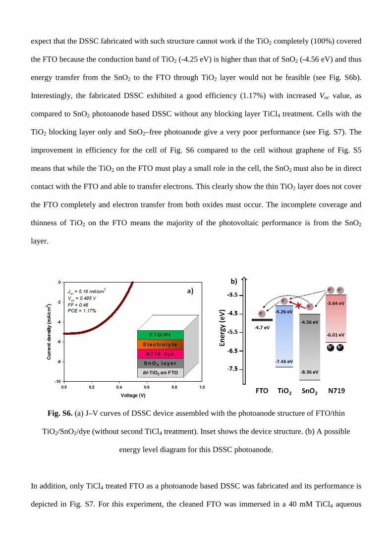
Fig. S5a shows the J–V curves of DSSCs assembled with different RGO in the SnO2 photoanodes
(without any TiCl4 treatment on the photoanode).The overall trend in the efficiency changes (increased
after adding appropriate amount of RGO into the SnO2 and decreased at too high concentration of RGO
in the photoanodes) of DSSCs without and with TiCl4 treatment was very similar, demonstrating that
adding RGO into SnO2 photoanode can enhance the PV efficiency, regardless of additional TiCl4
treatment. A possible energy diagram for SnO2-RGO photoanode based DSSC is shown in Fig. S5b. In
this device structure, RGO enhances the electron transport rate and can also act as a bridge between dye
and SnO2. Notably, the efficiency of our SnO2-only based DSSC was within the range (ranging from
0.6% to 1.0%) of previously reported values [1-3].
Fig. S5. (a) J–V curves of DSSCs fabricated with different RGO content in the SnO2 photoanode
without the TiO2 blocking layer and (b) an energy level diagram for the SnO2-RGO photoanode without
any TiO2 blocking layer.
It should be noted that TiO2 was formed on the FTO by TiCl4 treatment. However, it is well established
that the TiO2 does not completely cover FTO which makes electron transfer process possible between
SnO2 and FTO [4–7]. In order to prove that the coverage of TiO2 during from TiCl4 treatment on FTO is
not 100%, DSSCs with a structure FTO/TiO2/SnO2/dye/electrolyte/Pt/FTO (without the second TiCl4
treatment) were fabricated and their J-V characteristics are illustrated in Fig. S6a. It is reasonable to
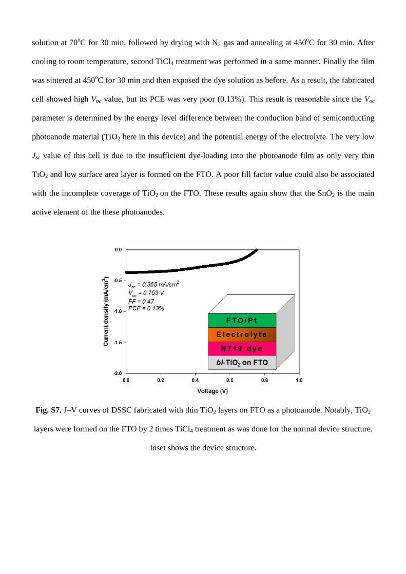
expect that the DSSC fabricated with such structure cannot work if the TiO2 completely (100%) covered
the FTO because the conduction band of TiO2 (-4.25 eV) is higher than that of SnO2 (-4.56 eV) and thus
energy transfer from the SnO2 to the FTO through TiO2 layer would not be feasible (see Fig. S6b).
Interestingly, the fabricated DSSC exhibited a good efficiency (1.17%) with increased Voc value, as
compared to SnO2 photoanode based DSSC without any blocking layer TiCl4 treatment. Cells with the
TiO2 blocking layer only and SnO2–free photoanode give a very poor performance (see Fig. S7). The
improvement in efficiency for the cell of Fig. S6 compared to the cell without graphene of Fig. S5
means that while the TiO2 on the FTO must play a small role in the cell, the SnO2 must also be in direct
contact with the FTO and able to transfer electrons. This clearly show the thin TiO2 layer does not cover
the FTO completely and electron transfer from both oxides must occur. The incomplete coverage and
thinness of TiO2 on the FTO means the majority of the photovoltaic performance is from the SnO2
layer.
Fig. S6. (a) J–V curves of DSSC device assembled with the photoanode structure of FTO/thin
TiO2/SnO2/dye (without second TiCl4 treatment). Inset shows the device structure. (b) A possible
energy level diagram for this DSSC photoanode.
In addition, only TiCl4 treated FTO as a photoanode based DSSC was fabricated and its performance is
depicted in Fig. S7. For this experiment, the cleaned FTO was immersed in a 40 mM TiCl4 aqueous
solution at 70oC for 30 min, followed by drying with N2 gas and annealing at 450oC for 30 min. After
cooling to room temperature, second TiCl4 treatment was performed in a same manner. Finally the film
was sintered at 450oC for 30 min and then exposed the dye solution as before. As a result, the fabricated
cell showed high Voc value, but its PCE was very poor (0.13%). This result is reasonable since the Voc
parameter is determined by the energy level difference between the conduction band of semiconducting
photoanode material (TiO2 here in this device) and the potential energy of the electrolyte. The very low
Jsc value of this cell is due to the insufficient dye-loading into the photoanode film as only very thin
TiO2 and low surface area layer is formed on the FTO. A poor fill factor value could also be associated
with the incomplete coverage of TiO2 on the FTO. These results again show that the SnO2 is the main
active element of the these photoanodes.
Fig. S7. J–V curves of DSSC fabricated with thin TiO2 layers on FTO as a photoanode. Notably, TiO2
layers were formed on the FTO by 2 times TiCl4 treatment as was done for the normal device structure.
Inset shows the device structure.
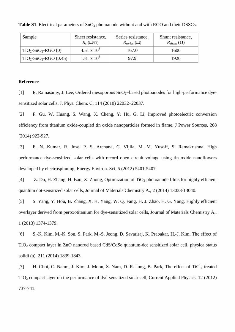
Table S1. Electrical parameters of SnO2 photoanode without and with RGO and their DSSCs.
Sample Sheet resistance, Rs (Ω/□)
Series resistance, Rseries (Ω)
Shunt resistance, Rshunt (Ω)
TiO2-SnO2-RGO (0) 4.51 x 10⁶ 167.0 1600
TiO2-SnO2-RGO (0.45) 1.81 x 10⁶ 97.9 1920
Reference
[1] E. Ramasamy, J. Lee, Ordered mesoporous SnO2−based photoanodes for high-performance dye-
sensitized solar cells, J. Phys. Chem. C, 114 (2010) 22032–22037.
[2] F. Gu, W. Huang, S. Wang, X. Cheng, Y. Hu, G. Li, Improved photoelectric conversion
efficiency from titanium oxide-coupled tin oxide nanoparticles formed in flame, J Power Sources, 268
(2014) 922-927.
[3] E. N. Kumar, R. Jose, P. S. Archana, C. Vijila, M. M. Yusoff, S. Ramakrishna, High
performance dye-sensitized solar cells with record open circuit voltage using tin oxide nanoflowers
developed by electrospinning, Energy Environ. Sci, 5 (2012) 5401-5407.
[4] Z. Du, H. Zhang, H. Bao, X. Zhong, Optimization of TiO2 photoanode films for highly efficient
quantum dot-sensitized solar cells, Journal of Materials Chemistry A., 2 (2014) 13033-13040.
[5] S. Yang, Y. Hou, B. Zhang, X. H. Yang, W. Q. Fang, H. J. Zhao, H. G. Yang, Highly efficient
overlayer derived from peroxotitanium for dye-sensitized solar cells, Journal of Materials Chemistry A.,
1 (2013) 1374-1379.
[6] S.-K. Kim, M.-K. Son, S. Park, M.-S. Jeong, D. Savariraj, K. Prabakar, H.-J. Kim, The effect of
TiO2 compact layer in ZnO nanorod based CdS/CdSe quantum-dot sensitized solar cell, physica status
solidi (a). 211 (2014) 1839-1843.
[7] H. Choi, C. Nahm, J. Kim, J. Moon, S. Nam, D.-R. Jung, B. Park, The effect of TiCl4-treated
TiO2 compact layer on the performance of dye-sensitized solar cell, Current Applied Physics. 12 (2012)
737-741.