Incorporating Trust in Network Function Virtualization
102
Aalto University School of Science Degree Programme in Computer Science and Engineering Sowmya Ravidas Incorporating Trust in Network Function Virtualization Master’s Thesis Espoo, October 7, 2016 Supervisor: Prof. Tuomas Aura, Aalto University Advisor: Dr. Ian Oliver, Nokia Bell Labs
Transcript of Incorporating Trust in Network Function Virtualization
Aalto University
School of Science
Degree Programme in Computer Science and Engineering
Sowmya Ravidas
Incorporating Trust inNetwork Function Virtualization
Master’s ThesisEspoo, October 7, 2016
Supervisor: Prof. Tuomas Aura, Aalto UniversityAdvisor: Dr. Ian Oliver, Nokia Bell Labs
Aalto UniversitySchool of ScienceDegree Programme in Computer Science and Engineering
ABSTRACT OFMASTER’S THESIS
Author: Sowmya Ravidas
Title:Incorporating Trust inNetwork Function Virtualization
Date: October 7, 2016 Pages: 102
Major: Mobile Computing - Services and Se-curity
Code: T-110
Supervisor: Prof. Tuomas Aura, Aalto University
Advisor: Dr. Ian Oliver, Nokia Bell Labs
This thesis concentrates on ways of establishing trust in a telecommunicationscloud environment based on Network Function Virtualization (NFV). Telecom-munication network functions can be deployed as software packages known asVirtualized Network Functions (VNF). These VNFs are mission critical networkelements such as the Mobility Management Entity (MME) or Home LocationRegister (HLR), which must be hosted on trusted infrastructure. In such an ap-plication, it is important to verify the integrity of both the infrastructure andthe VNF in order to reduce the blind trust we place upon it. This leads to chal-lenges, such as finding a balance between resource selection based on trust statusand fault tolerance. The goal of this thesis is to understand these challenges indetail, to develop methods to address them, and also to implement a prototypedemonstrating these features.
We design and implement a trusted telecommunications cloud environment wherethe infrastructure integrity is verified using trusted computing technologies whichuse Trusted Platform Module (TPM). We develop a management entity calledthe Trusted Security Orchestrator (TSecO). This system implements signing ofVNF images and VNF-TPM binding to enable VNF integrity checks at launchtime and to ensure that VNFs are hosted on the most suitable (trusted) platformavailable.
One particularly interesting problem identified in the experiments is that incor-porating trust in NFV may lead to failure situations when the desired trustedresources are not available. We propose a policy-based fault tolerance approachto address the trusted resource selection problem. Altogether, the techniquesdeveloped in this thesis are a step towards practical deployment of trusted NFVin the telecommunications cloud.
Keywords: NFV, Telecommunications cloud, Trust, TPM, Orchestration,OpenStack
Language: English
2
Acknowledgements
This thesis study is conducted at the Security Research Team of Nokia BellLabs in Espoo, Finland. The work is presented at Aalto University Schoolof Science, as part of the degree requirement for the master’s program inMobile Computing - Services and Security. The work was supported partlyby TEKES, as part of the Cyber Trust program of DIMECC (the FinnishStrategic Center for Science, Technology and Innovation in the field of ICTand Digital Business).
I would like to thank my manager, Gabriel Waller, for providing me theopportunity to do master thesis at Nokia Bell Labs. Sincere thanks andgratitude to my advisor, Dr. Ian Oliver; this thesis would not have beenpossible without his constant guidance and support. Heartfelt thanks toProf. Tuomas Aura (Aalto University) for supervising my thesis and for pro-viding constructive comments.
Many thanks to Ian Oliver, Shankar Lal and Leo Hippelainen for providingtheir valuable insights on my work. I appreciate the time and effort theytook to proof-read this document. Thanks to Dr. Yoan Miche, Dr. SilkeHoltmanns, Aapo Kalliola and other members of security research team atNokia Bell Labs for their constant support.
I once again thank Prof. Tuomas Aura, for providing me the opportunity towork as a Research Assistant at the Secure Systems Group of Aalto Univer-sity during my master studies. It was a good learning experience for me bothpersonally and professionally. Needless to say, this was also a great supportto fund my education. Thank you Tuomas, for your continuous help andguidance.
Sincere thanks and profound gratitude to Prof. Mario Di Francesco, Prof. AnttiYla-Jaaski and Eija Kujanpaa for encouraging me to pursue this degree andfor their continued support.
3

Many thanks to Vipin Sir, Abhilash Ettan and other members of am-fossfor encouraging me to take risks in life and helping me take steps towards aresearch career. Special thanks to Sreepriya, Savita and Gayathri for theirgenerous financial aid. I thank Timo and Outi for their kind help duringmy initial days in Finland. Life here would not have been fun without myfriends in Otaniemi and Helsinki. I am grateful for their friendship.
Lots of love and gratitude to Amma for supporting me during some of thehardest times in my life. I dedicate this thesis to my parents and sister forbelieving in my strengths and being with me during the ups and downs ofmy life.
Espoo, October 7, 2016
Sowmya Ravidas
4
Abbreviations and Acronyms
5G 5th Generation Mobile NetworksAIK Attestation Identity KeyAPI Application Programming InterfaceBIOS Basic Input/Output SystemBSS Business Support SystemBTS Base Transceiver StationCIT Cloud Integrity TechnologyCLI Command Line InterpreterCPU Central Processing UnitCRTM Core Root of Trust MeasurementDB DatabaseDRM Digital Rights ManagementEC2 Elastic Compute CloudEMS Element Management SystemENodeB Evolved Node BETSI European Telecommunications Standards InstituteGB GigabyteGHz GigahertzHLR Home Location RegisterHTTP Hypertext Transfer ProtocolIaaS Infrastructure as a ServiceID IdentifierIntel TXT Intel Trusted Execution TechnologyIntel SGX Intel Software Guard ExtensionsJSON JavaScript Object NotationLCP Launch Control PolicyLI Lawful InterceptionLTS Long Term SupportMANO Management and Orchestration
5
MB MegabyteMD5 Message Digest Algorithm 5MLE Measured Launch EnvironmentMME Mobility Management EntityMNO Mobile Network OperatorNFV Network Function VirtualizationNFVI Network Function Virtualization InfrastructureOS Operating SystemOSS Operations Support SystemPaaS Platform as a ServicePC Personal ComputerPCR Platform Configuration RegisterQEMU Quick EMUlatorQoS Quality of ServiceRAM Random Access MemoryREST Representational State TransferRNG Random Number GeneratorRPC Remote Procedure CallRSA Rivest, Shamir, & Adleman (Public Key Encryption
Technology)SaaS Software as a ServiceSHA-1 Secure Hash Algorithm 1SHA-256 Secure Hash Algorithm 256 (SHA 2 Family)SLA Service Level AgreementSP Service ProviderSQL Structured Query LanguageTCB Trusted Computing BaseTCG Trusted Computing GroupTCP Trusted Computing PoolTPM Trusted Platform ModuleTSecO Trusted Security OrchestratorvCPU Virtual Central Processing UnitvTPM Virtual Trusted Platform ModuleVIM Virtualised Infrastructure ManagerVLR Visitor Location RegisterVM Virtual MachineVNF Virtualized Network FunctionXML Extensible Markup Language
6
Contents
Abbreviations and Acronyms 5
1 Introduction 13
1.1 Problem Statement . . . . . . . . . . . . . . . . . . . . . . . . 14
1.2 Contributions . . . . . . . . . . . . . . . . . . . . . . . . . . . 15
1.3 Research Methods . . . . . . . . . . . . . . . . . . . . . . . . . 16
1.4 Structure of the Thesis . . . . . . . . . . . . . . . . . . . . . . 16
2 Background 17
2.1 Cloud Computing and Network Function Virtualization . . . . 17
2.1.1 Network Function Virtualization . . . . . . . . . . . . . 18
2.2 Need for Trust in the Cloud . . . . . . . . . . . . . . . . . . . 20
2.3 Trusted Computing Concepts . . . . . . . . . . . . . . . . . . 22
2.3.1 Trusted Platform Module Architecture . . . . . . . . . 22
2.3.2 Platform Trust Through Boot Time Measurement . . . 24
2.3.3 External Attestation Process . . . . . . . . . . . . . . . 25
2.4 Trusted Cloud . . . . . . . . . . . . . . . . . . . . . . . . . . . 27
2.5 Summary . . . . . . . . . . . . . . . . . . . . . . . . . . . . . 29
7
3 Challenges in Providing Trust in NFV 30
3.1 Terminology . . . . . . . . . . . . . . . . . . . . . . . . . . . . 30
3.2 VNF-VM Assumption . . . . . . . . . . . . . . . . . . . . . . 33
3.3 Requirements . . . . . . . . . . . . . . . . . . . . . . . . . . . 33
3.4 Challenges . . . . . . . . . . . . . . . . . . . . . . . . . . . . . 34
3.4.1 Platform Trust . . . . . . . . . . . . . . . . . . . . . . 35
3.4.2 VNF Integrity Verification . . . . . . . . . . . . . . . . 36
3.4.3 Launch VNFs on Specific NFVI . . . . . . . . . . . . . 37
3.4.4 Resource Management . . . . . . . . . . . . . . . . . . 38
3.4.5 Fault Tolerance . . . . . . . . . . . . . . . . . . . . . . 40
3.5 Summary . . . . . . . . . . . . . . . . . . . . . . . . . . . . . 41
4 Architecture and Design 42
4.1 Modified ETSI NFV Architecture . . . . . . . . . . . . . . . . 42
4.2 Trusted Security Orchestrator . . . . . . . . . . . . . . . . . . 43
4.3 Signing Mechanism . . . . . . . . . . . . . . . . . . . . . . . . 44
4.4 VNF-TPM Binding Mechanism . . . . . . . . . . . . . . . . . 46
4.5 Resource Selection . . . . . . . . . . . . . . . . . . . . . . . . 48
4.5.1 Modified Filter Scheduler in OpenStack . . . . . . . . . 48
4.5.2 Modified OpenStack’s Architecture:Launch of VNF Instance . . . . . . . . . . . . . . . . . 50
4.6 Fault Tolerance Based onPolicy Mechanism . . . . . . . . . . . . . . . . . . . . . . . . . 53
4.7 Trust Relationship Between Entities . . . . . . . . . . . . . . . 55
4.8 Use Cases . . . . . . . . . . . . . . . . . . . . . . . . . . . . . 57
4.9 Summary . . . . . . . . . . . . . . . . . . . . . . . . . . . . . 58
8
5 Implementation 59
5.1 Building a Trusted Cloud . . . . . . . . . . . . . . . . . . . . 59
5.2 Implementation Set-up . . . . . . . . . . . . . . . . . . . . . . 61
5.3 Implementation of Custom Filters . . . . . . . . . . . . . . . . 63
5.3.1 Signature Filter . . . . . . . . . . . . . . . . . . . . . . 64
5.3.2 VNF-TPM Binding Filter . . . . . . . . . . . . . . . . 65
5.4 Implementation of Trusted SecurityOrchestrator . . . . . . . . . . . . . . . . . . . . . . . . . . . . 66
5.4.1 Verifying Integrity of VNFs ThroughSigning Mechanisms . . . . . . . . . . . . . . . . . . . 67
5.4.2 Binding VNFs to TPM . . . . . . . . . . . . . . . . . . 67
5.5 Performance Evaluation of Signing and VNF-TPM binding . . 72
5.6 Summary . . . . . . . . . . . . . . . . . . . . . . . . . . . . . 76
6 Discussion 77
7 Conclusions 81
A 89
A.1 Enabling tboot . . . . . . . . . . . . . . . . . . . . . . . . . . 89
A.2 OpenStack Hypervisor Summary . . . . . . . . . . . . . . . . 90
A.3 TSecO Modules Code Snippets . . . . . . . . . . . . . . . . . 92
A.3.1 Log Function . . . . . . . . . . . . . . . . . . . . . . . 92
A.3.2 Signature Verification Function . . . . . . . . . . . . . 92
A.3.3 PCR Function . . . . . . . . . . . . . . . . . . . . . . . 94
A.3.4 VNF-TPM Binding Function . . . . . . . . . . . . . . 95
A.4 Creating a Filter . . . . . . . . . . . . . . . . . . . . . . . . . 98
9

A.4.1 Modified Base Host Filter . . . . . . . . . . . . . . . . 99
A.4.2 Signing Filter . . . . . . . . . . . . . . . . . . . . . . . 100
A.4.3 VNF-TPM Binding Filter . . . . . . . . . . . . . . . . 101
A.5 MongoDB and Policy Insertion . . . . . . . . . . . . . . . . . 102
10
List of Figures
2.1 ETSI NFV Reference Architecture . . . . . . . . . . . . . . . 19
2.2 Trusted Platform Module Architecture . . . . . . . . . . . . . 23
2.3 Chain of Trust . . . . . . . . . . . . . . . . . . . . . . . . . . 24
2.4 Remote Attestation . . . . . . . . . . . . . . . . . . . . . . . . 26
2.5 Attestation Service Communication Flow . . . . . . . . . . . . 26
3.1 Assumption . . . . . . . . . . . . . . . . . . . . . . . . . . . . 33
3.2 NFVI Time Scale . . . . . . . . . . . . . . . . . . . . . . . . . 35
3.3 Trusted Resource Selection . . . . . . . . . . . . . . . . . . . . 39
4.1 High Level System Architecture . . . . . . . . . . . . . . . . . 43
4.2 Trusted Security Orchestrator . . . . . . . . . . . . . . . . . . 44
4.3 Creating a Signature File . . . . . . . . . . . . . . . . . . . . . 45
4.4 Verification of Signature . . . . . . . . . . . . . . . . . . . . . 45
4.5 Policy for Binding . . . . . . . . . . . . . . . . . . . . . . . . . 46
4.6 VNF-TPM Binding Process . . . . . . . . . . . . . . . . . . . 47
4.7 OpenStack Filter Scheduler . . . . . . . . . . . . . . . . . . . 49
4.8 OpenStack Resource Selection Process . . . . . . . . . . . . . 49
11
4.9 Provisioning VNFs: Modified Architecture . . . . . . . . . . . 51
4.10 Policy Lattice Based on Length of Policies . . . . . . . . . . . 54
4.11 Trust Chain . . . . . . . . . . . . . . . . . . . . . . . . . . . . 55
5.1 Cloud Infrastructure . . . . . . . . . . . . . . . . . . . . . . . 59
5.2 PCR Values . . . . . . . . . . . . . . . . . . . . . . . . . . . . 61
5.3 Implementation Set-up . . . . . . . . . . . . . . . . . . . . . . 62
5.4 Image Metadata . . . . . . . . . . . . . . . . . . . . . . . . . . 64
5.5 Sequence Diagram of Signing Process . . . . . . . . . . . . . . 68
5.6 VNF-TPM Binding Process . . . . . . . . . . . . . . . . . . . 69
5.7 Response from Attestation Server . . . . . . . . . . . . . . . . 70
5.8 Sequence Diagram of Binding Process . . . . . . . . . . . . . . 71
5.9 Execution Time of Filters . . . . . . . . . . . . . . . . . . . . 73
5.10 Normal Launch Time Vs Launch Time with Signature Verifi-cation . . . . . . . . . . . . . . . . . . . . . . . . . . . . . . . 74
5.11 Launch time with Signature Verification Using Different HashFunctions . . . . . . . . . . . . . . . . . . . . . . . . . . . . . 75
A.1 OpenStack Hypervisor Summary . . . . . . . . . . . . . . . . 90
A.2 Intel Attestation Server Portal . . . . . . . . . . . . . . . . . . 90
A.3 VNF Image Metadata . . . . . . . . . . . . . . . . . . . . . . 91
A.4 VNF Integrity Output . . . . . . . . . . . . . . . . . . . . . . 93
A.5 VNF-TPM Binding Output . . . . . . . . . . . . . . . . . . . 97
12
Chapter 1
Introduction
Cloud computing is one of the fastest growing technologies. Services suchas email, servers, storage and network components are being deployed inthe cloud environment, due to its scalability, elasticity and low cost [34]. Inthis study, the focus is on the Infrastructure as a Service (IaaS) model ofcloud computing, in which the customers are provided with storage, networkand processing capacity. However, the underlying architecture is controlledby the infrastructure providers [34]. In such scenarios, it is not possible tocompletely trust the infrastructure providers and the servers where our dataresides.
The notion of trust has been considered in cloud infrastructure standardssuch as ETSI’s Network Functions Virtualization (NFV) [6], where telecom-munication network functions can be deployed as software in the form ofvirtualized network functions (VNFs). In such a critical application, it is ofhigh priority to launch network functions in a trusted environment.
The Trusted Computing Group (TCG)1 has developed a specification thataims to enhance security and trust of the computer platforms [2]. This en-hancement is possible with the introduction of Trusted Platform Module(TPM), which is an embedded chip capable of storing keys, certificates andother confidential data and protecting from the software running on the ma-chine. Furthermore, TPM along with other software mechanisms such aslaunch control policies (LCP) and external attestation can perform integritychecks on the infrastructure and the customer-selected platform, and also no-tify the administrator when any unauthorized modifications have been made
1https://www.trustedcomputinggroup.org
13
CHAPTER 1. INTRODUCTION 14
to it. Such hardware-software co-design based integrity verification mecha-nisms harden the system against software attacks.
Integrating trusted computing technologies with the cloud infrastructure hasbeen studied in [9], [35], [52] and [38]. Intel processors incorporate TrustedExecution Technology (Intel TXT) [22] that provides a hardware root of trustby verifying the integrity of critical components, such as the BIOS module,host OS and the hypervisor, and storing the results in TPM. This can beused in NFV where the service providers need to know the trust level of thecomputing infrastructure before launching the VNFs. Hence, it is importantto check the integrity of the cloud platform after boot. Existing externalattestation technologies such as the Intel Cloud Integrity Technology (IntelCIT)2 performs the remote verification of the platform and verifies if theplatform is trusted or not based on known good values.
However, in an NFV environment, we are required to provide more thanboot-time trust and external attestation. In addition to platform integrity,verifying the integrity of the VNFs and launching the VNFs on most suitablehardware are crucial for establishing trust in NFV. Also, the infrastructureprovider is required to maintain the service level agreements (SLAs) withthe user or service providers. The SLAs explain the responsibilities of theinfrastructure provider on the quality of service (QoS). In order to meetthe desired QoS in NFV, we have to minimize the failures in launching theVNFs. Hence, it is also necessary to consider the aspects of fault toleranceand resource management.
In this thesis, trust refers to knowing the state of the system. This meansthat, even if the system is in a bad state, we still trust that it is in a badstate, rather than in an unknown state.
1.1 Problem Statement
The VNF integrity check during the launch time is a crucial factor for thesuccessful deployment of VNFs. An image is selected to launch the VNFs;however, the integrity of this image is usually not verified. It is possible toinject malware into VNF images within a few seconds. The existing mecha-nisms do not consider insider attackers as potential threats. Hence, there isa need for external verification and monitoring of VNFs.
2http://download.intel.com/support/sftw/ds/cit/sb/trust attestation server 2 0 product guidev2.pdf

CHAPTER 1. INTRODUCTION 15
In a telco cloud environment, the service providers would require to launchthe VNFs in a platform with specific configurations. While the TPM canmeasure the system components, there are no existing methods that bindthe VNFs to a specific platform.
Also, there are limited works that consider trust failure when using trustedtechnologies in cloud-based environments. For example, there can be sce-narios where there are no trusted hosts available, leading to a resource man-agement problem. In such cases, there is a need to consider fault tolerancemechanism to handle the unavailability of trusted hosts.
1.2 Contributions
In this thesis, we address the problem of integrity verification of VNF imagesand binding VNFs to the TPM. We also address the resource managementand fault tolerance issues in an NFV environment.
Our contributions are as follows:
1. Implemented a trusted telecommunication cloud using trusted comput-ing technologies.
2. Designed and implemented VNF integrity check using an external sign-ing mechanism, which is a method for verifying the VNF image integrityat the launch time.
3. Designed and implemented VNF-TPM binding mechanism using a policy-based approach that solves the problem of whether the VNF can belaunched on the selected host.
4. Implemented the Trusted Security Orchestrator, which is a manage-ment entity deployed in the management and orchestration stack ofNFV. This entity performs the VNF integrity check, VNF-TPM bind-ing mechanism and keeps audit logs of hypervisor requests.
5. Investigated on the resource management problem in a trusted telecom-munication cloud.
6. Proposed a policy-based fault-tolerance mechanism to handle the un-availability of trusted resources.

CHAPTER 1. INTRODUCTION 16
1.3 Research Methods
In this thesis, the experimental research method [18] has been used where wedevised solutions to the identified problems and evaluated them. Existingtrusted computing technologies are used to build new solutions such as theexternal signing of VNF images and the VNF-TPM binding mechanism. Wemade new observations on the problem of trust and resource management.Also, a solution for solving resource management problems through a fault-tolerance approach is proposed, which leads to new research directions.
1.4 Structure of the Thesis
The rest of the thesis is structured as follows. Chapter 2 gives an overviewof trust in telecommunication cloud environment, trusted computing tech-nologies and discussions on the existing work in this area. In Chapter 3, wehighlight the challenges of incorporating trust in NFV. The system designand architecture are detailed in Chapter 4, and Chapter 5 provides the im-plementation details and performance evaluation. Chapter 6 discusses thestrengths and limitations of our work, and Chapter 7 concludes the report.
Chapter 2
Background
This chapter provides an overview of cloud computing and the notion oftrust in a cloud infrastructure with a focus on telecommunication cloud. Weexplain the concepts of trusted computing, Network Function Virtualization(NFV) and the current research on enabling trust in NFV. Throughout thisthesis, we refer telecommunication cloud as telco cloud.
2.1 Cloud Computing and Network Function
Virtualization
Nowadays, we can find most of the applications and services are being de-ployed in a cloud environment. In addition to fast scalability, cloud providesa pay as you go model that makes it more convenient for businesses to use[34].
The services provided by the cloud are categorized into the following threemodels [16].
1. Software as a Service (SaaS)
The cloud providers release their services that can be accessed over theInternet. Examples of such services are Gmail and Google docs.
2. Platform as a Service (PaaS)
17
CHAPTER 2. BACKGROUND 18
In a PaaS model, the development platform is made available to theusers, who can develop cloud-based services. One such example isGoogle App Engine.
3. Infrastructure as a Service (IaaS)
In an IaaS model, the infrastructure that includes the processing, stor-age, network and other resources are provided to the users. Amazon’sEC2 is an example of an IaaS model. This eliminates the need toconstruct and maintain a data center.
With the reduced capital and operational expenses, there is a trend towardscompanies deploying their operations entirely to a cloud-based environment.
There are various categories of deployments of the cloud. Often it is cate-gorized as either public cloud or private cloud [10]. When the services areprovided to the general public, it is called as public cloud, such as AmazonEC2. When the services are available only within an organization and notto general public, then this is called as a private cloud, typically used bylarge organizations. There are also other types of deployment such as thecommunity cloud and hybrid cloud [16]. In a community cloud, differentorganizations maintain and share a cloud environment. Hybrid cloud can bea combination of any of public, private or community cloud.
Another category of cloud is the telco cloud, where the focus is on telecomapplications that can be deployed in a cloud [20]. Some of the benefits of mov-ing telecom operations to cloud include virtualizing data center infrastructurefor on-demand hosting, delivering telecom functions as SaaS applications andproviding storage on demand [11].
In this thesis, we focus on the SaaS and IaaS models of a telco cloud. In suchmodels, the aim is to deploy telecommunication operations by virtualizingthe software and network functions.
2.1.1 Network Function Virtualization
In a telco cloud environment, network functions such as mobility manage-ment entity (MME), base transceiver station (BTS), home location register(HLR) and visitor location register (VLR), form the basic building blocks andprovide the functionality required for any communication services. Adding
CHAPTER 2. BACKGROUND 19
new services in network functions require purchasing new hardware equip-ments or physical installation and commissioning of them. Also, softwareupgrade becomes complicated due the physical location of hardware equip-ments such as cell towers. Network functions can take a long time to activateor upgrade the system and makes the process difficult, especially in scenarioswhere more devices get connected to each other1. Hence, there is a need foran easier way to deploy these network functions.
Network Function Virtualization helps to solve this problem by reducing theneed to rely on hardware and thereby reducing the overall cost. In NFV,network functions and some parts of the infrastructure are implemented assoftware or, in other words, they use virtualized resources. Traditional cloudcombined with NFV provides an ideal environment for the next generationtelco cloud.
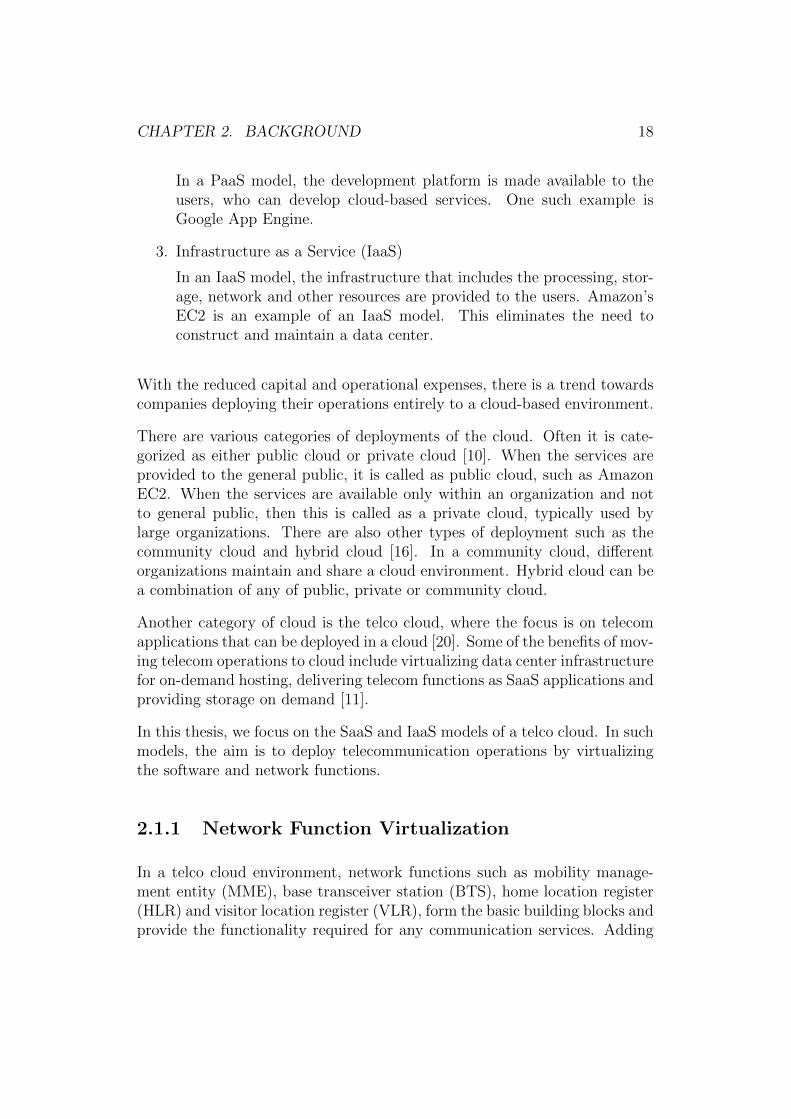
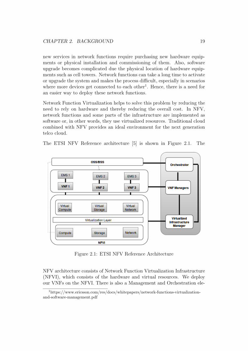
The ETSI NFV Reference architecture [5] is shown in Figure 2.1. The
Figure 2.1: ETSI NFV Reference Architecture
NFV architecture consists of Network Function Virtualization Infrastructure(NFVI), which consists of the hardware and virtual resources. We deployour VNFs on the NFVI. There is also a Management and Orchestration ele-
1https://www.ericsson.com/res/docs/whitepapers/network-functions-virtualization-and-software-management.pdf
CHAPTER 2. BACKGROUND 20
ment that performs the resource allocations in NFVI, life cycle managementof VNFs and overall orchestration. The functionality of these components isexplained below.
The Network Function Virtualization Infrastructure (NFVI) consistsof all the hardware resources such as compute, storage and network ele-ments. The virtualization layer creates a hardware abstraction of the re-sources below. Above this, we have the virtual compute element, virtualstorage element and virtual network element. We see that NFVI consists ofthe hardware, virtualization layer as well as the virtual resources that arenecessary to launch a VNF.
Above the NFVI, we have the Virtualized Network Functions (VNF)which are basically software packages that can implement the network func-tions (such as routers and firewalls) using the infrastructure provided bythe NFVI. Each VNF is connected to an Element Management System(EMS) that manages the operations of the VNF.
The OSS and BSS refer to the operational and the business support systemsof a mobile network operator (MNO).
The Management and Orchestration block consists of the VirtualizedInfrastructure Manager (VIM), VNF Managers and the Orchestrator. TheVIM manages and controls the interaction of NFVI to the VNFs. It performsthe resource management and also analyses the performance of NFVI. TheVNF Managers help the VNFs to instantiate, update, scale and terminate,and they also perform other critical functions that are necessary for the entireVNF life cycle. The Orchestrator performs global management of NFVI andpolicy management for the network services.
2.2 Need for Trust in the Cloud
With the advancements in the area of cloud and NFV, enterprises have con-sidered deploying their services on the cloud. However, one of the majorchallenges they face is the lack of trust. The notion of trust is an importantfactor to consider, especially when we run mission critical components on thecloud.
In [49], the authors have considered various definitions of trust as a socialconcept as well as in a digital environment. Ko et al. [28] define trust in cloud
CHAPTER 2. BACKGROUND 21
as the confidence that we place in the cloud. In an IaaS model, the wordtrust can be associated with the confidence that we place on infrastructureproviders i.e. the belief that our data is protected and our services in cloudare working in an expected manner. In such scenarios, trust often refers tothe integrity of the system.
In all the service models of cloud, users do not have control over the infras-tructure and they are often required to trust the infrastructure providers [41].Chow et al. [12] emphasize the lack of control of data in the cloud, which isone of reasons why some enterprises do not move their operations into thecloud. Also, organizations that require data protection policies are requiredto know how the data is managed and also to know if there have been anychanges made to it [37]. Hence, transparency of data control and securityguarantees are crucial for placing trust in the cloud.
With the growing use of virtualization technologies, the users and the serviceproviders have to trust the cloud providers. Zhang et al. [53] consider cloudsecurity as one of the main topic areas of research and trusting the infras-tructure as one of the important challenges faced by the cloud users. Theauthors state that the infrastructure provider must provide confidentialityand auditability to the service provider to ensure secure data transfer andintegrity of the data. The authors further stress on the need for a trustedhardware and trusted virtualization layer.
In [41], the authors highlight the set of attacks possible in a cloud environ-ment. For example, they explain the possibility of an attacker to retrieve con-fidential information such as passwords, certificates, private keys and othercritical information from the cloud. Their attacks mostly deal with attackingthe VM such as capturing VM snapshots, analyzing memory dump of VM,attacks performed on VM migration. The authors also list the possibilityof circumventing the current protections in the cloud environment; however,they do not propose a solution or mitigation for the specified attacks.
In [15], the authors explain the challenges of IaaS such as the level of truston the infrastructure provider, data control, data integrity verification andVM integrity. The paper also provides a method to secure virtual machineimages by encrypting it in the client side. However, the proposed methoddoes not enhance trust in infrastructure providers.
Dawoud et al. [14] provide a list of challenges associated with trust in IaaSand also lists the possible solutions to address these challenges. Accordingto the authors, one of the critical components in an IaaS is the Service Level
CHAPTER 2. BACKGROUND 22
Agreements (SLA). SLAs detail the benefits and responsibilities of the serviceprovider and infrastructure provider. The IaaS providers are not supposed toviolate the SLAs or the requirements of the service providers. This is crucialin scenarios, such as, lawful interception where there is a legal requirementto launch the services in a specific geographic location. In such scenarios, itis important to have a clear list of policies concerning the SLAs, especiallyin cases of VM migration and evacuation. Preserving SLAs is a criticalcomponent in a telco cloud environment as well.
The aspect of trust has also been considered in other cloud infrastructuressuch as in mobile cloud [25]. Survey papers focusing on cloud security suchas [14], [48], [19], [12] and [21], have discussed the aspect of trust with respectto IaaS and the necessity to introduce trusted computing technologies in theinfrastructure. Yang et al [51] discuss about security in NFV and have con-sider trust management as a security challenge. In [53], the authors highlightthe necessity to introduce TPM to the hardware and also motivates the needto have multiple layers of trust in the architecture.
It is evident from the above sources that trust is an important factor to beconsidered in a cloud environment and especially for IaaS model. A solutionspecified in the above papers is to use trusted computing technologies, whichprovides a method to enable trust by verifying the integrity of the platform.
2.3 Trusted Computing Concepts
Trusted Computing defines a set of technologies that can provide trustedplatforms [43], and hence, reducing the level of blind trust the users have onthe cloud infrastructure providers. Such technologies leverage the use of theTrusted Platform Module (TPM) chip in its hardware layer. In this section,we will look into the TPM architecture and explain how such technologiesprovide a trusted platform.
2.3.1 Trusted Platform Module Architecture
Trusted Platform Module2 (TPM) is a micro-controller that is capable ofstoring keys, passwords, certificates and other confidential data. TPM can
2http://www.trustedcomputinggroup.org/trusted-platform-module-tpm-summary/
CHAPTER 2. BACKGROUND 23
Figure 2.2: Trusted Platform Module Architecture
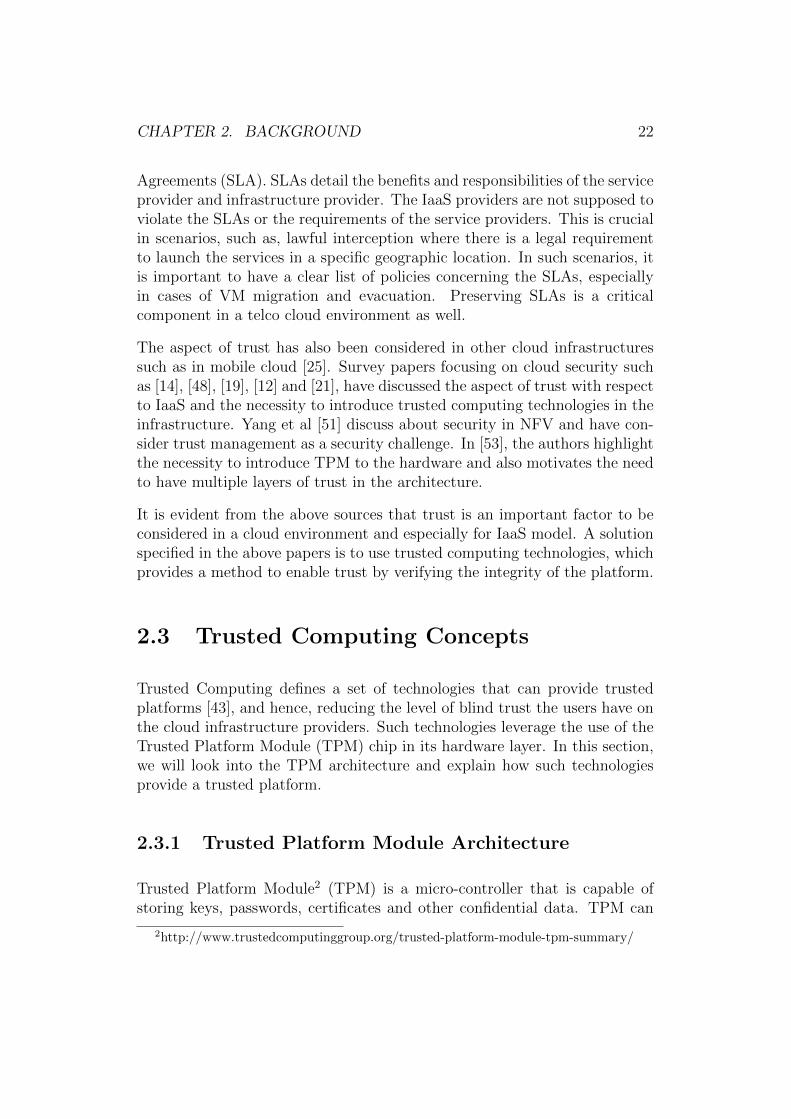
be used for secure storage, to verify the integrity of the platform and alsodisk encryption. TPM is often embedded onto the motherboard of serversor PCs. The basic components of a TPM version 1.2 [1] are shown in Figure2.2.
The I/O Buffer is the area between the host system and the TPM. Thesystem sends the request and retrieves the response through this buffer. Thenon-volatile memory stores the state associated with the TPM. The TPMchecks if the value it stores is same as that of the values in the non-volatilestorage. This component must be in a protected area and should have re-stricted access. TPM uses random numbers while creating signatures, noncesand also in keys. The random number generator has components suchas entropy functions, mixing functions and state registers to ensure the ran-domness.
The Platform Configuration Registers (PCRs) are registers that containthe measurements of various components such as BIOS, hypervisor and oper-ating system. Measurements are cryptographic hashes of these componentsand are stored in PCRs. Each TPM has 24 PCR registers numbered 0-23.Each PCR register has the capacity to store 20 bytes in it. PCR Registers0-7 store the measurement values of ROM and the BIOS. PCR 8-16 storesthe measurement values of the OS-related files. PCR 18 stores the value ofthe hypervisor and PCR 22 stores the measurement of a Geo-location trustcertificate and related entities.
The SHA-1 Engine performs the hash function used by the TPM to take the
CHAPTER 2. BACKGROUND 24
hash of the measured values. In this scenario, we use the SHA-1 algorithm.The Attestation Identity Key (AIK) or simply known as the AttestationKey is generally used for the signing procedures. The key generation com-ponent produces two keys. One is the ordinary key that is generated by theRNG. The other is the primary key that is generated using the seed value.The Program Code executes the TPM commands and also ensures the in-tegrity of PCRs. The RSA Engine performs the 2048 bit RSA encryptionand decryption operations.
2.3.2 Platform Trust Through Boot Time Measure-ment
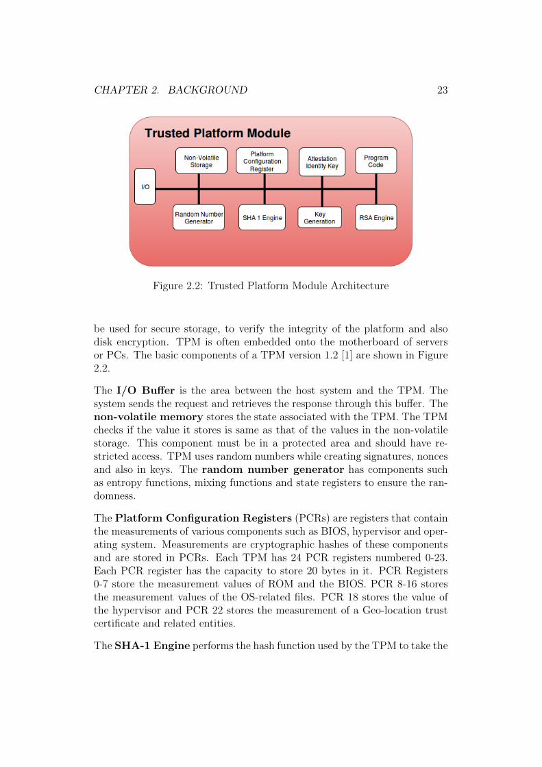
Platform trust during the boot time can be achieved with the use of TPM. Asmentioned previously, the PCR registers in TPM store cryptographic hashesof software components such as the BIOS, boot loader, OS and hypervisor.In this section, we explain this process using the Intel TXT terminology.Intel TXT is a hardware technology from Intel which aims to provide rootof trust and verify the integrity of platform [22].
Figure 2.3: Chain of Trust
The Trusted Computing Base (TCB) refers to the set of platform specificcomponents which are crucial for measuring the trust level of the system.
CHAPTER 2. BACKGROUND 25
TXT provides a Measured Launch Environment (MLE), which verifies themeasurement values of these components based on known good values.
The Core root of trust Measurement (CRTM) is the first set of code executedduring boot. During the initial boot, the CRTM measures BIOS and writesthe hash to the PCRs 0-4. Then it transfers the control to BIOS. BIOSmeasures the boot loader, writes to PCRs 5-7 and transfers control to theboot loader. The boot loader measures the operating system, writes to PCRs8-15 and gives control to the OS. The OS would perform this operation on thehypervisor, and so on forming a chain of trust [29], [46]. This is as depictedin Figure 2.3.
During a trusted boot, these components are measured and verified againstknown good values. If this chain is broken, then the system is halted oris started according to the launch control policies (LCP) specified by theadmin. Launch Control Policies are the list of policies that verifies if thesystem meets the required criteria and further decides if the system has tobe booted or not. This is a static root of trust measurement. If there hasbeen any changes in measurement values after establishing the trust, due tonew components or upgrades, then the TPM has to be reset.
2.3.3 External Attestation Process
Verifying the platform trust is achieved during the system boot. However,in a telco cloud environment, after the NFVI boot the service provider maywant to verify the platform configurations before launching its VNFs. Insuch scenarios, we require an external attestation mechanism that can provethe trust of a remote platform.
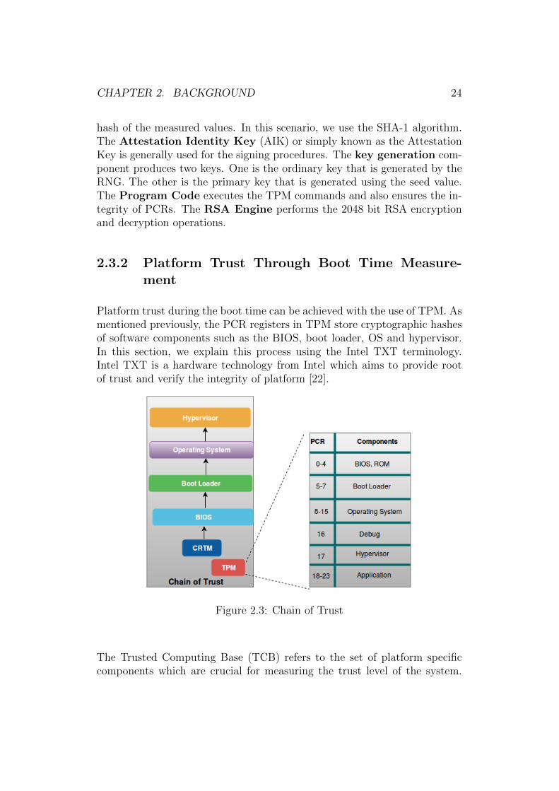
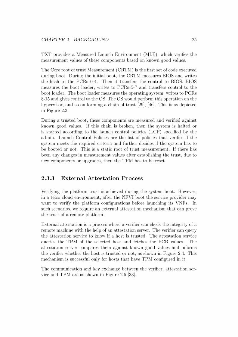
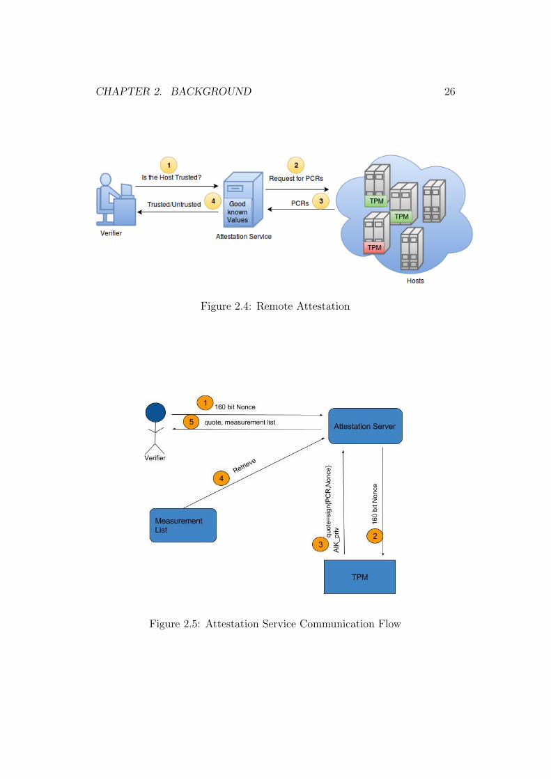
External attestation is a process where a verifier can check the integrity of aremote machine with the help of an attestation server. The verifier can querythe attestation service to know if a host is trusted. The attestation servicequeries the TPM of the selected host and fetches the PCR values. Theattestation server compares them against known good values and informsthe verifier whether the host is trusted or not, as shown in Figure 2.4. Thismechanism is successful only for hosts that have TPM configured in it.
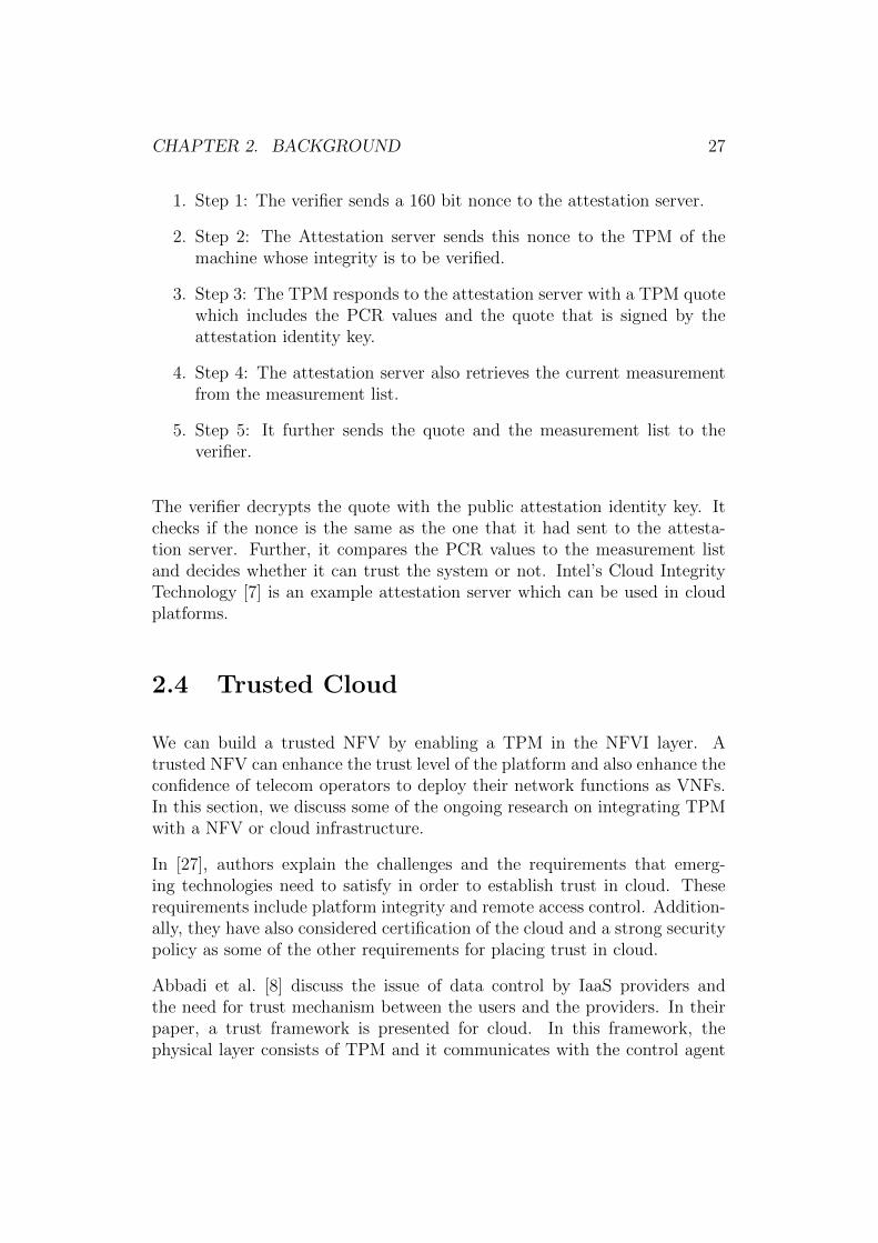
The communication and key exchange between the verifier, attestation ser-vice and TPM are as shown in Figure 2.5 [33].
CHAPTER 2. BACKGROUND 26
Figure 2.4: Remote Attestation
Figure 2.5: Attestation Service Communication Flow
CHAPTER 2. BACKGROUND 27
1. Step 1: The verifier sends a 160 bit nonce to the attestation server.
2. Step 2: The Attestation server sends this nonce to the TPM of themachine whose integrity is to be verified.
3. Step 3: The TPM responds to the attestation server with a TPM quotewhich includes the PCR values and the quote that is signed by theattestation identity key.
4. Step 4: The attestation server also retrieves the current measurementfrom the measurement list.
5. Step 5: It further sends the quote and the measurement list to theverifier.
The verifier decrypts the quote with the public attestation identity key. Itchecks if the nonce is the same as the one that it had sent to the attesta-tion server. Further, it compares the PCR values to the measurement listand decides whether it can trust the system or not. Intel’s Cloud IntegrityTechnology [7] is an example attestation server which can be used in cloudplatforms.
2.4 Trusted Cloud
We can build a trusted NFV by enabling a TPM in the NFVI layer. Atrusted NFV can enhance the trust level of the platform and also enhance theconfidence of telecom operators to deploy their network functions as VNFs.In this section, we discuss some of the ongoing research on integrating TPMwith a NFV or cloud infrastructure.
In [27], authors explain the challenges and the requirements that emerg-ing technologies need to satisfy in order to establish trust in cloud. Theserequirements include platform integrity and remote access control. Addition-ally, they have also considered certification of the cloud and a strong securitypolicy as some of the other requirements for placing trust in cloud.
Abbadi et al. [8] discuss the issue of data control by IaaS providers andthe need for trust mechanism between the users and the providers. In theirpaper, a trust framework is presented for cloud. In this framework, thephysical layer consists of TPM and it communicates with the control agent
CHAPTER 2. BACKGROUND 28
so as to monitor the operational status of the cloud. The authors aim tocreate a chain of trust between the user and the cloud provider, although,it seems to be an extended version of trust establishment based on remoteattestation process.
In [45], the authors present a mechanism to verify the integrity of a VM. Thisis achieved by introducing a cloud verifier component that attests the VM,and the process involves key exchange between the user and the cloud verifier.Further, they devise a functionality to encrypt the image and decrypt it whena request arrives. The authors claim that this gives enough proof to the userthat their VM is launched in a trusted hardware. However, verifying theintegrity of VM images during launch time is not considered. Also, a strongevaluation of this mechanism is missing from their paper.
Previously, we have discussed SLAs and the need to protect them. A com-mon SLA between the user and the cloud provider is to enforce data pro-tection by defining geographic boundaries to the data as mentioned in [26].In such conditions, the VM migration or evacuation might not be possible ifit violates the geographic policy specified by the user. However, in a cloudenvironment with many VMs running, the IaaS providers do not provideany verification mechanism that the VMs are actually functioning accord-ing to the policies specified. In [26], the authors further discuss engineeringa middle-ware system that can assert the integrity of the components andto verify if geographic trust is maintained. This is achieved by introducingTPM in the hardware and maintaining a hardware root of trust. The paperdiscusses more challenges associated with ensuring geographic trust.
Yan et al. [50], presented a trust framework for network function virtualiza-tion and 5G security. The authors use trusted computing technologies in theNFVI layer, so as to preserve trust in the platform. Further, they have atrust management middle layer and trust functions running on top of NFVI.However, they have not evaluated the framework with the requirements theyhave specified and also an implementation of this framework is missing.
In [37], authors have focused on implementing trust in cloud by using trustedcomputing technologies. The proposed system’s functionality is similar totraditional trusted boot mechanism and remote attestation. The authorshave included the aspect of logging in-order to monitor and detect tampering.
There have been efforts on virtualizing the TPM, commonly known as vTPM[39], [44]. vTPM is helpful during migration where we can migrate the vTPMalong with the VM. This guarantees a flexible migration process and provides
CHAPTER 2. BACKGROUND 29
an easier way to do an integrity check after migration. However, this processis complicated. vTPM has to measure components in the new platform,which results in a failure as vTPM would contain the old cryptographic keysor associated data against the specified VM [42].
There has been significant work done on establishing trust in cloud throughtrusted computing technologies. Technologies such as Intel TXT [22] andIntel’s Software Guard Extensions (Intel SGX)3 are being used in real worldcloud scenarios.
However, it is still insufficient to solve the challenges in a telco cloud envi-ronment. In this thesis, we aim to establish trust in NFV and address thechallenges associated with it.
2.5 Summary
In this Chapter, we have explained the concepts of cloud computing andNFV. We explored the need for placing trust in such environments. Further,we have discussed the existing trusted computing technologies and their func-tionality. In the last section, we have looked into the existing research thatcombines trusted computing in cloud-based systems.
3https://software.intel.com/en-us/sgx
Chapter 3
Challenges in Providing Trust inNFV
In this chapter, we explain the challenges in providing trust in NFV. Thechallenges include providing platform trust for NFVI, developing VNF in-tegrity verification mechanisms, resource management in NFV and fault tol-erance. Firstly, we explain the terminology associated with trust and ourassumptions. Next, we look into these challenges in detail.
3.1 Terminology
In this section, we introduce and clarify the terminology associated withNFVI, VNF and trust.
NFVI States:
1. NFVI BootThis refers to the boot process of a single NFVI host. In trusted envi-ronment, the NFVI integrity is verified during this stage.
2. NFVI RunThis refers to the state of NFVI where it is functional and is capableto launch a VNF. To verify the trust status of an NFVI element duringits run time, we can use the remote attestation mechanisms.
30
CHAPTER 3. CHALLENGES IN PROVIDING TRUST IN NFV 31
3. NFVI TerminateThis state occurs when the NFVI encounters a shut down due to crashor for maintenance purposes. When a trusted NFVI hosting sensitiveworkload encounters this state, all the workload needs to be migratedto another trusted platform residing in trusted compute pool.
4. NFVI CrashThe NFVI can move to a crash state when any of its components stopsfunctioning correctly.
VNF States:
1. VNF LaunchThis state refers to the processing of request to launch the VNFs. Ahost is selected during this phase that match the requirements of aVNF.
2. VNF BootThis refers to the boot process of individual VNFs. A VNF can alsobe booted in a trusted way by verifying its integrity.
3. VNF RunThis refers to the running state of a VNF where the network functionsstart to operate.
4. VNF SuspendVNF can enter into a suspend state when we want to save the currentstate of the VNF and resume during a later point in time. When a VNFis suspended, its virtual storage disk should be encrypted in order toavoid sensitive data leakage. The encryption and decryption keys canbe secured by storing them in TPM.
5. VNF SnapshotA snapshot is a VNF system state at a particular time. A snapshot ofa VNF can be loaded as a new image.
6. VNF MigrationThis process involves the movement of running VNFs from one NFVIto another including its memory, compute and storage.
7. VNF EvacuationVNF evacuation is the process of forced migration. This operation isperformed during emergency situations such as NFVI crash.
CHAPTER 3. CHALLENGES IN PROVIDING TRUST IN NFV 32
8. VNF CrashA VNF can crash due to failure in VNF components or the NFVI.VNF crashes can be mitigated using fail-over or backup mechanismsbut the data associated with crashed VNF needs to be securely deletedor evacuated in order to avoid unauthorized access to it.
Terminology Associated with Trust:
We now define the terminology associated with the notion of trust dependingon the platform and location of NFVI.
1. Platform TrustThe term platform trust implies the state of NFVI where the integrityof all critical components such as BIOS, OS and hypervisor is preserved.For VNFs that require only platform trust, it is free to start, migrateor evacuate on a trusted machine as long as the integrity of platformcomponents is preserved.
2. Geographic TrustGeographic trust implies the geo-location trust of NFVI. This is criti-cal in cases of VNFs such as Lawful Interception (LI), where the VNFsare expected to be launched in specified geographic location. In suchscenarios, the VNFs may be restricted to migrate or evacuate to othergeographic locations that are not mentioned in the service level agree-ments.
In a telco cloud environment, the service providers may have to run criticalVNFs that impose geographic restrictions. In such scenarios, we require boththe platform trust as well as geographic trust. In such conditions, the VNFscan be migrated or evacuated to another trusted machine but in the samegeographic area.
We define trust as a process of ensuring that the integrity of the system ispreserved or maintained. Integrity of platform components affect the place-ment of VNFs. In this thesis, we introduce two new terms, the hard trustand soft trust. If the VNFs require hard trust, it implies that the VNFscan be launched only if all the components of the system are trusted. Suchpolicies of trust can lead to difficulties during migration and evacuation whenthere are no trusted resources and this eventually leads to deliberate killingof the VNFs. However, soft trust allows mitigations and the VNFs can be
CHAPTER 3. CHALLENGES IN PROVIDING TRUST IN NFV 33
launched irrespective of trusted hosts and later have the flexibility to migrateto more suitable trusted host. Such mechanisms preserve SLAs and are easierto perform migration and evacuation of the VNFs.
3.2 VNF-VM Assumption
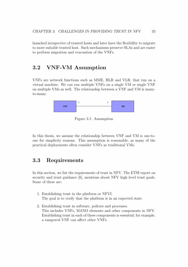
VNFs are network functions such as MME, HLR and VLR, that run on avirtual machine. We can run multiple VNFs on a single VM or single VNFon multiple VMs as well. The relationship between a VNF and VM is many-to-many.
Figure 3.1: Assumption
In this thesis, we assume the relationship between VNF and VM is one-to-one for simplicity reasons. This assumption is reasonable, as many of thepractical deployments often consider VNFs as traditional VMs.
3.3 Requirements
In this section, we list the requirements of trust in NFV. The ETSI report onsecurity and trust guidance [6], mentions about NFV high level trust goals.Some of these are:
1. Establishing trust in the platform or NFVI.The goal is to verify that the platform is in an expected state.
2. Establishing trust in software, policies and processes.This includes VNFs, MANO elements and other components in NFV.Establishing trust in each of these components is essential; for example,a tampered VNF can affect other VNFs.

CHAPTER 3. CHALLENGES IN PROVIDING TRUST IN NFV 34
3. Supplying guidance for operational environment such as MANO andEMS, that is critical in decision making.
4. Defining trust relationships between virtualization resources for trustlife-cycle management.
In the ETSI report they have also stressed on the measures that needto be taken during a trust failure. Some of the options they haveconsidered are:
5. Inform the failure to another trusted entity
6. Increasing the logging levels
7. Reducing operational parameters
8. Other options include to work normal, cease the operation or destroy
Consolidating the above goals, we derive the following requirements to es-tablish trust in NFV.
1. The NFVI must be trusted and a mechanism is needed to verify this.
2. NFVI must ensure that the quality of service (QoS) of VNFs are met.This implies that NFVI should aim to preserve SLAs and minimize theoccurrence of failure.
3. NFVI should verify the trust status of VNFs before launching.
4. An external needs to audit the actions of NFVI
3.4 Challenges
NFV is a relatively new concept and there are numerous challenges associ-ated with it. However, only a few existing literatures have discussed on thechallenges of incorporating trust in NFV.
The ETSI white paper [4] on NFV details the challenges associated withNFV. They consider security and resilience as some of the challenges, how-ever, they do not explicitly state trust as a challenge. Similarly in [23], the
CHAPTER 3. CHALLENGES IN PROVIDING TRUST IN NFV 35
authors consider only security as one of the challenges but do not considerthe aspects of trust in NFV.
Based on the requirements that we have considered earlier, we see that trustis an essential aspect that needs to be incorporated in NFV in each of itslayers. We need to consider the platform trust and trust of VNFs. We alsoneed to consider resource management and fault tolerance aspects, which arecritical to such environment. In this section, we explain these challenges indetail.
3.4.1 Platform Trust
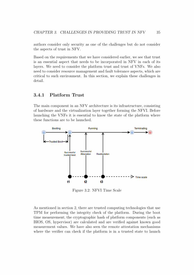
The main component in an NFV architecture is its infrastructure, consistingof hardware and the virtualization layer together forming the NFVI. Beforelaunching the VNFs it is essential to know the state of the platform wherethese functions are to be launched.
Figure 3.2: NFVI Time Scale
As mentioned in section 2, there are trusted computing technologies that useTPM for performing the integrity check of the platform. During the boottime measurement; the cryptographic hash of platform components (such asBIOS, OS, hypervisor) are calculated and are verified against known goodmeasurement values. We have also seen the remote attestation mechanismswhere the verifier can check if the platform is in a trusted state to launch
CHAPTER 3. CHALLENGES IN PROVIDING TRUST IN NFV 36
a VNF. The prover guarantees this by obtaining the PCR values from theTPM through a secure communication.
In Figure 3.2, we show the time-scale associated with NFVI. t1 representsthe point in time during which the system is running and had undergonea successful trusted boot. t2 represents the point in time where the NFVIis successfully attested by the attestation service. Here, during the timeinterval between the points t1 and t2, we can say that the NFVI element istrusted by itself. During time interval between points t2 and t3, we say thatthe element is trusted by the cloud as it is verified by the attestation service.However, this degree of trust can degrade over time, especially in a cloudscenario when reboot of NFVI does not take place often. In such scenarios,we need a re-attestation marked by t3 in the figure.
Although re-attestation can be guaranteed, the values loaded in TPM areduring the boot time. Hence, even if there is a change in integrity measure-ments of NFVI, it can only be detected during the next boot time, i.e, afterrestarting the system. Therefore, re-attestation does not guarantee the fresh-ness of trust level. To solve this we require run time attestation mechanisms.Currently, there has been limited works on run-time attestation of NFVI andit remains an open challenge.
3.4.2 VNF Integrity Verification
Consider a scenario where company A sells its cloud infrastructure to com-pany B. Company B may verify the integrity of the platform with the helpof trusted computing technologies. However, it has no way to guarantee thatVNF supplied by Company A is not tampered with.
Verifying the integrity of VNFs during its launch-time is crucial to establishtrust in NFV. During VNF launch-time, a VNF image is selected by thehypervisor. It might be possible that the VNF image has been tampered orcorrupted. For example, it takes only a few seconds to add a malware tothese VNF images. Such VNFs, if launched, can affect the functioning of theentire system and also of other VNFs.
In [31], the authors describe a method of secure cloud computing by verifyingthe freshness of the VM image. However, this does not prevent from insiderattacks and also does not provide user-data confidentiality.
CHAPTER 3. CHALLENGES IN PROVIDING TRUST IN NFV 37
OpenStack 1 will be having an image signing feature in its next release Mi-taka, but they do not consider scenarios where the image server is compro-mised, which might lead the attacker to create fake signatures.
To establish trust in VNF, we need to address the following challenges
1. How to encrypt or sign a VNF
2. How to verify integrity of VNFs
3. How to prevent insider attacks
3.4.3 Launch VNFs on Specific NFVI
In a telco cloud, the service providers may want their VNFs to run only onservers with certain platform configurations, such as specific BIOS version,OS type etc.
In traditional PC, an analogous to this problem is addressed by using thetechnique of CPU pinning where the processes are bound to specific CPUsand are allowed to execute only on them. In a cloud scenario, CPU pinningrefers to the pinning of virtual CPUs (vCPUs) of VNFs to the physical CPUsof the host [24]. This is useful in scenarios where two guest vCPUs competefor CPU time of the host, which might lead to high latency of the work loadrunning on the VNFs. CPU pinning avoids this latency by allocating vCPUsto specific threads in the host, thereby, balancing the workload executing onthe vCPU and efficiently using the cache2. While this solution can guaranteethe SLA of running VNFs on certain physical CPUs, it does not let theservice provider know the state of the platform.
Binding VNFs to NFVI require policies that should be satisfied for the bind-ing to be successful. The policies would contain the platform configurationsthat the NFVI must possess in order to launch the VNF. In [13], the authorsbroadly describe the policies that are required in provisioning of a virtualnetwork operations center. However, the patent does not provide any mech-anism for the start-up of VNFs. Also, it does not provide a method to bind
1https://specs.openstack.org/openstack/glance-specs/specs/liberty/image-signing-and-verification-support.html
2https://specs.openstack.org/openstack/nova-specs/specs/juno/approved/virt-driver-cpu-pinning.html
CHAPTER 3. CHALLENGES IN PROVIDING TRUST IN NFV 38
VNFs the TPM. Zhang et al, [54], explains the need for restricting accessfrom one Xen based VM to another Xen based VM. Here, they specify apolicy that details which pairings of VM can communicate with each other.However, this IPR does not address the policies required for VM startupmechanism nor the VNF-NFVI binding.
In order to solve the challenge of VNF-NFVI binding, we need to address thefollowing:
1. How to understand if a VNF requires binding
2. How to retrieve the platform configuration state of NFVI
3. To implement the binding mechanism and the policies associated withthis
4. A mechanism to verify the binding rules before launching any VNFs
In chapter 5, we solve this problem using an external verifier and having apolicy mechanism in place.
3.4.4 Resource Management
Mijumbi et al. [36] explain the challenges associated with NFV Managementand Orchestration. One of the challenges mentioned is the resource manage-ment, in particular, the problem of identifying a host to launch the VNFs.This problem gets more complicated in trusted NFV environment where werequire trusted hosts to launch VNFs.
The host selection process is performed based on criteria that the user wantswhile launching an instance. For example, the user can specify that theyneed 1GB RAM, host is functional and it is trusted. Also, there can beadditional custom requirements. In order to guarantee a QoS for the VNFs,it is important to meet the VNF requirement by the NFVI. The question tobe solved is how do we select a host M where image i can be instantiated.
The selection of trusted hosts is possible and there are practical implementa-tions in Openstack. There are also concepts of Trusted Computing Pools in
CHAPTER 3. CHALLENGES IN PROVIDING TRUST IN NFV 39
OpenStack 3, that are based on Intel TXT4. Here, the machines with TPMsupport form a pool of trusted resources. The user can specify to launch theirVNF on a trusted environment and the infrastructure provider provides withone of the machines in the trusted pool where the VNF can be launched.
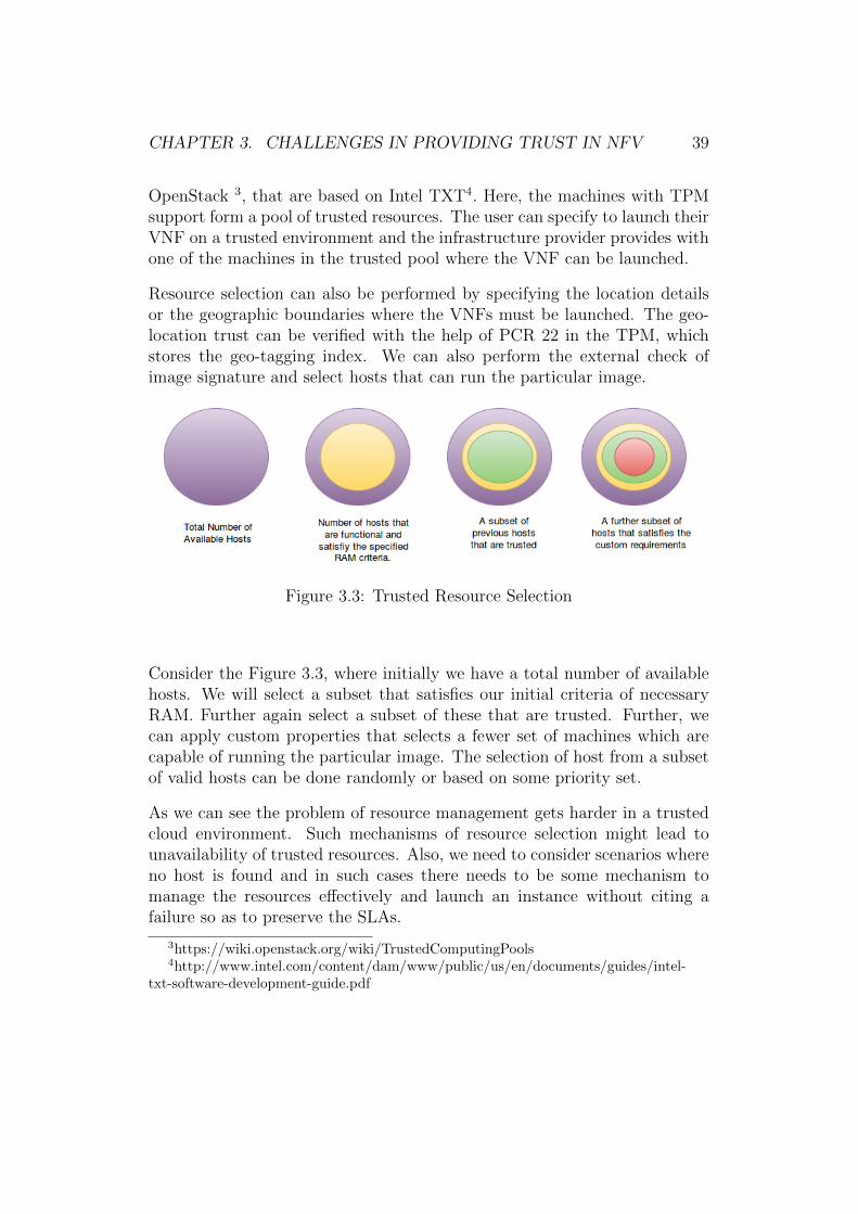
Resource selection can also be performed by specifying the location detailsor the geographic boundaries where the VNFs must be launched. The geo-location trust can be verified with the help of PCR 22 in the TPM, whichstores the geo-tagging index. We can also perform the external check ofimage signature and select hosts that can run the particular image.
Figure 3.3: Trusted Resource Selection
Consider the Figure 3.3, where initially we have a total number of availablehosts. We will select a subset that satisfies our initial criteria of necessaryRAM. Further again select a subset of these that are trusted. Further, wecan apply custom properties that selects a fewer set of machines which arecapable of running the particular image. The selection of host from a subsetof valid hosts can be done randomly or based on some priority set.
As we can see the problem of resource management gets harder in a trustedcloud environment. Such mechanisms of resource selection might lead tounavailability of trusted resources. Also, we need to consider scenarios whereno host is found and in such cases there needs to be some mechanism tomanage the resources effectively and launch an instance without citing afailure so as to preserve the SLAs.
3https://wiki.openstack.org/wiki/TrustedComputingPools4http://www.intel.com/content/dam/www/public/us/en/documents/guides/intel-
txt-software-development-guide.pdf
CHAPTER 3. CHALLENGES IN PROVIDING TRUST IN NFV 40
3.4.5 Fault Tolerance
Fault tolerance is yet another unexplored area in a trusted cloud scenario.We consider a system has failed when the user is not able to launch a VNFdue to unavailability of resources. The current systems have focused on faultavoidance; however, it prevents the system from functioning during a failure.In such scenarios, it is necessary to consider fault tolerance aspects.
Dobson et al [17] have mentioned that it is an unrealistic approach to dependon a system based on fault prevention alone. The authors have also empha-sized on the need to have fault tolerance mechanisms in practice. In [32] theauthors explain the design requirements for an NFV system. Although, thearticle does not cover the requirements we stated in Chapter 3, it mentionsfault tolerance as one of the requirements.
In an NFV environment, VNFs may demand various platform specific re-quirements. In such scenarios the service providers should be able to decidethe platform configuration and the hardware selection before launching theVNFs [30]. Some VNFs would require certain guaranteed geographic loca-tions where it can be launched. Some critical VNFs would need trustedplatform while others might just want to be launched and may be migrateto trusted platform later.
Considering these cases, we have come up with the scenarios where we requirea fault tolerance or in other words mitigations to the failure scenarios.
1. Unavailability of resources that satisfy the platform specific conditionsset by a VNF
2. VNF integrity is compromised
3. Binding of VNF to NFVI resulted in failure
4. NFVI is not trusted
5. NFVI does not meet the required platform policies for launching a VNF
In order to guarantee fault tolerance during failure scenarios, we need toconsider the above cases and provide a mitigation during these events. Im-plementing a fault tolerance approach has the potential to solve the resourcemanagement problem that we have previously discussed.
CHAPTER 3. CHALLENGES IN PROVIDING TRUST IN NFV 41
3.5 Summary
In this chapter, we described the various terminologies associated with trust,NFVI and VNF. Further, we have looked into the challenges of establishingtrust in NFV. We have explored challenges such as platform trust, VNFintegrity verification, VNF-NFVI binding, resource management and faulttolerance in an NFV environment.
Chapter 4
Architecture and Design
This chapter gives an overview of the system architecture and its components.We have modified the ETSI NFV architecture to build trusted NFV. Furtherwe have developed two mechanisms: signing and VNF-TPM binding. Thesigning mechanism performs the VNF integrity checks and the VNF-TPMbinding mechanism achieves the VNF-VNFI binding. We explain the processof resource selection in specific to OpenStack. Also, we propose a policy-based fault tolerance method.
4.1 Modified ETSI NFV Architecture
We have constructed a system that introduces new components, such as, theTPM, Trusted Security Orchestrator (TSecO) and the attestation server tothe existing NFV architecture, as shown in Figure 4.1. In our architecture theNFVI consists of servers with TPM chip that enables the boot time integrityverification of NFVI. Above this layer, we have the host operating systemand further up the stack we have the hypervisor. Above the hypervisor layerwe deploy the network functions(MME, HLR, VLR) as VNFs. We introducethe TSecO and the attestation service to the management and orchestrationstack of NFV.
To explain the communication links between the components, we use Open-Stack with QEMU(Quick EMUlator) as the hypervisor, which communicateswith the TSecO. The host operating system consists of a trust agent whichcan securely communicate with the attestation server. We use Intel’s CIT
42
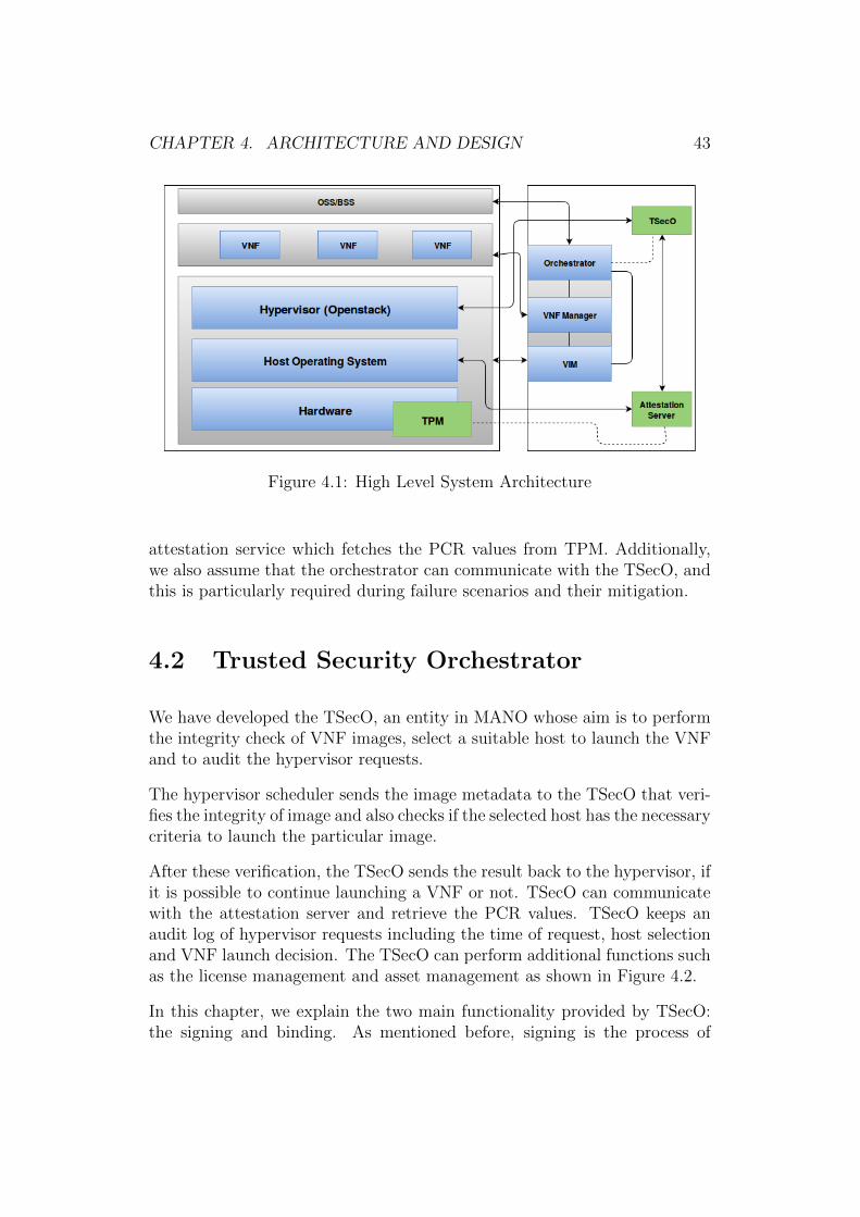
CHAPTER 4. ARCHITECTURE AND DESIGN 43
Figure 4.1: High Level System Architecture
attestation service which fetches the PCR values from TPM. Additionally,we also assume that the orchestrator can communicate with the TSecO, andthis is particularly required during failure scenarios and their mitigation.
4.2 Trusted Security Orchestrator
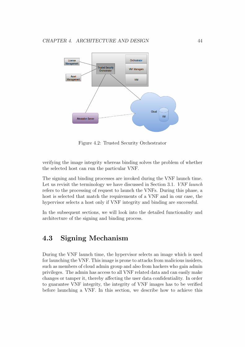
We have developed the TSecO, an entity in MANO whose aim is to performthe integrity check of VNF images, select a suitable host to launch the VNFand to audit the hypervisor requests.
The hypervisor scheduler sends the image metadata to the TSecO that veri-fies the integrity of image and also checks if the selected host has the necessarycriteria to launch the particular image.
After these verification, the TSecO sends the result back to the hypervisor, ifit is possible to continue launching a VNF or not. TSecO can communicatewith the attestation server and retrieve the PCR values. TSecO keeps anaudit log of hypervisor requests including the time of request, host selectionand VNF launch decision. The TSecO can perform additional functions suchas the license management and asset management as shown in Figure 4.2.
In this chapter, we explain the two main functionality provided by TSecO:the signing and binding. As mentioned before, signing is the process of
CHAPTER 4. ARCHITECTURE AND DESIGN 44
Figure 4.2: Trusted Security Orchestrator
verifying the image integrity whereas binding solves the problem of whetherthe selected host can run the particular VNF.
The signing and binding processes are invoked during the VNF launch time.Let us revisit the terminology we have discussed in Section 3.1. VNF launchrefers to the processing of request to launch the VNFs. During this phase, ahost is selected that match the requirements of a VNF and in our case, thehypervisor selects a host only if VNF integrity and binding are successful.
In the subsequent sections, we will look into the detailed functionality andarchitecture of the signing and binding process.
4.3 Signing Mechanism
During the VNF launch time, the hypervisor selects an image which is usedfor launching the VNF. This image is prone to attacks from malicious insiders,such as members of cloud admin group and also from hackers who gain adminprivileges. The admin has access to all VNF related data and can easily makechanges or tamper it, thereby affecting the user data confidentiality. In orderto guarantee VNF integrity, the integrity of VNF images has to be verifiedbefore launching a VNF. In this section, we describe how to achieve this
CHAPTER 4. ARCHITECTURE AND DESIGN 45
Figure 4.3: Creating a Signature File
Figure 4.4: Verification of Signature
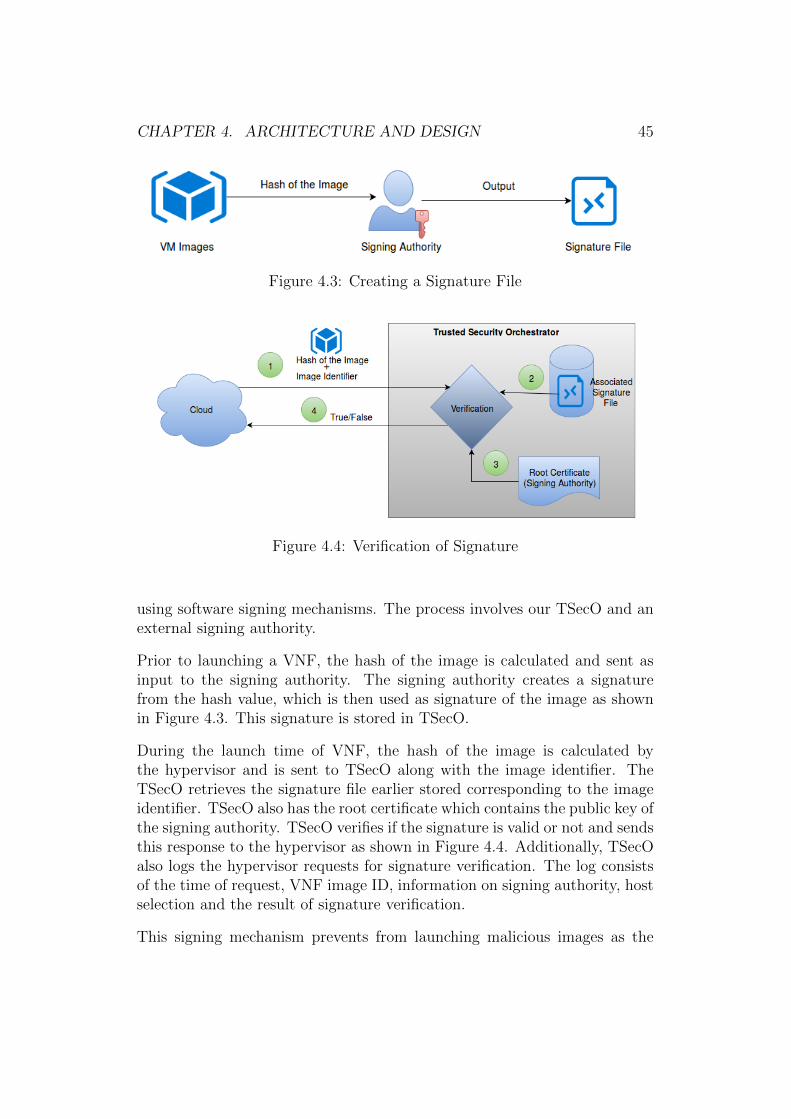
using software signing mechanisms. The process involves our TSecO and anexternal signing authority.
Prior to launching a VNF, the hash of the image is calculated and sent asinput to the signing authority. The signing authority creates a signaturefrom the hash value, which is then used as signature of the image as shownin Figure 4.3. This signature is stored in TSecO.
During the launch time of VNF, the hash of the image is calculated bythe hypervisor and is sent to TSecO along with the image identifier. TheTSecO retrieves the signature file earlier stored corresponding to the imageidentifier. TSecO also has the root certificate which contains the public key ofthe signing authority. TSecO verifies if the signature is valid or not and sendsthis response to the hypervisor as shown in Figure 4.4. Additionally, TSecOalso logs the hypervisor requests for signature verification. The log consistsof the time of request, VNF image ID, information on signing authority, hostselection and the result of signature verification.
This signing mechanism prevents from launching malicious images as the
CHAPTER 4. ARCHITECTURE AND DESIGN 46
signature verification in TSecO would result in a failure for tampered images.Also, such a mechanism is helpful in proving the ownership of VNF images.Having an external signing authority and verification mechanism reduces thepossibilities for insider attacks. For example, if a fake admin tries to launcha malicious VNF, it would fail the signature verification and hence preventsfrom launching the VNF. It is indeed possible for the fake admin to proceedto host selection irrespective of the result from TSecO. However, once thehypervisor sends request to the TSecO for signature verification, the externallog in TSecO stores all the necessary information and hence it is easier todetect if there has been any malicious activity. As discussed in Chapter3, the existing literatures perform the signature verification of VNF imagesinternally, but does not consider insider attackers as potential threats. Webelieve having an external signing mechanism provides an efficient way toattest the VNF integrity and log the integrity status.
4.4 VNF-TPM Binding Mechanism
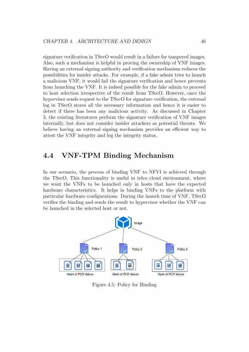
In our scenario, the process of binding VNF to NFVI is achieved throughthe TSecO. This functionality is useful in telco cloud environment, wherewe want the VNFs to be launched only in hosts that have the expectedhardware characteristics. It helps in binding VNFs to the platform withparticular hardware configurations. During the launch time of VNF, TSecOverifies the binding and sends the result to hypervisor whether the VNF canbe launched in the selected host or not.
Figure 4.5: Policy for Binding

CHAPTER 4. ARCHITECTURE AND DESIGN 47
Figure 4.6: VNF-TPM Binding Process
The process of binding is performed by associating the image with one ormore policies. Each policy consists of combinations of PCR registers and wetake a hash of the concatenated PCR values, which is stored in TSecO asshown in Figure 4.5.
During the verification process, the hypervisor communicates with the TSecOby providing the image identifier and host name. The TSecO fetches thecurrent PCR values corresponding to the policy elements and calculates theconcatenated hash of the retrieved values. TSecO compares this against theknown good hash values that are already stored against the selected policy.If the hashes match, the binding is considered to be successful. This result iscommunicated back to the hypervisor as shown in Figure 4.6. If the bindingfails, the hypervisor does not launch the VNF. Similar to signing mechanism,the TSecO logs details related to binding, such as VNF image identifier,time of request, host selection and the result of binding. This method allows
CHAPTER 4. ARCHITECTURE AND DESIGN 48
combinations of PCR values to be taken into consideration and hence VNFcan be associated with more specific policies. To our knowledge there areno existing works on policy-based approach for VNF-NFVI binding. Thismethod helps to launch VNF on the platform that has certain hardwareconfigurations and such mechanisms are necessary especially in a telco cloudenvironment.
4.5 Resource Selection
4.5.1 Modified Filter Scheduler in OpenStack
To facilitate the communication between hypervisor and TSecO, we use theconcept of filters in OpenStack. Filters in the OpenStack scheduler find themost fitting host to launch a VNF. Some of the available filters are RAMfilter, compute filter etc. for checking the available memory and CPU coresand to select hosts based on these factors to launch the VNF. Additionally,OpenStack allows the possibility to create custom filters, which we use inthis thesis to communicate with the TSecO. In this section, we describe theprocess of filtering in OpenStack.
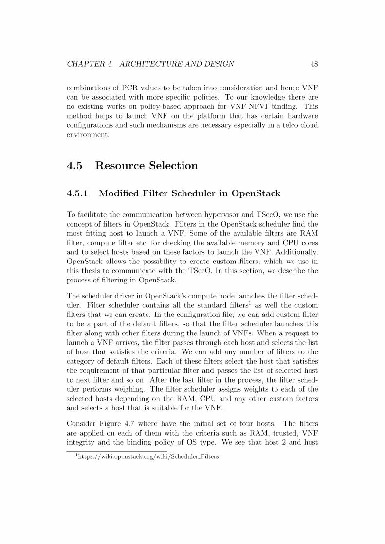
The scheduler driver in OpenStack’s compute node launches the filter sched-uler. Filter scheduler contains all the standard filters1 as well the customfilters that we can create. In the configuration file, we can add custom filterto be a part of the default filters, so that the filter scheduler launches thisfilter along with other filters during the launch of VNFs. When a request tolaunch a VNF arrives, the filter passes through each host and selects the listof host that satisfies the criteria. We can add any number of filters to thecategory of default filters. Each of these filters select the host that satisfiesthe requirement of that particular filter and passes the list of selected hostto next filter and so on. After the last filter in the process, the filter sched-uler performs weighing. The filter scheduler assigns weights to each of theselected hosts depending on the RAM, CPU and any other custom factorsand selects a host that is suitable for the VNF.
Consider Figure 4.7 where have the initial set of four hosts. The filtersare applied on each of them with the criteria such as RAM, trusted, VNFintegrity and the binding policy of OS type. We see that host 2 and host
1https://wiki.openstack.org/wiki/Scheduler Filters
CHAPTER 4. ARCHITECTURE AND DESIGN 49
Figure 4.7: OpenStack Filter Scheduler
Figure 4.8: OpenStack Resource Selection Process
CHAPTER 4. ARCHITECTURE AND DESIGN 50
4 fail to satisfy the filtering rules. After the filtering, weighting is appliedto host 1 and host 3 to select the best of two. The weighting rule in thisscenario depends on the RAM. The host that has more memory is selectionand this case it is host 3.
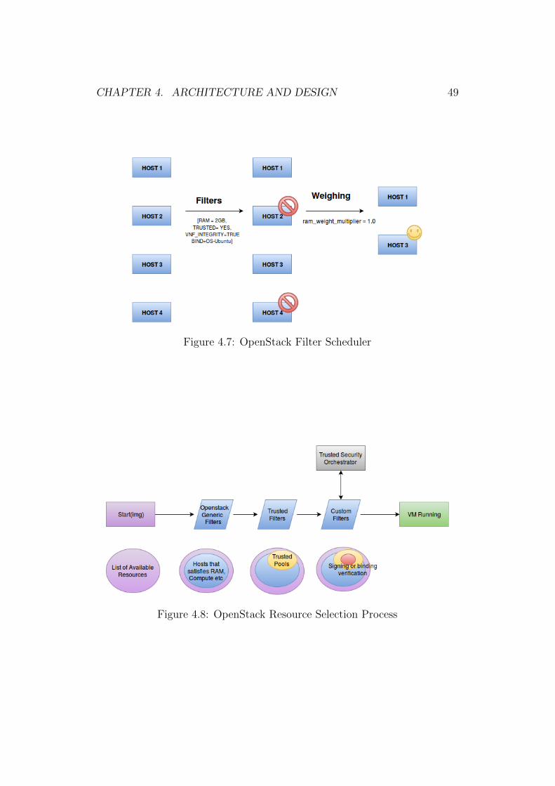
The resource selection architecture in our scenario is as shown in Figure 4.8.We use the custom filters for sending the image identifiers and hostname tothe TSecO. It receives the status of signing and binding from TSecO anddoes not launch the VNF if TSecO returns a False. We also see the processof resource selection in OpenStack which is similar to challenge we discussedin section 3.
4.5.2 Modified OpenStack’s Architecture:Launch of VNF Instance
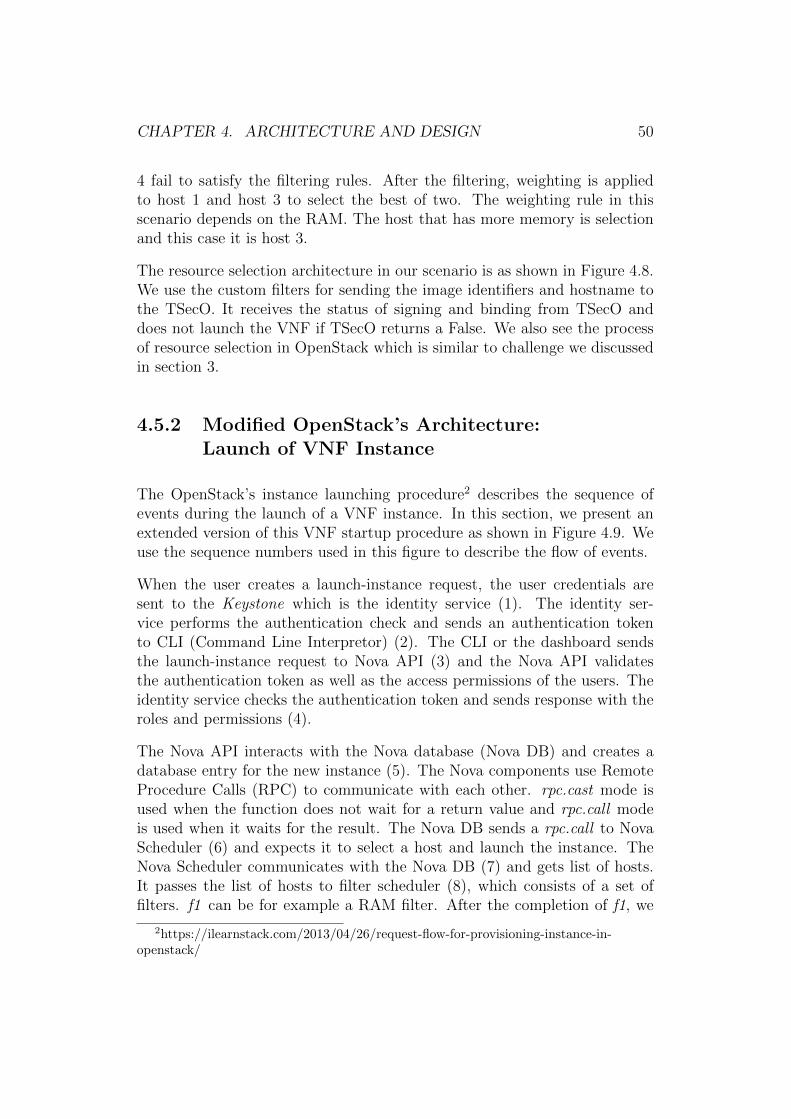
The OpenStack’s instance launching procedure2 describes the sequence ofevents during the launch of a VNF instance. In this section, we present anextended version of this VNF startup procedure as shown in Figure 4.9. Weuse the sequence numbers used in this figure to describe the flow of events.
When the user creates a launch-instance request, the user credentials aresent to the Keystone which is the identity service (1). The identity ser-vice performs the authentication check and sends an authentication tokento CLI (Command Line Interpretor) (2). The CLI or the dashboard sendsthe launch-instance request to Nova API (3) and the Nova API validatesthe authentication token as well as the access permissions of the users. Theidentity service checks the authentication token and sends response with theroles and permissions (4).
The Nova API interacts with the Nova database (Nova DB) and creates adatabase entry for the new instance (5). The Nova components use RemoteProcedure Calls (RPC) to communicate with each other. rpc.cast mode isused when the function does not wait for a return value and rpc.call modeis used when it waits for the result. The Nova DB sends a rpc.call to NovaScheduler (6) and expects it to select a host and launch the instance. TheNova Scheduler communicates with the Nova DB (7) and gets list of hosts.It passes the list of hosts to filter scheduler (8), which consists of a set offilters. f1 can be for example a RAM filter. After the completion of f1, we
2https://ilearnstack.com/2013/04/26/request-flow-for-provisioning-instance-in-openstack/
CHAPTER 4. ARCHITECTURE AND DESIGN 51
Figure 4.9: Provisioning VNFs: Modified Architecture
CHAPTER 4. ARCHITECTURE AND DESIGN 52
receive a set of hosts that has the required RAM to run the instance (9). f2can be for example the trust filter. This performs the check if the host istrusted i.e. the instance requires only the hosts that are trusted.
We then pass these trusted hosts to our custom filters (10). In our scenario,the custom filter sends the image metadata and host name to the TrustedSecurity Orchestrator (TSecO) that we have developed (11). As mentionedbefore, the TSecO performs the VNF integrity checks and VNF-TPM bindingprocedures. For example, TSecO can communicate with the signing authorityfor signature verification (12-13). It also communicates with the attestationserver (14-15) for the binding process. After the verification process, TSecOsends the response to the custom filter (16). If all the filters return a truevalue, the filter scheduler provides the set of hosts to the weighing component(17). This component allocates weights to the hosts and selects the best host.The host with the maximum weight is selected and in this case, it is Compute2. The name of selected host is sent back to the filter scheduler (18).
The filter scheduler provides the selected hostname Compute 2 and its iden-tifier to the Nova Scheduler (19). The Nova Scheduler sends this response toNova API (20). The Nova Scheduler sends an rpc.cast to Compute 2 nodeto launch the instance (21) and Compute 2 node sends rpc.call to the con-ductor, in order to provide the instance information such as RAM, CPU,disk etc. (22). The conductor interacts with the Nova DB and retrieves therequired values (23) and this information is then sent to the Nova Compute(24).
The compute node interacts with the Nova image component to retrieve theimage URI via glance API (25). The Nova image component validates theauthentication token with the identity service (26). The glance API fetchesthe image URI from the Nova image component and sends them to the com-pute node (27). Further, the compute node communicates with the Novanetwork component through the network API (28). The quantum serverchecks the authentication token and it gets the required network resourcesto start the instance (29). The compute node gets the required network in-formation (30) and it communicates with the Nova block-storage componentvia the cinder API to attach the volumes to instances (31). The cinder APIvalidates the authentication token with the identity service (32) and com-municates with the Nova block-storage service to retrieve the block storageinformation. The compute node gets the block storage information to attachvolumes to instances (33) and it can now communicate with the hypervisordriver to execute the request (34).

CHAPTER 4. ARCHITECTURE AND DESIGN 53
To conclude, in this section we looked into the case of provisioning a VNFand how different components interact in our modified architecture.
4.6 Fault Tolerance Based on
Policy Mechanism
As seen from Figure 4.8, the problem of resource selection becomes compli-cated with the introduction of trusted filter as well as custom filters. Therecan be situations where there are no trusted resources available, and thismight lead to problems in launching as well as migration and evacuation ofVNFs.
We introduce a policy-based mechanism to address this problem. As seenfrom the VNF-TPM binding, we associate each image to one or more policiesand each policy is a combination of PCRs. If none of the policies are satisfied,this can lead to unavailability of resources. However, it is possible to find a setof one or more sub-policies that might satisfy parts of the requirement. Forexample, consider the case where the strongest policy does not successfullycomplete the binding. In such scenarios, it might be possible to launch theVNF with the next set of policies that satisfy the requirement. This wouldrequire communication between TSecO and orchestrator so as to launch theVNF with minimal policy but with certain set of protection such as networkmonitoring of VNFs.
We depict this as a partially ordered set of policies as shown in Figure 4.10.Consider a mechanism where the policy strength depends on the length ofpolicies and, if the strongest policy is not available then we can select oneof the next strongest policies available from the lattice. From the Figure4.10, the strongest policy is {0, 17, 18, 22} as it has the maximum policylength. Here, {0, 17, 18, 22} corresponds to the PCR values of BIOS, OS,hypervisor and geo-location trust respectively, and the least being φ. If thepolicy {0, 17, 18, 22} fails, and the policy {0, 17, 18} is successful, itis possible to launch the VNF with the latter policy provided there are somemitigations. In the above example, if the geo-location trust is not guaranteed,it might be possible to migrate the VNF to nearest geographic location withnetwork monitoring in place.
The real challenge here is to determine the policy strength. Since this is apartial order problem, it is difficult to define the policy strength in cases of
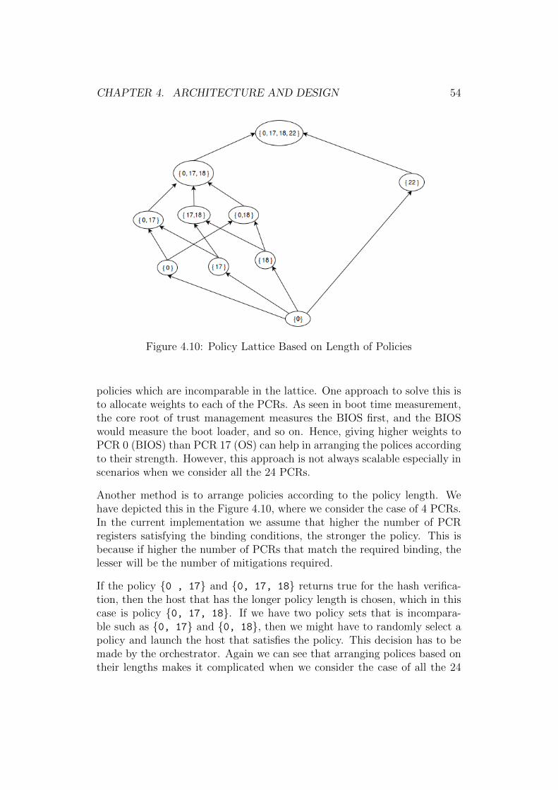
CHAPTER 4. ARCHITECTURE AND DESIGN 54
Figure 4.10: Policy Lattice Based on Length of Policies
policies which are incomparable in the lattice. One approach to solve this isto allocate weights to each of the PCRs. As seen in boot time measurement,the core root of trust management measures the BIOS first, and the BIOSwould measure the boot loader, and so on. Hence, giving higher weights toPCR 0 (BIOS) than PCR 17 (OS) can help in arranging the polices accordingto their strength. However, this approach is not always scalable especially inscenarios when we consider all the 24 PCRs.
Another method is to arrange policies according to the policy length. Wehave depicted this in the Figure 4.10, where we consider the case of 4 PCRs.In the current implementation we assume that higher the number of PCRregisters satisfying the binding conditions, the stronger the policy. This isbecause if higher the number of PCRs that match the required binding, thelesser will be the number of mitigations required.
If the policy {0 , 17} and {0, 17, 18} returns true for the hash verifica-tion, then the host that has the longer policy length is chosen, which in thiscase is policy {0, 17, 18}. If we have two policy sets that is incompara-ble such as {0, 17} and {0, 18}, then we might have to randomly select apolicy and launch the host that satisfies the policy. This decision has to bemade by the orchestrator. Again we can see that arranging polices based ontheir lengths makes it complicated when we consider the case of all the 24
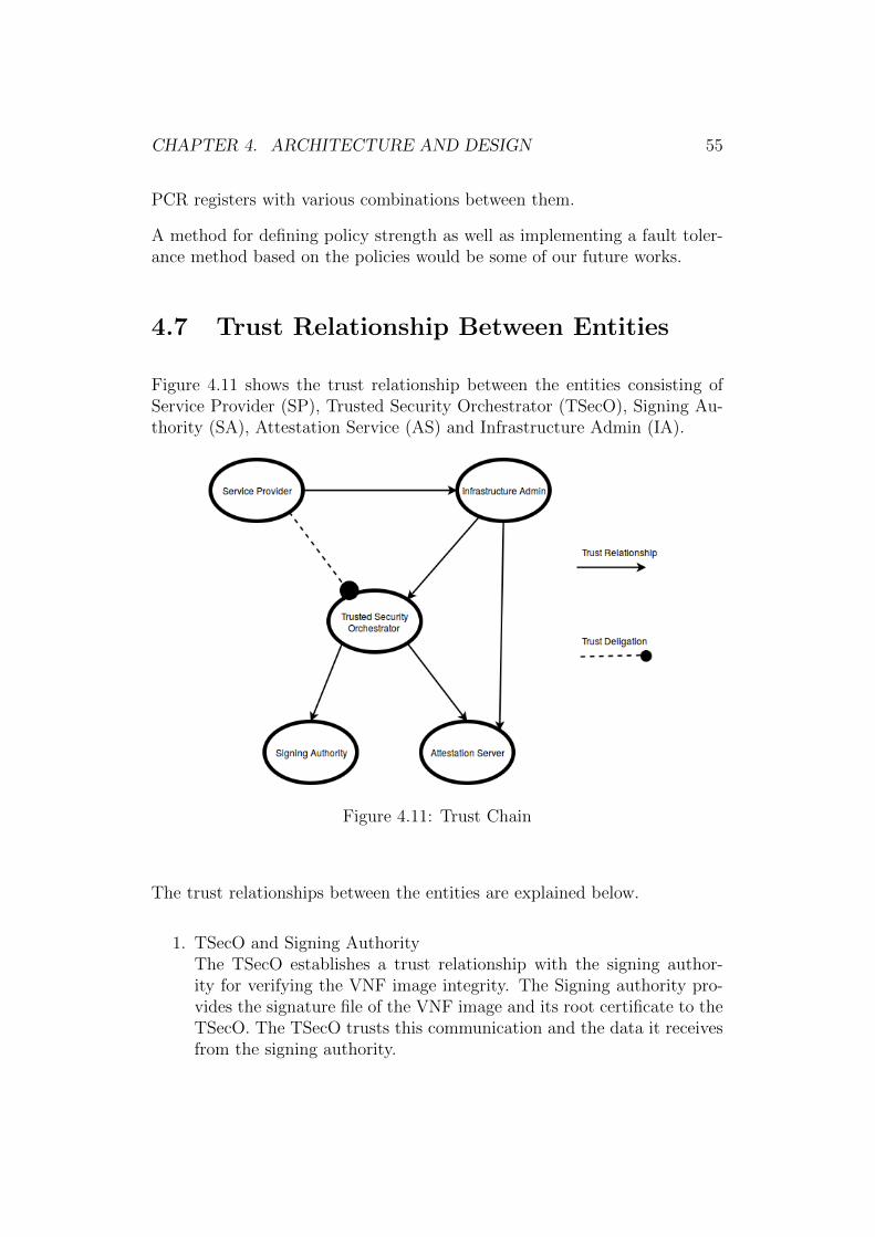
CHAPTER 4. ARCHITECTURE AND DESIGN 55
PCR registers with various combinations between them.
A method for defining policy strength as well as implementing a fault toler-ance method based on the policies would be some of our future works.
4.7 Trust Relationship Between Entities
Figure 4.11 shows the trust relationship between the entities consisting ofService Provider (SP), Trusted Security Orchestrator (TSecO), Signing Au-thority (SA), Attestation Service (AS) and Infrastructure Admin (IA).
Figure 4.11: Trust Chain
The trust relationships between the entities are explained below.
1. TSecO and Signing AuthorityThe TSecO establishes a trust relationship with the signing author-ity for verifying the VNF image integrity. The Signing authority pro-vides the signature file of the VNF image and its root certificate to theTSecO. The TSecO trusts this communication and the data it receivesfrom the signing authority.
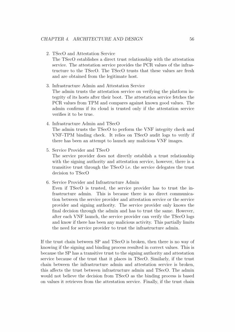
CHAPTER 4. ARCHITECTURE AND DESIGN 56
2. TSecO and Attestation ServiceThe TSecO establishes a direct trust relationship with the attestationservice. The attestation service provides the PCR values of the infras-tructure to the TSecO. The TSecO trusts that these values are freshand are obtained from the legitimate host.
3. Infrastructure Admin and Attestation ServiceThe admin trusts the attestation service on verifying the platform in-tegrity of its hosts after their boot. The attestation service fetches thePCR values from TPM and compares against known good values. Theadmin confirms if its cloud is trusted only if the attestation serviceverifies it to be true.
4. Infrastructure Admin and TSecOThe admin trusts the TSecO to perform the VNF integrity check andVNF-TPM binding check. It relies on TSecO audit logs to verify ifthere has been an attempt to launch any malicious VNF images.
5. Service Provider and TSecOThe service provider does not directly establish a trust relationshipwith the signing authority and attestation service, however, there is atransitive trust through the TSecO i.e. the service delegates the trustdecision to TSecO
6. Service Provider and Infrastructure AdminEven if TSecO is trusted, the service provider has to trust the in-frastructure admin. This is because there is no direct communica-tion between the service provider and attestation service or the serviceprovider and signing authority. The service provider only knows thefinal decision through the admin and has to trust the same. However,after each VNF launch, the service provider can verify the TSecO logsand know if there has been any malicious activity. This partially limitsthe need for service provider to trust the infrastructure admin.
If the trust chain between SP and TSecO is broken, then there is no way ofknowing if the signing and binding process resulted in correct values. This isbecause the SP has a transitive trust to the signing authority and attestationservice because of the trust that it places in TSecO. Similarly, if the trustchain between the infrastructure admin and attestation service is broken,this affects the trust between infrastructure admin and TSecO. The adminwould not believe the decision from TSecO as the binding process is basedon values it retrieves from the attestation service. Finally, if the trust chain
CHAPTER 4. ARCHITECTURE AND DESIGN 57
between SP and admin is broken then SP would not believe the final decision,although it can verify the audit logs of TSecO.
The trust chain helps in viewing the high level picture and the trust relation-ship between the entities. We see that the longer the trust chains are, themore fragile is the architecture. However, the aim of this thesis is to buildtechniques to enhance VNF trust, VNF placement and to address other is-sues, such as, resource management and fault tolerance. Hence, we are notfocusing on building an end-to-end trust.
4.8 Use Cases
Following are some of use cases of trusted computing, signing, VNF-TPMbinding mechanism and the fault tolerance approach.
1. Lawful Interception
Lawful interceptions are the legal policies to intercept a communicationor network traffic [3]. These are usually targeted at suspected criminals,and the information collected is used by legal authorities for analysis.LI components usually have conditions on the platform where it is runand also on the geographic locations. The VNF which provides theLI functionality must guarantee that it runs on a platform with thespecified conditions. Using the VNF-TPM binding mechanism, we canensure that the VNF is mapped to specific platform configurations andverify if it is possible to launch the VNF in it. This guarantees theplacement of VNFs in the correct platform and avoid launching it if itviolates the legal policies. Also, we include PCR 22 on the VNF-TPMbinding if the VNFs require geo-location trust.
2. Safety-Critical VNFs
Safety Critical VNFs such as Medical VNFs, Telecommunication soft-ware, Firewalls etc. needs to be started irrespective of the platform theyare launched on. Using the VNF-TPM binding, if there are no availableplatforms that satisfy all the requirements, there are other policies thatmight satisfy parts of the requirement. The list of policies for a VNFmakes it possible to launch a VNF in a platform with a certain level ofguarantees. Also, verifying the integrity of such critical VNFs is alsonecessary and we can achieve this using the signing method.
CHAPTER 4. ARCHITECTURE AND DESIGN 58
3. Digital Rights Management
Digital Rights Management (DRM) defines the policies, techniques andtools for managing the digital content [47]. Our VNF-TPM bindingmechanisms will be useful in scenarios where VNFs require DRM. Theprovider can define custom policies that would enforce VNFs to starton a particular platform and refuse to launch if the policies do notmatch.
4. Edge Computing
Edge computing refers to placing the network functionality, such as,mobile network base stations away from the centralized nodes to thenetwork edge3. This allows easier physical access when managed indata center and therefore there is a high possibility for attack. Havingtrusted computing technologies can help to detect if there has beenany unauthorized modifications made to the system. Also an externalsigning mechanism can help in verifying the integrity of VNFs to belaunched in such networks.
5. Data Sovereignty
Consider a scenario where the Russian personal data needs to be storedin servers within the EU [40]. In such situations, the main concern isassociated with privacy and integrity of the data. Data Sovereigntyrefers to the sensitive data flow outside a nation’s border and aims toisolate particular section of cloud to the rest of the infrastructure. Insuch scenarios, using remote attestation can guarantee the trust statusof the infrastructure. Also, methods such as VNF signing and VNF-TPM binding can prove the ownership and integrity of the VNFs.
4.9 Summary
In this chapter, we have looked into the system architecture that we haveproposed in order to solve the challenges of placing trust in NFV. We havedesigned two mechanisms: signing and VNF-TPM binding. Further, wealso propose a policy based fault tolerance approach to solve the resourcemanagement problem. Additionally, we have also discussed the trust chainbetween entities and the use cases of the signing and binding mechanisms.
3http://www.etsi.org/technologies-clusters/technologies/mobile-edge-computing
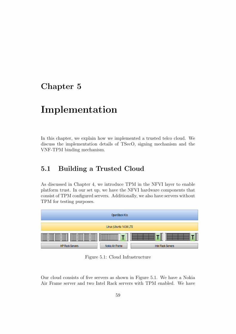
Chapter 5
Implementation
In this chapter, we explain how we implemented a trusted telco cloud. Wediscuss the implementation details of TSecO, signing mechanism and theVNF-TPM binding mechanism.
5.1 Building a Trusted Cloud
As discussed in Chapter 4, we introduce TPM in the NFVI layer to enableplatform trust. In our set up, we have the NFVI hardware components thatconsist of TPM configured servers. Additionally, we also have servers withoutTPM for testing purposes.
Figure 5.1: Cloud Infrastructure
Our cloud consists of five servers as shown in Figure 5.1. We have a NokiaAir Frame server and two Intel Rack servers with TPM enabled. We have
59
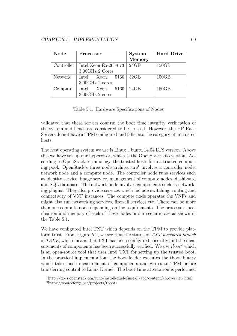
CHAPTER 5. IMPLEMENTATION 60
Node Processor SystemMemory
Hard Drive
Controller Intel Xeon E5-2658 v33.00GHz 2 Cores
24GB 150GB
Network Intel Xeon 51603.00GHz 2 cores
32GB 150GB
Compute Intel Xeon 51603.00GHz 2 cores
24GB 150GB
Table 5.1: Hardware Specifications of Nodes
validated that these servers confirm the boot time integrity verification ofthe system and hence are considered to be trusted. However, the HP RackServers do not have a TPM configured and falls into the category of untrustedhosts.
The host operating system we use is Linux Ubuntu 14.04 LTS version. Abovethis we have set up our hypervisor, which is the OpenStack kilo version. Ac-cording to OpenStack terminology, the trusted hosts form a trusted comput-ing pool. OpenStack’s three node architecture1 involves a controller node,network node and a compute node. The controller node runs services suchas identity service, image service, management of compute nodes, dashboardand SQL database. The network node involves components such as network-ing plugins. They also provide services which include switching, routing andconnectivity of VNF instances. The compute node operates the VNFs andmight also run networking services, firewall services etc. There can be morethan one compute node depending on the requirements. The processor spec-ification and memory of each of these nodes in our scenario are as shown inthe Table 5.1.
We have configured Intel TXT which depends on the TPM to provide plat-form trust. From Figure 5.2, we see that the status of TXT measured launchis TRUE, which means that TXT has been configured correctly and the mea-surements of components has been successfully verified. We use tboot2 whichis an open-source tool that uses Intel TXT for setting up the trusted boot.In the practical implementation, the boot loader executes the tboot binarywhich takes hash measurement of components and writes to TPM beforetransferring control to Linux Kernel. The boot-time attestation is performed
1http://docs.openstack.org/juno/install-guide/install/apt/content/ch overview.html2https://sourceforge.net/projects/tboot/
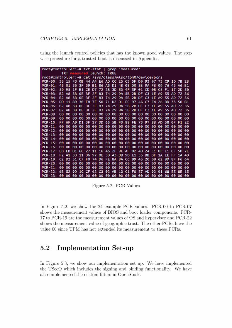
CHAPTER 5. IMPLEMENTATION 61
using the launch control policies that has the known good values. The stepwise procedure for a trusted boot is discussed in Appendix.
Figure 5.2: PCR Values
In Figure 5.2, we show the 24 example PCR values. PCR-00 to PCR-07shows the measurement values of BIOS and boot loader components. PCR-17 to PCR-19 are the measurement values of OS and hypervisor and PCR-22shows the measurement value of geographic trust. The other PCRs have thevalue 00 since TPM has not extended its measurement to these PCRs.
5.2 Implementation Set-up
In Figure 5.3, we show our implementation set up. We have implementedthe TSecO which includes the signing and binding functionality. We havealso implemented the custom filters in OpenStack.
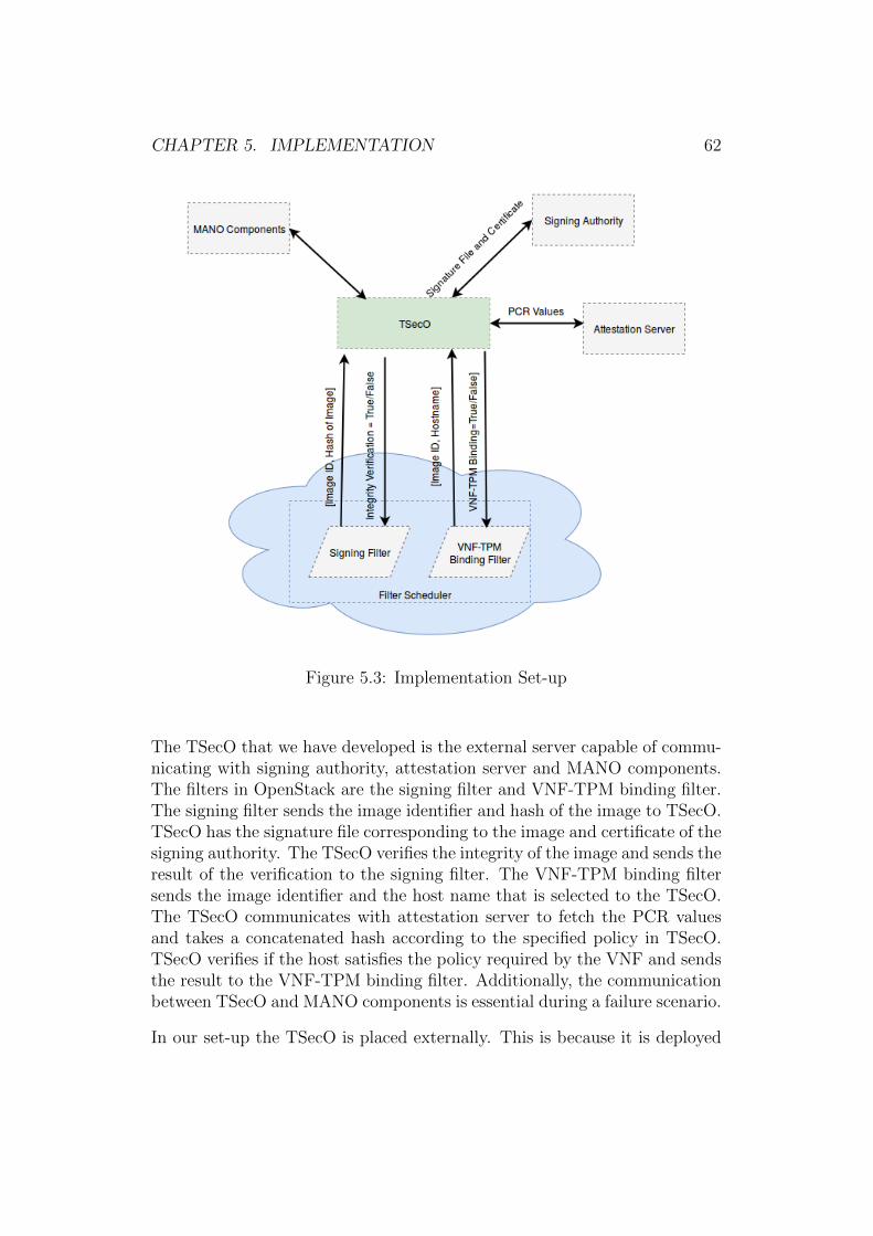
CHAPTER 5. IMPLEMENTATION 62
Figure 5.3: Implementation Set-up
The TSecO that we have developed is the external server capable of commu-nicating with signing authority, attestation server and MANO components.The filters in OpenStack are the signing filter and VNF-TPM binding filter.The signing filter sends the image identifier and hash of the image to TSecO.TSecO has the signature file corresponding to the image and certificate of thesigning authority. The TSecO verifies the integrity of the image and sends theresult of the verification to the signing filter. The VNF-TPM binding filtersends the image identifier and the host name that is selected to the TSecO.The TSecO communicates with attestation server to fetch the PCR valuesand takes a concatenated hash according to the specified policy in TSecO.TSecO verifies if the host satisfies the policy required by the VNF and sendsthe result to the VNF-TPM binding filter. Additionally, the communicationbetween TSecO and MANO components is essential during a failure scenario.
In our set-up the TSecO is placed externally. This is because it is deployed
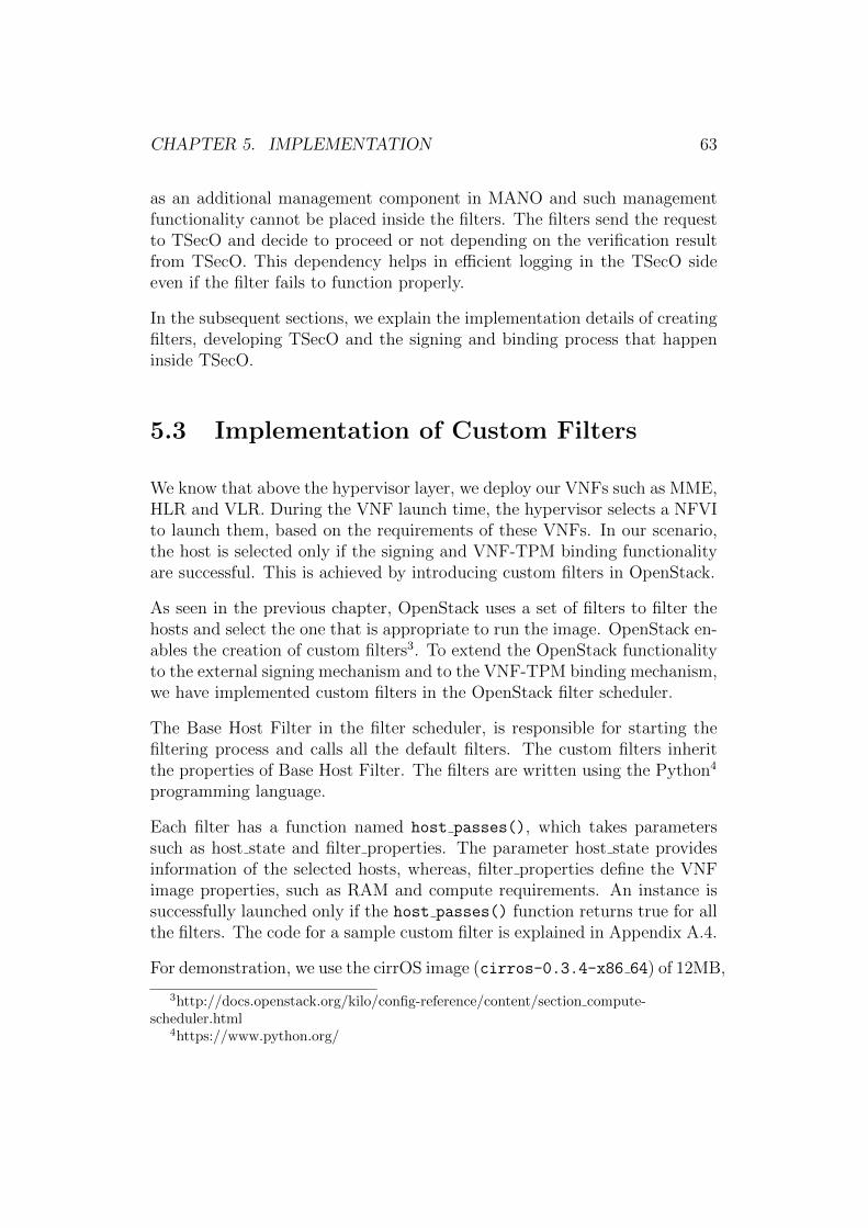
CHAPTER 5. IMPLEMENTATION 63
as an additional management component in MANO and such managementfunctionality cannot be placed inside the filters. The filters send the requestto TSecO and decide to proceed or not depending on the verification resultfrom TSecO. This dependency helps in efficient logging in the TSecO sideeven if the filter fails to function properly.
In the subsequent sections, we explain the implementation details of creatingfilters, developing TSecO and the signing and binding process that happeninside TSecO.
5.3 Implementation of Custom Filters
We know that above the hypervisor layer, we deploy our VNFs such as MME,HLR and VLR. During the VNF launch time, the hypervisor selects a NFVIto launch them, based on the requirements of these VNFs. In our scenario,the host is selected only if the signing and VNF-TPM binding functionalityare successful. This is achieved by introducing custom filters in OpenStack.
As seen in the previous chapter, OpenStack uses a set of filters to filter thehosts and select the one that is appropriate to run the image. OpenStack en-ables the creation of custom filters3. To extend the OpenStack functionalityto the external signing mechanism and to the VNF-TPM binding mechanism,we have implemented custom filters in the OpenStack filter scheduler.
The Base Host Filter in the filter scheduler, is responsible for starting thefiltering process and calls all the default filters. The custom filters inheritthe properties of Base Host Filter. The filters are written using the Python4
programming language.
Each filter has a function named host passes(), which takes parameterssuch as host state and filter properties. The parameter host state providesinformation of the selected hosts, whereas, filter properties define the VNFimage properties, such as RAM and compute requirements. An instance issuccessfully launched only if the host passes() function returns true for allthe filters. The code for a sample custom filter is explained in Appendix A.4.
For demonstration, we use the cirrOS image (cirros-0.3.4-x86 64) of 12MB,
3http://docs.openstack.org/kilo/config-reference/content/section compute-scheduler.html
4https://www.python.org/
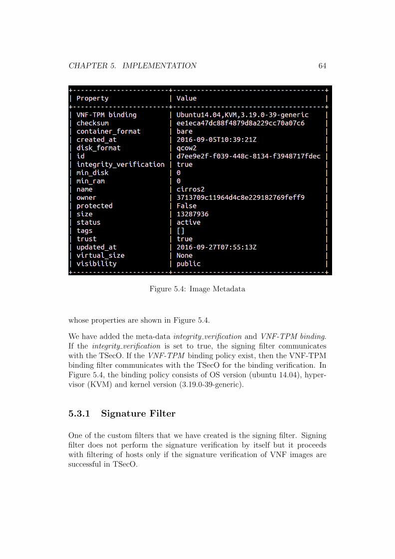
CHAPTER 5. IMPLEMENTATION 64
Figure 5.4: Image Metadata
whose properties are shown in Figure 5.4.
We have added the meta-data integrity verification and VNF-TPM binding.If the integrity verification is set to true, the signing filter communicateswith the TSecO. If the VNF-TPM binding policy exist, then the VNF-TPMbinding filter communicates with the TSecO for the binding verification. InFigure 5.4, the binding policy consists of OS version (ubuntu 14.04), hyper-visor (KVM) and kernel version (3.19.0-39-generic).
5.3.1 Signature Filter
One of the custom filters that we have created is the signing filter. Signingfilter does not perform the signature verification by itself but it proceedswith filtering of hosts only if the signature verification of VNF images aresuccessful in TSecO.
CHAPTER 5. IMPLEMENTATION 65
The filter extracts the ID and hostname from the filter properties andhost state. In order to verify the image signature, we also take the SHA256of the image file. This data is sent to the TSecO in the form of JSON.
Example of JSON input is as follows:
{"ID":"43f24f28-faba-4232-8fa8-86322a3536d8","Image hash":"34987d0d5702f8813f3ff9efe90e9e39e
6926ec78658763580a79face67f3394"}
This is sent to the TSecO using Python requests. We use the endpoints/checkSignature in TSecO, to verify the signing.
checksig = requests.get("http://x.x.x.x:8081/checkSignature",
data=json, headers=’Content-type’: ’application/json’)
The host passes() of the filter returns a True/False based on the responsefrom TSecO.
5.3.2 VNF-TPM Binding Filter
We introduced the VNF-TPM binding filter in the OpenStack’s filter sched-uler, which is also a custom filter that selects hosts based on the VNF-TPMbinding requirements.
This filter extracts the hostname and Image identifier from the filter proper-ties.
{"hostname":"controller","ID":"43f24f28-faba-4232-8fa8-86322a3536d8"}
This data is sent to TSecO using python get request to the /checkVMTPM
API end point.
vmtpm = requests.get("http://x.x.x.x:8081/checkVMTPM", data=json,
headers={’Content-type’: ’application/json’})
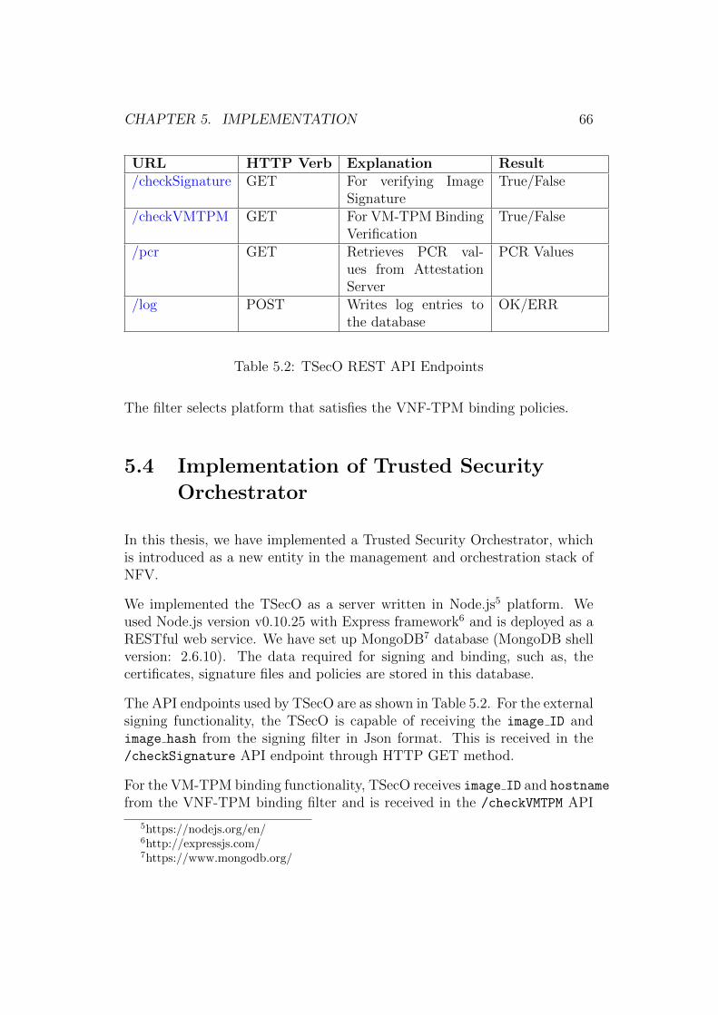
CHAPTER 5. IMPLEMENTATION 66
URL HTTP Verb Explanation Result/checkSignature GET For verifying Image
SignatureTrue/False
/checkVMTPM GET For VM-TPM BindingVerification
True/False
/pcr GET Retrieves PCR val-ues from AttestationServer
PCR Values
/log POST Writes log entries tothe database
OK/ERR
Table 5.2: TSecO REST API Endpoints
The filter selects platform that satisfies the VNF-TPM binding policies.
5.4 Implementation of Trusted Security
Orchestrator
In this thesis, we have implemented a Trusted Security Orchestrator, whichis introduced as a new entity in the management and orchestration stack ofNFV.
We implemented the TSecO as a server written in Node.js5 platform. Weused Node.js version v0.10.25 with Express framework6 and is deployed as aRESTful web service. We have set up MongoDB7 database (MongoDB shellversion: 2.6.10). The data required for signing and binding, such as, thecertificates, signature files and policies are stored in this database.
The API endpoints used by TSecO are as shown in Table 5.2. For the externalsigning functionality, the TSecO is capable of receiving the image ID andimage hash from the signing filter in Json format. This is received in the/checkSignature API endpoint through HTTP GET method.
For the VM-TPM binding functionality, TSecO receives image ID and hostname
from the VNF-TPM binding filter and is received in the /checkVMTPM API
5https://nodejs.org/en/6http://expressjs.com/7https://www.mongodb.org/
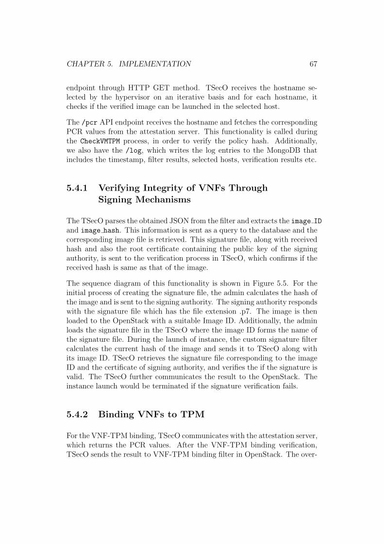
CHAPTER 5. IMPLEMENTATION 67
endpoint through HTTP GET method. TSecO receives the hostname se-lected by the hypervisor on an iterative basis and for each hostname, itchecks if the verified image can be launched in the selected host.
The /pcr API endpoint receives the hostname and fetches the correspondingPCR values from the attestation server. This functionality is called duringthe CheckVMTPM process, in order to verify the policy hash. Additionally,we also have the /log, which writes the log entries to the MongoDB thatincludes the timestamp, filter results, selected hosts, verification results etc.
5.4.1 Verifying Integrity of VNFs ThroughSigning Mechanisms
The TSecO parses the obtained JSON from the filter and extracts the image ID
and image hash. This information is sent as a query to the database and thecorresponding image file is retrieved. This signature file, along with receivedhash and also the root certificate containing the public key of the signingauthority, is sent to the verification process in TSecO, which confirms if thereceived hash is same as that of the image.
The sequence diagram of this functionality is shown in Figure 5.5. For theinitial process of creating the signature file, the admin calculates the hash ofthe image and is sent to the signing authority. The signing authority respondswith the signature file which has the file extension .p7. The image is thenloaded to the OpenStack with a suitable Image ID. Additionally, the adminloads the signature file in the TSecO where the image ID forms the name ofthe signature file. During the launch of instance, the custom signature filtercalculates the current hash of the image and sends it to TSecO along withits image ID. TSecO retrieves the signature file corresponding to the imageID and the certificate of signing authority, and verifies the if the signature isvalid. The TSecO further communicates the result to the OpenStack. Theinstance launch would be terminated if the signature verification fails.
5.4.2 Binding VNFs to TPM
For the VNF-TPM binding, TSecO communicates with the attestation server,which returns the PCR values. After the VNF-TPM binding verification,TSecO sends the result to VNF-TPM binding filter in OpenStack. The over-

CHAPTER 5. IMPLEMENTATION 68
Figure 5.5: Sequence Diagram of Signing Process
CHAPTER 5. IMPLEMENTATION 69
Figure 5.6: VNF-TPM Binding Process
all implementation sequence is as shown in Figure 5.6.
Binding the VNFs to the TPM is performed based on a set of polices definedin the Trusted Security Orchestrator. A Policy is a 3-tuple entry consistingof the tuple (Image ID, Policy, Hash).
Image ID: This field corresponds to the Image ID of the image. This can bea 32 bit string used to identify an image.
Policy: The policy is an array consisting of the PCR registers that forms thepolicy. For example, policy [0,18] specifies the need for BIOS and hypervisorto be trusted.
Hash: Hash has the SHA256 value of the PCR values of the Registers in thepolicy list.
For each entry in the policy array, the corresponding PCR value from the(Register, PCR value) pair list is taken. We then calculate the SHA256of the sum of PCR Values of the given policy list. Further, we compare the
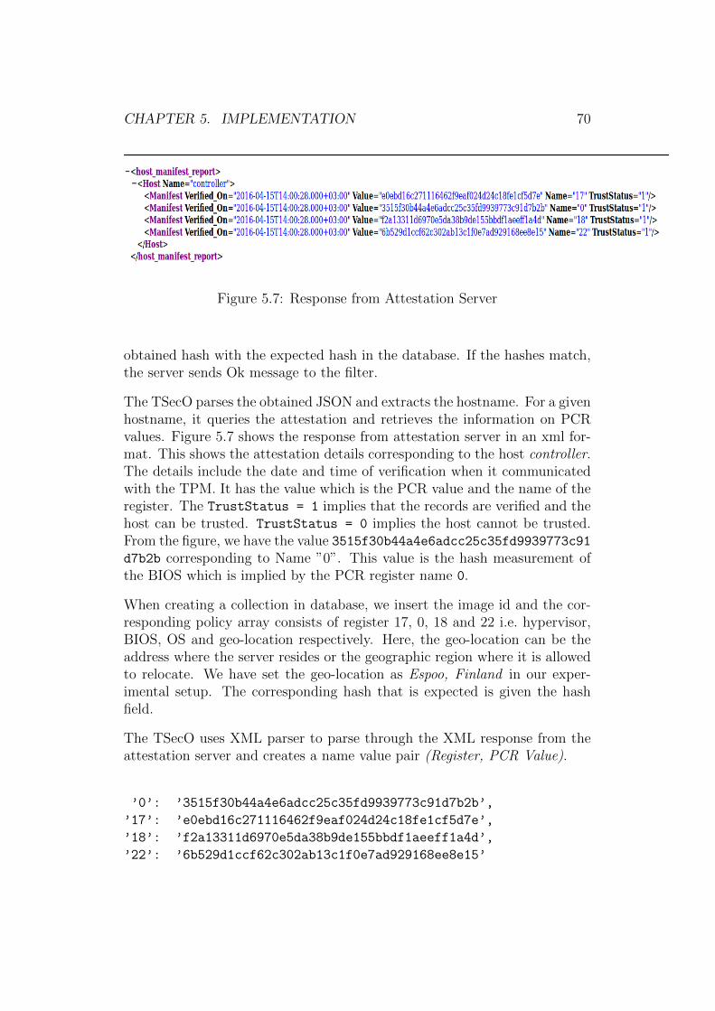
CHAPTER 5. IMPLEMENTATION 70
Figure 5.7: Response from Attestation Server
obtained hash with the expected hash in the database. If the hashes match,the server sends Ok message to the filter.
The TSecO parses the obtained JSON and extracts the hostname. For a givenhostname, it queries the attestation and retrieves the information on PCRvalues. Figure 5.7 shows the response from attestation server in an xml for-mat. This shows the attestation details corresponding to the host controller.The details include the date and time of verification when it communicatedwith the TPM. It has the value which is the PCR value and the name of theregister. The TrustStatus = 1 implies that the records are verified and thehost can be trusted. TrustStatus = 0 implies the host cannot be trusted.From the figure, we have the value 3515f30b44a4e6adcc25c35fd9939773c91d7b2b corresponding to Name ”0”. This value is the hash measurement ofthe BIOS which is implied by the PCR register name 0.
When creating a collection in database, we insert the image id and the cor-responding policy array consists of register 17, 0, 18 and 22 i.e. hypervisor,BIOS, OS and geo-location respectively. Here, the geo-location can be theaddress where the server resides or the geographic region where it is allowedto relocate. We have set the geo-location as Espoo, Finland in our exper-imental setup. The corresponding hash that is expected is given the hashfield.
The TSecO uses XML parser to parse through the XML response from theattestation server and creates a name value pair (Register, PCR Value).
’0’: ’3515f30b44a4e6adcc25c35fd9939773c91d7b2b’,
’17’: ’e0ebd16c271116462f9eaf024d24c18fe1cf5d7e’,
’18’: ’f2a13311d6970e5da38b9de155bbdf1aeeff1a4d’,
’22’: ’6b529d1ccf62c302ab13c1f0e7ad929168ee8e15’
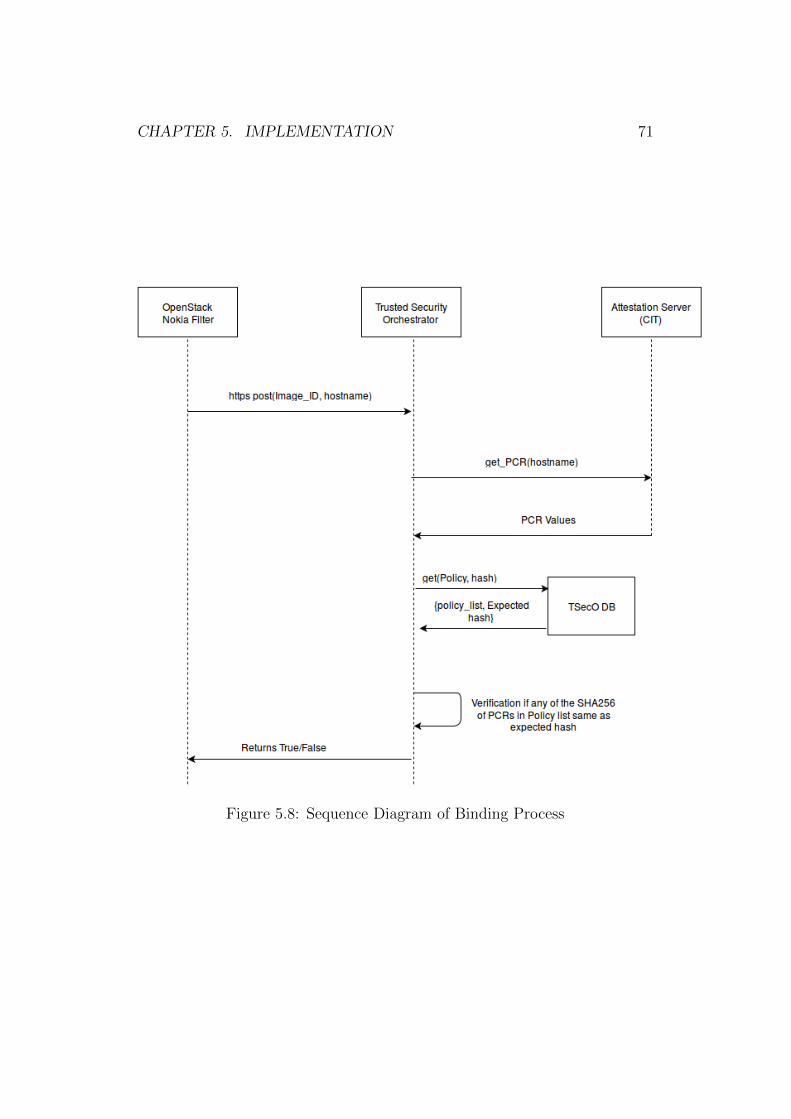
CHAPTER 5. IMPLEMENTATION 71
Figure 5.8: Sequence Diagram of Binding Process
CHAPTER 5. IMPLEMENTATION 72
The checkvmtpm module in the TSecO server receives this (name,value)
pair. Further, it makes connection to the database.
The module retrieves the policy list and the expected hash from the database.For each entry in the policy array, the corresponding value from the (name,
value) pair is taken. We then calculate the SHA256 of the entire value listand compare with the expected hash in the database. If the hashes match,the TSecO sends Ok message to the VNF-TPM binding filter indicating asuccess as shown in Figure 5.8.
5.5 Performance Evaluation of Signing and
VNF-TPM binding
We evaluate the performance of signing and VNF-TPM binding mechanismsbased on the time taken for OpenStack filters to perform resource selection.This includes the time to send the image metadata to TSecO, time taken byTSecO to verify the signing and binding, and also the time at which filtersreceive the result from TSecO. Further, we evaluate the correlation betweenthe size of image and the total time taken to select a host.
As discussed before the RAM filter and compute filter are standard Open-Stack filters. The trust assertion filter is a third party filter by Intel whichis used to select trusted hosts. The signing and VNF-TPM binding are thecustom filters which we have developed.
The time taken for the filters : RAM filter, compute filter, trust assertionfilter, signing filter and the VNF-TPM binding filter to execute are repre-sented as a box plot in Figure 5.9. This data is collected after a launch of20 instances where the signing and binding was successful and the instanceswere launched in a trusted host. The hardware specifications of the trustedhosts have been explained in Section 5.1.
The mean execution time taken for RAM and compute filters are approxi-mately around 0.0014 seconds. Whereas, the signing and VNF-TPM BindingFilter takes 0.14sec and 0.12sec respectively. As mentioned before, this in-cludes the time taken for both these filters to communicate with TSecO andretrieve the result. The filter that takes fairly long time to execute is theIntel’s Trust Assertion Filter with the mean time of 7.4 seconds. This is a
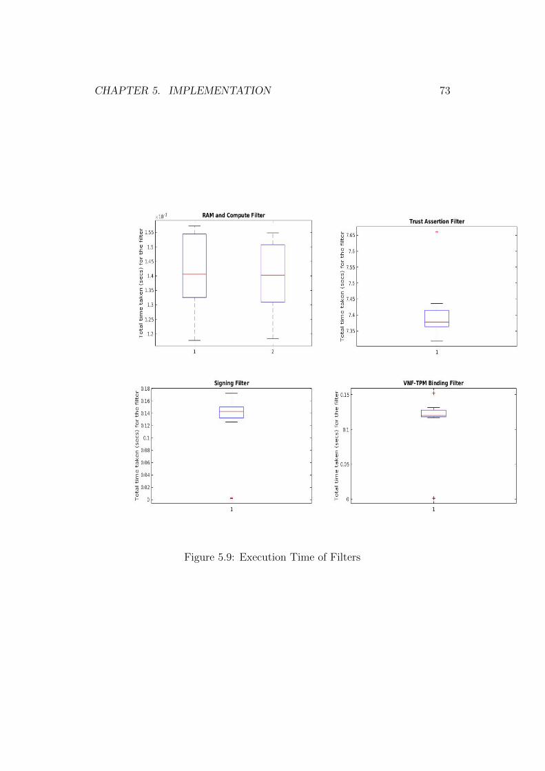
CHAPTER 5. IMPLEMENTATION 73
Figure 5.9: Execution Time of Filters
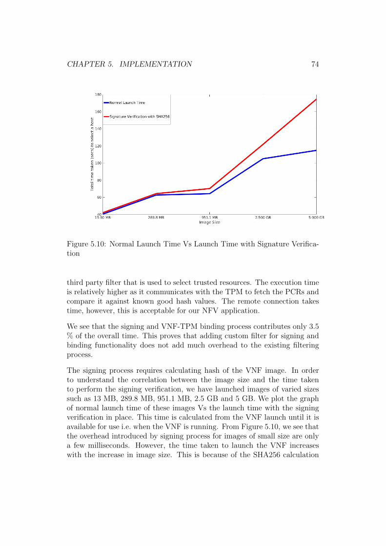
CHAPTER 5. IMPLEMENTATION 74
Figure 5.10: Normal Launch Time Vs Launch Time with Signature Verifica-tion
third party filter that is used to select trusted resources. The execution timeis relatively higher as it communicates with the TPM to fetch the PCRs andcompare it against known good hash values. The remote connection takestime, however, this is acceptable for our NFV application.
We see that the signing and VNF-TPM binding process contributes only 3.5% of the overall time. This proves that adding custom filter for signing andbinding functionality does not add much overhead to the existing filteringprocess.
The signing process requires calculating hash of the VNF image. In orderto understand the correlation between the image size and the time takento perform the signing verification, we have launched images of varied sizessuch as 13 MB, 289.8 MB, 951.1 MB, 2.5 GB and 5 GB. We plot the graphof normal launch time of these images Vs the launch time with the signingverification in place. This time is calculated from the VNF launch until it isavailable for use i.e. when the VNF is running. From Figure 5.10, we see thatthe overhead introduced by signing process for images of small size are onlya few milliseconds. However, the time taken to launch the VNF increaseswith the increase in image size. This is because of the SHA256 calculation
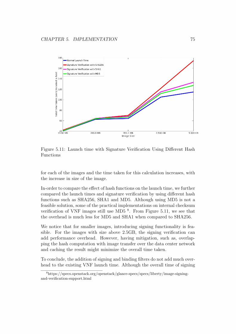
CHAPTER 5. IMPLEMENTATION 75
Figure 5.11: Launch time with Signature Verification Using Different HashFunctions
for each of the images and the time taken for this calculation increases, withthe increase in size of the image.
In-order to compare the effect of hash functions on the launch time, we furthercompared the launch times and signature verification by using different hashfunctions such as SHA256, SHA1 and MD5. Although using MD5 is not afeasible solution, some of the practical implementations on internal checksumverification of VNF images still use MD5 8. From Figure 5.11, we see thatthe overhead is much less for MD5 and SHA1 when compared to SHA256.
We notice that for smaller images, introducing signing functionality is fea-sible. For the images with size above 2.5GB, the signing verification canadd performance overhead. However, having mitigation, such as, overlap-ping the hash computation with image transfer over the data center networkand caching the result might minimize the overall time taken.
To conclude, the addition of signing and binding filters do not add much over-head to the existing VNF launch time. Although the overall time of signing
8https://specs.openstack.org/openstack/glance-specs/specs/liberty/image-signing-and-verification-support.html
CHAPTER 5. IMPLEMENTATION 76
functionality increases with the increase in image size, it can be addressedwith certain mitigations in place.
5.6 Summary
In this Chapter, we have looked into the method of implementation of thesigning and the VNF-TPM binding. Further, we have also performed anevaluation to show that these methods do not add much overhead to theresource selection process.
Chapter 6
Discussion
In Chapter 3, we have listed the requirements for enabling trust in a telcocloud environment. In this chapter, we discuss how our approach meets theserequirements and detail some of our future works.
The first requirement is the NFVI trust. In this thesis, we have constructeda trusted telco cloud using the existing trusted computing technologies thatleverages the use of TPM. Using trusted computing platforms for cloud-basedenvironments ensure the integrity of critical software components such asBIOS, OS and hypervisor. Further, storing the cryptographic measurementsof these components in TPM chip reduces the possibility of software-basedattacks. Building a trusted cloud guarantees the NFVI trust during the boottime and also ensures that the integrity of the platform is preserved. Whilethis satisfies the requirement of boot time trust, we must note that these arethe static measurements taken by the TPM during the boot time of a system.In a cloud environment, the servers may not be rebooted on a continual basisand in most cases, the TPM contains the old measurement values which weretaken during the boot time. Hence, it is important to invent methods toperform the run time attestation of software components in-order to preserveits integrity during the run time. While there are methods to perform runtime verification, such as, Intel TXT, currently we are not aware of techniquesthat can perform run time attestation which will be a part of our future work.
The next requirement is to meet the Quality of Service of VNFs. Meetingthe QoS of VNFs requires less failure and the VNF needs to be launchedwhen it is requested without any latency. In order to meet this requirement,we proposed a policy-based fault tolerance approach. Each policy consists of
77
CHAPTER 6. DISCUSSION 78
a list of software components such as BIOS and OS whose integrity needs tobe preserved. In our scenario even if the integrity of all components are notverified, it might be possible to launch the VNF with minimal policy but withcertain mitigations in place. This preserve the SLAs and reduce the failuresduring launch of VNFs. We also proposed methods to define policy strengththat are based on weighing and the length of policies. However, definingpolicy strength is crucial and a difficult problem. To our knowledge, thereare no existing works that deal with policy-based fault tolerance approach forresource management. We strongly believe that such an approach is essentialfor a telco cloud environment where the primary goal is to preserve the SLAsand maintain QoS. Defining the policy strength as well as implementing apolicy-based fault tolerance approach will be a part of our future work.
Another requirement is to consider the integrity verification of VNFs duringthe launch time. In this thesis, we developed TSecO, an external manage-ment entity capable of performing the VNF integrity checks. We developeda signing mechanism where the signing authority signs the hash of the VNFimage and stores this signature file along with its root certificate in TSecO.During the VNF launch time, the hypervisor sends the VNF identifier andhash of the image to TSecO who verifies the integrity. For the proof of con-cept we implemented this signing functionality in TSecO and the requestfor signature verification is sent by one of the custom filters in OpenStack.This further led to the development of VNF-TPM binding process. In caseof a telco cloud environment the service providers want to have certain plat-form specifications in order to launch the VNFs and the VNF-TPM bindingmethod achieves this. We devised a policy-based mapping of VNF imagesto the platform configurations. We implemented the VNF-TPM bindingmethod in TSecO where we select the host based on policy-based criteria as-sociated with the VNF. Further, we did the performance evaluation of boththe signing and the binding methods, and showed that it does not add muchoverhead to the existing provisioning of VNFs.
In the existing works, VNF integrity checks are performed in hypervisor itselfand do not take insider attackers into consideration. Performing the signingoperation by TSecO prevents unauthorized modification by insider attackersand also keeps a log of the hypervisor requests. Also, to our knowledge thereare no existing works on policy-based VNF-TPM binding. This method isanother way to ensure QoS service to the VNFs by guaranteeing the platformconfiguration where it is placed. We see that both the signing and bindingmethods are essential for a telco cloud environment.
CHAPTER 6. DISCUSSION 79
We can also associate the requirement of maintaining QoS of VNFs to theresource selection problem in NFV. This is because the question here is toselect a NFVI where the VNFs can be instantiated based on certain criteriaof VNF. In a trusted telco cloud the criteria is to find a trusted host wherethese VNFs can be instantiated. In this thesis, we used an attestation servicethat communicates with the TPM and helps us verify the trust level of theplatform. As a proof of concept, we used trusted filters and custom filters inOpenStack that help us select host that satisfy the requirements of the VNFbeing launched.
We noticed that by solving the challenges of incorporating trust in NFV, thethesis moved its focus to a much bigger problem of resource management.This is because identifying a resource that satisfies all the requirements ofVNFs and narrowing the possibility of selecting a resource might lead to asituation of not finding a suitable host. However, having a policy-based faulttolerance along with methods of signing and binding of the VNFs, we see thatour work has the potential to solve the resource management problem. TheVNF integrity and its placement can be verified with the help of signing andbinding methods. If the current policies do not satisfy these requirements,we can use the policy-based fault tolerance approach where we can launchthe VNF with minimal policy but with mitigations. This ensures that theVNFs are launched irrespective of the availability of resources, yet preservingthe SLAs and satisfying the requirements for launching the VNFs. While animplementation of policy strength and mitigation mechanisms are missing inthis thesis, we are not aware of any existing works that deal with policy-basedfault tolerance for resource selection.
The last requirement we considered was to have an external entity to au-dit the actions of NFVI. In our development setup the TSecO performs thelogging operations. It logs the time of request, VNF identifier, host selec-tion, VNF integrity verification result, VNF binding verification result etc.TSecO acts as a management entity which communicates with the signingauthority, attestation service and other MANO components. The operationperformed by TSecO is critical and hence we cannot perform the same insidethe hypervisor. An external logging is always beneficial to understand thefailure scenarios in NFVI.
We have satisfied the requirements which we had specified in Chapter 3.However, our techniques have its own limitations. While VNF integrity veri-fication through signing and the VNF-TPM binding mechanism address cer-tain challenges, both these methods are depended on their communication
CHAPTER 6. DISCUSSION 80
with the TSecO. If an attacker gains admin privilege in the hypervisor, itis possible to launch a malicious instance by modifying the filter scheduler,even if the TSecO returns a failure. However, it is very well possible to detectthis using the log entries in TSecO. Placing the TSecO and its managementfunction separated from the NFVI helps in detecting any malicious actions.Also, the service provider can communicate with TSecO and check the auditsduring every launch of VNF to verify the entire launch process. It might bestill possible for the attacker with admin privileges to inject malware afterthe signature verification. Hence, our method does not completely preventthe system from such an attack.
Consider the trust chain we discussed in Section 4.7. In our architecture,the service provider can communicate with the TSecO, which is a trustedentity to acquire the platform specific information. One of the limitationshere is the inability of the service provider to directly communicate with theattestation server. The direct communication between service provider andattestation server is one of the main goals of attestation and this architecturefails to provide that. This is because such a feature is not yet available in thecurrent OpenStack and Intel’s attestation service, because their architectureaims to hide the technical details of attestation from the service provider.Also, we noticed that service provider has to place trust in the infrastructureprovider. While the level of trust can be limited with the presence of TSecOand audit logs, yet we cannot completely break this part of the trust chain.Also in our trust chain, the service provider has a transitive trust relationshipthrough the TSecO. If the trust chain between the service provider and theTSecO is broken, then the service provider cannot trust the signing authorityand the attestation service. We see that the longer the trust chain, the morefragile is the architecture.
To summarize, this thesis provides an overview of the challenges in incorpo-rating trust in NFV and devises techniques to address these challenges. Weconstructed a trusted telco cloud to address the issue of platform trust. Wehave invented methods such as VNF signing and VNF-TPM binding, whichaims to ensure the VNF integrity and proper placement of VNFs. We lookedinto the aspects of resource management and meeting the QoS requirementsof VNF. We also proposed a policy based fault tolerance mechanism, whichalong the VNF integrity is a way to handle resource management problems.We showed that our work satisfies all the requirements that we have specifiedin Chapter 3. We also discussed the limitations of our work which opens upnew research directions for enhancing the trust in telco cloud.
Chapter 7
Conclusions
In this thesis, we have looked into various aspects of incorporating trust in aNetwork Function Virtualization. The discussions focused on the scenariosof telco cloud, which involves mission critical components. We looked intothe challenges of incorporating trust in NFV such as platform trust, VNFintegrity and fault tolerance. Further, we have devised techniques to addressthese challenges.
The first challenge which we identified is to provide platform trust duringthe boot time of NFVI. We used the existing trusted computing technologiesto achieve this. We have constructed a trusted telco cloud, which uses TPMto store the cryptographic measurements of various software componentssuch as BIOS, OS and hypervisor. Using hardware-based solutions to enableplatform trust, helps in detection of unauthorized modification and reducesthe possibility of attacks. We have also included the attestation service inour architecture that verifies the platform trust remotely.
Further, the thesis introduces a new management entity to the managementand orchestration stack of NFV, which is the Trusted Security Orchestrator(TSecO). The main functionality of TSecO is to verify the VNF integrityand to bind VNF to specific NFVI, which are the next set of challenges weidentified. One of the contributions of this thesis is the implementation ofthe TSecO itself. Apart from communicating with the attestation server andsigning authority, TSecO performs critical functionalities such as verifyingsignatures, checking the binding policies, logging the hypervisor requests andcommunicating the result back to hypervisor. Additionally, TSecO can alsocommunicate with other MANO components in NFV.
81
CHAPTER 7. CONCLUSIONS 82
During the startup of a VNF, an image is selected by the hypervisor, whoseintegrity needs to be verified before launching it. We have discussed theneed for this VNF integrity verification and devised techniques to addressthe same. We designed and implemented an external signing functionalityin TSecO, that can verify the integrity of VNFs during the launch time.This method detects if the VNF images are tampered, proves the owner-ship of VNFs and also protects them from internal attackers. Hence, thisfunctionality is better than the existing internal signing features. We alsoobserved that telco cloud demand certain specifications on the platform be-fore launching the VNF. We focused on methods to bind VNFs to certainplatform configurations. We have designed and implemented a VNF-TPMbinding mechanism in TSecO where we associated VNFs to PCR values ofthe hosts. This mechanism helps in determining if platform configurationssatisfy the requirements of VNFs to be launched. Further, the performanceof signing and VNF-TPM binding methods are evaluated to show that it doesnot add much overhead to the existing resource selection by the hypervisor.
Another challenge of incorporating trust in NFV is meeting the QoS of VNFs.Meeting the QoS of VNFs involves launching them without failure. Theoccurrence of failure seems to be rapid in cases where the NFVI does nothave any trusted resources. To solve this resource management problem, weproposed a policy based fault tolerance approach. In our approach, we definepolicies necessary to launch a VNF by considering the scenarios for a failure.Here, we discussed the challenges of constructing policies as well as definingthe strongest policy. Having a policy based approach helps in launching theVNFs with best possible policy, while also maintaining the SLAs at the sametime. Moreover, in scenarios where the strongest policy fails, this methodallows the VNFs to be launched with less strong policy, but with certainmitigations in place.
We believe that the proposed fault tolerance method along with the VNFintegrity mechanisms, have the potential to handle the resource managementproblems in trusted NFV.
Bibliography
[1] TPM Architecture Specification (Version 2.0). Trusted ComputingGroup. http://www.trustedcomputinggroup.org/wp-content/uploads/
TPM-Rev-2.0-Part-1-Architecture-01.16.pdf.
[2] TCG Specification Architecture Overview. vol. 1, Trusted ComputingGroup, TCG Specification Revision, pp. 1–24.
[3] Technical Aspects of Lawful Interception. In ITU-T Technology WatchReport (May 2008), International Telecommunication Union, Telecom-munication Standardization Policy Division, ITU TelecommunicationStandardization Sector.
[4] Network Functions Virtualization: An introduction, benefits, enablers,challenges and call for action. In SDN and OpenFlow World Congress(October 2012), ETSI.
[5] Network functions virtualisation (NFV); architectural framework. ETSIGroup Specification ETSI GS NFV 002 V1.1.1 (2013-10), 2013.
[6] Network Functions Virtualization; NFV Security; Security and TrustGuidance. In Report ETSI GS NFV-SEC 003 (V1. 1.1) (December2014), ETSI, NFVISG.
[7] Intel Cloud Integrity Technology Product Guide, Revision 2.0. In-tel, April 2015. http://download.intel.com/support/sftw/ds/cit/sb/
trust_attestation_server_2_0_product_guidev2.pdf.
[8] Abbadi, I. M., and Alawneh, M. A framework for establishing trustin the cloud. In Computers & Electrical Engineering (2012), vol. 38,Elsevier, pp. 1073–1087.
[9] Achemlal, M., Gharou, S., and Gaber, C. Trusted platformmodule as an enabler for security in cloud computing. In Network and
83
BIBLIOGRAPHY 84
Information Systems Security (SAR-SSI), 2011 Conference on (2011),IEEE, pp. 1–6.
[10] Armbrust, M., Fox, A., Griffith, R., Joseph, A. D., Katz, R.,Konwinski, A., Lee, G., Patterson, D., Rabkin, A., Stoica,I., et al. A view of cloud computing. Communications of the ACM53, 4 (2010), 50–58.
[11] Buvat, J., and Nandan, P. Cloud computing: The telco opportu-nity. Telecom, Media & Entertainment, Telecom and Media Insights, 57(2010).
[12] Chow, R., Golle, P., Jakobsson, M., Shi, E., Staddon, J.,Masuoka, R., and Molina, J. Controlling data in the cloud: Out-sourcing computation without outsourcing control. In Proceedings of the2009 ACM Workshop on Cloud Computing Security (2009), CCSW ’09,ACM, pp. 85–90.
[13] Davne, J., Volkov, A., Yankelevich, M., and Malamud, M.Managing services in a cloud computing environment, Dec. 9 2014. USPatent 8,910,278.
[14] Dawoud, W., Takouna, I., and Meinel, C. Infrastructure as aservice security: Challenges and solutions. In the 7th International Con-ference on Informatics and Systems (INFOS) (2010), IEEE ComputerSociety.
[15] Descher, M., Masser, P., Feilhauer, T., Tjoa, A. M., andHuemer, D. Retaining data control to the client in infrastructureclouds. In International Conference on Availability, Reliability and Se-curity ARES’09. (2009), IEEE, pp. 9–16.
[16] Dillon, T., Wu, C., and Chang, E. Cloud computing: issuesand challenges. In Advanced Information Networking and Applications(AINA), 2010 24th IEEE International Conference on (2010), IEEE,pp. 27–33.
[17] Dobson, J., and Randell, B. Building reliable secure computingsystems out of unreliable insecure components. In In Proceedings ofthe Conference on Security and Privacy, Oakland, USA (1986), IEEE,pp. 187–193.
[18] Dodig-Crnkovic, G. Scientific methods in computer science. InProceedings of the Conference for the Promotion of Research in IT at
BIBLIOGRAPHY 85
New Universities and at University Colleges in Sweden, Skovde, Suecia(2002), pp. 126–130.
[19] Fernandes, D. A., Soares, L. F., Gomes, J. V., Freire, M. M.,and Inacio, P. R. Security issues in cloud environments: a survey. InInternational Journal of Information Security (2014), vol. 13, Springer,pp. 113–170.
[20] Gabrielsson, J., Hubertsson, O., Mas, I., and Skog, R. Cloudcomputing in telecommunications. Ericsson Review 1 (2010), 29–33.
[21] Gonzalez, N., Miers, C., Redigolo, F., Carvalho, T., Sim-plicio, M., Naslund, M., and Pourzandi, M. A QuantitativeAnalysis of Current Security Concerns and Solutions for Cloud Comput-ing. In Proceedings of the 2011 IEEE Third International Conferenceon Cloud Computing Technology and Science (2011), IEEE ComputerSociety, pp. 231–238.
[22] Greene, J. Intel trusted execution technology. Intel TechnologyWhitepaper (2012).
[23] Han, B., Gopalakrishnan, V., Ji, L., and Lee, S. Network func-tion virtualization: Challenges and opportunities for innovations. Com-munications Magazine, IEEE 53, 2 (2015), 90–97.
[24] Hoban, A., Czesnowicz, P., Mooney, S., Chapman, J., Shaula,I., Kinsella, R., and Buerger, C. A Path to Line-Rate-CapableNFV Deployments with Intel Architecture and the OpenStack Juno Re-lease. Intel Corporation, March 2015.
[25] Huang, D., Zhang, X., Kang, M., and Luo, J. Mobicloud: build-ing secure cloud framework for mobile computing and communication.In Service Oriented System Engineering (SOSE), 2010 Fifth IEEE In-ternational Symposium on (2010), IEEE, pp. 27–34.
[26] Jayaram, K., Safford, D., Sharma, U., Naik, V., Pendarakis,D., and Tao, S. Trustworthy geographically fenced hybrid clouds.In Proceedings of the 15th international middleware conference (2014),ACM, pp. 37–48.
[27] Khan, K. M., and Malluhi, Q. Establishing trust in cloud comput-ing. In IT professional (2010), vol. 12, IEEE, pp. 20–27.
BIBLIOGRAPHY 86
[28] Ko, R. K., Jagadpramana, P., Mowbray, M., Pearson, S.,Kirchberg, M., Liang, Q., and Lee, B. S. TrustCloud: A frame-work for accountability and trust in cloud computing. In 2011 IEEEWorld Congress on Services (2011), IEEE, pp. 584–588.
[29] Krautheim, F. J., Phatak, D. S., and Sherman, A. T. Intro-ducing the trusted virtual environment module: a new mechanism forrooting trust in cloud computing. In International Conference on Trustand Trustworthy Computing (2010), Springer, pp. 211–227.
[30] Lemke, A. Why service providers need an NFV platform: StrategicWhite Paper. Alcatel Lucent, January 2015.
[31] Lie, D., Cohen, R., and Reiner, R. System and method for securecloud computing, July 14 2015. US Patent 9,081,989.
[32] Masutani, H., Nakajima, Y., Kinoshita, T., Hibi, T., Taka-hashi, H., Obana, K., Shimano, K., and Fukui, M. Require-ments and design of flexible nfv network infrastructure node leveragingsdn/openflow. In Optical Network Design and Modeling, 2014 Interna-tional Conference on (2014), IEEE, pp. 258–263.
[33] McCune, J. M. Reducing the trusted computing base for applicationson commodity systems. ProQuest, 2009.
[34] Mell, P., and Grance, T. The NIST Definition of Cloud Computing.National Institute of Standards and Technology Gaithersburg, 2011.
[35] Membrey, P., Chan, K. C., Ngo, C., Demchenko, Y., andDe Laat, C. Trusted virtual infrastructure bootstrapping for on de-mand services. In Availability, Reliability and Security (ARES), 2012Seventh International Conference on (2012), IEEE, pp. 350–357.
[36] Mijumbi, R., Serrat, J., Gorricho, J.-L., Latre, S., Char-alambides, M., and Lopez, D. Management and orchestration chal-lenges in network functions virtualization. Communications Magazine,IEEE 54, 1 (2016), 98–105.
[37] Neisse, R., Holling, D., and Pretschner, A. Implementing trustin cloud infrastructures. In Proceedings of the 2011 11th IEEE/ACM In-ternational Symposium on Cluster, Cloud and Grid Computing (2011),IEEE Computer Society, pp. 524–533.
BIBLIOGRAPHY 87
[38] Ngo, C., Membrey, P., Demchenko, Y., and De Laat, C. Se-curity framework for virtualised infrastructure services provisioned on-demand. In Cloud Computing Technology and Science (CloudCom),2011 IEEE Third International Conference on (2011), IEEE, pp. 698–704.
[39] Perez, R., Sailer, R., van Doorn, L., et al. vTPM: Virtualizingthe trusted platform module. In Proc. 15th Conf. on USENIX SecuritySymposium (2006), pp. 305–320.
[40] Pitt, D. Trust in the cloud: the role of SDN. In Network Security(2013), vol. 2013, Elsevier, pp. 5–6.
[41] Rocha, F., and Correia, M. Lucy in the sky without diamonds:Stealing confidential data in the cloud. In Dependable Systems and Net-works Workshops (DSN-W), 2011 IEEE/IFIP 41st International Con-ference on (2011), IEEE, pp. 129–134.
[42] Sadeghi, A.-R., Stuble, C., and Winandy, M. Property-basedTPM virtualization. In International conference on Information Security(2008), Springer, pp. 1–16.
[43] Santos, N., Gummadi, K. P., and Rodrigues, R. Towards trustedcloud computing. In Proceedings of the 2009 Conference on Hot Topicsin Cloud Computing (Berkeley, CA, USA, 2009), HotCloud’09, USENIXAssociation.
[44] Scarlata, V., Rozas, C., Wiseman, M., Grawrock, D., andVishik, C. TPM Virtualization: Building a general framework. InTrusted Computing. Springer, 2008, pp. 43–56.
[45] Schiffman, J., Moyer, T., Vijayakumar, H., Jaeger, T., andMcDaniel, P. Seeding clouds with trust anchors. In Proceedings ofthe 2010 ACM workshop on Cloud computing security workshop (2010),ACM, pp. 43–46.
[46] Stumpf, F., Benz, M., Hermanowski, M., and Eckert, C. Anapproach to a trustworthy system architecture using virtualization. InInternational Conference on Autonomic and Trusted Computing (2007),Springer, pp. 191–202.
[47] Subramanya, S., and Yi, B. K. Digital rights management. IEEEPotentials 25, 2 (2006), 31–34.
BIBLIOGRAPHY 88
[48] Takabi, H., Joshi, J. B., and Ahn, G.-J. Securecloud: Towardsa comprehensive security framework for cloud computing environments.In Computer Software and Applications Conference Workshops (COMP-SACW), 2010 IEEE 34th Annual (2010), IEEE, pp. 393–398.
[49] Yan, Z., and Holtmanns, S. Trust modeling and management: fromsocial trust to digital trust. IGI Global (2008), 290–323.
[50] Yan, Z., Zhang, P., and Vasilakos, A. V. A security and trustframework for virtualized networks and software-defined networking. Wi-ley Online Library, 2015.
[51] Yang, W., and Fung, C. A survey on security in network functionsvirtualization. In 2016 IEEE NetSoft Conference and Workshops (2016),IEEE, pp. 15–19.
[52] Zhang, F., Chen, J., Chen, H., and Zang, B. CloudVisor:Retrofitting protection of virtual machines in multi-tenant cloud withnested virtualization. In Proceedings of the Twenty-Third ACM Sympo-sium on Operating Systems Principles (2011), ACM, pp. 203–216.
[53] Zhang, Q., Cheng, L., and Boutaba, R. Cloud computing: state-of-the-art and research challenges. Journal of internet services and ap-plications 1, 1 (2010), 7–18.
[54] Zhang, X., and Seifert, J.-P. Method and system for enforcingtrusted computing policies in a hypervisor security module architecture,July 10 2012. US Patent 8,220,029.
Appendix A
A.1 Enabling tboot
1. Enable and activate Current TPM State in the TCG Configuration tabof BIOS.
2. Enable Intel TXT, SMX and VMX in BIOS.
3. Use any linux distribution as the host OS. Here, we use Ubuntu 14.04LTS.
4. Install tboot, trousers and tpm packages.$ sudo apt-get install tboot tpm-tools trousers
5. Check if tpm is present in the path /dev/tpm0
6. Update the grub boot loadergrub-mkconfig ?o /boot/grub/grub.cfg
7. Reboot and select the tboot option
8. After reboot check the txt stat and PCR values as shown in the Figure5.2.
89
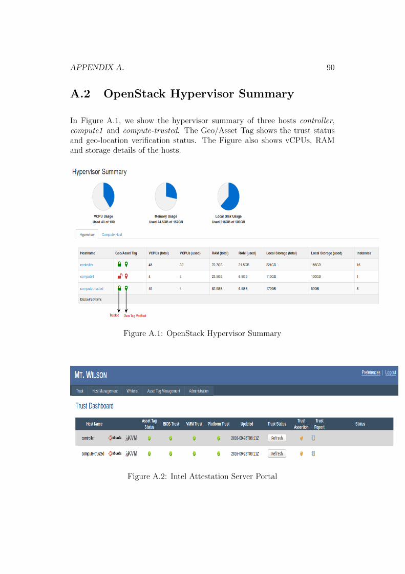
APPENDIX A. 90
A.2 OpenStack Hypervisor Summary
In Figure A.1, we show the hypervisor summary of three hosts controller,compute1 and compute-trusted. The Geo/Asset Tag shows the trust statusand geo-location verification status. The Figure also shows vCPUs, RAMand storage details of the hosts.
Figure A.1: OpenStack Hypervisor Summary
Figure A.2: Intel Attestation Server Portal
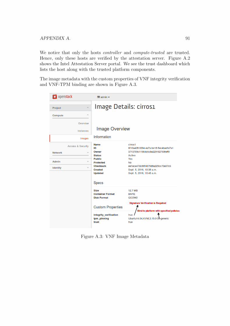
APPENDIX A. 91
We notice that only the hosts controller and compute-trusted are trusted.Hence, only these hosts are verified by the attestation server. Figure A.2shows the Intel Attestation Server portal. We see the trust dashboard whichlists the host along with the trusted platform components.
The image metadata with the custom properties of VNF integrity verificationand VNF-TPM binding are shown in Figure A.3.
Figure A.3: VNF Image Metadata
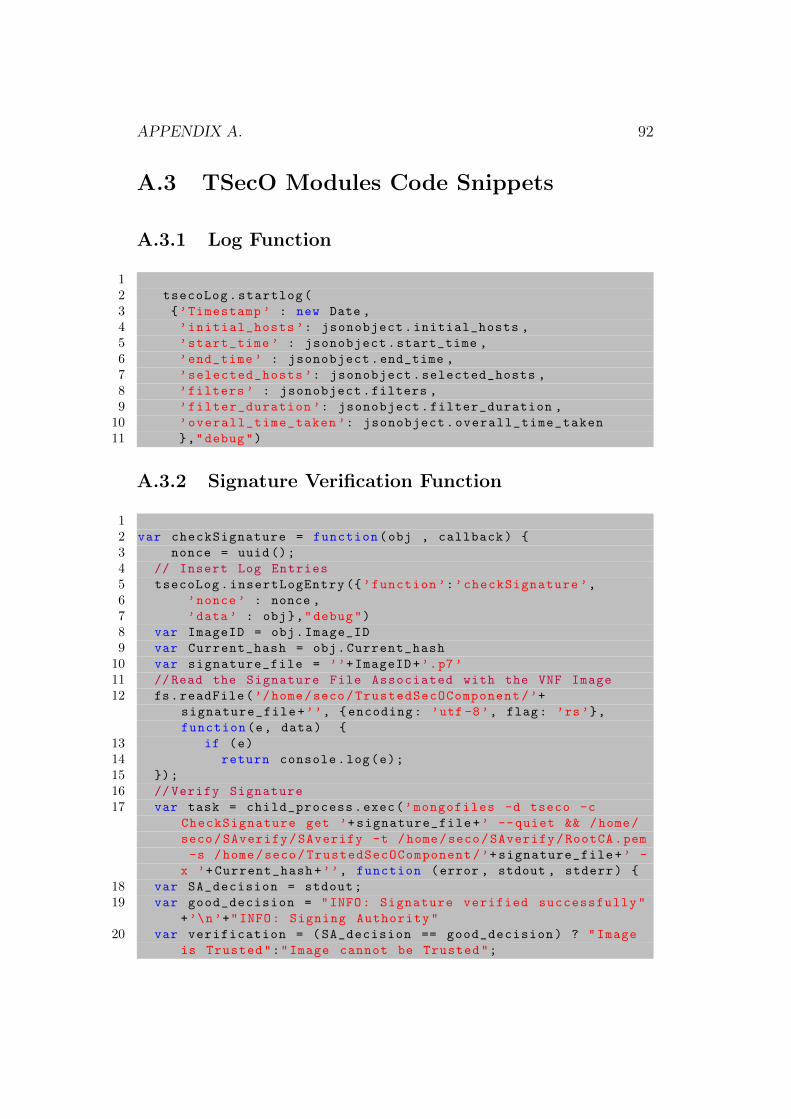
APPENDIX A. 92
A.3 TSecO Modules Code Snippets
A.3.1 Log Function
12 tsecoLog.startlog(
3 {’Timestamp ’ : new Date ,
4 ’initial_hosts ’: jsonobject.initial_hosts ,
5 ’start_time ’ : jsonobject.start_time ,
6 ’end_time ’ : jsonobject.end_time ,
7 ’selected_hosts ’: jsonobject.selected_hosts ,
8 ’filters ’ : jsonobject.filters ,
9 ’filter_duration ’: jsonobject.filter_duration ,
10 ’overall_time_taken ’: jsonobject.overall_time_taken
11 },"debug")
A.3.2 Signature Verification Function
12 var checkSignature = function(obj , callback) {
3 nonce = uuid();
4 // Insert Log Entries
5 tsecoLog.insertLogEntry ({’function ’:’checkSignature ’,
6 ’nonce’ : nonce ,
7 ’data’ : obj},"debug")
8 var ImageID = obj.Image_ID
9 var Current_hash = obj.Current_hash
10 var signature_file = ’’+ImageID+’.p7’
11 //Read the Signature File Associated with the VNF Image
12 fs.readFile(’/home/seco/TrustedSecOComponent/’+
signature_file+’’, {encoding: ’utf -8’, flag: ’rs’},
function(e, data) {
13 if (e)
14 return console.log(e);
15 });
16 // Verify Signature
17 var task = child_process.exec(’mongofiles -d tseco -c
CheckSignature get ’+signature_file+’ --quiet && /home/
seco/SAverify/SAverify -t /home/seco/SAverify/RootCA.pem
-s /home/seco/TrustedSecOComponent/’+signature_file+’ -
x ’+Current_hash+’’, function (error , stdout , stderr) {
18 var SA_decision = stdout;
19 var good_decision = "INFO: Signature verified successfully"
+’\n’+"INFO: Signing Authority"
20 var verification = (SA_decision == good_decision) ? "Image
is Trusted":"Image cannot be Trusted";
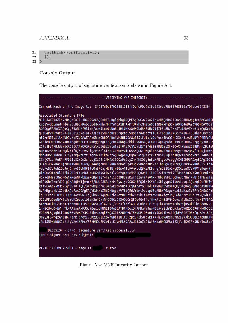
APPENDIX A. 93
21 callback(verification);
22 });
23 }
Console Output
The console output of signature verification is shown in Figure A.4.
Figure A.4: VNF Integrity Output
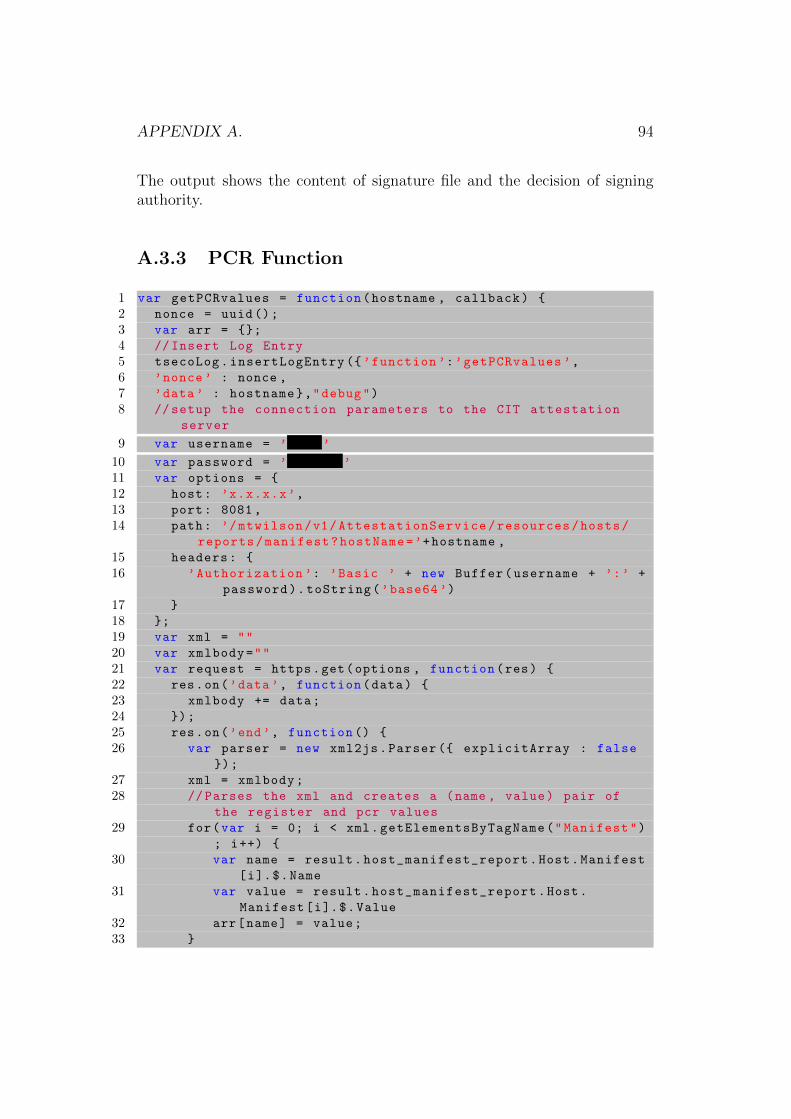
APPENDIX A. 94
The output shows the content of signature file and the decision of signingauthority.
A.3.3 PCR Function
1 var getPCRvalues = function(hostname , callback) {
2 nonce = uuid();
3 var arr = {};
4 // Insert Log Entry
5 tsecoLog.insertLogEntry ({’function ’:’getPCRvalues ’,
6 ’nonce’ : nonce ,
7 ’data’ : hostname},"debug")
8 // setup the connection parameters to the CIT attestation
server
9 var username = ’ ’
10 var password = ’ ’
11 var options = {
12 host: ’x.x.x.x’,
13 port: 8081,
14 path: ’/mtwilson/v1/AttestationService/resources/hosts/
reports/manifest?hostName=’+hostname ,
15 headers: {
16 ’Authorization ’: ’Basic ’ + new Buffer(username + ’:’ +
password).toString(’base64 ’)
17 }
18 };
19 var xml = ""
20 var xmlbody=""
21 var request = https.get(options , function(res) {
22 res.on(’data’, function(data) {
23 xmlbody += data;
24 });
25 res.on(’end’, function () {
26 var parser = new xml2js.Parser ({ explicitArray : false
});
27 xml = xmlbody;
28 // Parses the xml and creates a (name , value) pair of
the register and pcr values
29 for(var i = 0; i < xml.getElementsByTagName("Manifest")
; i++) {
30 var name = result.host_manifest_report.Host.Manifest
[i].$.Name
31 var value = result.host_manifest_report.Host.
Manifest[i].$.Value
32 arr[name] = value;
33 }
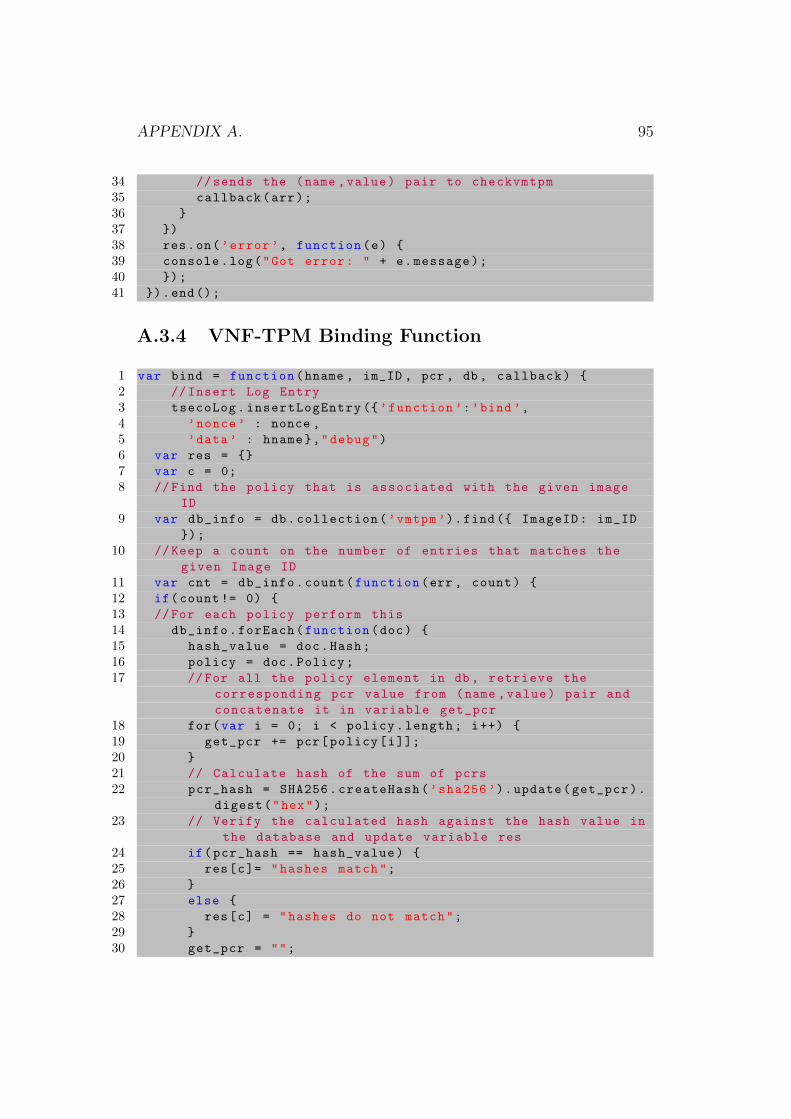
APPENDIX A. 95
34 //sends the (name ,value) pair to checkvmtpm
35 callback(arr);
36 }
37 })
38 res.on(’error’, function(e) {
39 console.log("Got error: " + e.message);
40 });
41 }).end();
A.3.4 VNF-TPM Binding Function
1 var bind = function(hname , im_ID , pcr , db , callback) {
2 // Insert Log Entry
3 tsecoLog.insertLogEntry ({’function ’:’bind’,
4 ’nonce’ : nonce ,
5 ’data’ : hname},"debug")
6 var res = {}
7 var c = 0;
8 //Find the policy that is associated with the given image
ID
9 var db_info = db.collection(’vmtpm’).find({ ImageID: im_ID
});
10 //Keep a count on the number of entries that matches the
given Image ID
11 var cnt = db_info.count(function(err , count) {
12 if(count!= 0) {
13 //For each policy perform this
14 db_info.forEach(function(doc) {
15 hash_value = doc.Hash;
16 policy = doc.Policy;
17 //For all the policy element in db , retrieve the
corresponding pcr value from (name ,value) pair and
concatenate it in variable get_pcr
18 for(var i = 0; i < policy.length; i++) {
19 get_pcr += pcr[policy[i]];
20 }
21 // Calculate hash of the sum of pcrs
22 pcr_hash = SHA256.createHash(’sha256 ’).update(get_pcr).
digest("hex");
23 // Verify the calculated hash against the hash value in
the database and update variable res
24 if(pcr_hash == hash_value) {
25 res[c]= "hashes match";
26 }
27 else {
28 res[c] = "hashes do not match";
29 }
30 get_pcr = "";
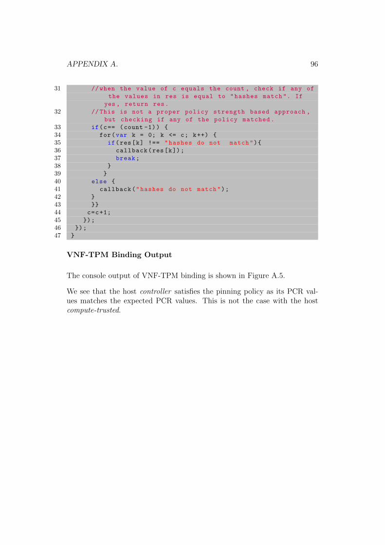
APPENDIX A. 96
31 //when the value of c equals the count , check if any of
the values in res is equal to "hashes match". If
yes , return res.
32 //This is not a proper policy strength based approach ,
but checking if any of the policy matched.
33 if(c== (count -1)) {
34 for(var k = 0; k <= c; k++) {
35 if(res[k] !== "hashes do not match"){
36 callback(res[k]);
37 break;
38 }
39 }
40 else {
41 callback("hashes do not match");
42 }
43 }}
44 c=c+1;
45 });
46 });
47 }
VNF-TPM Binding Output
The console output of VNF-TPM binding is shown in Figure A.5.
We see that the host controller satisfies the pinning policy as its PCR val-ues matches the expected PCR values. This is not the case with the hostcompute-trusted.
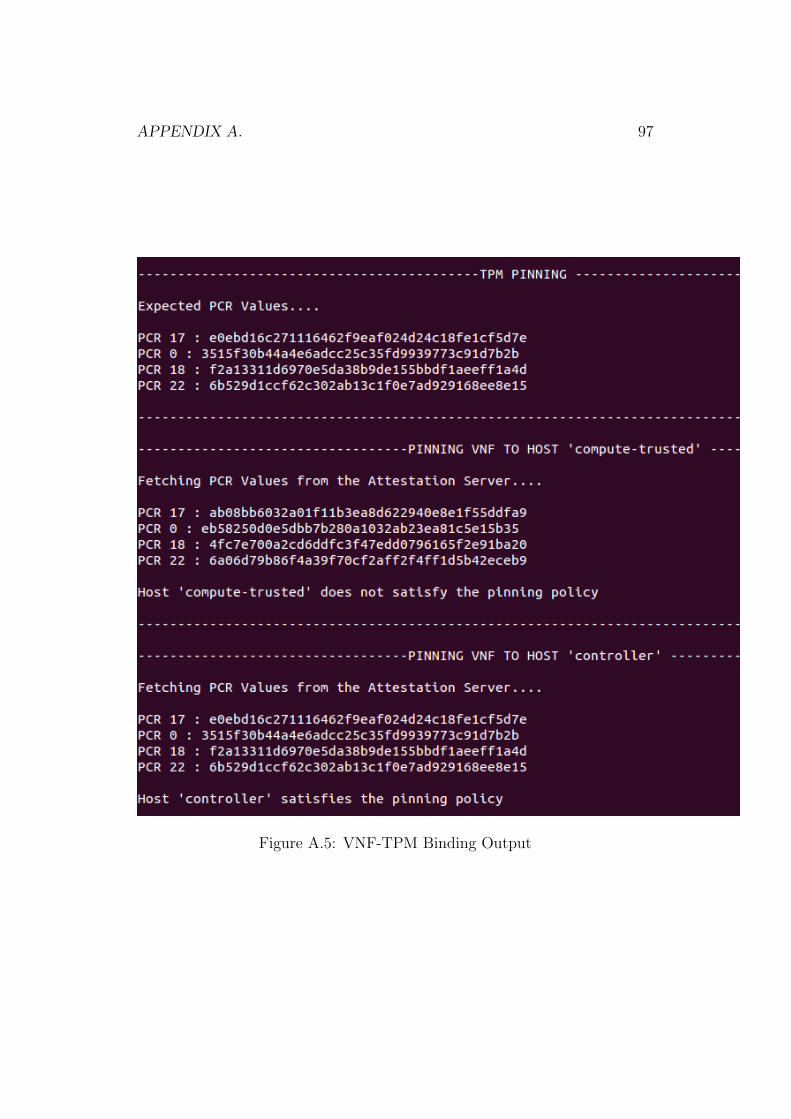
APPENDIX A. 97
Figure A.5: VNF-TPM Binding Output
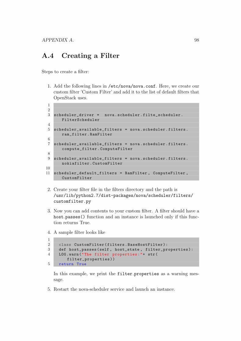
APPENDIX A. 98
A.4 Creating a Filter
Steps to create a filter:
1. Add the following lines in /etc/nova/nova.conf. Here, we create ourcustom filter ’Custom Filter’ and add it to the list of default filters thatOpenStack uses.
123 scheduler_driver = nova.scheduler.filte_scheduler.
FilterScheduler
45 scheduler_available_filters = nova.scheduler.filters.
ram_filter.RamFilter
67 scheduler_available_filters = nova.scheduler.filters.
compute_filter.ComputeFilter
89 scheduler_available_filters = nova.scheduler.filters.
nokiafilter.CustomFilter
1011 scheduler_default_filters = RamFilter , ComputeFilter ,
CustomFilter
2. Create your filter file in the filters directory and the path is/usr/lib/python2.7/dist-packages/nova/scheduler/filters/
customfilter.py
3. Now you can add contents to your custom filter. A filter should have ahost passes() function and an instance is launched only if this func-tion returns True.
4. A sample filter looks like
12 class CustomFilter(filters.BaseHostFilter):
3 def host_passes(self , host_state , filter_properties):
4 LOG.warn("The filter properties:"+ str(
filter_properties))
5 return True
In this example, we print the filter properties as a warning mes-sage.
5. Restart the nova-scheduler service and launch an instance.
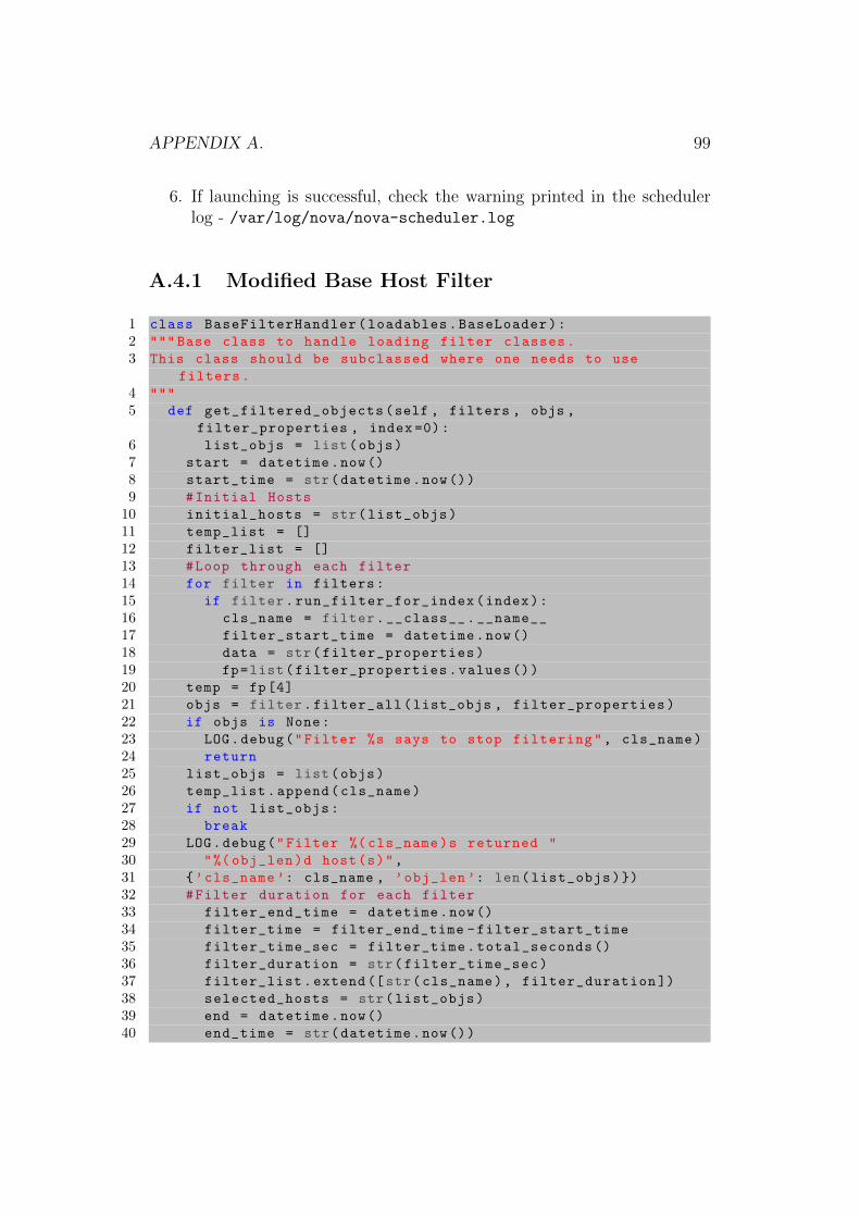
APPENDIX A. 99
6. If launching is successful, check the warning printed in the schedulerlog - /var/log/nova/nova-scheduler.log
A.4.1 Modified Base Host Filter
1 class BaseFilterHandler(loadables.BaseLoader):
2 """ Base class to handle loading filter classes.
3 This class should be subclassed where one needs to use
filters.
4 """
5 def get_filtered_objects(self , filters , objs ,
filter_properties , index =0):
6 list_objs = list(objs)
7 start = datetime.now()
8 start_time = str(datetime.now())
9 #Initial Hosts
10 initial_hosts = str(list_objs)
11 temp_list = []
12 filter_list = []
13 #Loop through each filter
14 for filter in filters:
15 if filter.run_filter_for_index(index):
16 cls_name = filter.__class__.__name__
17 filter_start_time = datetime.now()
18 data = str(filter_properties)
19 fp=list(filter_properties.values ())
20 temp = fp[4]
21 objs = filter.filter_all(list_objs , filter_properties)
22 if objs is None:
23 LOG.debug("Filter %s says to stop filtering", cls_name)
24 return
25 list_objs = list(objs)
26 temp_list.append(cls_name)
27 if not list_objs:
28 break
29 LOG.debug("Filter %( cls_name)s returned "
30 "%( obj_len)d host(s)",
31 {’cls_name ’: cls_name , ’obj_len ’: len(list_objs)})
32 #Filter duration for each filter
33 filter_end_time = datetime.now()
34 filter_time = filter_end_time -filter_start_time
35 filter_time_sec = filter_time.total_seconds ()
36 filter_duration = str(filter_time_sec)
37 filter_list.extend ([str(cls_name), filter_duration ])
38 selected_hosts = str(list_objs)
39 end = datetime.now()
40 end_time = str(datetime.now())
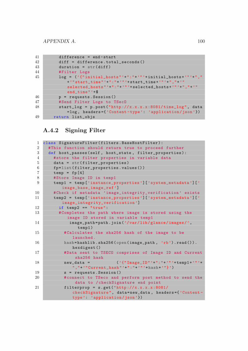
APPENDIX A. 100
41 difference = end -start
42 diff = difference.total_seconds ()
43 duration = str(diff)
44 #Filter Logs
45 log = (’{" initial_hosts"’+":"+’"’+initial_hosts+’"’+","
+’"start_time"’+":"+’"’+start_time+’"’+","+’"
selected_hosts"’+":"+’"’+selected_hosts+’"’+","+’"
end_time"’+$
46 p = requests.Session ()
47 #Send Filter Logs to TSecO
48 start_log = p.post("http ://x.x.x.x:8081/ time_log", data
=log , headers ={’Content -type’: ’application/json’})
49 return list_objs
A.4.2 Signing Filter
1 class SignatureFilter(filters.BaseHostFilter):
2 #This function should return true to proceed further
3 def host_passes(self , host_state , filter_properties):
4 #store the filter properties in variable data
5 data = str(filter_properties)
6 fp=list(filter_properties.values ())
7 temp = fp[4]
8 #Store Image ID in temp1
9 temp1 = temp[’instance_properties ’][’system_metadata ’][’
image_base_image_ref ’]
10 #Check if metadata ’image_integrity_verification ’ exists
11 temp2 = temp[’instance_properties ’][’system_metadata ’][’
image_integrity_verification ’]
12 if temp2 == "true":
13 #Completes the path where image is stored using the
image ID stored in variable temp1
14 image_path=path.join(’/var/lib/glance/images/’,
temp1)
15 #Calculates the sha256 hash of the image to be
launched.
16 hash=hashlib.sha256(open(image_path , ’rb’).read()).
hexdigest ()
17 #Data sent to TSECO comprises of Image ID and Current
sha256 hash
18 new_data = (’{" Image_ID"’+":"+’"’+temp1+’"’+
","+’"Current_hash"’+":"+’"’+hash+’"}’)
19 s = requests.Session ()
20 #connect to TSeco and perform post method to send the
data to /checkSignature end point
21 filterprop = s.get("http ://x.x.x.x:8081/
checkSignature", data=new_data , headers ={’Content -
type’: ’application/json’})
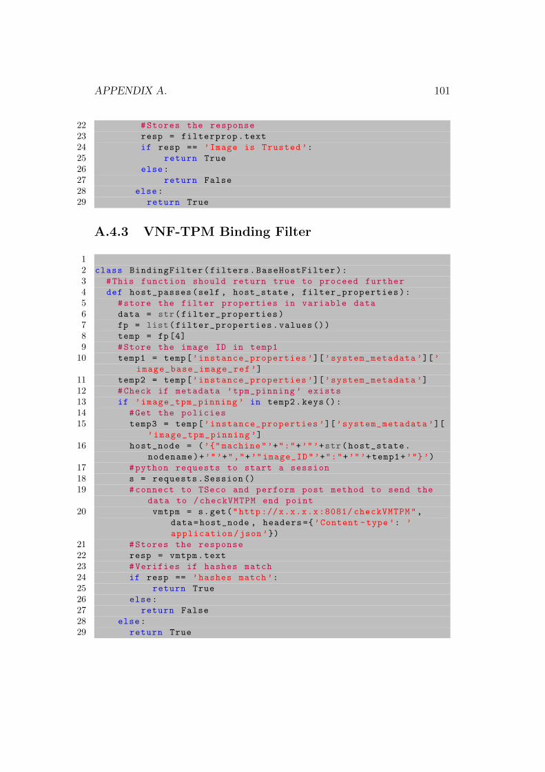
APPENDIX A. 101
22 #Stores the response
23 resp = filterprop.text
24 if resp == ’Image is Trusted ’:
25 return True
26 else:
27 return False
28 else:
29 return True
A.4.3 VNF-TPM Binding Filter
12 class BindingFilter(filters.BaseHostFilter):
3 #This function should return true to proceed further
4 def host_passes(self , host_state , filter_properties):
5 #store the filter properties in variable data
6 data = str(filter_properties)
7 fp = list(filter_properties.values ())
8 temp = fp[4]
9 #Store the image ID in temp1
10 temp1 = temp[’instance_properties ’][’system_metadata ’][’
image_base_image_ref ’]
11 temp2 = temp[’instance_properties ’][’system_metadata ’]
12 #Check if metadata ’tpm_pinning ’ exists
13 if ’image_tpm_pinning ’ in temp2.keys():
14 #Get the policies
15 temp3 = temp[’instance_properties ’][’system_metadata ’][
’image_tpm_pinning ’]
16 host_node = (’{" machine"’+":"+’"’+str(host_state.
nodename)+’"’+","+’"image_ID"’+":"+’"’+temp1+’"}’)
17 #python requests to start a session
18 s = requests.Session ()
19 #connect to TSeco and perform post method to send the
data to /checkVMTPM end point
20 vmtpm = s.get("http ://x.x.x.x:8081/ checkVMTPM",
data=host_node , headers ={’Content -type’: ’
application/json’})
21 #Stores the response
22 resp = vmtpm.text
23 #Verifies if hashes match
24 if resp == ’hashes match’:
25 return True
26 else:
27 return False
28 else:
29 return True
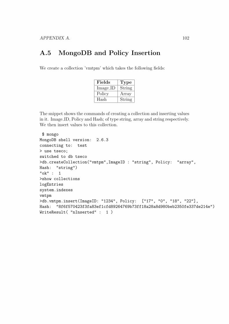
APPENDIX A. 102
A.5 MongoDB and Policy Insertion
We create a collection ’vmtpm’ which takes the following fields:
Fields TypeImage ID StringPolicy ArrayHash String
The snippet shows the commands of creating a collection and inserting valuesin it. Image ID, Policy and Hash; of type string, array and string respectively.We then insert values to this collection.
$ mongo
MongoDB shell version: 2.6.3
connecting to: test
> use tseco;
switched to db tseco
>db.createCollection("vmtpm",ImageID : "string", Policy: "array",
Hash: "string")
"ok" : 1
>show collections
logEntries
system.indexes
vmtpm
>db.vmtpm.insert(ImageID: "1234", Policy: ["17", "0", "18", "22"],
Hash: "8f6f570423f3fa83ef1cfd89264769b73ff18a28a8d980beb2350fe337de214e")
WriteResult( "nInserted" : 1 )