
Incorporating target mensuration system for target motion ... · INCORPORATING TARGET MENSURATION...
60
Calhoun: The NPS Institutional Archive Theses and Dissertations Thesis Collection 2006-12 Incorporating target mensuration system for target motion estimation along a road using asynchronous filter Yap, Kwee Chye. Monterey California. Naval Postgraduate School http://hdl.handle.net/10945/2427
Transcript of Incorporating target mensuration system for target motion ... · INCORPORATING TARGET MENSURATION...
Calhoun: The NPS Institutional Archive
Theses and Dissertations Thesis Collection
2006-12
Incorporating target mensuration system for target
motion estimation along a road using asynchronous filter
Yap, Kwee Chye.
Monterey California. Naval Postgraduate School
http://hdl.handle.net/10945/2427
NAVAL
POSTGRADUATE SCHOOL
MONTEREY, CALIFORNIA
THESIS
Approved for public release; distribution is unlimited
INCORPORATING TARGET MENSURATION SYSTEM FOR TARGET MOTION ESTIMATION ALONG A ROAD USING
ASYNCHRONOUS FILTER
by
Kwee Chye Yap
December 2006
Thesis Advisor: Isaac I. Kaminer Second Reader: Vladimir N. Dobrokhodov

THIS PAGE INTENTIONALLY LEFT BLANK

i
REPORT DOCUMENTATION PAGE Form Approved OMB No. 0704-0188 Public reporting burden for this collection of information is estimated to average 1 hour per response, including the time for reviewing instruction, searching existing data sources, gathering and maintaining the data needed, and completing and reviewing the collection of information. Send comments regarding this burden estimate or any other aspect of this collection of information, including suggestions for reducing this burden, to Washington headquarters Services, Directorate for Information Operations and Reports, 1215 Jefferson Davis Highway, Suite 1204, Arlington, VA 22202-4302, and to the Office of Management and Budget, Paperwork Reduction Project (0704-0188) Washington DC 20503. 1. AGENCY USE ONLY (Leave blank)
2. REPORT DATE December 2006
3. REPORT TYPE AND DATES COVERED Master’s Thesis
4. TITLE AND SUBTITLE: Incorporating Target Mensuration System for Target Motion Estimation Along a Road Using Asynchronous Filter 6. AUTHOR(S) Kwee Chye Yap
5. FUNDING NUMBERS
7. PERFORMING ORGANIZATION NAME(S) AND ADDRESS(ES) Naval Postgraduate School Monterey, CA 93943-5000
8. PERFORMING ORGANIZATION REPORT NUMBER
9. SPONSORING /MONITORING AGENCY NAME(S) AND ADDRESS(ES) SOCOM
10. SPONSORING/MONITORING AGENCY REPORT NUMBER
11. SUPPLEMENTARY NOTES The views expressed in this thesis are those of the author and do not reflect the official policy or position of the Department of Defense or the U.S. Government. 12a. DISTRIBUTION / AVAILABILITY STATEMENT Approved for public release; distribution is unlimited
12b. DISTRIBUTION CODE
13. ABSTRACT (maximum 200 words) In support of TNT experiments, the NPS UAV laboratory has developed a Vision-Based Target Tracking (VBTT) system for a Small Unmanned Aerial Vehicle (SUAV). This system provides an autonomous target tracking capability, while simultaneously estimating the target’s velocity and position. The accuracy of the existing system can be improved by providing external corrections to the target position estimation from the geo-rectification system (GIS). This thesis addresses the implementation of an asynchronous correction scheme into the target position estimation filter. The current autonomous position estimation algorithm provides 20-30 meters accuracy. The external correction system (Perspective View Nascent Technologies (PVNT)) is expected to provide target position accuracy of 1-2 m. However, a delay of up to 10 seconds is expected. Therefore, in order to improve the accuracy of current estimation of target motion, a new asynchronous correction technique that incorporates the more accurate PVNT data is proposed. To further improve the target motion estimation, it was also proposed to incorporate a known road model into the filter and compare its performance with the original filter.
15. NUMBER OF PAGES
59
14. SUBJECT TERMS Small Unmanned Air Vehicle, Asynchronous filter, Perspective View Nascent Technologies, Target motion estimation
16. PRICE CODE
17. SECURITY CLASSIFICATION OF REPORT
Unclassified
18. SECURITY CLASSIFICATION OF THIS PAGE
Unclassified
19. SECURITY CLASSIFICATION OF ABSTRACT
Unclassified
20. LIMITATION OF ABSTRACT
UL NSN 7540-01-280-5500 Standard Form 298 (Rev. 2-89) Prescribed by ANSI Std. 239-18

ii
THIS PAGE INTENTIONALLY LEFT BLANK

iii
Approved for public release; distribution is unlimited
INCORPORATING TARGET MENSURATION SYSTEM FOR TARGET MOTION ESTIMATION ALONG A ROAD USING ASYNCHRONOUS FILTER
Kwee Chye Yap
Lieutenant Colonel, Republic of Singapore Air Force B.Eng., University of Manchester, Institute of Science and Technology, 1990
Submitted in partial fulfillment of the requirements for the degree of
MASTER OF SCIENCE IN ENGINEERING SCIENCE (MECHANICAL ENGINEERING)
from the
NAVAL POSTGRADUATE SCHOOL December 2006
Author: Kwee Chye Yap
Approved by: Isaac I. Kaminer Thesis Advisor
Vladimir N. Dobrokhodov Second Reader
Anthony J. Healey Chairman, Department of Mechanical and Astronautical Engineering

iv
THIS PAGE INTENTIONALLY LEFT BLANK

v
ABSTRACT
In support of TNT experiments, the NPS UAV laboratory has developed a Vision-
Based Target Tracking (VBTT) system for a Small Unmanned Aerial Vehicle (SUAV).
This system provides an autonomous target tracking capability, while simultaneously
estimating the target’s velocity and position. The accuracy of the existing system can be
improved by providing external corrections to the target position estimation from the geo-
rectification system (GIS). This thesis addresses the implementation of an asynchronous
correction scheme into the target position estimation filter. The current autonomous
position estimation algorithm provides 20-30 meters accuracy. The external correction
system (Perspective View Nascent Technologies (PVNT)) is expected to provide target
position accuracy of 1-2 m. However, a delay of up to 10 seconds is expected. Therefore,
in order to improve the accuracy of current estimation of target motion, a new
asynchronous correction technique that incorporates the more accurate PVNT data is
proposed. To further improve the target motion estimation, it was also proposed to
incorporate a known road model into the filter and compare its performance with the
original filter.

vi
THIS PAGE INTENTIONALLY LEFT BLANK

vii
TABLE OF CONTENTS
I. INTRODUCTION........................................................................................................1 A. OVERVIEW.....................................................................................................1 B. MOTIVATION ................................................................................................1
II. BACKGROUND ..........................................................................................................3 A. PERSPECTIVE VIEW NASCENT TECHNOLOGIES (PVNT) ...............3 B. GENERIC ASYCHRONOUS KALMAN FILTER......................................4
III. PROBLEM DEFINITION ..........................................................................................7 A. CURRENT ARCHITECTURE ......................................................................7 B. PROBLEM DEFINITION ..............................................................................8 C. OBJECTIVES ..................................................................................................8
IV. FILTER DEVELOPMENT ........................................................................................9 A. GENERAL ASYNCHRONOUS FILTER.....................................................9
1. True Target Vehicle Model .................................................................9 2. PVNT Model.......................................................................................10 3. Data Storage .......................................................................................10 4. Filter ....................................................................................................11
B. ROAD FOLLOWING ASYNCHRONOUS FILTER ................................11 1. True Target Vehicle Model with Road Following
Characteristics....................................................................................12 2. PVNT Model.......................................................................................13 3. Filter ....................................................................................................13 4. Optimization.......................................................................................13
V. SIMULATION ...........................................................................................................15 A. FRAME REFERENCE .................................................................................15 B. DURATION....................................................................................................15 C. SAMPLE TIME .............................................................................................15 D. ROAD MODEL..............................................................................................15 E. MEASURE OF PERFORMANCE (MOP) .................................................16 F. FILTER COMPARISON..............................................................................16
1. K1 and K2 Gains................................................................................16 2. PVNT Delay........................................................................................17 3. PVNT Noise ........................................................................................17
VI. RESULTS AND ANALYSIS ....................................................................................19 A. FILTER PERFORMANCE WITH K1 AND K2 VALUES.......................19
1. Results .................................................................................................19 2. Analysis ...............................................................................................21
B. FILTER PERFORMANCE WITH PVNT DELAY...................................21 1. Results .................................................................................................22 2. Analysis ...............................................................................................24
C. FILTER PERFORMANCE WITH PVNT NOISE ....................................25

viii
1. Results .................................................................................................25 2. Analysis ...............................................................................................27
D. GENERAL ASYNCHRONOUS FILTER PERFORMANCE ..................27 E. ROAD FOLLOWING ASYNCHRONOUS FILTER
PERFORMANCE..........................................................................................32
VII. CONCLUSION AND RECOMMENDATION .......................................................39 A. CONCLUSION ..............................................................................................39 B. RECOMMENDATION.................................................................................39
LIST OF REFERENCES......................................................................................................41
INITIAL DISTRIBUTION LIST .........................................................................................43

ix
LIST OF FIGURES
Figure 1. Flight set-up and PVNT workstation [After: Ref 1]. .........................................4 Figure 2. Current architecture ...........................................................................................7 Figure 3. Visual representation of PVNT updates arriving at time t for τ .......................8 Figure 4. General asynchronous filter ...............................................................................9 Figure 5. True target vehicle model ................................................................................10 Figure 6. PVNT model ....................................................................................................10 Figure 7. Simulink model of filter in general asynchronous filter ..................................11 Figure 8. Road following asynchronous filter.................................................................12 Figure 9. True vehicle model with road following characteristics..................................12 Figure 10. Simulink model of filter in road following asynchronous filter ......................13 Figure 11. Simulated road profile......................................................................................16 Figure 12. Target velocity rms errors vs K1/K2 values (general asynchronous filter) .....19 Figure 13. Target position rms errors vs K1/K2 values (general asynchronous filter) .....20 Figure 14. Target velocity rms errors vs K1/K2 values (road following asynchronous
filter) ................................................................................................................20 Figure 15. Target position rms errors vs K1/K2 values (road following asynchronous
filter) ................................................................................................................21 Figure 16. Target velocity rms errors vs PVNT delay (general asynchronous filter) .......22 Figure 17. Target position rms errors vs PVNT delay (general asynchronous filter) .......23 Figure 18. Target velocity rms errors vs PVNT delay (road following asynchronous
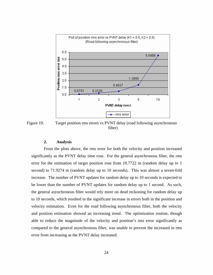
filter) ................................................................................................................23 Figure 19. Target position rms errors vs PVNT delay (road following asynchronous
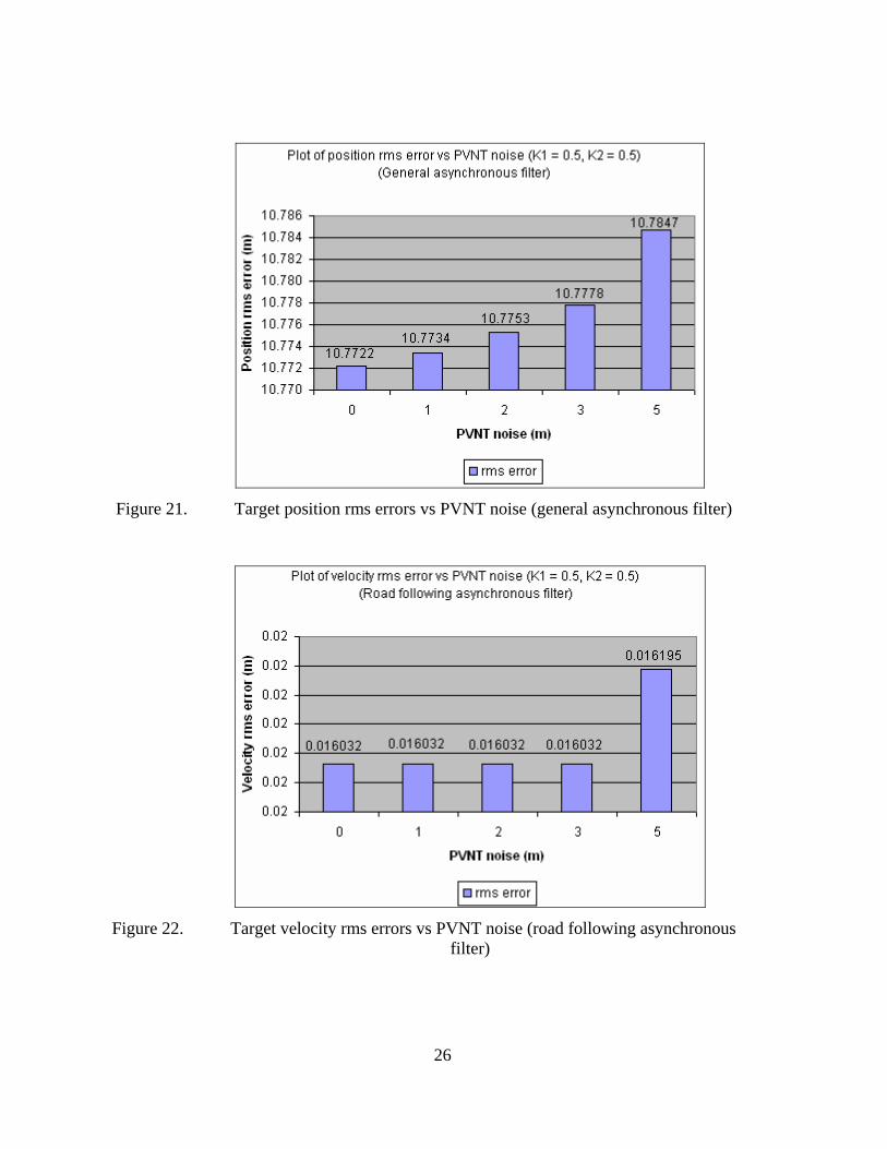
filter) ................................................................................................................24 Figure 20. Target velocity rms errors vs PVNT noise (general asynchronous filter) .......25 Figure 21. Target position rms errors vs PVNT noise (general asynchronous filter) .......26 Figure 22. Target velocity rms errors vs PVNT noise (road following asynchronous
filter) ................................................................................................................26 Figure 23. Target position rms errors vs PVNT noise (road following asynchronous
filter) ................................................................................................................27 Figure 24. Actual vs Estimated target position (general asynchronous filter) ..................28 Figure 25. Errors in x-direction position (general asynchronous filter)............................28 Figure 26. Errors in y-direction position (general asynchronous filter)............................29 Figure 27. Velocity profile in the x-direction (general asynchronous filter) ....................30 Figure 28. Error in the x-direction velocity (general asynchronous filter) .......................30 Figure 29. Velocity profile in the y-direction (general asynchronous filter) ....................31 Figure 30. Error in the y-direction velocity (general asynchronous filter) .......................31 Figure 31. Actual vs Estimated target position (road following asynchronous filter) ......32 Figure 32. Errors in x-direction position (road following asynchronous filter)................33 Figure 33. Expanded plot for errors in x-direction position (road following
asynchronous filter) .........................................................................................33 Figure 34. Errors in y-direction position (road following asynchronous filter)................34

x
Figure 35. Expended plot for errors in y-direction position (road following asynchronous filter) .........................................................................................34
Figure 36. Velocity profile in the x-direction (road following asynchronous filter) ........35 Figure 37. Error in the x-direction velocity (road following asynchronous filter)............36 Figure 38. Velocity profile in the y-direction (road following asynchronous filter) ........36 Figure 39. Error in the y-direction velocity (road following asynchronous filter)............37

xi
LIST OF TABLES
Table 1. Variation of K1 and K2....................................................................................19 Table 2. Variation of PVNT delays ...............................................................................22 Table 3. Variation of PVNT noise .................................................................................25

xii
THIS PAGE INTENTIONALLY LEFT BLANK
xiii
ACKNOWLEDGMENTS
The author would like to thank Professor Isaac I. Kaminer for his continuous
effort in explaining the concepts and requirements of designing the new filter for the
thesis. His dedicated effort made the learning process enjoyable. He would also like to
thank Dr. Vladimir N. Dobrokhodov for his invaluable advices and explanations
throughout the thesis process. This thesis has enriched the author’s understanding in both
the academic and technical areas of Unmanned Aerial Vehicle’s tracking of targets and
will provide the necessary expertise in his future endeavors.
The author would like to express his gratitude to his wife, Gelin, who has
supported him throughout the year when he was doing his course in NPS. Her
continuous support and encouragement have made the thesis process painless.

xiv
THIS PAGE INTENTIONALLY LEFT BLANK
1
I. INTRODUCTION
A. OVERVIEW The main goal of this thesis was to design a new filter that is able to provide a
better estimation of target motion. This new filter would complement the current non-
linear target motion estimation filter mounted on a Small Unmanned Aerial Vehicle
(SUAV). Naval Postgraduate School (NPS) is a participant in the Tactical Network
Topology (TNT) field experimentation program, which includes United States Special
Operations Command (USSOCOM), its component commands and several government
laboratories. The field experimentations are part of the Surveillance and Target
Acquisition (STAN) program. Quarterly field experiments are conducted at the Center for
Inter-disciplinary Remotely-Piloted Aircraft Studies (CIRPAS) facility located at
McMillan Field in Camp Roberts, California. These experiments aim to explore and
demonstrate new technologies that are applicable to the military, with special focus on
sensor and wireless network, autonomous vehicle and target tracking/identification.
B. MOTIVATION The NPS SUAV is designed with Commercial Off-the-Shelf sensors that reduced
the cost of operating the SUAV. The main role of the SUAV is in the surveillance and
reconnaissance arena.
The utilization of Vision-Based Target Tracking (VBTT) allows a passive mode
of target tracking and reduces the risk of exposure of the UAV when it conducts its
surveillance. This would enhance the security of the SUAV operation.
Currently, the VBTT system utilizes a filter to estimate the position of the target.
A coordinated control strategy is employed that estimates the position of the target using
the turn rate of the Line-of-Sight (LOS) between the UAV and the target.
The accuracy of the estimated target motion can be improved if an external
correction is made to the estimated target position obtained from the current filter. One
of the possible correction methods can be obtained from the Perspective View Nascent
Technologies (PVNT). This technology will be described in more details in Chapter 2.
The PVNT software is able to provide a correction to the estimated target position up to 1

2
meter accuracy. However, this updated target position would only be made available
about 1 to 10 seconds later. Thus, there is a need to develop an asynchronous filter to
incorporate this updated position.
To further improve the performance of the new asynchronous filter, it is also
proposed that a known road model be incorporated into the filter. The performance of
this road-following asynchronous filter will be compared to the original filter to
determine the anticipated improvement that may be achieved.
3
II. BACKGROUND
A. PERSPECTIVE VIEW NASCENT TECHNOLOGIES (PVNT) The PVNT system was developed by Dr. Wolfgang Baer, a professor at the Naval
Postgraduate School (NPS) in Monterey, California. The initial PVNT software was
designed for tactical weapon testing. The software provided a 3D battlefield simulation
and allowed the UAV to carry out target locating functions. The use of low-cost PC-
based software helped to reduce the overall cost of the system. Currently, the PVNT
software is capable of generating 1-meter-resolution terrain data for large area tactical
battlefield simulations and uses it to create perspective views. These perspective views
are employed to perform both line-of-sight (LOS) and weapon effectiveness analysis. At
present, PVNT databases cover locations such as Fort Hunter Liggett, California and
Camp Roberts, California.
One of the more unique features of the PVNT program is the use of raster formats
(pixel) as storage for terrain surface, as opposed to polygon database that is used by most
scene-visualization programs on the market. This makes PVNT more suitable for
handling data that is gathered by remote sensors, and ideal for integration with tactical
battlefield sensor systems.
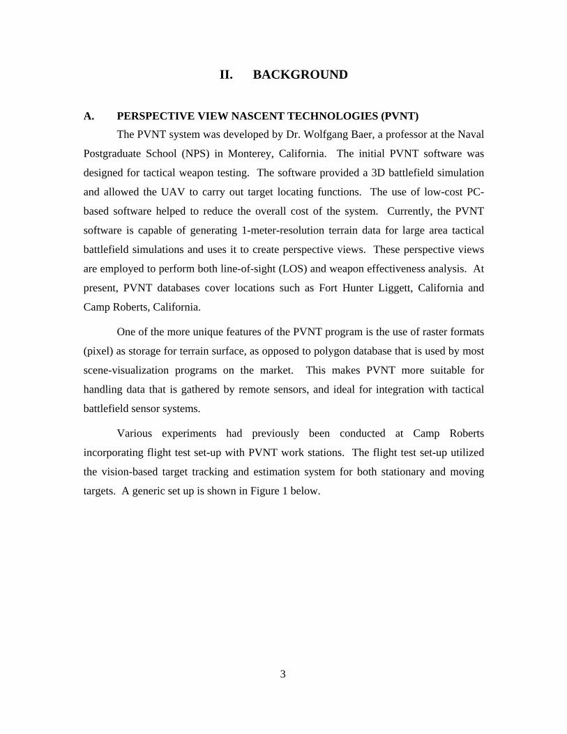
Various experiments had previously been conducted at Camp Roberts
incorporating flight test set-up with PVNT work stations. The flight test set-up utilized
the vision-based target tracking and estimation system for both stationary and moving
targets. A generic set up is shown in Figure 1 below.
4
Figure 1. Flight set-up and PVNT workstation [After: Ref 1].
During flight tests, images captured by the onboard camera mounted on the
SUAV were broadcast and processed by OTS PerceptiVU image processing software
[Ref 2]. Non-linear filtering algorithms (Figure 2) developed at NPS estimated the target
geo-location’s accuracy to about 10-20 m with 10-20 seconds of tracking. Working in
parallel, the images captured from the SUAV and the estimated position of the target
obtained from the filtering are shared over the network and fed to the PVNT vision-based
target tracking system.
The PVNT software compared the images received from the SUAV, together with
GPS and camera angle coordinates, with the database information. The accuracy of the
target position is determined almost solely by the accuracy of the database (currently at 1
m resolution). Thus, using the PVNT-image mensuration system would yield the target
position estimates to within 1-2 m. However, due to the processing time required in
comparing the target images with the PVNT database, there would be a time lapse
(currently about 1 to 10 seconds) between the time the image of the target is fed to the
PVNT system and the updated position of the target obtained from the PVNT system.
B. GENERIC ASYCHRONOUS KALMAN FILTER In motion tracking, the standard Kalman filter has been extensively employed.
However, such a filter requires synchronous and equi-distant measurement updates to
ensure robust and accurate prediction. In many applications, such updates may not be
5
practical or even possible. Many enhancements to the standard Kalman filters were made
[Ref 5, 6] to accept out-of-sequence, sporadic or infrequent updates to the filter. Such
filters are typically known as asynchronous filters.
Asynchronous Kalman filters have been used in various applications. One of the
more common applications is in sensor fusion. In sensor fusion applications, standard
and extended Kalman filters are popular due to the ease of blending the various sensors’
data to provide an optimal estimate. Sensors measuring target’s velocity and/or
accelerations can be blended with sensors measuring its direct position to give an optimal
estimate of the target. However, Kalman filters require specific and consistent
information for their current iteration in providing accurate prediction of the future states.
Any interruption in any sensors update rate would degrade the effectiveness of a simple
Kalman filter. Thus, asynchronous filters are designed to ensure that the effectiveness of
the Kalman filters is not degraded with asynchronous updates from the sensors.
The implementation of the asynchronous Kalman filter can also take various
forms. In the paper “Adaptable Sensor Fusion Using Multiple Kalman Filters” [Ref 7],
the authors proposed the use of multiple Kalman filters to allow asynchronous inputs
from sensors. The central idea of the paper is the use of a bank of Kalman filters to
represent the various combinations of sensors. As the data acquisition rate differs on the
various sensors, a sensor fusion algorithm allows the selection of the appropriate model
to account for the new data that is available at each iteration. Such switching alleviates
the need to receive information from all sensors at every iteration.
In this thesis, an asynchronous filter is developed to incorporate the delayed but
more accurate target position estimates from PVNT.

6
THIS PAGE INTENTIONALLY LEFT BLANK

7
III. PROBLEM DEFINITION
A. CURRENT ARCHITECTURE
Figure 2. Current architecture
Figure 2 depicts the current architecture for target tracking using SUAV in NPS.
A system to track a target and estimate both its velocity and position has been in
development over the years in NPS. Constant improvements have been made to the
initial concept of target tracking. The current control system uses a nonlinear filter for
target estimation [Ref 8]. This filter has shown stability in motion target estimation and
graceful degradation of performance during target loss events. The filter has been flight
tested using a moving target and is capable of estimating target position to an accuracy of
20 meters. Both the target’s velocity and position estimations are available in real time.
In parallel, the target image captured by the onboard camera of the small UAV is
sent to the PVNT system as described in Chapter II. From PVNT, the target position
estimation is expected to be 1-2 meters but with a delay of up to 10 seconds.

8
B. PROBLEM DEFINITION
Figure 3. Visual representation of PVNT updates arriving at time t for τ
In the diagram above, a target is traveling along a simulated road. At time τ , the
captured image of the target is sent to PVNT for processing. At the same time, the
nonlinear filter onboard the UAV is processing the target image and estimating the
position of the target. At time t (t > τ ), when the target has traveled a finite distance
along the road, an updated target position for time τ arrived from PVNT. The present
filter would not be able to use this information to provide a better estimation of the
target’s position and velocity.
C. OBJECTIVES To provide a better target motion estimation using the more accurate but delayed
PVNT position update, a new filter would be designed. This filter would be able to use
the PVNT position and provide a more accurate velocity and position update at time t.
To further enhance the filter, this thesis would also examine the performance of the filter
that incorporates the road profile that the target is traveling on.

9
IV. FILTER DEVELOPMENT
A. GENERAL ASYNCHRONOUS FILTER The following diagram shows the design of the new general asynchronous filter
that was developed to estimate target motion (both velocity and position) using delayed
PVNT target position estimation.
Figure 4. General asynchronous filter
1. True Target Vehicle Model A true target vehicle model was created in Simulink. It served two purposes. The
first purpose was to generate the target’s velocity and position vectors in Local Tangent
Plane. Generated positions of the target were fed to the PVNT model to provide delayed
position of the target. The second purpose was to compare the target’s actual velocity
and position with the filter’s estimates. The Simulink model of the true vehicle model is
shown below.

10
Figure 5. True target vehicle model
2. PVNT Model The purpose of the PVNT model was to simulate the delayed data received from
the PVNT software. In Simulink, the PVNT model received position data from the true
vehicle model, and using a Matlab script file generated delayed target position based on
the delay timing specified by the user. PVNT noise can also be added to the generated
target position. A Simulink diagram of the PVNT model is shown below.
Figure 6. PVNT model
3. Data Storage In the model, a data storage model is generated to store the target’s velocity and
position data. Both the true and estimated velocity and position are stored. This data is
marked with a time stamp that allows it to be retrieved based on the time lapse between

11
the current time and the delayed time of the PVNT update. The filter has been designed
to cater for varying delay times.
4. Filter The Simulink model of the filter that was designed is shown below.
Figure 7. Simulink model of filter in general asynchronous filter
This filter uses dead-reckoning when there is no PVNT update. It is initiated
based on the initial estimate of the target’s velocity and position. The gains (K1 and K2)
are fixed. When the delayed PVNT update arrives (at time t for data at time τ ), the filter
integrates backward and forward in time (from time τ to t) using PVNT delayed data.
The output from the filter is an updated target velocity and position at time t. Both the
velocity and position data at time t are used to re-initialize the open-looped filter to
provide the target’s velocity and position from time t.
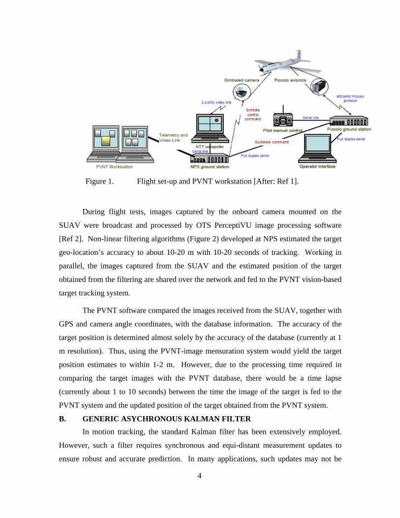
B. ROAD FOLLOWING ASYNCHRONOUS FILTER The road following asynchronous filter was developed from the general
asynchronous filter with some modifications. The diagram shows the Simulink
representation of the road following asynchronous filter. The main difference for the
road following asynchronous filter is the use of a parameter, ρ (path length of the road),
to characterize the road that the target vehicle is moving on. This parameter is chosen
because its derivative, ρ , is the speed of the vehicle at any point on the road. The
12
differences in the various models within the general asynchronous filter and the road
following asynchronous filter are highlighted in the next few paragraphs.
Figure 8. Road following asynchronous filter
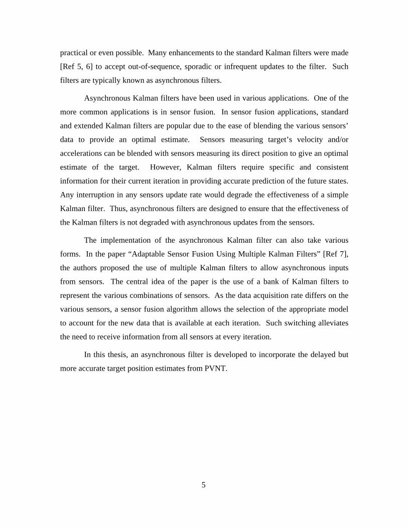
1. True Target Vehicle Model with Road Following Characteristics The following diagram is the modified true target vehicle model.
Figure 9. True vehicle model with road following characteristics
The main difference with the true vehicle model in the road following
asynchronous filter is the use of the path length parameter to characterize the road. The
values of the generated true path length as well as the speed of the vehicle are stored to be
used when the PVNT position update arrives.

13
2. PVNT Model The PVNT model for the road following asynchronous filter is the same as the
one used for general asynchronous filter.
3. Filter The asynchronous filter used in this section is shown in Figure 10. Both the
inputs and outputs of this filter (shown below) are scalar (path length and speed).
Figure 10. Simulink model of filter in road following asynchronous filter
4. Optimization An optimization routine is implemented with the road following asynchronous
filter to determine the path length parameter, ρ . The minimization equation is as shown.
( ) ( ) ( )2 2 2min ( ) ( ) ( )x xPVNT y yPVNT z zPVNTρ
ρ ρ ρ⎡ ⎤− + − + −⎣ ⎦ (1)

14
THIS PAGE INTENTIONALLY LEFT BLANK

15
V. SIMULATION
A. FRAME REFERENCE The frame reference used during the simulation is the Local Tangent Plane (LTP).
B. DURATION The simulation duration is set at 180 seconds.
C. SAMPLE TIME The sample timing used during the simulation is fixed at 0.1 second rate. For a
simulation of 180 seconds, this equates to 1800 data points.
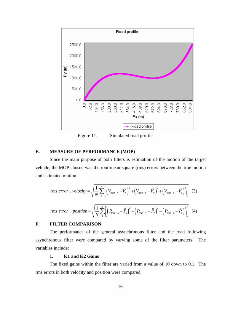
D. ROAD MODEL In the simulation, the following equations are used to model the road.
3 2
( )( ) 0.0000192 0.025 9.74( ) 0
road
xP y
z
ρ ρρ ρ ρ ρρ
⎡ ⎤ ⎡ ⎤⎢ ⎥ ⎢ ⎥= = − +⎢ ⎥ ⎢ ⎥⎢ ⎥ ⎢ ⎥⎣ ⎦ ⎣ ⎦
(2)
A cubic representation of the road was chosen for the simulation to ensure that the
profile chosen would not be a monotonically increasing function of the path length. The
road profile in x-y representation is 3 20.0000192 0.025 9.74y x x x= − + and a visual
representation of this road profile is shown in Figure 11.
16
Figure 11. Simulated road profile
E. MEASURE OF PERFORMANCE (MOP) Since the main purpose of both filters is estimation of the motion of the target
vehicle, the MOP chosen was the root-mean-square (rms) errors between the true motion
and estimated motion.
( ) ( ) ( )2 2 2
_ _ _1
1 ˆ ˆ ˆ_N
true x x true y y true z zrms error velocity V V V V V VN
⎡ ⎤= − + − + −⎢ ⎥⎣ ⎦∑ (3)
( ) ( ) ( )2 2 2
_ _ _1
1 ˆ ˆ ˆ_N
true x x true y y true z zrms error position P P P P P PN
⎡ ⎤= − + − + −⎢ ⎥⎣ ⎦∑ (4)
F. FILTER COMPARISON The performance of the general asynchronous filter and the road following
asynchronous filter were compared by varying some of the filter parameters. The
variables include:
1. K1 and K2 Gains The fixed gains within the filter are varied from a value of 10 down to 0.1. The
rms errors in both velocity and position were compared.

17
2. PVNT Delay The expected delay from PVNT was randomized with increasing magnitude (from
1 to 10 seconds). The rms errors in both velocity and position were again compared.
3. PVNT Noise Lastly, the PVNT noise (errors that can be expected from the PVNT software) is
also varied within each filter. The noise added to the PVNT position ranged from +/- 1
meter to 5 meters. Similarly, the rms errors in both velocity and position were compared.

18
THIS PAGE INTENTIONALLY LEFT BLANK

19
VI. RESULTS AND ANALYSIS
A. FILTER PERFORMANCE WITH K1 AND K2 VALUES To examine the filter performance based on variation of K1 and K2 values, the
other two parameters were fixed. The PVNT delay is random but does not exceed 1
second while the PVNT noise is set at +/- 0 meter (i.e. no noise). The K1 and K2 gains
are fixed at the following values shown in the table below.
Table 1. Variation of K1 and K2
Runs conducted K1 K2
Run 1 10 10
Run 2 5 5
Run 3 1 1
Run 4 0.5 0.5
Run 5 0.1 0.1
1. Results The following four plots show the results obtained for both the general and road
following asynchronous filters for the rms errors obtained for the target’s velocity and
position.
Figure 12. Target velocity rms errors vs K1/K2 values (general asynchronous filter)
20
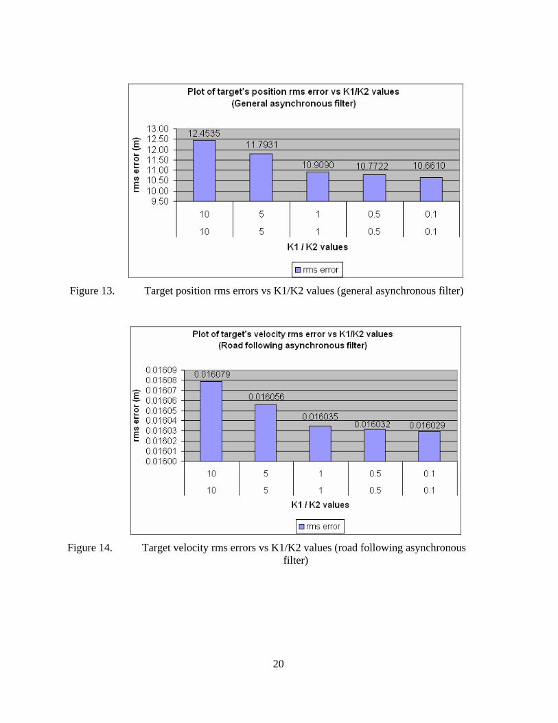
Figure 13. Target position rms errors vs K1/K2 values (general asynchronous filter)
Figure 14. Target velocity rms errors vs K1/K2 values (road following asynchronous
filter)

21
Figure 15. Target position rms errors vs K1/K2 values (road following asynchronous
filter)
2. Analysis For both filters, decreasing the gains from 10 to 0.1 resulted in a decrease in the
rms errors for both velocity and position estimations. In both filters, the gains K1 and K2
were activated only when there was a PVNT update. For the simulation, this equates to
about 10% (180 PVNT updates over 1800 data points) of the simulation time. As such,
although a smaller gain is desired, the rms errors resultig from the different gains did not
differ significantly.
B. FILTER PERFORMANCE WITH PVNT DELAY To examine the filter performance based on PVNT delays, the other two
parameters were fixed. The K1 and K2 values are fixed at 0.5 while the PVNT noise was
set at +/- 0 meter (i.e. no noise). The PVNT delays are random, but cannot exceed the
values shown in Table 2.
22
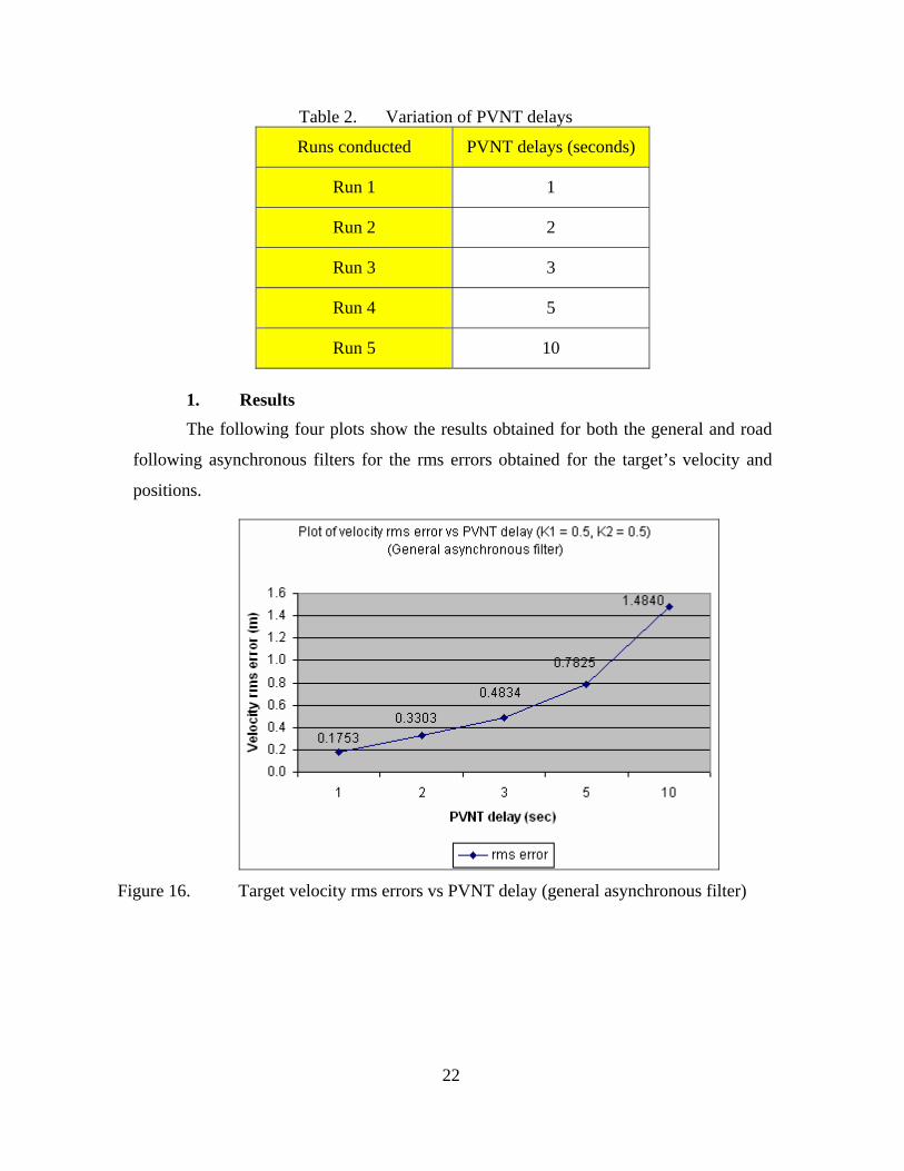
Table 2. Variation of PVNT delays
Runs conducted PVNT delays (seconds)
Run 1 1
Run 2 2
Run 3 3
Run 4 5
Run 5 10
1. Results The following four plots show the results obtained for both the general and road
following asynchronous filters for the rms errors obtained for the target’s velocity and
positions.
Figure 16. Target velocity rms errors vs PVNT delay (general asynchronous filter)
23
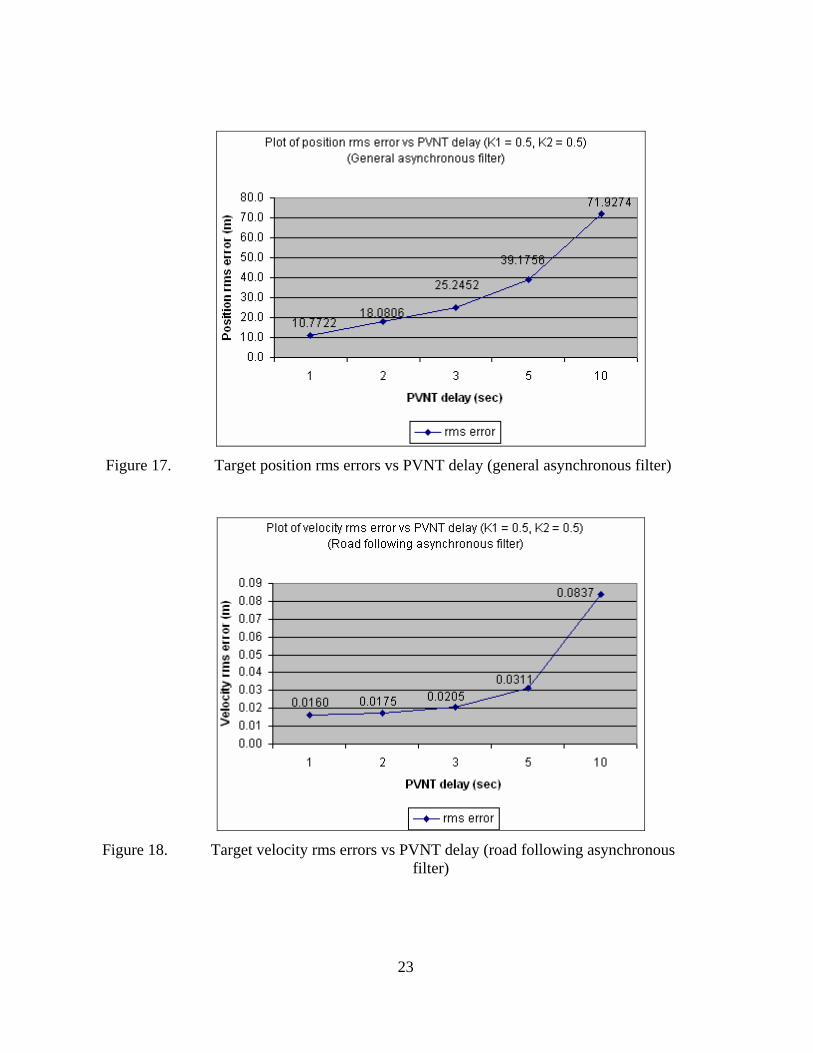
Figure 17. Target position rms errors vs PVNT delay (general asynchronous filter)
Figure 18. Target velocity rms errors vs PVNT delay (road following asynchronous
filter)
24
Figure 19. Target position rms errors vs PVNT delay (road following asynchronous
filter)
2. Analysis From the plots above, the rms error for both the velocity and position increased
significantly as the PVNT delay time rose. For the general asynchronous filter, the rms
error for the estimation of target position rose from 10.7722 m (random delay up to 1
second) to 71.9274 m (random delay up to 10 seconds). This was almost a seven-fold
increase. The number of PVNT updates for random delay up to 10 seconds is expected to
be lower than the number of PVNT updates for random delay up to 1 second. As such,
the general asynchronous filter would rely more on dead reckoning for random delay up
to 10 seconds, which resulted in the significant increase in errors both in the position and
velocity estimation. Even for the road following asynchronous filter, both the velocity
and position estimation showed an increasing trend. The optimization routine, though
able to reduce the magnitude of the velocity and position’s rms error significantly as
compared to the general asynchronous filter, was unable to prevent the increased in rms
error from increasing as the PVNT delay increased.

25
C. FILTER PERFORMANCE WITH PVNT NOISE To examine the filter performance based on PVNT noise, the other two
parameters were fixed. The K1 and K2 values were fixed at 0.5 while the PVNT delay
was random but did not exceed 1 meter. The PVNT noise was fixed at the following
values shown in the table below.
Table 3. Variation of PVNT noise
Runs conducted PVNT noise (meter)
Run 1 0±
Run 2 1±
Run 3 2±
Run 4 3±
Run 5 5±
1. Results The following four plots show results obtained for both the general and road
following asynchronous filters for the rms errors obtained for the target’s velocity and
positions.
Figure 20. Target velocity rms errors vs PVNT noise (general asynchronous filter)
26
Figure 21. Target position rms errors vs PVNT noise (general asynchronous filter)
Figure 22. Target velocity rms errors vs PVNT noise (road following asynchronous
filter)

27
Figure 23. Target position rms errors vs PVNT noise (road following asynchronous
filter)
2. Analysis For the general asynchronous filter, the increase in PVNT noise value caused an
increase in the rms error for both the velocity and position estimation. However, the
magnitude of increase was not significant. The trend for the road following
asynchronous filter was similar and the increase was smaller than the general
asynchronous filter. The accuracy of the PVNT position update (within +/- 1 to 5 m) was
much smaller than the variation in the x and y distance traveled by the target on the
simulated road during simulation. As such, the filter was able to re-initialize itself to a
fairly accurate position provided by PVNT. The road following asynchronous filter was
able to provide a more accurate prediction of the position of the target and used it to re-
initialize the filter. Thus, its rms error for both velocity and position were almost
constant for PVNT noise up to 3 meters.
D. GENERAL ASYNCHRONOUS FILTER PERFORMANCE The general asynchronous filter was run with the following parameters: K1 = K2
= 0.5, PVNT delay = random up to 1 second, PVNT noise = +/- 3 meters. The plots for

28
the true and estimated velocity and position were plotted below. The rms errors were
also plotted.
Figure 24. Actual vs Estimated target position (general asynchronous filter)
Figure 25. Errors in x-direction position (general asynchronous filter)
29
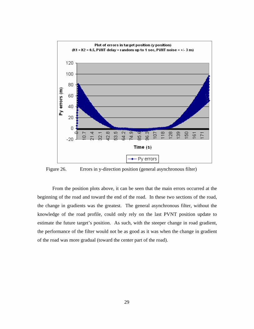
Figure 26. Errors in y-direction position (general asynchronous filter)
From the position plots above, it can be seen that the main errors occurred at the
beginning of the road and toward the end of the road. In these two sections of the road,
the change in gradients was the greatest. The general asynchronous filter, without the
knowledge of the road profile, could only rely on the last PVNT position update to
estimate the future target’s position. As such, with the steeper change in road gradient,
the performance of the filter would not be as good as it was when the change in gradient
of the road was more gradual (toward the center part of the road).
30
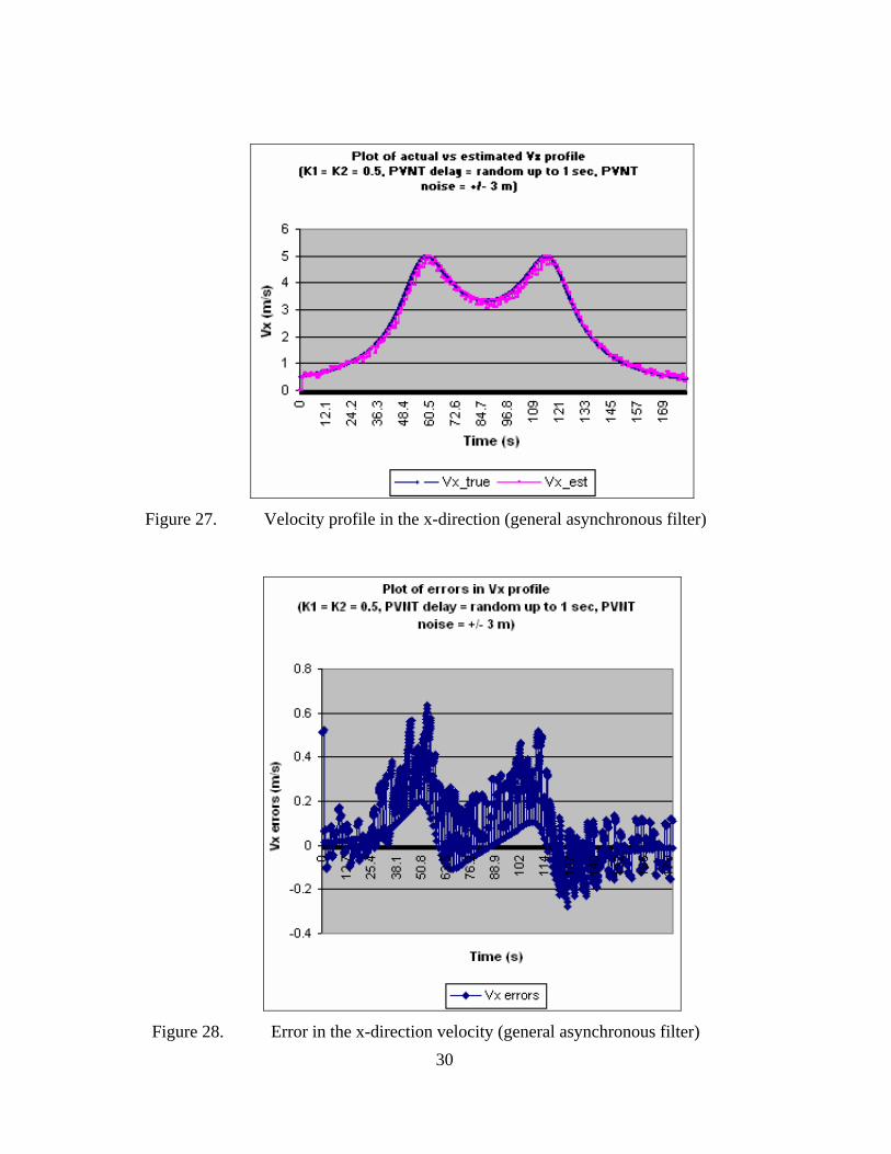
Figure 27. Velocity profile in the x-direction (general asynchronous filter)
Figure 28. Error in the x-direction velocity (general asynchronous filter)

31
Figure 29. Velocity profile in the y-direction (general asynchronous filter)
Figure 30. Error in the y-direction velocity (general asynchronous filter)

32
From the velocity plots above, the major velocity errors occurred when the
change in gradient was the highest. The prediction of the target’s velocity was similar to
its position estimation and the errors generated were also similar when there was a large
change in gradient of the profiles.
E. ROAD FOLLOWING ASYNCHRONOUS FILTER PERFORMANCE The road following asynchronous filter was run with the following parameters:
K1 = K2 = 0.5, PVNT delay = random up to 1 second, PVNT noise = +/- 3 meters. The
plots for the true and estimated velocity and position were plotted below. The rms errors
were also plotted.
Figure 31. Actual vs Estimated target position (road following asynchronous filter)

33
Figure 32. Errors in x-direction position (road following asynchronous filter)
Figure 33. Expanded plot for errors in x-direction position (road following asynchronous
filter)
34
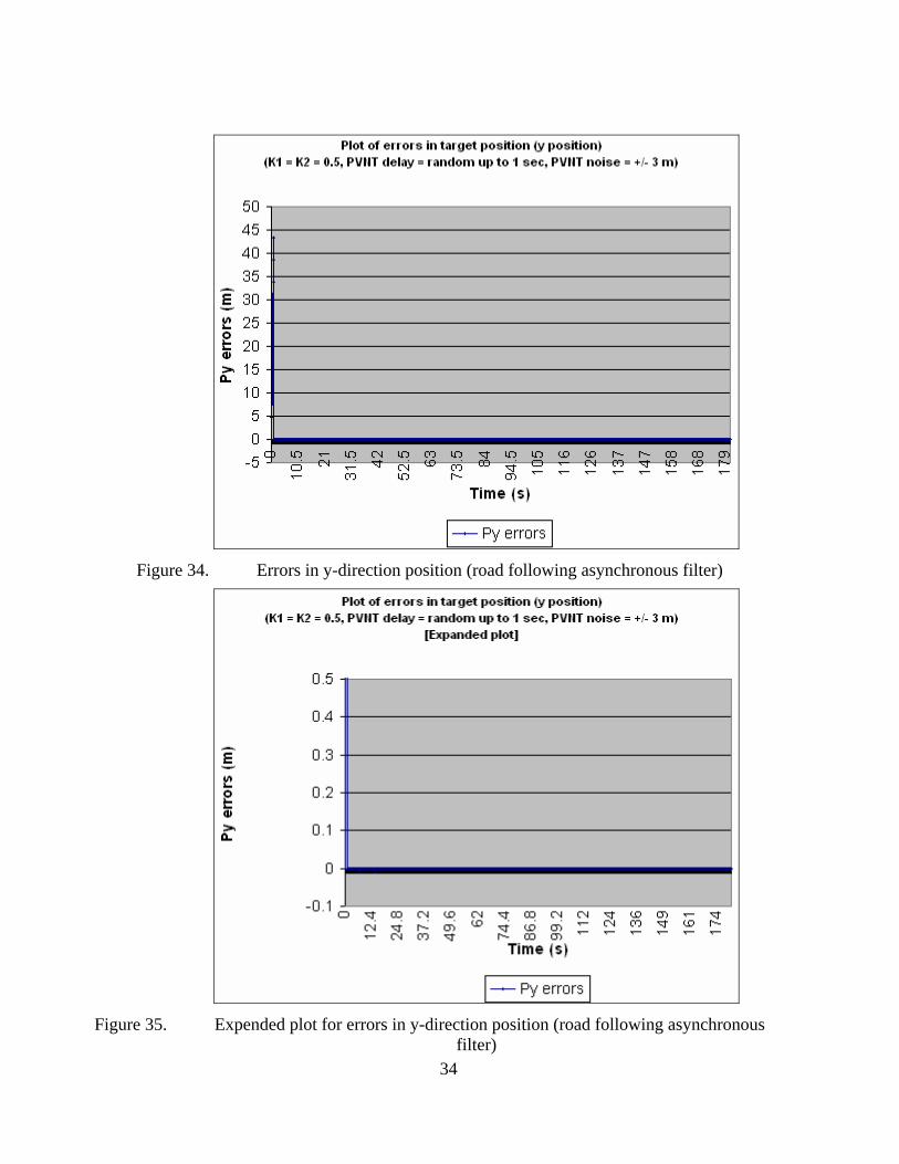
Figure 34. Errors in y-direction position (road following asynchronous filter)
Figure 35. Expended plot for errors in y-direction position (road following asynchronous
filter)

35
Based on the parameters specified for the simulation, the road following
asynchronous filter was able to provide very accurate position estimation. Both the x and
y direction errors were close to zero. This road following asynchronous filter showed a
vast improvement as compared to the general asynchronous filter. The knowledge of the
road profile allowed the optimization routine to further reduce the error that the PVNT
position estimate provided. The filter was able to integrate along the road provided and
gave very accurate target position estimation.
Figure 36. Velocity profile in the x-direction (road following asynchronous filter)

36
Figure 37. Error in the x-direction velocity (road following asynchronous filter)
Figure 38. Velocity profile in the y-direction (road following asynchronous filter)

37
Figure 39. Error in the y-direction velocity (road following asynchronous filter)
The target’s velocity estimation was very accurate using the road following
asynchronous filter. The filter was able to use the derivative of the path length (i.e.,
speed) to estimate the target’s velocity. Due to the accuracy provided by the
minimization routine in obtaining the path length, its derivative yields accurate velocity
estimation.

38
THIS PAGE INTENTIONALLY LEFT BLANK
39
VII. CONCLUSION AND RECOMMENDATION
A. CONCLUSION The task of designing an asynchronous filter was achieved in this thesis. The
asynchronous filter was able to use the delayed PVNT target position updates that arrived
about 1 to 10 seconds later to refine the target’s motion estimation. This simple filter has
shown its capability to estimate target motion in simulation. Furthermore, the general
asynchronous filter was modified to allow the incorporation of a road model. This
allowed a better prediction of target motion as the target’s motion is expected to be along
the road that it is traveling on. In simulation, it was shown that this modified filter could
estimate the target’s velocity and position very accurately.
B. RECOMMENDATION The new asynchronous filter worked well in simulation. In the future, this filter
could be incorporated in the hardware and be bench-tested. Further test in actual SUAV
flight could be conducted once bench testing has shown promising results.
The asynchronous filter could also be combined with the current non-linear filter
so that the two complement each other during target motion estimation. The advantage
of the asynchronous filter is in its ability to use the delayed but more accurate PVNT
update to provide a better target velocity and position estimation at current time. This
information could be used to re-initialize the nonlinear filter to enhance its performance
such that the current 10 – 20 m accuracy could be reduced.

40
THIS PAGE INTENTIONALLY LEFT BLANK
41
LIST OF REFERENCES
1. Khakimbayev, Jasur S. Development of Integrated 3D Terrain Maps for Unmanned Aerial Vehicle (UAV) Flight and Mission Control Support System (FMCSS). Master’s Thesis, Naval Postgraduate School, Monterey, California, 2006.
2. PerceptiVU, Inc. Retrieved November 17, 2006 from http://www.Perspective.com.
3. Honarbacht, A., Boschen, F., Kummert, A., & Harle, N. Synchronization of distributed simulations – a Kalman filter approach. Proceedings of the IEEE International Symposium on Circuits and Systems (ISCAS). Volume IV., Phoenix, Arizona, USA (2002), 469-472.
4. Kummert, A., & Honarbacht. A. State estimation of motion models based on asynchronous and non-equidistant measurement updates. Proceedings of the 8th IEEE International Conference on Methods and Models in Automation and Robotics (MMAR), Szczecin, Poland (2002), 55-60.
5. Drolet, L., Michaud, F., & Cote, J. Adaptable Sensor Fusion Using Multiple Kalman Filters. Proceedings of the 2000 IEEE/RSJ International Conference on Intelligence Robots and Systems. Volume 2., Takamatsu, Japan (2000), 1434-1439.
6. Dobrokhodov, Vladimir. N., Kaminer, Isaac. I., Jones, Kevin. D., & Ghabcheloo, R. Vision-Based Tracking and Motion Estimation for Moving targets using Small UAVs. Proceedings of the 2006 American Control Conference, Minneapolis, Minnesota, USA, June 14-16, 2006, 1428-1433.

42
THIS PAGE INTENTIONALLY LEFT BLANK

43
INITIAL DISTRIBUTION LIST
1. Defense Technical Information Center Ft. Belvoir, Virginia
2. Dudley Knox Library Naval Postgraduate School Monterey, California
3. Prof Anthony Healey Chairman, Department of Mechanical and Astronautical Engineering Naval Postgraduate School Monterey, California
4. Prof Isaac Kaminer Naval Postgraduate School Monterey, California
5. Dr Vladimir Dobrokhodov Naval Postgraduate School Monterey, California
6. Prof Yeo Tat Soon Director, Temasek Defence Systems Institute National University of Singapore Singapore
7. Ms Tan Lai Poh Temasek Defence Systems Institute National University of Singapore Singapore


