Incompressible Fluid Flow. References Required Principles of Naval Engineering – (pg. 35-59)...
63
Incompressible Fluid Flow
-
Upload
francis-harrell -
Category
Documents
-
view
218 -
download
1
Transcript of Incompressible Fluid Flow. References Required Principles of Naval Engineering – (pg. 35-59)...

Incompressible Fluid Flow

References
Required• Principles of Naval Engineering
– (pg. 35-59)
Optional• Introduction to Naval Engineering
– (pg. 19-22 & 477-501)

Objectives
– Comprehend the various forms of head to fluid dynamics.
– Apply Pascal’s Principle, the principle of Conservation of Mass, and Bernoulli’s Equation to fluid dynamics.
– Comprehend the modes of fluid flow including the factors determining the mode, the associated velocity/temperature profiles, the effects on heat transfer rates, and the desirable qualities of each.

Objectives
– Comprehend the operation and application of various pumps found in the propulsion plant.
– Comprehend the operation and application of centrifugal and axial fans.
– Comprehend the basic construction and application of valves used in the propulsion plant including methods for operating remotely.
– Know the schematic representations for valves and pumps used in the propulsion plant.
– Comprehend the principles of operation of various heat exchangers and their classification.

Pascal’s Principle• The force applied to a column of liquid is transmitted equally and
undiminished in all directions through the liquid and to the walls of its container.
=100 lbf
Find F2

Head (Pressure)
• Head is a surrogate term for pressure• The height of a column of flowing fluid that a
given pressure can support• Three types
– Static Head– Velocity Head– Friction Head

Static Head
• Head– The pressure
exerted by a column of fluid

Velocity Head
• The head necessary to impart velocity to a liquid
• Equivalent to the distance through which the liquid would have to fall to acquire the same velocity

Friction Head
• The pressure necessary to overcome friction• Also referred to as Head Loss• What are the sources of friction in a piping
system?

Friction Head
• Head loss in a straight run of piping given by Darcy’s Equation:
• Where:– D = piping diameter– L = piping length– F = empirically determined friction coefficient– v = fluid velocity

Friction Head
• Additional friction sources are introduced to the system by valves and fittings
• Head loss associated with these components is given by:
– k = experimentally determined coeffiecient

Fluid Flow Profiles
• Fluid flow in piping is affected by:– Piping diameter– Fluid viscosity– Fluid velocity– Relative piping roughness
• Fluid flows in two broad categories– Laminar – Turbulent

Flow Regimes
Laminar Flow
• Streamline or viscous flow• Layers of fluid flow over one
another with virtually no mixing
• Fluid particles move in definite and observable paths
• Parabolic flow profile
Turbulent Flow• Irregular particle movement• No observable paths or
layers• Relatively flat profile

Conservation of Mass
• Just as energy is conserved in the SFEE, mass is also conserved.
• Under steady state conditions, the mass entering a system equals the mass leaving the system.
Where:
Conservation of Mass
• The nozzle of a fire hose contracts from 2.5” in diameter to 0.5” in diameter. On average, the water traveling in the hose moves at 10 ft/sec.
• Find the exit velocity of the water.
D2D1V1
V2

Bernoulli’s Equation
• A rearrangement of the SFEE where– ∆u=0 – q=0
Velocity head
static head
Pressure head

Valves
• devices which control the amount and direction of fluid flow in piping systems
• Material is dictated by the system conditions:– High Pressure/Temperature Applications: Steel
Alloys– Low Pressure/Temperature Applications: Bronze,
Brass

Globe Valve
InletOutlet
Hand Wheel
Packing Gland Nut
Stem
Packing Gland Follower
BodyDisc
Seat
Bonnet

Types of Valves• Two basic groups:
– Stop valves - used to shut off or partially shut off the flow of fluid ( ex: globe, gate, plug, needle, butterfly)
– Check Valves - used to permit flow in only one direction (ex: ball-check, swing-check, lift-check)
• Special types:– Relief valves– Pressure-reducing valves– Remote-operated valves

Globe Valve
InletOutlet
Hand Wheel
Packing Gland Nut
Stem
Packing Gland Follower
BodyDisc
Seat
Bonnet

Globe Valve
http://www.youtube.com/watch?v=yTr4kpkHovg

Globe Valves
– Most common type of stop valve– Used in steam, air, water, & oil lines– Disc attached to valve stem rests against seat to
shut off flow of fluid– Adv: Good throttling (flow control) characteristics– Disadv: high head loss (flow resistance)

Gate Valve
InletOutlet
Body
Hand Wheel
Disc
Stem
Bonnet
Packing Gland Nut
Packing Gland Follower

Gate Valve
– Used when there must be straight-line flow of fluid w/ min. resistance
– Gate usually wedge-shaped or a vertical disc– Adv: minimal head loss when open, excellent stop
valve– Disadv: poor throttling characteristics, difficult to
open against a large differential pressure• Two types:
– Rising Stem– Non-rising Stem

Butterfly Valve
BallValve

Butterfly Valves• Butterfly Valves
– Used in water, fuel, and ventilation systems– Adv: light-weight, & quick-acting, low head loss– Disadv: poor throttling, poor seating
characteristics
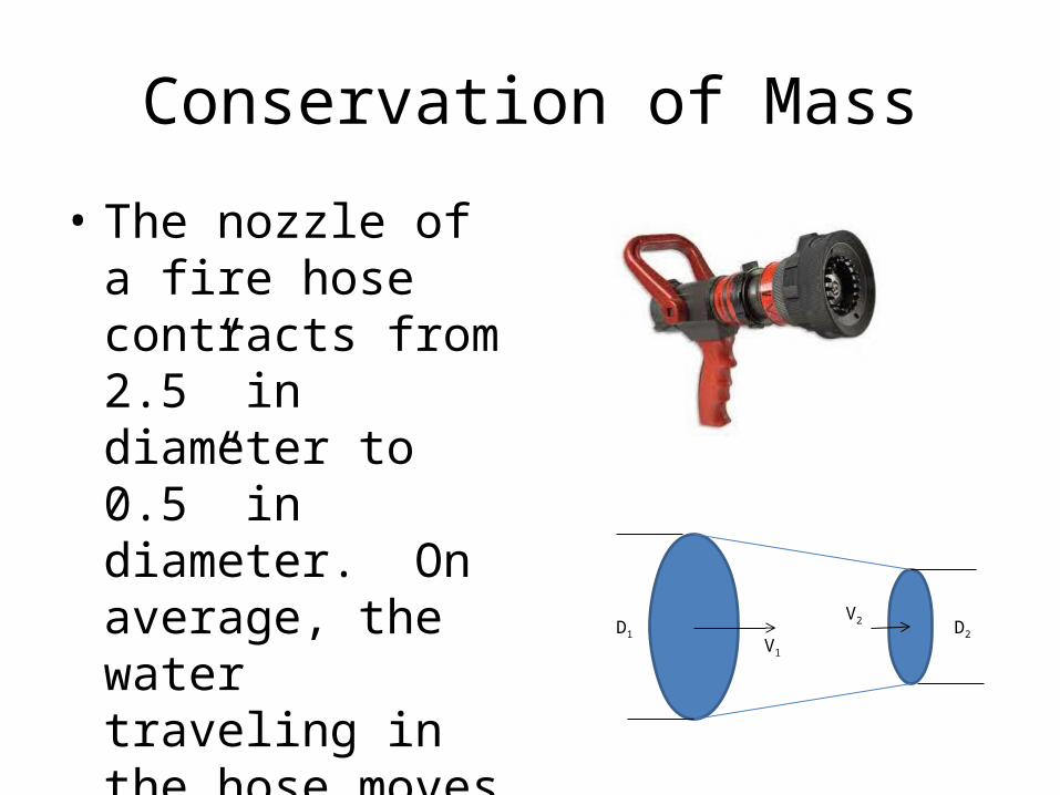
Ball Valves
• Ball Valves– Similar to butterfly valves– Normally found in seawater, sanitary, and
hydraulic systems– Adv: excellent seating characteristics– Disavd: zero throttling

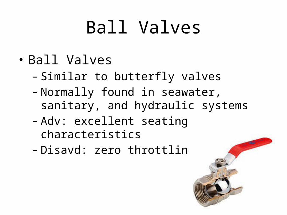
Check Valves
• Controls direction of flow• Operated by flow of fluid in pipe• Types:
– Swing check - disc moves through an arc– Lift check - disc moves up and down– Ball check - ball is located at end of stem and lifts
to allow flow
Swing-check Valve

Lift Check Valve

Ball Check Valve

Relief Valves• Used to protect piping
system from excessive pressure
• Opens automatically when fluid pressure becomes too high (pressure acts against spring pressure)
• Relieving pressure set by an adjusting screw

Pressure-reducing Valves
• Used to automatically provide a steady, lower pressure to a system from a higher pressure source
• Used in air, lube-oil, seawater, and other systems
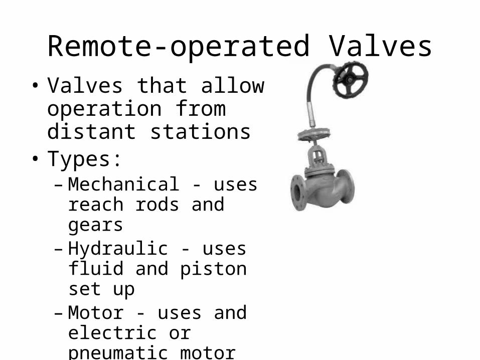
Remote-operated Valves• Valves that allow operation
from distant stations• Types:
– Mechanical - uses reach rods and gears
– Hydraulic - uses fluid and piston set up
– Motor - uses and electric or pneumatic motor
– Solenoid - uses coil and core mechanism to open or close on an electric signal

Remote Operators
• Mechanical

Remote Operators
• Hydraulic

Remote Operators
• Motor

Remote Operators
• Solenoid

Heat Exchangers(HX)• Definition: and device designed to allow the flow of
thermal energy (heat) from one fluid to another• Ships (and life in general) are filled with heat
exchangers. Examples??
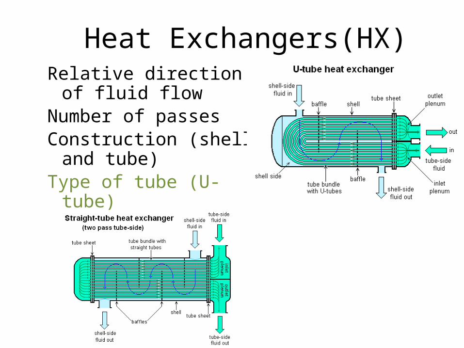
• Heat Exchangers are classified by:– Relative direction of fluid flow– Number of passes– Construction (shell and tube)– Type of tube (U-tube)
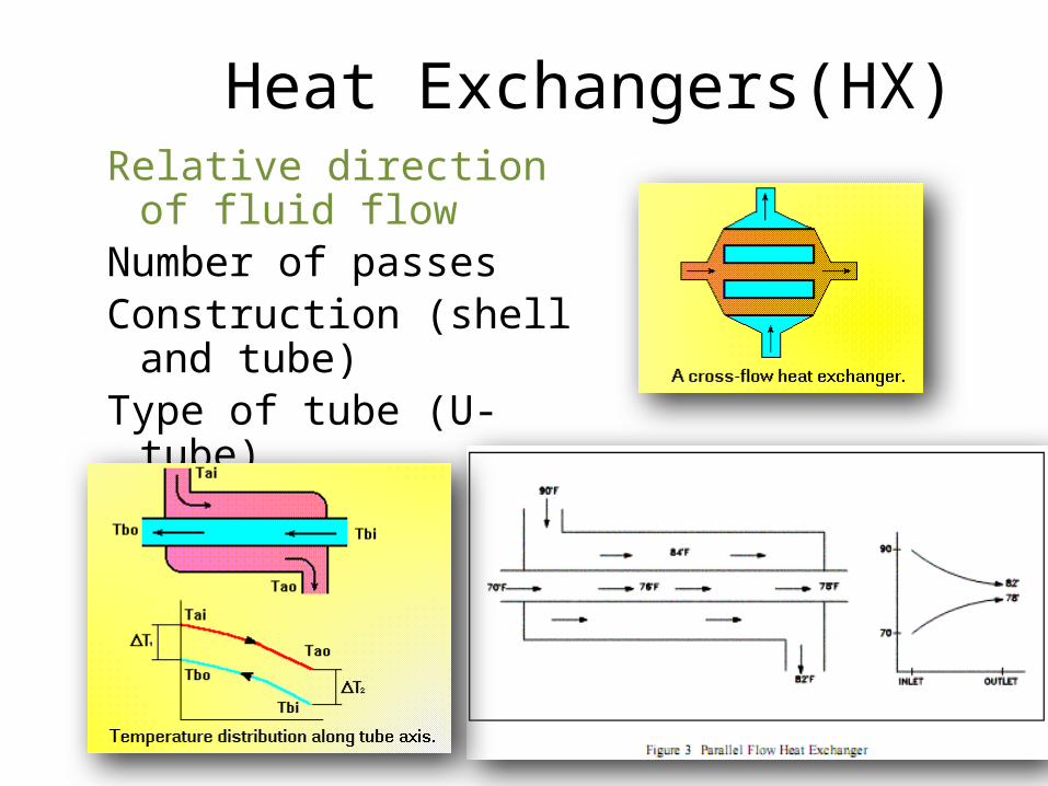
Heat Exchangers(HX)Relative direction of fluid
flowNumber of passesConstruction (shell and
tube)Type of tube (U-tube)
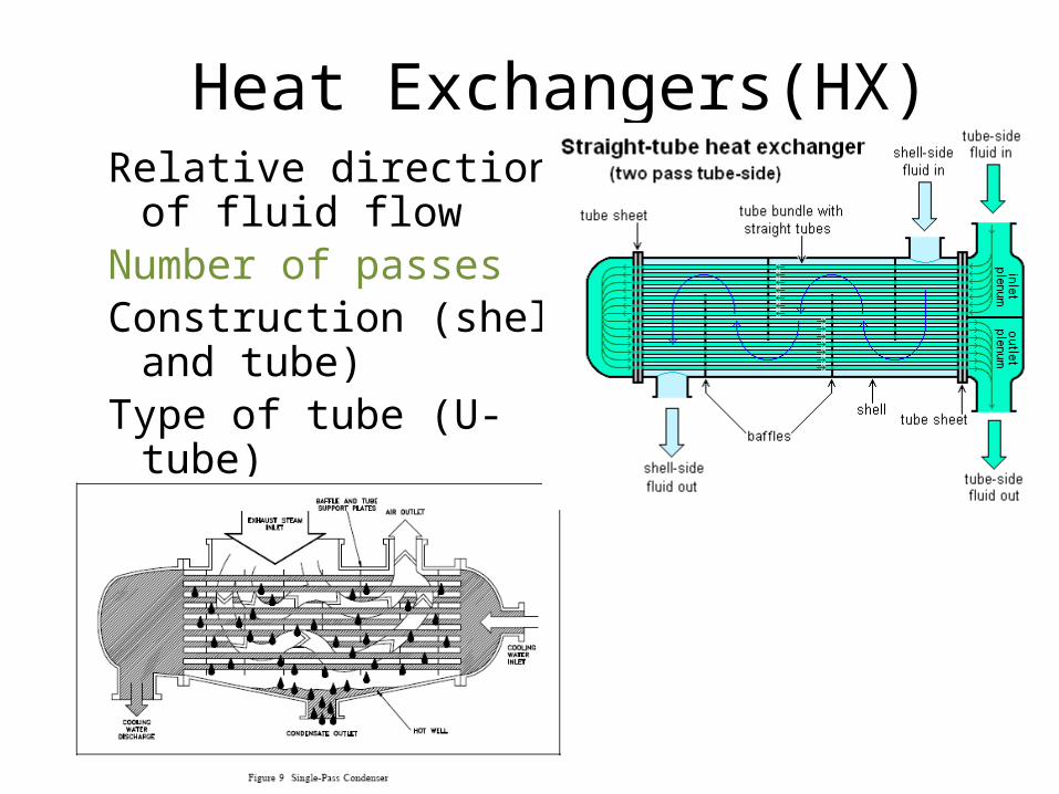
Heat Exchangers(HX)Relative direction of fluid
flowNumber of passesConstruction (shell and
tube)Type of tube (U-tube)

Heat Exchangers(HX)Relative direction of fluid
flowNumber of passesConstruction (shell and
tube)Type of tube (U-tube)
Heat Exchangers(HX)Relative direction of fluid
flowNumber of passesConstruction (shell and
tube)Type of tube (U-tube)
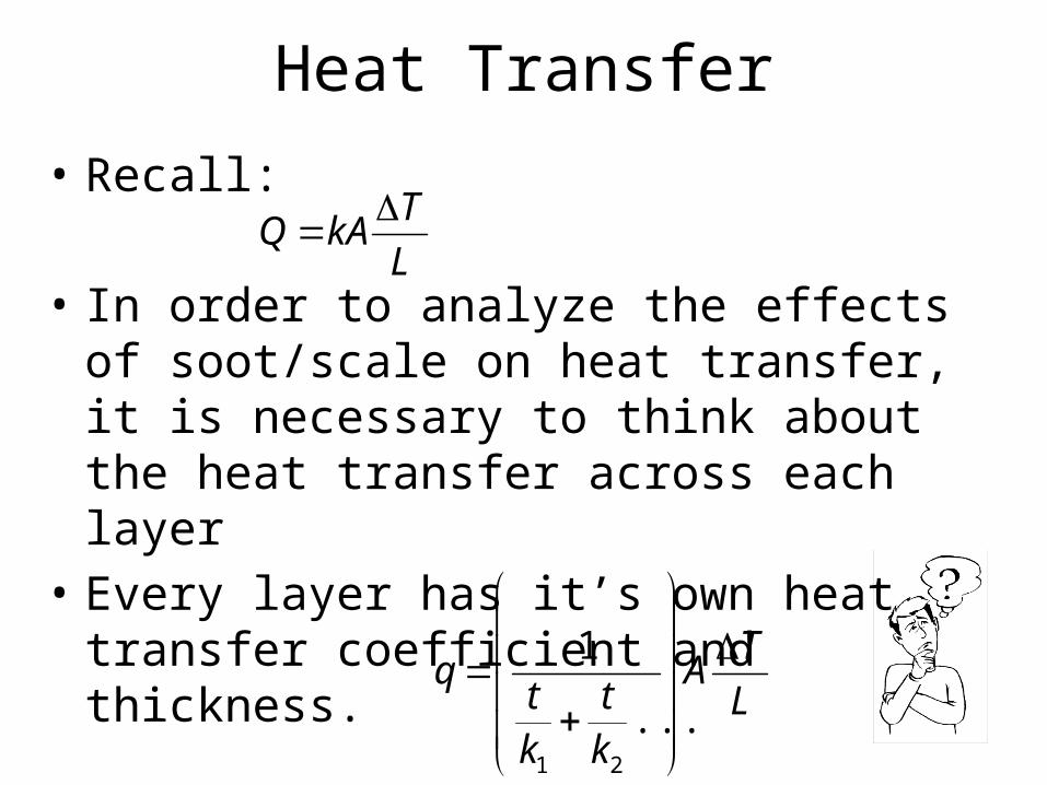
Heat Transfer
• Recall:
• In order to analyze the effects of soot/scale on heat transfer, it is necessary to think about the heat transfer across each layer
• Every layer has it’s own heat transfer coefficient and thickness.
L
TkAQ
L
TA
kt
kt
q
...
1
21

Pumps
Pumps• Device that adds energy to a fluid in order
to:– Supply pressure head– Overcome head loss– Provide sufficient flow– Raise the height of the fluid
• Accomplished by– Pushing– Pulling– Throwing– Combination of the three

Components of Pumps
• Drive mechanism (steam, electric, gear)• Pump shaft• Impeller or piston• Casing

Positive Displacement Pump
Positive Displacement Pump
• Used in systems that employ a viscous working substance (like oil) or high pressure applications such as lubrication/hydraulic systems
• Advantage: constant discharge volume, self priming
• Disadvantage: pulsating discharge, lower flow rates compared to centrifugal pumps

Pumps
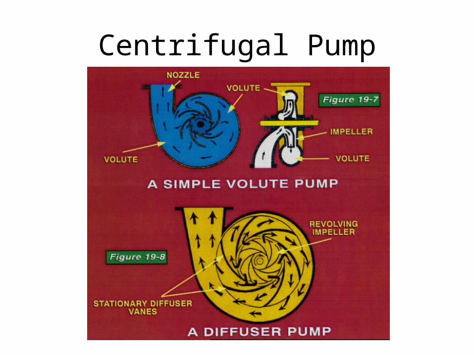
• Non-positive Displacement: volume of fluid is dependent on static head/pressure– Centrifugal: impeller inside a case (called volute).
Impeller is a disc w/ curved vanes mounted radially (like a paddle wheel)
• Suction is the Eye -> fluid accelerated as it travels outward & then enters volute
– Propeller: uses prop inside casing to move fluid -> not used much in Navy
Centrifugal Pump

Centrifugal Pump

Pumps
• Jet pumps: – Bernoulli’s principle and no moving parts– Velocity Head vs. Pressure head
hin + vin2/2 = hout + vout
2/2

Pump Characteristic Curves
• Pump Parameters:– N = pump speed, RPM– V = volumetric flow rate, GPM– Hp = pump head (discharge pressure), psig– P = power required, Hp
• Centrifugal Pump Laws– V a N– Hp a N2
– W a N3

Positive Displacement Pumps
Hp
GPM
N1 N2
N2 = ____

Centrifugal Pumps
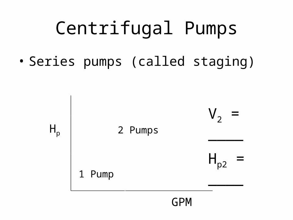
Centrifugal Pumps
• Series pumps (called staging)
Hp
GPM
V2 = ____
Hp2 = ____2 Pumps
1 Pump

Net Positive Suction Head
• Def’n: that pressure required at the suction of a pump to prevent cavitation
• So what is cavitation? - the formation of bubbles due to low
pressure area and the subsequent collapse upon migration to a high pressure area
• Cavitation causes noise and damage
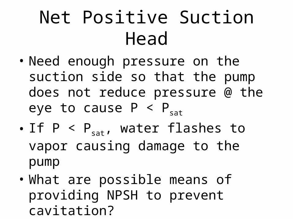
Net Positive Suction Head
• Need enough pressure on the suction side so that the pump does not reduce pressure @ the eye to cause P < Psat
• If P < Psat, water flashes to vapor causing damage to the pump
• What are possible means of providing NPSH to prevent cavitation?

Take Aways
• Describe the two basic groups of valves. Give examples of each and any associated advantages/disadvantages
• Properly label a drawing of a globe/gate valve indicating the following:
- Valve body - Packing- Disc - Packing gland/nut- Seat - Stem- Bonnet - Hand wheel
• Describe the purpose of a relief valve and pressure reducing valve• Describe the various methods of remotely operating valves• Describe the purpose of a pump. Describe the types of pumps covered in
lecture (positive displacement, centrifugal, jet pump).
Take Aways• Describe how volumetric flow rate, pump head and power vary with pump speed• Describe how the above parameters are affected by various pump combinations
(series, parallel operation)• List and describe the two types of fans.• Apply Pascal’s Principle to specific situations• Apply Bernoulli’s Equation to specific situations.

Homework
• 1.10• 1.16• 1.17• 2.1• 2.9

Questions?
Questions?