INCH-POUND RR-C-271G CHAINS AND ATTACHMENTS,
61
Comments, suggestions, or questions on this document should be addressed to DLA Aviation, VEB, 8000 Jefferson Davis Highway, Richmond, VA 23297-5616 or e-mailed to [email protected]. Since contact information can change, you may want to verify the currency of this address information using the ASSIST database at https://assist.dla.mil. AMSC N/A FSC 4010 INCH-POUND RR-C-271G 28 March 2016 SUPERSEDING RR-C-271F 5 July 2011 FEDERAL SPECIFICATION CHAINS AND ATTACHMENTS, CARBON AND ALLOY STEEL The General Services Administration has authorized the use of this federal specification by all federal agencies. 1. SCOPE AND CLASSIFICATION 1.1 Scope. This specification covers carbon and alloy steel chain of commercial quality together with the attachments most commonly used with this chain. 1.1.1 Federal specification coverage. Federal specifications do not include all types, grades, classes, and styles of the commodities indicated by the title of the specification, or which are commercially available, but are intended to cover the types that are suitable for Federal Government requirements. 1.2 Classification. The welded and weldless chain and attachments are of the following types, classes, grades and styles as specified below. 1.2.1 Chain types. The types, classes, grades and styles of welded and weldless chain are as follows (see 6.2): Type I - Chain, welded steel (PIN code -C1) Class 1 - Alloy chain (overhead lift) Grade A – 80 grade Grade B – 100 grade Source: https://assist.dla.mil -- Downloaded: 2016-04-21T14:54Z Check the source to verify that this is the current version before use.
Transcript of INCH-POUND RR-C-271G CHAINS AND ATTACHMENTS,
Comments, suggestions, or questions on this document should be addressed to DLA Aviation,
VEB, 8000 Jefferson Davis Highway, Richmond, VA 23297-5616 or e-mailed to
[email protected]. Since contact information can change, you may want to verify the
currency of this address information using the ASSIST database at https://assist.dla.mil.
AMSC N/A FSC 4010
INCH-POUND
RR-C-271G
28 March 2016
SUPERSEDING
RR-C-271F
5 July 2011
FEDERAL SPECIFICATION
CHAINS AND ATTACHMENTS,
CARBON AND ALLOY STEEL
The General Services Administration has authorized the use of this federal specification
by all federal agencies.
1. SCOPE AND CLASSIFICATION
1.1 Scope. This specification covers carbon and alloy steel chain of commercial quality together with the attachments most commonly used with this chain. 1.1.1 Federal specification coverage. Federal specifications do not include all types, grades, classes, and styles of the commodities indicated by the title of the specification, or which are commercially available, but are intended to cover the types that are suitable for Federal Government requirements. 1.2 Classification. The welded and weldless chain and attachments are of the following types, classes, grades and styles as specified below. 1.2.1 Chain types. The types, classes, grades and styles of welded and weldless chain are as follows (see 6.2): Type I - Chain, welded steel (PIN code -C1) Class 1 - Alloy chain (overhead lift) Grade A – 80 grade Grade B – 100 grade
Source: https://assist.dla.mil -- Downloaded: 2016-04-21T14:54ZCheck the source to verify that this is the current version before use.

RR-C-271G
2
Class 2 - High-test chain (grade 43) Class 3 - Transport chain (grade 70) Class 4 - Proof-coil chain (grade 30) Class 5 - Twist-link chain Style 1 - Long-link pattern (coil) Style 2 - Short-link pattern (machine) Type II - Chain, weldless (PIN code -C2) Class 1 - Single-loop pattern chain Class 2 - Double-loop pattern chain Class 3 - Sash chain Class 4 - Flat-link chain Class 5 - Bead chain Class 6 - Plumber's chain Class 7 - Single-jack chain Class 8 - Double-jack chain Class 9 - Ladder chain Class 10 - Register chain Class 11 - Mechanical communication chain 1.2.2 Attachment types. Attachment types, grades, and classes are as follows (see 6.2):
Type II - Connecting links (PIN code -A2)
Type III - Lap links (PIN code -A3)
Type IVA - Anchor shackles (PIN code -A41)
Grade A - Regular
Class 1 - Round pin and cotter
Class 2 - Screw pin
Class 3 - Bolt, nut and cotter
Grade B - High strength
Class 1 - Round pin and cotter
Class 2 - Screw pin
Class 3 - Bolt, nut and cotter
Source: https://assist.dla.mil -- Downloaded: 2016-04-21T14:54ZCheck the source to verify that this is the current version before use.

RR-C-271G
3
Type IVB - Chain shackles (PIN code -A42)
Grade A - Regular
Class 1 - Round pin and cotter
Class 2 - Screw pin
Class 3 - Bolt, nut and cotter
Grade B - High strength
Class 1 - Round pin and cotter
Class 2 - Screw pin
Class 3 - Bolt, nut and cotter
Type V – Hooks (PIN code -A5)
Class 1 – Alloy hooks
Grade A – Grade 80
Style 2E – Eye Grab hook (see 6.1.4.2)
Style 2C – Clevis Grab hook (see 6.1.4.2)
Style 3E – Eye Sling hook (see 6.1.4.1)
Style 3C – Clevis Sling hook (see 6.1.4.1)
Grade B – Grade 100
Style 2E – Eye Grab hook (see 6.1.4.2)
Style 2C – Clevis Grab hook (see 6.1.4.2)
Style 3E – Eye Sling hook (see 6.1.4.1)
Style 3C – Clevis Sling hook (see 6.1.4.1)
Class 2 – High-test hooks (grade 43)
Style 1E – Eye Slip hook (see 6.1.4.1)
Style 1C – Clevis Slip hook (see 6.1.4.1)
Style 2E – Eye Grab hook (see 6.1.4.2)
Style 2C – Clevis Grab hook (see 6.1.4.2)
Class 3 – Transport hooks (grade 70)
Style 1E – Eye Slip hook (see 6.1.4.1)
Style 1C – Clevis Slip hook (see 6.1.4.1)
Style 2E – Eye Grab hook (see 6.1.4.2)
Style 2C – Clevis Grab hook (see 6.1.4.2)
Class 4 – Proof-coil hooks (grade 30)
Style 1E – Eye Slip hook (see 6.1.4.1)
Style 1C – Clevis Slip hook (see 6.1.4.1)
Style 2E – Eye Grab hook (see 6.1.4.2)
Style 2C – Clevis Grab hook (see 6.1.4.2)
Source: https://assist.dla.mil -- Downloaded: 2016-04-21T14:54ZCheck the source to verify that this is the current version before use.

RR-C-271G
4
Class 5 – Hoist hooks
Style 4E – Eye Hoist hook (see 6.1.4.3)
Style 4S – Swivel Eye Hoist hooks (see 6.1.4.3)
Class 6 – Barrel hooks
Type VI – Rings (PIN code -A6)
Type VII – Swivels (PIN code-A7)
Class 1 - Chain swivels
Class 2 - Eye and eye swivels
Class 3 - Jaw and eye swivels
Type IX - Bead chain fasteners (PIN code -A9)
Type X - Bead chain couplings (PIN code -A10)
Type XI - Bead chain insulating couplings (PIN code -A11)
Type XIII - Pear-shaped links (PIN code -A13)
Type XIV - Mechanical coupling links (PIN code -A14)
Grade A – 80 grade
Grade B – 100 grade
Type XV - End links (PIN code -A15)
Type XVI - Chain master links (PIN code -A16)
1.3 Part identification number (PIN). There are separate PIN configurations for each chain and
chain attachment type. The complete PIN configuration is given in appendix A.
2. APPLICABLE DOCUMENTS
2.1 Government publications. The issues of the following documents, in effect on the date of
invitation for bids or request for proposal, form a part of this specification to the extent specified
herein.
Federal Standards
FED-STD-123 - Marking for Shipment (Civil Agencies)
Source: https://assist.dla.mil -- Downloaded: 2016-04-21T14:54ZCheck the source to verify that this is the current version before use.

RR-C-271G
5
Military Standard
MIL-STD-1916 - DoD Preferred Methods for Acceptance of Product
MIL-STD-2073-1 - Standard Practice for Military Packaging
(Copies of these documents are available online at http://quicksearch.dla.mil)
Federal Acquisition Regulation (FAR)
Subpart 23.4 - Use of Recovered Materials and Biobased Products
(Copies of the FAR may be obtained online at https://www.acquisition.gov.)
2.2 Other publications. The following documents form a part of this specification to the extent
specified herein. Unless a specific issue is identified, the issue in effect on the date of invitation
for bids or request for proposal shall apply.
American Society for Quality (ASQ)
ASQ H1331 - Zero Acceptance Number Sampling Plans
(Copies of this document are available online at http://www.asq.org/.)
ASME
ASME B1.1 - Unified Inch Screw Threads (UN and UNR Thread
Forms)
(Copies of this document are available online at http://www.asme.org/.)
ASTM International
ASTM A143/A143M - Standard Practice for Safeguarding Against
Embrittlement of Hot-Dip Galvanized Structural
Steel Products and Procedure for Detecting
Embrittlement
ASTM A153/A153M - Standard Specification for Zinc Coating (Hot-Dip)
on Iron and Steel Hardware
ASTM A304 - Standard Specification for Carbon and Alloy Steel
Bars Subject to End-Quench Hardenability
Requirements
ASTM A322 - Standard Specification for Steel Bars, Alloy,
Standard Grades
ASTM A391/A391M - Standard Specification for Grade 80 Alloy Steel
Chain
ASTM A413/A413M - Standard Specification for Carbon Steel Chain
ASTM A466/A466M - Standard Specification for Weldless Chain
Source: https://assist.dla.mil -- Downloaded: 2016-04-21T14:54ZCheck the source to verify that this is the current version before use.

RR-C-271G
6
ASTM International (continued)
ASTM A467/A467M - Standard Specification for Machine and Coil Chain
ASTM A510/A510M - Standard Specification for General Requirements
for Wire Rods and Coarse Round Wire, Carbon
Steel
ASTM A576 - Standard Specification for Steel Bars, Carbon, Hot-
Wrought, Special Quality
ASTM A752 - Standard Specification for General Requirements
for Wire Rods and Coarse Round Wire, Alloy Steel
ASTM A909/A909M - Standard Specification for Steel Forgings,
Microalloy, for General Industrial Use
ASTM A920/A920M - Standard Specification for Steel Bars, Microalloy,
Hot-Wrought, Special Quality, Mechanical
Properties
ASTM A921/A921M - Standard Specification for Steel Bars, Microalloy,
Hot-Wrought, Special Quality, for Subsequent Hot
Forging
ASTM A952/A952M - Standard Specification for Forged Grade 80 and
Grade 100 Steel Lifting Components and Welded
Attachment Links
ASTM A973/A973M - Standard Specification for Grade 100 Alloy Steel
Chain
ASTM B633 - Standard Specification for Electrodeposited
Coatings of Zinc on Iron and Steel
ASTM B695 - Standard Specification for Coatings of Zinc
Mechanically Deposited on Iron and Steel
ASTM D3951 - Standard Practice for Commercial Packaging
(Copies of this document are available online at http://www.astm.org/.)
2.3 Order of precedence. Unless otherwise noted herein or in the contract, in the event of a
conflict between the text of this document and the references cited herein, the text of this
document takes precedence. Nothing in this document, however, supersedes applicable laws and
regulations unless a specific exemption has been obtained.
3. REQUIREMENTS
3.1 Material.
3.1.1 Applicable materials. All items specified in this document are listed in Appendix B with
their applicable materials.
3.1.1.1 General. Unless otherwise specified, the material for type I chain and the indicated
attachments and attachment parts shall conform to the chemical composition shown in table I.
Source: https://assist.dla.mil -- Downloaded: 2016-04-21T14:54ZCheck the source to verify that this is the current version before use.

RR-C-271G
7
TABLE I. Chemical composition.
Element Maximum percent
Type I chain and type II, III, V, VI, VII,
XIII, XIV, and XV attachments and
attachment parts:
Carbon
Phosphorus
Sulfur
Silicon
0.37 1
0.05
0.05
0.35
Type IV shackles:
Carbon
Phosphorus
Sulfur
Silicon
0.45
0.04
0.045
0.35 1
Steel with carbon 0.50 (maximum percent) is permitted for attachments or attachment
parts provided the fabrication is done without welding.
3.1.2 Recovered materials. The offeror/contractor is encouraged to use recovered materials to
the maximum extent practicable, in accordance with paragraph 23.403 of the Federal Acquisition
Regulation (FAR).
3.2 Finish.
3.2.1 General. The finish for chain and attachments shall be as specified (see 6.2). The
following finishes for chain and attachments are typical.
(a) Self-colored (chain uncoated, attachments cleaned and uncoated) (PIN code S)
(b) Bright finish (chain cleaned) (PIN code B)
(c) Zinc-coated (PIN code Z)
(d) Painted (PIN code P)
3.2.1.1 Type I, chain, welded steel.
3.2.1.1.1 Type I, class 1 chain. The finish for type I, class 1 shall be bright finish or painted.
3.2.1.1.2 Type I, class 2, 3, 4 and 5 chain. Unless otherwise specified (see 6.2), the finish for
type I, class 2, 3, 4, and 5 shall be self-colored, bright finish, zinc coated or painted.
3.2.1.2 Type II, chain, weldless. Unless otherwise specified (see 6.2), the chain shall be zinc
coated or self-colored.
3.2.1.3 Attachments. Unless otherwise specified (see 6.2), attachments shall be self-colored,
painted or zinc coated.
Source: https://assist.dla.mil -- Downloaded: 2016-04-21T14:54ZCheck the source to verify that this is the current version before use.

RR-C-271G
8
3.2.1.4 Zinc coating. When zinc coating is specified, the coating may be applied by the hot-dip
(galvanizing) process, by the electrodeposition process, or by the mechanically deposited coating
process at the contractor's option. If the hot-dip process is used, the coating shall be applied in
accordance with ASTM A153/A153M, class B3; if the electrodeposition process is used, it shall
be in accordance with ASTM B633, type II, class Fe/Zn 12; and if the mechanically deposited
coating process is used, it shall be in accordance with ASTM B695, type II, class 12. When the
electrodeposition process is used, the coating shall be done on screw parts after threading and
tapping is completed. When the hot-dip process is used, internal threads may be tapped or
retapped after galvanizing. Zinc coating shall be adherent, smooth, and free from injurious
defects.
3.2.1.4.1 Embrittlement. When zinc coating of alloy steel is specified, the safeguarding against
embrittlement and the procedure for detecting embrittlement shall be in accordance with
ASTM A143/A143M.
3.2.1.4.2 Paint over galvanizing. On attachments, paint may be applied over galvanizing at the
option of the manufacturer. All other requirements of 3.2.1.4 shall be met.
3.3 Detail requirements - chain. The figures herein are descriptive, not restrictive, and are not
intended to preclude the purchase of chain otherwise in accordance with this specification.
3.3.1 Type I, chain, welded steel.
3.3.1.1 Type I, class 1, welded steel alloy chain. The steel alloy chain shall be similar to figure 1
and shall be in accordance with ASTM A391/A391M for grade 80 or ASTM A973/A973M for
grade 100.
FIGURE 1. Type I, class 1, 2, 3, and 4 chain.
3.3.1.2 Type I, class 2, welded steel high-test chain. The high test chain shall be similar to
figure 1 and shall be in accordance with ASTM A413/A413M, grade 43.
3.3.1.3 Type I, class 3, transport chain. The transport chain shall be similar to figure 1 and shall
be in accordance with ASTM A413/A413M, grade 70.
3.3.1.4 Type I, class 4, welded steel proof-coil chain. The proof-coil chain shall be similar to
figure 1 and shall be in accordance with ASTM A413/A413M, grade 30.
3.3.1.5 Type I, class 5, style 1, welded steel twist-link chain, long-link pattern (coil). The long-
link chain shall be similar to figure 2 and shall conform to the dimensions and physical
requirements specified in ASTM A467/A467M, class CT.
Source: https://assist.dla.mil -- Downloaded: 2016-04-21T14:54ZCheck the source to verify that this is the current version before use.

RR-C-271G
9
FIGURE 2. Type I, class 5, style 1, welded steel twist-link chain, long-link pattern (coil).
3.3.1.5.1 PIN designation for coil style twist-link chain. The PIN size designation for coil style
twist-link chain shall be 01 to 04 for sizes 1 to 4 and 10 to 50 for trade sizes 1/0 to 5/0.
3.3.1.6 Type I, class 5, style 2, welded steel twist-link chain, short-link pattern (machine). The
short-link chain shall be similar to figure 3 and shall be in accordance with the dimensions and
physical requirements as specified in ASTM A467/A467M, class MT.
FIGURE 3. Type I, class 5, style 2, welded steel twist-link chain, short-link pattern (machine).
3.3.1.6.1 PIN designation for machine style twist-link chain. The PIN size designation for
machine style twist-link chain shall be 01 to 04 for sizes 1 to 4 and 10 to 50 for trade sizes 1/0 to
5/0.
3.3.2 Type II, chain, weldless.
3.3.2.1 Class 1, single-loop pattern chain. The single-loop pattern chain shall be similar to
figure 4 and shall be in accordance with ASTM A466/A466M, class SL.
FIGURE 4. Type II, class 1, weldless, single-loop pattern chain.
3.3.2.1.1 PIN size numbers for single-loop chain. The PIN size numbers for single-loop chain
shall be 02 for trade size 2 and 10 through 50 for trade sizes 1/0 through 5/0.
3.3.2.2 Class 2, double-loop pattern chain. The double-loop pattern chain shall be similar to
figure 5 and shall be in accordance with ASTM A466/A466M, class DL.
FIGURE 5. Type II, class 2, weldless double-loop pattern chain.
Source: https://assist.dla.mil -- Downloaded: 2016-04-21T14:54ZCheck the source to verify that this is the current version before use.

RR-C-271G
10
3.3.2.2.1 PIN size numbers for double-loop chain. The PIN size numbers for douple-loop chain
shall be 05 through 01 for trade size 5 through 1 and 10 through 80 for trade sizes 1/0 through
8/0 and shall include the L designation when required.
3.3.2.3 Class 3, sash chain. The sash chain shall be similar to figure 6 and shall be in
accordance with ASTM A466/A466M, class SH.
FIGURE 6. Type II, class 3, weldless sash chain.
3.3.2.3.1 PIN size numbers for sash chain. The PIN size numbers for sash chain shall be the
same as the trade size except a zero will be added before any single digit to create a 2 digit size
number.
3.3.2.4 Class 4, flat-link chain. The flat-link chain shall be similar to figure 7 and shall be in
accordance with the requirements as shown in table II.
FIGURE 7. Type II, class 4, weldless flat-link chain.
TABLE II. Type II, class 4, weldless flat-link chain.
Nominal
metal
thickness
(inch)
Number of
links per
foot
(approx)
Weight per 100 feet
(approx) (pounds)
Breaking load (min) 1
(pounds)
Trade
number
PIN
size
number Steel Brass Steel Brass
0.083
0.065
0.103
0.125
8.5
17
9.75
9
16
12.5
35
40
17
13
37
42
1,600
990
2,190
3,240
1,120
695
1,535
2,270
2-0
113
210
280
02
11
21
28 1 Maximum working load limit is 25 percent of breaking load.
Source: https://assist.dla.mil -- Downloaded: 2016-04-21T14:54ZCheck the source to verify that this is the current version before use.

RR-C-271G
11
3.3.2.5 Class 5, bead chain. The bead chain shall be similar to figure 8 and shall be in
accordance with the requirements as shown in table III.
FIGURE 8. Type II, class 5, weldless bead chain.
TABLE III. Type II, class 5, weldless bead chain.
Nominal
diameter of
beads
(approx)
(inch)
Metal
thickness
(approx)
(inch)
Number of
beads per
foot
(approx)
Weight per
100 feet
(approx)
(pounds)
Breaking
loads (min)1
(pounds)
Trade
number
PIN
size
number
3/32
1/8
3/16
1/4
3/8
0.010
0.014
0.017
0.020
0.034
102
72
50
40
24
0.7
1.5
2.6
4.8
10.8
15
28
45
90
200
3
6
10
13
20
03
06
10
13
20 1 Maximum working load limit is 25 percent of breaking load.
3.3.2.6 Class 6, plumber's chain. The plumber's chain shall be similar to figure 9 and shall be in
accordance with ASTM A466/A466M, class SF.
FIGURE 9. Type II, class 6, weldless plumber's chain.
3.3.2.6.1 PIN size numbers for plumber’s chain. The PIN size numbers for plumber’s chain
shall be 01 for trade size 1, 10 for trade size 1/0 and 20 for trade size 2/0.
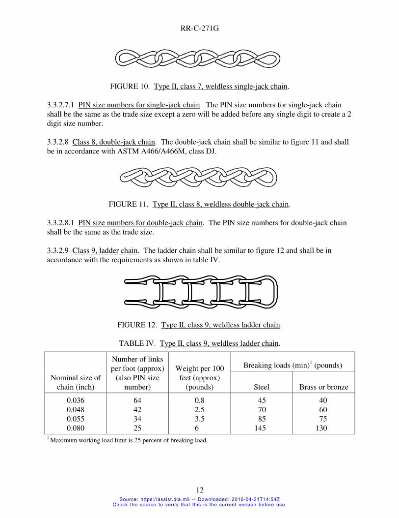
3.3.2.7 Class 7, single-jack chain. The single-jack chain shall be similar to figure 10 and shall
be in accordance with ASTM A466/A466M, class SJ.
Source: https://assist.dla.mil -- Downloaded: 2016-04-21T14:54ZCheck the source to verify that this is the current version before use.
RR-C-271G
12
FIGURE 10. Type II, class 7, weldless single-jack chain.
3.3.2.7.1 PIN size numbers for single-jack chain. The PIN size numbers for single-jack chain
shall be the same as the trade size except a zero will be added before any single digit to create a 2
digit size number.
3.3.2.8 Class 8, double-jack chain. The double-jack chain shall be similar to figure 11 and shall
be in accordance with ASTM A466/A466M, class DJ.
FIGURE 11. Type II, class 8, weldless double-jack chain.
3.3.2.8.1 PIN size numbers for double-jack chain. The PIN size numbers for double-jack chain
shall be the same as the trade size.
3.3.2.9 Class 9, ladder chain. The ladder chain shall be similar to figure 12 and shall be in
accordance with the requirements as shown in table IV.
FIGURE 12. Type II, class 9, weldless ladder chain.
TABLE IV. Type II, class 9, weldless ladder chain.
Nominal size of
chain (inch)
Number of links
per foot (approx)
(also PIN size
number)
Weight per 100
feet (approx)
(pounds)
Breaking loads (min)1 (pounds)
Steel Brass or bronze
0.036
0.048
0.055
0.080
64
42
34
25
0.8
2.5
3.5
6
45
70
85
145
40
60
75
130 1 Maximum working load limit is 25 percent of breaking load.
Source: https://assist.dla.mil -- Downloaded: 2016-04-21T14:54ZCheck the source to verify that this is the current version before use.

RR-C-271G
13
3.3.2.10 Class 10, register chain. The register chain shall be similar to figure 13 and shall be in
accordance with ASTM A466/A466M, class RG.
FIGURE 13. Type II, class 10, weldless register chain.
3.3.2.10.1 PIN size numbers for register chain. The PIN size numbers for register chain shall be
the same as the trade size.
3.3.2.11 Class 11, mechanical communication chain. The mechanical communication chain
shall be similar to figure 14 and shall be in accordance with the requirements as shown in
table V.
FIGURE 14. Type II, class 11, weldless mechanical communication chain.
TABLE V. Type II, class 11, weldless mechanical communication chain.
Nominal
thickness
outside links
(inch)
Nominal
thickness
inside links
(inch)
Width
(max)
(inch)
Pitch
(center-to-
center) of pins
(approx)
Number of
links per
foot
(approx)
Breaking
load (min)1
(pounds)
PIN
size
number
1/16 1/8 0.25 0.375 32 800 01 1 Maximum working load limit is 25 percent of breaking load.
3.3.2.11.1 End links. Each end of the completed chain shall be fitted with a large brass link for
the attachment of transmission wires.
3.3.2.11.2 Length. The total length of the finished chain shall be approximately 30 inches.
3.4 Detail requirements - attachments. The figures herein are descriptive, not restrictive, and are
not intended to preclude the purchase of attachments otherwise in accordance with this
specification.
3.4.1 Type II, connecting links. Connecting links shall be forged from carbon steel as specified
in B.2.2.1, shall be similar to figure 15, and shall be in accordance with the dimensions and
physical requirements as shown in table VI. The 3/16, 1/4, and 5/16-inch sizes shall have rivets
only, no interlocking lugs.
Source: https://assist.dla.mil -- Downloaded: 2016-04-21T14:54ZCheck the source to verify that this is the current version before use.

RR-C-271G
14
FIGURE 15. Type II, connecting links.
Source: https://assist.dla.mil -- Downloaded: 2016-04-21T14:54ZCheck the source to verify that this is the current version before use.

RR-C-271G
15
TABLE VI. Type II, connecting links.
Trade size
(nom)
(inch)
PIN
size
number
Outside
dimensions of
links (L x W)
(approx.)
(inches)
Weight per
dozen
(approx.)
(pounds)
Working
load limit
(pounds)
Proof load
(min)
(pounds)
Breaking
load
(min)
(pounds)
3/16
1/4
5/16
3/8
7/16
1/2
9/16
5/8
3/4
7/8
1
1-1/8
1-1/4
1-3/8
1-1/2
1-5/8
1-7/8
03
04
05
06
07
08
09
10
12
14
16
18
20
22
24
26
30
1.25 x 0.75
1.50 x 1.00
1.69 x 1.19
2.06 x 1.38
2.38 x 1.50
2.62 x 1.75
3.00 x 1.94
3.31 x 2.19
3.88 x 2.50
4.50 x 2.94
5.00 x 3.25
5.62 x 3.50
6.12 x 4.00
6.75 x 4.75
7.25 x 5.12
8.00 x 5.50
9.00 x 6.25
0.375
0.75
1
2
3.125
4.5
6.625
9
14.5
20.25
29
40
53.5
75
103
131
216
750
1,250
1,900
2,650
3,625
4,500
5,800
6,900
9,750
12,000
15,500
19,500
24,000
28,750
34,000
42,000
64,000
1,500
2,500
3,800
5,300
7,250
9,000
11,600
13,800
19,500
24,000
31,000
39,000
48,000
57,500
68,000
84,000
128,000
3,000
5,000
7,600
10,600
14,500
18,000
23,200
27,600
39,000
48,000
62,000
78,000
96,000
115,000
136,000
168,000
256,000
3.4.2 Type III, lap links. Lap links shall be formed from carbon steel as specified in B.2.2.2.
Links shall be of the lap type, shall be similar to figure 16, and shall be in accordance with the
dimensions and weights as shown in table VII.
FIGURE 16. Type III, lap link.
Source: https://assist.dla.mil -- Downloaded: 2016-04-21T14:54ZCheck the source to verify that this is the current version before use.

RR-C-271G
16
TABLE VII. Type III, lap links.
Diameter of
metal (inches)
PIN size
number Length inside
(nom) (inches)
Working load
limit (pounds)
Weight per 100
links (approx)
(pounds)
Breaking load
(min)
(pounds)
0.188
0.219
0.250
0.250
0.250
0.281
0.312
0.312
0.375
0.375
0.500
01
02
03
04
05
06
07
08
09
10
11
1.00
1.25
1.25
1.50
2.00
1.25
1.50
2.00
1.62
2.00
2.50
225
250
325
325
325
375
675
625
1,050
1,000
1,525
5
5.75
7.2
9
10.25
9.3
14.5
17
22
25
54
900
1,000
1,300
1,300
1,300
1,500
2,700
2,500
4,200
4,000
6,100
3.4.3 Type IV, shackles.
3.4.3.1 General. Type IVA and type IVB, grade A shackles shall be forged from carbon steel as
specified in B.2.2.3. Pins and bolts for grade A shackles shall be made from carbon or alloy steel
as specified in B.2.2.3.1 at the option of the manufacturer. Type IVA and type IVB, grade B
shackles, together with their pins and bolts, shall be forged from alloy steel as specified in
B.2.2.4.
3.4.3.1.1 Threads. Screw-pin shackles shall be threaded after fabrication to final size and shape.
Threads shall conform to ASME B1.1 for Unified Coarse (UNC/UNRC) threads unless the
corresponding fine threads are specified (see 6.2). Threads on finished shackles shall be not
looser than class 1 fit. The male threads of zinc-coated shackles may be undercut, as necessary,
so that after coating they will properly mate (not less than class 1 fit) with the standard size
female threads, or the inside threads may be similarly oversized.
3.4.3.1.2 Proof loads. Shackles shall withstand the proof loads shown in table VIII (see
4.4.2.2.1) without developing surface rupture or defects that would interfere with serviceability
or prevent disassembly of the pin. After proof loading, screw-pin shackles shall be disassembled
by hand after the first turn.
Source: https://assist.dla.mil -- Downloaded: 2016-04-21T14:54ZCheck the source to verify that this is the current version before use.

RR-C-271G
17
TABLE VIII. Mechanical properties.
Size (D)(1)
(nominal)
(inches)
PIN
size
number
Working load limit
(pounds)
Proof load (min)
(pounds)
Breaking load (min)
(pounds)
Grade A Grade B Grade A Grade B Grade A Grade B
3/16
1/4
5/16
3/8
7/16
1/2
5/8
3/4
7/8
1
1-1/8
1-1/4
1-3/8
1-1/2(2)
1-1/2(3)
1-5/8(2)
1-5/8(3)
1-3/4(2)
1-3/4(3)
2(2)
2(3)
2-1/4(4)
2-1/2(4)
2-3/4(4)
3(4)
3-1/2(4)
4(4)
03
04
05
06
07
08
10
12
14
16
18
20
22
24
24
26
26
28
28
32
32
36
40
44
48
56
64
650
1,000
1,500
2,000
3,000
4,000
6,500
9,500
13,000
17,000
19,000
24,000
27,000
34,000
34,000
40,000
40,000
50,000
50,000
70,000
70,000
80,000
110,000
120,000
170,000
240,000
300,000
1,000
1,500
2,500
4,000
5,200
6,600
10,000
14,000
19,000
25,000
30,000
36,000
42,000
50,000
60,000
58,000
70,000
68,000
80,000
86,000
100,000
120,000
160,000
180,000
220,000
280,000
350,000
1,430
2,200
3,300
4,400
6,600
8,800
14,300
20,900
28,600
37,400
41,800
52,800
59,400
74,800
74,800
88,000
88,000
110,000
110,000
154,000
154,000
176,000
242,000
264,000
374,000
528,000
660,000
2,200
3,300
5,500
8,800
11,440
14,520
22,000
30,800
41,800
55,000
66,000
79,200
92,400
110,000
132,000
127,600
154,000
149,600
176,000
189,200
220,000
264,000
352,000
396,000
484,000
616,000
770,000
3,250
5,000
7,500
10,000
15,000
20,000
32,500
47,500
65,000
85,000
95,000
120,000
135,000
170,000
170,000
200,000
200,000
250,000
250,000
350,000
350,000
400,000
550,000
600,000
850,000
1,200,000
1,500,000
5,000
7,500
12,500
20,000
26,000
33,000
50,000
70,000
95,000
125,000
150,000
180,000
210,000
250,000
300,000
290,000
350,000
340,000
400,000
430,000
500,000
600,000
800,000
900,000
1,100,000
1,400,000
1,750,000
(1) – all classes unless noted
(2) – class 1, grade A and B and class 2, grade A and B
(3) - class 3, grade A and B
(4) – class 1, 2 and 3, grade A; class 3, grade B (no class 1 or 2 in grade B in sizes 2-1/4 and
above)
Source: https://assist.dla.mil -- Downloaded: 2016-04-21T14:54ZCheck the source to verify that this is the current version before use.

RR-C-271G
18
3.4.3.1.3 Breaking loads. Shackles shall meet the breaking load requirements shown in
table VIII (see 4.4.2.2.2).
3.4.3.1.4 Working load limit. The working load limits (WLL) of shackles covered by this
specification are shown in table VIII.
3.4.3.1.5 Ductility. Shackles shall be sufficiently ductile so that, when fractured, the fractured
member shall show a permanent distortion before breaking. If the pin fractures, it shall show a
permanent bend of not less than 20 degrees. If the body fractures, it shall show a permanent mid-
shackle set of not less than 15 percent of the original spread between bows.
3.4.3.1.6 Marking. Each shackle body shall be permanently and legibly marked in raised or
stamped letters on the side of the shackle bow with the identifying manufacturer's name or
trademark, shackle size, and the WLL. As a minimum, all shackle pins and bolts shall be marked
with the manufacturer's mark or symbol; in addition, all grade B shackle pins and bolts shall be
marked with the raised or stamped letters "HS" on the head. Shackle markings shall be raised or
stamped letters or figures of the maximum practical height permitted by the size of the shackle
component being marked, but not to exceed 0.75 inch in height by 0.125 inch in relief. Stamping
dies shall be of the round bottom, low-stress type. Marking location shall not interfere with the
serviceability of the shackle assembly.
3.4.3.1.7 Finish. Shackle components shall be as specified in 3.2.1.3.
3.4.3.2 Form and dimensions. The form of the respective shackle types and classes shall be
similar to that shown on figures 17 and 18 (see 6.2). Except for reference dimensions, the
dimensions of shackle bodies and component pins and bolts shall conform to the dimensional
requirements specified in tables IX, X, XI, XII, XIII, and XIV. Reference dimensions are for
information only.
Source: https://assist.dla.mil -- Downloaded: 2016-04-21T14:54ZCheck the source to verify that this is the current version before use.

RR-C-271G
19
FIGURE 17. Type IVA, anchor shackles.
FIGURE 18. Type IVB, chain shackles.
Source: https://assist.dla.mil -- Downloaded: 2016-04-21T14:54ZCheck the source to verify that this is the current version before use.

TABLE IX. Type IVA, class 1, round pin and cotter anchor shackles.
Trade
size
(nom)
(inches)
Dimension
(D) (min)
(inches)
Diameter
pin (P)
(min)
(inches)
Diameter
inside eye
(E) (ref)
(inches)
Width between
eyes (W) ±
nominal tolerance
(inches)
Length inside (L)
± nominal
tolerance (inches)
Width
bow (B)
(min)
(inches)
Diameter
outside eye
(R) (max)
(inches)
Weight per
100 shackles
(approx)
(pounds)
3/16
1/4
5/16
3/8
7/16
1/2
5/8
3/4
7/8
1
1-1/8
1-1/4
1-3/8
1-1/2
1-5/8
1-3/4
2
2-1/4
2-1/2
3
3-1/2
4
0.18
0.24
0.30
0.36
0.42
0.48
0.59
0.71
0.83
0.95
1.07
1.19
1.31
1.42
1.54
1.66
1.90
2.14
2.38
2.85
3.32
3.80
0.24
0.30
0.37
0.43
0.49
0.61
0.73
0.85
0.98
1.10
1.22
1.34
1.46
1.58
1.71
1.95
2.19
2.44
2.68
3.17
3.66
4.14
0.29
0.40
0.47
0.53
0.59
0.72
0.84
0.97
1.09
1.22
1.34
1.47
1.62
1.75
1.87
2.15
2.40
2.65
2.90
3.40
3.90
4.40
0.38 ±0.13
0.47 ±0.13
0.53 ±0.13
0.66 ±0.13
0.75 ±0.13
0.81 ±0.13
1.06 ±0.13
1.25 ±0.13
1.44 ±0.13
1.69 ±0.13
1.81 ±0.13
2.03 ±0.13
2.25 ±0.19
2.38 ±0.19
2.62 ±0.19
2.88 ±0.19
3.25 ±0.19
3.88 ±0.19
4.12 ±0.25
5.00 ±0.25
5.25 ±0.25
5.50 ±0.25
0.88 ±0.06
1.13 ±0.06
1.25 ±0.06
1.44 ±0.13
1.69 ±0.13
1.88 ±0.13
2.38 ±0.13
2.81 ±0.25
3.31 ±0.25
3.75 ±0.25
4.25 ±0.25
4.69 ±0.25
5.25 ±0.25
5.75 ±0.25
6.25 ±0.25
7.00 ±0.25
7.75 ±0.50
9.25 ±0.50
10.50 ±0.50
13.00 ±0.75
15.00 ±0.75
14.50 ±0.75
0.56
0.75
0.81
0.93
1.06
1.18
1.50
1.75
2.00
2.31
2.62
2.87
3.25
3.37
4.00
4.50
5.25
5.50
6.75
7.37
9.00
10.50
0.63
0.88
1.00
1.13
1.25
1.38
1.88
2.13
2.38
2.63
2.88
3.25
3.50
3.75
4.13
4.50
5.25
5.75
6.25
6.75
8.50
9.50
5
12
18
30
49
74
144
216
337
530
700
960
1,260
1,730
2,200
2,780
4,110
5,600
8,350
11,900
21,200
30,500
RR
-C-2
71G
20
Source: https://assist.dla.mil -- Downloaded: 2016-04-21T14:54ZCheck the source to verify that this is the current version before use.

TABLE X. Type IVA, class 2, screw pin anchor shackles.
Trade
size
(nom)
(inches)
Dimension
(D) (min)
(inch)
Diameter
pin (P)
(min)
(inches)
Diameter
unthreaded
eye (E) (ref)
(inches)
Width between
eyes (W) ±
nom tolerance
(inches)
Length inside
(L) ± nom
tolerance
(inches)
Width
bow (B)
(min)
(inches)
Major
dia.
threaded
eye (ref)
(inches)
Dia. outside
eye (R)
(max)
(inches)
Weight per
100 shackles
(approx)
(pounds)
3/16
1/4
5/16
3/8
7/16
1/2
5/8
3/4
7/8
1
1-1/8
1-1/4
1-3/8
1-1/2
1-5/8
1-3/4
2
2-1/4
2-1/2
3
3-1/2
4
0.18
0.24
0.30
0.36
0.42
0.48
0.59
0.71
0.83
0.95
1.07
1.19
1.31
1.42
1.54
1.66
1.90
2.14
2.38
2.85
3.32
3.80
0.24
0.30
0.37
0.43
0.49
0.61
0.73
0.85
0.98
1.10
1.22
1.34
1.46
1.58
1.71
1.95
2.19
2.44
2.68
3.17
3.66
4.14
0.31
0.40
0.47
0.53
0.59
0.72
0.84
0.97
1.09
1.22
1.34
1.47
1.62
1.75
1.87
2.15
2.40
2.65
2.90
3.40
3.90
4.40
0.38 ±0.13
0.47 ±0.13
0.53 ±0.13
0.66 ±0.13
0.75 ±0.13
0.81 ±0.13
1.06 ±0.13
1.25 ±0.13
1.44 ±0.13
1.69 ±0.13
1.81 ±0.13
2.03 ±0.13
2.25 ±0.19
2.38 ±0.19
2.62 ±0.19
2.88 ±0.19
3.25 ±0.19
3.88 ±0.19
4.12 ±0.25
5.00 ±0.25
5.25 ±0.25
5.50 ±0.25
0.88 ±0.06
1.13 ±0.06
1.25 ±0.06
1.44 ±0.13
1.69 ±0.13
1.88 ±0.13
2.38 ±0.13
2.81 ±0.25
3.31 ±0.25
3.75 ±0.25
4.25 ±0.25
4.69 ±0.25
5.25 ±0.25
5.75 ±0.25
6.25 ±0.25
7.00 ±0.25
7.75 ±0.50
9.25 ±0.50
10.50 ±0.50
13.00 ±0.75
15.00 ±0.75
14.50 ±0.75
0.56
0.75
0.81
0.93
1.06
1.18
1.50
1.75
2.00
2.31
2.62
2.87
3.25
3.37
4.00
4.50
5.25
5.50
6.75
7.37
9.00
10.50
0.281
0.344
0.406
0.469
0.531
0.656
0.781
0.906
1.031
1.156
1.297
1.422
1.547
1.672
1.797
2.047
2.297
2.547
2.797
3.297
3.797
4.297
0.63
0.88
1.00
1.12
1.25
1.37
1.87
2.12
2.37
2.62
2.87
3.25
3.50
3.75
4.12
4.50
5.25
5.75
6.25
6.75
8.50
9.50
5
12
18
30
49
74
144
216
337
530
700
960
1,260
1,730
2,200
2,780
4,110
5,600
8,350
11,900
21,200
30,500
RR
-C-2
71G
21
Source: https://assist.dla.mil -- Downloaded: 2016-04-21T14:54ZCheck the source to verify that this is the current version before use.

TABLE XI. Type IVA, class 3, bolt, nut and cotter anchor shackles.
Trade
size
(nom)
(inches)
Dimension
(D) (min)
(inch)
Diameter
bolt (P)
(min)
(inches)
Diameter
inside
eye (E)
(ref)
(inches)
Width between
eyes (W) ± nom
tolerance
(inches)
Length inside
(L) ± nom
tolerance
(inches)
Width
bow (B)
(min)
(inches)
Diameter
outside
eye (R)
(max)
(inches)
Weight per
100 shackles
(approx)
(pounds)
3/16
1/4
5/16
3/8
7/16
1/2
5/8
3/4
7/8
1
1-1/8
1-1/4
1-3/8
1-1/2
1-5/8
1-3/4
2
2-1/4
2-1/2
3
3-1/2
4
0.18
0.24
0.30
0.36
0.42
0.48
0.59
0.71
0.83
0.95
1.07
1.19
1.31
1.42
1.54
1.66
1.90
2.14
2.38
2.85
3.32
3.80
0.24
0.30
0.36
0.43
0.49
0.61
0.73
0.85
0.98
1.10
1.22
1.34
1.46
1.58
1.71
1.95
2.19
2.44
2.68
3.17
3.66
4.14
0.29
0.40
0.47
0.53
0.59
0.72
0.84
0.97
1.09
1.22
1.34
1.47
1.62
1.75
1.87
2.15
2.40
2.65
2.90
3.40
3.90
4.40
0.38 ±0.13
0.47 ±0.13
0.53 ±0.13
0.66 ±0.13
0.75 ±0.13
0.81 ±0.13
1.06 ±0.13
1.25 ±0.13
1.44 ±0.13
1.69 ±0.13
1.81 ±0.13
2.03 ±0.13
2.25 ±0.19
2.38 ±0.19
2.62 ±0.19
2.88 ±0.19
3.25 ±0.19
3.88 ±0.19
4.12 ±0.25
5.00 ±0.25
5.25 ±0.25
5.50 ±0.25
0.88 ±0.06
1.13 ±0.06
1.25 ±0.06
1.44 ±0.13
1.69 ±0.13
1.88 ±0.13
2.38 ±0.13
2.82 ±0.25
3.31 ±0.25
3.75 ±0.25
4.25 ±0.25
4.69 ±0.25
5.25 ±0.25
5.75 ±0.25
6.25 ±0.25
7.00 ±0.25
7.75 ±0.50
9.25 ±0.50
10.50 ±0.50
13.00 ±0.75
15.00 ±0.75
14.50 ±0.75
0.56
0.75
0.81
0.93
1.06
1.18
1.50
1.75
2.00
2.31
2.62
2.87
3.25
3.37
4.00
4.50
5.25
5.50
6.75
7.37
9.00
10.50
0.63
0.88
1.00
1.13
1.25
1.38
1.88
2.13
2.38
2.63
2.88
3.25
3.50
3.75
4.13
4.50
5.25
5.75
6.25
6.75
8.50
9.50
5
12
18
30
49
82
158
280
395
560
785
1,120
1,520
1,950
2,410
3,130
4,630
5,650
9,400
14,500
26,500
35,800
RR
-C-2
71G
22
Source: https://assist.dla.mil -- Downloaded: 2016-04-21T14:54ZCheck the source to verify that this is the current version before use.

TABLE XII. Type IVB, class 1, round pin and cotter chain shackles.
Trade size
(nom)
(inches)
Dimension
(D) (min)
(inch)
Diameter
pin (P)
(min)
(inches)
Diameter
inside eye
(E) (ref)
(inches)
Width between
eyes (W) ± nom
tolerance
(inches)
Length inside (L)
± nom tolerance
(inches)
Diameter
outside
eye (R)
(max)
(inches)
Weight per
100 shackles
(approx)
(pounds)
3/16
1/4
5/16
3/8
7/16
1/2
5/8
3/4
7/8
1
1-1/8
1-1/4
1-3/8
1-1/2
1-5/8
1-3/4
2
2-1/4
2-1/2
3
3-1/2
4
0.18
0.24
0.30
0.36
0.42
0.48
0.59
0.71
0.83
0.95
1.07
1.19
1.31
1.42
1.54
1.66
1.90
2.14
2.38
2.85
3.32
3.80
0.24
0.30
0.37
0.43
0.49
0.61
0.73
0.85
0.98
1.10
1.22
1.34
1.46
1.58
1.71
1.95
2.19
2.44
2.68
3.17
3.66
4.14
0.31
0.40
0.47
0.53
0.59
0.72
0.84
0.97
1.09
1.22
1.34
1.47
1.62
1.75
1.88
2.15
2.40
2.65
2.90
3.40
3.90
4.40
0.38 ±0.13
0.47 ±0.13
0.53 ±0.13
0.66 ±0.13
0.75 ±0.13
0.81 ±0.13
1.06 ±0.13
1.25 ±0.13
1.44 ±0.13
1.69 ±0.13
1.81 ±0.13
2.03 ±0.13
2.25 ±0.19
2.38 ±0.19
2.62 ±0.19
2.88 ±0.19
3.25 ±0.19
3.88 ±0.19
4.13 ±0.25
5.00 ±0.25
5.25 ±0.25
5.50 ±0.25
0.75 ±0.06
0.88 ±0.06
1.03 ±0.06
1.25 ±0.13
1.44 ±0.13
1.62 ±0.13
2.00 ±0.13
2.38 ±0.25
2.81 ±0.25
3.19 ±0.25
3.56 ±0.25
3.94 ±0.25
4.44 ±0.25
4.88 ±0.25
5.25 ±0.25
5.75 ±0.25
6.75 ±0.50
7.13 ±0.50
8.00 ±0.50
9.00 ±0.75
10.50 ±0.75
12.00 ±0.75
0.63
0.88
1.00
1.13
1.25
1.38
1.88
2.13
2.38
2.63
2.88
3.25
3.50
3.75
4.13
4.50
5.25
5.75
6.25
6.75
8.50
9.50
5
11
17
28
42
68
121
214
310
450
660
890
1,200
1,620
2,020
2,500
3,600
5,000
7,400
10,600
18,900
27,100
RR
-C-2
71G
23
Source: https://assist.dla.mil -- Downloaded: 2016-04-21T14:54ZCheck the source to verify that this is the current version before use.

TABLE XIII. Type IVB, class 2, screw pin chain shackles.
Trade
size
(nom)
(inches)
Dimension
(D) (min)
(inch)
Diameter
pin (P)
(min)
(inches)
Diameter
unthreaded
eye (E) (ref)
(inches)
Width between
eyes (W) ± nom
tolerance
(inches)
Length inside (L)
± nom tolerance
(inches)
Major
dia.
threaded
eye (ref)
(inches)
Dia.
outside eye
(R) (max)
(inches)
Weight per
100 shackles
(approx)
(pounds)
3/16
1/4
5/16
3/8
7/16
1/2
5/8
3/4
7/8
1
1-1/8
1-1/4
1-3/8
1-1/2
1-5/8
1-3/4
2
2-1/4
2-1/2
3
3-1/2
4
0.18
0.24
0.30
0.36
0.42
0.48
0.59
0.71
0.83
0.95
1.07
1.19
1.31
1.42
1.54
1.66
1.90
2.14
2.38
2.85
3.32
3.80
0.24
0.30
0.37
0.43
0.49
0.61
0.73
0.85
0.98
1.10
1.22
1.34
1.46
1.58
1.71
1.95
2.19
2.44
2.68
3.17
3.66
4.14
0.31
0.40
0.47
0.53
0.59
0.72
0.84
0.97
1.09
1.22
1.34
1.47
1.62
1.75
1.88
2.15
2.40
2.65
2.90
3.40
3.90
4.40
0.38 ±0.13
0.47 ±0.13
0.53 ±0.13
0.66 ±0.13
0.75 ±0.13
0.81 ±0.13
1.06 ±0.13
1.25 ±0.13
1.44 ±0.13
1.69 ±0.13
1.81 ±0.13
2.03 ±0.13
2.25 ±0.19
2.38 ±0.19
2.63 ±0.19
2.88 ±0.19
3.25 ±0.19
3.88 ±0.19
4.13 ±0.25
5.00 ±0.25
5.25 ±0.25
5.50 ±0.25
0.75 ±0.06
0.88 ±0.06
1.03 ±0.06
1.13 ±0.13
1.44 ±0.13
1.63 ±0.13
2.00 ±0.13
2.38 ±0.25
2.81 ±0.25
3.19 ±0.25
3.56 ±0.25
3.94 ±0.25
4.44 ±0.25
4.88 ±0.25
5.25 ±0.25
5.75 ±0.25
6.75 ±0.50
7.13 ±0.50
8.00 ±0.50
9.00 ±0.75
10.50 ±0.75
12.00 ±0.75
0.281
0.344
0.406
0.469
0.531
0.656
0.781
0.906
1.031
1.156
1.297
1.422
1.547
1.672
1.797
2.047
2.297
2.547
2.797
3.297
3.797
4.297
0.63
0.88
1.00
1.25
1.25
1.38
1.88
2.13
2.38
2.63
2.88
3.25
3.50
3.75
4.13
4.50
5.25
5.75
6.25
6.75
8.50
9.50
5
11
17
28
42
68
121
214
310
450
660
890
1,200
1,620
2,020
2,500
3,600
5,000
7,400
10,600
18,900
27,100
RR
-C-2
71G
24
Source: https://assist.dla.mil -- Downloaded: 2016-04-21T14:54ZCheck the source to verify that this is the current version before use.

TABLE XIV. Type IVB, class 3, bolt, nut and cotter chain shackles.
Trade
size
(nom)
(inches)
Dimension
(D) (min)
(inch)
Diameter
bolt (P)
(min)
(inches)
Diameter
inside eye
(E) (ref)
(inches)
Width between
eyes (W)
(inches)
Length inside (L)
(inches)
Diameter
outside eye
(R) (max)
(inches)
Weight per
100 shackles
(approx)
(pounds)
3/16
1/4
5/16
3/8
7/16
1/2
5/8
3/4
7/8
1
1-1/8
1-1/4
1-3/8
1-1/2
1-5/8
1-3/4
2
2-1/2
3
3-1/2
4
0.18
0.24
0.30
0.36
0.42
0.48
0.59
0.71
0.83
0.95
1.07
1.19
1.31
1.42
1.54
1.66
1.90
2.38
2.85
3.32
3.80
0.24
0.30
0.36
0.43
0.49
0.61
0.73
0.85
0.98
1.10
1.22
1.34
1.46
1.58
1.71
1.95
2.19
2.68
3.17
3.66
4.14
0.31
0.40
0.47
0.53
0.59
0.72
0.84
0.97
1.09
1.22
1.34
1.47
1.63
1.75
1.88
2.15
2.40
2.90
3.40
3.90
4.40
0.38 ±0.13
0.47 ±0.13
0.53 ±0.13
0.66 ±0.13
0.75 ±0.13
0.81 ±0.13
1.06 ±0.13
1.25 ±0.13
1.44 ±0.13
1.69 ±0.13
1.81 ±0.13
2.03 ±0.13
2.25 ±0.19
2.38 ±0.19
2.63 ±0.19
2.88 ±0.19
3.25 ±0.19
4.13 ±0.25
5.00 ±0.25
5.25 ±0.25
5.50 ±0.25
0.75 ±0.06
0.88 ±0.06
1.03 ±0.06
1.25 ±0.13
1.44 ±0.13
1.63 ±0.13
2.00 ±0.13
2.38 ±0.25
2.81 ±0.25
3.19 ±0.25
3.56 ±0.25
3.94 ±0.25
4.44 ±0.25
4.88 ±0.25
5.25 ±0.25
5.75 ±0.25
6.75 ±0.50
8.00 ±0.50
9.00 ±0.75
10.50 ±0.75
12.00 ±0.75
0.63
0.88
1.00
1.13
1.25
1.38
1.88
2.13
2.38
2.63
2.88
3.25
3.50
3.75
4.13
4.50
5.25
6.25
6.75
8.50
9.50
5
11
17
28
42
76
156
262
365
535
727
1,020
1,335
1,850
2,310
2,850
4,110
8,450
12,300
21,800
31,000
RR
-C-2
71G
25
Source: https://assist.dla.mil -- Downloaded: 2016-04-21T14:54ZCheck the source to verify that this is the current version before use.

RR-C-271G
26
3.4.4 Type V, Hooks. The hook bodies shall be forged. Class 1, 5 and 6 hooks shall be forged
from alloy steel as specified in B.2.2.5.1. Class 2 and 4 hooks shall be forged from carbon steel
as specified in B.2.2.5.2. Class 3 hooks shall be forged from carbon steel or alloy steel as
specified in B.2.2.5.3. Refer to section 1.2, Type V – Hooks, for listed class, grade and style
combinations.
3.4.4.1 Ductility. Hooks shall be sufficiently ductile so that, when fractured, the fractured
member shall show a permanent distortion before breaking. The throat opening shall show a
permanent bend of not less than 15 degrees.
3.4.4.2 Finish. Hooks shall be finished as specified in 3.2.1.3.
3.4.4.3 Hook styles. Hooks shall be of one of the following styles.
3.4.4.3.1 Class 1 through 4, style 1 slip hook and style 3 sling hooks. For use to connect a chain
to a load. Style 1 is for use when connecting to a chain sling and style 3 is for use when
connecting to a fabric sling. Basic hook configuration shall be similar to figure 19 (a) or (b) as
specified.
(a) Eye attachment (style 1E and 3E) (b) Clevis attachment (style 3C and 3C)
Figure 19. Basic hook design – slip and sling hooks
Actual design at manufacturer’s option
Source: https://assist.dla.mil -- Downloaded: 2016-04-21T14:54ZCheck the source to verify that this is the current version before use.

RR-C-271G
27
3.4.4.3.2 Class 1 through 4, style 2 grab hook. For use to attach to a chain at a specific link.
Basic hook configuration shall be similar to figure 20
(a) Eye attachment (style 2E) (b) Clevis attachment (style 2C)
Figure 20. Basic hook design – grab hook
Actual design at manufacturer’s option
3.4.4.3.3 Class 5 hoist hooks. Typically for use with wire rope, not chain and to connect to the
load. Basic hook configuration shall be similar to figure 21
(a) Eye attachment (style 4E) (b) Clevis attachment (style 4C)
Figure 21. Basic hook design – hoist hooks
Actual design at manufacturer’s option
Source: https://assist.dla.mil -- Downloaded: 2016-04-21T14:54ZCheck the source to verify that this is the current version before use.

RR-C-271G
28
3.4.4.3.4 Class 6 barrel hooks. Eye barrel hooks shall be similar to figure 22 and shall have a
nominal overall length of 5 inches.
FIGURE 22. Type V, class 6, eye barrel hook.
3.4.4.4 Attachment. Hook attachment shall be an integral eye or clevis or a swivel eye as shown
in figures 19, 20 and 21 except class 6 which shall have an eye as shown in figure 22
3.4.4.5 Mechanical requirements. Hooks shall meet the following minimum mechanical
requirements.
3.4.4.5.1 Class 1, grade A and B hooks. All styles of class 1 hooks shall meet the mechanical
requirements of ASTM A952/A952M. Grade A hooks shall conform to grade 80 requirements
and grade B shall conform to grade 100 requirements.
3.4.4.5.2 Class 2 hooks. All styles of class 2 hooks shall meet the mechanical requirements of
ASTM A413/A413M, grade 43 chain.
3.4.4.5.3 Class 3 hooks. All styles of class 2 hooks shall meet the mechanical requirements of
ASTM A413/A413M, grade 70 chain.
3.4.4.5.4 Class 4 hooks. All styles of class 2 hooks shall meet the mechanical requirements of
ASTM A413/A413M, grade 30 chain.
3.4.4.5.5 Class 5 hooks. All styles of class 5 hooks shall meet or exceed the mechanical
requirements of table XV.
Source: https://assist.dla.mil -- Downloaded: 2016-04-21T14:54ZCheck the source to verify that this is the current version before use.

RR-C-271G
29
TABLE XV. Mechanical requirements for type V, class 5 hoist hooks.
Hook
Size
PIN
Size
Number
Working
Load Limit
(pounds)
Proof Load
(min)
(pounds)
Breaking
Load (min)
(pounds)
1 ton 010 2,000 4,000 8,000
1.5 ton 015 3,000 6,000 12,000
2 ton 020 4,000 8,000 16,000
3 ton 030 6,000 12,000 24,000
4.5 ton 045 9,000 18,000 36,000
7 ton 070 14,000 28,000 56,000
11 ton 110 22,000 44,000 88,000
15 ton 150 30,000 60,000 120,000
22 ton 220 44,000 88,000 176,000
30 ton 300 60,000 120,000 240,000
37 ton 370 74,000 148,000 296,000
3.4.4.5.6 Class 6 hooks. Class 6 hooks shall withstand a proof load of 5,500 pounds.
3.4.5 Type VI, rings. The rings shall be forged or welded from alloy steel as specified in
B.2.2.6. The rings shall be heat treated, be similar to figure 23, and shall be accordance with the
sizes and weights as shown in table XVI.
FIGURE 23. Type VI, ring.
Source: https://assist.dla.mil -- Downloaded: 2016-04-21T14:54ZCheck the source to verify that this is the current version before use.

RR-C-271G
30
TABLE XVI. Type VI, rings.
Diameter
stock (D)
(nom)
(inches)
Inside
diameter
(ID) (nom)
(inches)
PIN
size
number
Weight
each
(approx)
(pounds)
Working
load limit
(pounds)
Proof load
(min)
(pounds)
Breaking
load (min)
(pounds)
0.75
0.875
0.875
1
1.125
1.25
1.375
1.5
4
4
5.5
4
6
7
6
6
41
42
52
43
64
75
66
67
1.8
2.6
3.4
3.5
6.5
6.8
10.38
11.7
6,400
7,200
5,600
10,800
10,400
17,000
19,000
34,900
12,800
14,400
11,200
21,600
20,800
34,000
38,000
69,800
38,400
43,200
33,600
64,800
62,400
102,000
114,000
209,400
3.4.5.1 Finish. Rings shall be as specified in 3.2.1.3.
3.4.6 Type VII, swivels.
3.4.6.1 General. Type VII swivels, together with their pins, shall be forged from carbon steel as
specified in B.2.2.7. Nuts shall be regular hexagonal.
3.4.6.1.1 Finish. The swivels and pins shall be as specified in 3.2.1.3.
3.4.6.1.2 Proof load. The swivels shall withstand the proof loads in the respective class tables
(see table XVII, table XVIII or table XIX and 4.4.2.5.1).
3.4.6.1.3 Breaking load. The swivels shall withstand, without breaking, breaking loads shown in
the respective class tables (see table XVII, table XVIII or table XIX and 4.4.2.5.1).
Source: https://assist.dla.mil -- Downloaded: 2016-04-21T14:54ZCheck the source to verify that this is the current version before use.

RR-C-271G
31
3.4.6.2 Type VII, class 1, chain swivels. The chain swivels shall be similar to figure 24 and
shall be in accordance with the dimensions and physical requirements as shown in table XVII.
FIGURE 24. Type VII, class 1, chain swivel.
TABLE XVII. Type VII, class 1, chain swivels.
Trade
size
(nom)
(inch)
PIN
Size
Number
Length
(L)
(min)
(inch)
Width
(W)
(nom)
(inches)
Eye dia.
(D)
(min)
Weight
per 100
(approx)
(pounds)
Working
load limit
(pounds)
Proof
load
(min)
(pounds)
Breaking
load (min)
(pounds)
1/4
5/16
3/8
1/2
5/8
3/4
08
10
12
16
20
24
2.250
2.719
3.438
4.250
5.125
5.781
0.75
1.00
1.25
1.50
1.75
2.00
0.43
0.50
0.75
0.87
1.06
1.25
13
25
50
100
175
287
800
1,200
2,200
3,500
5,200
7,100
1,600
2,400
4,400
7,000
10,400
14,200
4,000
6,000
11,000
17,500
26,000
35,500
Source: https://assist.dla.mil -- Downloaded: 2016-04-21T14:54ZCheck the source to verify that this is the current version before use.

RR-C-271G
32
3.4.6.3 Class 2, eye and eye swivels. The eye and eye swivels shall be similar to figure 25, and
shall be in accordance with the dimensions and physical requirements as shown in table XVIII.
FIGURE 25. Type VII, class 2, eye and eye swivel.
TABLE XVIII. Type VII, class 2, eye and eye swivels.
Trade
size
(nom)
(inch)
PIN
Size
Number
Length
(L)
(min)
(inch)
Width
(W)
(nom)
(inches)
Weight
per 100
(approx)
(pounds)
Working
load limit
(pounds)
Proof load
(min)
(pounds)
Breaking
load (min)
(pounds)
1/4
5/16
3/8
1/2
5/8
3/4
7/8
1
1-1/8
1-1/4
1-1/2
08
10
12
16
20
24
28
32
36
40
48
2.875
3.500
4.250
5.438
6.562
7.188
8.375
9.625
10.375
11.125
16.688
0.75
1.00
1.25
1.50
1.75
2.00
2.25
2.50
2.75
3.12
4.00
17.5
32.5
63
132
250
375
600
900
1,246
1,637
4,906
800
1,200
2,200
3,500
5,200
7,100
9,200
11,600
15,000
18,000
45,000
1,600
2,400
4,400
7,000
10,400
14,200
18,400
23,200
30,000
36,000
90,000
4,000
6,000
11,000
17,500
26,000
35,500
46,000
56,200
75,000
90,000
225,000
Source: https://assist.dla.mil -- Downloaded: 2016-04-21T14:54ZCheck the source to verify that this is the current version before use.

RR-C-271G
33
3.4.6.4 Class 3, jaw and eye swivels. The jaw and eye swivels shall be similar to figure 26, and
shall be in accordance with the dimensions and physical requirements as shown in table XIX.
FIGURE 26. Type VII, class 3, jaw and eye swivel.
TABLE XIX. Type VII, class 3, jaw and eye swivels.
Trade
size
(nom)
(inch)
PIN
Size
Number
Length
(L)
(min)
(inch)
Width
(W)
(nom)
(inch)
Jaw
opening
(J)
(min)
(inch)
Pin dia.
(P)
(min)
(inch)
Weight
per 100
(approx)
(pounds)
Working
load
limit
(pounds)
Proof
load
(min)
(pounds)
Breaking
load
(min)
(pounds)
1/4
5/16
3/8
1/2
5/8
3/4
7/8
1
1-1/8
1-1/4
1-1/2
08
10
12
16
20
24
28
32
36
40
48
2.438
2.812
3.500
4.500
5.312
6.062
7.000
8.250
8.938
9.438
14.250
0.75
1.00
1.25
1.50
1.75
2.00
2.25
2.50
2.75
3.12
4.00
0.46
0.50
0.62
0.75
0.93
1.12
1.18
1.75
1.75
2.06
2.87
0.25
0.31
0.37
0.50
0.62
0.75
0.87
1.12
1.12
1.37
2.25
21
34
62
125
235
350
575
950
1,100
1,575
5,475
800
1,200
2,200
3,500
5,200
7,100
9,200
11,600
15,000
18,000
45,000
1,600
2,400
4,400
7,000
10,400
14,200
18,400
23,200
30,000
36,000
90,000
4,000
6,000
11,000
17,500
26,000
35,500
46,000
56,200
75,000
90,000
225,000
Source: https://assist.dla.mil -- Downloaded: 2016-04-21T14:54ZCheck the source to verify that this is the current version before use.

RR-C-271G
34
3.4.7 Type IX, bead-chain fasteners (standard couplings with eyelets). The bead-chain fasteners
shall be made of brass, corrosion resistant steel (CRES), or steel as specified in B.2.2.8, shall be
similar to figure 27, and shall be in accordance with the dimensions and physical requirements as
shown in table XX.
FIGURE 27. Type IX, bead-chain fastener.
TABLE XX. Type IX, bead-chain fasteners.
Trade no.
PIN
Size
Number
Size of chain
used with
(inch)
Length overall
(approx)
(inches)
Diameter of
hole in eye
(approx) (inch)
Weight per 100
couplings
(approx)
(pounds)
6 - AD
10 - A
10 - AD
13 - AN
20 - A
06
10
11
13
20
1/8
3/16
3/16
1/4
3/8
0.406
0.500
0.562
0.688
1.031
0.125
0.125
0.188
0.188
0.250
0.100
0.187
0.250
0.312
1.320
Source: https://assist.dla.mil -- Downloaded: 2016-04-21T14:54ZCheck the source to verify that this is the current version before use.

RR-C-271G
35
3.4.8 Type X, bead chain couplings. The bead-chain couplings shall be made of brass, CRES, or
steel as specified in B.2.2.9, shall be similar to figure 28, and shall be in accordance with the
dimensions and physical requirements as shown in table XXI.
FIGURE 29. Type X, bead-chain coupling.
TABLE XXI. Type X, bead-chain couplings.
Trade no.
PIN
Size
Number
Size of chain
used with
(inch)
Length overall
(approx)
(inches)
Ring wire size
(max)
(inch)
Weight per 100
couplings
(approx)
(pounds)
3-L
6-L
10-B
13-B
03
06
10
13
3/32
1/8
3/16
1/4
0.375
0.500
0.531
0.688
-
-
0.125
0.141
0.0386
0.085
0.150
0.420
Source: https://assist.dla.mil -- Downloaded: 2016-04-21T14:54ZCheck the source to verify that this is the current version before use.

RR-C-271G
36
3.4.9 Type XI, bead-chain insulating couplings. The bead-chain insulating couplings shall be as
shown on figure 30, and shall be in accordance with the dimensions and physical requirements
shown in table XXII. The couplings shall have a hard fiber body fitted at each end with a brass,
CRES or steel as specified in B.2.2.10 cap that shall have a hole and slot to receive bead chain.
The couplings shall withstand dielectric strength tests (see 4.4.2.6).
FIGURE 30. Type XI, bead-chain insulating coupling.
TABLE XXII. Type XI, bead-chain insulating coupling.
Size of chain
used with
(inch)
Length overall
(approx)
(inches)
Distance
between
metal ends
(min)
(inch)
Diameter of
fiber rod
(approx)
(inch)
Breaking load
(min)
(pounds)
1/8 1.094 0.5 0.219 25
3.4.10 Type XIII, pear-shaped links. The pear-shaped links shall be forged or welded from alloy
steel as specified in B.2.2.11. The links shall be heat treated, be similar to figure 31, and shall be
in accordance with the sizes and weights as shown in table XXIII.
Source: https://assist.dla.mil -- Downloaded: 2016-04-21T14:54ZCheck the source to verify that this is the current version before use.

RR-C-271G
37
FIGURE 31. Type XIII, pear-shaped link.
TABLE XXIII. Type XIII, pear-shaped links.
Nominal
diameter
(A)
(inches)
PIN
Size
Number
Inside widths Inside
length
(D)
(approx)
(inches)
Working
load limit
(pounds)
Proof
load
(min)
(pounds)
Breaking
load
(min)
(pounds)
Weight
each
(approx)
(pounds)
(B)
(min)
(inches)
(C)
(min)
(inches)
1/2
5/8
3/4
7/8
1
1-1/4
1-3/8
1-1/2
16
20
24
28
32
40
42
48
1.00
1.25
1.50
1.75
2.00
2.50
2.75
3.00
2.00
2.50
2.75
3.00
3.50
4.37
5.00
5.25
3.00
3.75
4.50
5.25
6.00
7.75
8.25
10.50
3,600
6,250
9,000
11,400
16,000
25,650
30,750
34,900
7,200
12,500
18,000
22,800
32,000
51,300
61,500
69,800
14,400
25,000
36,000
45,600
64,000
102,600
123,000
139,600
0.8
1.4
2.1
2.8
4.6
9.0
11.5
15.3
3.4.10.1 Finish. The pear-shaped links shall be shall be zinc coated in accordance with 3.2.1.4.
Source: https://assist.dla.mil -- Downloaded: 2016-04-21T14:54ZCheck the source to verify that this is the current version before use.
RR-C-271G
38
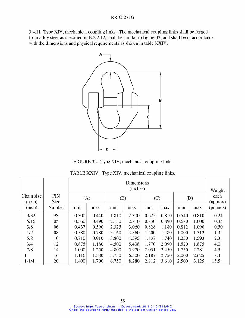
3.4.11 Type XIV, mechanical coupling links. The mechanical coupling links shall be forged
from alloy steel as specified in B.2.2.12, shall be similar to figure 32, and shall be in accordance
with the dimensions and physical requirements as shown in table XXIV.
FIGURE 32. Type XIV, mechanical coupling link.
TABLE XXIV. Type XIV, mechanical coupling links.
Chain size
(nom)
(inch)
PIN
Size
Number
Dimensions
(inches) Weight
each
(approx)
(pounds)
(A) (B) (C) (D)
min max min max min max min max
9/32
5/16
3/8
1/2
5/8
3/4
7/8
1
1-1/4
9S
05
06
08
10
12
14
16
20
0.300
0.360
0.437
0.580
0.710
0.875
1.000
1.116
1.400
0.440
0.490
0.590
0.780
0.910
1.180
1.250
1.380
1.700
1.810
2.130
2.325
3.160
3.800
4.500
4.800
5.750
6.750
2.300
2.810
3.060
3.860
4.595
5.438
5.970
6.500
8.280
0.625
0.830
0.828
1.200
1.437
1.770
2.031
2.187
2.812
0.810
0.890
1.180
1.480
1.740
2.090
2.450
2.750
3.610
0.540
0.680
0.812
1.000
1.250
1.520
1.750
2.000
2.500
0.810
1.000
1.090
1.312
1.593
1.875
2.281
2.625
3.125
0.24
0.35
0.50
1.3
2.3
4.0
4.3
8.4
15.5
Source: https://assist.dla.mil -- Downloaded: 2016-04-21T14:54ZCheck the source to verify that this is the current version before use.

RR-C-271G
39
TABLE XXIV. Type XIV, mechanical coupling links (continued).
Chain size
(nom)
(inch)
PIN
Size
Number
Working load limit
(pounds)
Proof load (min)
(pounds)
Breaking load (min)
(pounds)
Grade A Grade B Grade A Grade B Grade A Grade B
9/32
5/16
3/8
1/2
5/8
3/4
7/8
1
1-1/4
9S
05
06
08
10
12
14
16
20
3,500
4,500
7,100
12,000
18,100
28,300
34,200
47,700
72,300
4,300
5,700
8,800
15,000
22,600
35,300
42,700
7,000
9,000
14,200
24,000
36,200
56,600
68,400
95,400
144,600
8,600
11,400
17,600
30,000
45,200
70,600
85,400
14,000
18,000
28,400
48,000
72,400
113,200
136,800
190,400
289,200
17,200
22,800
35,200
60,000
90,400
141,200
170,800
3.4.12 Type XV, end links. The end links shall be manufactured from carbon or alloy steel
conforming, as specified in B.2.2.13, and the limitation in chemical composition shall be as
specified in table I; the links shall be heat treated, weldless, and similar to figure 33; and the links
shall be in accordance with the dimensions and physical requirements as shown in table XXV.
FIGURE 33. Type XV, end link.
Source: https://assist.dla.mil -- Downloaded: 2016-04-21T14:54ZCheck the source to verify that this is the current version before use.

RR-C-271G
40
TABLE XXV. Type XV, end links.
Trade size
(nom)
(inches)
PIN
Size
Number
Inside
length
(nom)
(inches)
Inside
width
(nom)
(inches)
Weight
each
(approx)
(pounds)
Working
load limit
(pounds)
Proof load
(min)
(pounds)
Breaking
load (min)
(pounds)
0.625
0.75
0.875
1
01
02
03
04
3.25
3.50
5.12
4.00
1.00
1.12
2.00
1.50
0.95
1.51
2.75
3.95
3,537
5,525
7,950
23,750
7,070
11,050
15,900
50,000
14,150
22,100
31,800
95,000
3.4.12.1 Finish. Links shall be zinc coated as specified in 3.2.1.4.
3.4.13 Type XVI, chain master links. The chain master links shall meet the requirements of
ASTM A952/A952M for the sizes and grades listed in table XXVI.
TABLE XXVI. Type XVI, chain master links.
Nominal size Grade 80 PIN (see note) Grade 100 PIN (see note)
5/16 105X 205X
3/8 106X 206X
1/2 108X 208X
5/8 110X 210X
3/4 112X 212X
7/8 114X 214X
1 116X 216X
1-1/4 120X 220X
Note: PIN is: first digit is grade, second and third are size in 16ths, forth is number of legs (1-4)
3.5 Workmanship. The chain and attachments shall be free from injurious imperfections and
defects that may impair appearance or serviceability. Chain and attachments shall be free from
fins, cracks, flaws, or seams. The screw threads shall be true to form, clean cut, and free from
injurious defects.
4. QUALITY ASSURANCE PROVISIONS
4.1 Responsibility for inspection. Unless otherwise specified in the contract, the contractor is
responsible for the performance of all inspection requirements as specified herein. Except as
otherwise specified in the contract, the contractor may use his own or any other facilities suitable
for the performance of the inspection requirements specified herein, unless disapproved by the
government. The government reserves the right to perform any of the inspections set forth in the
specification where such inspections are deemed necessary to assure that supplies and services
conform to prescribed requirements.
Source: https://assist.dla.mil -- Downloaded: 2016-04-21T14:54ZCheck the source to verify that this is the current version before use.

RR-C-271G
41
4.1.1 Responsibility for compliance. All items shall meet all requirements of sections 3 and 5.
The inspections set forth in this specification shall become a part of the contractor's overall
inspection system or quality program. The absence of any inspection requirements in the
specification shall not relieve the contractor of the responsibility of ensuring that all products or
supplies submitted to the Government for acceptance comply with all requirements of the
contract. Sampling inspection, as part of the manufacturing operations, is an acceptable practice
to ascertain conformance to requirements, however, this does not authorize submission of known
defective material, either indicated or actual, nor does it commit the Government to accept
defective material.
4.2 Quality conformance inspection. Conformance inspection shall consist of the examinations
and tests as specified in 4.3 and 4.4.
4.2.1 Lot.
4.2.1.1 Type I, chain. For the purpose of inspection, a lot shall be in accordance with
ASTM A391/A391M, ASTM A973/A973M, ASTM A413/A413M, and ASTM A467/A467M.
4.2.1.2 Type II, chain. For the purpose of inspection, a lot shall be in accordance with
ASTM A466/A466M.
4.2.1.3 Attachments. For the purpose of inspection, a lot shall consist of not more than 10,000
attachments made from the same material, of the same type and class, offered for delivery at one
time.
4.2.2 Sampling procedures.
4.2.2.1 Chain.
4.2.2.1.1 Visual and dimensional inspection. A portion of each lot of chain shall be selected for
visual and dimensional inspection. If lots comprise more than one length of chain, the sample
links shall be selected equally from each lot.
4.2.2.1.2 Types I and II. A random sample of chain not less than two feet long shall be selected
from each lot for inspection. Every link in the sample shall be visually examined for
conformance to the requirements of this specification.
4.2.2.1.3 Breaking test, weldless. A specimen not less than one foot long, from the finished
chain, shall be selected from each lot to undergo breaking test specified in 4.4.1.1.
4.2.2.1.4 Breaking and elongation test, welded. A specimen in accordance with
ASTM A391/A391M, ASTM A413/A413M, ASTM A467/A467M, or ASTM A973/A973M
shall be selected from each lot to undergo breaking and elongation tests specified in 4.4.1.1 and
4.4.1.2.
Source: https://assist.dla.mil -- Downloaded: 2016-04-21T14:54ZCheck the source to verify that this is the current version before use.

RR-C-271G
42
4.2.2.2 Attachments.
4.2.2.2.1 Accept at zero sampling plans. Except as noted below or in the contract (see 6.2),
sampling shall be to an “accept at zero” (c=0) sampling plan such as MIL-DTL-1916 at
verification level IV or ASQ H1331 at AQL of 1.0.
4.2.2.2.2 Sampling for inspection and proof load. For all attachments except type II connecting
links, type III lap links and type XI insulated couplings, a random sample of attachments for
visual inspection and proof load shall be selected from each lot in accordance with 4.2.2.2.1.
4.2.2.2.3 Sampling for breaking and ductility tests. For all attachments except type II connecting
links, type III lap links and type XI insulated couplings, a random sample of attachments shall be
selected in accordance with table XXVII for the breaking and ductility tests specified in 4.4.2.
TABLE XXVII. Sampling for destructive testing of attachments.
(1) Type II interchangeability inspection requires 2 links
4.2.2.2.4 Type II and type III links. For visual inspection of type II connecting links and type III
lap links, a random sample of attachments shall be selected from each lot in accordance with
4.2.2.2.1. For proof and break testing, a sample of attachments shall be randomly selected in
accordance with table XXVII. For type II links, 2 link halves are required for each test link.
4.2.2.2.5 Type XI, bead chain insulating couplings. For visual inspection of type XI couplings, a
random sample of attachments shall be selected from each lot in accordance with 4.2.2.2.1. For
dielectric strength testing as specified in 4.4.2.6, a random sample shall be selected from each lot
as shown in table XXVIII.
Number of
attachments per lot
Number to be selected
for breaking load and ductility
tests
1 to 8
9 to 50
51 to 500
501 to 10,000
1(1)
2
3
5
Source: https://assist.dla.mil -- Downloaded: 2016-04-21T14:54ZCheck the source to verify that this is the current version before use.

RR-C-271G
43
TABLE XXVIII. Sampling procedure for type XI, bead chain insulating couplings.
Number of
couplings per lot
Number of samples
to be selected for
dielectric strength test
1 to 50
51 to 1,000
1,001 to 10,000
2
4
10
4.2.2.3 Chemical analysis. Steel chemistry of material for chain and attachments shall be
determined from the certified mill data sheet or by analysis of either bars or from finished chain
or attachments.
4.3 Examination.
4.3.1 Chain. Each sample of chain selected as specified in 4.2.2.1 shall be examined to
determine conformance to this specification regarding dimensions, finish, quality of welds, and
other requirements. Chain shall be measured to the inside of the end links after the chain has
been proof tested.
4.3.2 Attachments. A random sample of attachments as specified in 4.2.2.2 shall be examined to
determine conformance to this specification regarding dimensions, finish, quality of welds, and
other requirements. If attachments are to be zinc coated, surface inspection shall be made before
and after coating. Proof and breaking tests shall be made after zinc coating.
4.3.3 Rejections.
4.3.3.1 Chain. If the inspection sample fails to meet the requirements as specified in 4.3.1, the
lot shall be rejected.
4.3.3.2 Attachments. Sample attachments failing to conform to the requirements specified in
4.3.2 shall be rejected. If any defects are noted in the original sample attachments, additional
attachments shall be randomly selected as specified in the original sampling plan, and if any
defects are noted, the entire lot shall be rejected.
4.4 Test methods.
4.4.1 Chain.
4.4.1.1 Breaking test. Breaking tests shall be performed in accordance with
ASTM A391/A391M, ASTM A413/A413M, ASTM A466/A466M, ASTM A467/A467M, or
ASTM A973/A973M, as appropriate.
Source: https://assist.dla.mil -- Downloaded: 2016-04-21T14:54ZCheck the source to verify that this is the current version before use.

RR-C-271G
44
4.4.1.2 Elongation test (type I only). Elongation tests (type I only) shall be performed in
accordance with ASTM A391/A391M, ASTM A413/A413M, ASTM A466/A466M,
ASTM A467/A467M, or ASTM A973/A973M, as appropriate.
4.4.1.3 Proof test. Proof tests shall be performed in accordance with ASTM A391/A391M,
ASTM A413/A413M, ASTM A466/A466M, or ASTM A467/A467M, as appropriate.
4.4.2 Attachments.
4.4.2.1 Type II, connecting links.
4.4.2.1.1 Interchangeability check. The links selected for proof and break load testing shall be
visually inspected to ensure that all links are interchangeable without applying force. The two
halves shall fit concentrically to each other and shall mate (face flush fit) to each other
maintaining rivet-pin to hole alignment.
4.4.2.1.2 Rivet size. The rivets shall be of sufficient diameter and length to completely fill
countersunk holes when peened. Rivet size shall be checked on samples assembled for proof and
break testing.
4.4.2.1.3 Proof and breaking tests. The breaking and proof tests shall be conducted in
accordance with ASTM A952/A952M procedures for single leg assemblies, using the loads
specified in table VI. If any sample link fails the proof or breaking test, the lot shall be rejected.
4.4.2.2 Type IV, shackles.
4.4.2.2.1 Proof test. Samples shall be subjected to proof loads shown in table VIII either singly
or in series. The diameter of the attachments used in proofing shall be not greater than the pin
diameter of the shackle being tested and the application of the proof load shall be at the center of
the pin. After releasing the proof load, each shackle shall be examined and disassembled as
specified in 3.4.3.1.2.
4.4.2.2.2 Breaking load and ductility tests. After proof testing, the required number of samples
shall be subjected to the breaking load test to determine compliance with table VIII. The
diameter of the attachment used in the breaking test shall be not greater than the pin diameter of
the shackle being tested; the application of the load shall be at the center of the pin. After
breaking, the sample shall be inspected and measured to determine conformance with 3.4.3.1.5.
4.4.2.2.3 Rejections. If any shackle fails to pass the proof load, breaking load, or ductility test,
all shackles in the lot shall be rejected.
Source: https://assist.dla.mil -- Downloaded: 2016-04-21T14:54ZCheck the source to verify that this is the current version before use.

RR-C-271G
45
4.4.2.3 Type V, hooks.
4.4.2.3.1 Proof test. Samples shall be subjected to the applicable proof loads provided in this
specification. Hooks shall withstand the proof test with no more than 1% permanent opening of
the hook at the throat.
4.4.2.3.2 Breaking load and ductility tests. Samples subjected to the breaking load strength test
shall exhibit permanent deformation in the throat opening after failure.
4.4.2.3.3 Rejections. If any hook fails to pass the proof load, break load, or ductility tests, the lot
shall be rejected.
4.4.2.4 Type VI, rings.
4.4.2.4.1 Proof test. Samples selected in accordance with 4.2.2.2.1 shall be subjected to the
proof and breaking loads shown in table XVI. The samples shall withstand the proof load
without loss of integrity or detrimental dimensional change. A dimensional change of greater
than 1% shall be deemed detrimental.
4.4.2.4.2 Breaking load test. Samples subjected to the breaking load test shall withstand the
breaking loads shown in table XVI.
4.4.2.4.3 Rejections. If any ring fails to pass the proof load or breaking load tests, all rings of
the lot shall be rejected.
4.4.2.5 Type VII, swivels.
4.4.2.5.1 Proof load and breaking load test. Samples shall be subjected to the proof loads and
breaking loads shown in tables XVII, XVIII, or XIX as applicable, either singly or in series. The
swivels shall withstand the proof loads without developing surface rupture or defects that would
interfere with serviceability.
4.4.2.5.2 Rejections. If any swivel fails to pass the proof or breaking load tests, all swivels in
the lot shall be rejected.
4.4.2.6 Type XI, bead-chain insulating coupling dielectric strength test. Samples selected in
accordance with table XXII shall be tested for dielectric strength. One half of the samples shall
be dried in a desiccator for 24 hours, removed, and immediately subjected to 10,000 volts. The
remaining couplings shall be stored for 48 hours in an atmosphere of 35 °C (95 °F), 90 percent
relative humidity, and immediately subjected to 4,000 volts. A tolerance of plus 1 hour and plus
or minus 2 percent relative humidity will be permitted. The difference in potential for both
samples shall be maintained for 1 minute.
Source: https://assist.dla.mil -- Downloaded: 2016-04-21T14:54ZCheck the source to verify that this is the current version before use.

RR-C-271G
46
4.4.2.7 Type XIII, pear-shaped links.
4.4.2.7.1 Proof test. Samples selected as specified in 4.2.2.2.1 shall be subjected to the proof
loads as shown in table XXIII. The samples shall withstand the proof load without loss of
integrity or detrimental dimensional change. A dimensional change of greater than 1% shall be
deemed detrimental.
4.4.2.7.2 Breaking load test. After proof testing, samples selected as specified in 4.2.2.2.1 shall
be subjected to the breaking loads as shown in table XXIII.
4.4.2.7.3 Rejections. If any link fails to pass the proof load or breaking load tests, the lot shall
be rejected.
4.4.2.8 Type XIV mechanical coupling links.
4.4.2.8.1 Proof test. Samples selected as specified in 4.2.2.2.1 shall be subjected to the proof
loads as shown in table XXIV. The mechanical coupling links shall be visually examined
following proof load testing.
4.4.2.8.2 Breaking load test. After proof testing, samples selected as specified in 4.2.2.2.1 shall
withstand the breaking loads as shown in table XXIV.
4.4.2.8.3 Rejections. There shall be no evidence of damage or deformation following proof load
testing. If any mechanical coupling links fails to pass the proof load or breaking load tests, the
lot shall be rejected.
4.4.2.9 Type XV end links.
4.4.2.9.1 Proof test. Samples selected as specified in 4.2.2.2.1 shall be subjected to the proof
loads as shown in table XXV. The samples shall withstand the proof load without loss of
integrity or detrimental dimensional change. A dimensional change of greater than 1% shall be
deemed detrimental.
4.4.2.9.2 Breaking load test. After proof testing, samples selected as specified in 4.2.2.2.1 shall
be subjected to the breaking loads as shown in table XXV.
4.4.2.9.3 Rejections. If any sample link fails the proof or breaking test, the lot shall be rejected.
4.4.2.10 Type XVI chain master links.
4.4.2.10.1 Proof test. Samples shall be subjected to the applicable proof loads provided in
ASTM A952/A952M. The chain master links shall withstand the proof test.
Source: https://assist.dla.mil -- Downloaded: 2016-04-21T14:54ZCheck the source to verify that this is the current version before use.

RR-C-271G
47
4.4.2.10.2 Breaking load and Ductility tests. Samples subjected to the breaking load strength
test shall exhibit permanent deformation of a dimension by more than 15 percent from its
original condition.
4.4.2.10.3 Rejections. If any chain master link fails to pass the proof load, break load, or
ductility tests, the lot shall be rejected.
4.5 Inspection of packaging. Sample packs and the inspection of presentation, packing and
marking for shipment, stowage, and storage shall be in accordance with the requirements of
section 5.
5. PACKAGING
(The packaging requirements specified herein apply only for direct Government acquisition.)
5.1 Preservation. Preservation shall be level A or commercial, as specified (see 6.2).
5.1.1 Level A. Chain and attachments shall be preserved in accordance with method 30 (or
greater) of MIL-STD-2073-1.
5.1.1.1 Chain weighing less than 35 pounds per 100 feet and attachments weighing less than
5 pounds each shall be packed in weather-resistant fiberboard boxes. The gross weight of the
boxes shall not exceed the limitations of the applicable box specification.
5.1.1.2 Chain weighing in excess of 35 pounds per 100 feet and attachments weighing in excess
of 5 pounds each shall be bulk-packed in containers as specified in 5.2.
5.1.2 Commercial. Chain and attachments shall be preserved in accordance with ASTM D3951.
5.2 Packing. Packing shall be method 30 (or greater) of MIL-STD-2073-1, or commercial as
specified (see 6.2).
5.2.1 General requirements. Selected containers (see 5.2.2) shall be of minimum weight and
cube consistent with the protection required, shall be of uniform size, and shall contain identical
quantities, as appropriate.
5.2.2 Chains and attachments. Chain and attachments preserved as specified (see 5.1) shall be
packed in exterior shipping containers in accordance with MIL-STD-2073-1, method 30, for the
level of packing specified (see 5.2). Unless otherwise specified (see 6.2), container selection
including container options shall be the contractor's option.
5.2.2.1 Closures, gross weight, and waterproofing.
Source: https://assist.dla.mil -- Downloaded: 2016-04-21T14:54ZCheck the source to verify that this is the current version before use.

RR-C-271G
48
5.2.2.1.1 Closure. Container closure, reinforcing, or banding shall be in accordance with the
applicable container specification, except that weather-resistant fiberboard boxes shall be closed
and reinforced with non-metallic or tape banding; and domestic non-weather-resistant fiberboard
boxes shall be closed using pressure sensitive tape.
5.2.2.1.2 Weight. Wood, plywood, and wood-cleated type containers exceeding 200 pounds
gross weight shall be modified by the addition of skids in accordance with MIL-STD-2073-1, or
the applicable container specification.
5.2.2.1.2.1 Chains exceeding 1000 pounds net weight. Unless otherwise specified (see 6.2(o)),
single chain lengths exceeding 1000 pounds net weight shall be boxed, packed in drums, or
shipped loose in accordance with the requirements of the applicable carrier.
5.2.2.1.3 Waterproofing. Unless otherwise specified (see 6.2), shipping containers shall be
provided with case liners, linings, wraps, or shrouds.
5.2.3 Commercial. Chain and attachments preserved as specified (see 5.1) shall be packed for
shipment in accordance with ASTM D3951 and herein.
5.2.3.1 Container modification. Shipping containers exceeding 200 pounds gross weight shall
be provided with a minimum of two, 3 x 4-inch nominal wood skids laid flat; or a skid or sill-
type base which will support the material and facilitate handling by mechanical handling
equipment during shipment, stowage, and storage.
5.3 Palletized unit loads. When specified (see 6.2), containers shall be palletized in accordance
with MIL-STD-2073-1.
5.4 Marking.
5.4.1 Chains and attachments. In addition to any special marking required (see 6.2), interior
(unit) packs, shipping containers, and palletized unit loads shall be marked in accordance with
MIL-STD-2073-1 for military agencies and FED-STD-123 for civil agencies and shall include
barcodes and applicable packaging acquisition options herein as specified herein (see 6.2).
6. NOTES
INFORMATION FOR GUIDANCE ONLY. (This section contains information of a general or
explanatory nature that is helpful, but is not mandatory.)
6.1 Intended use.
6.1.1 Type I, chain, welded steel. Type I is steel chain intended for general service. Type I,
class 1, is a special analysis alloy steel recommended for overhead lifting and wherever long life
and extremely high tensile strengths are desired.
Source: https://assist.dla.mil -- Downloaded: 2016-04-21T14:54ZCheck the source to verify that this is the current version before use.

RR-C-271G
49
6.1.2 Type II, chain, weldless. Type II, class 11, mechanical communication chain is intended
for use in pulleys used on a line of signal transmission of mechanical telegraphs, i.e. ship's bridge
to engine room communication.
6.1.3 Type IV, shackles.
6.1.3.1 Class 1 shackles. Class 1 pin and cotter pin shackles are intended for general use except
overhead lifting.
6.1.3.2 Class 2 and 3 shackles. Class 2 screw-in pin shackles and 3 bolt and nut shackles are
intended for general use including overhead lifting.
6.1.4 Type V, hooks.
6.1.4.1 Style 1 and 3 hooks. Style 1 slip hooks and style 3 sling hooks are intended to connect
chain to a load.
6.1.4.2 Style 2 hooks. Style 2 grab hooks are intended to connect chain to chain at a specific
link.
6.1.4.3 Style 4 hooks. Style 4 hoist hooks are intended to connect wire rope to a load.
6.1.5 Type XV, end links. End links in accordance with this specification are intended for use
with fueling at sea rigging.
6.2 Acquisition requirements. Acquisition documents should specify the following as
applicable. The PIN designation (see Appendix A) may be used in place of some requirements.
a. Title, number, and date of this specification.
b. Type, class, and style of chain; and type, grade, and class of attachments required
(see 1.2.1 and 1.2.2).
c. Material required for type II, classes 1, 2, 3, 4, 6, 7, 8, 9, and 10 chains (see B.2.1.3).
d. Material required for type II, class 5 bead chain (see B2.1.4), and type IX, X, and XI
fasteners/couplings (see B.2.2.8, B2.2.9 or B.2.2.10).
e. Finish required, if other than that specified (see 3.2.1).
f. Finish specific to type I chain (see 3.2.1.1).
g. Finish specific to type II chain (see 3.2.1.2).
h. Finish specific to attachments (see 3.2.1.3).
i. Fine threads for shackles, if required (see 3.4.3.1.1).
j. Form and dimensions of shackles (3.4.3.2).
k. AQL (see 4.2.2.2.1).
l. Size of chain or attachments required (see applicable tables).
m. Whether purchasing type I or type II chain by the foot.
n. Level of preservation, packaging, and packing required (see 5.1 and 5.2).
Source: https://assist.dla.mil -- Downloaded: 2016-04-21T14:54ZCheck the source to verify that this is the current version before use.

RR-C-271G
50
o. Special shipping method for single chain lengths exceeding 1000 pounds net weight if
required (see 5.2.2.1.2.1).
p. Container selection, if not contractor's option (see 5.2.2).
q. Waterproofing packaging requirements, other than specified (5.2.2.1.3).
r. When palletization is required (see 5.3).
s. Special marking, if required (see 5.4.1).
6.3 Definitions.
6.3.1 Breaking load. Minimum force in pounds at which the chain, during manufacture, has
been found by testing to break when a constantly increasing force is applied in direct tension.
This test is a manufacturer’s attribute acceptance test and shall not be used as criteria for service
or design purposes.
6.3.2 Proof load. Quality control tensile test applied to chain for the purpose of verifying weld
and material quality. It is the minimum force in pounds which the chain has withstood at the
time it left the producer, under a test in which a constantly increasing force has been applied in
direct tension to a straight length of chain. Proof loads are a manufacturing integrity test and
shall not be used as criteria for service or design purposes.
6.3.3 Working load limit. Maximum combined static and dynamic load in pounds that shall be
applied in direct tension to an undamaged straight length of chain.
6.4 Subject term (key word) listing.
Alloy chain Anchor shackle
Appendage Barrel hook
Breaking load Chain master links
Double jack Ductility
End link Eye swivel
Grab hook Ground tackle
Hook Insulating coupling
Pear-shaped Proof load
Register chain Plumber's chain
Sash chain Shackle
Single jack Sling hook
Slip hook Swivel
Transport chain
6.5 Changes from previous issue. Margin notations are not used in this revision to identify
changes with respect to the previous issue due to the extensive changes.
Source: https://assist.dla.mil -- Downloaded: 2016-04-21T14:54ZCheck the source to verify that this is the current version before use.

RR-C-271G
APPENDIX A
51
PART IDENTIFICATION NUMBER (PIN) SYSTEM
A.1 SCOPE
A.1.1 Scope. This appendix provides the details of the PIN system for RR-C-271.
A.1.2 Reason for appendix. There has previously been no PIN system for RR-C-271. Due to
the varied requirements of the items defined in the specification, a single PIN configuration was
found to be ineffective so a separate configuration was developed for each item type.
A.2 ELEMENTS OF PIN SYSTEM
A.2.1 Specification number. The designation F271 designates that the PIN is related to Federal
Specification RR-C-271.
A.2.2 Type designation. The item type as given in 1.2.1 and 1.2.2 is designated by a slash
number following the specification number. The slash numbers are given in 1.2.1 and 1.2.2.
A.2.3 Additional PIN elements. PINs may have no additional elements beyond F271/# or may
have 1 or more of the following elements. The letter in parenthesis at the end of the element title
is the symbol used in the PIN configuration descriptions of A.3. Relevant elements and the
allowable ranges for each item type is defined in A.3
A.2.3.1 Class. The class defines physically different items under a given type.
A.2.3.2 Style. The style defines a variation of a class. The style element is only applicable to
type 1, class 5 chain and is used to designate a variation in the class.
A.2.3.3 Finish. Finish defines the type of finish and requirements as specified in 3.2.1. Finishes
are:
a. S – self-colored finish
b. B – bright finish
c. Z – zinc-coated
d. P - painted
A2.3.4 Size. The size designation varies between items and may be a nominal size or a trade
number. Some item types may have both nominal size and trade number designations.
A.2.3.5 Latch. The latch element is only applicable to type V hooks. Allowable designations
are:
a. L – a latch is installed on the hook or is included in the package
b. N – a latch is not included with the item
c. X – a latch is not applicable to the hook class
Source: https://assist.dla.mil -- Downloaded: 2016-04-21T14:54ZCheck the source to verify that this is the current version before use.

RR-C-271G
APPENDIX A
52
A.2.3.6 Material. The material element is used when only material families are specified
without other restrictions. Materials may include:
a. Aluminum – A
b. Brass – B
c. Bronze – R (not Z as this could be confused with the zinc finish designation)
d. Corrosion resistant steel (CRES) – C
e. Steel - S
A.2.3.7 Grade. The grade element defines strength variations within a class for chains or a type
for chain attachments.
A.2.3.8 Thread. The thread element is only applicable to type IVA and IVB shackles that are of
a fine thread design.
a. No code – normal coarse thread
b. F – fine thread design
A.2.3.9 Chain length exclusion. The length of the chain is specifically not included in the PIN
due to the ease of cutting chain in the field and the near infinite variation in available lengths.
A.3 CONFIGURATION OF PIN
A3.1 PIN configuration by item type. The PIN configuration for each type item is given below.
The relevant elements for each type are given in order along with the allowed variables. The type
slash numbers are given in 1.2.1 and 1.2.2.
A.3.1.1 F271-C1 – type I welded chain.
Class – 1, 2, 3, 4 or 5
Grade or Style – Grade for Class=1 only A for grade 80
B for grade 100
Style for Class=5 only
C for style 1, long-link
D for style 2, short-link
X all others
Finish – S, B, Z or P except that class 1 is B or P only
Size – class 1 through class 4, 2 digit nominal size in 1/16 inches per
ASTM A391/A391M except class 1 also has 7S = 7/32 and
9S = 9/32.
class 5, size designation per 3.3.1.5.1 or 3.3.1.6.1
Source: https://assist.dla.mil -- Downloaded: 2016-04-21T14:54ZCheck the source to verify that this is the current version before use.

RR-C-271G
APPENDIX A
53
Examples: F271-C1-1AB9S – alloy chain, grade 80, bright finished, 9/32 inch
F271-C1-3XZ32 – transport chain, zinc coated, 2 inch
F271-C1-5CS40 – twist-link chain, long-link pattern (coil),
self-colored finished, trade size 4/0 (5.5 mm) (not same as trade size 4
(3.0 mm)
A.3.1.2 F271-C2 – type II weldless chain.
Class – 1, 2, 3, 4, 5, 6, 7, 8, 9, 10 or 11
Material – A – aluminum, class 6 only
B – brass, all classes
R – bronze. class 1 - class 4, class 7 – class 10
C – CRES, class 5 only
S – steel, class 1 – class 10
Finish – S or Z
Size – PIN size designation per the following paragraphs or tables:
class 1 – 3.3.2.1.1
class 2 – 3.3.2.2.1
class 3 – 3.3.2.3.1
class 4 – table II
class 5 – table III
class 6 – 3.3.2.6.1
class 7 – 3.3.2.7.1
class 8 – 3.3.2.8.1
class 9 – table IV
class 10 – 3.3.2.10.1
X for not applicable, class 11 – only 1 size
Examples: F271-C2-4SZ02 – flat-link chain, steel, zinc coated, trade size 2-0
F271-C2-7RS16 – single jack chain, bronze, self-colored, trade size 16
F271-C2-11BSX – communication chain, brass, self-colored, size
not applicable
A.3.1.3 F271-A2 – connecting link (type II attachment).
Finish – S, P or Z
Size – size per table VI (1/16 inches)
Example: F271-A2-P20 – connecting link, painted, 1-1/4 inch size
Source: https://assist.dla.mil -- Downloaded: 2016-04-21T14:54ZCheck the source to verify that this is the current version before use.

RR-C-271G
APPENDIX A
54
A.3.1.3.1 Supersession of cancelled MS87008 PIN. The PIN for the cancelled MS87008 links
are as given in table A.1.
Table A.1 – PIN supersession.
Size MS87008 PIN F271-A2 PIN Size MS87008 PIN F271-A2 PIN
3/16 MS87008-21 F271-A2-Z03 1/4 MS87008-1 F271-A2-Z04
5/16 MS87008-2 F271-A2-Z05 3/8 MS87008-3 F271-A2-Z06
7/16 MS87008-4 F271-A2-Z07 1/2 MS87008-5 F271-A2-Z08
9/16 MS87008-6 F271-A2-Z09 5/8 MS87008-7 F271-A2-Z10
3/4 MS87008-9 F271-A2-Z12 7/8 MS87008-10 F271-A2-Z14
7/8 MS87008-10 F271-A2-Z14 1 MS87008-11 F271-A2-Z16
1-1/8 MS87008-12 F271-A2-Z18 1-1/4 MS87008-22 F271-A2-Z20
A.3.1.4 F271-A3 – lap link (type III attachment).
Finish – S, P or Z
Size – size per table VII
Example: F271-A3-Z05 – lap link, zinc coated, 2 inch inside length with .25 inch
stock diameter
A.3.1.5 F271-A41 – anchor shackle (type IVA attachment).
Grade – A or B
Class – 1, 2 or 3
Finish – S, P or Z
Size – size per table VIII (1/16 inches)
Thread – no code or F
Examples: F271-A41-B1P12 – anchor shackle, high strength, round pin and cotter,
painted, 3/4 inch size
F271-A41-A3Z20F – anchor shackle, regular strength, bolt/nut/cotter,
zinc coated, 1-1/4 inch size, fine thread
A.3.1.6 F271-A42 – chain shackle (type IVB attachment).
Grade – A or B
Class – 1, 2 or 3
Finish – S, P or Z
Size – size per table VIII (1/16 inches)
Thread – no code or F
Examples: F271-A42-B3Z40 – chain shackle, high strength, bolt/nut/cotter,
Zinc coated, 2-1/2 inch size
F271-A42-A2P04F – chain shackle, regular strength, screw pin, painted
1/4 inch size, fine thread
Source: https://assist.dla.mil -- Downloaded: 2016-04-21T14:54ZCheck the source to verify that this is the current version before use.

RR-C-271G
APPENDIX A
55
A.3.1.7 F271-A5 – hooks (type V attachment).
For class 1 through 5 hooks
Class – 1, 2, 3, 4 or 5
Grade – A or B for class 1 only
X for all other classes
Style – 2 digit style per 1.2.2
Latch – L, N or X
Finish – S, P or Z
Size – classes 1 through 4, nominal chain size in 1/16s inch (2 digits)
class 5, PIN size designation per table XV
For class 6 hooks
Class – 6 only
Finish – S, P or Z
Examples: F271-A5-1A2CXP10 – Alloy hook, grade A, clevis grab style, latch not
applicable, painted, 5/8 inch size
F271-A5-5X4ELS015 – Hoist hook, grade not applicable, eye hoist style
latch installed or included, self-colored, 1.5 ton capacity
F271-A5-6Z – eye barrel hook, zinc coated
A.3.1.8 F271-A6 – rings (type VI attachment).
Finish – S, P or Z
Size – by size in table XVI
Example: F271-A6-S66 – ring, self-colored, size 66 (6 inch ID, 1-3/8 stock dia.)
A.3.1.9 F271-A7 – swivels (type VII attachment).
Class – 1, 2 or 3
Finish – S, P or Z (no hot dip zinc)
Size – size per tables (1/32 inches)
class 1 – table XVII
class 2 – table XVIII
class 3 – table XIX
Example: F271-A7-2P16 – eye and eye swivel, painted, 1/2 inch
Source: https://assist.dla.mil -- Downloaded: 2016-04-21T14:54ZCheck the source to verify that this is the current version before use.

RR-C-271G
APPENDIX A
56
A.3.1.10 F271-A9 – bead chain fasteners (type IX attachment).
Material – B, C or S
Finish – S, P or Z
Size – trade number in table XX
Example: F271-A9-CS11 – bead chain fastener, CRES, self-colored,
trade size 10-AD
A.3.1.11 F271-A10 – bead chain couplings (type X attachment).
Material – B, C or S
Finish – S, P or Z
Size – trade number in table XXI
Example: F271-A10-SZ10 – bead chain coupling, steel, zinc coated,
trade size 10-B
A.3.1.12 F271-A11 – bead chain insulating couplings (type XI attachment).
There is only one item in type XI.
Example: F271-A11
A.3.1.13 F271-A13 – pear-shaped links (type XIII attachment),
The only material for type XIII links is zinc coated steel
Size – PIN size designation per table XXIII
Example – F271-A13-28 – pear shape link, 7/8 inch size
A,3.1.14 F271-A14 – mechanical coupling links (type XIV attachment).
Finish – S, P or Z
Grade – A for grade 80
B for grade 100
Size – size per table XXIV
Example: F271-A14-PA9S – mechanical coupling link, painted, grade 80, 9/32 size
A.3.1.15 F271-A15 – end links (type XV attachments).
Size – size per table XXV
Example F271-A15-02 – end link, 3/4 inch trade size
Source: https://assist.dla.mil -- Downloaded: 2016-04-21T14:54ZCheck the source to verify that this is the current version before use.

RR-C-271G
APPENDIX A
57
A.3.1.16 F271-A16 – chain master links (type XVI attachments).
Finish – S, P or Z
Size – PIN code from table XXVI
Example: F271-A16-P2104 – chain master link, painted, grade 100, 5/8 nominal
size, for 4 legs.
Source: https://assist.dla.mil -- Downloaded: 2016-04-21T14:54ZCheck the source to verify that this is the current version before use.

RR-C-271G
APPENDIX B
58
MATERIAL REQUIREMENTS
B.1 SCOPE
B.1.1 Scope. This appendix provides the material requirements for the chains and chain attachments of
this specification. Section B.2 gives the items with the allowable materials.
B.2 Allowable material by item.
B.2.1 Chain materials.
B.2.1.1 Type I, class 1 chain. Unless otherwise specified, type I, class 1 chain shall be manufactured
from alloy steel conforming to ASTM A322, ASTM A304 or ASTM A510/A510M.
B.2.1.2 Type I, class 2, 3, 4 and 5 chain. Unless otherwise specified, type I, class 2, 3, 4 and 5 chain
shall be manufactured from carbon steel conforming to ASTM A510/A510M, ASTM A576,
ASTM A920/A920M, ASTM A909/A909M, or ASTM A921/A921M.
B.2.1.3 Type II, class 1, 2, 3, 4, 7, 8, 9 and 10 chain. Type II, class 1, 2, 3, 4, 7, 8, 9 and 10 chain shall
be manufactured from one of these listed materials as specified in the procurement document.
a. Steel composition at manufacturer’s option
b. Brass composition at manufacturer’s option
c. Bronze composition at manufacturer’s option
B.2.1.4 Type II, class 5 chain. Type II, class 5 chain shall be manufactured from one of these listed
materials as specified in the procurement document.
a. Steel composition at manufacturer’s option
b. CRES composition at manufacturer’s option
c. Brass composition at manufacturer’s option
B.2.1.5 Type II, class 6 chain. Type II, class 6 chain shall be manufactured from one of these listed
materials as specified in the procurement document.
a. Steel composition at manufacturer’s option
b. Brass composition at manufacturer’s option
c. Aluminum composition at manufacturer’s option
B.2.1.6 Type II, class 11 chain. Unless otherwise specified, type II, class 11 chain shall be
manufactured from Brass with composition at manufacturer’s option.
Source: https://assist.dla.mil -- Downloaded: 2016-04-21T14:54ZCheck the source to verify that this is the current version before use.

RR-C-271G
APPENDIX B
59
B.2.2 Attachment materials.
B.2.2.1 Type II connecting links. Unless otherwise specified, type II connecting links shall be
manufactured from carbon steel conforming to ASTM A510/A510M, ASTM A576,
ASTM A920/A920M, ASTM A909/A909M, or ASTM A921/A921M.
B.2.2.2 Type III lap links. Unless otherwise specified, type III lap links shall be manufactured from
carbon steel conforming to ASTM A510/A510M, ASTM A576, ASTM A920/A920M, ASTM
A909/A909M, or ASTM A921/A921M.
B.2.2.3 Type IVA and type IVB, grade A shackles. Unless otherwise specified, type IVA and type IVB,
grade A shackles shall be made of carbon steel conforming to ASTM A576, ASTM A920/A920M,
ASTM A909/A909M, or ASTM A921/A921M.
B.2.2.3.1 Pins and bolts for grade A shackle. Unless otherwise specified, pins and bolts for grade A
shackles shall be made of carbon steel conforming to ASTM A576, ASTM A920/A920M, ASTM
A909/A909M, or ASTM A921/A921M or alloy steel conforming to ASTM A322 at the manufacturers
option.
B.2.2.4 Type IVA and type IVB, grade B shackles. Unless otherwise specified, type IVA and type IVB,
grade B shackles, pins and bolts shall be manufactured from alloy steel conforming to ASTM A322.
B.2.2.5 Type V hooks.
B.2.2.5.1 Class 1, 5 and 6 hooks. Unless otherwise specified, type V, class 1, 5 and 6 hooks shall be
manufactured from alloy steel conforming to ASTM A322, ASTM A304 or ASTM A510/A510M.
B.2.2.5.2 Class 2 and 4 hooks. Unless otherwise specified, type V, class 2 and 4 hooks shall be
manufactured from carbon steel conforming to ASTM A510/A510M, ASTM A576,
ASTM A920/A920M, ASTM A909/A909M, or ASTM A921/A921M.
B.2.2.5.3 Class 3 hooks. Unless otherwise specified, type V, class 3 hooks shall be manufactured from
carbon steel conforming to ASTM A510/A510M, ASTM A576, ASTM A920/A920M, ASTM
A909/A909M, or ASTM A921/A921M or alloy steel conforming to ASTM A322, ASTM A304 or
ASTM A510/A510M.
B.2.2.6 Type VI rings. Unless otherwise specified, type VI rings shall be manufactured from alloy steel
conforming to ASTM A322, ASTM A304 or ASTM A510/A510M.
B.2.2.7 Type VII swivels. Unless otherwise specified, type VII Swivels shall be manufactured from
carbon steel conforming to ASTM A510/A510M, ASTM A576, ASTM A920/A920M, ASTM
A909/A909M, or ASTM A921/A921M.
Source: https://assist.dla.mil -- Downloaded: 2016-04-21T14:54ZCheck the source to verify that this is the current version before use.

RR-C-271G
APPENDIX B
60
B.2.2.8 Type IX bead-chain fasteners. Type IX bead-chain fasteners shall be manufactured from one of
these listed materials as specified in the procurement document.
a. Steel composition at manufacturer’s option
b. CRES composition at manufacturer’s option
c. Brass composition at manufacturer’s option
B.2.2.9 Type X bead-chain couplings. Type X bead-chain couplings shall be manufactured from one of
these listed materials as specified in the procurement document.
a. Steel composition at manufacturer’s option
b. CRES composition at manufacturer’s option
c. Brass composition at manufacturer’s option
B.2.2.10 Type XI bead-chain insulating couplings caps. Type XI bead-chain insulating coupling caps
shall be manufactured from one of these listed materials as specified in the procurement document.
a. Steel composition at manufacturer’s option
b. CRES composition at manufacturer’s option
c. Brass composition at manufacturer’s option
B.2.2.11 Type XIII pear-shaped links. Unless otherwise specified, type XIII pear-shaped links shall be
manufactured from alloy steel conforming to ASTM A322, ASTM A304 or ASTM A510/A510M.
B.2.2.12 Type XIV mechanical coupling links. Unless otherwise specified, type XIV mechanical
coupling links shall be manufactured from alloy steel conforming to ASTM A322, ASTM A304 or
ASTM A510/A510M.
B.2.2.13 Type XV end links. Unless otherwise specified, type XV end links shall be manufactured from
carbon steel conforming to ASTM A576, ASTM A920/A920M, ASTM A909/A909M, or ASTM
A921/A921M or alloy steel conforming to ASTM A322, ASTM A304 or ASTM A510/A510M.
B.2.2.14 Type XVI chain master links. Unless otherwise specified, type XVI chain master links shall be
manufactured from alloy steel conforming to ASTM A322, ASTM A304 or ASTM A510/A510M.
Source: https://assist.dla.mil -- Downloaded: 2016-04-21T14:54ZCheck the source to verify that this is the current version before use.

RR-C-271G
61
MILITARY INTERESTS:
CIVIL AGENCY
COORDINATING ACTIVITY:
Custodians:
GSA - FAS
Navy - SH
Air Force - 99
DLA - GS
Review Activities: Preparing Activity:
DLA - GS5
(Project 4010-2016-002)
Air Force - 71
Other - DS
NOTE: The activities listed above were interested in this document as of the date of this document.
Since organizations and responsibilities can change, you should verify the currency of the information
above using the ASSIST database at https://assist.dla.mil/
Source: https://assist.dla.mil -- Downloaded: 2016-04-21T14:54ZCheck the source to verify that this is the current version before use.