INCH-POUND MIL–DTL–71186B DETAIL SPECIFICATION …
58
MIL–DTL–71186B 30 April 2019 SUPERSEDING MIL–DTL–71186A AMENDMENT 5 14 June 2016 DETAIL SPECIFICATION CARBINE, 5.56 MILLIMETER: M4A1 This specification is approved for use by all Departments and Agencies of the Department of Defense. 1. SCOPE 1.1 Scope. This detail specification prescribes the requirements and identifies the verification procedures for the lightweight, air-cooled, gas operated, magazine-fed, 5.56 millimeter (mm) weapon designed for a full automatic fire or semi-automatic fire, hereafter referred to simply as the weapon. 2. APPLICABLE DOCUMENTS 2.1 General. The documents listed in this section are specified in sections 3 and 4 of this specification. This section does not include documents cited in other sections of this specification or recommended for additional information or as examples. While every effort has been made to ensure the completeness of this list, document users are cautioned that they must meet all specified requirements of documents cited in sections 3 and 4 of this specification, whether or not they are listed. AMSC N/A FSC 1005 DISTRIBUTION STATEMENT A. Approved for public release, distribution is unlimited. INCH-POUND Reactivated after 30 April 2019 and may be used for new and existing designs and acquisitions. Comments, suggestions, or questions on this document should be addressed to Commander Armaments Center, ATTN: FCDD-ACE-QSA, Picatinny Arsenal, NJ 07806-5000 or emailed to [email protected]. Since contact information can change, you may want to verify the currency of this address information using the ASSIST Online database at https://assist.dla.mil. Downloaded from http://www.everyspec.com
Transcript of INCH-POUND MIL–DTL–71186B DETAIL SPECIFICATION …
MIL–DTL–71186B 30 April 2019 SUPERSEDING MIL–DTL–71186A AMENDMENT 5
14 June 2016
DETAIL SPECIFICATION
CARBINE, 5.56 MILLIMETER: M4A1
This specification is approved for use by all Departments and Agencies of the Department of Defense.
1. SCOPE
1.1 Scope. This detail specification prescribes the requirements and identifies the
verification procedures for the lightweight, air-cooled, gas operated, magazine-fed, 5.56 millimeter (mm) weapon designed for a full automatic fire or semi-automatic fire, hereafter referred to simply as the weapon.
2. APPLICABLE DOCUMENTS
2.1 General. The documents listed in this section are specified in sections 3 and 4 of this
specification. This section does not include documents cited in other sections of this specification or recommended for additional information or as examples. While every effort has been made to ensure the completeness of this list, document users are cautioned that they must meet all specified requirements of documents cited in sections 3 and 4 of this specification, whether or not they are listed.
AMSC N/A FSC 1005 DISTRIBUTION STATEMENT A. Approved for public release, distribution is unlimited.
INCH-POUND
Reactivated after 30 April 2019 and may be used for new and existing designs and acquisitions.
Comments, suggestions, or questions on this document should be addressed to Commander Armaments Center, ATTN: FCDD-ACE-QSA, Picatinny Arsenal, NJ 07806-5000 or emailed to [email protected]. Since contact information can change, you may want to verify the currency of this address information using the ASSIST Online database at https://assist.dla.mil.
Downloaded from http://www.everyspec.com

MIL-DTL-71186B
2
2.2 Government documents.
2.2.1 Specifications, standards and handbooks. The following specifications, standards, and handbooks form a part of this document to the extent specified herein. Unless otherwise specified, the issues of these documents are those cited in the solicitation or contract.
DEPARTMENT OF DEFENSE SPECIFICATIONS
MIL-PRF-372 Cleaning Compound Solvent (for Bore of Small Arms and Automatic Aircraft Weapons)
MIL-W-13855 Weapons: Small Arms and Aircraft Armament Systems, General Specification for
MIL-W-63150 Weapons and Support Material, Standard Quality Assurance Provisions for
MIL-PRF-63460 Cleaner, Lubricant, and Preservative for Weapons and Weapons Systems
DEPARTMENT OF DEFENSE STANDARDS
MIL-STD-1916 DOD Preferred Methods for Acceptance of Product
(Copies of these documents are available online at https://quicksearch.dla.mil/ )
2.2.2 Other government documents, drawings and publications. The following other
Government documents, drawings and publications form a part of this document to the extent specified herein. Unless otherwise specified, the issues of these documents are those cited in the solicitation or contract.
ARMY TECHNICAL MANUALS
TM 9-1005-319-10 Operator’s Manual for Carbine, 5.56MM, M4A1 (1005-01-382-0953) (EIC:4GC)
(These TMs may be viewed and printed at https://www.logsa.army.mil/etms/online.htm.)
U.S. ARMY COMBAT CAPABILITIES DEVELOPMENT COMMAND ARMAMENTS CENTER (CCDC ARMAMENTS CENTER) DRAWINGS
7274758 Gage, Trigger Pull-Field Service 8440218 Gage, Indicator 8440219 Gage, Plug 8440220 Gage, Plug 8443572 Computer, Rate of Fire 8443915 Gage, Headspace (Min) 8443949 Gage, Headspace (Max) 8448202 Gage, Bore Straightness
Downloaded from http://www.everyspec.com

MIL-DTL-71186B
3
8448510 Bolt 11837943 Targeting and Accuracy Test Firing Fixture 11837944 Barrel & Bolt Proof Testing Fixture 11837945 Function Firing Test Stand 12972652 Marking, Lower Receiver Model M4A1 12972700 Carbine, 5.56 MM, M4A1 12991850 Barrel and Barrel Extension Assembly 13004788 Bolt Carrier Assembly 13020533 Cartridge, 5.56MM, Ball, M855A1 13051594 Cylinder, Indent, Firing Pin 13057418 Cartridge, 5.56MM, Test, High Pressure, M197A1 13068236 Cartridges, Dummy, 5.56MM, M199A1E1
(Copies of these drawings may be requested email at [email protected] )
2.3 Non-government publications. The following documents form a part of this document to
the extent specified herein. Unless otherwise specified, the issues of these documents are those cited in the solicitation or contract.
ASTM INTERNATIONAL ASTM E1444 Standard Practice for Magnetic Particle
Examination
(Copies of ASTM standards may be ordered online at http://www.astm.org/ or from the ASTM International, 100 Barr Harbor Drive, Conshohocken, PA 19428-2959.)
SPORTING ARMS AND AMMUNITION MANUFACTURERS’ INSTITUTE STANDARD (SAAMI)
ANSI/SAAMI-Z299.4 Voluntary Industry Performance Standards for
Pressure and Velocity of Centerfire Rifle Sporting Ammunition for the Use of Commercial Manufacturers
(Copies of SAAMI standards may be ordered online at http://www.saami.org/.)
2.4 Order of precedence. Unless otherwise noted herein or in contract, in the event of a
conflict between the text of this document and the references cited herein, the text of this document takes precedence. Nothing in this document, however, supersedes applicable laws and regulations unless a specific exemption has been obtained.
3. REQUIREMENTS
3.1 First article inspection. When specified, a sample (see 6.2) of the weapon shall be
subjected to first article inspection in accordance with Table II and 4.2.
Downloaded from http://www.everyspec.com
MIL-DTL-71186B
4
3.2 Conformance inspection. Unless otherwise specified, all weapons shall be subjected to conformance inspection in accordance with Table II and 4.3.
3.3 Upper receiver and lower receiver assemblies.
3.3.1 Upper receiver and lower receiver assembly retention. When the upper receiver assembly and lower receiver assembly are attached and the takedown and pivot pins are pushed to their extreme in positions, the upper receiver assembly and lower receiver assembly shall be held securely in the closed position.
3.3.2 Opening of the upper receiver and lower assembly. When the takedown pin is
withdrawn to its extreme out position, the upper receiver assembly and lower receiver assembly shall not be held securely in the closed position.
3.3.3 Detachment of the upper receiver assembly from the lower receiver assembly. The
upper receiver assembly shall detach from the lower receiver assembly when the pivot and takedown pins are in their extreme out positions.
3.4 Lower receiver assembly.
3.4.1 Hammer. When the hammer is released from the cocked position, it shall pivot forward
to the stop position under spring action without binding (see 6.10.4).
3.4.2 Automatic sear.
3.4.2.1 Automatic sear motion. When the selector is placed in the “AUTO” position, the fire control selector shall rotate the automatic sear from its neutral position to its active position (able to engage the hammer). When the selector is moved from the “AUTO” position, the selector shall rotate the automatic sear to its neutral position (unable to engage the hammer) without binding.
3.4.2.2 Automatic sear action. When the fire control selector is in the "AUTO" position and
the hammer has been cocked by backward motion of the bolt carrier, the automatic sear shall engage and restrain the hammer until the sear is tripped by the forward motion of the bolt carrier.
3.4.3 Fire control selector.
3.4.3.1 Fire control selector positions. The fire control selector shall have three positions;
safe, semi-automatic and automatic. On the weapon, these positions shall be labeled as SAFE, SEMI, and AUTO.
3.4.3.2 Fire control selector motion. When the hammer is cocked, the fire control selector
shall rotate manually from one position to another without binding.
3.4.3.3 Fire control selector position retention. The fire control selector shall remain in place in each position by a perceptible spring detent load until manually reset. The load shall be
Downloaded from http://www.everyspec.com

MIL-DTL-71186B
5
evidenced by a tactile (see 6.10.8) resistance as the selector is arriving and leaving the position. In addition an audible click shall be heard when the detent engages.
3.4.3.4 Fire control selector in SAFE position functioning. With the hammer cocked and the fire control selector in the “SAFE” position, the hammer shall not be released when the trigger is pulled. As a result the weapon shall be incapable of being fired.
3.4.3.5 Fire control selector in SEMI position functioning. When the selector is placed in the "SEMI" position, the selector shall allow the disconnect to engage the hammer, so that the weapon is capable of semi-automatic firing only (single shot with each pull of the trigger).
3.4.3.6 Fire control selector in AUTO position functioning. When the selector is placed in
the "AUTO" position, it shall permit the automatic sear to engage the hammer, so that the weapon is capable of automatic firing (continuous firing until the trigger is released).
3.4.3.7 Ancillary lever retention. The ancillary lever shall be securely retained by the screw.
3.4.4 Bolt catch.
3.4.4.1 Bolt catch motion. The bolt catch shall move from its recessed position, out of the bolt carrier’s way, to its raised position, a position where it can retain the bolt. Movement from the raised to recessed position shall be under spring action.
3.4.4.2 Bolt catch retention. The bolt catch shall be securely retained on the lower receiver
by the bolt catch spring pin.
3.4.4.3 Bolt catch passive action. When positioned manually, the bolt catch shall remain engaged and shall hold the bolt carrier in the open position. When positioned by action of the magazine follower, the bolt catch shall remain engaged and shall hold the bolt carrier in the open position.
3.4.4.4 Bolt catch release. When the bolt catch release is depressed (held in the "down"
position by the bolt catch plunger and spring), the bolt catch shall recess and allow a retained bolt carrier to return to the battery position (see 6.10.11).
3.4.5 Magazine catch.
3.4.5.1 Magazine catch action. The magazine catch, under spring action, shall securely retain
the magazine in the magazine well. An audible click shall be heard when the catch engages.
3.4.5.2 Magazine catch tension adjustment. The spring tension of the magazine catch shall be adjustable by depressing the magazine release button and rotating the magazine catch clockwise to tighten; counterclockwise to loosen. Spring tension shall be measured by the tactile resistance observed as the magazine overcomes the magazine catch.
3.4.6 Magazine release button.
Downloaded from http://www.everyspec.com

MIL-DTL-71186B
6
3.4.6.1 Magazine release button action. When the magazine release button is depressed, it shall disengage the magazine catch from the magazine and permit removal of the magazine.
3.4.6.2 Magazine release button and bolt catch interaction. When the bolt is held open
(rearward) by the bolt catch, and the magazine release button is depressed, the empty magazine shall be ejected by the spring tension in the magazine follower spring.
3.4.7 Disconnect.
3.4.7.1 Disconnect motion. When the fire control selector is placed in the “SEMI” position,
the fire control selector shall rotate the disconnect from its neutral position (not engaging the hammer) to its active position (engaging the hammer). When the selector is removed from the “SEMI” position, the selector shall rotate the disconnect back to its neutral position.
3.4.7.2 Disconnect action. When the selector is in the “SEMI” position and the trigger is
held back, the disconnect shall engage and restrain the hammer in the cocked position until the trigger is released. When the trigger is released, the disconnect shall allow the hammer to return to the normal cocked position (when the hammer is held back by only the trigger). The transfer from the disconnect to the normal cocked position shall cause an audible click as the trigger engages the hammer.
3.4.8 Trigger.
3.4.8.1 Trigger hammer cocked position. The trigger shall hold the hammer in the cocked
position until the trigger is pulled.
3.4.8.2 Trigger normal position upon full trigger pull. After a full trigger pull (see 6.10.9), the trigger shall return to its normal forward position under spring action.
3.4.8.3 Trigger normal position upon partial pull. After a partial trigger pull (see 6.10.10),
the trigger shall return to its normal forward position under spring action.
3.4.9 Trigger Guard.
3.4.9.1 Trigger guard motion. The trigger guard shall move from its closed position to its fully open position (resting against the pistol grip) and back without binding.
3.4.9.2 Trigger guard open retention. The trigger guard shall be securely retained in the open
position against the pistol grip by the trigger guard spring pin.
3.4.9.3 Trigger guard closed retention. The trigger guard shall be securely retained in the closed position by the trigger guard spring loaded detent.
3.4.10 Pivot pin.
3.4.10.1 Pivot pin motion. The pivot pin shall move between its extreme in and extreme out
Downloaded from http://www.everyspec.com
MIL-DTL-71186B
7
positions without binding.
3.4.10.2 Pivot pin retention in extreme in position. The pivot pin shall be securely retained in the extreme in position by spring action of the detent.
3.4.10.3 Pivot pin retention in extreme out position. The pivot pin shall be securely retained
in the extreme out position by spring action of the detent.
3.4.11 Takedown pin.
3.4.11.1 Takedown pin motion. The takedown pin shall move between its extreme in and extreme out positions without binding.
3.4.11.2 Takedown pin retention in extreme in position. The takedown pivot pin shall be
securely retained in the extreme in position by spring action of the detent.
3.4.11.3 Takedown pin retention in extreme out position. The takedown pin shall be securely retained in the extreme out position by spring action of the detent.
3.4.12 Pistol grip.
3.4.12.1 Pistol grip retention. The pistol grip shall be securely retained on the lower receiver.
3.4.12.2 Pistol grip position. The pistol grip shall not interfere with operation of the selector lever.
3.4.13 Buttstock assembly.
3.4.13.1 Buttstock assembly retention. The release lever shall be securely retained on the
buttstock assembly and subjected to continuous pressure from the locking spring. The buttstock assembly shall not rotate on the receiver extension. When in locked position no forward or rearward motion of the buttstock assembly relative to the receiver extension shall be allowed in the extended and retracted positions.
3.4.13.2 Buttstock assembly motion. Pressure on the release lever (rear end) against the buttstock shall withdraw the lock pin allowing movement between the extended and retracted positions but not allowing movement beyond the extended position (i.e., removal). Release of the release lever when the buttstock assembly is positioned in the extended and retracted positions shall allow the lock pin to secure the buttstock assembly in that position.
3.4.13.3 Buttstock assembly removal. Pulling the rear end of the release lever away from the
buttstock shall allow the buttstock assembly to slide rearward off of the receiver extension.
3.4.14 Buffer assembly.
3.4.14.1 Buffer assembly motion. The buffer assembly shall move between its retained
Downloaded from http://www.everyspec.com
MIL-DTL-71186B
8
position and its fully compressed position without binding. Movement from compressed to retained shall be under spring action.
3.4.14.2 Buffer assembly retention. The buffer assembly shall be securely retained in the
lower receiver assembly by the spring loaded buffer retainer.
3.4.14.3 Buffer assembly disassembly removal. The buffer assembly shall be capable of being disassembled from the lower receiver assembly when the spring loaded buffer retainer is manually depressed.
3.5 Upper receiver assembly.
3.5.1 Barrel assembly.
3.5.1.1 Barrel assembly straightness. The barrel assembly shall be straight to the extent that
a cylindrical plug with a diameter of .2173 + .0001 inches, and six (6) inches in length shall drop through the barrel chamber, of its own weight.
3.5.2 Gas tube.
3.5.2.1 Gas tube retention. The gas tube shall be securely retained to the front sight assembly by the gas tube spring pin.
3.5.2.2 Gas tube alignment. The gas tube shall be positioned for proper alignment with the
bolt carrier key. Proper alignment shall allow for the gas tube to freely move in and out of the bolt carrier key without binding.
3.5.3 Rail cover.
3.5.3.1 Rail cover mounting. The rail covers shall be capable of being disassembled from and assembled to the rail adapter system by applying thumb pressure to the retaining clip and sliding rail covers onto the rail adapter system until the retaining clip automatically engages. The retaining clips shall only engage with the two end recoil slots.
3.5.3.2 Rail cover retention. The rail covers shall be securely retained on the rail adapter
system by the retaining clip.
3.5.4 Vertical pistol grip.
3.5.4.1 Vertical pistol grip motion. When the lock assembly is unlocked, the vertical pistol grip shall move freely along the rail adapter system without binding.
3.5.4.2 Vertical pistol grip retention. The vertical pistol grip shall be securely retained on the
rail adapter system by the lock assembly.
3.5.5 Front sight assembly.
Downloaded from http://www.everyspec.com

MIL-DTL-71186B
9
3.5.5.1 Front sight assembly retention. The front sight assembly shall be securely retained on the barrel assembly by two taper pins.
3.5.5.2 Front sight post retention. The front sight post shall be held in position by the spring
loaded front sight detent.
3.5.5.3 Front sight post adjustment. The detent, when depressed, shall disengage the front sight post and allow vertical adjustment of the post. Clockwise rotation of the front sight post, as indicated by the arrow on the top of the front sight, shall lower the front sight post. When the weapon is zeroed, there shall be at least 16 additional clicks of adjustment available in a downward direction.
3.5.6 Back-up iron sight.
3.5.6.1 Back-up iron sight retention. The back-up iron sight shall be securely retained in the rearmost slot on the upper receiver using the recoil screw and the locking bar.
3.5.6.2 Back-up iron sight motion. The rear sight shall pivot to full vertical position under
spring action when at the extreme left and extreme right windage positions.
3.5.6.3 Back-up iron sight windage knob position retention. The windage knob shall be held in position by the spring loaded detent.
3.5.6.4 Back-up iron sight windage knob motion. The windage knob shall be capable of
rotating not less than seven complete revolutions moving the rear sight from the extreme left to the extreme right without binding.
3.5.6.5 Back-up iron sight trajectory compensation. The rear sight shall be capable of elevating, by means of the sight cam, to compensate for trajectory for ranges from 200 meters to 600 meters.
3.5.7 Ejection port.
3.5.7.1 Ejection port cover motion. The ejection port cover shall operate between its closed position and its open position (resting on the lower receiver) without binding. Movement from the open to closed position shall be under spring action.
3.5.7.2 Ejection port cover action. The ejection port cover shall open under spring action
when the bolt carrier is moved from the locked position rearward, or from the open position forward.
3.5.7.3 Ejection port cover retention. The cover shall be securely retained in the closed position by the cover detent.
3.5.8 Forward assist assembly.
Downloaded from http://www.everyspec.com

MIL-DTL-71186B
10
3.5.8.1 Forward assist assembly motion. When depressed, the forward assist assembly shall move from its fully outward position (where the pawl is completely disengaged from the bolt carrier) to a position where the pawl engages the bolt carrier, in battery position. When released, the forward assist assembly shall return under spring action to its fully outward position.
3.5.8.2 Forward assist assembly action. Depressing and releasing the forward assist shall
cause progressive movement of the bolt carrier assembly into the battery position.
3.5.9 Compensator alignment. The third (middle) slot shall be straight up at top dead center (TDC). TDC is defined by the front sight post. The alignment may vary as much as one half the width of the slot either direction.
3.5.10 Front sling swivel.
3.5.10.1 Front sling swivel motion. The front sling swivel shall move between its forward
position, touching the barrel, to its rear position, touching the rail adapter system, without binding.
3.5.10.2 Front sling swivel retention. The front sling swivel shall not disassemble from the
weapon because it is securely retained to the front sight assembly by the rivet.
3.5.11 Bolt carrier assembly.
3.5.11.1 Key and bolt carrier assembly lock. The bolt carrier and key assembly shall move through its full range of travel without binding in the upper receiver.
3.5.11.2 Firing pin.
3.5.11.2.1 Firing pin motion. The firing pin shall move from a recessed position, a position below the bolt face, to a maximum protrusion without binding.
3.5.11.2.2 Firing pin retention. The firing pin shall be securely retained in the bolt carrier
assembly by the firing pin retaining pin.
3.5.11.2.3 Firing pin protrusion. The firing pin protrusion shall be a maximum of 0.036 inches and a minimum 0.028 inches.
3.5.11.2.4 Firing pin plating workmanship. The chromium plating of the firing pin shall be
free of nodules, flaking, stripping, anode burns and evidence of etched base steel, except as specified on the applicable Drawing 8448503.
3.5.12 Charging handle retention. When the charging handle is placed in the forward
position it shall engage and lock securely in the upper receiver by the charging handle release.
3.5.13 Bolt assembly.
Downloaded from http://www.everyspec.com

MIL-DTL-71186B
11
3.5.13.1 Bolt assembly motion. The bolt assembly shall move through its full range of travel and lock in the battery position.
3.5.13.2 Bolt assembly retention. The bolt assembly shall be securely retained in the bolt
carrier by the bolt cam pin.
3.5.13.3 Extractor.
3.5.13.3.1 Extractor motion. The extractor shall move between its rest position (no cartridge present) and its active position (cartridge present) without binding in the bolt.
3.5.13.3.2 Extractor action. The extractor shall be capable of engaging and extracting cartridge cases from the barrel chamber when the weapon is function fired or manually operated.
3.5.13.3.3 Extractor retention. The extractor shall be securely retained in the bolt by the extractor pin.
3.5.13.4 Ejector.
3.5.13.4.1 Ejector motion. The ejector shall move between its raised position (no cartridge
present) and its recessed position (cartridge present) without binding. Ejector movement from its recessed position to its raised position shall be under spring action.
3.5.13.4.2 Ejector action. The ejector shall eject cartridge cases completely out of the weapon when the weapon is function fired or manually operated.
3.5.13.4.3 Ejector retention. The ejector shall be securely retained in the bolt by the ejector
pin.
3.5.13.5 Cam pin.
3.5.13.5.1 Cam pin motion. The cam pin shall move through its full range of travel in the bolt carrier without binding.
3.5.13.5.2 Cam pin retention. The cam pin shall be securely retained in the bolt assembly by the firing pin.
3.5.13.5.3 Cam pin disassembly. The cam pin shall be capable of being removed from the bolt carrier without removal of the bolt carrier key assembly.
3.5.13.5.4 Cam pin symmetry. The cam pin shall be capable of being disassembled from the bolt and bolt carrier assembly and reassembled 1800 about its vertical axis from its original position without causing binding in the assembly.
3.6 Functional characteristics.
Downloaded from http://www.everyspec.com
MIL-DTL-71186B
12
3.6.1 Firing pin indents.
3.6.1.1 Firing pin indent. The weapon shall meet the requirement of the bolt action indent, muzzle down position indent, and firing pin indent position.
3.6.1.2 Bolt action indent. When the bolt is closed and the firing mechanism is released, the
firing pin indent shall not be less than 0.020 inches.
3.6.1.3 Muzzle down position indent. When in a muzzle down position, the bolt carrier assembly shall be released from the full recoil position and the firing mechanism shall not be actuated, the firing pin indent shall not be greater than 0.008 inches.
3.6.1.4 Firing pin indent location. The firing pin indent shall not be off-center more than one
half the maximum diameter of the indent.
3.6.1.5 Firing pin protrusion. The firing pin protrusion shall not be greater than 0.036 inches and shall not be less than 0.028 inches.
3.6.2 Trigger pull.
3.6.2.1 Minimum trigger pull. The minimum trigger pull weight to release the hammer shall
not be less than 5.5 pounds.
3.6.2.2 Maximum trigger pull. The maximum trigger pull weight to release the hammer shall not be greater than 8.5 pounds.
3.6.2.3 Creep. The weapon trigger shall be free of binding between the time the trigger slack
is taken up and the hammer is released.
3.6.3 High pressure resistance.
3.6.3.1 High pressure resistance test. The barrel assembly in accordance with Drawing 12991850 and bolt in accordance with Drawing 8448510 shall withstand the firing of one M197A1, 5.56mm high pressure test cartridge in accordance with Drawing 13057418 or commercial equivalent conforming to SAAMI-Z299.4 specifications. Unless otherwise specified, the barrel assembly and bolt shall be tested concurrently.
3.6.3.2 Headspace. After the high pressure resistance test, each weapon shall meet
headspace requirement after proof firing.
3.6.3.2.1 Minimum headspace. After the high pressure resistance test, the headspace shall not be less than 1.4646 inches when measured to the 0.330 inches datum diameter on the first shoulder of the chamber.
3.6.3.2.2 Maximum headspace. After the high pressure resistance test, the headspace shall
not be greater than 1.4706 inches when measured to the 0.330 inches datum diameter on the first
Downloaded from http://www.everyspec.com
MIL-DTL-71186B
13
shoulder of the chamber.
3.6.3.3 Barrel assembly integrity. After the high pressure resistance test, the barrel assembly shall be free of cracks, seams, or other defects.
3.6.3.4 Bolt assembly integrity. After the high pressure resistance test, the bolt assembly
shall be free of cracks, seams, or other defects.
3.6.3.5 High pressure test cartridge integrity. After the high pressure resistance test, the cartridge cases shall be free of bulges, splits, rings and other defects caused by defective chambers of the barrel assembly.
3.6.4 Function firing.
3.6.4.1 Function firing semi-automatic. The weapon shall operate without malfunctions or unserviceable parts (see 6.10.3), as defined by Table I, during one 30-round cycle in semi-automatic mode. Rounds number 6 thru 15 shall be used for the target and accuracy verification in support of 3.6.6.
3.6.4.2 Function firing automatic. The weapon shall operate without malfunctions or
unserviceable parts, as defined by Table I, during one (1) thirty (30) round cycle in automatic mode. The weapon shall fire all thirty (30) rounds as long as the trigger is held fully rearward position. Any of the twenty (20) continuous rounds shall be used for the cyclic rate of fire verification in support of cyclic rate of fire (see 3.6.5).
3.6.5 Cyclic rate of fire. The cyclic rate of fire for a thirty (30) round continuous burst firing
using a 30 round magazine shall be within 700 to 970 rounds per minute when firing M855A1, 5.56mm ball cartridges, in accordance with Drawing 13020533. The cyclic rate of fire measurement shall be taken on a thirty round burst on any continuous twenty (20) rounds of the function firing automatic (3.6.4.2) verification.
3.6.6 Targeting and accuracy. The rear sight shall be set centrally in the slot for windage within plus or minus ten (10) clicks, and the top edge of the front sight post flange shall be set flush to 0.030 inches below the bottom surface of the front sight slot. Ten (10) rounds shall be fired from each weapon at a target, the heavy outline specified in Figure 1, located at 100 yards. The extreme spread shall be in accordance with Figure 1. The M855A1, 5.56mm ball cartridges shall be in accordance with Drawing 13020533. For each weapon, the target and accuracy measurement shall be taken using rounds number 6 thru 15 of the function firing semi-automatic (see 3.6.4.1) verification.
Downloaded from http://www.everyspec.com

MIL-DTL-71186B
14
FIGURE 1. Targeting and accuracy diagram.
3.6.7 Endurance.
3.6.7.1 Endurance functioning. The weapon shall fire 6,000 rounds of M855A1, 5.56mm ball cartridge in accordance with Drawing 13020533. There shall be not greater than the number of malfunctions and unserviceable parts allowed in Table I.
Downloaded from http://www.everyspec.com

MIL-DTL-71186B
15
TABLE I. Malfunctions and unserviceable components.
Malfunctions 1/ Single Weapon
(number permitted in 6000 rounds) 7/
Four Weapons (number permitted in 6000
rounds) 7/ Failure of bolt to lock 2/ 2 4 Failure to fire 2 4 Failure to feed (from magazine) 5 10 Failure to eject 3 5 Failure to chamber 3 6 Failure to extract 1 2 Bolts fails/hold rear 2 4 Failure to strip 8/ 5 10 All other malfunctions 4/ 1 2 Total – Above malfunctions combined 9 22
Unserviceable Parts 1/ Minimum Life 5/ Rounds
Four Weapons 6/ Combined
Ejector spring 3,000 2 Extractor spring 3,600 4 Bolt ring 1,200 2 Other parts 3/ 3,000 2 Total unserviceable parts - (above unserviceable parts combined) 5
Notes: 1/ All malfunctions and unserviceable parts occurring during the test shall be recorded and properly identified regardless of whether they are chargeable to the weapon. Malfunctions that are traceable to components determined unserviceable after meeting minimum life round requirements may be replaced and charged against the weapon. Once verified that previously recorded malfunctions are attributable to the unserviceable part, they shall not be counted against the weapon provided they occurred within the previous 200 rounds of firing. Malfunctions determined not to be chargeable to the weapon as a result of failure analysis shall be verified and shall not be counted (see 6.4).
Downloaded from http://www.everyspec.com
MIL-DTL-71186B
16
TABLE I. Malfunctions and unserviceable components – Continued
2/ In the event of any failure of bolt to lock malfunction, the forward assist assembly shall be operated. Failure of the forward assist assembly to remain engaged with the bolt carrier assembly during manual attempt to lock bolt shall be considered an additional malfunction in the category of "other malfunctions". 3/ Other parts shall be limited to trigger spring, disconnect springs, hammer spring, extractor pin and extractor. 4/ Other malfunctions include, but are not limited to: occurrence of doubling (two shots fired with a single trigger pull) during semi-automatic firings; failure to immediately stop firing when the trigger is released (uncontrolled fire) during automatic firing; and failure of forward bolt assist assembly to remain engaged with bolt carrier assembly during manual attempt to lock the bolt, loosening of the nuts securing the carrying handle assemble to the upper receiver, etc. 5/ Minimum life rounds is defined as the minimum service life of an individual part, whether it is the original part or a replacement part, expressed in the number of weapon rounds fired with the part assembled in the weapon. For example, an extractor spring failing prior to firing 3,600 rounds on a new weapon, has not met the minimum life rounds. The failure shall be recorded and shall be cause for test failure. 6/ The allowable number of serviceable parts shown for 4 weapons combined applies only to parts failing after the minimum life rounds have been fired on the weapon. For example, ejector springs failing at 3,500 rounds on one weapon, and 4,100 rounds on a second weapon, fall within the allowable limits of 2 unserviceable parts on 4 weapons combined however, failure of an ejector spring on a third weapon after firing 3,000 rounds which exceeds the allowance, shall be cause for test failure.
7/ Each individual weapon tested shall not exceed the allowable number for each malfunction in the list or the test shall have failed. When the weapon meets the individual allowable malfunctions and exceeds the cumulative total allowable malfunctions for a weapon, the test shall have failed. The combined four weapons tested shall not exceed the allowable number for each malfunction in the list or the test shall have failed. When the weapons meet the combined four weapons allowable malfunctions in the list and exceed the cumulative total allowable malfunctions for four weapons, the test shall have failed. 8/ In the event of 3 consecutive failure to strip malfunctions, the firing pin and bolt shall be cleaned. The string of 3 consecutive failure to strip malfunctions shall be counted as 1 malfunction after the cleaning procedure is completed.
3.6.7.2 Endurance firing cycle rate. During the endurance functioning test (see 3.6.7.1), the
cyclic rate of fire of the each weapon shall be obtained. The cyclic rate of fire of not more than one reading on a single weapon or not more than two readings on four weapons combined shall fall outside of 700 to 1025 rounds per minute. Ammunition used shall be Government standard M855A1, 5.56mm ball cartridges shall be in accordance with Drawing 13020533.
Downloaded from http://www.everyspec.com

MIL-DTL-71186B
17
3.6.7.3 Endurance target and accuracy. After completion of the endurance functioning test, each weapon shall be retested for accuracy and shall meet a seven (7) inch extreme spread requirement for a series of 10 rounds fired. Ammunition shall be Government standard M855A1, 5.56mm ball cartridges in accordance with Drawing 13020533.
3.6.7.4 Endurance barrel assembly integrity. After completion of the endurance functioning
test, the barrel of each weapon shall be free of cracks, seams and other injurious defects, and the bore and chamber shall be free of pockets, rings, bulges and other deformations. The chromium plating in the chamber and bore shall be free of nodules, flaking, pits, stripping, anode burns and evidence of etched base steel. Chamber edges and barrel locking lugs shall be free of burrs and sharp edges. Scratches or marks occurring in a chamber which otherwise meets the surface roughness requirements, shall be permitted.
3.6.7.5 Endurance bolt assembly integrity. After completion of the endurance functioning test, the bolt of each weapon shall be free of cracks, seams and other injurious defects. Burrs and sharp edges shall be removed from chamber edges, and bolt locking lugs.
3.6.7.6 Endurance headspace measurement. Headspace for weapons being fired with 30
round magazines shall be measured at the beginning of the test and at the completion of the 50th cycle. After the 50th cycle, the headspace shall not be more than .0028 inch greater than the initial measurement and shall not exceed .0024 inch over maximum (1.4706 inches when measured to the 0.330 inches datum diameter on the first shoulder of the chamber).
3.6.7.7 Endurance bolt action indent. After completion of the endurance functioning test, the
bolt action indent shall be measured. When the bolt is closed and the hammer is released, the firing pin indent shall not be less than 0.020 inches.
3.6.7.8 Endurance muzzle down position indent. After completion of the endurance
functioning test, the muzzle down position indent shall be measured. When in a muzzle down position, the bolt carrier assembly shall be released from the full recoil position and the firing mechanism shall not be actuated, the firing pin indent shall not be greater than 0.008 inches.
3.6.7.9 Endurance firing pin indent location. After completion of the endurance functioning
test, the firing pin indent location shall be measured. The firing pin indent shall not be off-center more than one half the maximum diameter of the indent.
3.6.7.10 Endurance firing pin protrusion. After completion of the endurance functioning test,
the firing pin protrusion shall be measured. The firing pin protrusion shall not be greater than 0.036 inches and shall not be less than 0.028 inches.
3.6.8 Interchangeability. All weapon parts shall be interchangeable, unless otherwise
specified, and shall comply with the requirements for headspace, firing pin indent, trigger pull, function firing, cyclic rate of fire, and target and accuracy tests before and after interchange of parts.
3.6.9 Unique Identification (UID). A UID label shall be firmly affixed to the lower
Downloaded from http://www.everyspec.com

MIL-DTL-71186B
18
receiver assembly in accordance with Drawing 12972652. Each weapon shall be identified by a serial number which shall appear on both the side plate of the receiver assembly and on the UID label. The UID label shall not negatively affect the receiver’s protective finish and shall withstand all requirements.
3.6.10 Workmanship. Workmanship shall be in accordance with the workmanship
requirements of MIL-W-13855 and MIL-W-63150. Finished items and parts shall not exhibit poor material and processing such as seams, laps, laminations, cracks, visible steps, sharp edges, nicks, scratches, burrs, deformations and missing operations which may affect serviceability, functioning, operation, appearance or safety. Fins and other extraneous metal shall be removed from cast or forged parts.
Downloaded from http://www.everyspec.com
MIL-DTL-71186B
19
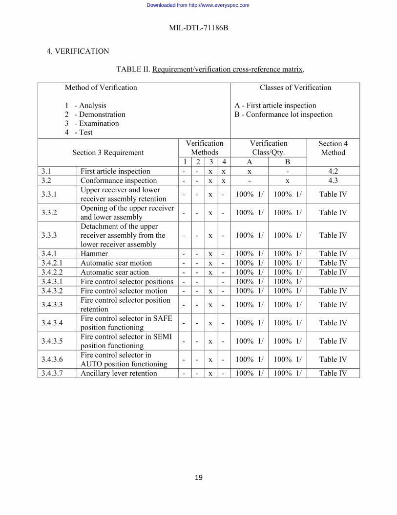
4. VERIFICATION
TABLE II. Requirement/verification cross-reference matrix.
Method of Verification 1 - Analysis 2 - Demonstration 3 - Examination 4 - Test
Classes of Verification
A - First article inspection B - Conformance lot inspection
Section 3 Requirement Verification
Methods Verification Class/Qty.
Section 4 Method
1 2 3 4 A B 3.1 First article inspection - - x x x - 4.2 3.2 Conformance inspection - - x x - x 4.3
3.3.1 Upper receiver and lower receiver assembly retention - - x - 100% 1/ 100% 1/ Table IV
3.3.2 Opening of the upper receiver and lower assembly - - x - 100% 1/ 100% 1/ Table IV
3.3.3 Detachment of the upper receiver assembly from the lower receiver assembly
- - x - 100% 1/ 100% 1/ Table IV
3.4.1 Hammer - - x - 100% 1/ 100% 1/ Table IV 3.4.2.1 Automatic sear motion - - x - 100% 1/ 100% 1/ Table IV 3.4.2.2 Automatic sear action - - x - 100% 1/ 100% 1/ Table IV 3.4.3.1 Fire control selector positions - - - 100% 1/ 100% 1/ 3.4.3.2 Fire control selector motion - - x - 100% 1/ 100% 1/ Table IV
3.4.3.3 Fire control selector position retention - - x - 100% 1/ 100% 1/ Table IV
3.4.3.4 Fire control selector in SAFE position functioning - - x - 100% 1/ 100% 1/ Table IV
3.4.3.5 Fire control selector in SEMI position functioning - - x - 100% 1/ 100% 1/ Table IV
3.4.3.6 Fire control selector in AUTO position functioning - - x - 100% 1/ 100% 1/ Table IV
3.4.3.7 Ancillary lever retention - - x - 100% 1/ 100% 1/ Table IV
Downloaded from http://www.everyspec.com
MIL-DTL-71186B
20
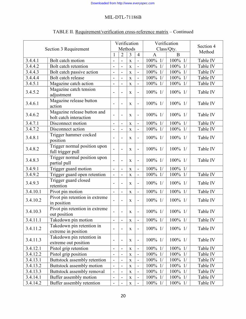
TABLE II. Requirement/verification cross-reference matrix – Continued
Section 3 Requirement Verification
Methods Verification Class/Qty. Section 4
Method 1 2 3 4 A B 3.4.4.1 Bolt catch motion - - x - 100% 1/ 100% 1/ Table IV 3.4.4.2 Bolt catch retention - - x - 100% 1/ 100% 1/ Table IV 3.4.4.3 Bolt catch passive action - - x - 100% 1/ 100% 1/ Table IV 3.4.4.4 Bolt catch release - - x - 100% 1/ 100% 1/ Table IV 3.4.5.1 Magazine catch action - - x - 100% 1/ 100% 1/ Table IV
3.4.5.2 Magazine catch tension adjustment - - x - 100% 1/ 100% 1/ Table IV
3.4.6.1 Magazine release button action - - x - 100% 1/ 100% 1/ Table IV
3.4.6.2 Magazine release button and bolt catch interaction - - x - 100% 1/ 100% 1/ Table IV
3.4.7.1 Disconnect motion - - x - 100% 1/ 100% 1/ Table IV 3.4.7.2 Disconnect action - - x - 100% 1/ 100% 1/ Table IV
3.4.8.1 Trigger hammer cocked position - - x - 100% 1/ 100% 1/ Table IV
3.4.8.2 Trigger normal position upon full trigger pull - - x - 100% 1/ 100% 1/ Table IV
3.4.8.3 Trigger normal position upon partial pull - - x - 100% 1/ 100% 1/ Table IV
3.4.9.1 Trigger guard motion - - x - 100% 1/ 100% 1/ 3.4.9.2 Trigger guard open retention - - x - 100% 1/ 100% 1/ Table IV
3.4.9.3 Trigger guard closed retention - - x - 100% 1/ 100% 1/ Table IV
3.4.10.1 Pivot pin motion - - x - 100% 1/ 100% 1/ Table IV
3.4.10.2 Pivot pin retention in extreme in position - - x - 100% 1/ 100% 1/ Table IV
3.4.10.3 Pivot pin retention in extreme out position - - x - 100% 1/ 100% 1/ Table IV
3.4.11.1 Takedown pin motion - - x - 100% 1/ 100% 1/ Table IV
3.4.11.2 Takedown pin retention in extreme in position - - x - 100% 1/ 100% 1/ Table IV
3.4.11.3 Takedown pin retention in extreme out position - - x - 100% 1/ 100% 1/ Table IV
3.4.12.1 Pistol grip retention - - x - 100% 1/ 100% 1/ Table IV 3.4.12.2 Pistol grip position - - x - 100% 1/ 100% 1/ Table IV 3.4.13.1 Buttstock assembly retention - - x - 100% 1/ 100% 1/ Table IV 3.4.13.2 Buttstock assembly motion - - x - 100% 1/ 100% 1/ Table IV 3.4.13.3 Buttstock assembly removal - - x - 100% 1/ 100% 1/ Table IV 3.4.14.1 Buffer assembly motion - - x - 100% 1/ 100% 1/ Table IV 3.4.14.2 Buffer assembly retention - - x - 100% 1/ 100% 1/ Table IV
Downloaded from http://www.everyspec.com
MIL-DTL-71186B
21
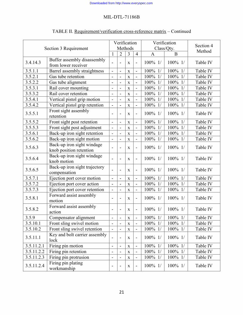
TABLE II. Requirement/verification cross-reference matrix – Continued
Section 3 Requirement Verification
Methods Verification Class/Qty. Section 4
Method 1 2 3 4 A B
3.4.14.3 Buffer assembly disassembly from lower receiver - - x - 100% 1/ 100% 1/ Table IV
3.5.1.1 Barrel assembly straightness - - x - 100% 1/ 100% 1/ Table IV 3.5.2.1 Gas tube retention - - x - 100% 1/ 100% 1/ Table IV 3.5.2.2 Gas tube alignment - - x - 100% 1/ 100% 1/ Table IV 3.5.3.1 Rail cover mounting - - x - 100% 1/ 100% 1/ Table IV 3.5.3.2 Rail cover retention - - x - 100% 1/ 100% 1/ Table IV 3.5.4.1 Vertical pistol grip motion - - x - 100% 1/ 100% 1/ Table IV 3.5.4.2 Vertical pistol grip retention - - x - 100% 1/ 100% 1/ Table IV
3.5.5.1 Front sight assembly retention - - x - 100% 1/ 100% 1/ Table IV
3.5.5.2 Front sight post retention - - x - 100% 1/ 100% 1/ Table IV 3.5.5.3 Front sight post adjustment - - x - 100% 1/ 100% 1/ Table IV 3.5.6.1 Back-up iron sight retention - - x - 100% 1/ 100% 1/ Table IV 3.5.6.2 Back-up iron sight motion - - x - 100% 1/ 100% 1/ Table IV
3.5.6.3 Back-up iron sight windage knob position retention - - x - 100% 1/ 100% 1/ Table IV
3.5.6.4 Back-up iron sight windage knob motion - - x - 100% 1/ 100% 1/ Table IV
3.5.6.5 Back-up iron sight trajectory compensation - - x - 100% 1/ 100% 1/ Table IV
3.5.7.1 Ejection port cover motion - - x - 100% 1/ 100% 1/ Table IV 3.5.7.2 Ejection port cover action - - x - 100% 1/ 100% 1/ Table IV 3.5.7.3 Ejection port cover retention - - x - 100% 1/ 100% 1/ Table IV
3.5.8.1 Forward assist assembly motion - - x - 100% 1/ 100% 1/ Table IV
3.5.8.2 Forward assist assembly action - - x - 100% 1/ 100% 1/ Table IV
3.5.9 Compensator alignment - - x - 100% 1/ 100% 1/ Table IV 3.5.10.1 Front sling swivel motion - - x - 100% 1/ 100% 1/ Table IV 3.5.10.2 Front sling swivel retention - - x - 100% 1/ 100% 1/ Table IV
3.5.11.1 Key and bolt carrier assembly lock - - x - 100% 1/ 100% 1/ Table IV
3.5.11.2.1 Firing pin motion - - x - 100% 1/ 100% 1/ Table IV 3.5.11.2.2 Firing pin retention - - x - 100% 1/ 100% 1/ Table IV 3.5.11.2.3 Firing pin protrusion - - x - 100% 1/ 100% 1/ Table IV
3.5.11.2.4 Firing pin plating workmanship - - x - 100% 1/ 100% 1/ Table IV
Downloaded from http://www.everyspec.com

MIL-DTL-71186B
22
TABLE II. Requirement/verification cross-reference matrix – Continued
Section 3 Requirement Verification
Methods Verification Class/Qty. Section 4
Method 1 2 3 4 A B 3.5.12 Charging handle retention - - x - 100% 1/ 100% 1/ Table IV 3.5.13.1 Bolt assembly motion - - x - 100% 1/ 100% 1/ Table IV 3.5.13.2 Bolt assembly retention - - x - 100% 1/ 100% 1/ Table IV 3.5.13.3.1 Extractor motion - - x - 100% 1/ 100% 1/ Table IV 3.5.13.3.2 Extractor action - - x - 100% 1/ 100% 1/ Table IV 3.5.13.3.3 Extractor retention - - x - 100% 1/ 100% 1/ Table IV 3.5.13.4.1 Ejector motion - - x - 100% 1/ 100% 1/ Table IV 3.5.13.4.2 Ejector action - - x - 100% 1/ 100% 1/ Table IV 3.5.13.4.3 Ejector retention - - x - 100% 1/ 100% 1/ Table IV 3.5.13.5.1 Cam pin motion - - x - 100% 1/ 100% 1/ Table IV 3.5.13.5.2 Cam pin retention - - x - 100% 1/ 100% 1/ Table IV 3.5.13.5.3 Cam pin disassembly - - x - 100% 1/ 100% 1/ Table IV 3.5.13.5.4 Cam pin symmetry - - x - 100% 1/ 100% 1/ Table IV 3.6.1.1 Firing pin indent - - - x 100% 10 /2 4.5.1.1 3.6.1.2 Bolt action indent - - - x 100% 10 /2 4.5.1.2 3.6.1.3 Muzzle down position indent - - - x 100% 10 /2 4.5.1.3 3.6.1.4 Firing pin indent location - - - x 100% 10 /2 4.5.1.4 3.6.1.5 Firing pin protrusion - - - x 100% 10 /2 4.5.1.5 3.6.2.1 Minimum trigger pull - - - x 100% 100% 4.5.2.1 3.6.2.2 Maximum trigger pull - - - x 100% 100% 4.5.2.2 3.6.2.3 Creep - - - x 100% 100% 4.5.2.3 3.6.3.1 High pressure resistance test - - - x 100% 100% 4.5.3.1 3.6.3.2.1 Minimum headspace - - x - 100% 100% 4.5.3.2.1 3.6.3.2.2 Maximum headspace - - x - 100% 100% 4.5.3.2.2 3.6.3.3 Barrel assembly integrity - - - x 100% 100% 4.5.3.3 3.6.3.4 Bolt assembly integrity - - - x 100% 100% 4.5.3.4
3.6.3.5 High pressure test cartridge integrity - - - x 100% 100% 4.5.3.5
3.6.4.1 Function firing semi-automatic - - - x 100% 100% 4.5.4.1
3.6.4.2 Function firing automatic - - - x 100% 100% 4.5.4.2 3.6.5 Cyclic rate of fire - - - x 100% 190 3/ 4.5.5 3.6.6 Targeting and accuracy - - - x 100% 100% 4.5.6 3.6.7.1 Endurance functioning - - - x 4 4/ 4 4/ 4.5.7.1 3.6.7.2 Endurance firing cycle rate - - - x 4 5/ 4 5/ 4.5.7.2
3.6.7.3 Endurance target and accuracy - - - x 4 5/ 4 5/ 4.5.7.3
3.6.7.4 Endurance barrel assembly integrity - - - x 4 5/ 4 5/ 4.5.7.4
Downloaded from http://www.everyspec.com

MIL-DTL-71186B
23
TABLE II. Requirement/verification cross-reference matrix – Continued
Section 3 Requirement Verification
Methods Verification Class/Qty. Section 4
Method 1 2 3 4 A B
3.6.7.5 Endurance bolt assembly integrity - - - x 4 5/ 4 5/ 4.5.7.5
3.6.7.6 Endurance headspace measurement - - - x 4 5/ 4 5/ 4.5.7.6
3.6.7.7 Endurance bolt action indent - - - x 4 5/ 4 5/ 4.5.7.7
3.6.7.8 Endurance muzzle down position indent - - - x 4 5/ 4 5/ 4.5.7.8
3.6.7.9 Endurance firing pin indent location - - - x 4 5/ 4 5/ 4.5.7.9
3.6.7.10 Endurance firing pin protrusion - - - x 4 5/ 4 5/ 4.4.7.10
3.6.8 Interchangeability - - - x 10 2/ 10 2/ 4.5.8 3.6.9 Unique Identification (UID) - - - x 100% 100% 4.5.9 3.6.10 Workmanship - - - x 100% 100% 4.5.10 Notes:
1/ Per 4.2 and 4.3 the results of verification 4.4 shall be used to provide supporting information for this requirement. 2/ Test ten (10) - Accept with zero (0) failures - Reject with one (1) failure. Not applicable for 100% inspections. 3/ The cyclic rate of fire shall be tested on each weapon, until 190 consecutive weapons meet the requirement. If the consecutive weapons meet the requirement, then the cyclic rate of fire shall be tested on every 10th weapon (i.e., sampling shall apply). If a weapon fails to meet the requirement during sampling, then the other 9 weapons shall be tested. If the other 9 weapons meet the requirement, then sampling shall continue. However, if any of the other 9 weapons fails to meet the requirements or a new First Article is required, then testing of 190 consecutive weapons shall be reinstated before returning to sampling. 4/ Two (2) weapons which have been through the interchange tests and two (2) weapons which have not been through the interchange tests shall be used for this verification. 5/ Weapons from the endurance functioning test shall be used for this test.
4.1 Classification of inspections. The inspection requirements specified herein are classified
as follows: a. First article inspection (see 4.2). b. Conformance inspection (see 4.3).
4.2 First article inspection. When specified, a sample of the weapon shall be subjected to all
Downloaded from http://www.everyspec.com

MIL-DTL-71186B
24
tests in Table II. For requirements 3.3.1 through 3.5.13.5.4, Table IV provides rejection criteria and verification.
4.2.1 First article sample. The first article sample shall be representative of the
manufacturing methods and processes to be used for quantity production. The first articles shall consist of the quantities specified in Table III unless otherwise specified.
TABLE III. First article sample lot size.
NOMENCLATURE DRAWING QUANTITY
M4A1 Carbine 12972700 12
4.2.2 First article rejection. If any weapon fails to comply with any of the first article requirements or any drawing requirements, the first article sample shall be rejected.
4.2.2.1 First article rejection examination. Any non-conforming weapon shall be inspected
by performing a dimensional, physical, and visual examination, as required, of the weapon and magazine component that are suspected to be the cause of the test failure.
4.3 Conformance inspection. Unless otherwise specified, all weapons shall be subjected to
all tests in the order specified in Table II. For requirements 3.3.1 through 3.5.13.5.4, Table IV provides rejection criteria and verification.
4.3.1 Lot size. Unless otherwise specified, an inspection lot shall initially consist of 1,000
weapons or a single month’s production, whichever is smaller (see 6.7 and 6.8).
4.3.1.1 Inspection lot formation. The formation and presentation of inspection lots shall be in accordance with MIL-STD-1916.
4.3.2 Lot identification. Each inspection lot shall be identified with a lot number. When a
rejected inspection lot is resubmitted after reconditioning, it shall be identified as such.
4.3.3 Conformance procedures. Conformance inspections and tests are specified in the requirement/verification cross-reference matrix, Table II.
4.3.4 Conformance lot inspection rejection. If any weapon fails to comply with any of the
conformance lot inspection requirements or any drawing requirements, the inspection lot shall be rejected.
4.3.4.1 Conformance lot inspection rejection examination. Any non-conforming weapon
shall be inspected by performing a dimensional, physical, and visual examination, as required, of the weapon and magazine component that are suspected to be the cause of the test failure
Downloaded from http://www.everyspec.com
MIL-DTL-71186B
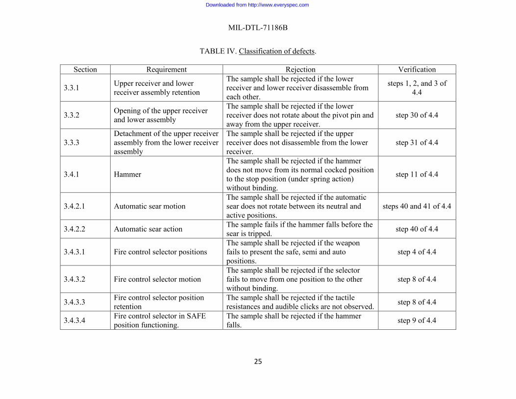
25
TABLE IV. Classification of defects.
Section Requirement Rejection Verification
3.3.1 Upper receiver and lower receiver assembly retention
The sample shall be rejected if the lower receiver and lower receiver disassemble from each other.
steps 1, 2, and 3 of 4.4
3.3.2 Opening of the upper receiver and lower assembly
The sample shall be rejected if the lower receiver does not rotate about the pivot pin and away from the upper receiver.
step 30 of 4.4
3.3.3 Detachment of the upper receiver assembly from the lower receiver assembly
The sample shall be rejected if the upper receiver does not disassemble from the lower receiver.
step 31 of 4.4
3.4.1 Hammer
The sample shall be rejected if the hammer does not move from its normal cocked position to the stop position (under spring action) without binding.
step 11 of 4.4
3.4.2.1 Automatic sear motion The sample shall be rejected if the automatic sear does not rotate between its neutral and active positions.
steps 40 and 41 of 4.4
3.4.2.2 Automatic sear action The sample fails if the hammer falls before the sear is tripped. step 40 of 4.4
3.4.3.1 Fire control selector positions The sample shall be rejected if the weapon fails to present the safe, semi and auto positions.
step 4 of 4.4
3.4.3.2 Fire control selector motion The sample shall be rejected if the selector fails to move from one position to the other without binding.
step 8 of 4.4
3.4.3.3 Fire control selector position retention
The sample shall be rejected if the tactile resistances and audible clicks are not observed. step 8 of 4.4
3.4.3.4 Fire control selector in SAFE position functioning.
The sample shall be rejected if the hammer falls. step 9 of 4.4
Downloaded from http://www.everyspec.com
MIL-DTL-71186B
26
TABLE IV. Classification of defects – Continued. Section Requirement Rejection Verification
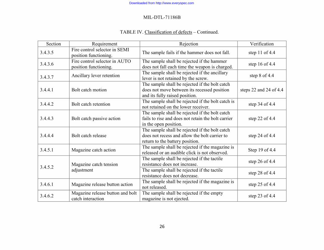
3.4.3.5 Fire control selector in SEMI position functioning. The sample fails if the hammer does not fall. step 11 of 4.4
3.4.3.6 Fire control selector in AUTO position functioning.
The sample shall be rejected if the hammer does not fall each time the weapon is charged. step 16 of 4.4
3.4.3.7 Ancillary lever retention The sample shall be rejected if the ancillary lever is not retained by the screw. step 8 of 4.4
3.4.4.1 Bolt catch motion The sample shall be rejected if the bolt catch does not move between its recessed position and its fully raised position.
steps 22 and 24 of 4.4
3.4.4.2 Bolt catch retention The sample shall be rejected if the bolt catch is not retained on the lower receiver. step 34 of 4.4
3.4.4.3 Bolt catch passive action The sample shall be rejected if the bolt catch fails to rise and does not retain the bolt carrier in the open position.
step 22 of 4.4
3.4.4.4 Bolt catch release The sample shall be rejected if the bolt catch does not recess and allow the bolt carrier to return to the battery position.
step 24 of 4.4
3.4.5.1 Magazine catch action The sample shall be rejected if the magazine is released or an audible click is not observed. Step 19 of 4.4
3.4.5.2 Magazine catch tension adjustment
The sample shall be rejected if the tactile resistance does not increase. step 26 of 4.4
The sample shall be rejected if the tactile resistance does not decrease. step 28 of 4.4
3.4.6.1 Magazine release button action The sample shall be rejected if the magazine is not released. step 25 of 4.4
3.4.6.2 Magazine release button and bolt catch interaction
The sample shall be rejected if the empty magazine is not ejected. step 23 of 4.4
Downloaded from http://www.everyspec.com
MIL-DTL-71186B
27
TABLE IV. Classification of defects – Continued Section Requirement Rejection Verification
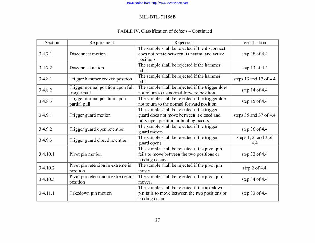
3.4.7.1 Disconnect motion The sample shall be rejected if the disconnect does not rotate between its neutral and active positions.
step 38 of 4.4
3.4.7.2 Disconnect action The sample shall be rejected if the hammer falls. step 13 of 4.4
3.4.8.1 Trigger hammer cocked position The sample shall be rejected if the hammer falls. steps 13 and 17 of 4.4
3.4.8.2 Trigger normal position upon full trigger pull
The sample shall be rejected if the trigger does not return to its normal forward position. step 14 of 4.4
3.4.8.3 Trigger normal position upon partial pull
The sample shall be rejected if the trigger does not return to the normal forward position. step 15 of 4.4
3.4.9.1 Trigger guard motion The sample shall be rejected if the trigger guard does not move between it closed and fully open position or binding occurs.
steps 35 and 37 of 4.4
3.4.9.2 Trigger guard open retention The sample shall be rejected if the trigger guard moves. step 36 of 4.4
3.4.9.3 Trigger guard closed retention The sample shall be rejected if the trigger guard opens.
steps 1, 2, and 3 of 4.4
3.4.10.1 Pivot pin motion The sample shall be rejected if the pivot pin fails to move between the two positions or binding occurs.
step 32 of 4.4
3.4.10.2 Pivot pin retention in extreme in position
The sample shall be rejected if the pivot pin moves. step 2 of 4.4
3.4.10.3 Pivot pin retention in extreme out position
The sample shall be rejected if the pivot pin moves. step 34 of 4.4
3.4.11.1 Takedown pin motion The sample shall be rejected if the takedown pin fails to move between the two positions or binding occurs.
step 33 of 4.4
Downloaded from http://www.everyspec.com

MIL-DTL-71186B
28
TABLE IV. Classification of defects – Continued. Section Requirement Rejection Verification
3.4.11.2 Takedown pin retention in extreme in position
The sample shall be rejected if the takedown pin moves. step 2 of 4.4
3.4.11.3 Takedown pin retention in extreme out position
The sample shall be rejected if the takedown pin moves. step 34 of 4.4
3.4.12.1 Pistol grip retention The sample shall be rejected if the pistol grip detaches from the lower receiver.
steps 1, 2, and 3 of 4.4
3.4.12.2 Pistol grip position The sample shall be rejected if the pistol grip interferes with the fire control selector motion. step 8 of 4.4
3.4.13.1
Buttstock assembly retention
The sample shall be rejected if the release lever is not securely retained on the buttstock assembly and subjected to continuous pressure from the locking spring.
step 47 of 4.4
The sample shall be rejected if the buttstock assembly rotates about the receiver extension. step 52 of 4.4
The sample shall be rejected if forward or rearward movement is detected beyond the extended and retracted positions.
steps 47 through 51 of 4.4
3.4.13.2 Buttstock assembly motion
The sample shall be rejected if the buttstock assembly either fails to move between the retracted and extended positions or is allowed to move beyond the extended position.
step 47 of 4.4
3.4.13.3 Buttstock assembly removal The sample shall be rejected if the buttstock assembly fails to disassemble from the receiver extension
step 53 of 4.4
Downloaded from http://www.everyspec.com

MIL-DTL-71186B
29
TABLE IV. Classification of defects – Continued Section Requirement Rejection Verification
3.4.14.1 Buffer assembly motion
The sample shall be rejected if the buffer assembly fails to move between the retained and the fully compressed positions or binding occurs. The sample shall fail if movement from compressed to retained is not caused by spring action.
step 47 of 4.4
3.4.14.2 Buffer assembly retention The sample shall be rejected if the buffer assembly detaches from the lower receiver. step 44 of 4.4
3.4.14.3 Buffer assembly disassembly from lower receiver
The sample shall fail if the buffer assembly fails to disassemble from the lower receiver. step 45 of 4.4
3.5.1.1 Barrel assembly straightness The sample shall be rejected if the bore straightness gage does not pass freely through the bore, when dropped from the chamber end.
step 87 of 4.4
3.5.2.1 Gas tube retention The sample shall be rejected if the gas tube is not retained in the front sight assembly. step 1 of 4.4
3.5.2.2 Gas tube alignment The sample shall be rejected if the gas tube hits the bolt carrier key, or if the gas tube binds in the bolt carrier key.
step 68 of 4.4
3.5.3.1 Rail cover mounting The sample shall be rejected if the rail covers do not slide on and off the rail adaptor system when the retaining clips are depressed.
step 61 of 4.4
3.5.3.2 Rail cover retention The sample shall be rejected if the rail covers disassemble from the rail adaptor system.
steps 1, 2, and 3 of 4.4
3.5.4.1 Vertical pistol grip motion The sample shall be rejected if the vertical pistol grip does not move from one end to the other of the rail cover or binding occurs.
step 59 of 4.4
Downloaded from http://www.everyspec.com

MIL-DTL-71186B
30
TABLE IV. Classification of defects – Continued Section Requirement Rejection Verification
3.5.4.2 Vertical pistol grip retention The sample shall be rejected if the vertical pistol grip disassembles from the rail adaptor system.
steps 1, 2, and 3 of 4.4
3.5.5.1 Front sight assembly retention The sample shall be rejected if the front sight assembly disassembles from the barrel.
steps 1, 2, and 3 of 4.4
3.5.5.2 Front sight post retention The sample shall be rejected if the front sight post disassembles from the front sight assembly.
steps 1, 2, and 3 of 4.4
3.5.5.3 Front sight post adjustment The sample shall be rejected if the front sight post does not lower or less than 16 clicks are observed.
step 58 of 4.4
3.5.6.1 Back-up iron sight retention The sample shall be rejected if the back-up iron sight disassembles from the upper receiver.
steps 1, 2, and 3 of 4.4
3.5.6.2 Back-up iron sight motion The sample shall be rejected if the rear sight does not pivot to a full vertical position. step 63 of 4.4
3.5.6.3 Back-up iron sight windage knob position retention
The sample shall be rejected if the windage knob changes position.
steps 1, 2, and 3 of 4.4
3.5.6.4 Back-up iron sight windage knob motion
The sample shall be rejected if the back-up iron sight does not move from extreme left to extreme right (after 7 complete revolutions) or binding occurs.
step 64 of 4.4
3.5.6.5 Back-up iron sight trajectory compensation
The sample shall be rejected if the rear sight does not elevate. step 65 of 4.4
3.5.7.1 Ejection port cover motion The sample shall be rejected if the ejection port cover fails to move between the closed and open positions or binding occurs.
step 6 of 4.4
Downloaded from http://www.everyspec.com

MIL-DTL-71186B
31
TABLE IV. Classification of defects – Continued Section Requirement Rejection Verification
3.5.7.2 Ejection port cover action
The sample shall fail if the ejection port cover fails to open (Rearward) step 5 of 4.4
The sample shall fail if the ejection port cover fails to open (Forward) step 7 of 4.4
3.5.7.3 Ejection port cover retention The sample shall be rejected if the ejection port cover fails to stay closed.
steps 1, 2, and 3 of 4.4
3.5.8.1 Forward assist assembly motion
The sample shall be rejected if the forward assist assembly fails to engage the bolt carrier or fails to return, under spring action, to its fully outward position.
step 54 of 4.4
3.5.8.2 Forward assist assembly action The sample shall be rejected if the bolt carrier fails to reach the battery position. step 55 of 4.4
3.5.9 Compensator alignment The sample shall be rejected if no portion of the middle slot coincides with TDC line. step 56 of 4.4
3.5.10.1 Front sling swivel motion The sample shall be rejected if the front swivel does not move from between its forward position and rear position or binding occurs.
step 57 of 4.4
3.5.10.2 Front sling swivel retention The sample shall be rejected if the front swivel disassembles from the front sight assembly.
steps 1, 2, and 3 of 4.4
3.5.11.1 Key and bolt carrier assembly lock
The sample shall be rejected if the key and bolt assembly does not lock. step 67 of 4.4
3.5.11.2.1 Firing pin motion The sample shall be rejected if the firing pin does not move from its recessed position to a maximum protrusion of 0.028 inches.
step 71 of 4.4
3.5.11.2.2 Firing pin retention The sample shall be rejected if the firing pin disassembles from the bolt assembly. step 70 of 4.4
3.5.11.2.3 Firing pin protrusion The sample shall fail if the firing pin protrusion is greater than 0.036 in or less than 0.0028 in.
step 72 of 4.4
Downloaded from http://www.everyspec.com

MIL-DTL-71186B
32
TABLE IV. Classification of defects – Continued Section Requirement Rejection Verification
3.5.11.2.4 Firing pin plating workmanship
The sample shall be rejected if the plating shows evidence of nodules, flaking, stripping, anode burns and evidence of etched base steel, except as specified on the applicable Drawing 8448503.
step 79 of 4.4
3.5.12 Charging handle retention The sample shall be rejected if the charging handle moves without pressing the charging handle release.
step 3 of 4.4
3.5.13.1 Bolt assembly motion The sample shall be rejected if the key and bolt assembly does not lock. steps 67 and 78 of 4.4
3.5.13.2 Bolt assembly retention The sample shall be rejected if the bolt assembly detaches from the bolt carrier assembly.
step 76 of 4.4
3.5.13.3.1 Extractor motion The sample shall be rejected if the extractor fails to move between its rest and active positions or binding occurs.
step 21 of 4.4
3.5.13.3.2 Extractor action The sample shall be rejected if the dummy cartridge is not extracted from the chamber. step 21 of 4.4
3.5.13.3.3 Extractor retention The sample shall be rejected if the extractor disassembles from the bolt carrier assembly step 83 of 4.4
3.5.13.4.1 Ejector motion The sample shall be rejected if the ejector fails to move between its recessed and raised positions or binding occurs.
step 21 of 4.4
3.5.13.4.2 Ejector action The sample shall be rejected if the dummy cartridge is not ejected from the weapon. step 21 of 4.4
3.5.13.4.3 Ejector retention The sample shall be rejected if the ejector disassembles from the bolt assembly. step 82 of 4.4
Downloaded from http://www.everyspec.com

MIL-DTL-71186B
33
TABLE IV. Classification of defects – Continued Section Requirement Rejection Verification
3.5.13.5.1 Cam pin motion The sample shall be rejected if the cam pin
fails to move through the cam pin area causing the bolt carrier assembly to lock.
steps 73 and 75 of 4.4
3.5.13.5.2 Cam pin retention The sample shall be rejected if the cam pin disassembles from the bolt carrier assembly. step 74 of 4.4
3.5.13.5.3 Cam pin disassembly The sample shall be rejected if the cam pin does not disassemble from the bolt carrier
assembly without removing the key. step 80 of 4.4
3.5.13.5.4 Cam pin symmetry The sample shall be rejected if the bolt carrier does not lock. step 86 of 4.4
Downloaded from http://www.everyspec.com

MIL-DTL-71186B
34
4.4 Weapon sequential verification procedure.
a. Setup: Weapon shall be fully assembled with rail covers, vertical pistol grip and backup iron sight securely retained. Ejection port cover shall be in the closed position. No magazine shall be installed. Bolt assembly shall be in the battery position (see 6.10.11). Hammer shall be in the cocked position. The fire control selector shall be at the “SAFE” position. The weapon shall be clear of ammunition. Weapon shall be zeroed per the Operator’s Manual 9-1005-319-10.
b. Verification shall be performed as follows: 1. Hold the weapon in the muzzle up position with its ejection port perpendicular to the
floor. No components shall disassemble from the weapon during this step. No restrained components shall move from their restrained position during this step. Pay special attention that the gas tube has not been released.
2. Hold the weapon with its ejection port parallel to and facing the floor. No
components shall disassemble from the weapon during this step. No restrained components shall move from their restrained position during this step.
3. Hold the weapon in the muzzle down position with its ejection port perpendicular to
the floor. No components shall disassemble from the weapon during this step. No restrained components shall move from their restrained position during this step.
4. Visually examine the lower receiver for the presence of a fire control selector with
three positions; SAFE, SEMI and AUTO.
5. Pull charging handle assembly to the rear and hold. The ejection port cover shall open. (Ejection port cover action – rearward)
6. Once released, the ejection port cover shall come to rest against the lower receiver under spring action. There shall be no binding. (Ejection port cover motion) Manually rotate the ejection port cover to the closed position. There shall be no binding. (Ejection port cover motion)
7. Release the charging handle. The ejection port cover shall open. (Ejection port cover action – forward)
8. Using either the main lever or the ancillary lever, once each, manually rotate the fire
control selector from “SAFE”, to “SEMI”, to “AUTO”, to “SEMI”, and then to the “SAFE” position. There shall be no binding. A tactile resistance and an audible click shall be observed when arriving and achieving each position, respectively. (Fire control selector motion and position retention) Ensure that the pistol grip does not interfere with the fire control selector motion. (Pistol grip position) The ancillary lever shall be securely retained by the screw. (Ancillary lever retention)
Downloaded from http://www.everyspec.com

MIL-DTL-71186B
35
9. Pull the trigger. The hammer shall not fall (see 6.10.6). (Fire control selector in SAFE position functioning)
10. Place the fire control selector in the “SEMI” position. Charge (see 6.10.7) the
weapon. The hammer shall not fall.
11. Pull the trigger and hold to the rear. The hammer shall fall (see 6.10.5). (Fire control selector in SEMI position functioning, hammer)
12. Charge the weapon.
13. The hammer shall not fall. (Disconnect action) Slowly (¼ to ½ the rate of normal
trigger release) release the trigger until the trigger is fully forward. An audible click shall be heard as the hammer transfers from the disconnect to the trigger. The hammer shall not fall. (Trigger hammer cocked position)
14. Pull the trigger and hold to the rear. Charge the weapon then release the trigger. The
trigger shall return to its normal position. (Trigger normal position upon full trigger pull)
15. Partially pull the trigger and release. The trigger shall return to its normal position.
(Trigger normal position upon partial trigger pull)
16. Place the fire control selector in the “AUTO” position. Pull the trigger and hold to the rear again. The hammer shall fall. Charge the weapon five times. The hammer shall fall each time the weapon is charged. (Fire control selector in AUTO position functioning)
17. Release the trigger.
18. Place the fire control selector in the "SEMI" position.
19. Insert a magazine with one M199A1E1, 5.56mm dummy cartridge in accordance with
Drawing 13068236 or commercial equivalent conforming to SAAMI-Z299.4 into the weapon until an audible click is heard. Once the click is heard, apply downward pressure on the magazine. The magazine shall not be released. (Magazine catch action)
20. Charge the weapon. The dummy cartridge shall be stripped from the magazine.
21. Pull the charging handle to the rear and hold to the rear. The dummy cartridge shall
be extracted and then ejected. (Extractor action, extractor motion, ejector action, ejector motion)
22. The bolt catch shall rise as the now empty magazine’s magazine follower engages
and raises the bolt catch. Release the charging handle. The bolt catch shall retain the
Downloaded from http://www.everyspec.com

MIL-DTL-71186B
36
bolt carrier assembly. (Bolt catch passive action, bolt catch motion – raised)
23. Press and hold the magazine release button. The magazine shall be ejected. (Magazine release and bolt catch interaction)
24. Press the bolt catch release. The bolt catch shall move to its receded position. The
bolt shall return to the battery position. (Bolt catch release, bolt catch motion – recessed)
25. Insert an empty magazine into the weapon and observe the tactile resistance that is
felt when overcoming the magazine catch (instrumentation may be used to measure this). Press the magazine release. The magazine shall be released. (Magazine release button action).
26. Press in on the magazine catch button until the left side of the magazine catch button
sticks out beyond the receiver. Rotate the magazine catch clockwise. Release the magazine catch button. Re-insert the empty magazine into the weapon and observe the tactile resistance that is felt when overcoming the magazine catch. The tactile resistance shall be harder to overcome than before (instrumentation may be used to measure this). (Magazine catch tension adjustment – increase)
27. Press the magazine release. The magazine shall be released.
28. Press in on the magazine catch button until the left side of the magazine catch button
sticks out beyond the receiver. Rotate the magazine catch counter clockwise. Release the magazine catch button. Re-insert the empty magazine into the weapon and observe the tactile resistance that is felt when overcoming the magazine catch. The tactile resistance shall be easier to overcome than before (instrumentation may be used to measure this). (Magazine catch tension adjustment – decrease)
29. Press the magazine release. The magazine shall be released.
30. The takedown pin shall be moved to its extreme out position. While holding the
upper receiver, apply a downward pressure to the pistol grip. The lower receiver shall rotate about the pivot pin opening the upper and lower receiver assembly. (Opening of the upper receiver and lower receiver assembly)
31. The pivot pin shall be moved to its extreme out position. Pull the lower receiver
assembly away from the upper receiver assembly. The receivers shall detach from each other. (Detachment of the upper receiver assembly from the lower receiver assembly)
32. Move the pivot pin from its extreme out position to its extreme in position. There
shall be no binding. Move the pivot pin from its extreme in position to its extreme out position. There shall be no binding. (Pivot pin motion)
Downloaded from http://www.everyspec.com
MIL-DTL-71186B
37
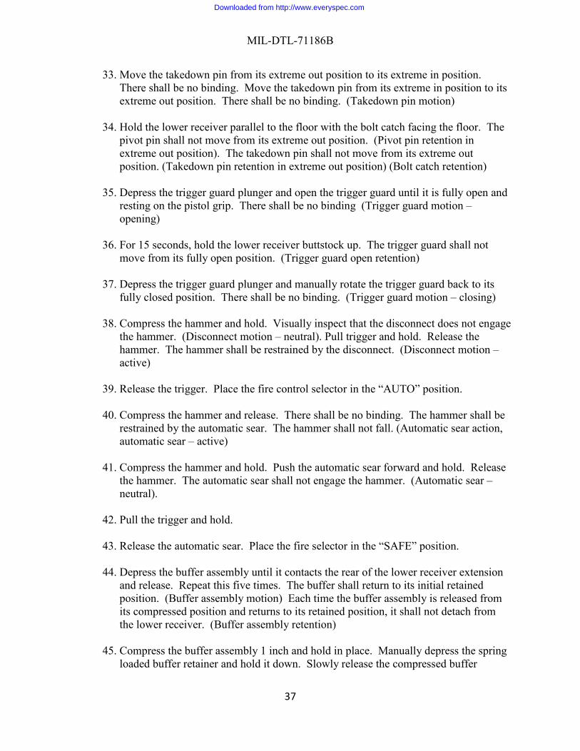
33. Move the takedown pin from its extreme out position to its extreme in position. There shall be no binding. Move the takedown pin from its extreme in position to its extreme out position. There shall be no binding. (Takedown pin motion)
34. Hold the lower receiver parallel to the floor with the bolt catch facing the floor. The
pivot pin shall not move from its extreme out position. (Pivot pin retention in extreme out position). The takedown pin shall not move from its extreme out position. (Takedown pin retention in extreme out position) (Bolt catch retention)
35. Depress the trigger guard plunger and open the trigger guard until it is fully open and
resting on the pistol grip. There shall be no binding (Trigger guard motion – opening)
36. For 15 seconds, hold the lower receiver buttstock up. The trigger guard shall not move from its fully open position. (Trigger guard open retention)
37. Depress the trigger guard plunger and manually rotate the trigger guard back to its fully closed position. There shall be no binding. (Trigger guard motion – closing)
38. Compress the hammer and hold. Visually inspect that the disconnect does not engage
the hammer. (Disconnect motion – neutral). Pull trigger and hold. Release the hammer. The hammer shall be restrained by the disconnect. (Disconnect motion – active)
39. Release the trigger. Place the fire control selector in the “AUTO” position.
40. Compress the hammer and release. There shall be no binding. The hammer shall be
restrained by the automatic sear. The hammer shall not fall. (Automatic sear action, automatic sear – active)
41. Compress the hammer and hold. Push the automatic sear forward and hold. Release the hammer. The automatic sear shall not engage the hammer. (Automatic sear – neutral).
42. Pull the trigger and hold.
43. Release the automatic sear. Place the fire selector in the “SAFE” position.
44. Depress the buffer assembly until it contacts the rear of the lower receiver extension
and release. Repeat this five times. The buffer shall return to its initial retained position. (Buffer assembly motion) Each time the buffer assembly is released from its compressed position and returns to its retained position, it shall not detach from the lower receiver. (Buffer assembly retention)
45. Compress the buffer assembly 1 inch and hold in place. Manually depress the spring
loaded buffer retainer and hold it down. Slowly release the compressed buffer
Downloaded from http://www.everyspec.com

MIL-DTL-71186B
38
assembly until it overcomes the spring loaded buffer retainer position and disassembles from the lower receiver. (Buffer assembly disassembly)
46. Manually depress the spring loaded buffer retainer and hold it down. Slowly insert
the buffer assembly until it overcomes the spring loaded buffer retainer position. Release the spring loaded buffer retainer. Release the buffer assembly. It shall be retained.
47. Ensure that the release lever is securely retained on the buttstock assembly and
subjected to continuous pressure from the locking spring. When the release lever is depressed, the buttstock assembly shall be free to slide on the receiver extension between the extended and retracted positions but shall not move beyond the extended position (i.e., be removed). Depress the release lever and slide the buttstock assembly to the retracted position and back to the extended position. There shall be no binding. (Buttstock assembly retention/motion)
48. Depress the release lever and move the buttstock assembly into the retracted position.
Release the release lever. Manually attempt to push the buttstock assembly towards the lower receiver (hold firmly in place). There shall be no forward movement of the buttstock assembly. (Buttstock assembly retention – retracted – forward)
49. Manually attempt to pull the buttstock assembly away from the lower receiver. There
shall be no rearward movement of the buttstock assembly. (Buttstock assembly retention – retracted – rearward)
50. Depress the release lever and move the buttstock assembly into the extended position.
Release the release lever. Manually attempt to push the buttstock assembly towards the lower receiver (hold firmly in place). There shall be no forward movement of the buttstock assembly. (Buttstock assembly retention – extended – forward)
51. Manually attempt to pull the buttstock assembly away from the lower receiver. There
shall be no rearward movement of the buttstock assembly. (Buttstock assembly retention – extended – rearward)
52. Manually attempt to rotate the buttstock assembly around the receiver extension.
(Buttstock assembly retention – rotation) 53. Depress the release lever and pull the buttstock assembly rearward off of the receiver
extension. (Buttstock assembly removal) Install the buttstock assembly to the weapon.
54. Ensure that the bolt carrier assembly is in the battery position. Depress the forward
assist assembly until the pawl engages the bolt carrier. Release the forward assist assembly. The forward assist shall return, under spring action, to its fully outward position. The pawl shall now be disengaged from the bolt carrier. (Forward assist assembly motion)
Downloaded from http://www.everyspec.com

MIL-DTL-71186B
39
55. Using the charging handle assembly, retract the bolt carrier assembly about one-
fourth of an inch, as determined from the front of the bolt carrier to the front of the receiver ejection port. Repeatedly depress and release the forward assist assembly until the bolt carrier progresses to the battery position. (Forward assist assembly action)
56. Visually inspect that some portion of the compensator’s third slot (middle slot) aligns
with the Top Dead Center (TDC). (Compensator alignment) 57. Manually rotate the front swivel between its forward position to its rear position and
back. There shall be no binding. (Front sling swivel motion)
58. Depress the front sight detent and turn the front sight post clockwise. The front sight post shall lower. The detent shall pop into the next front sight post slot. Depress the front sight detent and turn the front sight post clockwise 15 more times. Each time the front sight post is turned the front sight post shall lower. (Front sight post adjustment). Return the front sight post to its original position.
59. Unlock the vertical pistol grip from the rail adaptor system. Slide the vertical pistol
grip all the way forward and all the way back on the rail. There shall be no binding. (Vertical pistol grip motion)
60. Remove the vertical pistol grip from the weapon.
61. For each rail cover, depress its retaining clip and slide it off the rail adaptor system.
For each rail cover, depress its retaining clip and slide it onto the appropriate rail until the retaining clip automatically engages, locking the rail cover in place. (Rail cover mounting)
62. Install the vertical pistol grip to the weapon.
63. Rotate the windage knob to move the rear sight to the extreme left. The rear sight shall pivot to the full vertical position under spring action. Rotate the windage knob to move the rear sight to the extreme right. The rear sight shall pivot to the full vertical position under spring action. (Back-up iron sight motion)
64. Rotate the windage knob seven complete revolutions, moving the rear sight from the
extreme left to the extreme right without binding. (Back-up iron sight windage knob motion)
65. Elevate the rear sight by means of the sight cam, to compensate for trajectory for
ranges from 200 meters to 600 meters. (Back-up iron sight trajectory compensation)
66. Hold the upper receiver muzzle down. Pull the charging handle to the rear. Hold the bolt carrier assembly to the rear and push charging handle forward.
Downloaded from http://www.everyspec.com
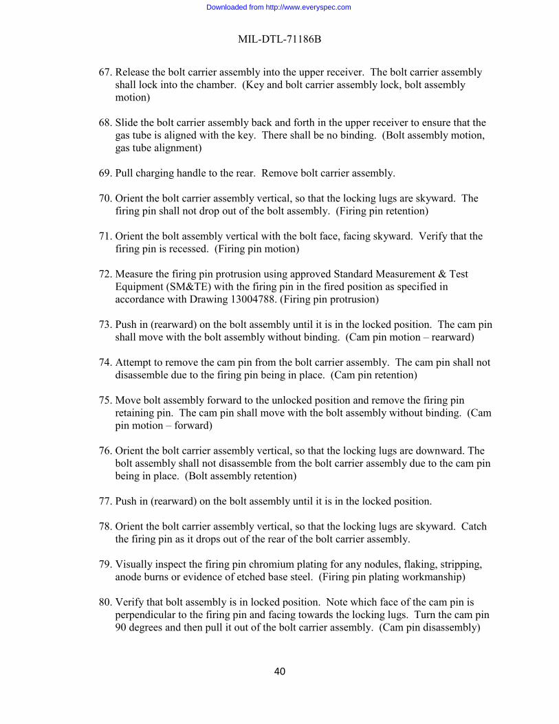
MIL-DTL-71186B
40
67. Release the bolt carrier assembly into the upper receiver. The bolt carrier assembly shall lock into the chamber. (Key and bolt carrier assembly lock, bolt assembly motion)
68. Slide the bolt carrier assembly back and forth in the upper receiver to ensure that the
gas tube is aligned with the key. There shall be no binding. (Bolt assembly motion, gas tube alignment)
69. Pull charging handle to the rear. Remove bolt carrier assembly.
70. Orient the bolt carrier assembly vertical, so that the locking lugs are skyward. The
firing pin shall not drop out of the bolt assembly. (Firing pin retention) 71. Orient the bolt assembly vertical with the bolt face, facing skyward. Verify that the
firing pin is recessed. (Firing pin motion) 72. Measure the firing pin protrusion using approved Standard Measurement & Test
Equipment (SM&TE) with the firing pin in the fired position as specified in accordance with Drawing 13004788. (Firing pin protrusion)
73. Push in (rearward) on the bolt assembly until it is in the locked position. The cam pin
shall move with the bolt assembly without binding. (Cam pin motion – rearward)
74. Attempt to remove the cam pin from the bolt carrier assembly. The cam pin shall not disassemble due to the firing pin being in place. (Cam pin retention)
75. Move bolt assembly forward to the unlocked position and remove the firing pin
retaining pin. The cam pin shall move with the bolt assembly without binding. (Cam pin motion – forward)
76. Orient the bolt carrier assembly vertical, so that the locking lugs are downward. The
bolt assembly shall not disassemble from the bolt carrier assembly due to the cam pin being in place. (Bolt assembly retention)
77. Push in (rearward) on the bolt assembly until it is in the locked position.
78. Orient the bolt carrier assembly vertical, so that the locking lugs are skyward. Catch
the firing pin as it drops out of the rear of the bolt carrier assembly.
79. Visually inspect the firing pin chromium plating for any nodules, flaking, stripping, anode burns or evidence of etched base steel. (Firing pin plating workmanship)
80. Verify that bolt assembly is in locked position. Note which face of the cam pin is
perpendicular to the firing pin and facing towards the locking lugs. Turn the cam pin 90 degrees and then pull it out of the bolt carrier assembly. (Cam pin disassembly)
Downloaded from http://www.everyspec.com

MIL-DTL-71186B
41
81. Remove the bolt assembly from the bolt carrier assembly.
82. Hold the bolt assembly perpendicular to the floor with the ejector face downward. No components shall disassemble from the bolt during this step. (Ejector retention)
83. Hold the bolt assembly parallel to the floor with the extractor facing downward No
components shall disassemble from the bolt during this step. (Extractor retention)
84. Reassemble the bolt carrier assembly with the cam pin inverted with respect to default position (see step 84).
85. Hold the upper receiver muzzle down. Pull the charging handle to the rear. Insert the
bolt carrier assembly into the upper receiver and hold to the rear.
86. Release the bolt carrier assembly into the upper receiver. The bolt carrier assembly shall lock into the chamber. (Cam pin symmetry) Pull the charging handle to the rear and remove bolt carrier assembly.
87. Check barrel straightness with gage 8448202 by dropping the gage from the chamber
end of the barrel. The gage shall pass freely through the barrel. (Barrel assembly straightness)
4.5 Functional characteristics.
4.5.1 Firing pin indents.
4.5.1.1 Firing pin indent. The firing pin indent shall be measured utilizing gage indicator in
accordance with Drawing 8440218, plug gage in accordance with Drawing 8440219, plug gage in accordance with Drawing 8440220, and firing pin indent cylinders in accordance with Drawing 13051594 for insertion in the barrel chamber.
4.5.1.2 Bolt action indent. The bolt shall be retracted to the open rearward position and held
open. A zero indicator reading shall be made on the height of the firing pin indent cylinder before insertion into the plug gage in accordance with Drawing 8440219. The plug gage containing the firing pin indent cylinder shall then be inserted in the barrel chamber. The bolt shall be manually returned to the battery position, the trigger shall be pulled to release the hammer and indent the firing pin indent cylinder. The plug gage shall be removed from the barrel chamber and the depth of the indent on the firing pin indent cylinder computed by measuring the distance from the original zero indicator reading to the bottom of the firing pin impression.
4.5.1.3 Muzzle down position indent. The weapon shall be held in a muzzle down position
with the muzzle end supported. The bolt shall be retracted to the rearward position and held open. A zero indicator reading shall be made on the height of the firing pin indent cylinder before insertion into the plug gage in accordance with Drawing 8440220. The plug gage containing the firing pin indent cylinder shall then be inserted into the barrel chamber. The bolt
Downloaded from http://www.everyspec.com

MIL-DTL-71186B
42
shall be returned to the battery position under spring action. The trigger shall not be pulled. The plug gage shall be removed from the barrel chamber and the depth of the indent in the firing pin indent cylinder computed by measuring the distance from the original zero indicator reading to the bottom of the firing pin impression.
4.5.1.4 Firing pin indent location. The firing pin indent position on pressure cylinder shall be
measured in conjunction with 4.5.1.1, 4.5.1.2, and 4.5.1.3 using approved Standard Measuring & Testing Equipment (SM&TE).
4.5.1.5 Firing pin protrusion. The firing pin protrusion shall be tested using approved
SM&TE with the firing pin in the fired position as specified in accordance with Drawing 13004788.
4.5.2 Trigger pull.
4.5.2.1 Minimum trigger pull. Clear the weapon. Cock the weapon. Place the selector to
SEMI. Hold the weapon in the vertical position. Using trigger pull measuring fixture, 7274758 or USG approved fixture design, gradually add 5.5 lbs (2.49 kg) to the center of the trigger and exerted in the line parallel to the axis of the barrel bore. To be acceptable, the hammer shall not release.
4.5.2.2 Maximum trigger pull. Clear the weapon. Cock weapon. Place the selector to SEMI.
Hold the weapon in the vertical position. Using trigger pull measuring fixture, 7274758, gradually add 8.5 lbs (3.86 kg) to the center of the trigger and exerted in line parallel to the axis of the barrel bore. To be acceptable, the hammer shall release.
4.5.2.3 Creep. The weapon shall also be manually tested to assure that the trigger pull is free
of creep (see 3.6.2.3) and that the trigger returns under spring action to its normal forward position after partial or complete trigger pull.
4.5.3 High pressure resistance.
4.5.3.1 High pressure resistance test. One M197A1, 5.56mm high pressure test cartridge in
accordance with Drawing 13057418 or commercial equivalent conforming to SAAMI-Z299.4 shall be fired in each bolt in accordance with Drawing 8448510 and barrel assembly in accordance with Drawing 12991850. This test shall be performed using either the fixture in accordance with Drawing 11837944 or a Government-approved equivalent fixture.
4.5.3.2 Headspace.
4.5.3.2.1 Minimum headspace. After the high pressure resistance test (see 4.5.3.1), the bolt
shall be moved rearward to the open position. The gage in accordance with Drawing 8443915 shall be inserted in the chamber and the bolt shall be returned to the battery position. Only finger pressure shall be applied to close the bolt. To be acceptable the bolt shall fully close.
4.5.3.2.2 Maximum headspace. After the high pressure resistance test (see 4.5.3.1), the bolt
Downloaded from http://www.everyspec.com

MIL-DTL-71186B
43
shall then be retracted to the open position. The gage in accordance with Drawing 8443949 shall be inserted in the chamber and the bolt returned to the battery position. Only finger pressure shall be used to close the bolt. To be acceptable the bolt shall not fully close.
4.5.3.3 Barrel assembly integrity. After the high pressure resistance test (see 4.5.3.1), the
barrel assembly shall be magnetic particle inspected in accordance with ASTM E1444 utilizing a current of 400 to 500 amperes for circular continuous magnetization. The barrel assembly shall be examined for evidence of cracks, seams and other injurious defects.
4.5.3.4 Bolt assembly integrity. After the high pressure resistance test (see 4.5.3.1), the bolt
shall be magnetic particle inspected in accordance with ASTM E1444 utilizing standard five turn magnetizing coil with a current of 200 to 300 amperes. Both circular and longitudinal continuous magnetization with wet fluorescent solution shall be used. The bolts shall be examined for evidence of cracks, seams and other injurious defects.
4.5.3.5 High pressure test cartridge integrity. Visually examine the test cartridge for presence
of bulges, splits, rings and other defects.
4.5.3.6 Proof marking. After the high pressure resistance test (see 4.5.3.1), visually examine bolt and barrel assemblies that have passed high pressure resistance test for the presence of proof markings and magnetic particle inspection markings.
4.5.4 Function firing.
4.5.4.1 Function firing semi-automatic. Each weapon shall be fired in accordance with the
Operator’s Manual 9-1005-319-10 and shall be held in either the fixture in accordance with Drawing 11837943 or a Government-approved equivalent fixture using ammunition M855A1, 5.56mm ball cartridges in accordance with Drawing 13020533.
4.5.4.2 Function firing automatic. Each weapon shall be fired in accordance with the
Operator’s Manual 9-1005-319-10 and shall be held in either the stand in accordance with Drawing 11837945 or a Government-approved equivalent stand using ammunition M855A1, 5.56mm ball cartridges in accordance with Drawing 13020533. The selector lever shall be set on "AUTO" for continuous burst firing. The M4A1 shall be fired using a fully loaded 30 round magazine fired in a continuous burst. Failure of the carbine to stop firing during the interrupted burst firing upon release of the trigger shall be cause for rejection and recorded malfunction.
4.5.5 Cyclic rate of fire. The cyclic rate of fire measurement shall be taken during the function firing auto test (see 4.5.4.2) occurring on a minimum twenty (20) round continuous burst from a 30 round magazine, while the selector lever is set on "AUTO". The cyclic rate of fire shall be measured using test equipment in accordance with Drawing 8443572.
4.5.6 Target and accuracy. Target and accuracy measurements shall be taken during rounds
6 thru 15 of the function firing and semi-automatic test see (4.5.4.1)
4.5.6.1 Preparation for firing. The rear and front sights shall be set in accordance with
Downloaded from http://www.everyspec.com

MIL-DTL-71186B
44
requirement 3.6.6. 4.5.6.2 Warm-up shots. No more than five warm-up shots, off the test target, shall be
allowed before the weapons are tested for targeting and accuracy.
4.5.6.3 Firing procedure. The selector lever shall be set on "SEMI" and the firing sights shall be aligned on the point of aim specified in Figure 1. The allocated number of rounds shall be fired and then the target shall be checked to determine that the targeting and accuracy requirements have been met (see 3.6.5 and Figure 1). Targets with evidence of a flyer (see 6.10.1) or keyholing (see 6.10.2) shall be cause to repeat the test by firing a ten round complement. Failure of any weapon to meet the Target and Accuracy requirements after the repeated test shall be cause for rejection of the inspection lot subject to conducting a failure analysis.
4.5.6.4 Sight setting. The optimum sight setting obtained during the targeting and accuracy test shall be maintained on accepted weapons being prepared for shipment.
4.5.7 Endurance.
4.5.7.1 Endurance functioning. Each weapon shall be fired in accordance with the TM 9-1005-319-10 and shall be held either the stand in accordance with Drawing 11837945 or a Government-approved equivalent stand using ammunition M855A1, 5.56mm ball cartridges in accordance with Drawing 13020533.
4.5.7.2 Firing procedure. Firing shall be accomplished in 50 cycles using twenty (20) 30 round magazines. One (1) firing cycle shall be as specified in Table V. Cooling of the barrel shall be to the point that it is capable of being held by the bare hand. Supplemental cooling is permissible in the hand guard area.
TABLE V. Firing cycle.
MAGAZINE REMARKS 30 rounds Automatic – bursts of approximately 5 rounds
each. 30 rounds Automatic – one continuous burst. 30 rounds Semi-Automatic - rate of 10 to 30 rounds per
minute. 30 rounds Semi-Automatic - rate of 10 to 30 rounds per
minute. Total : 120 rounds per cycle
a. Cleaning and lubrication. Weapons shall be cleaned and lubricated in
accordance with the TM 9-1005-319-10 at the beginning of the test and at the end of every 10 cycles. Weapons shall be lubricated after the fifth cycle and at every 10 cycle increment. No other cleaning and lubrication shall be performed during this test. At the close of each day's firing, the
Downloaded from http://www.everyspec.com

MIL-DTL-71186B
45
weapon shall be protected against corrosion.
i. Lubrication. Weapons shall have been lubricated using lubricant in accordance with MIL-PRF-63460. Apply a light coat of oil to all surfaces of the bolt carrier group. (Do not apply excessive oil in the bolt firing pin recess.) Apply a moderate coat of oil on all firing mechanism components in lower receiver.
ii. Cleaning. Weapons shall be cleaned with a cleaning solvent in accordance with MIL-PRF-372 and the following procedures:
1. Barrel. Brush bore thoroughly with a brush soaked in cleaning
solvent. Brush the bore from the chamber to the muzzle using straight through strokes. Do not reverse direction of brush until it extends beyond the muzzle. Continue brushing until the bore is covered with solvent. Dry the bore by pushing clean dry swabs through the bore. Continue until the swab comes out clean and dry. Clean dry compressed air may be used for preliminary drying.
2. Barrel chamber. Insert the cleaning rod section and chamber brush that has been dipped in cleaning solvent into the chamber and use reciprocating plunge strokes and rotational 3600 motions. Dry chamber with cleaning swabs.
3. Barrel extension. Using a small bristle brush that has been
dipped in cleaning solvent, clean the locking lugs in the barrel extension. Remove excess cleaning solvent.
4. Bolt carrier group. With the exception of the bolt carrier key,
bolt rings, extractor spring and the ejector, disassemble all parts, wash these parts in cleaning solvent and remove all carbon deposits. Particular attention shall be given to the areas under the face of the extractor and behind the three rings on the bolt. Clean the bolt carrier key hole with a worn bore brush that has been dipped in cleaning solvent by rotating the brush clockwise (repeat several times until clean). Remove excess solvent and dry.
5. Upper receiver. Clean with cleaning solvent and remove all
powder fouling. Clean the protruding gas tube using a bore brush attached to a section of the cleaning rod. Saturate the brush with cleaning solvent. (Do not use any type of abrasive material to clean the gas tube. Remove excess cleaning solvent.)
Downloaded from http://www.everyspec.com
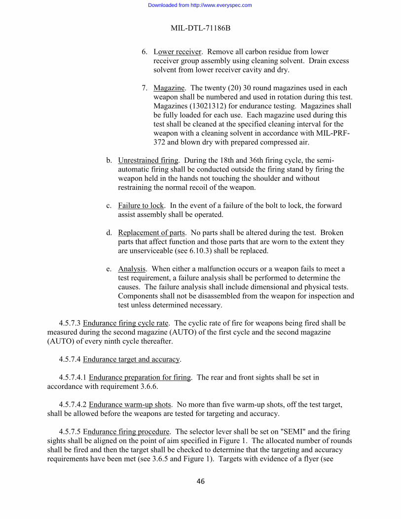
MIL-DTL-71186B
46
6. Lower receiver. Remove all carbon residue from lower receiver group assembly using cleaning solvent. Drain excess solvent from lower receiver cavity and dry.
7. Magazine. The twenty (20) 30 round magazines used in each
weapon shall be numbered and used in rotation during this test. Magazines (13021312) for endurance testing. Magazines shall be fully loaded for each use. Each magazine used during this test shall be cleaned at the specified cleaning interval for the weapon with a cleaning solvent in accordance with MIL-PRF-372 and blown dry with prepared compressed air.
b. Unrestrained firing. During the 18th and 36th firing cycle, the semi-automatic firing shall be conducted outside the firing stand by firing the weapon held in the hands not touching the shoulder and without restraining the normal recoil of the weapon.
c. Failure to lock. In the event of a failure of the bolt to lock, the forward assist assembly shall be operated.
d. Replacement of parts. No parts shall be altered during the test. Broken parts that affect function and those parts that are worn to the extent they are unserviceable (see 6.10.3) shall be replaced.
e. Analysis. When either a malfunction occurs or a weapon fails to meet a test requirement, a failure analysis shall be performed to determine the causes. The failure analysis shall include dimensional and physical tests. Components shall not be disassembled from the weapon for inspection and test unless determined necessary.
4.5.7.3 Endurance firing cycle rate. The cyclic rate of fire for weapons being fired shall be
measured during the second magazine (AUTO) of the first cycle and the second magazine (AUTO) of every ninth cycle thereafter.
4.5.7.4 Endurance target and accuracy.
4.5.7.4.1 Endurance preparation for firing. The rear and front sights shall be set in
accordance with requirement 3.6.6.
4.5.7.4.2 Endurance warm-up shots. No more than five warm-up shots, off the test target, shall be allowed before the weapons are tested for targeting and accuracy.
4.5.7.5 Endurance firing procedure. The selector lever shall be set on "SEMI" and the firing
sights shall be aligned on the point of aim specified in Figure 1. The allocated number of rounds shall be fired and then the target shall be checked to determine that the targeting and accuracy requirements have been met (see 3.6.5 and Figure 1). Targets with evidence of a flyer (see
Downloaded from http://www.everyspec.com

MIL-DTL-71186B
47
6.10.1) or keyholing (see 6.10.2) shall be cause to repeat the test by firing a ten round complement. Failure of any weapon to meet the Target and Accuracy requirements after the repeated test shall be cause for rejection of the inspection lot subject to conducting a failure analysis.
4.5.7.6 Endurance barrel assembly integrity. Upon completion of 2,400 and 6,000 rounds, the barrel assembly shall be magnetic particle inspected in accordance with ASTM E1444 utilizing a current of 400 to 500 amperes for circular continuous magnetization. The barrel assembly shall be examined for evidence of cracks, seams and other injurious defects.
4.5.7.7 Endurance bolt assembly integrity. Upon completion of 2,400 and 6,000 rounds, the
bolt shall be magnetic particle inspected in accordance with ASTM E1444 utilizing standard five turn magnetizing coil with a current of 200 to 300 amperes. Both circular and longitudinal continuous magnetization with wet fluorescent solution shall be used. The bolts shall be examined for evidence of cracks, seams and other injurious defects.
4.5.7.8 Endurance headspace measurement. Headspace for weapons shall be measured at the
beginning of the test and at the completion of the 6000 rounds in accordance with 4.5.3.2. If after the 6000 rounds, the headspace is more than .0028 inches greater than the initial measurement the sample shall be rejected. If after the 6000 rounds, the headspace exceeds 1.4730 inches the sample shall be rejected.
4.5.7.9 Endurance bolt action indent. The bolt shall be retracted to the open rearward
position and held open. A zero indicator reading shall be made on the height of the firing pin indent cylinder before insertion into the plug gage in accordance with Drawing 8440219. The plug gage containing the firing pin indent cylinder shall then be inserted in the barrel chamber. The bolt shall be manually returned to the battery position, the trigger shall be pulled to release the hammer and indent the firing pin indent cylinder. The plug gage shall be removed from the barrel chamber and the depth of the indent on the firing pin indent cylinder computed by measuring the distance from the original zero indicator reading to the bottom of the firing pin impression.
4.5.7.10 Endurance muzzle down position indent. The weapon shall be held in a muzzle
down position with the muzzle end supported. The bolt shall be retracted to the rearward position and held open. A zero indicator reading shall be made on the height of the firing pin indent cylinder before insertion into the plug gage in accordance with Drawing 8840220. The plug gage containing the firing pin indent cylinder shall then be inserted into the barrel chamber. The bolt shall be returned to the battery position under spring action. The trigger shall not be pulled. The plug gage shall be removed from the barrel chamber and the depth of the indent in the firing pin indent cylinder computed by measuring the distance from the original zero indicator reading to the bottom of the firing pin impression. The indent impression shall be visually examined to determine if the concentricity requirement has been met.
4.5.7.11 Endurance firing pin indent location. The firing pin indent position on pressure cylinder shall be measured using approved Standard Measuring & Testing Equipment (SM&TE).
Downloaded from http://www.everyspec.com

MIL-DTL-71186B
48
4.5.7.12 Endurance firing pin protrusion. The firing pin protrusion shall be tested using approved SM&TE with the firing pin in the fired position as specified in accordance with Drawing 13004788.
4.5.8 Interchangeability. The allocated weapons shall be tested for interchangeability by disassembling and then reassembling parts using the parts and the prearranged system provided herein. Interchange of parts shall be accomplished by dividing the parts of each weapon into ten (10) groups of non-mating parts as shown Table IV (as applicable), and distributing the groups into 10 different trays until each tray contains parts for a complete weapon. Groups of parts from the first weapon shall be taken in order and placed in trays one (1) through ten (10) in that sequential order; groups of parts from the second weapon shall be taken in order and placed starting at tray two (2) through tray ten (10) and finishing in tray one (1); groups of parts from the third weapon shall be taken in order and placed starting in tray three (3) through tray ten (10) and finishing in tray two (2); and so on. Commercial parts such as screws, spring pins, etc., shall be placed in the same tray as their mating or associated part. Any commercial part rendered unserviceable by disassembly shall be replaced without penalty to the interchangeability test. The weapons shall be reassembled using only those parts which are in the same tray.
Downloaded from http://www.everyspec.com
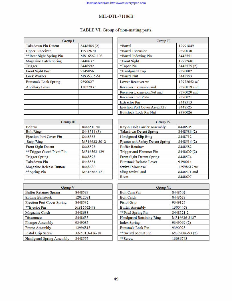
Downloaded from http://www.everyspec.com

Downloaded from http://www.everyspec.com
MIL-DTL-71186B
51
utilizing gage indicator in accordance with Drawing 8440218, plug gage in accordance with Drawing 8440219, plug gage in accordance with Drawing 8440220, and firing pin indent cylinders in accordance with Drawing 13051594 for insertion in the barrel chamber.
4.5.8.2.2 Interchangeability bolt action indent. The bolt shall be retracted to the open
rearward position and held open. A zero indicator reading shall be made on the height of the firing pin indent cylinder before insertion into the plug gage in accordance with Drawing 8440219. The plug gage containing the firing pin indent cylinder shall then be inserted in the barrel chamber. The bolt shall be manually returned to the battery position, the trigger shall be pulled to release the hammer and indent the firing pin indent cylinder. The plug gage shall be removed from the barrel chamber and the depth of the indent on the firing pin indent cylinder computed by measuring the distance from the original zero indicator reading to the bottom of the firing pin impression.
4.5.8.2.3 Interchangeability muzzle down position indent. The weapon shall be held in a
muzzle down position with the muzzle end supported. The bolt shall be retracted to the rearward position and held open. A zero indicator reading shall be made on the height of the firing pin indent cylinder before insertion into the plug gage in accordance with Drawing 8440220. The plug gage containing the firing pin indent cylinder shall then be inserted into the barrel chamber. The bolt shall be returned to the battery position under spring action. The trigger shall not be pulled. The plug gage shall be removed from the barrel chamber and the depth of the indent in the firing pin indent cylinder computed by measuring the distance from the original zero indicator reading to the bottom of the firing pin impression. The indent impression shall be visually examined to determine if the concentricity requirement has been met.
4.5.8.2.4 Interchangeability firing pin indent location. The firing pin indent position on
pressure cylinder shall be measured using approved Standard Measuring & Testing Equipment (SM&TE).
4.5.8.2.5 Interchangeability firing pin protrusion. The firing pin protrusion shall be tested
using approved SM&TE with the firing pin in the fired position as specified in accordance with Drawing 13004788.
4.5.8.3 Interchangeability trigger pull.
4.5.8.3.1 Interchangeability minimum trigger pull.
a. Release the trigger. Place the selector to SEMI. Hold the weapon in the
vertical position. Using trigger pull measuring fixture, 7274758, gradually add 5.5 lbs (2.49 kg) to the center of the trigger and exerted in line parallel to the axis of the barrel bore. To be acceptable, the hammer shall not release.
4.5.8.3.2 Interchangeability maximum trigger pull. a. Release the trigger. Place the selector to SEMI. Hold the weapon in the
vertical position. Using trigger pull measuring fixture, 7274758, gradually
Downloaded from http://www.everyspec.com

MIL-DTL-71186B
52
add 8.5 lbs (3.86 kg) to the center of the trigger and exerted in line parallel to the axis of the barrel bore. To be acceptable, the hammer shall release.
4.5.8.3.3 Interchangeability creep. The weapon shall also be manually tested to assure that
the trigger pull is free of creep (see 3.6.2.3) and that the trigger returns under spring action to its normal forward position after partial or complete trigger pull.
4.5.8.4 Interchangeability function firing.
4.5.8.4.1 Interchangeability function firing semi-automatic. Each weapon shall be fired in accordance with the TM 9-1005-319-10 and shall be held in either the fixture in accordance with Drawing 11837943 or a Government-approved equivalent fixture using ammunition M855A1, 5.56mm ball cartridges in accordance with Drawing 13020533.
4.5.8.4.2 Interchangeability function firing automatic. Each weapon shall be fired in
accordance with the Operator’s Manual 9-1005-319-10 and shall be held in either the stand in accordance with Drawing 11837945 or a Government-approved equivalent stand using ammunition M855A1, 5.56mm ball cartridges in accordance with Drawing 13020533. The selector lever shall be set on "AUTO" for continuous burst firing. The weapon shall be fired using a fully loaded 30 round magazine by pulling the trigger and holding rearward until all 30 rounds from the magazine have been fired.
4.5.8.5 Interchangeability cyclic rate of fire. The cyclic rate of fire measurement shall be
taken during the function firing automatic test (see 4.5.8.4.2), on a minimum of twenty (20) round continuous burst when using a 30 round magazine, while the selector lever is set on "AUTO". The cyclic rate of fire shall be measured using test equipment in accordance with Drawing 8443572.
4.5.8.6 Interchangeability target and accuracy.
4.5.8.6.1 Interchangeability preparation for firing. The rear and front sights shall be set in
accordance with requirement 3.6.6.
4.5.8.6.2 Interchangeability warm-up shots. No more than five warm-up shots, off the test target, shall be allowed before the weapons are tested for targeting and accuracy.
4.5.8.6.3 Interchangeability firing procedure. The selector lever shall be set on "SEMI" and
the firing sights shall be aligned on the point of aim specified in Figure 1. The allocated number of rounds shall be fired and then the target shall be checked to determine that the targeting and accuracy requirements have been met (see 3.6.5 and Figure 1). Targets with evidence of a flyer (see 6.10.1) or keyholing (see 6.10.2) shall be cause to repeat the test by firing a ten round complement. Failure of any weapon to meet the Target and Accuracy requirements after the repeated test shall be cause for rejection of the inspection lot subject to conducting a failure analysis.
Downloaded from http://www.everyspec.com

MIL-DTL-71186B
53
4.5.9 Unique identification (UID). The weapon shall be visually and electronically examined to determine compliance with Drawing 12972652.
4.5.10 Workmanship. Workmanship shall be in accordance with the workmanship
requirements of MIL-W-13855, MIL-W-63150 and visual inspections.
5. PACKAGING
5.1 Packaging. For acquisition purposes, the packaging requirements shall be as specified in the contract or order (see 6.2). When packaging of materiel is to be performed by DoD or in-house contractor personnel, these personnel need to contact the responsible packaging activity to ascertain packaging requirements. Packaging requirements are maintained by the Inventory Control Point’s packaging activities within the Military Service or Defense Agency, or within the military service’s system commands. Packaging data retrieval is available from the managing Military Department’s or Defense Agency’s automated packaging files, CD-ROM products, or by contacting the responsible packaging activity.
6. NOTES
(This section contains information of general or explanatory nature that may be helpful,
but is not mandatory.)
6.1 Intended use. The M4A1 carbine is intended for use by military personnel as a combat weapon.
6.2 Acquisition requirements. Acquisition documents should specify the following:
a. Title, number, and date of this specification. b. Lists of drawings and specifications pertinent to the carbine, showing
applicable revision dates. c. Examination, testing criteria and alternate sample size for components and
weapons. d. Disposition of interchangeability and endurance tested carbines. e. Requirements for submission of first article sample (see 3.1 and 4.2). f. Responsibility for furnishing ammunition. g. Quantity, shipping instructions and test procedures for M4A1 carbines
required for interplant interchangeability test (see 6.9). h. Procedures and method's for demilitarizing and disposing of rejected
material. i. Disposition of Government furnished property. j. Interplant interchangeability.
6.3 Testing firing facilities. Test firing facilities and operating procedures should be
designed by the contractor in conformance with local, state, and Federal regulations and suitable for carrying out prescribed firing tests with safety of operating and visiting personnel.
Downloaded from http://www.everyspec.com

MIL-DTL-71186B
54
6.4 Malfunction types.
a. Failure of bolt to lock. Failure of bolt to fully close and rotate to the locked position in the barrel extension.
b. Failure of the forward assist assembly to assist bolt closure. Failure of the pawl of the forward assist assembly to engage or remain engaged with the bolt carrier serrations during manual attempt to lock the bolt, when the bolt fails to lock on return to the battery position.
c. Doubling. During semi-automatic firing, carbines should be checked to assure that no doubling occurs (i.e., two shots fired with a single trigger pull). Doubling should be recorded as a malfunction.
d. Failure to fire. Failure of the carbine to fire the cartridge, when the cartridge has been fully chambered, bolt has been locked in the battery position, and the trigger has been pulled.
e. Failure to feed from magazine. The bolt strips the round from the magazine (tip of round is outside of magazine), but does not fully exit the magazine. Bolt override or bolt over base.
f. Failure to strip. The bolt fails to strip the round from the magazine (tip of round is not outside of magazine). Often caused by the bolt striking the base of the round, and the tip of the ammunition getting caught on the front wall of the magazine.
g. Failure to eject. Failure of the carbine to eject a round from the carbine, when the cartridge has been fired, and the cartridge case has been completely extracted from the chamber.
h. Failure to chamber. Failure of the carbine to chamber a cartridge that has been completely stripped from the magazine.
i. Failure to extract. Failure of the carbine to remove a cartridge case or unfired cartridge from the chamber.
j. Bolt fails to hold to the rear. Failure of the bolt to remain in the rearward position after the last round in the magazine has been fired.
6.4.1 Defective carbine. A defective carbine is a unit of product which contains one or more
defects (end item assembly or component).
6.5 Submission of contractor inspection equipment designs for approval. Submit copies of designs as required to: Commander, U.S. Army CCDC AC, ATTN: FCDD-ACE-QWC, Picatinny Arsenal, NJ 07806-5000. This address will be specified on the Contract Data Requirements List, DD Form 1423 in the contract.
6.6 Submission of alternative conformance provisions. Alternative conformance procedures,
methods or equipment, such as statistical process control, tool control, other types of sampling procedures, etc. may be used by the contractor when they provide as a minimum the level of quality assurance required by the provisions specified herein. Prior to applying methods or equipment, the contractor should describe them in a written proposal submitted to the government for evaluation (see 6.2). When required, the contractor should demonstrate that the effectiveness of each proposed alternative is equal to or better than the specified quality
Downloaded from http://www.everyspec.com

MIL-DTL-71186B
55
assurance provision(s) herein. In cases of dispute as to whether the contractor's proposed alternative(s) provides equivalent assurance, the provisions of this specification should apply. All approved alternative provisions should be specifically incorporated into the contractor's quality program or detailed inspection system, as applicable.
6.7 Endurance alternate sample size. If five (5) successive inspection lots meet the
requirements, the inspection lot size should be increased to 5,000 M4A1s or a month's production, whichever is smaller, and the inspection sample selected. If rejection of the inspection sample occurs at any time or a First Article is required, the inspection lot size of 1,000 M4A1s (or smaller) should be reinstated and the above procedures repeated in returning to the 5,000 M4A1 (or smaller) lot size.
6.8 Interchangeability alternate sample size. If five successive inspection lots meet the
requirements, the inspection lot size should be increased to 5,000 M4A1s or a month's production, whichever is smaller, and the inspection sample selected. If rejection of the inspection sample occurs at any time, the inspection lot size of 1,000 M4A1s (or smaller) should be reinstated and the above procedures repeated in returning to the 5,000 M4A1 (or smaller) lot size.
6.9 Interplant interchangeability. Each contractor should submit monthly, five M4A1s for
verification, unless otherwise specified. An interplant interchangeability test should be performed using five (5) Government Furnished Equipment (GFE) (see 6.12) weapons representing production from each of the previous manufacturers and five (5) weapons of the contractor's manufacture. This test should be conducted for each set of five (5) GFE weapons. All GFE weapons should be inspected, and the Government should be informed of any non-compliance. The M4A1s subjected to interplant interchangeability test should be given a preliminary hand functioning test in accordance with 4.4 and Table IV to assure proper operation before parts are disassembled from the M4A1. The M4A1s should be tested for headspace, firing pin indent, trigger pull, function firing, cyclic rate of fire, and target and accuracy test specified in methods of inspection 4.5.8.1, 4.5.8.2, 4.5.8.3, 4.5.8.4, 4.5.8.5, and 4.5.8.6 respectively. Inspection, tests and acceptance criteria normally associated with interchange weapons (see 4.5.8) should be performed. Parts should be identified with their manufacturer throughout the test.
6.10 Definitions.
6.10.1 Flyer. A flyer is defined as a shot hole which is a greater distance from the nearest
shot hole than the extreme spread of the other nine holes (including the shot hole nearest the flyer).
6.10.2 Keyholing. Keyholing is defined as any shot hole on the target that is not circular.
6.10.3 Unserviceable part. An unserviceable part is one that causes malfunction of the
carbine or impairs the safety of the user. Parts which are worn, broken, deformed, cracked or contain defects to the extent that they may affect function or safety in operation of the carbine should also be considered unserviceable. If a part exhibits an indication of a crack, seam or other
Downloaded from http://www.everyspec.com

MIL-DTL-71186B
56
injurious defect, the government reserves the right to determine, through a destructive test (i.e. sectioning of the part and polishing), whether or not a crack, seam or other injurious defect is present. If the defect is verified by the destructive test, immediate action should be taken to correct this deficiency.
6.10.4 Binding. To become hindered from free movement due to unexpected contact
between surfaces or parts not designed to do so.
6.10.5 Hammer (fall). Motion of the hammer under spring action from its cocked position to its stop position against the bolt carrier assembly.
6.10.6 Hammer (not fall). The hammer does not move from its cocked position to its stop
position.
6.10.7 Charge. To pull the charging handle to the rear so that hammer becomes locked by the trigger.
6.10.8 Tactile. Perceptible by touch with an increase in force needed to start and remain in
motion
6.10.9 Full trigger pull. The position where the trigger will not depress any further and the hammer has been released.
6.10.10 Partial trigger pull. Trigger position greater than 50% of the way to the point where
the hammer is released.
6.10.11 Battery position. Bolt is forward and locking lugs are locked.
6.11 Recording data.
6.11.1 Target and accuracy sight setting. The following data should be recorded:
(1) Number of weapons tested and number of weapons rejected per shift. (2) Test date. (3) Ammunition lot number. (4) Extreme spread of shot group. (5) Reason for retest (flyer and keyholing). (6) For each weapon that fails, record the following:
(i) Serial number.
(ii) Type of malfunction or failure (see 6.4). (iii) Type of magazine (30 round magazine).
6.11.2 Endurance functioning. The following data should be recorded:
(1) Inspection lot number.
Downloaded from http://www.everyspec.com
MIL-DTL-71186B
57
(2) Weapon serial numbers. (3) Each malfunction and unserviceable part (see 6.4 and 6.10.3).
(i) Weapon round at which it occurred.
(ii) Weapon serial numbers. (iii) Type of firing (automatic or semi-automatic). (iv) Type of malfunction.
(4) Ammunition lot number. (5) Headspace measurement. (6) Each rate of fire measurement with identification of which cycle. (7) Each ammunition defect. (8) The cause of each weapon failure. (9) If applicable, cause of test failure. (10) Type of magazine (30 round magazine).
6.12 Government furnished equipment. The contracting officer should arrange to furnish the
property listed if required:
a. Weapon components used for interplant interchange
6.13 Subject term (key-word) listing. Gun Small arms Weapon Accuracy
6.14 Changes from previous issue. Marginal notations are not used in this revision to
identify changes with respect to the previous issue due to the extent of the changes.
Downloaded from http://www.everyspec.com

MIL-DTL-71186B
58
Custodians: Preparing activity: Army – AR Army – AR Navy – OS (Project 1005-2019-009) Review activities: Navy – AS, CG, MC DLA – CC GSA – FAS
NOTE: The activities listed above were interested in this document as of the date of this document. Since organizations and responsibilities can change, you should verify the currency of the information above using the ASSIST Online database at https://assist.dla.mil.
Downloaded from http://www.everyspec.com