INCH-POUND MIL-STD-2189 (SH) MILITARY STANDARD DESIGN ...
13
MIL-STD-2189 (SH) SECTION 100-1 22 JANUARY 1988 AMSC N/A FSC 1990 DISTRIBUTION STATEMENT A. Approved for public release; distribution is unlimited. INCH-POUND MILITARY STANDARD DESIGN METHODS FOR NAVAL SHIPBOARD SYSTEMS SECTION 100-1 REINFORCEMENT OF OPENINGS IN STRUCTURE OF SURFACE SHIPS OTHER THAN IN PROTECTIVE PLATING Downloaded from http://www.everyspec.com
Transcript of INCH-POUND MIL-STD-2189 (SH) MILITARY STANDARD DESIGN ...
MIL-STD-2189 (SH) SECTION 100-1
22 JANUARY 1988
AMSC N/A FSC 1990
DISTRIBUTION STATEMENT A. Approved for public release; distribution isunlimited.
INCH-POUND
MILITARY STANDARD
DESIGN METHODS FOR NAVAL SHIPBOARD SYSTEMS
SECTION 100-1
REINFORCEMENT OF OPENINGS IN STRUCTURE OF SURFACE SHIPS
OTHER THAN IN PROTECTIVE PLATING
Downloaded from http://www.everyspec.com
MIL-STD-2189(SH)SECTION 100-1
DEPARTMENT OF THE NAVYNAVAL SEA SYSTEMS COMMAND
Washington, DC 20362-51O1
Design Methods for Naval Shipboard SystemsReinforcement of Openings in Structure of Surface Ships, Other Than inProtective Plating
1. This Military Standard is approved for use by the Naval Sea SystemsCommand, Department of the Navy, and is available for use by all Departmentsand Agencies of the Department of Defense.
2. Beneficial comments (recommendations, additions, deletions) and anypertinent data which may be of use in improving this document should beaddressed to: Commander, Naval Sea Systems Command, SEA 5523, Department ofthe Navy, Washington, DC 20362-5101 by using the self-addressed standardi-zation Document Improvement Proposal (DD Form 1426) appearing at the end ofthis document or by letter.
i i
Downloaded from http://www.everyspec.com

MIL-STD-2189(SH)SECTION 100-1
FOREUORD
Purpose The purpose of this standard is to set forth design methods forshipboard components or systems as designated in the title.
Background. The design methods presented in this standard were formerlypresented in a design data sheet (DDS), number 100-1, issued by the U.S. NavalSea Systems Command. It is now being published as a military standard topromote its wider availability throughout the Department of Defense.
i i i
Downloaded from http://www.everyspec.com
Downloaded from http://www.everyspec.com
MIL-STD-2189(SH)SECTION 100-1
1. GENERAL AND SCOPE
1.1 General. The procedures established by MIL-STD-2189(SH) are appli-cable. This section and the basic standard are to be considered as anIntegral single document.
1.2 Scope.for reinforcementopenings are made
(a) To
This standard has been prepared to set forth design methodsaround openings in structural members of naval ships. Suchfor the following purposes:
lighten members.(b) For access or inspection.(c) To allow passage of wiring, piping, and ventilation ducts.
2. REFERENCED DOCUMENTS
Not applicable.
3. DEFINITIONS
Not applicable.
4. GENERAL REQUIREMENTS
4.1 Criteria to establish need for reinforcement. criteria arespecified in 4.1.1 through 4.1.3.
4.1.1 Strength impairment. If the size or location of an openingimpairs the strength of an important structural member, it shall bereinforced. Openings in longitudinal strength structure or main transversebulkheads are considered to be of this nature.
4.1.2 Lightening holes. Lightening holes need not normally bereinforced, but lightening holes in longitudinal, transverses, or stiffenersshall be reinforced if their clear depth is greater than 35 percent of the webdepth, if the length of the hole exceeds its own depth, or if they areunfavorably located.
4.1.3 Size ranges. This standard and the formulas given herein apply toopenings that have a maximum clear dimension, after reinforcement, thatexceeds 5 inches but does not exceed 120 inches. Reinforcements of largeropenings are usually shown on applicable contract drawings, but for webs ofstiffening members (longitudinal, transverses, and stiffeners), Openings of 5inches or less in maximum clear depth shall be reinforced if this dimensionexceeds 40 percent of the web depth of the member.
4.2 Overall requirements, Openings and reinforcement of openings shallconform to the following criteria to minimize their adverse effect onstructural strength.
Downloaded from http://www.everyspec.com
MIL-STD-2189(SH)SECTION 100-1
4.2.1 Openings. Every opening in a stressed area of a structural membercauses stress concentrations. If the opening is large in proportion to thewidth of the member, or too near an edge, stress concentration is increased.if the size or location of an opening is such as to impair the strength of amember below its required factor of safety, measures shall be taken to reducethe stress in way of the hole. This may be done:
(a) By changing the location of the opening. For example, in abeam, holes are best located near the neutral axis.
(b) By changing the shape of the opening.(c) By fitting an insert plate around the opening.(d) By fitting a reinforcing ring around the opening.
The purpose of such reinforcement is to concentrate extra material around theopening and close enough to the plane of the plate that it will deform withthe loaded plate, thus absorbing energy and reducing strains around theopening. The rules in this standard deal with this latter type ofreinforcement.
4.2.2 Reinforcements. Insofar as practicable, holes and reinforcingrings shall conform to the following:
(a) Radii of corners of reinforced openings shall be inaccordance with applicable specifications. Where corner radiiare not specified for square or oblong reinforced openings instructural members, they shall be at least one-eighth of theclear dimension described as follows:
(1) In longitudinal members, normal to the longitudinal axisof the hull.
(2) In transverse members, normal to the neutral axis of themember.
(b) Small openings (maximum dimension less than 10t, where t isthe thickness of the plating) shall be circular.
(c) The reinforcing ring shall be placed symmetrically withrespect to the plate except that for usual reinforcement ofoutside plating there shall be no protrusion of reinforcingring beyond the outboard face of the shell other than thatrequired for the welded joint.
(d) The reinforcing ring shall be of the same material as theplating. For special-treatment steel rings, it is realizedthat forming of the material may cause some change in physicalproperties. The use of tubing (instead of a shaped flat bar)of physical properties equal to or better than those of thereinforced plate is acceptable in such a case.
(e) The welded joint which connects the ring to the plate shallbe 100 percent efficient.
Downloaded from http://www.everyspec.com
MIL-STD-2189(SH)SECTION 100-1
4.3 Formulas for reinforcing-ring sizes.
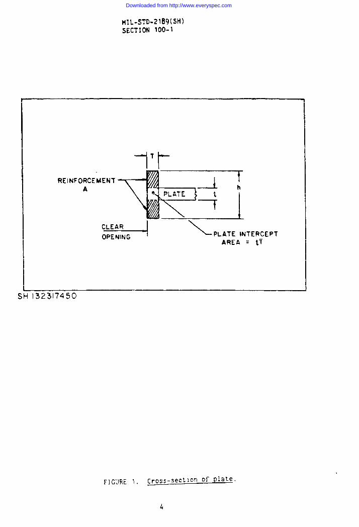
4.3.1. Openings in strength envelope. For openings in the strengthenvelope (that is, in outside plating, uppermost strength deck, inner bottom,and their associated longitudinal framing), for other strength decks withinthe midship three-fifths length, and for strength deck stringer platingforward and aft, where reinforcement is required the following formulas apply(see figure 1).
Minimum cross-sectional area of reinforcing ring = A + tT
Where:
A is the reinforcement (see shaded area of sketch), tT isthe “plate intercept area” (cutback of plate because ofpresence of reinforcing ring).
Values of A for various hole proportions are as follows:
If b is equal to or greater than 2a, A = 30btb + 100
If b is equal to or less than a/2, A = 18btb + 100
For
Where:
t =a =
b =
T =
h =
thickness of plating to be reinforced, in inches.longitudinal dimension, in inches, of clear openingafter reinforcement.
transverse dimension (normal to a), in inches, of clearopening after reinforcement.
thickness of reinforcing bar ring, This shallpreferably be not less than t, and shall be not less than1/4 inch.
depth of ring. This shall not exceed 16T, and shallpreferably be not greater than 8T, particularly in thecase of shell reinforcements. Dimension h shall be notless than t + 1-1/4 inches.
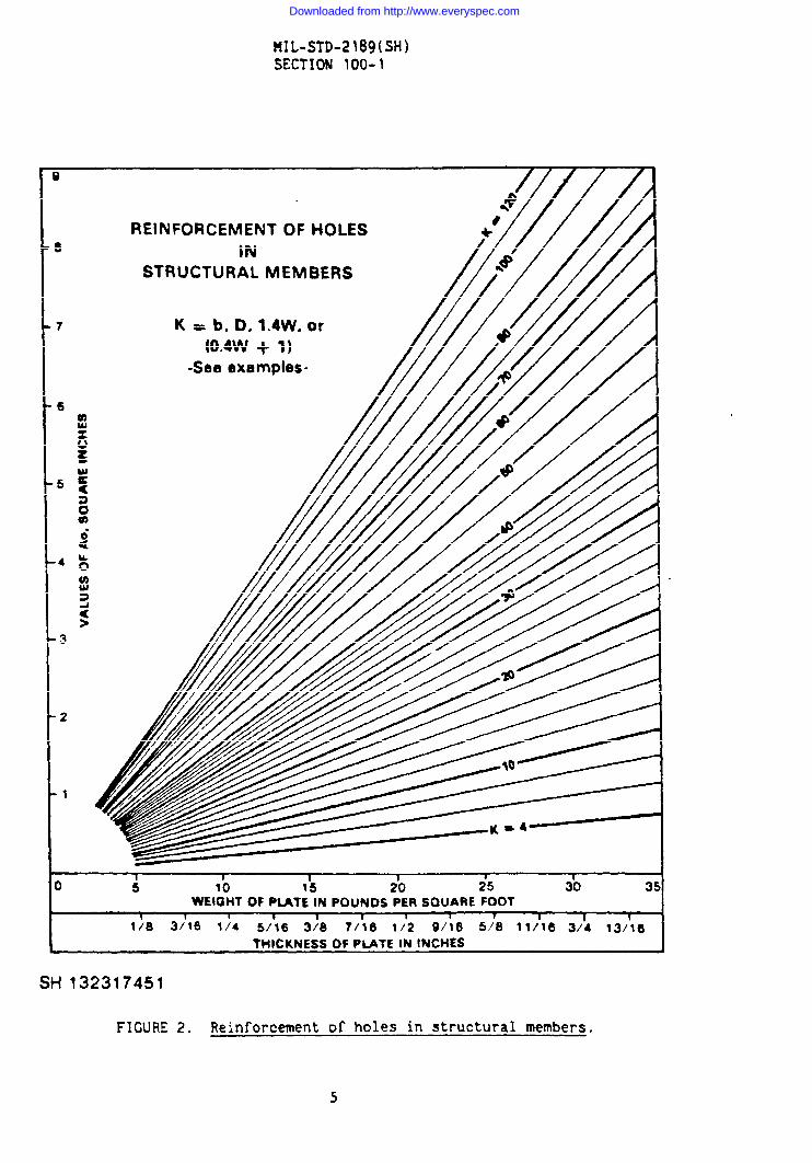
Based on the foregoing requirements, the minimum dimensions of cross-sectionof reinforcing ring, anywhere in the ship, will be (t + 1-1/4) inches by1/4 inch. Values of A may also be derived from the graph shown on figure 2.
Downloaded from http://www.everyspec.com
Downloaded from http://www.everyspec.com
Downloaded from http://www.everyspec.com
MIL-STD-2189(SH)SECTION 100-1
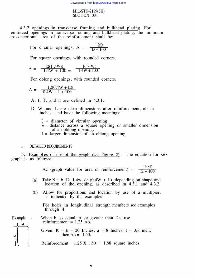
4.3.2 openings in transverse framing and bulkhead plating. Forreinforced openings in transverse framing and bulkhead plating, the minimumcross-sectional area of the reinforcement shall be:
For circular openings, A = 12rDtD + 100
For square openings, with rounded corners,
A = 12(1 .4W)t 16.8 Wt1.4W + 100 = 1.4W + 100
For oblong openings, with rounded corners,
A = 12(0.4W + L)t0.4W + L + 100
A, t, T, and h are defined in 4.3.1.
D, W, and L are clear dimensions after reinforcement, all ininches, and have the following meanings:
D = diameter of circular opening.W = distance across a square opening or smaller dimension
of an oblong opening.L = larger dimension of an oblong opening.
5. DETAILED REQUIREMENTS
5.1 Exampl es of use of the graph (see figure 2). The equation forgraph is as foliows:
Ac (graph value for area of reinforcement) = 24KT’K + 100
Example
(a)
(b)
1:
Take K : b, D, 1.4w, or (0.4W + L), depending on shape andlocation of the opening, as described in 4.3.1 and 4.3.2.
Allow for proportions and location by use of a muitlpier,as indicated by the examples.
For holes in longitudinal strength members see examplesthrough 4
When b iss equal to, or g-eater than, 2a, usereinforcement = 1.25 Ao.
Given: K = b = 20 Inches; a = 8 Inches; t = 3/8 inch;then Ao = 1.50;
Reinforcement = 1.25 X 1.50 = 1.88 square inches.
Downloaded from http://www.everyspec.com
Downloaded from http://www.everyspec.com
MIL-STD-2189(SH)SECTION 100-1
6. NOTES
6.1 Intended use. This standard is for use in specifying reinforcementaround openings in structural members of naval ships.
6.2 Nonapplicability. This standard is not applicable to:
Openings in protective plating.Conventional door openings.Bolted plate and manhole openings.Airport openings.Openings for main sea chests not normal to the shell. Sketchesand calculations (as required) for the proposed method ofreinforcement of these are usually the subject of specialapproval.Holes in webs of stiffening members where the maximum cleardepth of hole exceeds SO percent of the web depth. Where anexcessive hole dimension is required, the web depth should beincreased, or heavier reinforcing should be installed.
6.3 Subject term (key word) listing.
HolesHulls (marine)Strength (mechanics)
-Preparing activity:Navy - SH(Project 1990-N060)
Downloaded from http://www.everyspec.com
Downloaded from http://www.everyspec.com