INCH-POUND MIL-PRF-39012E 27 April 2005 - San-tron
44
MIL-PRF-39012E PERFORMANCE SPECIFICATION FOR RADIO FREQUENCY COAXIAL CONNECTORS Effective Date: July 13, 1995
Transcript of INCH-POUND MIL-PRF-39012E 27 April 2005 - San-tron
MIL-PRF-39012EPERFORMANCE SPECIFICATION FOR RADIO
FREQUENCY COAXIAL CONNECTORS
Effective Date: July 13, 1995
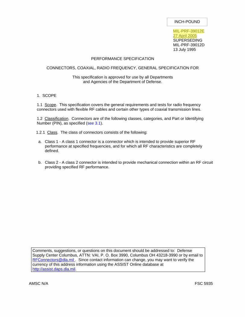
INCH-POUND
MIL-PRF-39012E 27 April 2005 SUPERSEDING MIL-PRF-39012D 13 July 1995
PERFORMANCE SPECIFICATION
CONNECTORS, COAXIAL, RADIO FREQUENCY, GENERAL SPECIFICATION FOR
This specification is approved for use by all Departments and Agencies of the Department of Defense.
1. SCOPE
1.1 Scope. This specification covers the general requirements and tests for radio frequency connectors used with flexible RF cables and certain other types of coaxial transmission lines.
1.2 Classification. Connectors are of the following classes, categories, and Part or Identifying Number (PIN), as specified (see 3.1).
1.2.1 Class. The class of connectors consists of the following:
a. Class 1 - A class 1 connector is a connector which is intended to provide superior RF
performance at specified frequencies, and for which all RF characteristics are completely defined.
b. Class 2 - A class 2 connector is intended to provide mechanical connection within an RF circuit
providing specified RF performance.
Comments, suggestions, or questions on this document should be addressed to: Defense Supply Center Columbus, ATTN: VAI, P. O. Box 3990, Columbus OH 43218-3990 or by email to [email protected] . Since contact information can change, you may want to verify the currency of this address information using the ASSIST Online database at http://assist.daps.dla.mil.
AMSC N/A FSC 5935
Fred
MIL-PRF-39012E
Fred
27 April 2005
MIL-PRF-39012E
2
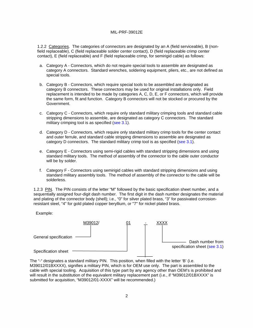
1.2.2 Categories. The categories of connectors are designated by an A (field serviceable), B (non-field replaceable), C (field replaceable solder center contact), D (field replaceable crimp center contact), E (field replaceable) and F (field replaceable crimp, for semirigid cable) as follows:
a. Category A - Connectors, which do not require special tools to assemble are designated as
category A connectors. Standard wrenches, soldering equipment, pliers, etc., are not defined as special tools.
b. Category B - Connectors, which require special tools to be assembled are designated as
category B connectors. These connectors may be used for original installations only. Field replacement is intended to be made by categories A, C, D, E, or F connectors, which will provide the same form, fit and function. Category B connectors will not be stocked or procured by the Government.
c. Category C - Connectors, which require only standard military crimping tools and standard cable
stripping dimensions to assemble, are designated as category C connectors. The standard military crimping tool is as specified (see 3.1).
d. Category D - Connectors, which require only standard military crimp tools for the center contact
and outer ferrule, and standard cable stripping dimensions to assemble are designated as category D connectors. The standard military crimp tool is as specified (see 3.1).
e. Category E - Connectors using semi-rigid cables with standard stripping dimensions and using
standard military tools. The method of assembly of the connector to the cable outer conductor will be by solder.
f. Category F - Connectors using semirigid cables with standard stripping dimensions and using
standard military assembly tools. The method of assembly of the connector to the cable will be solderless.
1.2.3 PIN. The PIN consists of the letter “M” followed by the basic specification sheet number, and a sequentially assigned four-digit dash number. The first digit in the dash number designates the material and plating of the connector body (shell); i.e., “0” for silver plated brass, “3” for passivated corrosion-resistant steel, “4” for gold plated copper beryllium, or "7" for nickel plated brass.
Example:
M39012/ 01 - XXXX
General specification
Dash number from specification sheet (see 3.1)
Specification sheet The “-“ designates a standard military PIN. This position, when filled with the letter ‘B’ (i.e. M39012/01BXXXX), signifies a military PIN, which is for OEM use only. The part is assembled to the cable with special tooling. Acquisition of this type part by any agency other than OEM’s is prohibited and will result in the substitution of the equivalent military replacement part (i.e., if “M39012/01BXXXX” is submitted for acquisition, “M39012/01-XXXX” will be recommended.)

MIL-PRF-39012E
3
2. APPLICABLE DOCUMENTS 2.1 General. The documents listed in this section are specified in sections 3, 4, or 5 of this specification. This section does not include documents cited in other sections of this specification or recommended for additional information or as examples. While every effort has been made to ensure the completeness of this list, document users are cautioned that they must meet all specified requirements cited in sections 3, 4, or 5 of this specification, whether or not they are listed. 2.2 Government documents. 2.2.1 Specifications, standards, and handbooks. The following specifications, standards, and handbooks form a part of this document to the extent specified herein. Unless otherwise specified, the issues of these documents are those cited in the solicitation or contract.
FEDERAL STANDARDS
FED-STD-H28 - Screw-Thread Standards for Federal Services
COMMERCIAL ITEM DESCRIPTIONS
A-A-59588 - Rubber, Silicone
DEPARTMENT OF DEFENSE SPECIFICATIONS
(See ASSIST database for list of specification sheets)
DEPARTMENT OF DEFENSE STANDARDS
MIL-STD-130 - Identification Marking of U.S. Military Property MIL-STD-202 - Test Methods for Electronic and Electrical Component Parts MIL-STD-348 - Radio Frequency Connector Interfaces MIL-STD-889 - Dissimilar Metals
(Copies of these documents are available online at http://assist.daps.dla.mil/quicksearch/ or http://assist.daps.dla.mil. or from the Standardization Documents Order Desk, 700 Robbins Avenue, Building 4D, Philadelphia, PA 19111-5094.) 2.3 Non-Government publications. The following documents form a part of this document to the extent specified herein. Unless otherwise specified, the issues of these documents are those cited in the solicitation or contract.
ASTM INTERNATIONAL
ASTM A342 - Materials, Feebly Magnetic, Permeability of ASTM A484 - Steel, Bars, Billets and Forgings, Stainless ASTM A582 - Free-Machining Stainless and Heat-Resisting Steel Bars ASTM B16 - Rod, Brass, Free-Cutting, Bar and Shapes for use in Screw Machines ASTM B36 - Plate, Brass, Sheet, Strip, and Rolled Bar ASTM B88 - Tube, Water, Seamless Copper ASTM B121 - Plate, Leaded Brass, Sheet, Strip, and Rolled Bar ASTM B124 - Copper and Copper Alloy Forging Rod, Bar, and Shapes ASTM B139 - Rod, Phosphor Bronze, Bar, and Shapes
MIL-PRF-39012E
4
ASTM B152 - Copper Sheet, Strip, Plate, and Rolled Bar ASTM B194 - Copper-Beryllium Alloy Plate, Sheet, Strip and Rolled Bar ASTM B196 - Rod and Bar, Copper-Beryllium Alloy ASTM B197 - Wire, Alloy, Copper-Beryllium ASTM B488 - Gold for Engineering Uses, Electrodeposited Coatings of ASTM B700 - Electrodeposited Coatings of Silver for Engineering Uses ASTM D2116 - Molding and Extrusion Materials, FEP-Fluorocarbon
ASTM D4894 - Polytetrafluoroethylene (PTFE) Grandular Molding and RAM Extrusion Materials ASTM D4895 - Polytetrafluoroethylene (PTFE) Resins Produced From Dispersion
(Copies of these documents are available from http://www.astm.org or ASTM International, P.O. Box C700, 100 Barr Harbor Drive, Conshohocken, PA 19428-2959.)
AMERICAN NATIONAL STANDARDS INSTITUTE, (ANSI)
ANSI B46.1 - Surface Texture (Surface Roughness, Waviness, and Lay) (Copies of these documents are available online from http://www.ansi.org or from the American National Standards Institute, 25 West 43 Street, 4th Floor, New York, NY 10036.)
IEEE Operations Center
IEEE Standard 287 - Precision Coaxial Connectors (Copies of these documents are available online from http://[email protected] or from the IEEE Operations Center, 445 Hoes Lane, Piscataway, New Jersey 08854-1331.)
AEROSPACE INDUSTRIES ASSOCIATION OF AMERICA INC. (AIA/NAS)
NASM20995 - Wire, Safety or Lock (Copies of these documents are available online from http://aia-aerospace.org or from the Aerospace Industries Association of America, 1000 Wilson Boulevard, Suite 1700, Arlington, VA 22209-3901.)
SOCIETY OF AUTOMOTIVE ENGINEERS (SAE)
SAE-AMS-QQ-N-290 - Nickel Plating (Electrodepostied)
SAE-AMS-2700 - Passivation of Corrosion Resistant Steels (Copies of these documents are available online from http://www.sae.org or from the Society of Automotive Engineers, 400 Commonwealth Drive, Warrandale. PA 15096-001.)
ELECTRONIC INDUSTRIES ALLIANCE (EIA)
EIA-364 - Electrical Connector/Socket Test Procedures Including
(Copies of these documents are available online at http://www.eia.org or from the Electronic Industries Alliance, Technology Strategy & Standards Department, 2500 Wilson Boulevard, Arlington, VA 22201.)
MIL-PRF-39012E
5
2.4 Order of precedence. In the event of a conflict between the text of this document and the references cited herein (except for related specification sheets), the text of this document takes precedence. Nothing in this document, however, supersedes applicable laws and regulations unless a specific exemption has been obtained.
3. REQUIREMENTS 3.1 Specification sheets. The individual item requirements shall be as specified herein and in accordance with the applicable specification sheets. In the event of any conflict between requirements of this specification and the specification sheet, the latter shall govern. 3.2 Qualification. Connectors furnished under this specification shall be products that are authorized by the qualifying activity for listing on the applicable qualified products list before contract award (see 4.3 and 6.3).
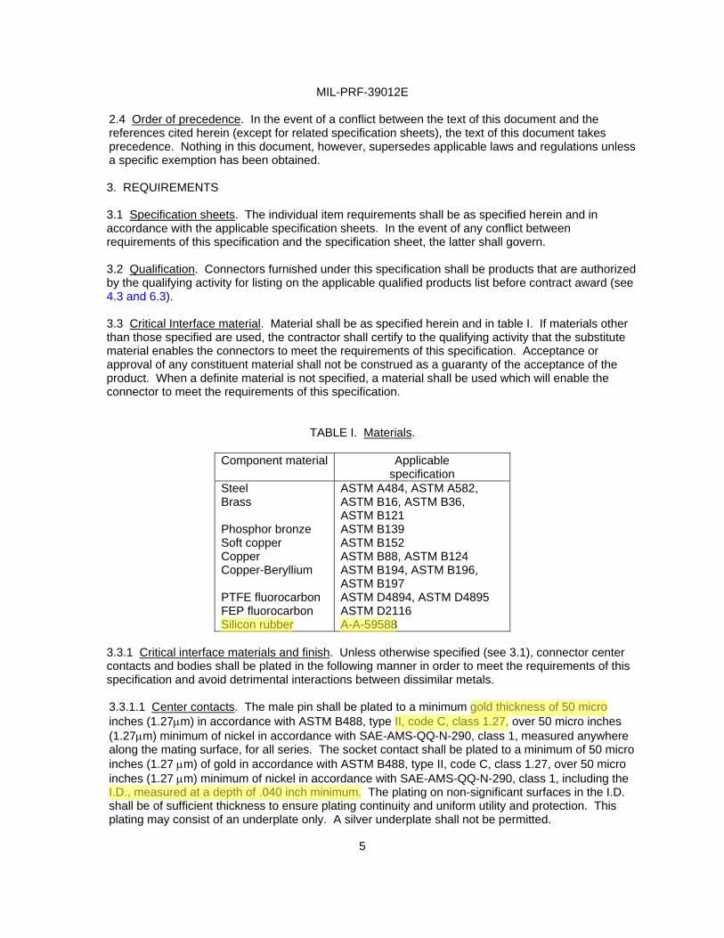
3.3 Critical Interface material. Material shall be as specified herein and in table I. If materials other than those specified are used, the contractor shall certify to the qualifying activity that the substitute material enables the connectors to meet the requirements of this specification. Acceptance or approval of any constituent material shall not be construed as a guaranty of the acceptance of the product. When a definite material is not specified, a material shall be used which will enable the connector to meet the requirements of this specification.
TABLE I. Materials.
Component material Applicable specification
Steel Brass Phosphor bronze Soft copper Copper Copper-Beryllium PTFE fluorocarbon FEP fluorocarbon Silicon rubber
ASTM A484, ASTM A582, ASTM B16, ASTM B36, ASTM B121 ASTM B139 ASTM B152 ASTM B88, ASTM B124 ASTM B194, ASTM B196, ASTM B197 ASTM D4894, ASTM D4895 ASTM D2116 A-A-59588
3.3.1 Critical interface materials and finish. Unless otherwise specified (see 3.1), connector center contacts and bodies shall be plated in the following manner in order to meet the requirements of this specification and avoid detrimental interactions between dissimilar metals. 3.3.1.1 Center contacts. The male pin shall be plated to a minimum gold thickness of 50 micro inches (1.27µm) in accordance with ASTM B488, type II, code C, class 1.27, over 50 micro inches (1.27µm) minimum of nickel in accordance with SAE-AMS-QQ-N-290, class 1, measured anywhere along the mating surface, for all series. The socket contact shall be plated to a minimum of 50 micro inches (1.27 µm) of gold in accordance with ASTM B488, type II, code C, class 1.27, over 50 micro inches (1.27 µm) minimum of nickel in accordance with SAE-AMS-QQ-N-290, class 1, including the I.D., measured at a depth of .040 inch minimum. The plating on non-significant surfaces in the I.D. shall be of sufficient thickness to ensure plating continuity and uniform utility and protection. This plating may consist of an underplate only. A silver underplate shall not be permitted.
Fred
gold thickness of 50 micro
Fred
II, code C, class 1.27,
Fred
I.D., measured at a depth of .040 inch minimum.
fred
Silicon rubber
fred
A-A-59588
MIL-PRF-39012E
6
NOTE: No PIN changes will be made as a result of this plating change. The change will be tracked via the manufacturer’s date code.
3.3.1.2 Connector bodies. All brass bodied connectors shall be silver plated in accordance with ASTM-B700 to a minimum thickness of 0.0002 inch (0.005 mm) over a copper underplate or shall be nickel plated in accordance with SAE-AMS-QQ-N-290 over a copper underplate, only when specified on the individual specification sheet. If not specifically noted the plating shall be silver. (Note of caution! Nickel plated connectors may cause Passive Intermodulation (PIM) problems. The user is ADVISED to check the application involved when choosing this type of plating.) All copper beryllium bodied connectors shall be gold plated to a minimum thickness of 50 micro inches (1.27µm) in accordance with ASTM B488, type II, code C, class 1.27, over a copper flash. All corrosion resistant steel bodied connectors shall be passivated in accordance with SAE-AMS-2700, unless otherwise specified (see 3.1). NOTE: Ferrous or nickel alloys shall not be used on brass or copper beryllium bodied connectors (i.e. coupling nuts, etc.). (Past experience has shown that these plating conditions allow these connectors to meet the performance requirements of this specification.) 3.3.2 Dissimilar metals. Dissimilar metals between which an electromotive couple may exist shall not be placed in contact with each other. Reference is made to MIL-STD-889 for definition of dissimilar metals. 3.3.3 Nonmagnetic materials. All parts (except hermetic sealed connectors) shall be made from materials which are classed as nonmagnetic (see 3.8).
3.3.4 Spring members. Unless otherwise specified (see 3.1), center contact spring members shall be made of copper beryllium. 3.3.5 Recycled, recovered, or environmentally preferable materials. Recycled, recovered, or environmentally preferable materials should be used to the maximum extent possible, provided that the material meets or exceeds the operational and maintenance requirements, and promotes economically advantageous life cycle costs.
3.4 Configuration and features. Connectors shall be of the configuration and physical dimensions specified (see 3.1). On class I connectors (see 1.2.1) each half of a connector pair must be separately optimized in VSWR (see 4.6.11). It is not permitted to compensate for discontinuities of one connector by the design of the mating connector. 3.4.1 Mating (visual indication). When applicable (see 3.1), a visual means shall be provided to indicate when two mating connectors are properly mated. 3.4.2 Screw threads. Screw threads shall be in accordance with FED-STD-H28 unless otherwise specified (see 3.1).
3.4.3 Connector interfaces. Connector interfaces shall be in accordance with MIL-STD-348 unless otherwise specified (see 3.1).
3.5 Force to engage/disengage. 3.5.1 Bayonet and threaded types. When tested as specified in 4.6.2.1, the torque necessary to completely couple or uncouple the connectors shall not exceed that specified (see 3.1). Also the longitudinal force necessary to initiate the engaging or disengaging cycle shall not except that specified (see 3.1).
Fred
brass bodied connectors shall be silver plated
Fred
inch
Fred
0.0002
Fred
or
Fred
only when
Fred
All copper beryllium
Fred
bodied connectors shall be gold plated to a minimum thickness of 50
Fred
center contact spring members shall
Fred
be made of copper beryllium.
MIL-PRF-39012E
7
3.5.2 “Push on” connector types. When tested as specified in 4.6.2.2, the forces necessary to fully engage or disengage the connector shall not exceed that specified (see 3.1). 3.6 Coupling proof torque. When tested as specified in 4.6.3, the coupling mechanism (threaded types) shall not be dislodged, and the connector shall meet requirements of 3.5.1. The interface dimensions of the connector shall remain as specified (see 3.1). 3.7 Mating characteristics. When connectors are tested as specified in 4.6.4, the mating dimensions shall be gauged as specified and the dimensions shall remain within the specified tolerances (see 3.1).
3.8 Permeability of nonmagnetic materials. When connectors (except hermetic sealed) are tested as specified in 4.6.5, the permeability (Mu) shall be less than 2.0. The permeability does not apply to connector hardware.
3.9 Hermetic seal (pressurized connectors). When connectors are tested as specified in 4.6.6, the leakage rate shall not exceed that specified (see 3.1). 3.10 Leakage (pressurized connectors). When connectors are tested as specified in 4.6.7, there shall be no leakage as detected by escaping air bubbles. 3.11 Insulation resistance. When connectors are tested as specified in 4.6.8, the insulation resistance shall not be less than that specified (see 3.1).
3.12 Center contact retention. When all class I connectors, and class II where applicable (see 3.1) are tested as specified in 4.6.9, the center contacts must not be displaced from the specified interface dimensions in the uncabled connector by the application of the specified axial force (see 3.1) in either direction or torque.
3.13 Corrosion. When connectors are tested as specified in 4.6.10, there shall be no exposure of the base metal on the interface or mating surface, and they shall meet the requirements of 3.5.1 or 3.5.2 as applicable.
3.14 Voltage standing wave ratio (VSWR). When connectors are tested as specified in 4.6.11, the VSWR shall not exceed that specified over the frequency range specified (see 3.1).
3.15 Connector durability. When connectors are tested as specified in 4.6.12, they shall show no evidence of severe mechanical damage and the coupling device shall remain functional. Connectors shall meet the applicable requirements of 3.5 and 3.7.
3.16 Contact resistance. When connectors are tested as specified in 4.6.13, the contact resistance of the center contact, outer contact, and braid to connector shall be as specified (see 3.1). The following statement takes precedence over any specification sheet interpretation. The outer contact resistance values given for steel bodied connectors are typical values and are for engineering information purposes only.
3.17 Dielectric withstanding voltage. When connectors are tested as specified in 4.6.14, there shall be no evidence of breakdown.
Fred
center contacts must not be displaced from the specified interface
Fred
dimensions
Fred
uncabled
MIL-PRF-39012E
8
3.18 Vibration. When the cabled (or wired, as applicable) connector is tested as specified in 4.6.15, there shall be no electrical interruptions exceeding 1 microsecond (µs), or as otherwise specified (see 3.1). There shall be no evidence of visual mechanical damage after the test, and the contact resistance of the center contact shall not be changed by more than the specified amount (see 3.1 and 3.16). 3.19 Shock (specified pulse). When the cabled (or wired, as applicable) connector is tested as specified in 4.6.16, there shall be no electrical interruptions exceeding 1 µs unless otherwise specified (see 3.1). There shall be no evidence of visual or mechanical damage after the test, and the contact resistance of the center contact shall not be changed by more than the specified amount (see 3.1).
3.20 Thermal shock. After testing as specified in 4.6.17, there shall be no evidence of visual mechanical damage to the connector and it shall meet the dielectric withstanding voltage requirement (see 3.17), and the contact resistance specified for the center contact shall not be exceeded (see 3.16).
3.21 Moisture resistance. When connectors are tested as specified in 4.6.18, there shall be no evidence of damage. They shall withstand the dielectric withstanding voltage specified (see 3.17), and the insulation resistance shall not be less than that specified (see 3.11). 3.22 Corona level. When connectors are tested as specified in 4.6.19, at the altitude and voltage specified (see 3.1), there shall be no evidence of sustained corona discharge.
3.23 RF high potential withstanding voltage. When connectors are tested as specified in 4.6.20, there shall be no breakdown, or the leakage current specified shall not be exceeded (see 3.1).
3.24 Cable retention force. When connectors are tested as specified in 4.6.21, there shall be no evidence of mechanical failure, loosening, rupture, or discontinuity. The direct clamping of the cable jacket shall not be the primary method of cable retention.
3.25 Coupling mechanism retention force. When tested as specified in 4.6.22, the coupling mechanism shall not be dislodged from the connector and shall be capable of meeting the requirements of 3.5.1 immediately after the test.
3.26 RF leakage. When connectors are tested as specified in 4.6.23, the total leakage, cable to cable shall not exceed that specified (see 3.1).
3.27 RF insertion loss. When connectors are tested as specified in 4.6.24, the insertion loss shall not exceed that specified (see 3.1).
3.28 Assembly instructions. Complete assembly instructions shall be furnished by the vendor with each connector procured under this specification. It is not the intention of this specification to require assembly instructions with uncabled connectors (i.e., solder pot, solder tab or posts, etc.). Assembly instructions shall include:
a. Cable preparation – stripping dimensions and tolerances. b. List and description of crimping or special tools if required (see 1.2.2). c. Pictorial presentation of sub-assemblies and loose piece parts d. Sufficient pertinent dimensions for verification of correct parts; as a minimum the cable entry openings for conductor, dielectric, braid, and jacket shall be specified. e. Recommended cable clamp tightening torque (if applicable). f. Military PIN and manufacturer’s PIN.
MIL-PRF-39012E
9
3.29 Marking. Connectors and associated fittings shall be permanently and legibly marked in accordance with the general marking requirements of ML-STD-130 with the military PIN (see 1.2.3), manufacturer’s federal supply code, and final assembly date code. The marking location is optional; when practicable, a location should be picked that will be least likely to be covered in cable assembly or installation. Marking is required on all parts manufactured to this specification unless specifically excepted (see 3.1). 3.30 Workmanship. Connectors and associated fittings shall be processed in such a manner as to be uniform in quality and shall be free from sharp edges, burrs and other defects that will affect life, serviceability or appearance. 3.31 Manufacturers’ control drawing. Connector manufacturers shall insure that special tooling and dies are documented. The replacement category A, C, D, E, or F PIN’s shall be listed on the manufacturers’ control drawing.
3.32 Safety wire hole pullout. When applicable (see 3.1), the connectors are to be tested as specified in 4.6.25. There shall be no evidence of hole tear out.
4. VERIFICATION
4.1 Classification of inspections. The inspection requirements specified herein are classified as follows:
a. Qualification inspection (see 4.3) b. Conformance inspection (see 4.4).
c. Periodic inspection (see 4.5).
4.2 Inspection conditions. Unless otherwise specified, all inspections shall be performed in accordance with the test conditions specified in the “GENERAL REQUIREMENTS” of MIL-STD-202 or EIA-364. For each test of threaded coupling connectors, where the test is performed on mated pairs, the pair shall be torqued to the specified value (see 3.1). 4.3 Qualification inspection. Qualification inspection shall be performed at a laboratory acceptable to the Government (see 6.3) on sample units produced with equipment and procedures normally used in production.
4.3.1 Sample size. Thirty class 1 connectors of the same PIN, or eighteen class 2 connectors of the same PIN with its mating connector (see 1.2.1), shall be subjected to qualification inspection. 4.3.2 Group qualification. For group qualification of all series of connectors covered by this specification (see 3.1). Group qualification will be limited to those connectors for which evidence of manufacturing capability is demonstrated by providing engineering drawings to the qualifying agency. The Government reserves the right to authorize performance of any or all qualification inspection of additional types in the group that are considered necessary for qualification within each group.
4.3.3 Inspection routine. The sample shall be subjected to the inspections specified in table II. All sample units shall be subjected to the inspection of group I. The sample units shall then be divided equally into six groups of 5 units (class 1) or three units each (class 2) and subjected to the inspection for their particular group and in the sequence given for that group.
MIL-PRF-39012E
10
4.3.4 Failures. One or more failures shall be cause for refusal to grant qualification approval.
4.3.5 Retention of qualification. To retain qualification, the contractor shall verify in coordination with the qualifying activity the capability of manufacturing products which meet the performance requirements of this specification. Refer to the qualifying activity for the guidelines necessary to retain qualification to this particular specification. The contractor shall immediately notify the qualifying activity at any time that the inspection data indicates failure of the qualified product to meet the performance requirements of this specification.
MIL-PRF-39012E
11
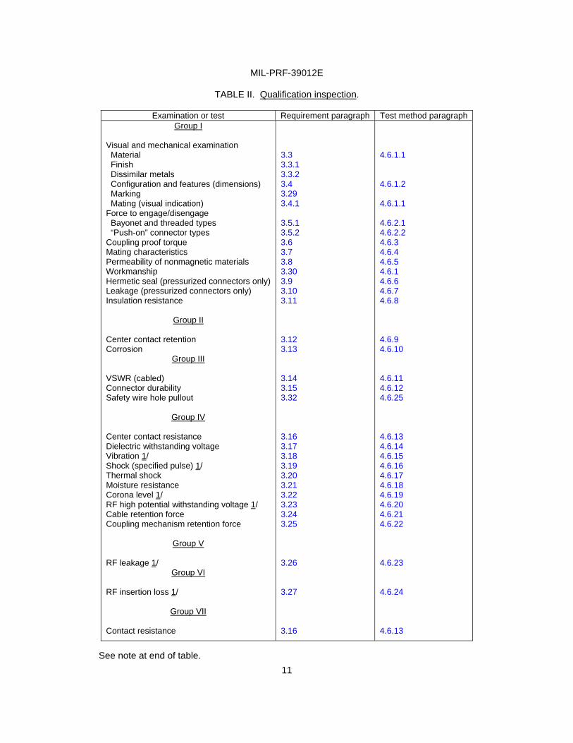
TABLE II. Qualification inspection.
See note at end of table.
Examination or test Requirement paragraph Test method paragraph Group I
Visual and mechanical examination Material Finish Dissimilar metals Configuration and features (dimensions) Marking Mating (visual indication) Force to engage/disengage Bayonet and threaded types “Push-on” connector types Coupling proof torque Mating characteristics Permeability of nonmagnetic materials Workmanship Hermetic seal (pressurized connectors only) Leakage (pressurized connectors only) Insulation resistance
Group II
Center contact retention Corrosion
Group III
VSWR (cabled) Connector durability Safety wire hole pullout
Group IV
Center contact resistance Dielectric withstanding voltage Vibration 1/ Shock (specified pulse) 1/ Thermal shock Moisture resistance Corona level 1/ RF high potential withstanding voltage 1/ Cable retention force Coupling mechanism retention force
Group V
RF leakage 1/ Group VI
RF insertion loss 1/
Group VII
Contact resistance
3.3 3.3.1 3.3.2 3.4 3.29 3.4.1 3.5.1 3.5.2 3.6 3.7 3.8 3.30 3.9 3.10 3.11 3.12 3.13 3.14 3.15 3.32 3.16 3.17 3.18 3.19 3.20 3.21 3.22 3.23 3.24 3.25 3.26 3.27 3.16
4.6.1.1 4.6.1.2 4.6.1.1 4.6.2.1 4.6.2.2 4.6.3 4.6.4 4.6.5 4.6.1 4.6.6 4.6.7 4.6.8 4.6.9 4.6.10 4.6.11 4.6.12 4.6.25 4.6.13 4.6.14 4.6.15 4.6.16 4.6.17 4.6.18 4.6.19 4.6.20 4.6.21 4.6.22 4.6.23 4.6.24 4.6.13
MIL-PRF-39012E
12
TABLE II. Qualification inspection – Continued.
1/ These tests to be performed only during initial qualification as long as the qualifying design and manufacturing process has not been changed.
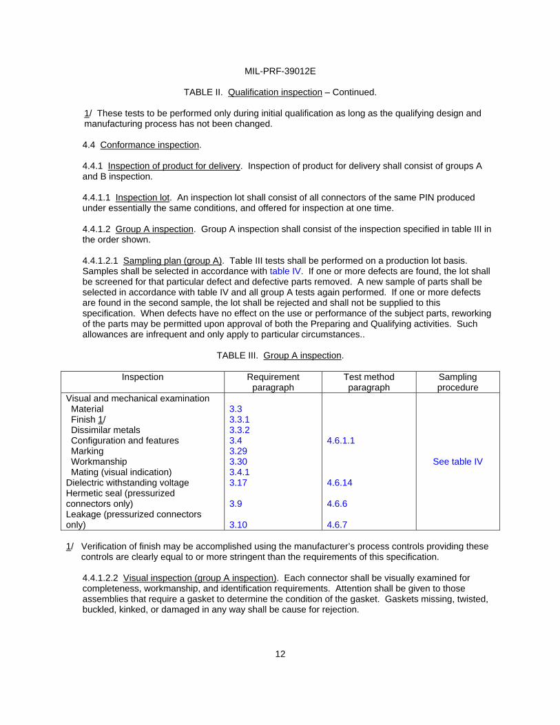
4.4 Conformance inspection. 4.4.1 Inspection of product for delivery. Inspection of product for delivery shall consist of groups A and B inspection. 4.4.1.1 Inspection lot. An inspection lot shall consist of all connectors of the same PIN produced under essentially the same conditions, and offered for inspection at one time. 4.4.1.2 Group A inspection. Group A inspection shall consist of the inspection specified in table III in the order shown.
4.4.1.2.1 Sampling plan (group A). Table III tests shall be performed on a production lot basis. Samples shall be selected in accordance with table IV. If one or more defects are found, the lot shall be screened for that particular defect and defective parts removed. A new sample of parts shall be selected in accordance with table IV and all group A tests again performed. If one or more defects are found in the second sample, the lot shall be rejected and shall not be supplied to this specification. When defects have no effect on the use or performance of the subject parts, reworking of the parts may be permitted upon approval of both the Preparing and Qualifying activities. Such allowances are infrequent and only apply to particular circumstances..
TABLE III. Group A inspection.
Inspection Requirement
paragraph Test method paragraph
Sampling procedure
Visual and mechanical examination Material Finish 1/ Dissimilar metals Configuration and features Marking Workmanship Mating (visual indication) Dielectric withstanding voltage Hermetic seal (pressurized connectors only) Leakage (pressurized connectors only)
3.3 3.3.1 3.3.2 3.4 3.29 3.30 3.4.1 3.17 3.9 3.10
4.6.1.1 4.6.14 4.6.6 4.6.7
See table IV
1/ Verification of finish may be accomplished using the manufacturer’s process controls providing these controls are clearly equal to or more stringent than the requirements of this specification.
4.4.1.2.2 Visual inspection (group A inspection). Each connector shall be visually examined for completeness, workmanship, and identification requirements. Attention shall be given to those assemblies that require a gasket to determine the condition of the gasket. Gaskets missing, twisted, buckled, kinked, or damaged in any way shall be cause for rejection.
MIL-PRF-39012E
13
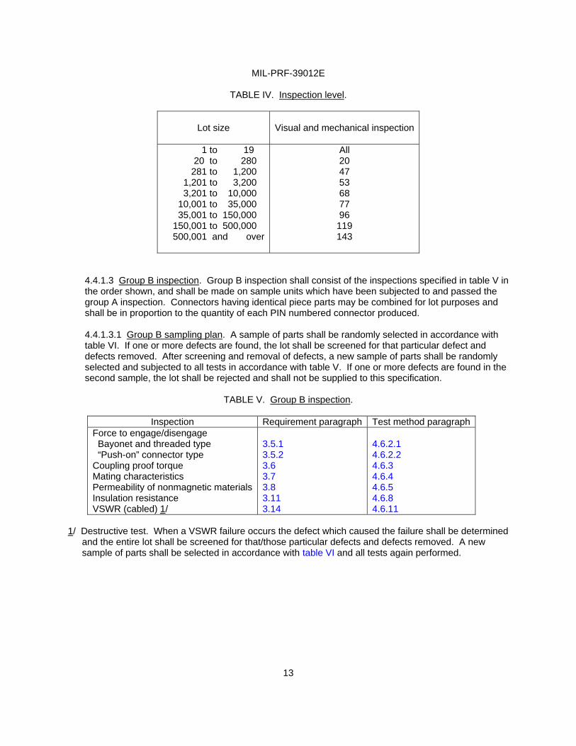
TABLE IV. Inspection level.
Lot size
Visual and mechanical inspection
1 to 19 20 to 280
281 to 1,200 1,201 to 3,200 3,201 to 10,000 10,001 to 35,000 35,001 to 150,000 150,001 to 500,000
500,001 and over
All 20 47 53 68 77 96 119 143
4.4.1.3 Group B inspection. Group B inspection shall consist of the inspections specified in table V in the order shown, and shall be made on sample units which have been subjected to and passed the group A inspection. Connectors having identical piece parts may be combined for lot purposes and shall be in proportion to the quantity of each PIN numbered connector produced. 4.4.1.3.1 Group B sampling plan. A sample of parts shall be randomly selected in accordance with table VI. If one or more defects are found, the lot shall be screened for that particular defect and defects removed. After screening and removal of defects, a new sample of parts shall be randomly selected and subjected to all tests in accordance with table V. If one or more defects are found in the second sample, the lot shall be rejected and shall not be supplied to this specification.
TABLE V. Group B inspection.
Inspection Requirement paragraph Test method paragraph
Force to engage/disengage Bayonet and threaded type “Push-on” connector type Coupling proof torque Mating characteristics Permeability of nonmagnetic materialsInsulation resistance VSWR (cabled) 1/
3.5.1 3.5.2 3.6 3.7 3.8 3.11 3.14
4.6.2.1 4.6.2.2 4.6.3 4.6.4 4.6.5 4.6.8 4.6.11
1/ Destructive test. When a VSWR failure occurs the defect which caused the failure shall be determined
and the entire lot shall be screened for that/those particular defects and defects removed. A new sample of parts shall be selected in accordance with table VI and all tests again performed.
MIL-PRF-39012E
14
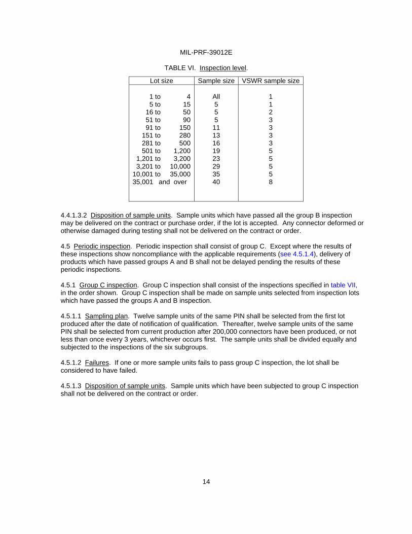
TABLE VI. Inspection level.
4.4.1.3.2 Disposition of sample units. Sample units which have passed all the group B inspection may be delivered on the contract or purchase order, if the lot is accepted. Any connector deformed or otherwise damaged during testing shall not be delivered on the contract or order. 4.5 Periodic inspection. Periodic inspection shall consist of group C. Except where the results of these inspections show noncompliance with the applicable requirements (see 4.5.1.4), delivery of products which have passed groups A and B shall not be delayed pending the results of these periodic inspections. 4.5.1 Group C inspection. Group C inspection shall consist of the inspections specified in table VII, in the order shown. Group C inspection shall be made on sample units selected from inspection lots which have passed the groups A and B inspection. 4.5.1.1 Sampling plan. Twelve sample units of the same PIN shall be selected from the first lot produced after the date of notification of qualification. Thereafter, twelve sample units of the same PIN shall be selected from current production after 200,000 connectors have been produced, or not less than once every 3 years, whichever occurs first. The sample units shall be divided equally and subjected to the inspections of the six subgroups. 4.5.1.2 Failures. If one or more sample units fails to pass group C inspection, the lot shall be considered to have failed. 4.5.1.3 Disposition of sample units. Sample units which have been subjected to group C inspection shall not be delivered on the contract or order.
Lot size Sample size VSWR sample size
1 to 45 to 15
16 to 5051 to 9091 to 150
151 to 280281 to 500501 to 1,200
1,201 to 3,2003,201 to 10,000
10,001 to 35,00035,001 and over
All 5 5 5 11 13 16 19 23 29 35 40
1 1 2 3 3 3 3 5 5 5 5 8
MIL-PRF-39012E
15
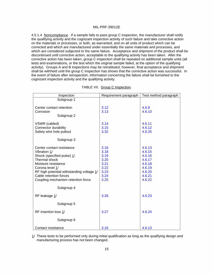
4.5.1.4 Noncompliance. If a sample fails to pass group C inspection, the manufacturer shall notify the qualifying activity and the cognizant inspection activity of such failure and take corrective action on the materials or processes, or both, as warranted, and on all units of product which can be corrected and which are manufactured under essentially the same materials and processes, and which are considered subjected to the same failure. Acceptance and shipment of the product shall be discontinued until corrective action, acceptable to the qualifying activity has been taken. After the corrective action has been taken, group C inspection shall be repeated on additional sample units (all tests and examinations, or the test which the original sample failed, at the option of the qualifying activity). Groups A and B inspections may be reinstituted, however, final acceptance and shipment shall be withheld until the group C inspection has shown that the corrective action was successful. In the event of failure after reinspection, information concerning the failure shall be furnished to the cognizant inspection activity and the qualifying activity.
TABLE VII. Group C inspection.
Inspection Requirement paragraph Test method paragraph
Subgroup 1
Center contact retention Corrosion
Subgroup 2
VSWR (cabled) Connector durability Safety wire hole pullout
Subgroup 3
Center contact resistance Vibration 1/ Shock (specified pulse) 1/ Thermal shock Moisture resistance Corona level 1/ RF high potential withstanding voltage 1/Cable retention forces Coupling mechanism retention force
Subgroup 4
RF leakage 1/
Subgroup 5
RF insertion loss 1/
Subgroup 6
Contact resistance
3.12 3.13 3.14 3.15 3.32 3.16 3.18 3.19 3.20 3.21 3.22 3.23 3.24 3.25 3.26 3.27 3.16
4.6.9 4.6.10 4.6.11 4.6.12 4.6.25 4.6.13 4.6.15 4.6.16 4.6.17 4.6.18 4.6.19 4.6.20 4.6.21 4.6.22 4.6.23 4.6.24 4.6.13
1/ These tests to be performed only during initial qualification as long as the qualifying design and manufacturing process has not been changed.
MIL-PRF-39012E
16
4.6 Methods of inspection. 4.6.1 Test methods. The following identified tests and test methods assure connector integrity within typical operating conditions and applications. Alternate commercial industry standard test methods are allowed; however when an alternate method is used, the qualifying activity must be notified prior to the performance of the test. The test method described herein are proven methods and shall be the referee methods in case of dispute. 4.6.1.1 Visual and mechanical examination. Connectors and associated fittings shall be examined to verify that the design, construction, physical dimensions, assembly instructions, marking and workmanship are in accordance with the applicable requirements (see 3.1, 3.3, 3.4, 3.28, 3.29, and 3.30). 4.6.1.2 Dimensional examination. Mating dimensions shall be examined by mating the connector with its applicable mating gauges or other suitable means acceptable to the Government.
NOTE: The associated individual specification sheets show the overall dimension of the connector when assembled to the appropriate cable. Mating interface dimension are to be found in MIL-STD-348. The cable end construction and other dimensions are controlled by performance requirements of the specification (i.e., cable retention, VSWR, RF leakage, etc., with cable in place).
4.6.2 Force to engage/disengage. 4.6.2.1 Bayonet and threaded types (see 3.5.1). The connector shall be engaged with its mating standard part (see 3.1). During the entire coupling/uncoupling cycle (until the connector is fully engaged/disengaged) the forces and/or torques necessary shall not exceed those specified (see 3.1). A threaded coupled connector is fully engaged with its mating standard part when their reference planes (see MIL-STD-348) coincide. A bayonet coupled connector is fully engaged with its mating standard part when the bayonet studs have passed the detent and their reference planes coincide. No additional tightening torque shall be applied. The mating standard part is a steel jig containing the critical interface dimensions finished to the tolerances specified (see MIL-STD-348). Its spring members when applicable shall be heat treated beryllium copper. The surface finish or mating surfaces shall be 16 microinches, maximum in accordance with ANSI B46.1. 4.6.2.2 “Push-on” connector types (see 3.5.2). The connector under test shall be engaged with its standard mating part (gauge). During this engaging cycle the force necessary to fully engage the connectors shall not exceed that specified (see 3.1). Upon completion of engagement, an opposite force necessary for disengagement shall be applied. This force shall be within the limits specified, and shall include any unlatching forces required.
4.6.3 Coupling proof torque (see 3.6). The connector under test shall be engaged with its mating standard part (gauge) and the coupling nut tightened to the torque value specified (see 3.1). After one minute the connector under test and its mating standard part shall be disengaged. 4.6.4 Mating characteristics (see 3.7). After insertion of the specified oversize pin the specified number of times (see 3.1), the contact to be tested shall be held rigid by means of a suitable jig or fixture. A gauge containing the test pin or test ring and a suitable force indicating dial shall be aligned to within 0.004 TIR of any plane passing through the axis of the contact under test. Engagement or withdrawal of the test pin or test ring shall be made smoothly and at such a rate that the dial does not bounce or otherwise give a false reading. The test pin or test ring may be chamfered to facilitate entry, but the specified engagement length shall not include the chamfer length and the finish shall be as specified and in accordance with ANSI B46.1.
MIL-PRF-39012E
17
4.6.5 Permeability of nonmagnetic materials (see 3.8). The permeability of the connector shall be measured with an indicator conforming to ASTM A342.
4.6.6 Hermetic seal (see 3.9). Connectors shall be tested in accordance with method 112, MIL-STD-202. The following details shall apply:
a. Test condition letter: C b. Procedure number: I.
c. Leakage rate sensitivity: 10-8 cubic centimeters per second.
4.6.7 Leakage (pressurized) (see 3.10). Connectors shall be subjected to air pressure specified (see 3.1) applied to one end, and the whole assembly immersed in water at a temperature of 15º to 25ºC. The connector shall remain immersed for at least 2 minutes. 4.6.8 Insulation resistance (see 3.11). Connectors without cables (when applicable) shall be tested in accordance with method 302, test condition B, MIL-STD-202. Measure between the center contact and body.
4.6.9 Center contact retention (see 3.12). An axial force (see 3.1) shall be applied, first in one direction and then the other, to the center contact of an assembled and uncabled connector utilizing a method and force measuring device suitable to the Government. The inner contact shall be inspected after the force has been applied in one direction and again after the force has been applied in the opposite direction to determine if the contact has been displaced from the specified interface dimensions. Torque: The torque specified shall be applied to the center contact of an unmated connector for a minimum period of 10 seconds, as applicable (see 3.1).
4.6.10 Corrosion (see 3.13). Unmated and uncabled connectors shall be tested in accordance with method 101, MIL-STD-202. The following details and exceptions shall apply:
a. Test condition letter: See 3.1. b. Salt solution: 5 percent.
After exposure, connectors shall be washed, shaken and lightly brushed as specified in method 101 of MIL-STD-202 and then permitted to dry for 24 hours at 40ºC. Connectors shall then be examined for evidence of corrosion, pitting, and ease of coupling.
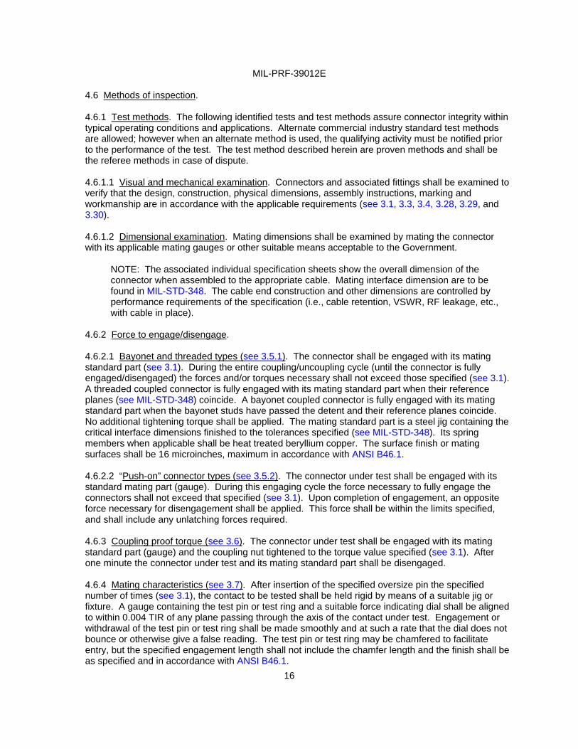
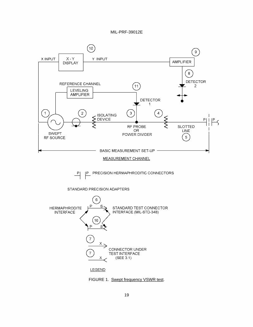
4.6.11 VSWR (see 3.14). The VSWR shall be measured in accordance with the following procedure or a method acceptable to the Government. In the event of dispute the method outlined herein shall be used. Diagrams for the swept frequency VSWR system to check out the measurement procedures are shown on figure 1.
In the basic measurement setup on figure 1, detector 1 provides a feedback signal to the swept RF source in order to normalize the output signal of detector 2. The frequency-amplitude characteristics of detectors 1 and 2 should be matched within .5 dB.
Fred
minimum period of 10 seconds,

MIL-PRF-39012E
18
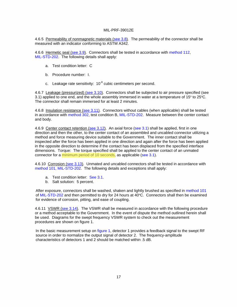
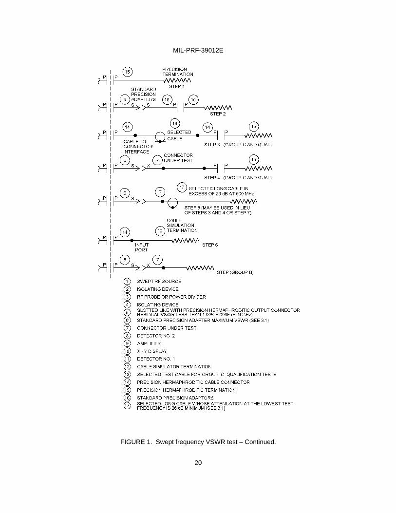
To measure VSWR several sweeps are made with the slotted line probe incrementally positioned over at least a half wave length at the lowest frequency of interest. In this manner an X-Y display is generated whose upper and lower envelope limits represent maximum and minimum amplitudes of the standing wave for each frequency in the test band. A base line may be generated by making a sweep with no input to the measurement channel amplifier. The resultant X-Y display is calibrated according to the characteristics of the measurement channel detector and amplifier, e.g., linear, square law, logarithmic, etc . The VSWR test system is checked out successively terminating the slotted line with the elements shown in steps 1 and 2 and sweeping the frequency over the specified test band (see 3.1). In step 1 the system VSWR shall be less than 1.02 + .004 F (F measured in GHz). In step 2, the system VSWR shall be as specified (see 3.1).
For qualification and group C inspection (see tables II and VII), the system is checked out with the slotted line terminated as in step 3 using the specified cable (see 3.1). The impedance variation (random and/or periodic) from the nominal characteristic impedance specified for the selected test cable should be no more than 1.0 percent when tested by time domain reflectometry. In step 3, the system VSWR shall be as specified (see 3.1). For qualification and group C inspection, the connector under test is measured with the slotted line terminated as in step 4. The VSWR shall be as specified (see 3.1).
Group B inspection tests (see table V) are performed with the slotted line terminated as shown in step 7. The input part of the cable simulator must have the same interface configuration, dimensions, and dielectric as the recommended cable interface for the connector under test. The cable simulator for group B inspection tests must meet the specified VSWR (see 3.1) when tested as shown in step 6.
The standard precision adapter interface shall conform to IEEE Standard 287. Item 6 (standard precision adapters) shall not exceed the specified VSWR requirements (see 3.1). Standard test adapter designs shall be approved by the military qualifying agency.
4.6.12 Connector durability (see 3.15). Each connector under test shall be mated with a typical production connector in accordance with this specification. The connector shall be subjected to the number of cycles of mating and unmating specified (see 3.1). The connector and its mating part shall be completely engaged and completely disengaged during this cycle. Lubrication of the threads or rotational parts shall not be employed for this test unless specified (see 3.1). It is permissible to shake or blow debris from the threads or interface surfaces at intervals of not less than 50 cycles. Solvents or tools shall not be used for cleaning.
MIL-PRF-39012E
19
FIGURE 1. Swept frequency VSWR test.
MIL-PRF-39012E
20
FIGURE 1. Swept frequency VSWR test – Continued.
MIL-PRF-39012E
21
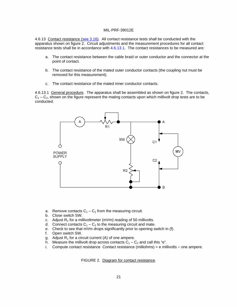
4.6.13 Contact resistance (see 3.16). All contact resistance tests shall be conducted with the apparatus shown on figure 2. Circuit adjustments and the measurement procedures for all contact resistance tests shall be in accordance with 4.6.13.1. The contact resistances to be measured are:
a. The contact resistance between the cable braid or outer conductor and the connector at the
point of contact. b. The contact resistance of the mated outer conductor contacts (the coupling nut must be
removed for this measurement).
c. The contact resistance of the mated inner conductor contacts.
4.6.13.1 General procedure. The apparatus shall be assembled as shown on figure 2. The contacts, C1 – C2, shown on the figure represent the mating contacts upon which millivolt drop tests are to be conducted.
a. Remove contacts C1 – C2 from the measuring circuit. b. Close switch SW. c. Adjust R2 for a millivoltmeter (mVm) reading of 50 millivolts. d. Connect contacts C1 – C2 to the measuring circuit and mate. e. Check to see that mVm drops significantly prior to opening switch in (f). f. Open switch SW. g. Adjust R1 for a circuit current (A) of one ampere. h. Measure the millivolt drop across contacts C1 – C2 and call this “e”. i. Compute contact resistance Contact resistance (milliohms) = e millivolts ÷ one ampere.
FIGURE 2. Diagram for contact resistance.
MIL-PRF-39012E
22
4.6.14 Dielectric withstanding voltage (see 3.17). Connectors shall be tested in accordance with method 301 of MIL-STD-202. The following details shall apply:
a. Special preparation or conditions.
(1) The maximum relative humidity shall be 50 percent. When facilities are not available at this test condition, connectors shall be tested at room ambient relative humidity. In case of dispute, if the test has been made at room ambient relative humidity, retest shall be made at 50 percent maximum relative humidity.
(2) The center contact of plug connectors and receptacle connectors shall be
positioned in such a manner as to simulate actual assembly conditions.
(3) Precautions shall be taken to prevent air-gap voltage breakdowns.
(4) The voltage shall be metered on the high side of the transformer.
b. Magnitude of test voltage (see 3.1): The voltage shall be instantaneously applied. c. Nature of potential: Alternating current.
d. Points of application of test voltage: Between the center contact and body.
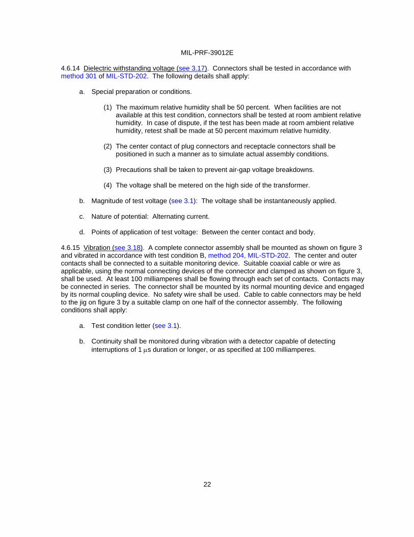
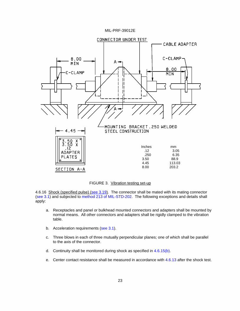
4.6.15 Vibration (see 3.18). A complete connector assembly shall be mounted as shown on figure 3 and vibrated in accordance with test condition B, method 204, MIL-STD-202. The center and outer contacts shall be connected to a suitable monitoring device. Suitable coaxial cable or wire as applicable, using the normal connecting devices of the connector and clamped as shown on figure 3, shall be used. At least 100 milliamperes shall be flowing through each set of contacts. Contacts may be connected in series. The connector shall be mounted by its normal mounting device and engaged by its normal coupling device. No safety wire shall be used. Cable to cable connectors may be held to the jig on figure 3 by a suitable clamp on one half of the connector assembly. The following conditions shall apply:
a. Test condition letter (see 3.1). b. Continuity shall be monitored during vibration with a detector capable of detecting
interruptions of 1 µs duration or longer, or as specified at 100 milliamperes.
MIL-PRF-39012E
23
FIGURE 3. Vibration testing set-up
4.6.16 Shock (specified pulse) (see 3.19). The connector shall be mated with its mating connector (see 3.1) and subjected to method 213 of MIL-STD-202. The following exceptions and details shall apply:
a. Receptacles and panel or bulkhead mounted connectors and adapters shall be mounted by
normal means. All other connectors and adapters shall be rigidly clamped to the vibration table.
b. Acceleration requirements (see 3.1).
c. Three blows in each of three mutually perpendicular planes; one of which shall be parallel
to the axis of the connector.
d. Continuity shall be monitored during shock as specified in 4.6.15(b).
e. Center contact resistance shall be measured in accordance with 4.6.13 after the shock test.
Inches mm .12 3.05 .250 6.35 3.50 88.9 4.45 113.03 8.00 203.2
MIL-PRF-39012E
24
4.6.17 Thermal shock (see 3.20). Connectors shall be subjected to method 107 of MIL-STD-202. The following details shall apply:
a. Test condition letter (see 3.1). b. The contact resistance tests on the center contact shall be performed before and after the
thermal shock test and examined for mechanical damage (see 3.1).
4.6.18 Moisture resistance (see 3.21). The connector shall be mated and cabled with its mating connector and shall be subjected to method 106, MIL-STD-202. The following exceptions and conditions shall apply:
a. No initial measurements. b. No load.
c. Step 7b (vibration) shall be omitted.
d. Measurements shall be made at high humidity when specified (see 3.1).
e. The connector shall withstand the dielectric withstanding voltage specified (see 4.6.14)
after the drying period.
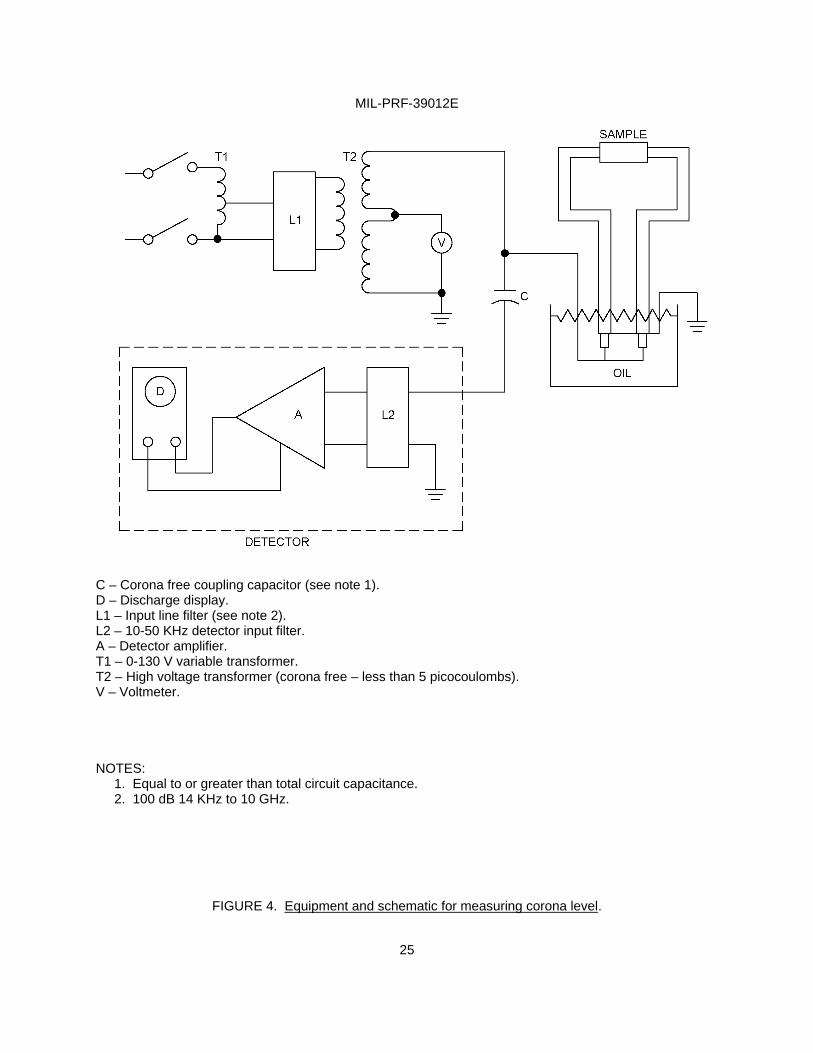
4.6.19 Corona level (see 3.22). The test sample shall be connected to a mating connector and arranged in a suitable test circuit such as indicated on figure 4. Components of the test circuit shall be corona free to the extent that a discharge of five picocoulombs or less can be measured when the 60 Hz test potential is increased to the value specified at the reduced pressure specified (see 3.1). The type of cable and length of cable used shall be as specified (see 3.1). No grease or similar compounds shall be used in or on the test item. After the sample is purged of air, the 60 Hz voltage shall be slowly increased until the detector, operated at a sensitivity of five picocoulombs, indicates a sustained corona discharge. The voltage shall then be decreased until corona is at the five picocoulombs level or less. The latter value is the corona level of the connector under test. The contractor may, at his own option, use a corona detector (which has been approved by the Government) for performing the test in lieu of the test set up on figure 4.
MIL-PRF-39012E
25
C – Corona free coupling capacitor (see note 1). D – Discharge display. L1 – Input line filter (see note 2). L2 – 10-50 KHz detector input filter. A – Detector amplifier. T1 – 0-130 V variable transformer. T2 – High voltage transformer (corona free – less than 5 picocoulombs). V – Voltmeter. NOTES: 1. Equal to or greater than total circuit capacitance. 2. 100 dB 14 KHz to 10 GHz.
FIGURE 4. Equipment and schematic for measuring corona level.
MIL-PRF-39012E
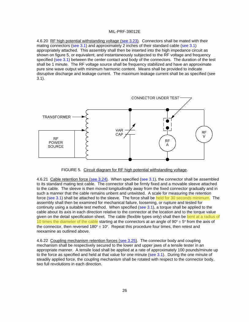
4.6.20 RF high potential withstanding voltage (see 3.23). Connectors shall be mated with their mating connectors (see 3.1) and approximately 2 inches of their standard cable (see 3.1) appropriately attached. This assembly shall then be inserted into the high impedance circuit as shown on figure 5, or equivalent, and instantaneously subjected to the RF voltage and frequency specified (see 3.1) between the center contact and body of the connectors. The duration of the test shall be 1 minute. The RF voltage source shall be frequency stabilized and have an approximate pure sine wave output with minimum harmonic content. Means shall be provided to indicate disruptive discharge and leakage current. The maximum leakage current shall be as specified (see 3.1).
FIGURE 5. Circuit diagram for RF high potential withstanding voltage.
4.6.21 Cable retention force (see 3.24). When specified (see 3.1), the connector shall be assembled to its standard mating test cable. The connector shall be firmly fixed and a movable sleeve attached to the cable. The sleeve is then moved longitudinally away from the fixed connector gradually and in such a manner that the cable remains unbent and untwisted. A scale for measuring the retention force (see 3.1) shall be attached to the sleeve. The force shall be held for 30 seconds minimum. The assembly shall then be examined for mechanical failure, loosening, or rupture and tested for continuity using a suitable test method. When specified (see 3.1), a torque shall be applied to the cable about its axis in each direction relative to the connector at the location and to the torque value given on the detail specification sheet. The cable (flexible types only) shall then be bent at a radius of 10 times the diameter of the cable starting at the connectors at an angle of 90º ± 5º from the axis of the connector, then reversed 180º ± 10º. Repeat this procedure four times, then retest and reexamine as outlined above. 4.6.22 Coupling mechanism retention forces (see 3.25). The connector body and coupling mechanism shall be respectively secured to the lower and upper jaws of a tensile tester in an appropriate manner. A tensile load shall be applied at a rate of approximately 100 pounds/minute up to the force as specified and held at that value for one minute (see 3.1). During the one minute of steadily applied force, the coupling mechanism shall be rotated with respect to the connector body, two full revolutions in each direction.
26
Fred
held for 30 seconds minimum.
Fred
bent at a radius of
Fred
10 times the diameter of the cable

MIL-PRF-39012E
27
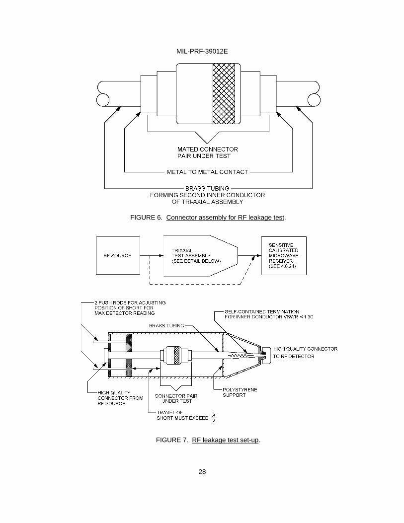
4.6.23 RF leakage (see 3.26). The mating connector pair to be tested shall be assembled as shown on figure 6 and tested as shown on figure 7. (The procedure for determining the dimensions of the cavity on figure 7 may be found in A.3.1 of the appendix). The close fitting brass tubing shall be machined to thread into connector in lieu of compression nut (see 3.1). This test setup between 500 MHz and 11 GHz, shall have a dynamic range from –20 dBm to better than –100 dBm or a difference of 90 dB. Using +20 dBm RF source with 10 dB isolation, an additional 30 dB range can be obtained by use of attenuator pads or a step attenuator producing a total range of 120 dB. The shortening plunger is adjusted to produce a maximum reading in the detector with the triaxial assembly inserted. The insertion loss caused by the insertion of the triaxial assembly adjusted as shown is a measure of the total leakage of the mated connector pair both at its interface as well as at the clamping points to both cables.
Reference “RF Leakage Characteristics of Popular Coaxial Cables and Connectors, 500 MS to 7.5 GHz”, by J. Zorzy and RF Muehlberger, in the Microwave Journal, November 1961, pp 80-86.
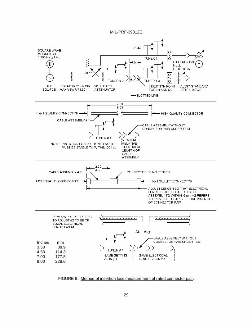
4.6.24 RF insertion loss (see 3.27). The connector shall be tested as shown on figure 8. Insertion loss of a mated connector pair is defined as the increase of a loss due to insertion of a mated connector pair in a cable; this includes the reflection losses to the cable and the dissipating losses in the pair. First insert cable assembly number 1 and tune out its input VSWR by means of tuner number 4 and balance setup. Then insert the cable assembly number 2 which includes the connector pair under test. With tuner number 4 in the same position and the electrical length of the cable assembly the same as that of number 1, record increase of insertion loss; add to this as a correction the cable loss of the removed section due to the length ∆L1 + ∆L2 at this frequency. The sum of the increase and the correction is the insertion loss of the connector pair. Use of alternate test methods may be approved by the qualifying activity.
MIL-PRF-39012E
28
FIGURE 6. Connector assembly for RF leakage test.
FIGURE 7. RF leakage test set-up.
MIL-PRF-39012E
29
FIGURE 8. Method of insertion loss measurement of rated connector pair.
Inches mm 3.50 88.9 4.50 114.3 7.00 177.8 9.00 228.6
MIL-PRF-39012E
30
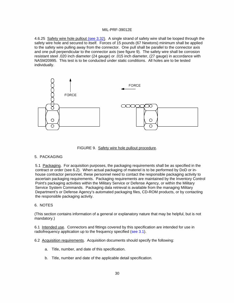
4.6.25 Safety wire hole pullout (see 3.32). A single strand of safety wire shall be looped through the safety wire hole and secured to itself. Forces of 15 pounds (67 Newtons) minimum shall be applied to the safety wire pulling away from the connector. One pull shall be parallel to the connector axis and one pull perpendicular to the connector axis (see figure 9). The safety wire shall be corrosion resistant steel .020 inch diameter (24 gauge) or .015 inch diameter, (27 gauge) in accordance with NASM20995. This test is to be conducted under static conditions. All holes are to be tested individually.
FIGURE 9. Safety wire hole pullout procedure.
5. PACKAGING 5.1 Packaging. For acquisition purposes, the packaging requirements shall be as specified in the contract or order (see 6.2). When actual packaging of materiel is to be performed by DoD or in- house contractor personnel, these personnel need to contact the responsible packaging activity to ascertain packaging requirements. Packaging requirements are maintained by the Inventory Control Point's packaging activities within the Military Service or Defense Agency, or within the Military Service System Commands. Packaging data retrieval is available from the managing Military Department’s or Defense Agency’s automated packaging files, CD-ROM products, or by contacting the responsible packaging activity. 6. NOTES (This section contains information of a general or explanatory nature that may be helpful, but is not mandatory.) 6.1 Intended use. Connectors and fittings covered by this specification are intended for use in radiofrequency application up to the frequency specified (see 3.1). 6.2 Acquisition requirements. Acquisition documents should specify the following:
a. Title, number, and date of this specification. b. Title, number and date of the applicable detail specification.

MIL-PRF-39012E
31
c. The complete PIN of the connector or fitting ordered.
d. For category B connectors, the special tools which are to be used in the assembly of the
connectors. 6.2.1 Packaging. See 5.1.
6.3 Qualification. With respect to products requiring qualification, awards will be made only for products which are, at the time of award of contract, qualified for inclusion in the Qualified Products List QPL N0. 39012 whether or not such products have actually been so listed by that date. The attention of the contractors is called to these requirements, and manufacturers are urged to arrange to have the products that they propose to offer to the Federal Government tested for qualification in order that they may be eligible to be awarded contracts or orders for the products covered by this specification. Information pertaining to qualification of products may be obtained from Defense Supply Center Columbus (DSCC-VQ), P.O. Box 3990, Columbus, Ohio 43218-3990 or email at [email protected] . 6.4 References to superseded specifications. All the requirements of MIL-PRF-39012E are interchangeable with those of MIL-PRF-39012D, therefore, previously existing documents (OEM drawings, etc.) referencing MIL-PRF-39012D need not be changed.
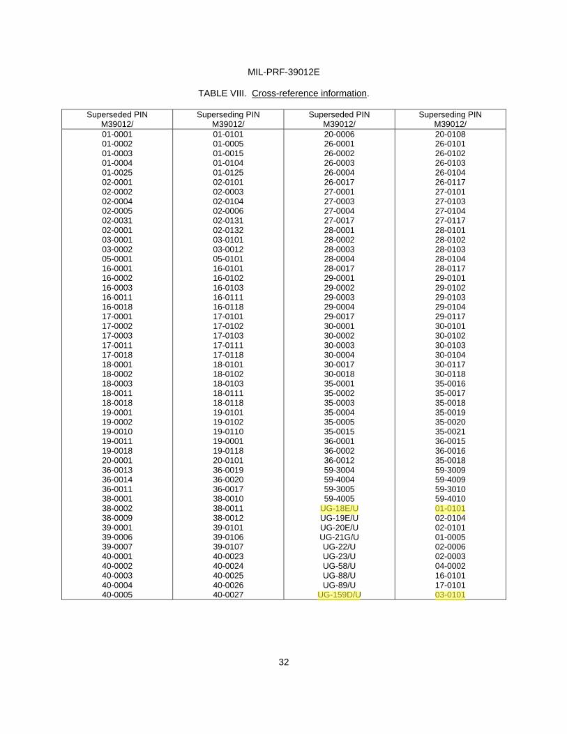
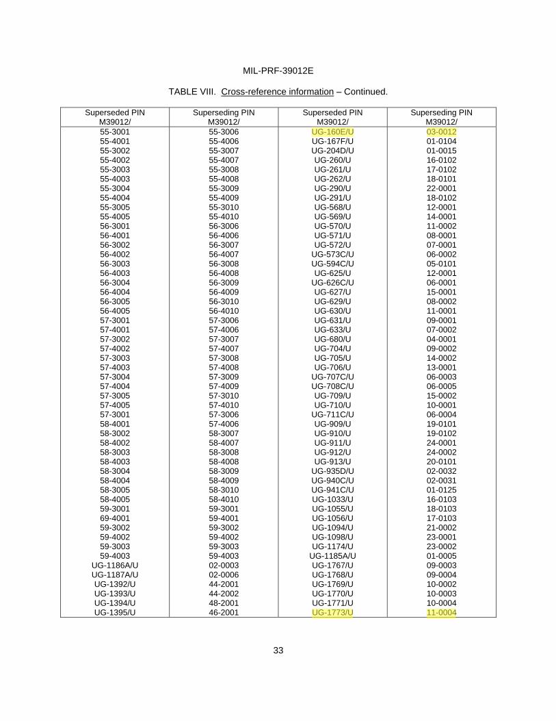
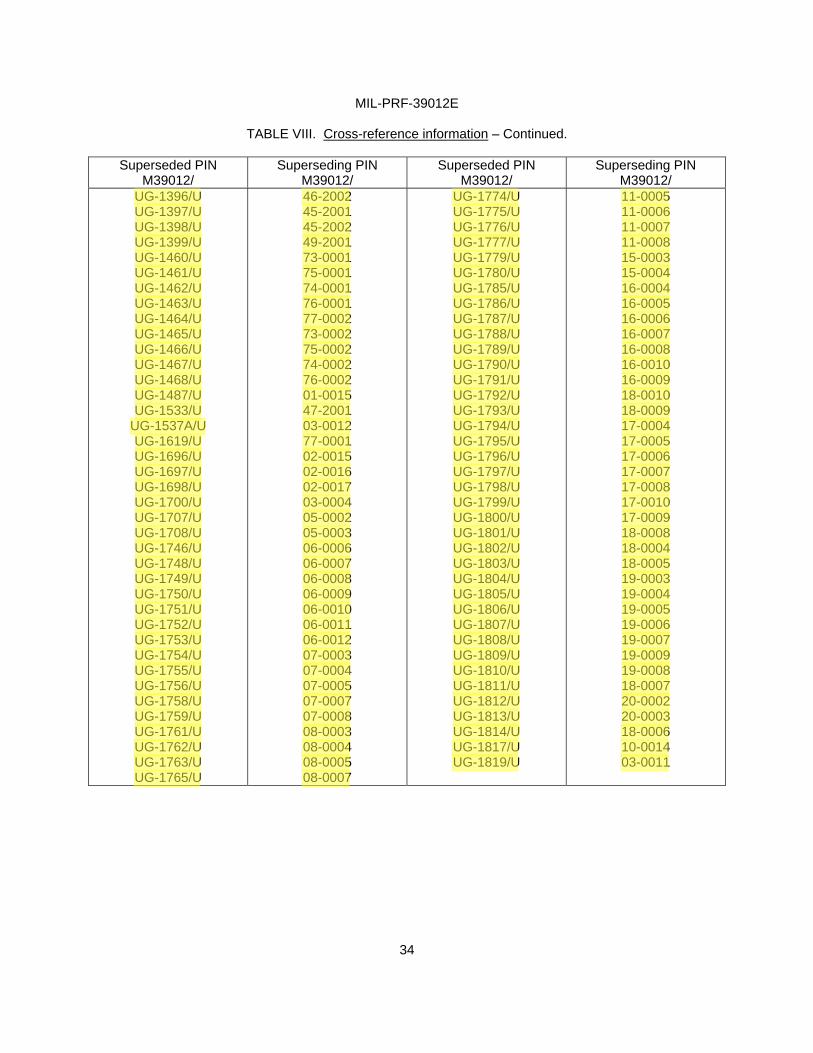
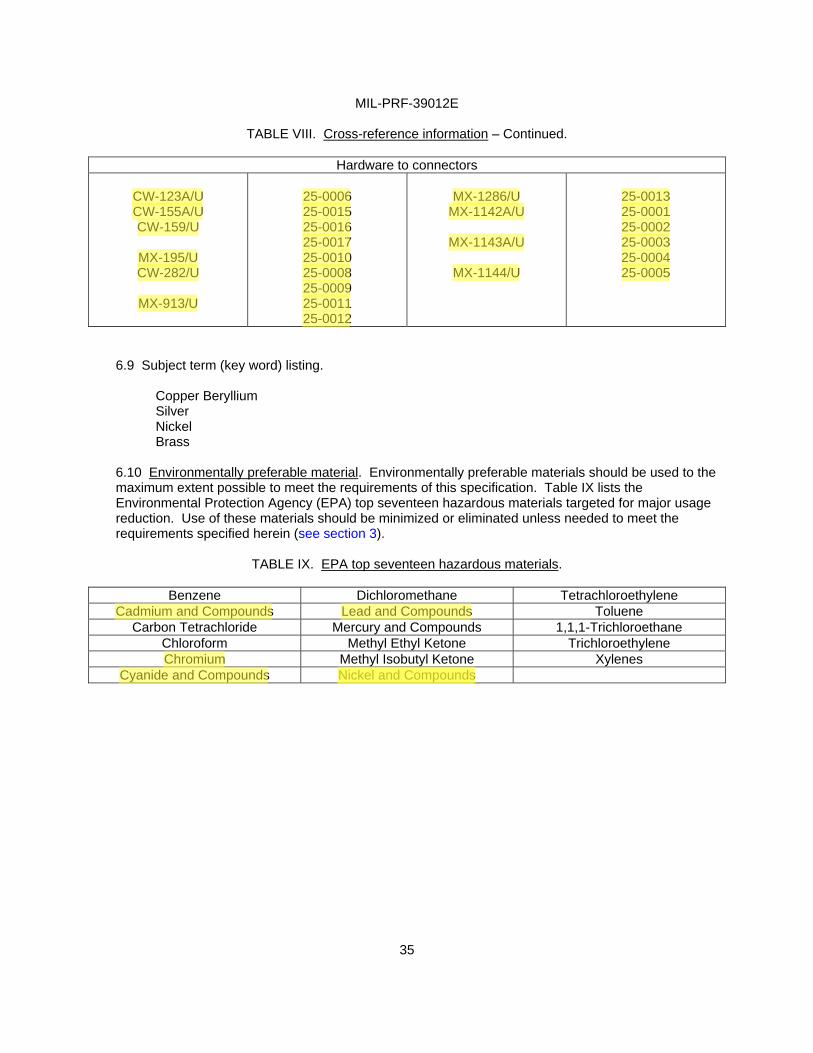
6.5 Cross-reference of PINs. For the substitutability relationship of items covered by this specification and items covered by superseded documents, see table VIII. However, all connectors in stock may be considered interchangeable with the new PIN for a period of 1 year from the effective date of this specification.
6.6 Engineering parameters. The parameters of nominal impedance, voltage rating, frequency range, and temperature range will be as specified. 6.7 Installation of category “B” connectors. Field replaceable connectors for category “B” are those specified on the latest issue of the Qualified Products List and are to be adequate as a replacement without rework of the connector. The equipment parts list is to indicate the appropriate connector that will be used for the service replacement of a category “B” connector.
6.8 Changes from previous issue. Marginal notations are not used in this revision to identify changes with respect to the previous issue due to the extent of the changes.
MIL-PRF-39012E
32
TABLE VIII. Cross-reference information.
Superseded PIN
M39012/ Superseding PIN
M39012/ Superseded PIN
M39012/ Superseding PIN
M39012/ 01-0001 01-0002 01-0003 01-0004 01-0025 02-0001 02-0002 02-0004 02-0005 02-0031 02-0001 03-0001 03-0002 05-0001 16-0001 16-0002 16-0003 16-0011 16-0018 17-0001 17-0002 17-0003 17-0011 17-0018 18-0001 18-0002 18-0003 18-0011 18-0018 19-0001 19-0002 19-0010 19-0011 19-0018 20-0001 36-0013 36-0014 36-0011 38-0001 38-0002 38-0009 39-0001 39-0006 39-0007 40-0001 40-0002 40-0003 40-0004 40-0005
01-0101 01-0005 01-0015 01-0104 01-0125 02-0101 02-0003 02-0104 02-0006 02-0131 02-0132 03-0101 03-0012 05-0101 16-0101 16-0102 16-0103 16-0111 16-0118 17-0101 17-0102 17-0103 17-0111 17-0118 18-0101 18-0102 18-0103 18-0111 18-0118 19-0101 19-0102 19-0110 19-0001 19-0118 20-0101 36-0019 36-0020 36-0017 38-0010 38-0011 38-0012 39-0101 39-0106 39-0107 40-0023 40-0024 40-0025 40-0026 40-0027
20-0006 26-0001 26-0002 26-0003 26-0004 26-0017 27-0001 27-0003 27-0004 27-0017 28-0001 28-0002 28-0003 28-0004 28-0017 29-0001 29-0002 29-0003 29-0004 29-0017 30-0001 30-0002 30-0003 30-0004 30-0017 30-0018 35-0001 35-0002 35-0003 35-0004 35-0005 35-0015 36-0001 36-0002 36-0012 59-3004 59-4004 59-3005 59-4005
UG-18E/U UG-19E/U UG-20E/U UG-21G/U UG-22/U UG-23/U UG-58/U UG-88/U UG-89/U
UG-159D/U
20-0108 26-0101 26-0102 26-0103 26-0104 26-0117 27-0101 27-0103 27-0104 27-0117 28-0101 28-0102 28-0103 28-0104 28-0117 29-0101 29-0102 29-0103 29-0104 29-0117 30-0101 30-0102 30-0103 30-0104 30-0117 30-0118 35-0016 35-0017 35-0018 35-0019 35-0020 35-0021 36-0015 36-0016 35-0018 59-3009 59-4009 59-3010 59-4010 01-0101 02-0104 02-0101 01-0005 02-0006 02-0003 04-0002 16-0101 17-0101 03-0101
Fred
UG-18E/U 01-0101
Fred
UG-159D/U 03-0101
MIL-PRF-39012E
33
TABLE VIII. Cross-reference information – Continued.
Superseded PIN
M39012/ Superseding PIN
M39012/ Superseded PIN
M39012/ Superseding PIN
M39012/ 55-3001 55-4001 55-3002 55-4002 55-3003 55-4003 55-3004 55-4004 55-3005 55-4005 56-3001 56-4001 56-3002 56-4002 56-3003 56-4003 56-3004 56-4004 56-3005 56-4005 57-3001 57-4001 57-3002 57-4002 57-3003 57-4003 57-3004 57-4004 57-3005 57-4005 57-3001 58-4001 58-3002 58-4002 58-3003 58-4003 58-3004 58-4004 58-3005 58-4005 59-3001 69-4001 59-3002 59-4002 59-3003 59-4003
UG-1186A/U UG-1187A/U UG-1392/U UG-1393/U UG-1394/U UG-1395/U
55-3006 55-4006 55-3007 55-4007 55-3008 55-4008 55-3009 55-4009 55-3010 55-4010 56-3006 56-4006 56-3007 56-4007 56-3008 56-4008 56-3009 56-4009 56-3010 56-4010 57-3006 57-4006 57-3007 57-4007 57-3008 57-4008 57-3009 57-4009 57-3010 57-4010 57-3006 57-4006 58-3007 58-4007 58-3008 58-4008 58-3009 58-4009 58-3010 58-4010 59-3001 59-4001 59-3002 59-4002 59-3003 59-4003 02-0003 02-0006 44-2001 44-2002 48-2001 46-2001
UG-160E/U UG-167F/U UG-204D/U UG-260/U UG-261/U UG-262/U UG-290/U UG-291/U UG-568/U UG-569/U UG-570/U UG-571/U UG-572/U
UG-573C/U UG-594C/U UG-625/U
UG-626C/U UG-627/U UG-629/U UG-630/U UG-631/U UG-633/U UG-680/U UG-704/U UG-705/U UG-706/U
UG-707C/U UG-708C/U UG-709/U UG-710/U
UG-711C/U UG-909/U UG-910/U UG-911/U UG-912/U UG-913/U
UG-935D/U UG-940C/U UG-941C/U UG-1033/U UG-1055/U UG-1056/U UG-1094/U UG-1098/U UG-1174/U
UG-1185A/U UG-1767/U UG-1768/U UG-1769/U UG-1770/U UG-1771/U UG-1773/U
03-0012 01-0104 01-0015 16-0102 17-0102 18-0101 22-0001 18-0102 12-0001 14-0001 11-0002 08-0001 07-0001 06-0002 05-0101 12-0001 06-0001 15-0001 08-0002 11-0001 09-0001 07-0002 04-0001 09-0002 14-0002 13-0001 06-0003 06-0005 15-0002 10-0001 06-0004 19-0101 19-0102 24-0001 24-0002 20-0101 02-0032 02-0031 01-0125 16-0103 18-0103 17-0103 21-0002 23-0001 23-0002 01-0005 09-0003 09-0004 10-0002 10-0003 10-0004 11-0004
Fred
UG-160E/U 03-0012
Fred
UG-1773/U 11-0004
MIL-PRF-39012E
34
TABLE VIII. Cross-reference information – Continued.
Superseded PIN
M39012/ Superseding PIN
M39012/ Superseded PIN
M39012/ Superseding PIN
M39012/ UG-1396/U UG-1397/U UG-1398/U UG-1399/U UG-1460/U UG-1461/U UG-1462/U UG-1463/U UG-1464/U UG-1465/U UG-1466/U UG-1467/U UG-1468/U UG-1487/U UG-1533/U
UG-1537A/U UG-1619/U UG-1696/U UG-1697/U UG-1698/U UG-1700/U UG-1707/U UG-1708/U UG-1746/U UG-1748/U UG-1749/U UG-1750/U UG-1751/U UG-1752/U UG-1753/U UG-1754/U UG-1755/U UG-1756/U UG-1758/U UG-1759/U UG-1761/U UG-1762/U UG-1763/U UG-1765/U
46-2002 45-2001 45-2002 49-2001 73-0001 75-0001 74-0001 76-0001 77-0002 73-0002 75-0002 74-0002 76-0002 01-0015 47-2001 03-0012 77-0001 02-0015 02-0016 02-0017 03-0004 05-0002 05-0003 06-0006 06-0007 06-0008 06-0009 06-0010 06-0011 06-0012 07-0003 07-0004 07-0005 07-0007 07-0008 08-0003 08-0004 08-0005 08-0007
UG-1774/U UG-1775/U UG-1776/U UG-1777/U UG-1779/U UG-1780/U UG-1785/U UG-1786/U UG-1787/U UG-1788/U UG-1789/U UG-1790/U UG-1791/U UG-1792/U UG-1793/U UG-1794/U UG-1795/U UG-1796/U UG-1797/U UG-1798/U UG-1799/U UG-1800/U UG-1801/U UG-1802/U UG-1803/U UG-1804/U UG-1805/U UG-1806/U UG-1807/U UG-1808/U UG-1809/U UG-1810/U UG-1811/U UG-1812/U UG-1813/U UG-1814/U UG-1817/U UG-1819/U
11-0005 11-0006 11-0007 11-0008 15-0003 15-0004 16-0004 16-0005 16-0006 16-0007 16-0008 16-0010 16-0009 18-0010 18-0009 17-0004 17-0005 17-0006 17-0007 17-0008 17-0010 17-0009 18-0008 18-0004 18-0005 19-0003 19-0004 19-0005 19-0006 19-0007 19-0009 19-0008 18-0007 20-0002 20-0003 18-0006 10-0014 03-0011
Fred
UG-1396/U 46-2002 UG-1774/U 11-0005
Fred
UG-1397/U UG-1398/U UG-1399/U UG-1460/U UG-1461/U UG-1462/U UG-1463/U UG-1464/U UG-1465/U UG-1466/U UG-1467/U UG-1468/U UG-1487/U UG-1533/U UG-1537A/U UG-1619/U UG-1696/U UG-1697/U UG-1698/U UG-1700/U UG-1707/U UG-1708/U UG-1746/U UG-1748/U UG-1749/U UG-1750/U UG-1751/U UG-1752/U UG-1753/U UG-1754/U UG-1755/U UG-1756/U UG-1758/U UG-1759/U UG-1761/U 45-2001 45-2002 49-2001 73-0001 75-0001 74-0001 76-0001 77-0002 73-0002 75-0002 74-0002 76-0002 01-0015 47-2001 03-0012 77-0001 02-0015 02-0016 02-0017 03-0004 05-0002 05-0003 06-0006 06-0007 06-0008 06-0009 06-0010 06-0011 06-0012 07-0003 07-0004 07-0005 07-0007 07-0008 08-0003 UG-1775/U UG-1776/U UG-1777/U UG-1779/U UG-1780/U UG-1785/U UG-1786/U UG-1787/U UG-1788/U UG-1789/U UG-1790/U UG-1791/U UG-1792/U UG-1793/U UG-1794/U UG-1795/U UG-1796/U UG-1797/U UG-1798/U UG-1799/U UG-1800/U UG-1801/U UG-1802/U UG-1803/U UG-1804/U UG-1805/U UG-1806/U UG-1807/U UG-1808/U UG-1809/U UG-1810/U UG-1811/U UG-1812/U UG-1813/U UG-1814/U 11-0006 11-0007 11-0008 15-0003 15-0004 16-0004 16-0005 16-0006 16-0007 16-0008 16-0010 16-0009 18-0010 18-0009 17-0004 17-0005 17-0006 17-0007 17-0008 17-0010 17-0009 18-0008 18-0004 18-0005 19-0003 19-0004 19-0005 19-0006 19-0007 19-0009 19-0008 18-0007 20-0002 20-0003
Fred
UG-1762/U UG-1763/U UG-1765/U 08-0004 08-0005 08-0007 UG-1817/U UG-1819/U 18-0006 10-0014 03-0011
MIL-PRF-39012E
35
TABLE VIII. Cross-reference information – Continued.
Hardware to connectors
CW-123A/U CW-155A/U CW-159/U
MX-195/U CW-282/U
MX-913/U
25-0006 25-0015 25-0016 25-0017 25-0010 25-0008 25-0009 25-0011 25-0012
MX-1286/U
MX-1142A/U
MX-1143A/U
MX-1144/U
25-0013 25-0001 25-0002 25-0003 25-0004 25-0005
6.9 Subject term (key word) listing. Copper Beryllium Silver Nickel Brass
6.10 Environmentally preferable material. Environmentally preferable materials should be used to the maximum extent possible to meet the requirements of this specification. Table IX lists the Environmental Protection Agency (EPA) top seventeen hazardous materials targeted for major usage reduction. Use of these materials should be minimized or eliminated unless needed to meet the requirements specified herein (see section 3).
TABLE IX. EPA top seventeen hazardous materials.
Benzene Dichloromethane Tetrachloroethylene
Cadmium and Compounds Lead and Compounds Toluene Carbon Tetrachloride Mercury and Compounds 1,1,1-Trichloroethane
Chloroform Methyl Ethyl Ketone Trichloroethylene Chromium Methyl Isobutyl Ketone Xylenes
Cyanide and Compounds Nickel and Compounds
Fred
CW-123A/U CW-155A/U CW-159/U MX-195/U CW-282/U MX-913/U 25-0006 25-0015 25-0016 25-0017 25-0010 25-0008 25-0009 25-0011 25-0012 MX-1286/U MX-1142A/U MX-1143A/U MX-1144/U 25-0013 25-0001 25-0002 25-0003 25-0004 25-0005
Fred
Cadmium and Compounds
Fred
Lead and Compounds
Fred
Chromium
Fred
Nickel and Compounds
Fred
Cyanide and Compounds Nickel and Compounds

MIL-PRF-39012E
36
APPENDIX A
ADDITIONAL INFORMATION ON TEST PROCEDURES
A.1 SCOPE A.1.1 Scope. This appendix is a mandatory part of this specification. The information contained herein is intended for compliance. This appendix is to provide additional information to the user of this specification in performing the voltage standing wave ratio, RF leakage, and insertion loss tests. A.2 TEST TYPES A.2.1 Voltage standing wave ratio (see 4.6.11). A.2.1.1 Test connector. The standard test-connector interface shall be in accordance with MIL-STD-348. The standard test connector impedance shall be 50 ± 0.5 ohms. A.3 MEASUREMENTS A.3.1 RF leakage (see 4.6.23). A.3.1.1 Measurement technique. The measurement of the leakage from connectors is performed by collecting the leakage energy in a coaxial system surrounding the leakage source. An outline of the instrumentation is shown on figure 7. The device from which leakage is to be measured is incorporated on a uniform transmission line which is terminated in a matched load. The matched termination simplifies both the measurement procedure and data reduction. This complete coaxial system is embodied within a cylinder which forms, externally, a second coaxial system. The second coaxial system is terminated at one end in an adjustable short-circulating plunger and at the other in a tapered transition terminated in a matched detector.
For direct leakage measurements the adjustable short circuit serves several purposes.
The short-circuit position is adjusted to assure that an adequately low impedance appears behind the equivalent leakage generator. A matched termination can be substituted, but the resulting 6-dB loss cannot be tolerated in some cases. In addition, if the leakage source is directional, as it indeed is for connectors with multiple leakage, it is possible for the leakage to be directed to this termination at some frequencies and not collected by the detector. For surface transfer-impedance measurements on connectors with leakage from more than one point in the connector, however, a matched termination is desirable in order to simplify the transformation of the measured data to absolute transfer impedance data. This is not needed to make relative comparisons in this test.
The equivalent leakage generator, in general, can have field components in the radial, axial, and circumferential* directions. Furthermore, these components are not necessarily circularly symmetric. Locally, TE, TM, and TEM modes can all exist, and in fact, for complete leakage measurements, the detector should couple to all but the measurement is more complex in this case. The excitation of the outer coaxial line, however, is believed to be principally TEM, since the currents in the internal line are predominantly axial and symmetric. It is however, possible to have a symmetrical leakage current which can generate the above mentioned modes. It is recommended that all measurements be made below the frequency that the higher order modes can propagate in the outer coaxial line.
The characteristic impedance of the outer coaxial line of the tri-axial system, which is formed with the inner conductor, should be matched to the detector. 50-ohm coaxial circuits are generally desired for convenience.
MIL-PRF-39012E
37
APPENDIX A
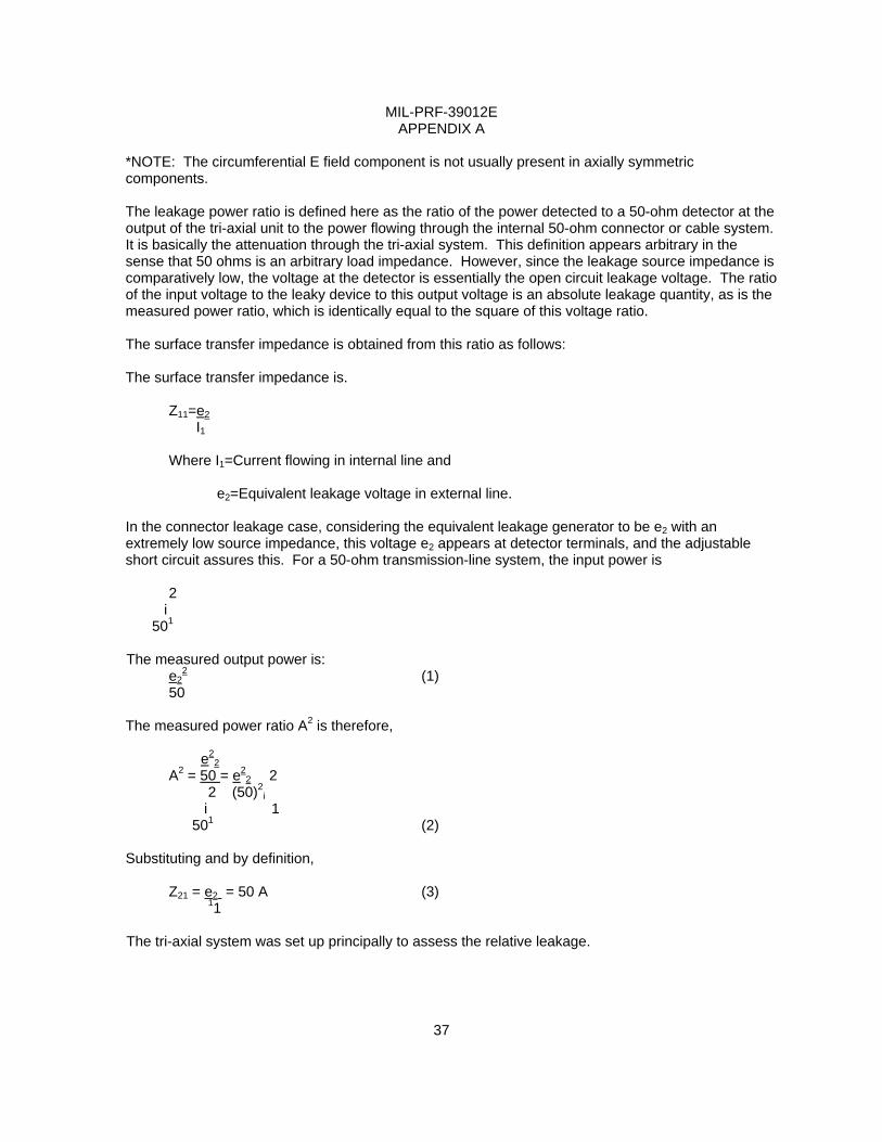
*NOTE: The circumferential E field component is not usually present in axially symmetric components.
The leakage power ratio is defined here as the ratio of the power detected to a 50-ohm detector at the output of the tri-axial unit to the power flowing through the internal 50-ohm connector or cable system. It is basically the attenuation through the tri-axial system. This definition appears arbitrary in the sense that 50 ohms is an arbitrary load impedance. However, since the leakage source impedance is comparatively low, the voltage at the detector is essentially the open circuit leakage voltage. The ratio of the input voltage to the leaky device to this output voltage is an absolute leakage quantity, as is the measured power ratio, which is identically equal to the square of this voltage ratio.
The surface transfer impedance is obtained from this ratio as follows:
The surface transfer impedance is.
Z11=e2 I1
Where I1=Current flowing in internal line and e2=Equivalent leakage voltage in external line.
In the connector leakage case, considering the equivalent leakage generator to be e2 with an extremely low source impedance, this voltage e2 appears at detector terminals, and the adjustable short circuit assures this. For a 50-ohm transmission-line system, the input power is
2 i 501
The measured output power is:
e22 (1)
50
The measured power ratio A2 is therefore, e2
2 A2 = 50 = e2
2 2 2 (50)2
i i 1 501 (2)
Substituting and by definition, Z21 = e2 = 50 A (3) 11
The tri-axial system was set up principally to assess the relative leakage.

MIL-PRF-39012E
38
APPENDIX A A.3.1.2 Measurement procedure. In measuring the leakage power ratio, A2, basically a substitution technique is employed. A matched detector system is installed at the output connector of the tri-axial unit, and the unit is driven as shown on figure 7. In this set-up, the short circuit is adjusted to produce a maximum indication at the detector. The detector is then connected directly to the source and the change of attenuation required to yield the initial detector level, is measured.
The sensitivity of this system is obviously limited by the sensitivity of the detector and the power available. A sensitive parallel IF substitution system is employed, and for the low leakage configuration about 100 milliwatts of power is required.
The principal sources of error are attenuator errors and mismatch at the receiver (mixer) input. For connector measurements, the error due to mismatch is directly proportional to VSWR since the equivalent leakage source impedance is small. The indicated leakage power can vary between the extremes. PxVSWR to P + VSWR, where P is the power that would be delivered to a matched system. A VSWR of 2 will produce ± 3 –dB error therefore.
In advance of installing the inner coaxial system into the outer of the tri-axial system, the inner system may be excited, and the immediate vicinity of the leakage point or associated connector and attachment points probed with a small loop or dipole to establish how critical the mating, the connector and joints are.
A.4 RF insertion loss (see 4.6.23).
A.4.1 The following procedure may be used when performing the insertion loss test of 4.6.24: Assemble one 8” ± 1” long cable assembly terminated in a male and female test connector. Record its relative electrical length. Tune out its input VSWR using tuner number 4. Do not disturb tuner. For N, C, SC use M17/75-RG214 and “N” test connectors. For BNC, TNC, and TPS, use solid copper shield cable equivalent of M17/111-RG303 (Coaxitube number 1163.T1403-20 of Precision Tube Co.) and TNC connectors. Measure insertion loss L1 of tuner number 4 and test cable.
Insert the connector pair to be tested in the middle, remove enough so that the electrical length is the same as above within 0.05 cm, record ∆l1 + ∆l2 the total length of dielectric removed; keep tuner number 4 in the same position as above. Measure insertion loss L2 of tuner number 4 and test cable including connector pair.
Measure attenuation of 50 feet of test cable and compute loss α per inch Lc = L2 – L1 + a (∆l1 = ∆l2).
MIL-PRF-39012E
39
APPENDIX B
ADDITIONAL INFORMATION ON CABLE GROUPINGS
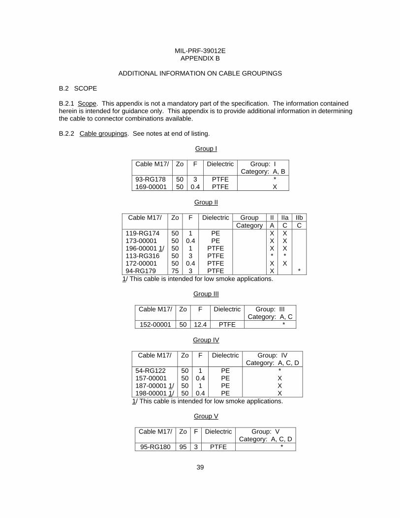
B.2 SCOPE B.2.1 Scope. This appendix is not a mandatory part of the specification. The information contained herein is intended for guidance only. This appendix is to provide additional information in determining the cable to connector combinations available. B.2.2 Cable groupings. See notes at end of listing.
Group I
Cable M17/ Zo F Dielectric Group: I Category: A, B
93-RG178 169-00001
50 50
3 0.4
PTFE PTFE
* X
Group II
Group II IIa IIb Cable M17/ Zo F Dielectric
Category A C C 119-RG174 173-00001 196-00001 1/113-RG316 172-00001 94-RG179
50 50 50 50 50 75
1 0.41 3
0.43
PE PE
PTFE PTFE PTFE PTFE
XXX* XX
X X X * X
*
1/ This cable is intended for low smoke applications.
Group III
Cable M17/ Zo F Dielectric Group: III Category: A, C
152-00001 50 12.4 PTFE *
Group IV
Cable M17/ Zo F Dielectric Group: IV Category: A, C, D
54-RG122 157-00001 187-00001 1/198-00001 1/
50 50 50 50
1 0.41
0.4
PE PE PE PE
* X X X
1/ This cable is intended for low smoke applications.
Group V
Cable M17/ Zo F Dielectric Group: V Category: A, C, D
95-RG180 95 3 PTFE *
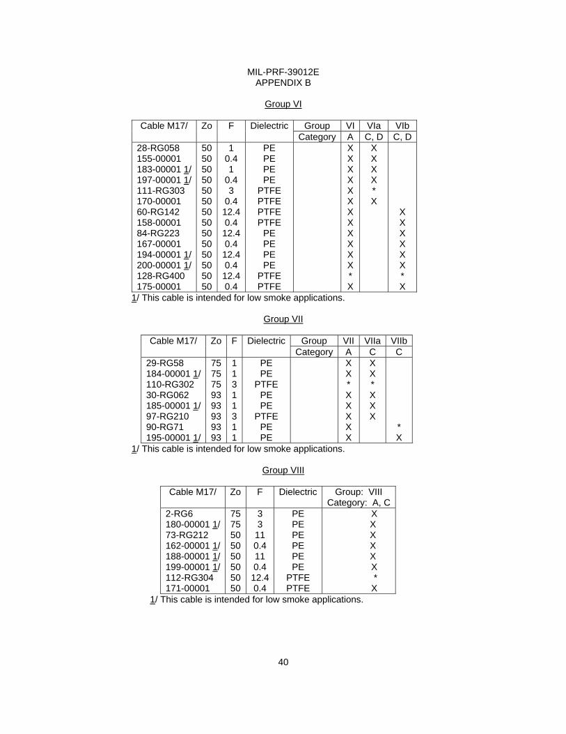
MIL-PRF-39012E
40
APPENDIX B
Group VI
Group VI VIa VIb Cable M17/ Zo F DielectricCategory A C, D C, D
28-RG058 155-00001 183-00001 1/ 197-00001 1/ 111-RG303 170-00001 60-RG142 158-00001 84-RG223 167-00001 194-00001 1/ 200-00001 1/ 128-RG400 175-00001
50 50 50 50 50 50 50 50 50 50 50 50 50 50
1 0.4 1
0.4 3
0.4 12.40.4 12.40.4 12.40.4 12.40.4
PE PE PE PE
PTFE PTFE PTFE PTFE
PE PE PE PE
PTFE PTFE
X X X X X X X X X X X X * X
X X X X * X
X X X X X X * X
1/ This cable is intended for low smoke applications.
Group VII
Group VII VIIa VIIb Cable M17/ Zo F DielectricCategory A C C
29-RG58 184-00001 1/ 110-RG302 30-RG062 185-00001 1/ 97-RG210 90-RG71 195-00001 1/
75 75 75 93 93 93 93 93
1 1 3 1 1 3 1 1
PE PE
PTFE PE PE
PTFE PE PE
X X * X X X X X
X X * X X X
* X
1/ This cable is intended for low smoke applications.
Group VIII
Cable M17/ Zo F Dielectric Group: VIII Category: A, C
2-RG6 180-00001 1/ 73-RG212 162-00001 1/ 188-00001 1/ 199-00001 1/ 112-RG304 171-00001
75 75 50 50 50 50
3 PE X 3 PE X
11 PE X 0.4 PE X 11 PE X 0.4 PE X
50 12.4 PTFE * 50 0.4 PTFE X
1/ This cable is intended for low smoke applications.
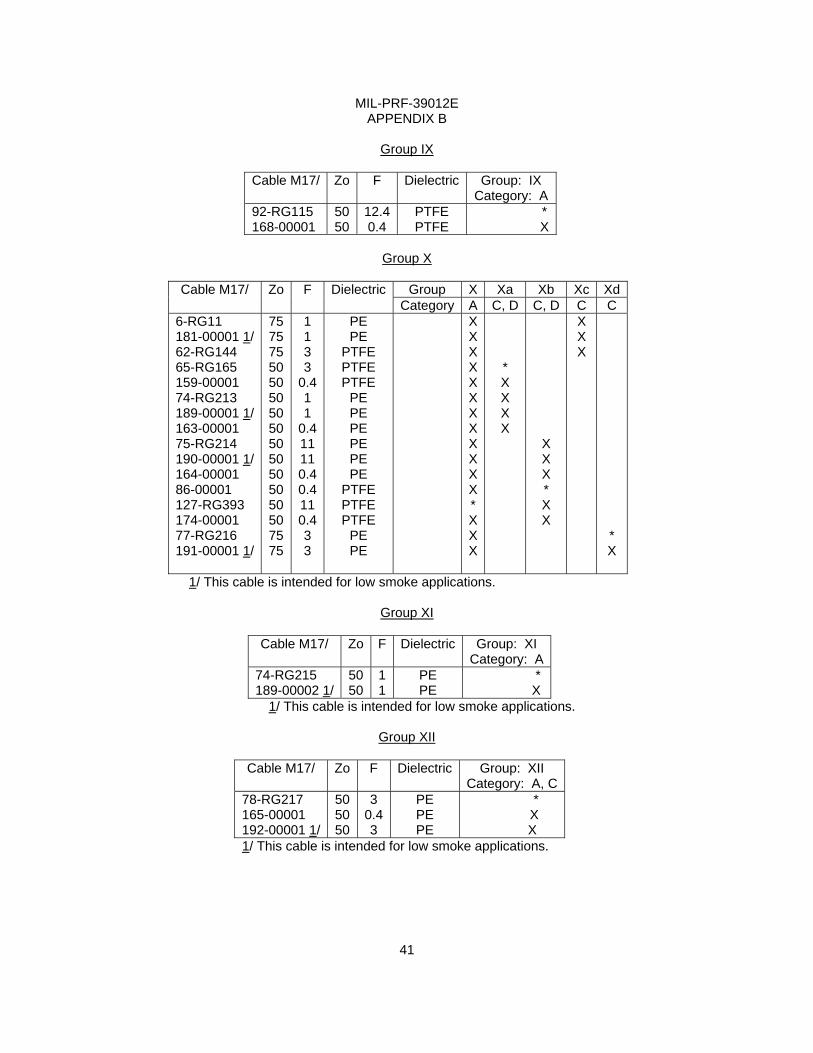
MIL-PRF-39012E
41
APPENDIX B
Group IX
Cable M17/ Zo F Dielectric Group: IX Category: A
92-RG115 168-00001
50 50
12.40.4
PTFE PTFE
* X
Group X
Group X Xa Xb Xc Xd Cable M17/ Zo F Dielectric
Category A C, D C, D C C 6-RG11 181-00001 1/ 62-RG144 65-RG165 159-00001 74-RG213 189-00001 1/ 163-00001 75-RG214 190-00001 1/ 164-00001 86-00001 127-RG393 174-00001 77-RG216 191-00001 1/
75 75 75 50 50 50 50 50 50 50 50 50 50 50 75 75
1 1 3 3
0.4 1 1
0.4 11 11 0.4 0.4 11 0.4 3 3
PE PE
PTFE PTFE PTFE
PE PE PE PE PE PE
PTFE PTFE PTFE
PE PE
XXXXXXXXXXXX* XXX
* X X X X
X X X * X X
X X X
* X
1/ This cable is intended for low smoke applications.
Group XI
Cable M17/ Zo F Dielectric Group: XI Category: A
74-RG215 189-00002 1/
50 50
1 1
PE PE
* X
1/ This cable is intended for low smoke applications.
Group XII
Cable M17/ Zo F Dielectric Group: XII Category: A, C
78-RG217 165-00001 192-00001 1/
50 50 50
3 0.43
PE PE PE
* X X
1/ This cable is intended for low smoke applications.
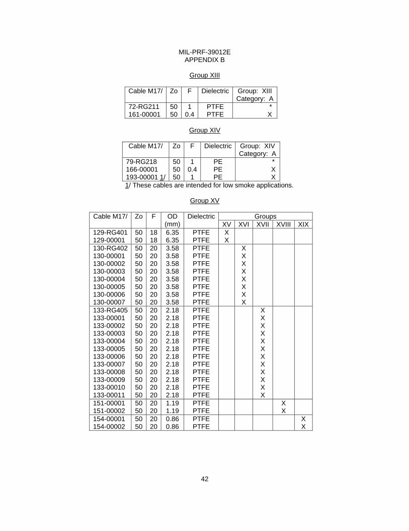
MIL-PRF-39012E
42
APPENDIX B
Group XIII
Cable M17/ Zo F Dielectric Group: XIII Category: A
72-RG211 161-00001
50 50
1 0.4
PTFE PTFE
* X
Group XIV
Cable M17/ Zo F Dielectric Group: XIV
Category: A79-RG218 166-00001 193-00001 1/
50 50 50
1 0.41
PE PE PE
* X X
1/ These cables are intended for low smoke applications.
Group XV
Groups Cable M17/ Zo F OD (mm)
DielectricXV XVI XVII XVIII XIX
129-RG401 129-00001
50 50
18 18
6.35 6.35
PTFE PTFE
X X
130-RG402 130-00001 130-00002 130-00003 130-00004 130-00005 130-00006 130-00007
50 50 50 50 50 50 50 50
20 20 20 20 20 20 20 20
3.58 3.58 3.58 3.58 3.58 3.58 3.58 3.58
PTFE PTFE PTFE PTFE PTFE PTFE PTFE PTFE
X X X X X X X X
133-RG405 133-00001 133-00002 133-00003 133-00004 133-00005 133-00006 133-00007 133-00008 133-00009 133-00010 133-00011
50 50 50 50 50 50 50 50 50 50 50 50
20 20 20 20 20 20 20 20 20 20 20 20
2.18 2.18 2.18 2.18 2.18 2.18 2.18 2.18 2.18 2.18 2.18 2.18
PTFE PTFE PTFE PTFE PTFE PTFE PTFE PTFE PTFE PTFE PTFE PTFE
X X X X X X X X X X X X
151-00001 151-00002
50 50
20 20
1.19 1.19
PTFE PTFE
X X
154-00001 154-00002
50 50
20 20
0.86 0.86
PTFE PTFE
X X
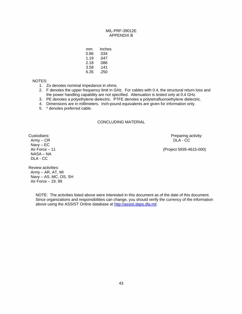
MIL-PRF-39012E
APPENDIX B mm Inches
0.86 .034 1.19 .047 2.18 .086 3.58 .141 6.35 .250
NOTES:
1. Zo denotes nominal impedance in ohms. 2. F denotes the upper frequency limit in GHz. For cables with 0.4, the structural return loss and
the power handling capability are not specified. Attenuation is tested only at 0.4 GHz. 3. PE denotes a polyethylene dielectric. PTFE denotes a polytetrafluoroethylene dielectric. 4. Dimensions are in millimeters. Inch-pound equivalents are given for information only. 5. * denotes preferred cable.
CONCLUDING MATERIAL
Custodians: Preparing activity: Army – CR DLA - CC Navy – EC Air Force – 11 (Project 5935-4615-000) NASA – NA DLA - CC Review activities: Army – AR, AT, MI Navy – AS, MC, OS, SH Air Force – 19, 99
NOTE: The activities listed above were interested in this document as of the date of this document. Since organizations and responsibilities can change, you should verify the currency of the information above using the ASSIST Online database at http://assist.daps.dla.mil.
43