INCH-POUND MIL-PRF-22885/112
21
AMSC N/A FSC 5930 INCH-POUND MIL-PRF-22885/112 1 April 2005 PERFORMANCE SPECIFICATION SHEET SWITCHES, PUSHBUTTON, WHITE LIGHT EMITTING DIODE (LED) ILLUMINATED, STANDARD, NIGHT VISION IMAGING SYSTEM (NVIS) AND SUNLIGHT READABLE DISPLAYS, DIMMABLE, SPDT AND DPDT, LOW LEVEL TO 7 AMPERES, SEALED AND UNSEALED, SOLDER AND COMMON TERMINATION SYSTEM (CTS) TERMINATIONS This specification is approved for use by all Departments and Agencies of the Department of Defense. The complete requirements for acquiring the switch described herein shall consist of this specification and the latest issue of MIL-PRF-22885. NOTES 1. Dimensions are in inches. 2. Metric equivalents are given for general information only. 3. Unless otherwise specified, tolerance is ± .03. 4. Pushbutton design shall provide a means to prevent incorrect installation and a means of retention with switch body during service. 5. See figure 8 for recommended mounting panel cutouts and thickness ranges. Inches .03 .14 .20 mm 0.8 3.6 5.1 Inches .24 .35 mm 6.1 8.9 Inches .39 .52 mm 9.9 13.2 Inches .75 1.21 mm 19.1 30.7 FIGURE 1. Switches - type I (unsealed, solder terminals) and type II (dripproof seal(s), solder terminals) .
Transcript of INCH-POUND MIL-PRF-22885/112
AMSC N/A FSC 5930
INCH-POUND MIL-PRF-22885/112 1 April 2005
PERFORMANCE SPECIFICATION SHEET
SWITCHES, PUSHBUTTON, WHITE LIGHT EMITTING DIODE (LED) ILLUMINATED, STANDARD, NIGHT VISION IMAGING SYSTEM (NVIS) AND SUNLIGHT READABLE DISPLAYS, DIMMABLE, SPDT
AND DPDT, LOW LEVEL TO 7 AMPERES, SEALED AND UNSEALED, SOLDER AND COMMON TERMINATION SYSTEM (CTS) TERMINATIONS
This specification is approved for use by all
Departments and Agencies of the Department of Defense.
The complete requirements for acquiring the switch described herein shall consist of this specification and the latest issue of MIL-PRF-22885.
NOTES 1. Dimensions are in inches. 2. Metric equivalents are given for general information only. 3. Unless otherwise specified, tolerance is ± .03. 4. Pushbutton design shall provide a means to prevent incorrect installation and a means of
retention with switch body during service. 5. See figure 8 for recommended mounting panel cutouts and thickness ranges.
Inches
.03
.14
.20
mm 0.8 3.6 5.1
Inches .24 .35
mm 6.18.9
Inches .39 .52
mm 9.9
13.2
Inches .75
1.21
mm 19.1 30.7
FIGURE 1. Switches - type I (unsealed, solder terminals) and type II (dripproof seal(s), solder terminals).
MIL-PRF-22885/112
2
NOTES:
1. Dimensions are in inches. 2. Metric equivalents are given for general information only. 3. Unless otherwise specified, tolerance is ± .03. 4. Pushbutton design shall provide a means to prevent incorrect installation and a means of
retention with switch body during service. 5. See figure 8 for recommended mounting panel cutouts and thickness ranges.
Inches .03 .14
mm 0.8 3.6
Inches .24 .43
mm 6.1
10.9
Inches .45 .52
mm 11.413.2
Inches .90
1.05
mm 22.9 26.7
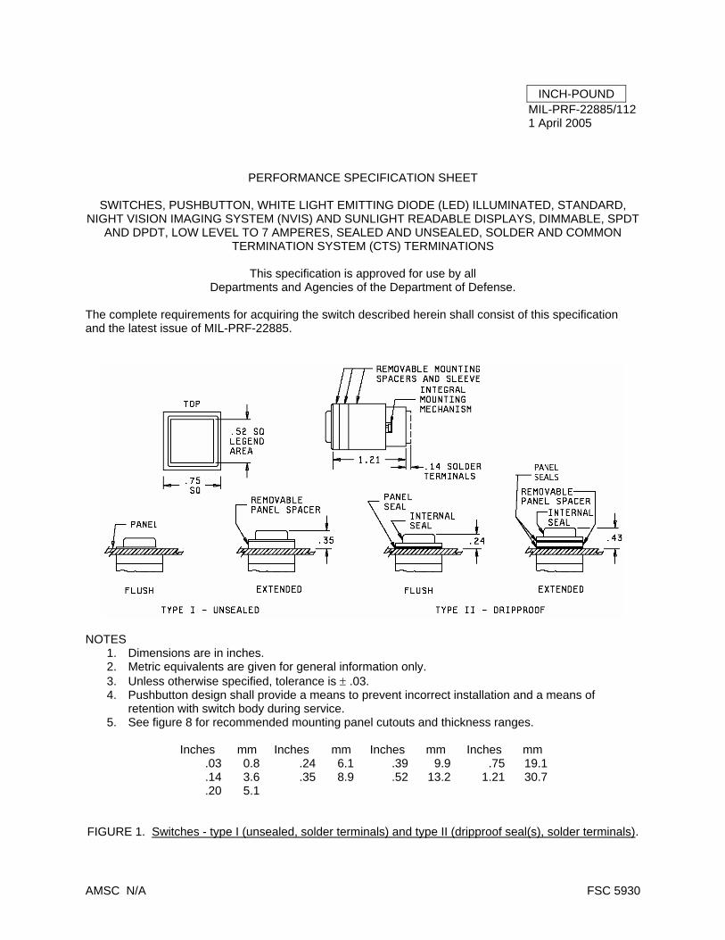
FIGURE 2. Switches - type III (watertight and splashproof seal, solder terminals).
MIL-PRF-22885/112
3
Contact Part Number Dimension A (inches)
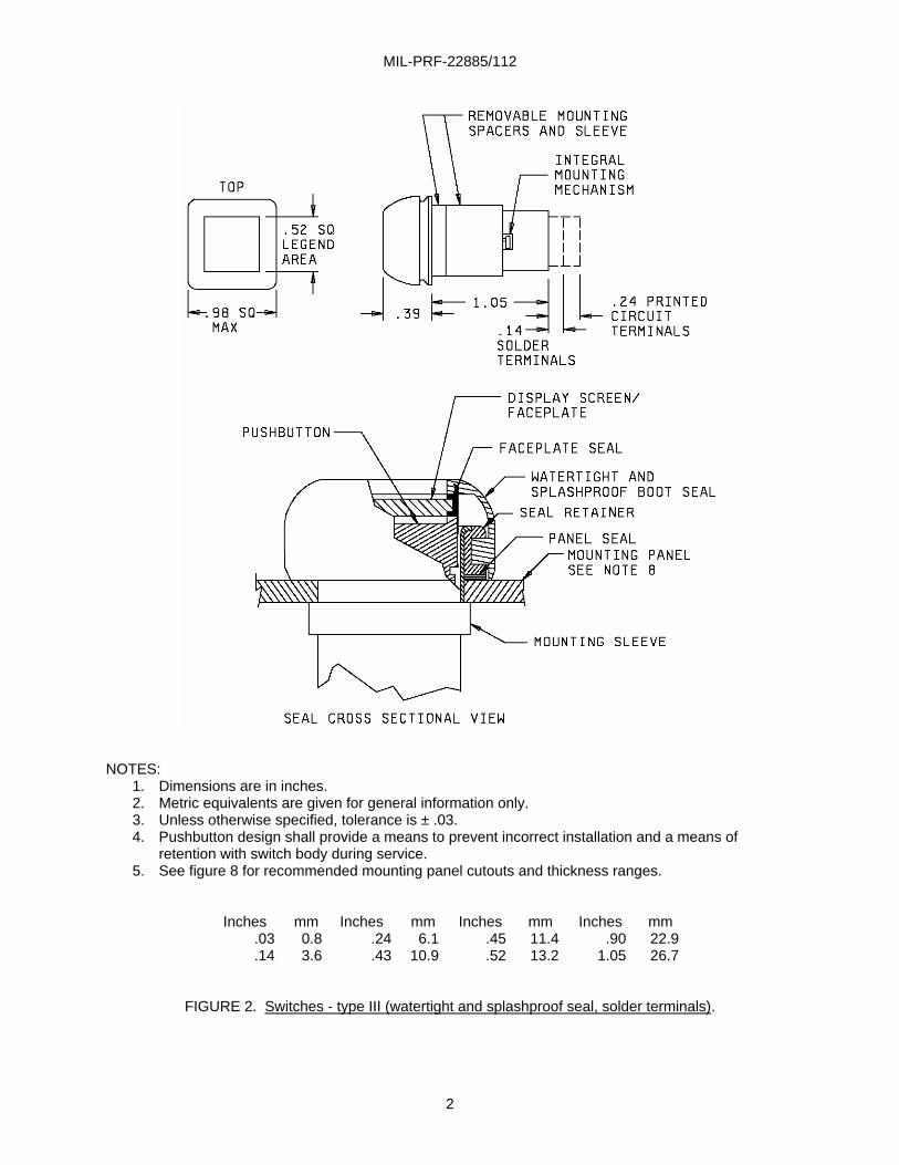
M39029/22-192 1.46 M39029/16-168 1.59
NOTES:
1. Dimensions are in inches. 2. Metric equivalents are given for general information only. 3. Unless otherwise specified, tolerance is ± .03. 4. Pushbutton design shall provide a means to prevent incorrect installation and a means of
retention with switch body during service. 5. The CTS receptacle assembly shall be removable from switch module and switch housing unit
assembly. 6. The switch module is an integral part of the switch housings and CTS unit assembly. 7. The CTS pins shall be M39029/22-192 or M39029/16-168 and shall be removable from the CTS
module assembly. The CTS pins accept 20, 22, or 24 gauge wire. 8. See figure 8 for recommended mounting panel cutouts and thickness ranges.
Inches
.20
.24
.35
mm 5.1 6.1 8.9
Inches .43 .44
mm 10.911.2
Inches .52 .75
mm 13.219.1
Inches 1.46 1.59
mm 37.1 40.4
FIGURE 3. Switches, common termination system - type IV (unsealed) and type V (dripproof seal(s)).
MIL-PRF-22885/112
4
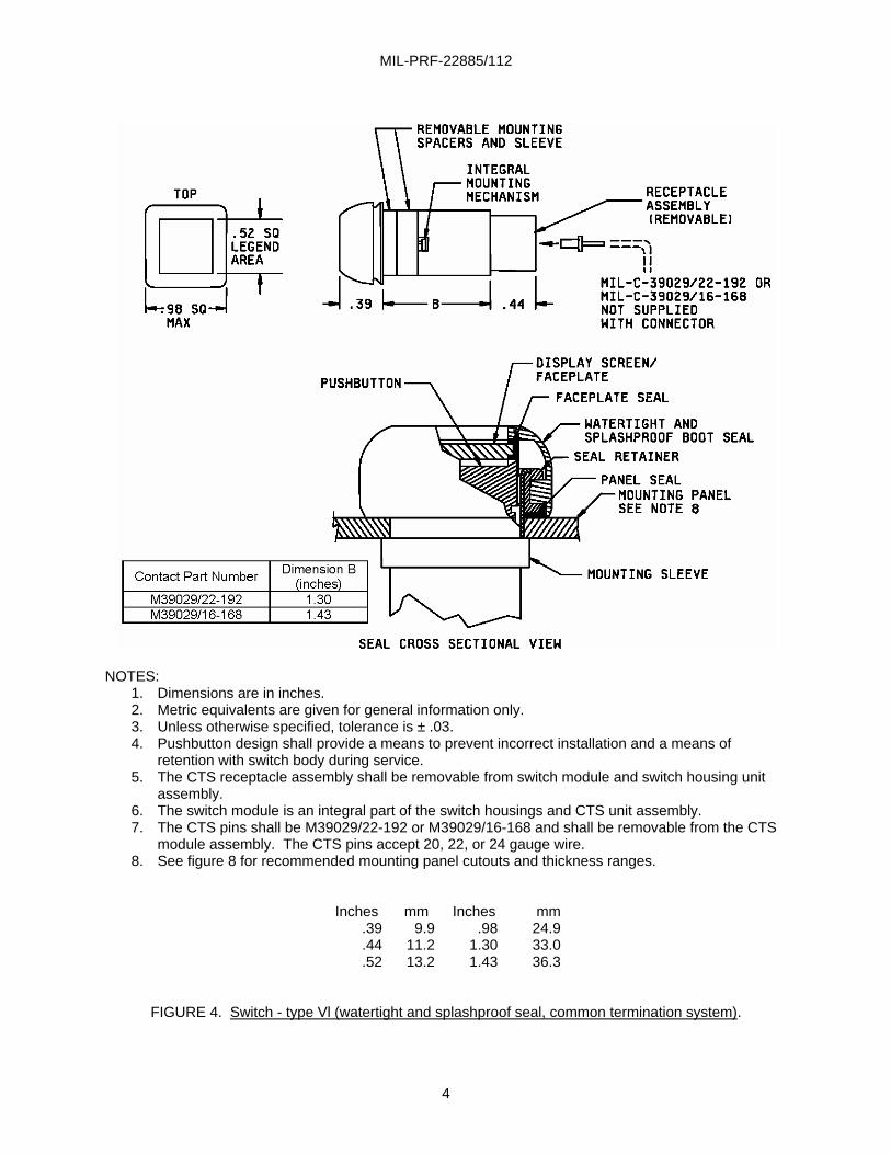
NOTES:
1. Dimensions are in inches. 2. Metric equivalents are given for general information only. 3. Unless otherwise specified, tolerance is ± .03. 4. Pushbutton design shall provide a means to prevent incorrect installation and a means of
retention with switch body during service. 5. The CTS receptacle assembly shall be removable from switch module and switch housing unit
assembly. 6. The switch module is an integral part of the switch housings and CTS unit assembly. 7. The CTS pins shall be M39029/22-192 or M39029/16-168 and shall be removable from the CTS
module assembly. The CTS pins accept 20, 22, or 24 gauge wire. 8. See figure 8 for recommended mounting panel cutouts and thickness ranges.
Inches .39 .44 .52
mm 9.9
11.2 13.2
Inches .98
1.30 1.43
mm 24.9 33.0 36.3
FIGURE 4. Switch - type Vl (watertight and splashproof seal, common termination system).
MIL-PRF-22885/112
5
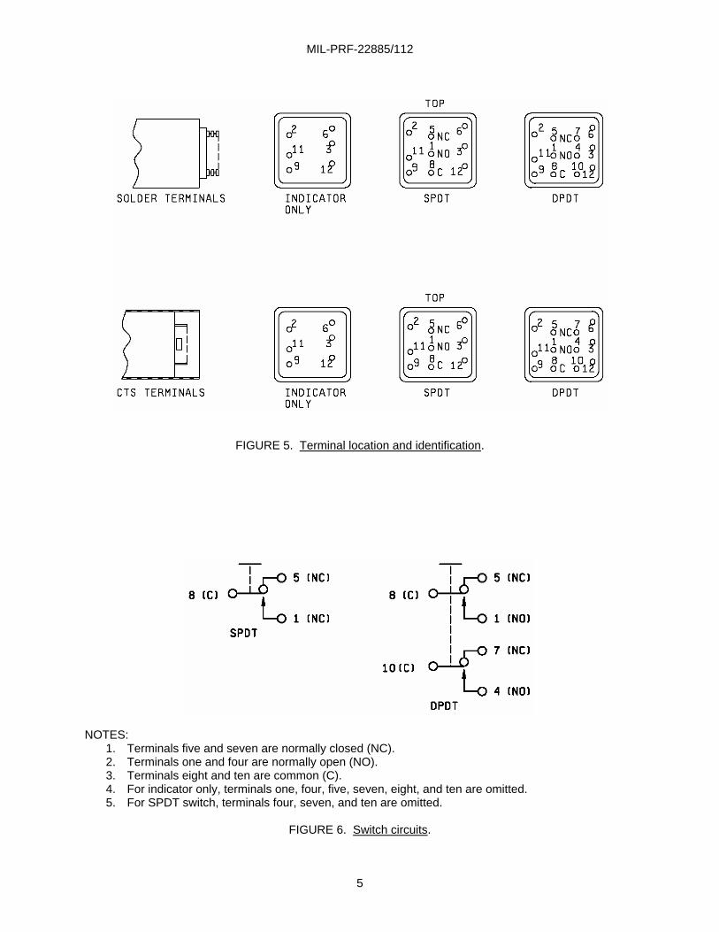
FIGURE 5. Terminal location and identification.
NOTES:
1. Terminals five and seven are normally closed (NC). 2. Terminals one and four are normally open (NO). 3. Terminals eight and ten are common (C). 4. For indicator only, terminals one, four, five, seven, eight, and ten are omitted. 5. For SPDT switch, terminals four, seven, and ten are omitted.
FIGURE 6. Switch circuits.
MIL-PRF-22885/112
6
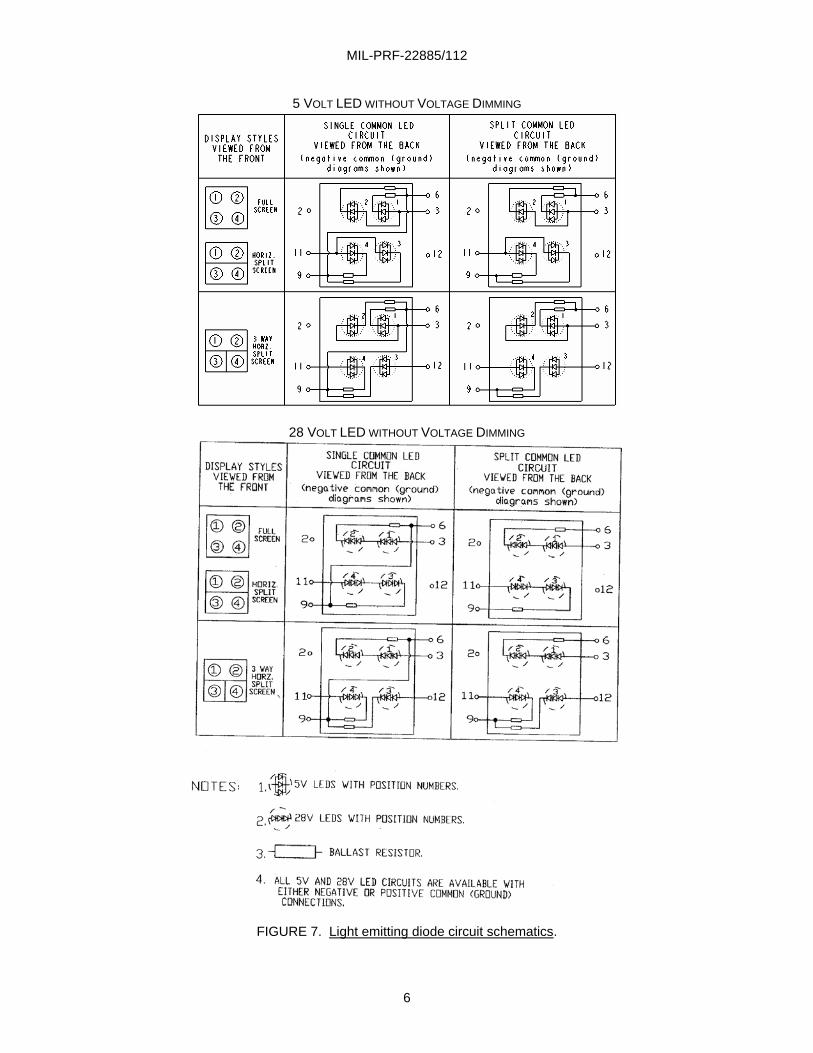
5 VOLT LED WITHOUT VOLTAGE DIMMING
28 VOLT LED WITHOUT VOLTAGE DIMMING
FIGURE 7. Light emitting diode circuit schematics.
MIL-PRF-22885/112
7
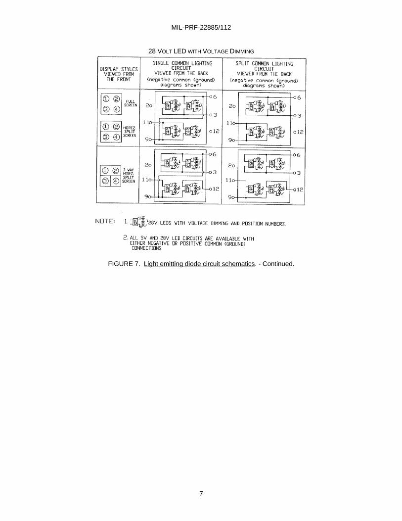
28 VOLT LED WITH VOLTAGE DIMMING
FIGURE 7. Light emitting diode circuit schematics. - Continued.
MIL-PRF-22885/112
8
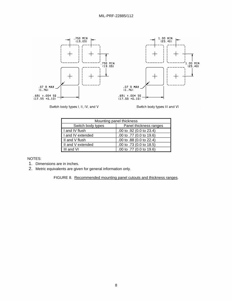
Mounting panel thickness Switch body types Panel thickness ranges
I and IV flush .00 to .92 (0.0 to 23.4) I and IV extended .00 to .77 (0.0 to 19.6) II and V flush .00 to .88 (0.0 to 22.4) II and V extended .00 to .73 (0.0 to 18.5) III and VI .00 to .77 (0.0 to 19.6)
NOTES: 1. Dimensions are in inches. 2. Metric equivalents are given for general information only.
FIGURE 8. Recommended mounting panel cutouts and thickness ranges.
MIL-PRF-22885/112
9
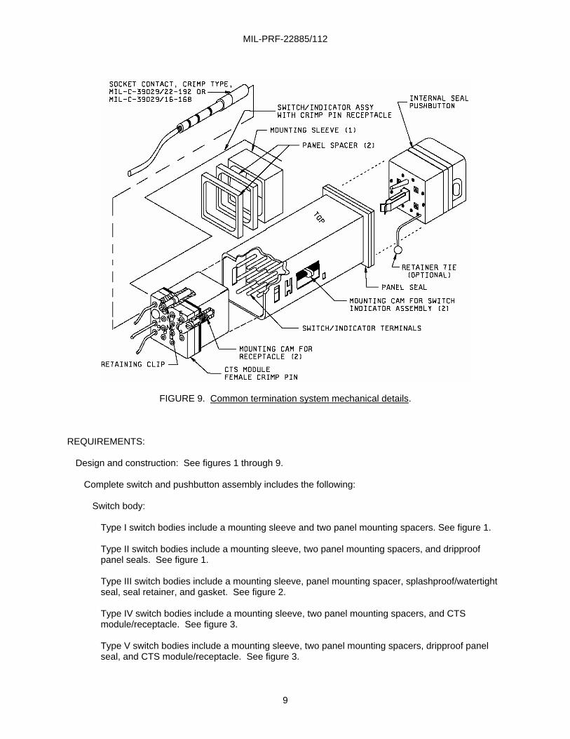
FIGURE 9. Common termination system mechanical details.
REQUIREMENTS:
Design and construction: See figures 1 through 9. Complete switch and pushbutton assembly includes the following:
Switch body:
Type I switch bodies include a mounting sleeve and two panel mounting spacers. See figure 1. Type II switch bodies include a mounting sleeve, two panel mounting spacers, and dripproof panel seals. See figure 1. Type III switch bodies include a mounting sleeve, panel mounting spacer, splashproof/watertight seal, seal retainer, and gasket. See figure 2.
Type IV switch bodies include a mounting sleeve, two panel mounting spacers, and CTS module/receptacle. See figure 3. Type V switch bodies include a mounting sleeve, two panel mounting spacers, dripproof panel seal, and CTS module/receptacle. See figure 3.
MIL-PRF-22885/112
10
Type Vl switch bodies include a mounting sleeve, panel mounting spacer, splashproof/watertight seal, seal retainer, gasket, and CTS module/receptacle. See figure 4.
Pushbutton: All pushbutton assemblies include a display faceplate and legend assembly, display segment divider, replaceable LED light source assembly, pushbutton faceplate seal, retainer/ bezel, and optional captive pushbutton retainer.
Other parts, when applicable, are NVIS compatible filters, EMI/RFI shielding, and dripproof or splashproof/watertight seals. Enclosure designs:
Symbol Switch type
1 (unsealed)……………………….. 1 and IV 2 (dripproof)……………………….. II and V 3 (watertight) and 4 (splashproof). III and Vl
Temperature characteristic: Symbol 1 (-55 °C to +85 °C). Vibration grade: Symbol 3 (10 to 2,000 Hz, 15 g peak). Operation:
Symbol A (momentary action switch). Symbol B (alternate action switch). Symbol H (indicator light).
Display types:
N - Legend is white on nonreflective matte black background when LED is not lighted. Legend is colored on black background when LED is lighted. W - Legend is opaque black on white background when LED is not lighted. Legend is opaque black on colored background when LED is lighted. S - Sunlight readable contrast requirements apply. Background is nonreflective matte black. Legend is not visible when LED is not lighted. Legend appears in color on black background when LED is lighted.
Material:
Finish: When used, shall be selected to enable the switch to meet performance requirements of this specification. It may be Aluminum alloy black anodized per MIL-A-8625, Type II, Class 2, or chemical filmed per MIL-C-5541, Class 3.
Operating characteristics:
Actuating force: 5 pounds (22.2 N) max. Plunger travel: .130 ± .030. Pushbutton removal force: 2 to 5 pounds (8.9 N to 22.2 N). Not applicable to type III or type Vl (sealed) switches.
MIL-PRF-22885/112
11
Shock:
All switch types: Method I (75 g). Switch types III and Vl (sealed switches): High impact shock in accordance with MIL-S-901, grade A, class II (for deck-mounted equipment) when attached to the anvil plate of the shock machine by means of standard mounting (figure 11-C) with simulated console, which provides resilient mounting typical of in-service use within ”deck-mounted” electronic cabinets or panels. These units are not recommended for direct ”hull mounted” applications.
Salt spray: Test condition A (96 hours).
Sand and dust: Applicable. Terminal strength:
Solder terminals, applied force and direction of force: 3 pounds perpendicular to the long axis, and 5 pounds parallel to the long axis.
Electrical endurance: 25,000 cycles at the following electrical ratings:
Silver contacts: Sea level 50,000 feet
28 V dc:
Resistive 7.0 A 4.0 A Inductive 4.0 A 2.5 A Lamp 2.5 A 2.5 A
115 V ac, 60 Hz:
Resistive 7.0 A Inductive 7.0 A Lamp 2.0 A
Gold plated contacts:
28 V dc:
Resistive 1.0 A Inductive. 0.5 A
Low-level life: Applicable to switches with gold plated contacts.
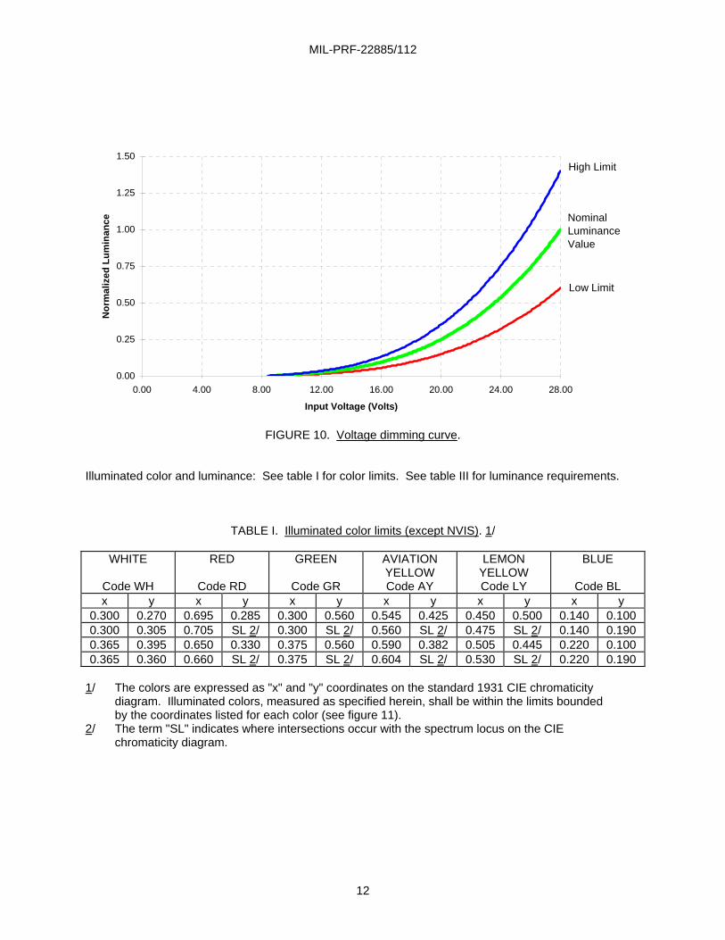
Intermediate current: Applicable to switches with silver contacts. Mechanical endurance: 100,000 cycles consisting of 5,000 cycles of operation at -55°C ± 2°C, 10,000 cycles of operation at +85°C ± 2°C, and 85,000 cycles of operation at room temperature. Voltage Dimming Control: Applicable to 28 VDC lighting circuits with dimming devices only. These control circuits allow to adjust LED pushbutton display brightness with variable voltage, similar to displays with incandescent lamps. The Nominal Dimming Curve with high and low limits is shown in figure 10. It starts at about 8.4 V where LED current is approximately 0.002 mA and continues to 28 V where current reaches 20 mA ± 2 mA. Note, that display brightness (luminance) is directly proportional to LED current.
MIL-PRF-22885/112
12
0.00
0.25
0.50
0.75
1.00
1.25
1.50
0.00 4.00 8.00 12.00 16.00 20.00 24.00 28.00
Input Voltage (Volts)
Nor
mal
ized
Lum
inan
ce
High Limit
Low Limit
NominalLuminanceValue
FIGURE 10. Voltage dimming curve.
Illuminated color and luminance: See table I for color limits. See table III for luminance requirements.
TABLE I. Illuminated color limits (except NVIS). 1/
WHITE
Code WH
RED
Code RD
GREEN
Code GR
AVIATION YELLOW Code AY
LEMON YELLOW Code LY
BLUE
Code BL x y x y x y x y x y x y
0.300 0.270 0.695 0.285 0.300 0.560 0.545 0.425 0.450 0.500 0.140 0.100 0.300 0.305 0.705 SL 2/ 0.300 SL 2/ 0.560 SL 2/ 0.475 SL 2/ 0.140 0.190 0.365 0.395 0.650 0.330 0.375 0.560 0.590 0.382 0.505 0.445 0.220 0.100 0.365 0.360 0.660 SL 2/ 0.375 SL 2/ 0.604 SL 2/ 0.530 SL 2/ 0.220 0.190
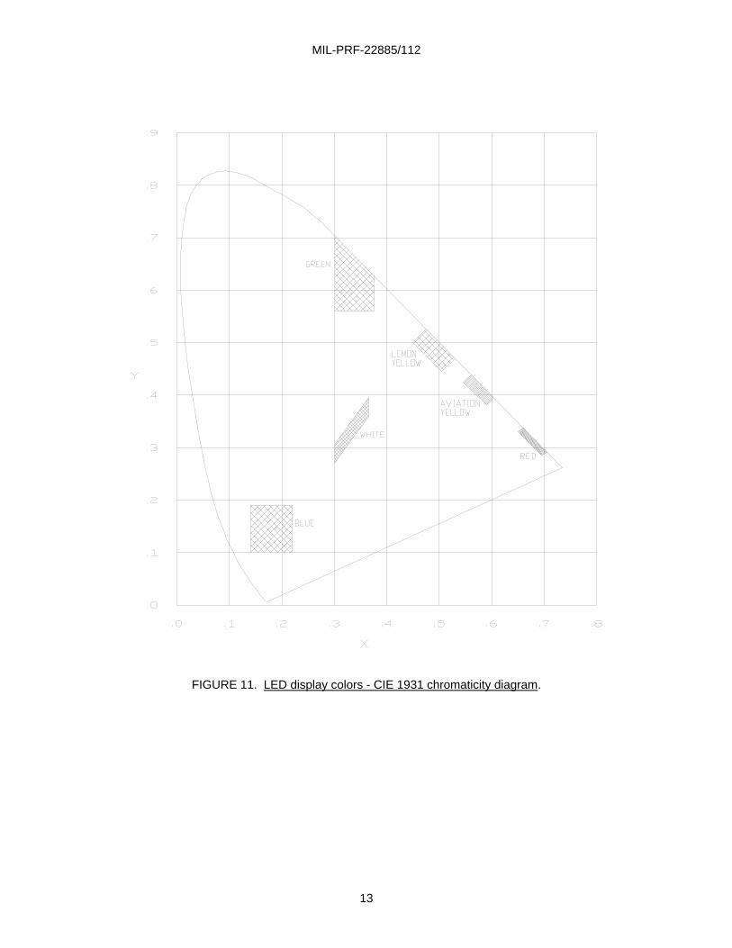
1/ The colors are expressed as "x" and "y" coordinates on the standard 1931 CIE chromaticity
diagram. Illuminated colors, measured as specified herein, shall be within the limits bounded by the coordinates listed for each color (see figure 11).
2/ The term "SL" indicates where intersections occur with the spectrum locus on the CIE chromaticity diagram.
MIL-PRF-22885/112
13
FIGURE 11. LED display colors - CIE 1931 chromaticity diagram.
MIL-PRF-22885/112
14
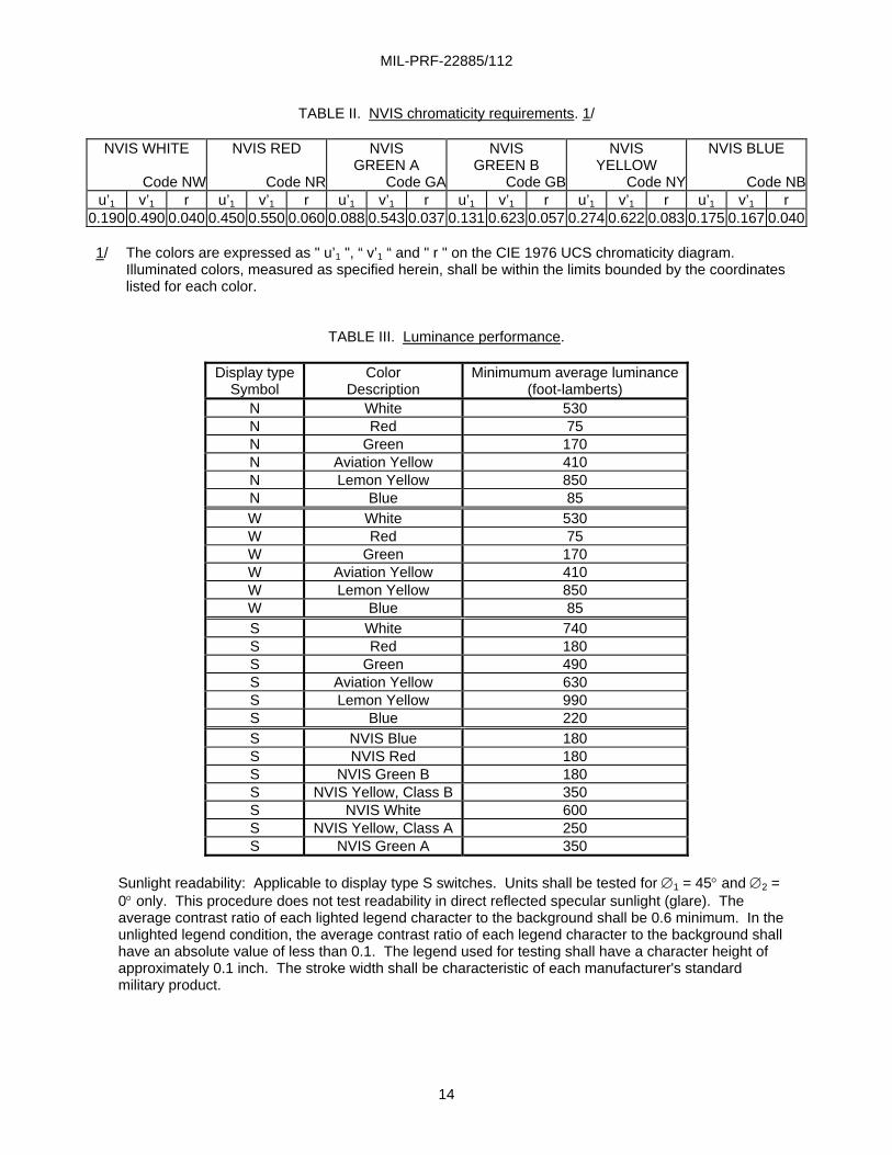
TABLE II. NVIS chromaticity requirements. 1/ NVIS WHITE
Code NW
NVIS RED
Code NR
NVIS GREEN A
Code GA
NVIS GREEN B
Code GB
NVIS YELLOW
Code NY
NVIS BLUE
Code NBu’1 v’1 r u’1 v’1 r u’1 v’1 r u’1 v’1 r u’1 v’1 r u’1 v’1 r
0.190 0.490 0.040 0.450 0.550 0.060 0.088 0.543 0.037 0.131 0.623 0.057 0.274 0.622 0.083 0.175 0.167 0.040
1/ The colors are expressed as " u’1 ", “ v’1 “ and " r " on the CIE 1976 UCS chromaticity diagram. Illuminated colors, measured as specified herein, shall be within the limits bounded by the coordinates listed for each color.
TABLE III. Luminance performance.
Display type Symbol
Color Description
Minimumum average luminance (foot-lamberts)
N White 530 N Red 75 N Green 170 N Aviation Yellow 410 N Lemon Yellow 850 N Blue 85 W White 530 W Red 75 W Green 170 W Aviation Yellow 410 W Lemon Yellow 850 W Blue 85 S White 740 S Red 180 S Green 490 S Aviation Yellow 630 S Lemon Yellow 990 S Blue 220 S NVIS Blue 180 S NVIS Red 180 S NVIS Green B 180 S NVIS Yellow, Class B 350 S NVIS White 600 S NVIS Yellow, Class A 250 S NVIS Green A 350
Sunlight readability: Applicable to display type S switches. Units shall be tested for ∅1 = 45° and ∅2 = 0° only. This procedure does not test readability in direct reflected specular sunlight (glare). The average contrast ratio of each lighted legend character to the background shall be 0.6 minimum. In the unlighted legend condition, the average contrast ratio of each legend character to the background shall have an absolute value of less than 0.1. The legend used for testing shall have a character height of approximately 0.1 inch. The stroke width shall be characteristic of each manufacturer's standard military product.
MIL-PRF-22885/112
15
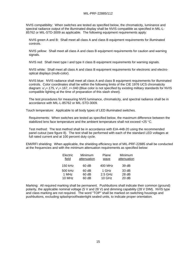
NVIS compatibility: When switches are tested as specified below, the chromaticity, luminance and spectral radiance output of the illuminated display shall be NVIS compatible as specified in MIL-L-85762 or MIL-STD-3009 as applicable. The following equipment requirements apply:
NVIS green A and B: Shall meet all class A and class B equipment requirements for illuminated controls. NVIS yellow: Shall meet all class A and class B equipment requirements for caution and warning signals. NVIS red: Shall meet type I and type II class B equipment requirements for warning signals. NVIS white: Shall meet all class A and class B equipment requirements for electronic and electro-optical displays (multi-color).
NVIS blue: NVIS radiance shall meet all class A and class B equipment requirements for illuminated controls. Color coordinates shall be within the following limits of the CIE 1976 UCS chromaticity diagram: u’1=.175, v’1=.167, r=.040 (Blue color is not specified by existing military standards for NVIS compatible lighting at the time of preparation of this slash sheet). The test procedures for measuring NVIS luminance, chromaticity, and spectral radiance shall be in accordance with MIL-L-85762 or MIL-STD-3009.
Touch temperature: Applicable to all body types of LED illuminated switches.
Requirements: When switches are tested as specified below, the maximum difference between the stabilized lens face temperature and the ambient temperature shall not exceed +25 °C. Test method: The test method shall be in accordance with EIA-448-20 using the recommended panel cutout (see figure 8). The test shall be performed with each of the standard LED voltages at full rated current and at 100 percent duty cycle.
EMI/RFI shielding: When applicable, the shielding efficiency test of MIL-PRF-22885 shall be conducted at the frequencies and with the minimum attenuation requirements as specified below:
Electric Minimum Plane Minimum
field attenuation wave attenuation
150 kHz 60 dB 400 MHz 39 dB 500 kHz 60 dB 1 GHz 33 dB 1 MHz 60 dB 2.5 GHz 28 dB
10 MHz 60 dB 10 GHz 20 dB
Marking: All required marking shall be permanent. Pushbuttons shall indicate their common (ground) polarity, the applicable nominal voltage (5 V and 28 V) and dimming capability (28 V DIM). NVIS type and class marking are not required. The word "TOP" shall be marked on switching housings and pushbuttons, excluding splashproof/watertight sealed units, to indicate proper orientation.
MIL-PRF-22885/112
16
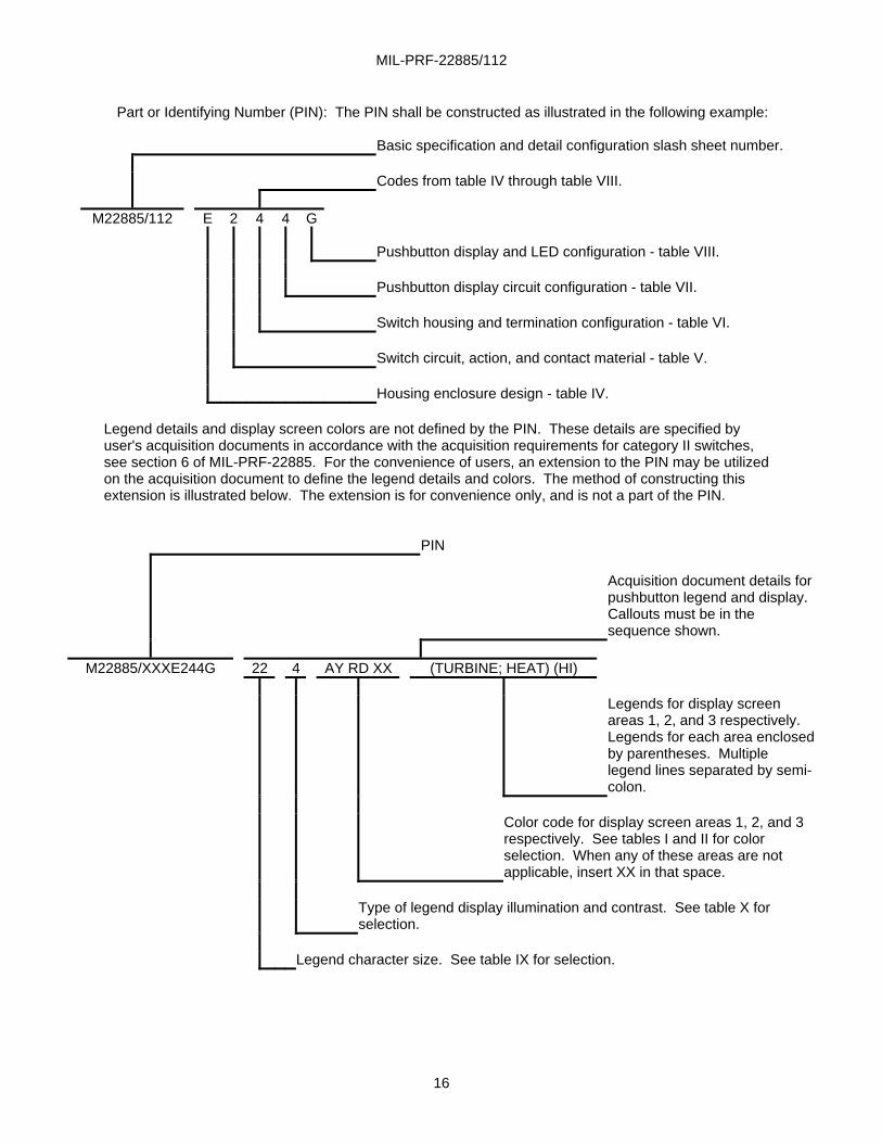
Part or Identifying Number (PIN): The PIN shall be constructed as illustrated in the following example: Basic specification and detail configuration slash sheet number. Codes from table IV through table VIII.
M22885/112 E 2 4 4 G Pushbutton display and LED configuration - table VIII. Pushbutton display circuit configuration - table VII. Switch housing and termination configuration - table VI. Switch circuit, action, and contact material - table V. Housing enclosure design - table IV.
Legend details and display screen colors are not defined by the PIN. These details are specified by user's acquisition documents in accordance with the acquisition requirements for category II switches, see section 6 of MIL-PRF-22885. For the convenience of users, an extension to the PIN may be utilized on the acquisition document to define the legend details and colors. The method of constructing this extension is illustrated below. The extension is for convenience only, and is not a part of the PIN. PIN Acquisition document details for
pushbutton legend and display. Callouts must be in the sequence shown.
M22885/XXXE244G 22 4 AY RD XX (TURBINE; HEAT) (HI)
Legends for display screen
areas 1, 2, and 3 respectively. Legends for each area enclosed by parentheses. Multiple legend lines separated by semi-colon.
Color code for display screen areas 1, 2, and 3
respectively. See tables I and II for color selection. When any of these areas are not applicable, insert XX in that space.
Type of legend display illumination and contrast. See table X for
selection. Legend character size. See table IX for selection.
MIL-PRF-22885/112
17
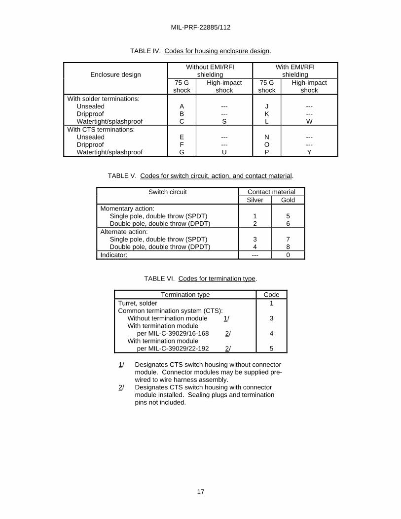
TABLE IV. Codes for housing enclosure design.
Enclosure design
Without EMI/RFI shielding
With EMI/RFI shielding
75 G shock
High-impact shock
75 G shock
High-impact shock
With solder terminations: Unsealed Dripproof Watertight/splashproof
A B C
--- --- S
J K L
--- --- W
With CTS terminations: Unsealed Dripproof Watertight/splashproof
E F G
--- --- U
N O P
--- --- Y
TABLE V. Codes for switch circuit, action, and contact material.
Switch circuit Contact material Silver Gold
Momentary action: Single pole, double throw (SPDT) Double pole, double throw (DPDT)
1 2
5 6
Alternate action: Single pole, double throw (SPDT) Double pole, double throw (DPDT)
3 4
7 8
Indicator: --- 0
TABLE VI. Codes for termination type.
Termination type Code Turret, solder Common termination system (CTS):
Without termination module 1/ With termination module
per MIL-C-39029/16-168 2/ With termination module
per MIL-C-39029/22-192 2/
1
3
4
5
1/ Designates CTS switch housing without connector module. Connector modules may be supplied pre-wired to wire harness assembly.
2/ Designates CTS switch housing with connector module installed. Sealing plugs and termination pins not included.
MIL-PRF-22885/112
18
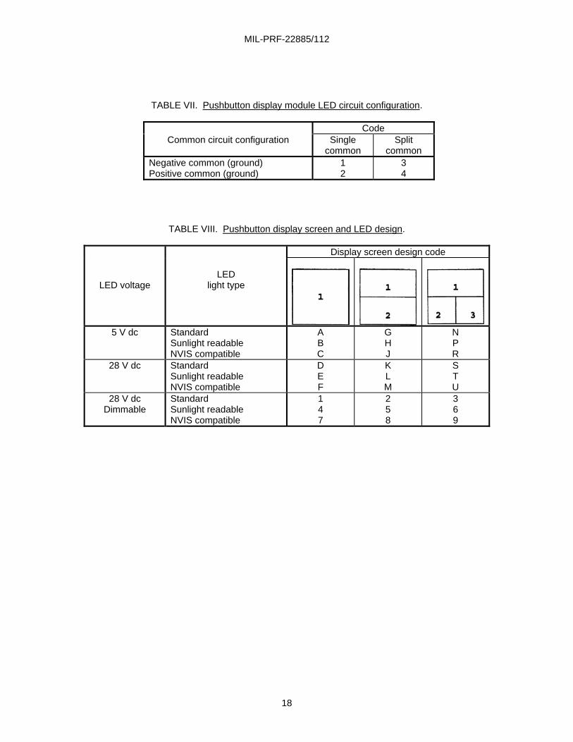
TABLE VII. Pushbutton display module LED circuit configuration.
Code Common circuit configuration Single
common Split
common Negative common (ground) Positive common (ground)
1 2
3 4
TABLE VIII. Pushbutton display screen and LED design.
Display screen design code
LED voltage
LED
light type
5 V dc Standard Sunlight readable NVIS compatible
A B C
G H J
N P R
28 V dc Standard Sunlight readable NVIS compatible
D E F
K L M
S T U
28 V dc Dimmable
Standard Sunlight readable NVIS compatible
1 4 7
2 5 8
3 6 9
MIL-PRF-22885/112
19
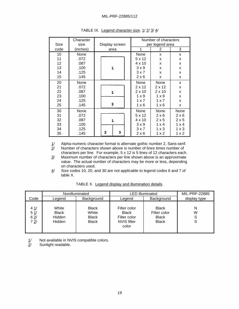
TABLE IX. Legend character size. 1/ 2/ 3/ 4/
Size
Character size
Display screen
Number of characters per legend area
code (inches) area 1 2 3 10 11 12 13 14 15
None .072 .087 .100 .125 .145
None 5 x 12 4 x 10 3 x 9 3 x 7 2 x 6
x x x x x x
x x x x x x
20 21 22 23 24 25
None .072 .087 .100 .125 .145
None 2 x 12 2 x 10 1 x 9 1 x 7 1 x 6
None 2 x 12 2 x 10 1 x 9 1 x 7 1 x 6
x x x x x x
30 31 32 33 34 35
None .072 .087 .100 .125 .145
None 5 x 12 4 x 10 3 x 9 3 x 7 2 x 6
None 2 x 6 2 x 5 1 x 4 1 x 3 1 x 2
None 2 x 6 2 x 5 1 x 4 1 x 3 1 x 2
1/ Alpha-numeric character format is alternate gothic number 2, Sans-serif. 2/ Number of characters shown above is number of lines times number of
characters per line. For example, 5 x 12 is 5 lines of 12 characters each. 3/ Maximum number of characters per line shown above is an approximate
value. The actual number of characters may be more or less, depending on characters used.
4/ Size codes 10, 20, and 30 are not applicable to legend codes 6 and 7 of table X.
TABLE X. Legend display and illumination details.
Nonilluminated LED illuminated MIL-PRF-22885
Code Legend Background Legend Background display type
4 1/ 5 1/ 6 2/ 7 2/
White Black
Hidden Hidden
Black White Black Black
Filter color
Black Filter color NVIS filter
color
Black
Filter color Black Black
N W S S
1/ Not available in NVIS compatible colors. 2/ Sunlight readable.
MIL-PRF-22885/112
20
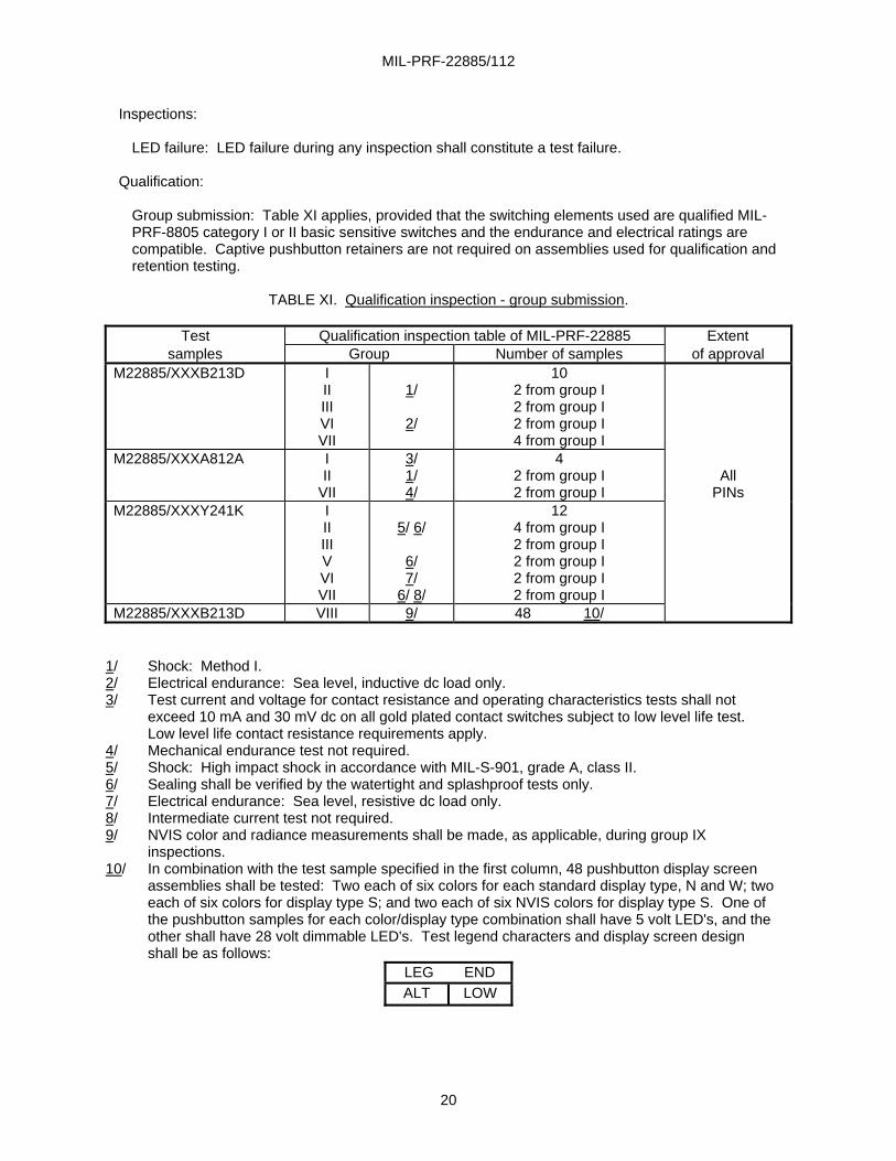
Inspections:
LED failure: LED failure during any inspection shall constitute a test failure.
Qualification:
Group submission: Table XI applies, provided that the switching elements used are qualified MIL-PRF-8805 category I or II basic sensitive switches and the endurance and electrical ratings are compatible. Captive pushbutton retainers are not required on assemblies used for qualification and retention testing.
TABLE XI. Qualification inspection - group submission.
Test Qualification inspection table of MIL-PRF-22885 Extent
samples Group Number of samples of approval M22885/XXXB213D I
II III VI VII
1/
2/
10 2 from group I 2 from group I 2 from group I 4 from group I
M22885/XXXA812A I II
VII
3/ 1/ 4/
4 2 from group I 2 from group I
All
PINs M22885/XXXY241K I
II III V VI VII
5/ 6/
6/ 7/
6/ 8/
12 4 from group I 2 from group I 2 from group I 2 from group I 2 from group I
M22885/XXXB213D VIII 9/ 48 10/ 1/ Shock: Method I. 2/ Electrical endurance: Sea level, inductive dc load only. 3/ Test current and voltage for contact resistance and operating characteristics tests shall not
exceed 10 mA and 30 mV dc on all gold plated contact switches subject to low level life test. Low level life contact resistance requirements apply.
4/ Mechanical endurance test not required. 5/ Shock: High impact shock in accordance with MIL-S-901, grade A, class II. 6/ Sealing shall be verified by the watertight and splashproof tests only. 7/ Electrical endurance: Sea level, resistive dc load only. 8/ Intermediate current test not required. 9/ NVIS color and radiance measurements shall be made, as applicable, during group IX
inspections. 10/ In combination with the test sample specified in the first column, 48 pushbutton display screen
assemblies shall be tested: Two each of six colors for each standard display type, N and W; two each of six colors for display type S; and two each of six NVIS colors for display type S. One of the pushbutton samples for each color/display type combination shall have 5 volt LED's, and the other shall have 28 volt dimmable LED's. Test legend characters and display screen design shall be as follows:
LEG END ALT LOW
MIL-PRF-22885/112
21
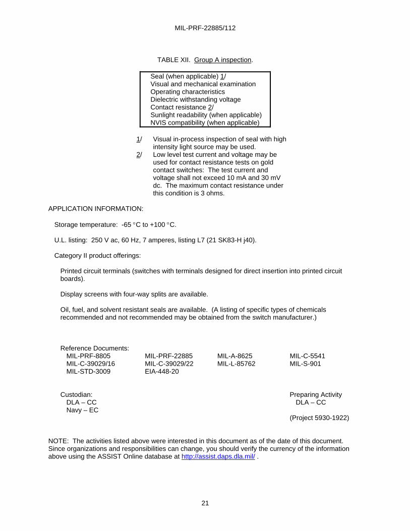
TABLE XII. Group A inspection.
Seal (when applicable) 1/ Visual and mechanical examination Operating characteristics Dielectric withstanding voltage Contact resistance 2/ Sunlight readability (when applicable) NVIS compatibility (when applicable)
1/ Visual in-process inspection of seal with high
intensity light source may be used. 2/ Low level test current and voltage may be
used for contact resistance tests on gold contact switches: The test current and voltage shall not exceed 10 mA and 30 mV dc. The maximum contact resistance under this condition is 3 ohms.
APPLICATION INFORMATION:
Storage temperature: -65 °C to +100 °C. U.L. listing: 250 V ac, 60 Hz, 7 amperes, listing L7 (21 SK83-H j40). Category II product offerings:
Printed circuit terminals (switches with terminals designed for direct insertion into printed circuit boards). Display screens with four-way splits are available. Oil, fuel, and solvent resistant seals are available. (A listing of specific types of chemicals recommended and not recommended may be obtained from the switch manufacturer.) Reference Documents: MIL-PRF-8805 MIL-PRF-22885 MIL-A-8625 MIL-C-5541 MIL-C-39029/16 MIL-C-39029/22 MIL-L-85762 MIL-S-901 MIL-STD-3009 EIA-448-20 Custodian: Preparing Activity DLA – CC DLA – CC Navy – EC (Project 5930-1922)
NOTE: The activities listed above were interested in this document as of the date of this document. Since organizations and responsibilities can change, you should verify the currency of the information above using the ASSIST Online database at http://assist.daps.dla.mil/ .