IN - United States Navytycho.usno.navy.mil/ptti/1973papers/Vol 05_08.pdf · technique, the...
19
PKECISE TIMING CORRELATION IN TELEMETRY RECORDING AND PROCESSING SYSTEMS R. B. Pickett F. L. Matthews ITT Fcdcral Electric Corporation Vandenberg Air Force Hasc Indcpentlent PCM telemetry tlttta signals received from missiles must be corre- lated to within 5100 microseconds for comparison with radar clata. 'rests have been conducted at the Space and Missile Test Center (SAMTEC), Vandenberg Air Force Base, California, to determine RF antenna receiving system delays; de- lays associated with widcbmd :malog tape recorders used in the recording, dub- bing and repdocuing processes; and uncertainties associated with computer pro- cessed time tag data. Several rnethocls user1 in the recording of timeing arc evaluated. Timing error vcrsus tape recorder head alignment is plotted. Tape recorder phase lead effects on time code forrnztts and data are given. The time bias associated with computers processing of data js presented. Sources of tim- ing errors md the calibration :mtl operating techniques available to minimize these errors arc discussed. Through the application of a special time tagging technique, the cumulative timing bias from :ill sources is dctcrrnineti and the bias removed from final data. Conclusions from test d:~t:i show that relative time differences in receiving, recording, playbaclc :md processing of two telemetry links c,m be accomplished with a t4 microseconds accuracy. In :ttltlition, the absolute time tag error (with respect to IYSC) can be reducer1 to less than 15 y scc. This investigation is believed to be the first attempt to identify the individu:tl error contributions within ihc telemetry system and to describe the lnethorls of error reduction and correction. INTRODUCTION Missiles launched from Vandenburg Air Force Ease in California arc tracked by systems located throughout thf world. Rxdars provide position nnd velocity data in terms of range, azimuth, elevation and range rate. Telemetry stations receive information encoded and trnnsmittecl from t h ~ missile. For lnissiles configured with inertial p i d a n c ~ systcms, position and velocity information in terms of X, Y, Z and X, Y, ? is tr:tnsrnitted on thc telemetry link. The continued improvement in ballistic missile performance places an ever in- creasing accuracy requircm ent on position and velocity data. When sensor
Transcript of IN - United States Navytycho.usno.navy.mil/ptti/1973papers/Vol 05_08.pdf · technique, the...
PKECISE TIMING CORRELATION IN TELEMETRY RECORDING AND PROCESSING SYSTEMS
R. B. Pickett F. L. Matthews
ITT Fcdcral Electric Corporation Vandenberg Air Force Hasc
Indcpentlent PCM telemetry tlttta signals received from missi les must be corre- lated to within 5100 microseconds for comparison with radar clata. ' rests have been conducted a t the Space and Missile Tes t Center (SAMTEC), Vandenberg Air Force Base, California, to determine RF antenna receiving system delays; de- lays associated with widcbmd :malog tape recorders used in the recording, dub- bing and repdocuing processes; and uncertainties associated with computer pro- cessed time tag data. Several rnethocls user1 in the recording of timeing a r c evaluated. Timing e r r o r vcrsus tape recorder head alignment i s plotted. Tape recorder phase lead effects on time code forrnztts and data a r e given. The time bias associated with computers processing of data js presented. Sources of tim- ing e r r o r s md the calibration :mtl operating techniques available to minimize these e r r o r s a r c discussed. Through the application of a special time tagging technique, the cumulative timing bias from :ill sources is dctcrrnineti and the bias removed from final data. Conclusions from test d:~t:i show that relative time differences in receiving, recording, playbaclc :md processing of two telemetry links c,m be accomplished with a t 4 microseconds accuracy. In :ttltlition, the absolute time tag e r r o r (with respect to IYSC) can be reducer1 to less than 15 y scc. This investigation i s believed t o be the f i r s t attempt to identify the individu:tl e r r o r contributions within ihc telemetry system and to describe the lnethorls of e r r o r reduction and correction.
INTRODUCTION
Missiles launched from Vandenburg Air Force Ease in California a r c tracked by systems located throughout thf world. Rxdars provide position nnd velocity data in te rms of range, azimuth, elevation and range rate. Telemetry stations receive information encoded and trnnsmittecl from t h ~ missile. For lnissiles configured with inertial p i d a n c ~ systcms, position and velocity information in t e rms of X, Y, Z and X, Y , ? is tr:tnsrnitted on thc telemetry link.
The continued improvement in ballistic missile performance places a n ever in- creasing accuracy requircm ent on position and velocity data. When sensor
performance capabilitics do not meet the accuracy recluircmcnts directly, analysts use multistation solutions to refine the trajectory data. Such solutions may include inputs from widely spaced radars as well a s thc inertial guidance data. When merging the sources, timing offsets a r e particularly troublesome, a s such e r ro r s propxgatc in a complex manner during the merging.
In order to avoid these pmblems, timing offsets a r c limited to +I00 micro- seconds ( p s) o r less. This reduces the position e r ro r due to timing alone to less than 2.4 fcct, even at escape velocity. In practical tcrrns, this means that data received at stations throughout the world must be synchronized to
1 within +I00 p s of UTC.
Range Timing System
The SAMTEC timing system accuracy is directly traceablc to the U. S. Naval Observatory's Coordinatcd Universal Time (UTC). This traceability i s mxin- tainod a s shown in Figure 1 through the SAMTEC Precision Mcxsurement Laboratories (PML) Prccise Time Reference Statjon (PTRS). The I'ML main- tains x calibration accuracy of 12.0 ps of epoch USNO-UTC master clock. The P M L has the responsibility to maintain the four SAMTEC Central Time Signal Generators (CTSG) Cesium Heam primary frequency and clock standards in calibration and synchronization with Ul'C (USNO). The CTSG systems a r e in- stalled a t Vandenberg Air Force Base and Pillar Point Air Forcc Station, California; Kaena Point, Oahu Island, Hawaii; and Canton Island, Phoenix Island Group. Each CTSG is equipped with dual cesium standards, frequency dividers and clocks, alarm and transfer circuitry, Inter-Range Instrumentation Group (IRIG) Time Code Generators and distribution amplifiers. At specified cali- bration periods, thc PML transports a portable cesium "flying clock" to each CTSG to calibrate and synchronize the CTSG cesiums with UTC (USNO). Any drift in the "flying clockt1 is accounted for jn the PML.
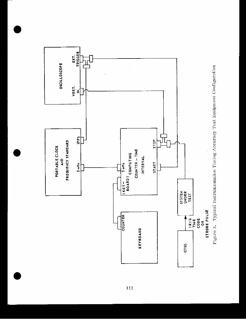
As shown in Figure 2, the distribution of thc IRIG time code formats A, 13, D, E and H and 1, 10, lOOpps and 1, 10 and 100kpps pulscs i s generally accomp- lished over telephone plant cable pairs o r a UHF radio system. The timing cir- cuits provide radar, telemetry and other instrumentation systems with standard time code formats. Total delays a t each site a r e then determined with a portable frequency standards and a computing counter, a s shown in Figure 3.
I Radar Synchronization
As shown in Figure 4, thc mastcr timing pulsc at each radar station is routed from the timing center to the radar area and then to radar equipment where interrogate pulses a r e initiated. It is these 20pps pulses which actually "freezett

i
WfK Ccntral T i m 'isd Gclirmtur (CM)
R'd5. Callfornla W-5Nd.4 Ces1m *am
Frtqwncy Srandard
Teiemtry Record sutim
W m : C Ccntral Tim i p a l kncrator (CIX.)
Bl~lg . 488, ilAkd, Callrunhid, IP-5ODLA Ceslm Beam breqwnry
M U E L Central Tim S ig ln l knerator (CIS) Canton lslsnd tU'"iilbL\
Ccrrrnl h a m Fxvqwncy S t a n d
bN/FPS-lb-l a d - 2 Fktric Radar
Interrugate Pulse
A N m - 1 8 kbtric Rildar Interrogate
5UK and LPK h t t n c System
I Celltral Tinr Sawla1 rrnerator (CTSti)
Kaena Pt. HP-506U
Califomla qrtlC.ll systen
Traceability to &YO nTTL7 through PTK standards and "flying c l d ' closures.
V:UTd, U a l l i o m ~ a - CISG/Slte Timing chstributed ~clt::rtv ,,;arz on lmdlmes.
Ccntcr , Hu11LLillg
UIF Tra-fillutter bbdFl - CfiWSite a UIF radio T i m I d . distributed
SAMT EC Instrumentation Systems UTC/IRIG Timing- and Frccluency Accuracy 'l'raceability to USNO


--I- --11----1-- 1
RADAR SITE
I I I - _ IRIG T i m Code I I Tick Dist.
I mlifior I
I I
I I I
L-,,,,, --------------- .-&---------A Figure 4. Multiple Radar Interrogator Time Tag Data Synchronization

tile data regis ters . 'l'he data i s tllcn "durr~yccl" and stored on tape, along with lirnjng. The dclay ol' thc: s t robc pulsc in relation to UTC is tlircctly ~ n ~ a s u r c c l quarterly. This tlelay i s :tdclcd to t l ~ c computccl drift of the mas t e r cloclr to
<t IOX1. obtain an cstirnn t c of the total ofi'sct on each oper. t '
A s rtn ad(1itional precaution, n 11:~cltup oesiurll st:intirtrd is located :it t21c r ada r sitc. Thc 20 pps pulses :Ire c o i ~ p a r c d with tllc ccsium 1 pps "on tirxlc" pulsc p r io r to each opcr:ition. If thc differcucc in tirnc betwccn the pulses 1s not with- in *25 ps of thc dcsignatcrl tlel:~v Tor the sllc, the actual ciifl'crence must l ~ e loggc.rl l ~ y tllc operator. Thus qu:irtci-ly incasurei~lcnts ~111s prc-opcration:~l chcclis nssurc that a l l i7nd:tr, data c:ln be ncuuratc:ly :~lignc.d for merging.
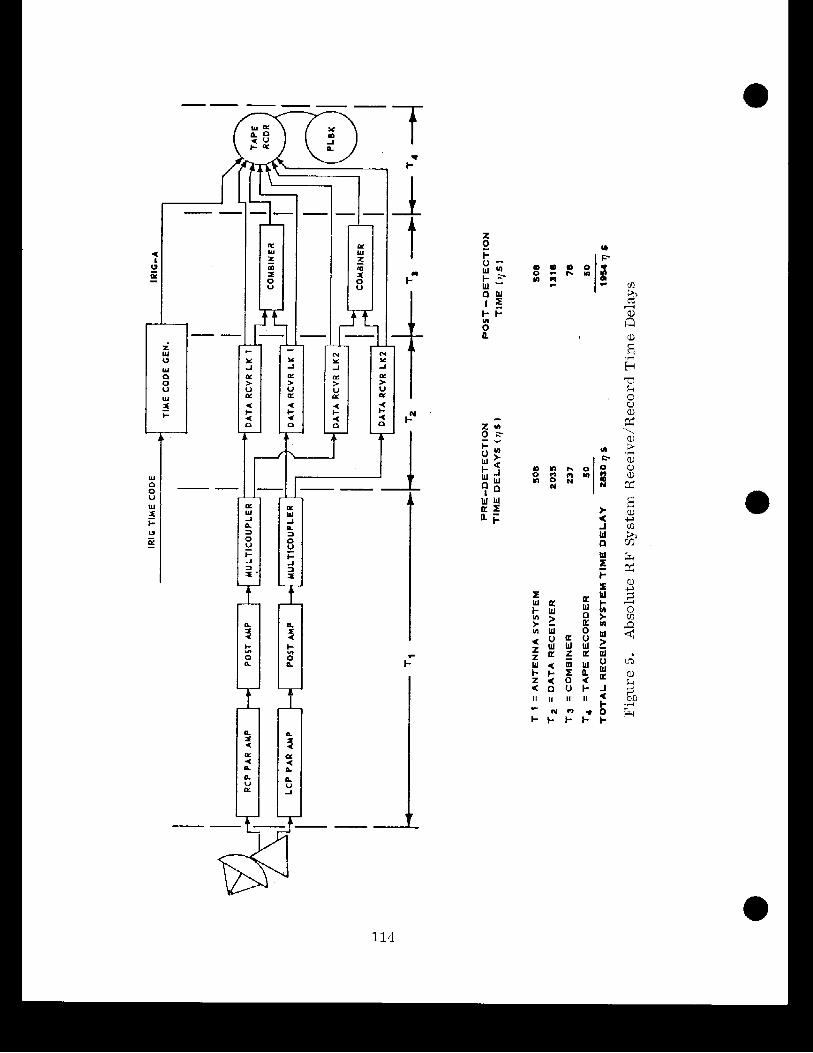
As shown in b'i,gulbr 5, tclcmel,ry stntlons synchronizr ti t j ~ n e cork generator to the incoining IRIG sigual. 'I'hc gclnerator lhen outputs "clcnn" IRIG linlltlg which i s ~ - ~ c o r d c d o n m:tgrlctic t:~pc. Also, dril:i l'rorn thc rct:civing systern is recordcrl on ;trIjac'cnl trac'lrs ol' thc s:liilc tape. lluring post flight processing, the iliagnetic t:tpc is replitycd, d:tta iinrl lirnltlg signtlls :Ire sllap(>tl, :mrl both :Ire irlp~lttccl for computcr j~roccssing. 1)art 01 thc p r o c e s s ~ n g ~~ccluirc~mt.nt js to uurrclnte r;ingc tirvlirlg to ttlc l ime of rlnt:~ rcccptlon a t tlie skition lo w ~ t l ~ i n onc co~npulcr wort1
0 Lilnc. ('l'ypically 1 7 8 Ps on cl'itic:ll 1)rogrnins). IJnlortun:tlcly, e r r o r s in the recorcJing/rbt.prorluc~ng s y s t t ~ m ]nay nccumulnte to scver:tl hundred rnicrvscconds atid must be corr.ectccl on lhe linal tlntit protluct, The signific:tnt contributions lo Ihc acctlnlulatctl e r r o r have I~ccn me:isurcrl, :inti a r c cllscussecl below.
:I. h'jgure 3 shows thc mcnrl ItF rcct:ivltlg system :i:tnrl recorclcr tilnc cle1:tys frbom t11rc.r :intcnna systcrrls for both precletcction :~tlcl post-dctcction rcscorcling.
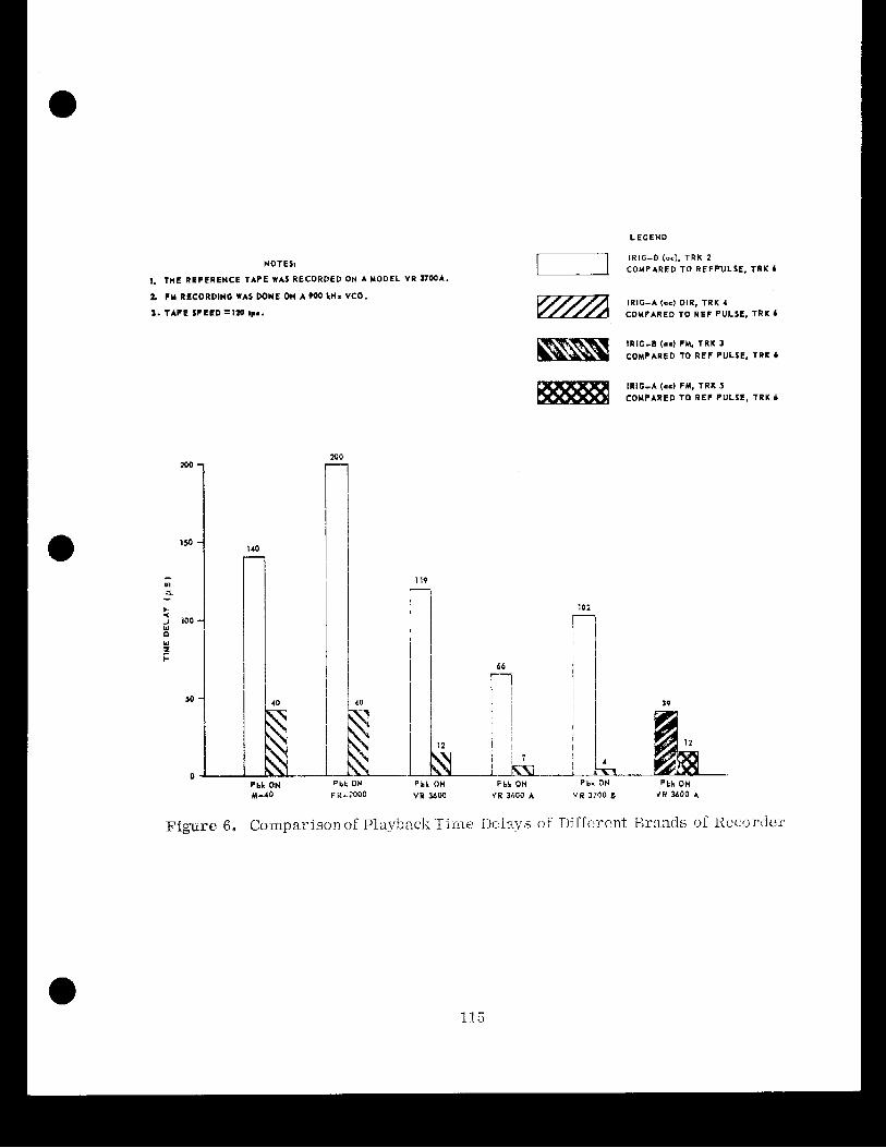
11. Scvcral models oS t:tpc rc-~cordcrs wer.t. Icstcrl. Figure li il1ustr;ttcs th:it each typc of rerorclcr rr::ic.ls rliffrrt.ntly In tht. IKIG A 101rllz :tncl IRK; I3 IkIT*, c:it.ric3rs. It was founci ns shown in Figurc 7, that a dubbed tape had approsim:~tcly t loul~lc~l the tin~cb de1:t-y of t h ~ orgjnnl lapc.
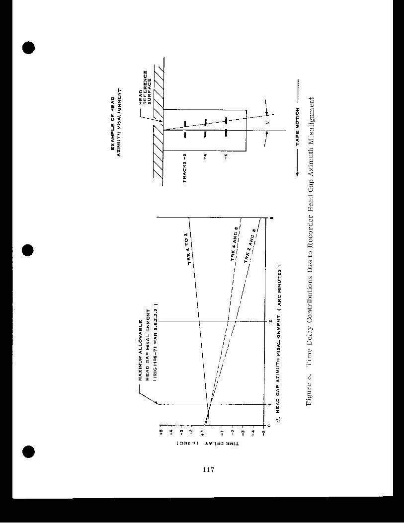
c. Hc:~tl :izirnuth aligtirncx~t c :~uscs only 1 v s of timing e r ro r , as sliowxl i n Figurc 4, if he:tds 31-I> :ilignc.rl within lRIG spcc ific:l lions.
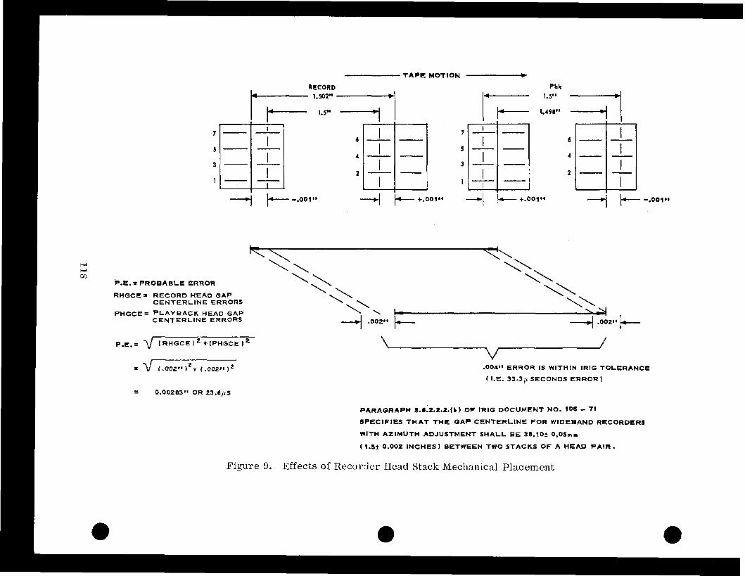
(1. As shown in Fig~:zlr,t. 9, and t:rror of u p to 3:: p s nixy resul t from :~llow- nlclle cvcn ant1 oclcl hcncl p1:tccment tolcr:~nces.
c. TJurjng pl:~yb:tclr, the tjxncl cotlc gcnerb:itor clccoclcs thc IRIG timing signal : ~ n d outpuls ti~rling pulscs forb cornputer use. As shown in E'iflre 10, i t was found that j i t ter on tht: pulscs was signific:int for IRI(; I3 cotles.
LEGEND
NOTES1
1, TME REFERENCE TAPE WAS RECORDED ON A MODEL VR n w * . 2 FM RECORDING WAS DONE ON A too kN= VCO.
1. TAPE SPEED =la Ips.
IR IG-B (0s). TRK 2 T I COMPARED TO REFPULSE, TRK 1
IRIG-8 (me) FH. T RK 3 COMPARED TO REF PULSE. TRK b
IRIG-A (me) FM, TRK 5 COMPARED TO REF PULSE, TRK 6
Pbk ON Pbk ON PLL ON Pbk OH Pbk ON
Figure 6. Comparison 01 P1:ivl)nck 'Ti lxc) I)c.l:xys o f nil'Sc.~.c.nt Er.:intls oS Kcc:~rdc:r.

T A P E MOTION - Pbk
1- 1.5.' -4
w CI ca
P.E. = PROBABLE ERROR
RHGCE= RECORD HEAD GAP CENTERLINE ERRORS
PHGCE= PLAYBACK HEAD GAP CENTERLINE ERRORS
.004" ERROR IS WITHIN IRlG TOLERANCE
( I.€. 3 3 . 3 ~ SECONDS ERROR 1
PARAGRAPH ~.6;2 .2 .2 .1~) OP lRlG DOCUMENT NO. 106 - 71
SPEClFlES THAT THE GAP CENTERLINE FOR WIDEBAND RECORDERS
WITH AZIMUTH ADJUSTMENT SHALL BE 30.10f 0,OSmm
t l.5f 0.002 INCHES I BETWEEN T W O STACKS OF A HEAD P A I R .
Figure 9. Effects of Recorder Head Stack Mechanical Placement

f. An unmodeled e r ro r occurs from timc to time when the recorder IRIG timing is noisy. Opcrators may Silter the data to obtain better lock. Such filtering introduces additional delay and amplilier inversion of the codc may introduce an unexpected timc dclay of one half cyclc (500 p sec for IRIG 13). Such errors , ol course, destroy the carelully controlled timing correlations.
Correction of Telemetry Er rors
The e r ro rs outlined above may accumulatc to several hundred microsecontls on a gjven data run. Fortunately, the e r ro r is a reasonably constant value and can be easily determined as follows,
Referring to Figure 11, thc dclay to the signal conditioner 1 js known to be less than 2 p s and is ignored. The conditioner introduces a 1 bit data delay and its output i s recorded on a rcdundant recorder track. Each 1 pps pulse from the time code generator switches the data off and inserts a prc-programmed word in the data. During processing, the special word can bc easily identified and the last tlat:~ bit prior to thc word inserted is noted. This is the data bit which was received within I bit time of :in even second mark (less the delay through the receiving system). The actual data produced from an uninterrupted (normal) input is then examined and the time provided by the computer for the reference bit dctcrmincd. This time should be an even sccond, Any deviation i s the accu- mulated timing e r ro r which existcd at thc even second. The mean and standard deviation of all 1 second rncasurements is obtained. Thjs provides the timing bias caused by thc accumulated error. The bias can bc rcmoved in subsequent processing operations.
Future Reuuirements
A range requirement may be received which requircs that the data received on two separate links be correlated to within A 0 U s . From the data provided above, it can be seen that cvcn if thc two data streams a r e rccordecl on thc same head stack and high frequency 1RlG codes a r c used, it will be difficult to control the computer inputs to within the required tolcrancc. 01' greater significance, however, is the soltware resolution of ? 1 word time in assigning timing "tags". This resolution must bc reduced to + 1 bit time to meet program objectives.
Future Needs
Although cesium standards have proven reliable, failures require that a "flying clock" be sent to tllc rcmotc sitc bctwcen normal calibration intervals. What i s nccdcd is a tcchniclue for synchronizing remote standartis to within *1 U s


without relying on a portable clock. Thc application of satellites has heen con- sidered and the accuracy appcars to be satjsfactory. Howcvcr, its application depends on the availability of inexpensivc receiving equipment which can com- pete, from a cost effectiveness standpoint, with the flying clock concept.
REFERENCES
1. Pickett, R. B. , "Improving Telemetry Timing AccuracyTT, International Telemetering Confercncc Proceedings, 1971.
2. Matthews , F. L . , "Timjng Accuracies 01 Range Instrumentation Systcmstl, International Tclcmetering Conference Procceclings, 1972.
3. Matthews, F. L. and Strcich, K. G. , "Timing Coxrclation in Telemetry Recording and Processing Systems", Intcrnational Telemctcring Conference Proceedings, 1973.
4. "Telemetry S tandarc l~~~, TRIG Document 106- 7.3 (Rcvised May 1973).
5. "Test Methods for Telcmctry Systems n.nd SubsystemslT, IRIG ilocurncnt 118-73 (Reviscd May 1973).
6. "TRIG Standard Time Forrn:~tsl~, IKJG Ilocumcnt 104-70 (Revised August 1970).
QUESrI'ION AND ANSWER PE1IIC)I)
MR. CIII:
A r e there any questions ?
You never mentioned the cluallty o r hand width ol' thc lines that you were using. I follnd that IRIG-I3 was even bcyoncl the c.apa1~ility of commercjnl telephone lines, and thc e r r o r ra te was unact:cptaI)le, :lncl w c went to thc FSK coding modems,
You a r e talking ahout using 100 ltilolicrbt7. You must 11:lve prbctty goor1 lincs.
If and when we rlo go lo the 100 l ; i loh~rtz , of course i t would be in the coax typc line.
Normally, ou r IRI(;-I3 is clistril~uted, when it js on telephone lines, on ;I 3 ICC circui t i and IItIG-A rccluires co:ix.
1 am very impressed hy the work which you llavc clcst~rihed. 'I'llel-c :ire several comments and ideas which 1 woulrl like to cxplore licrc with you.
Isn' t i t true thnt thc ahsolute tiinc difference whirh you have between your various channels on one and the same tape recol-der, i s l e s s of a problem than the fluctuations which you h:~vc not only from g:tp misalignment, but cvcn more so from changes in the tape tension, :ind changes in tlic t ;~pc type? If you use a different tape, T would expect you to have quite :I rljffcrhcnt clelay from chtinncl to chnnncl.
Don't forget that five microseconds nt a sprrcl of 1 2 0 inches per scconcl amounts to just n fcw microns of djfferencc in positinn a t any one moment.
For that reason, it appears to me that jt may br usrl'ul to m a l e :i t es t of trying to s u p ~ r i m p o s e 3 low level sine wave, which is dcrived from your. st:inclard, on the vcry same channel on which you havc your timing data coming in, which a r e , of course code modulated a t any rate.
So, you could separate them electrically, but you would have thc advnntagc of having passed all the signals, the timing signals, and your inform:ition ovcr exactly the same channels on the tape.
Another possibility, of course, would be to use a wide band video recordcr, and to put a l l your channels onto one c a r r i e r , and usc actually a c a r r i e r frccluency type of recording system.
But it is definitely pushing the possihilitics to the very end.
MR. MATTHEWS:
Well, I fajlcd to mcntion that we, in the alignment of our recorder heads, usetl thc lissajous patterns to n~nlie our alignment, ancl hnve found it very effective i n aligning up t l i ~ hcad, a s to the azimuth alignrncnt.
MR. 'ICLEINICC>PF:
Jack Kleinkopf here , from NASA Flight Rcsc:~rch Centcr, a t Edwards A i r Force Base.
One thing that I ditlnlt get clear -- maybe you covcrcd i t -- was the discrepancy between your snmplc (lakt system, thc P C M system, and the sample ra te on
e board, and the grouncl timing.
How do you go about resolving that?
MR. MATTHEWS:
I should say airborne timing is not available on the missiles that a r c flown out of Vandcnbcrg, and tliereforc all of the timing is generated from the ground system.
Does that answer your question ?
MR. K1,EINKOPF:
Well, do you have an oscillator in your airborne sample data system, and do you have a framc of P C M data coming in, so that thc post reduction analysis can go back and determine where the beginning of the frame of the P C M data i s with respect to your ground base time.
124

MR. MArI"I'HE WS:
Okay. Normally, t l ~ ~ r c a r r sprcific points in the flight that a r c known vcry ; t ccu ra t~ ly , nnrl we citn :~lign our data up with l ime a t these points, suc11 a s when they go through staging. These reprcscnt specific t imc intervals which we linow. A t those points we li110~ that :tt :I cert:iili t imc that, because of separation nr :~ttenu:~tion, we get dropouts. We also lmow that thcsc p:lrticul:~i* points in our tl:tt:~ s t ream :trbc cxact and that we call line the timing up with th:tL,
MR. Ii1,EINliC)PF:
I sce. You nrc s:iying this i s all 1)ased on a launch time, 01- sornet11i:lg like th:i t , initializfltion point.
MR. MATTIIEWS:
Wc record the Ijftoff tlrnc. Hut one of the points that 1 was pointing out, I believe on the las t sljdc t l ~ c r e , w;ts that in ortlcr lo mcasurc thc shsolrite t imc, we nerd to k~iow vcry :~ccur:it~:ly \vh:ir. thc timc tlclay differcnc? is between VTC and this one pps pulse where we inser t t l ~ e r~re-r)rogrnnlnlclci wo1.d into the data str(2anl wjth specifil recorder1 track.
That data i s pulled off, put into the computer., :~nd stol-ed, It is also looliing and averaging the t jmc of the niillisccontl ni:irkcr* - that i s , the lRIG t ime code goes into thr tirnc cotlc t ranslator . It then inputs the millisecond marke r s into t h e computer, and i t hno~vs a l :I ccrt:~in point this uiic pps pulsc takcs placr where that mjllisecontl n~:~rl;c:* should I)c. U'c thcn c a o r - r w t f o r that inillisecond mar-kcr.
MR. CHI:
Th:tnlc you again.