In Through the Out Door: Reconfiguring the NRL TEAMS Facility
25
D.L. Knies, K.S. Grabowski, and C. Cetina Naval Research Laboratory, Washington, DC 20375 In Through the Out Door: Reconfiguring the NRL TEAMS Facility
-
Upload
denton-santos -
Category
Documents
-
view
23 -
download
0
description
In Through the Out Door: Reconfiguring the NRL TEAMS Facility. D.L. Knies, K.S. Grabowski, and C. Cetina Naval Research Laboratory, Washington, DC 20375. Outline. Introduction to TEAMS at NRL Addition of IMS-6f S vs. U bend and ramifications Beam Optics for the RBS and Implant Beamlines - PowerPoint PPT Presentation
Transcript of In Through the Out Door: Reconfiguring the NRL TEAMS Facility

D.L. Knies, K.S. Grabowski, and C. CetinaNaval Research Laboratory, Washington, DC 20375
In Through the Out Door:Reconfiguring the NRL TEAMS Facility
Outline
• Introduction to TEAMS at NRL• Addition of IMS-6f• S vs. U bend and ramifications• Beam Optics for the RBS and Implant Beamlines• Conclusions

NRL TEAMS Facility
Pelletron Accelerator
C stripper foil
+ ions
SiU
30˚ Electrostatic Analyzer
3˚ Bend Selects Charge State
- ions
+3 MV
Pretzel Magnet
Mass Filter
60 keV Accel.
Sample
Switchable 45˚ electrostatic
analyzer
110 feet
27˚ BendIon Implantation
Beam Line (500 keV–12 MeV)
55˚ Bend Surface Analysis
Beam Line
Beam Line Switching Magnet
SIMS Ion Source
Plasma Ion Source (4He)
40 cathode sputtering ion
source

Key Elements of the NRL TEAMS Facility
Along with fiber optic telemetry/control and LabView user interface, provides • Stable and convenient operation.• Isotope analysis with 10-15 sensitivity (e.g., 14C)• Trace element analysis with 10-11 sensitivity for multiple elements in parallel
Input
Pretzel Magnet
Output
H Si Fe Ce USymmetry axis
Factor of 8 Mass RangeMass Resolution M/M >25001.5 Meter Focal Plane

IMS 6f as a Clean Ion Source

Current Low End Configuration
EQT
SwitchingESA
MC-SNICS
PretzelMagnet &Chopper
8 ft

Current Configuration 3º Bend for Charge State Selection
3º Bend

New Configuration 15º Bend for Charge Selection, Tank Flipped 180º

New Injector Requirements
• Maintain current capability (40-70 keV injection)
– TEAMS (MC-SNICS)– 14C AMS (MC-SNICS)– Ion Implantation (tross/MC-SNICS)– RBS and ERD (tross)– HIBS (MC-SNICS)
• Direct injection form IMS 6f (10 keV Injection)
• Variable Terminal Voltage Operation

Einzel Lenses in Tank

10 KeV to 60 KeV Injection
10 keV :1 MV
Einzel #2Einzel #1
L.E. Tube Stripper
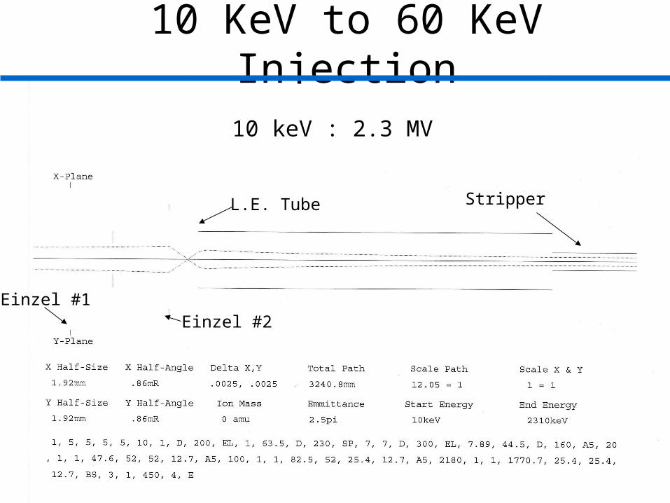
10 KeV to 60 KeV Injection
10 keV : 2.3 MV
Einzel #2Einzel #1
L.E. Tube Stripper

10 KeV to 60 KeV Injection
40 keV :1 MV
Einzel #2
Einzel #1
L.E. Tube Stripper

10 KeV to 60 KeV Injection
60 keV :3 MV
Einzel #2
Einzel #1
L.E. Tube Stripper

SIMION 7.0 in TransportAxial Electric Field and Electric Potential
1.75" Einzel Lens
0
2000
4000
6000
8000
10000
12000
0 20 40 60 80 100 120 140
Position (mm)
Po
ten
tia
l (V
olt
s)
-500
-400
-300
-200
-100
0
100
200
300
400
500
Ele
ctr
ic F
ield
(V
/mm
)
Voltage
Electric Field

Calculated, using SIMION 7.0 Electric Fields to Model the Einzel Lenses and Accelerator Tubes in Transport.
10 KeV C- Injection to Terminal 2.7 MV
L.E. ESA
Pretzel Einzel
L.E. TubeEinzel #1
Einzel #2 Stripper

60 KeV C- Injection to Terminal 2.7 MV
Calculated, using SIMION 7.0 Electric Fields to Model the Einzel Lenses and Accelerator Tubes in Transport.
L.E. ESA
Pretzel Einzel
L.E. TubeEinzel #1
Einzel #2 Stripper

12C Optics 2.7 at High End 0.1% Momentum Spread at 2.7 MV Terminal
Calculated, using SIMION 7.0 Electric Fields to Model the Einzel Lenses and Accelerator Tubes in Transport.
H.E. Tube
Stripper
15º Bend
30º ESA
Split-Pole
HE EQT 1HE EQT 2

15º Charge State Selection
Charge State
Energy BendAngle
BeamDeflection
BeamSeparation
q MeV Degree mm mm
1 6.07 9.0 453 -308
2 9.07 12.0 607 -155
3 12.07 13.5 684 -78
4 15.07 14.4 731 -31
5 18.07 15.0 762 0
6 21.07 15.5 784 22
7 24.07 15.8 800 39
Source Voltage = 0.07 MV, Terminal Voltage = 3.00 MV, Total Plate Voltage 72.5 kV, Gap = 50 mm, Drift 2.90 M

NRL High Energy Beamline Split-pole Stripper to Split-pole
k0
3
δ
x
0
0
0
1111
111
2222
222
3
3
3
1000
0100
''/1/1
0
1000
0100
''/1/1
0
m
km
km
km
km
k
k
x
DDMf
DDM
DDMf
DDM
To form an angle- and energy-focusing spectrometer we require the image at x3 to be independent of k0.
2122120012 kkmmm DDMDDMxMM k03 δx
or 0212 kk DDM
The split-pole is a complicated magnet with,
36.033.02 M and 05.19.02/222 DDD mk
.
The -1/3 magnification requires an energy-to-charge dispersion from our high energy tube and compound ESA of ~ 2.8.

U-Bend vs. S Bend2.7 MV Terminal 12C, q3+, With and without 0.1% Momentum Spread
S-Bend 0.1 %U-Bend 0.1 %
U-Bend = 0.7 mm/%
S-Bend = 10 mm/%
Energy Dispersion
Focal Plane
S- or U-Bend no spread

U-Bend Bend
m = 0.74% and δk = 0.0%Focal Plane
m = 0.74% and δk = 0.1%
m = 0% and δk = 0.1%
m = δk = 0.0%

27º Implant Beamline2.7 MV Terminal 12C, q3+, with and without 0.1% Momentum Spread
QuadrupoleDoublet
SwitchingMagnet
QuadrupoleDoublet
Neutral TrapScanner
End Station

55º Beamline2.7 MV Terminal 12C, q3+, with and without 0.1% Momentum Spread
QuadrupoleDoublet
SwitchingMagnet
QuadrupoleDoublet
End Station

Conclusions
• New IMS-6f as TEAMS ion source• Designed injector that can do it all• Improved charge state selection• Using all-natural focusing for the AMS beamline
(removed two quads and ~10 meter of flight path)
• Designed an energy-insensitive mass focusing spectrometer
• Using Split-pole as the analyzing magnet for RBS and Implant Beamlines
Work supported by ONR and NASA