IN THE UNITED STATES PATENT AND TRADEMARK OFFICE BEFORE...
68
IN THE UNITED STATES PATENT AND TRADEMARK OFFICE BEFORE THE PATENT TRIAL AND APPEAL BOARD Valeo North America, Inc., Valeo S.A., Valeo GmbH, Valeo Schalter und Sensoren GmbH, and Connaught Electronics Ltd. Petitioners v. Magna Electronics, Inc. Patent Owner U.S. Patent No. 8,643,724 Case IPR2015- To be Assigned Mail Stop PATENT BOARD Patent Trial and Appeal Board United States Patent and Trademark Office Madison Building (East) 600 Dulany Street Alexandria, VA 22313 PETITION FOR INTER PARTES REVIEW U.S. PATENT NO. 8,643,724
Transcript of IN THE UNITED STATES PATENT AND TRADEMARK OFFICE BEFORE...
IN THE UNITED STATES PATENT AND TRADEMARK OFFICE
BEFORE THE PATENT TRIAL AND APPEAL BOARD
Valeo North America, Inc., Valeo S.A., Valeo GmbH, Valeo Schalter und Sensoren GmbH,
and Connaught Electronics Ltd. Petitioners
v.
Magna Electronics, Inc. Patent Owner
U.S. Patent No. 8,643,724 Case IPR2015- To be Assigned
Mail Stop PATENT BOARD Patent Trial and Appeal Board United States Patent and Trademark Office Madison Building (East) 600 Dulany Street Alexandria, VA 22313
PETITION FOR INTER PARTES REVIEW U.S. PATENT NO. 8,643,724
Petition for Inter Partes Review of U.S. Patent No. 8,643,724
i
TABLE OF CONTENTS
I. INTRODUCTION ...........................................................................................1
II. MANDATORY NOTICES .............................................................................3
A. Real Party-In-Interest ............................................................................3
B. Related Matters .....................................................................................3
C. Lead and Back-up Counsel ...................................................................4
D. Service Information ...............................................................................4
III. PAYMENT OF FEES ......................................................................................5
IV. REQUIREMENTS FOR INTER PARTES REVIEW ......................................5
A. Grounds for Standing ............................................................................5
B. Identification of Challenge ...................................................................6
1. The Specific Art and Statutory Ground(s) on Which the Challenge Is Based......................................................................6
2. How the Construed Claims Are Unpatentable and Supporting Evidence Relied Upon to Support the Challenge .................... 10
V. FACTUAL BACKGROUND ....................................................................... 11
A. Declaration Evidence ......................................................................... 11
B. The State of the Art ............................................................................ 14
C. Summary of the ’724 Patent ............................................................... 18
D. Summary of the Prosecution History ................................................. 20
VI. BROADEST REASONABLE CONSTRUCTION ...................................... 20
A. Construction of terms used in the challenged claims ........................ 21
B. How the Construed Claims Are Unpatentable and Supporting Evidence Relied Upon to Support the Challenge .............................. 25
Petition for Inter Partes Review of U.S. Patent No. 8,643,724
ii
VII. GROUNDS OF UNPATENTABILITY ON WHICH PETITIONER IS LIKELY TO PREVAIL ................................................................................ 25
A. Claims 1-18, 20, 22, 23, 25, 29, 30, 31, 32, 41, 42, 43, and 48 of the ‘724 Patent are obvious over Nissan, Hino, and Lemelson ............... 25
B. Claim 19 of the ‘724 Patent is obvious over Nissan, Hino, Lemelson, and Wang. ........................................................................................... 43
C. Claim 21 is obvious over Nissan, Hino, Lemelson, and Aishin. ....... 44
D. Claim 24 is obvious over Nissan, Hino, Lemelson, and Niles. ......... 45
E. Claim 26 is obvious over Nissan, Hino, Lemelson, Aishin, and Schmidt. .............................................................................................. 47
F. Claims 27 and 28 are obvious over Nissan, Hino, Lemelson, and Fuji. ............................................................................................................ 49
G. Claims 33, 35, and 36-38 are obvious over Nissan, Hino, Lemelson, and Otsuka. ......................................................................................... 51
H. Claim 34 is obvious over Nissan, Hino, Lemelson, Otsuka, and Conner. ............................................................................................... 53
I. Claim 39 is obvious over Nissan, Hino, Lemelson, Otsuka, and Sato. ............................................................................................................ 53
J. Claim 40 is obvious over Nissan, Hino, Lemelson, Otsuka, and Paff. ............................................................................................................ 54
K. Claim 44 is obvious over Nissan, Hino, Lemelson, and King. ......... 55
L. Claim 45 is obvious over Nissan, Hino, Lemelson, and Goesch ...... 57
M. Claims 46 and 47 are obvious over Nissan, Hino, Lemelson, and Lelong. ................................................................................................ 58
VIII. CONCLUSION ............................................................................................. 59
Petition for Inter Partes Review of U.S. Patent No. 8,643,724
iii
EXHIBIT LIST
Ex. 1001 U.S. Pat. No. 8,643,724 to Schofield.
Ex. 1002 U.S Pat. No. 6,553,130 to Lemelson.
Ex. 1003 Japanese Publication No. JP3099952 assigned to Nissan Motor Co., Ltd.
Ex. 1004 Certified English Translation of Japanese Publication No. JP3099952 assigned to Nissan Motor Co., Ltd.
Ex. 1005 Japanese Publication No. JPA64-14700 assigned to Aishin Warner Kabushiki-Kaisha.
Ex. 1006 Certified English Translation of Japanese Publication No. JPA64-14700 assigned to Aishin Warner Kabushiki-Kaisha.
Ex. 1007 Japanese Publication No. 62-16073 assigned to Hino Motors Ltd.
Ex. 1008 Certified English Translation of Japanese Publication No. 62-16073 assigned to Hino Motors Ltd.
Ex. 1009 Wang, G., et al. "CMOS Video Cameras", IEEE, 1991, dated May 27-31, 1991.
Ex. 1010 Great Britain Patent No. GB 2233530 assigned to Fuji Jukogyo Kabushiki Kaisha.
Ex. 1011 Japanese Publication No. H2-36417 assigned to Niles Co., Ltd.
Ex. 1012 Certified English Translation of Japanese Publication No. H2-36417 assigned to Niles Co., Ltd.
Ex. 1013 U.S Patent No. 5,444,478 to Lelong.
Ex. 1014 U.S. Patent No. 4,693,788 to King.
Ex. 1015 U.S. Patent No. 4,966,441 to Conner.
Ex. 1016 U.S. Patent No. 5,793,420 to Schmidt.
Petition for Inter Partes Review of U.S. Patent No. 8,643,724
iv
Ex. 1017 SAE Paper No. 871288 to Otsuka.
Ex. 1018 U.S. Patent No. 4,833,534 to Paff.
Ex. 1019 Expert Declaration of Dr. George Wolberg
Ex. 1020 Expert Declaration of Dr. Ralph Wilhelm
Ex. 1021 U.S. Patent No. 4,390,895 to Sato.
Ex. 1022 SAE Paper No. 890288 to Goesch.
Ex. 1023 Japanese Article “Television Image Engineering Handbook, The Institute of Television Engineers of Japan” (“JP Handbook”).
Ex. 1024 English Translation of Japanese Article “Television Image Engineering Handbook, The Institute of Television Engineers of Japan” (“JP Handbook”).
Ex. 1025 Dr. George Wolberg Curriculum Vitae
Ex. 1026 Robert Nathan, Digital Video Data Handling, NASA JPL Tech Report 32-877, Pasadena, CA, Jan. 5, 1966.
Ex. 1027 P. Burt et al., A Multiresolution Spline with Application to Image Mosaics, ACM Transactions on Graphics, Vol. 2. No. 4, Pages 217-236, October 1983.
Ex. 1028 Lisa Gottesfeld Brown, A Survey of Image Registration Techniques, vol. 24, ACM Computing Surveys, pp. 325-376, 1992.
Ex. 1029 George Wolberg, Digital Image Warping, IEEE Computer Society Press, 1990.
Ex. 1030 N. Greene et al., Creating Raster Omnimax Images from Multiple Perspective Views Using the Elliptical Weighted Average Filter, IEEE Computer Graphics and Applications, vol. 6, no. 6, pp. 21-27, June 1986.
Ex. 1031 Richard Szeliski, Image Mosaicing for Tele-Reality Applications, DEC Cambridge Research Laboratory, CRL 94/2, May 1994.
Petition for Inter Partes Review of U.S. Patent No. 8,643,724
v
Ex. 1032 G. Wolberg, “A Two-Pass Mesh Warping Implementation of Morphing,” Dr. Dobb’s Journal, no. 202, July 1993.
Ex. 1033 T. Porter and T. Duff, “Compositing Digital Images,” Computer
Graphics (Proc. Siggraph), vol. 18, no. 3, pp. 253-259, July 1984.
Ex. 1032 G. Wolberg, “A Two-Pass Mesh Warping Implementation of Morphing,” Dr. Dobb’s Journal, no. 202, July 1993.
Ex. 1033 T. Porter and T. Duff, “Compositing Digital Images,” Computer
Graphics (Proc. Siggraph), vol. 18, no. 3, pp. 253-259, July 1984.
Ex. 1034 Dr. Ralph V. Wilhelm Curriculum Vitae
Ex. 1035 SAE Paper No. 750364 to Nolan
Ex. 1036 SAE Paper No. 890282 to Corsi
Ex. 1037 SAE Paper No. 890283 to Brandt
Ex. 1038 SAE Paper No. 860173 to Ortega
Ex. 1039 SAE Paper No. 930456 to Gumkowski
Ex. 1040 U.S. Patent No. 6,693,524 to Payne
Ex. 1041 SAE Paper No. 770274 to Smith
Petition for Inter Partes Review of U.S. Patent No. 8,643,724
1
I. INTRODUCTION
Petitioners Valeo North America, Inc., Valeo S.A., Valeo GmbH, Valeo
Schalter und Sensoren GmbH, and Connaught Electronics Ltd. (collectively
“Valeo” or “Petitioner”) respectfully request inter partes review of claims 1-48
(the “challenged claims”) of U.S. Patent No. 8,643,724 (“the ’724 patent,”
attached as Ex. 1001) in accordance with 35 U.S.C. §§ 311-319 and 37 C.F.R. §
42.100 et seq.
The ’724 patent is generally directed to a vision system for a motor vehicle.
More particularly, the ’724 patent is directed to a multi-camera vision system for a
vehicle that includes two or three vehicle-mounted image capture devices (i.e.,
cameras), an image processor, and a display to provide the driver with perspective
of the vehicle’s surroundings. (Ex. 1001 at 2:23-35; 2:59-3:221 and Fig. 8). The
image processor synthesizes the image portions captured by each of the image
capture devices. That image processing results in a synthesized image
characterized by the absence of duplicate objects, which might otherwise appear in
1 This petition cites to various exhibits by citing page (or column) and line number
references (where applicable), as follows: “Ex. [No.] at [page/column]:[lines].”
Citations to page numbers within non-patent publications refer to the document’s
original pagination as displayed therein.
Petition for Inter Partes Review of U.S. Patent No. 8,643,724
2
images due to the cameras capturing images having overlapping fields of view.
(Id. at 7:5-16; 7:44-57; Fig. 3). Ultimately, the driver views a synthesized image
on the display inside the vehicle on a reconfigurable display device such that
auxiliary information other than the synthesized image may be shown to the
driver. The driver (or another user) may select the types of information displayed
on the reconfigurable display.
As demonstrated by various prior art references, motor vehicle vision
systems and methods for processing image data to display a synthesized image to a
driver of the vehicle and reconfigurable displays were well known to a person
having ordinary skill in the art (hereinafter “PHOSITA”) well before May 22,
1996, the earliest claimed priority date of the ’724 patent. Although some of these
prior art references were made of record via an Information Disclosure Statement
in the application that resulted in the ’724 patent (App. No. 13/800,691), the
Examiner did not specifically cite or discuss any of these references during the
prosecution of the ’724 patent.
For example, JP3099952, assigned to Nissan Motor Co. (“Nissan,” certified
English translation at Ex. ’1004), discloses a vehicle surroundings monitoring
system having one or a plurality of cameras installed in a vehicle, converting
images input by the cameras to other coordinates by a perspective conversion,
combining the converted images into one image related to an image of the vehicle
Petition for Inter Partes Review of U.S. Patent No. 8,643,724
3
itself, and a display for displaying the image to the vehicle occupants. Ex. 1004 at
2:5-12. Hino discloses synthesizing image data captured by multiple cameras on a
vehicle to depict a view from the perspective of a virtual camera located directly
above the vehicle. Ex. 1008 at Fig. 3. Further, Lemelson discloses a robust driver
awareness system having, among other things, a forward-facing camera with a
reconfigurable display on which various auxiliary information may be displayed,
in addition to the video images captured by the camera. See Ex. 1002 at 6:46-54;
15:45-53.
For the reasons discussed in Section VII (below) and in the declarations of
Dr. George Wolberg and Dr. Ralph Wilhelm, submitted in support of this petition,
prior art references Nissan, Hino, and Lemelson, and other references described
below render the challenged claims of the ’724 patent obvious.
II. MANDATORY NOTICES
Pursuant to 37 C.F.R. § 42.8(b), Petitioner provides the following
mandatory disclosures.
A. Real Party-In-Interest
Pursuant to 37 C.F.R. § 42.8(b)(1), Petitioner certifies that Valeo North
America, Inc., Valeo S.A., Valeo GmbH, Valeo Schalter und Sensoren GmbH, and
Connaught Electronics Ltd. are the real parties-in-interest.
B. Related Matters
Petition for Inter Partes Review of U.S. Patent No. 8,643,724
4
Pursuant to 37 C.F.R. § 42.8(b)(2), Petitioner states that the ’724 patent is
involved in the litigation styled Magna Electronics Inc. v. Valeo, Inc., et al.,
No. 2:14-cv-10540 (E.D. Mich. filed Feb. 5, 2014; Amended Complaint filed
March 19, 2014). This litigation remains pending. One of the three patents-in-suit
is the ’724 Patent, attached as Ex. 1001.
Petitioner will be filing a motion to stay the corresponding district court
litigation pending the conclusion of the Inter Partes Review proceedings.
C. Lead and Back-up Counsel
Pursuant to 37 C.F.R. § 42.8(b)(3), Petitioner provides the following
designation of counsel:
Lead Counsel Back-up Counsel
Tammy J. Terry (Reg. No.: 69,167) [email protected] OSHA LIANG LLP 909 Fannin Street, Suite 3500 Houston, TX 77010-1034 Phone: (713) 228-8600 Fax: (713) 228-8778
Seema Mehta (Reg. No.: 56,235) [email protected] Aly Dossa (Reg. No.: 63,372) [email protected] Peter C. Schechter (Reg. No.: 31,662) [email protected] OSHA LIANG LLP 909 Fannin Street, Suite 3500 Houston, TX 77010-1034 Phone: (713) 228-8600 Fax: (713) 228-8778
Pursuant to 37 C.F.R. § 42.10(b), a Power of Attorney accompanies this
Petition.
D. Service Information
Pursuant to 37 C.F.R. § 42.8(b)(4), papers concerning this matter should be
Petition for Inter Partes Review of U.S. Patent No. 8,643,724
5
served on lead and backup counsel whose service information is provided above.
Petitioner consents to service of papers in this proceeding by e-mail.
III. PAYMENT OF FEES
The undersigned authorizes the Office to charge $41,800 to the deposit
account designated and used for payment during e-filing as the fee required by 37
C.F.R. §42.15(a) for this Petition for Inter Partes Review. Review of forty-eight
(48) claims is being requested, so an excess claims fee is included in this fee
calculation. Any additional fees or credit of overpayment that might be due in
connection with this Petition may be charged to Deposit Account No. 50-0591
(Ref. No. 18096/008001).
IV. REQUIREMENTS FOR INTER PARTES REVIEW
As set forth below and pursuant to 37 C.F.R. § 42.104, each requirement for
inter partes review of the ’724 patent is satisfied.
A. Grounds for Standing
Pursuant to 37 C.F.R. § 42.104(a), Petitioner hereby certifies that the ’724
patent is available for inter partes review and that the Petitioner is not barred or
estopped from requesting inter partes review challenging the claims of the ’724
patent on the grounds identified herein. The ’724 patent has not been subject to a
previous estoppel based proceeding of the America Invents Act (AIA), and the
complaint was served within the last twelve months.
Petition for Inter Partes Review of U.S. Patent No. 8,643,724
6
B. Identification of Challenge
Pursuant to 37 C.F.R. §§ 42.104(b)(1), Petitioner requests inter partes
review and cancellation of claims 1-48 of the ’724 patent.
1. The Specific Art and Statutory Ground(s) on Which the
Challenge Is Based
Pursuant to 37 C.F.R. § 42.104(b)(2), inter partes review of the ’724 patent
is requested in view of the following references, each of which is prior art to the
’724 patent under 35 U.S.C. § 102(a), (b), and/or (e):2
(1) Japanese Publication No. JP3099952 assigned to Nissan Motor
Co., Ltd., (“Nissan,” Ex. 1003 (certified English translation at Ex. 1004))
published on April 25, 1991, from an application filed on September 12, 1989.
Because it published more than one year before the filing date for the ’724 patent
(May 22, 1996), Nissan is prior art to the ’724 patent under 35 U.S.C. § 102(b).
See also Ex. 1019 at ¶¶ 62-71.
(2) Japanese Publication No. 62-16073 assigned to Hino Motors Ltd.
(“Hino,” Ex. 1007 (certified English translation at Ex. 1008)) published on April
10, 1987, from an application filed on December 23, 1981. Because it published
more than one year before the filing date for the ’724 patent, Hino is prior art to
2 The pre-AIA versions of 35 U.S.C. §§ 102 and 103 apply to the claims of the
pre-AIA ’724 patent.
Petition for Inter Partes Review of U.S. Patent No. 8,643,724
7
the ’724 patent under 35 U.S.C. § 102(b). See also Ex. 1019 at ¶¶ 72-75.
(3) U.S Patent No. 6,553,130 to Lemelson (“Lemelson,” Ex. 1002) was
filed on June 28, 1996, and claims benefit to a parent application filed on August
11, 1993. Because Lemelson’s effective filing date (August 11, 1993) was before
the ’724 patent’s earliest priority date (May 22, 1996 ), Lemelson is prior art to the
’724 patent under 35 U.S.C. § 102(e). See also Ex. 1020 at ¶¶ 44-48.
(4) Japanese Publication No. JP A64-14700 assigned to Aishin Warner
Kabushiki-Kaisha (“Aishin,” Ex. 1005 (certified English translation at Ex. 1006))
published on January 18, 1989, from an application filed on July 8, 1987. Because
it published more than one year before the filing date for the ’724 patent, Aishin is
prior art to the ’724 patent under 35 U.S.C. § 102(b). See also Ex. 1019 at ¶¶76-
82.
(5) Wang, G., et al. “CMOS Video Cameras”, IEEE, 1991, p. 100-103,
(“Wang,” Ex. 1009) published on May 27-31, 1991. Because it published more
than one year before the filing date for the ’724 patent, Wang is prior art to the
’724 patent under 35 U.S.C. § 102(b). See also Ex. 1019 at ¶¶ 36 and 83-85.
(6) Japanese Publication No. 59-114139 assigned to Niles Co., Ltd.
(“Niles,” Ex. 1011 (certified English translation attached as Ex. 1012)) published
on July 2, 1984, as a result of a Japanese patent application filed on
December 17, 1982. Because it published more than one year before the filing
Petition for Inter Partes Review of U.S. Patent No. 8,643,724
8
date for the ’724 patent, Niles is prior art to the ’724 patent under 35 U.S.C.
102(b). See also Ex. 1019 at ¶¶ 86-89.
(7) GB Patent No. 2,233,530 assigned to Fuji Jukogyo Kabushiki Kaisha
(“Fuji,” Ex. 1010) published on January 9, 1991, from an application filed on May
14, 1990. Because it published more than one year before the filing date for the
’724 patent, Fuji is prior art to the ’724 patent under 35 U.S.C. § 102(b). See also
Ex. 1020 at ¶¶ 49-52.
(8) U.S. Patent No. 5,444,478 to Lelong (“Lelong,” Ex. 1013) published
on August 22, 1995, from an application filed on December 28, 1993. Because
Lelong’s publication and filing dates (August 22, 1995 and December 28, 1993,
respectively) were before the ’724 patent’s earliest priority date (May 22, 1996),
Lelong is prior art to the ’724 patent under 35 U.S.C. § 102(e). See also Ex. 1019
at ¶¶ 90-93.
(9) U.S. Patent No. 4,963,788 to King (“King,” Ex. 1014) issued on
October 16, 1990. King is prior art to the ’724 patent under 35 U.S.C. § 102(b).
See also Ex. 1020 at ¶¶ 53-56.
(10) U.S. Patent No. 4,966,441 to Conner (“Conner,” Ex. 1015) issued on
October 30, 1990. Conner is prior art to the ’724 patent under 35 U.S.C. § 102(b).
See also Ex. 1020 at ¶¶ 57-60.
(11) U.S. Patent No. 5,793,420 to Schmidt (“Schmidt,” Ex. 1016) issued
Petition for Inter Partes Review of U.S. Patent No. 8,643,724
9
on August 11, 1998, from an application filed on February 20, 1996. Because
Schmidt’s filing date (February 20, 1996) was before the earliest priority date for
the ’724 patent (May 22, 1996), Schmidt is prior art to the ’724 patent under 35
U.S.C. § 102(e). See also Ex. 1020 at ¶¶ 61-63.
(12) SAE Paper No. 871288 to Otsuka et al. (“Otsuka,” Ex. 1017)
published on November 8, 1987. Because it published more than one year before
the filing date for the ’724 patent, Otsuka is prior art to the ’724 patent under 35
U.S.C. § 102(b). See also Ex. 1020 at ¶¶ 67-69.
(13) U.S. Patent No. 4,833,534 to Paff (“Paff,” Ex. 1018) issued on May
23, 1989. Paff is prior art to the ’724 patent under 35 U.S.C. § 102(b). See also
Ex. 1020 at ¶¶ 64-66.
(14) U.S. Patent No. 4,390,895 to Sato (“Sato,” Ex. 1021) issued on June
28, 1983. Sato is prior art to the ’724 patent under 35 U.S.C. § 102(b). See also
Ex. 1020 at ¶¶ 70-72.
(15) SAE Paper No. 890288 to Goesch (“Goesch,” Ex. 1022) published on
February 1, 1989. Because it published more than one year before the filing date
for the ’724 patent, Goesch is prior art to the ’724 patent under 35 U.S.C. §
102(b). See also Ex. 1020 at ¶¶ 73-77.
The Challenged Claims of the ’724 patent are unpatentable under 35 U.S.C.
§ 103(a) as being obvious over the prior art. Specifically:
Petition for Inter Partes Review of U.S. Patent No. 8,643,724
10
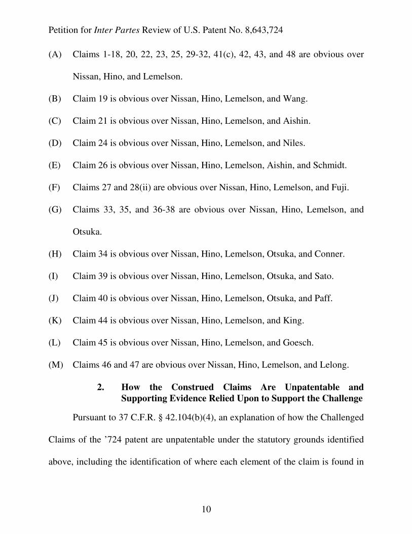
(A) Claims 1-18, 20, 22, 23, 25, 29-32, 41(c), 42, 43, and 48 are obvious over
Nissan, Hino, and Lemelson.
(B) Claim 19 is obvious over Nissan, Hino, Lemelson, and Wang.
(C) Claim 21 is obvious over Nissan, Hino, Lemelson, and Aishin.
(D) Claim 24 is obvious over Nissan, Hino, Lemelson, and Niles.
(E) Claim 26 is obvious over Nissan, Hino, Lemelson, Aishin, and Schmidt.
(F) Claims 27 and 28(ii) are obvious over Nissan, Hino, Lemelson, and Fuji.
(G) Claims 33, 35, and 36-38 are obvious over Nissan, Hino, Lemelson, and
Otsuka.
(H) Claim 34 is obvious over Nissan, Hino, Lemelson, Otsuka, and Conner.
(I) Claim 39 is obvious over Nissan, Hino, Lemelson, Otsuka, and Sato.
(J) Claim 40 is obvious over Nissan, Hino, Lemelson, Otsuka, and Paff.
(K) Claim 44 is obvious over Nissan, Hino, Lemelson, and King.
(L) Claim 45 is obvious over Nissan, Hino, Lemelson, and Goesch.
(M) Claims 46 and 47 are obvious over Nissan, Hino, Lemelson, and Lelong.
2. How the Construed Claims Are Unpatentable and
Supporting Evidence Relied Upon to Support the Challenge
Pursuant to 37 C.F.R. § 42.104(b)(4), an explanation of how the Challenged
Claims of the ’724 patent are unpatentable under the statutory grounds identified
above, including the identification of where each element of the claim is found in
Petition for Inter Partes Review of U.S. Patent No. 8,643,724
11
the prior art, is provided in Section VII below, in the form of claims charts.
Pursuant to 37 C.F.R. § 42.104(b)(5), the Exhibit numbers of the supporting
evidence relied upon to support the challenges and the relevance of the evidence
to the challenges raised, including identifying specific portions of the evidence
that support the challenges, are provided in Section VII below, in the form of
claim charts.
V. FACTUAL BACKGROUND
A. Declaration Evidence
This Petition is supported by the declarations of Dr. George Wolberg
(attached as Ex. 1019) and Dr. Ralph Wilhelm (attached as Ex. 1020). Both
experts offer their opinions with respect to the content and state of the prior art, as
well as the subject matter of the ’724 patent.
Dr. Wolberg is a professor of Computer Science at the City College of New
York and has studied and worked in the field of Computer Science, specifically
focusing on Image Processing, Computer Vision, and Computer Graphics, since
1985. After earning his Ph.D. in Computer Science from Columbia University in
1990, Dr. Wolberg joined the City College of New York as an assistant professor,
where he has continued his research and teaching in image processing, computer
graphics, and computer vision to the present day. Dr. Wolberg also is a Senior
Member of the IEEE and a member of ACM SIGGRAPH, as well as a co-founder
Petition for Inter Partes Review of U.S. Patent No. 8,643,724
12
and Chief Technology Officer of a private company, Brainstorm Technology.
In 1990, Dr. Wolberg published a leading monograph on Digital Image
Warping, and over his career he has published over sixty (60) academic papers on
image processing, computer vision, and computer graphics. Many of these works
focus on image morphing, warping, registration, and scattered data interpolation,
all of which are relevant to the ’724 patent. Dr. Wolberg also has written source
code and image morphing and warping software that has been used by industry
giants such as Adobe and Apple. Dr. Wolberg offers his opinions in this
proceeding with respect to subject matter of the ’724 patent as it relates to vision
systems and imaging technology at the time of the filing date of the ’724 patent.
Dr. Ralph Wilhelm is currently the President of Wilhelm Associates, LLC,
a consulting firm that founded in 2001 by Dr. Wilhelm. The firm specializes in
automotive electronics, telematics, systems engineering, data communications
between systems and devices, and product/market and business strategies. In this
role, Dr. Wilhelm provides advice and assistance in the development and use of
market assessment methodologies, product requirement definitions, product
design, product and market strategy, and product implementation in his areas of
technical expertise.
Dr. Wilhelm received a Bachelor of Science degree in Electrical
Engineering from Cornell University in 1967, a Doctor of Philosophy degree in
Petition for Inter Partes Review of U.S. Patent No. 8,643,724
13
Ceramic Engineering/Material Science from Rutgers University in 1972, an
Executive Management Program certificate from the University of Illinois in 1985,
and a Master of Business Administration degree in Operations and Strategy from
the University of Michigan in 1987. He was a Senior Research Scientist from
1971 to 1978 at General Motors Research Laboratories. Thereafter, from 1978 to
1984, Dr. Wilhelm worked in General Motors Corporation’s AC Spark Plug
Division as the Supervisor and Department Head of Materials Development.
From 1984 to 2001, Dr. Wilhelm worked at and held various positions in
the AC Spark Plug Division and Delphi Delco Electronics Corporation. Dr.
Wilhelm has authored dozens of published technical papers and delivered several
keynote addresses concerning automotive electronic systems. Dr. Wilhelm also is
a named inventor on three issued U.S. patents directed to methods of constructing
automotive sensors. In the area of automotive display technologies for use in
monitoring real time operating conditions in vehicles, Dr. Wilhelm has been
involved in the development of and/or has experience with providing sensor alerts
from oil pressure sensors, engine temperature sensors, door sensors, fuel sensors,
engagement/disengagement of stability control systems, anti-skid braking (ABS)
systems, traction control (TCS) systems, and others. In the area of automotive
display technologies, Dr. Wilhelm has worked specifically with Vacuum
Fluorescent Displays (VFDs), Cathode Ray Tubes (CRT), flat panel displays of
Petition for Inter Partes Review of U.S. Patent No. 8,643,724
14
different construction (e.g., LCD, etc.), Head Up Displays (HUD), and others. In
the area of vehicle Central Processing Units (CPUs) and various control systems,
Dr. Wilhelm has experience with navigation systems, audio systems, telematics
systems, stability control systems, anti-skid braking systems, traction control
systems, collision avoidance and collision warning systems, night vision systems,
among others. In the area of electric vehicle (EV) systems, Dr. Wilhelm has led
and supervised product teams developing and manufacturing a significant number
of different EV products and systems, including those that focused on vehicle
range and power consumption. Dr. Wilhelm offers his opinions with respect to
subject matter of the ’724 patent as it relates to vision systems and reconfigurable
display technology at the time of the filing date of the ’724 patent.
B. The State of the Art
The ’724 patent is directed to a “multi-camera vision system for a vehicle,”
for capturing image data using at least two image capture devices that are mounted
on the vehicle and have overlapping fields of view. Ex. 1001 at Abstract. In the
’724 patent, outputs of the image capture devices are provided to an image
processor that produces a synthesized image for display to the driver of the
vehicle. Id. All of the features described in the ’724 patent were well known in
the art prior to May 22, 1996, the earliest priority date for the ’724 patent. Ex.
1020 at ¶ 22.
Petition for Inter Partes Review of U.S. Patent No. 8,643,724
15
The issues that arise when images are taken from different image capture
devices with overlapping fields of view are as old as photography itself. “Image
mosaicing” refers to the process of stitching together multiple input images to
form one composite output image, while “image compositing” refers to the
blending of overlapping regions between images. Mosaicing originated shortly
after the development of the photographic process around 1840 and continued to
develop throughout the 1900s with advances in aerial and satellite photography.
Ex. 1019 at ¶31.
As early as 1983, artisans in the field began developing various techniques
to accomplish seamless stitching of images in mosaics, including image
registration, image warping, and image morphing. Ex. 1019 at ¶32-35. Michael
Jackson’s 1991 music video, “Black or White,” which exhibits a series of seamless
transitions from one face to another, is a famous example of image morphing, a
technique that maximizes the use of geometric transformations for image
alignment that may occur by blending overlapping regions among multiple
images. Id. at ¶ 34. Failure to accurately warp frames into alignment would have
produced two sets of facial features upon blending. Id.
By the 1990s, skilled artisans had recognized that CCD and CMOS cameras,
among others, could be used on vehicles to capture video image data. See Ex.
1009 and Ex. 1019 at ¶ 36. By that time, it also was well known that fisheye
Petition for Inter Partes Review of U.S. Patent No. 8,643,724
16
lenses on cameras would achieve wide angles of view that spanned in a variety of
directions from the camera’s position, particularly since Nikon had released a
camera with a fisheye lens decades earlier and since the predecessor to IMAX
films had debuted in the 1970s. Id. Skilled artisans had also already discovered
that cameras with overlapping fields of view would need to share a common center
of projection to avoid parallax (the effect of the position or direction of an object
appearing to differ when viewed from different positions). Various solutions for
such issues were well-developed in the art long before May 1996. Id. at ¶¶ 38-39.
In terms of displays used in vehicle applications, the first fixed segment
electronic displays included plasma displays in the form of Nixie Tubes and Light
Emitting Diodes (LEDs), as used in electronic calculators and electronic watches.
The 1960s and various market demands brought newer technologies such as
Vacuum Fluorescent Displays (VFD) and Liquid Crystal Displays (LCD). Ex.
1020 at ¶¶ 23-24.
The first reconfigurable displays were Cathode Ray Tubes (CRTs) and then,
eventually, to address issues such as weight, depth, and heat generation, CRTs
were replaced with various types and sizes of flat panel displays. Ex. 1019 at ¶ 41.
As information content increased and the capability of the reconfigurable displays
improved, automotive design engineers focused on developing reconfigurable
displays that used a variety of different methods for the driver or passenger to
Petition for Inter Partes Review of U.S. Patent No. 8,643,724
17
interact with the display itself, including various “touch” mechanisms and “hands-
free” or speech mechanisms. Ex. 1020 at ¶ 25. Reconfigurable displays were
connected to the camera system using serial or parallel bus structures. Ex. 1020 at
¶ 27.
In the early to mid-1980s, numerous technologies were considered as
alternatives to the bulky CRT (e.g., active matrix liquid crystal displays, thin film
electroluminescent displays, and light emitting diode displays, among others). Ex.
1020 at ¶¶ 28. The choice often came down to a tradeoff between various
considerations, including operating characteristics, the use of the reconfigurable
flat panel, the amount of data to be shown, and human factors that guided the
driver input devices, among others. Id at ¶ 25. By May 1996, skilled artisans
were experienced in dealing with these characteristic factors of the available and
emerging technologies. Id. at ¶ 29. Those of ordinary skill in the art also were
familiar with the various features of flat panel displays, including brightness,
dimmability, and reflections, and the various options that had been developed to
deal with these issues, including films and polarizers. The choices between these
options were common and obvious design choices influenced by cost and
consumer demand, not inventive events. Id.
For at least these reasons, and as described in more detail below and in the
declarations of Dr. Wolberg (Ex. 1019) and Dr. Wilhelm (Ex. 1020), the state of
Petition for Inter Partes Review of U.S. Patent No. 8,643,724
18
the art was such that the system described in the ’724 patent would have been
obvious to the PHOSITA in the art in early 1996.
C. Summary of the ’724 Patent
The ’724 patent generally describes a driver assist vision system for a motor
vehicle. Ex. 1001 at 2:59-3:22 and Fig. 1. More particularly, the ’724 patent
describes a multi-camera vision system for a vehicle in which three image capture
devices (e.g., cameras) are mounted on a vehicle. These image capture devices
capture images and an image processor processes the images in such a way as to
display the vehicle’s surroundings in a synthesized single image to the driver of as
the driver operates the vehicle. Ex. 1001 at 2:59-3:22 and Fig. 8. Each of the
three image capture devices captures a scene exterior of the vehicle and has zones
of overlap with another one of the three image capture devices. Ex. 1001 at Fig. 1;
6:66-7:5.
The displayed image viewable by the driver is the result of image
processing performed by an image processor, which merges images captured by
the image capture devices into a single image, called a “synthesized image” in the
’724 patent. Ex. 1001 at Fig. 3; 7:44-57. The synthesized image has little or no
duplication of objects that might otherwise be present due to overlapping portions
of the fields of views of the image capture devices. Ex. 1001 at 7:5-16. The
synthesized image shows the perspective of a virtual camera at a single location
Petition for Inter Partes Review of U.S. Patent No. 8,643,724
19
exterior of the equipped vehicle (Ex. 1001 at 5:64-6:2), and is displayed on a
reconfigurable display that can selectively display camera images as well as
various auxiliary information of interest to the driver. Ex. 1001 at 12:49-64. See
also Ex. 1019 at ¶¶42-43.
The drafters of the ’724 patent wrote a very lengthy specification with many
different embodiments directed to different aspects of a generally conventional
driver assist vision system, and then filed a series of continuation applications to
cover the various embodiments of this unpatentable automobile vision system,
each with an unusually large number of claims. The ’724 patent has 86 claims,
some of which recite several alternatives, and all of which add conventional, well-
known features to an otherwise unpatentable core invention. Due to its length and
the number of different embodiments described in the ’724 patent specification, it
is necessary to describe the state of the art of various features that were well-
known much before the time of the ’724 patent. It is well known, however, that
claiming a conventional feature from standard product configurations does not
lend to patentability. Indeed, the PHOSITA would expect such features to be
practical to include in a driver assist system, to make the system useful. See Ex.
1019 at ¶¶ 44-49; Ex. 1020 at ¶¶ 30-32.
As has already been demonstrated in the state of the art above and in the
Declarations that accompany this petition, and as the claim charts below also
Petition for Inter Partes Review of U.S. Patent No. 8,643,724
20
show, each and every feature claimed in the ’724 patent was well-known prior to
the earliest effective filing date of the ’724 patent.
D. Summary of the Prosecution History
The application for the ’724 Patent was filed on March 13, 2013 and claims
priority to a series of parent applications with an earliest effective filing date of
May 22, 1996. A notice of allowance was mailed without any substantive Office
Action being issued in the application on December 11, 2013. After the mailing of
the notice of allowance, the Applicant filed a 37 C.F.R. § 1.312 amendment to
correct minor informalities in the claims. No substantive changes were made. The
’724 Patent issued on February 4, 2014.
VI. BROADEST REASONABLE CONSTRUCTION
Pursuant to 37 C.F.R. § 42.100(b), the challenged claims of the unexpired
’724 Patent shall receive the “broadest reasonable construction in light of the
specification of the patent in which [they] appear[].” See 37 C.F.R. § 42.100(b).
Because claim interpretation standards used by courts in patent litigation differ
from the claim interpretation standards used by the Office in claim examination
proceedings (including inter partes review), any claim interpretations submitted
for the purpose of demonstrating a reasonable likelihood of prevailing are neither
binding upon litigants in any litigation, nor do such claim interpretations
correspond to the construction of claims under the legal standards that are
Petition for Inter Partes Review of U.S. Patent No. 8,643,724
21
mandated to be used by the courts in litigation. Constructions in this proceeding
should be viewed only as constituting an interpretation of the claims under the
“broadest reasonable construction” standard.
All claim terms not specifically addressed below have been accorded their
broadest reasonable interpretations in light of the patent specification, including
their plain and ordinary meanings to the extent a skilled artisan could determine
such meaning.
A. Construction of terms used in the challenged claims
All of the claims of the ’724 Patent recite the phrase “without duplication
of objects,” which means that “there is minimal multiple exposure of objects
appearing in overlap zones in the synthesized image.” All disclosures in the
specification support this construction. There is no mention of “without
duplication of objects” in the ’724 Patent that supports a different construction.3
Ex. 1019 at ¶¶ 57-58.
All of the claims of the ’724 Patent recite the phrase “reconfigurable
3 In IPR2014-00220, which involves U.S. Patent No. 7,859,565, a substantially
similar patent, with a nearly identical specification to that of the ’724 Patent, the
Board construed “without duplication of image information” to mean “there is
minimal multiple exposure in the composite image.” Paper No. 18, p. 11 at ¶2.
Petition for Inter Partes Review of U.S. Patent No. 8,643,724
22
display,” which means “a display in which a portion of the display upon which the
driver views the synthesized image is used as a high-information content display
to selectively display various types of auxiliary information.” All disclosures in
the specification support this construction. There is no mention of “reconfigurable
display” in the ’724 Patent that supports a different construction.
Many of the claims of the ’724 patent recite the phrase “seamless,” which
means “lacking any visible demarcation or border.” All disclosures in the
specification support this construction. There is no mention of “seamless” in the
’724 Patent that supports a construction distinct from this plain and ordinary
meaning of the phrase.
Many of the claims of the ’724 patent recite the phrase “wherein at least
one of (a) vvv, (b) www, (c) xxx, (d) yyy and (e) zzz,” or more items in a list of
distinct elements. This claim format was used by Patent Owner at the time the
claims of the ’724 Patent were filed, i.e., in 1996, in a manner that differs from
what subsequently became its customary interpretation after the CAFC’s 2004
decision in SuperGuide Corp. v. DirecTV Enter., Inc., 358 F.3d 870 (Fed. Cir.
2004). More specifically, this claim format was held in SuperGuide to require “at
least one” of each identified category (the categories being indicated by “vvv,”
“www,” “xxx,” “yyy,” etc.), in other words, a conjunctive list. In reaching that
conclusion, the CAFC relied, in part, on the fact that the specification and
Petition for Inter Partes Review of U.S. Patent No. 8,643,724
23
drawings of SuperGuide’s patent both described and illustrated the invention as
requiring at least one selection from each of the recited categories, and that
interpreting the phrase to mean “any one or more of” would have contradicted the
purpose of the invention. SuperGuide, 358 F.3d at 885-88.
In contrast to SuperGuide, the specification of the ’724 patent makes clear
beyond any doubt that the claim format was intended to signify a disjunctive list of
alternatives, with the presence of any one or more in an accused instrumentality
intended to give rise to infringement. For example, claim 31 of the ’724 patent
recites “wherein content displayed by said display screen of said reconfigurable
display device is user-selectable via at least one of a keypad and a trackball.” A
specification passage (Ex. 1001 at 13:3-7) describing this aspect of the claimed
invention states “[t]he content of the auxiliary information displayed may be user-
selectable by a keypad, trackball, or other input device on the dashboard, steering
column, or other position readily accessible to the driver.” Emphasis added.
Similarly, claims 28, 57, 72, and 83 recite “wherein the display luminance
of said display screen of said reconfigurable display device is variable responsive
to at least one of (i) a vehicle headlight activation control, (ii) an ambient light
sensor and (iii) an indication of ambient light level detected by at least one of said
first, second and third image capture devices. The passage (Ex. 1001 at 10:60-
7:22) describing this aspect of the claimed invention states, in part, “[a]mbient
Petition for Inter Partes Review of U.S. Patent No. 8,643,724
24
light input 104 may be produced by a separate ambient light sensor of the type
which produces a continuously variable output in response to variations in
ambient light levels, in which case, the intensity of display 20 may be
proportionately adjusted. Alternatively, ambient light input 104 may be produced
by a vehicle headlight control system (not shown) which switches the vehicle
headlights on, or to a nighttime condition, in response to decreases in ambient
light levels and switches the vehicle headlights off, or to a daytime running light
condition, in response to increasing ambient light levels” Emphasis added. This
passage again makes clear that “at least one of” means one or the other of a list of
alternatives.
Unlike the use of “at least one of” in SuperGuide, there is nothing to
compel, let alone suggest, that each and every item in the claimed lists of
alternatives is necessary, or is required by the purpose of the invention. In many
instances, such an interpretation would lead to plainly nonsensical results. In sum,
all of the variations of “at least one of” as used in the claims should be construed
to mean the same thing, that is, to introduce disjunctive lists of alternatives.
Accordingly, a teaching of any one of the listed alternatives in any of the claim
elements which recite the “at least one of” language found in the prior art is
sufficient to render that element of the claim, in its entirety, disclosed in the prior
art regardless of whether any of the other listed alternatives are also disclosed.
Petition for Inter Partes Review of U.S. Patent No. 8,643,724
25
B. How the Construed Claims Are Unpatentable and Supporting
Evidence Relied Upon to Support the Challenge
Claim charts below provide an explanation of how the Asserted Claims of
the ’724 Patent are unpatentable under the statutory grounds identified above, and
identify where each limitation of each claim is found in the prior art.
VII. GROUNDS OF UNPATENTABILITY ON WHICH PETITIONER
IS LIKELY TO PREVAIL
The challenged claims are unpatentable for the following reasons.
A. Claims 1-18, 20, 22, 23, 25, 29, 30, 31, 32, 41, 42, 43, and 48 of the
‘724 Patent are obvious over Nissan, Hino, and Lemelson
Claims 1-18, 20, 22, 23, 25, 29, 30, 31, 32, 41, 42, 43, and 48 of the ’724
patent are unpatentable under 35 U.S.C. § 103 as being obvious over Nissan
(Ex. 1004), Hino (Ex. 1008) and Lemelson (Ex. 1002). For a technical discussion
of Nissan, Hino, and Lemelson, see Ex. 1019 at ¶¶ 62-75 and Ex. 1020 at ¶¶44-48,
respectively.
It would have been obvious to combine Nissan, Hino, and Lemelson,
because a PHOSITA would have been motivated to enhance the multi-camera
vision system of Nissan to both improve the images shown to the driver to be a
more ideal bird’s eye view, as depicted in Fig. 3 of Hino, and to include the robust
driver assist/awareness features that Lemelson describes. See Exs. 1019 at ¶¶ 108-
113 and 1020 at ¶¶ 82-88. Nissan and Hino are directed to exactly the same
solution for showing the driver a seamless view of the vehicle’s surroundings. Id.
Petition for Inter Partes Review of U.S. Patent No. 8,643,724
26
In addition, Lemelson describes the type of overall driver assist system in which a
depiction such as that shown in Nissan and Hino would be used. Id.
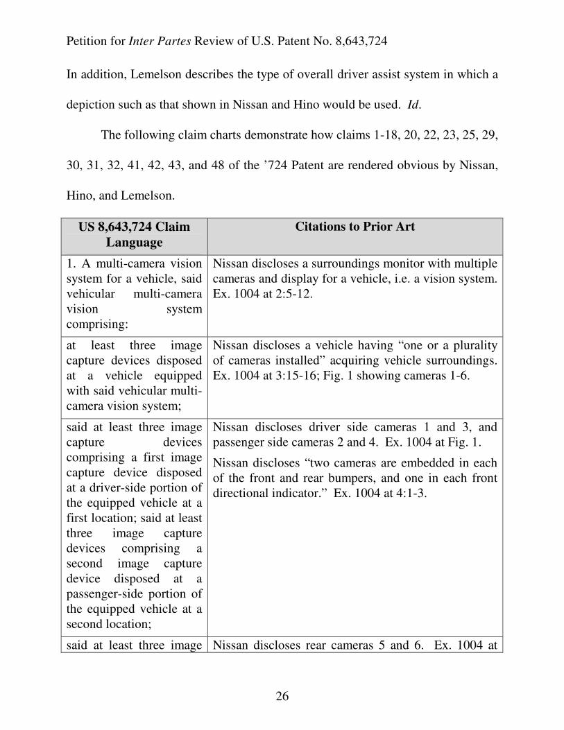
The following claim charts demonstrate how claims 1-18, 20, 22, 23, 25, 29,
30, 31, 32, 41, 42, 43, and 48 of the ’724 Patent are rendered obvious by Nissan,
Hino, and Lemelson.
US 8,643,724 Claim
Language
Citations to Prior Art
1. A multi-camera vision system for a vehicle, said vehicular multi-camera vision system comprising:
Nissan discloses a surroundings monitor with multiple cameras and display for a vehicle, i.e. a vision system. Ex. 1004 at 2:5-12.
at least three image capture devices disposed at a vehicle equipped with said vehicular multi-camera vision system;
Nissan discloses a vehicle having “one or a plurality of cameras installed” acquiring vehicle surroundings. Ex. 1004 at 3:15-16; Fig. 1 showing cameras 1-6.
said at least three image capture devices comprising a first image capture device disposed at a driver-side portion of the equipped vehicle at a first location; said at least three image capture devices comprising a second image capture device disposed at a passenger-side portion of the equipped vehicle at a second location;
Nissan discloses driver side cameras 1 and 3, and passenger side cameras 2 and 4. Ex. 1004 at Fig. 1.
Nissan discloses “two cameras are embedded in each of the front and rear bumpers, and one in each front directional indicator.” Ex. 1004 at 4:1-3.
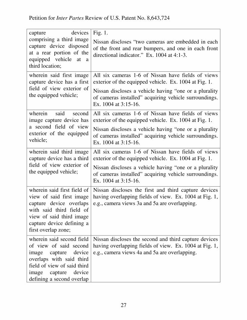
said at least three image Nissan discloses rear cameras 5 and 6. Ex. 1004 at
Petition for Inter Partes Review of U.S. Patent No. 8,643,724
27
capture devices comprising a third image capture device disposed at a rear portion of the equipped vehicle at a third location;
Fig. 1.
Nissan discloses “two cameras are embedded in each of the front and rear bumpers, and one in each front directional indicator.” Ex. 1004 at 4:1-3.
wherein said first image capture device has a first field of view exterior of the equipped vehicle;
All six cameras 1-6 of Nissan have fields of views exterior of the equipped vehicle. Ex. 1004 at Fig. 1.
Nissan discloses a vehicle having “one or a plurality of cameras installed” acquiring vehicle surroundings. Ex. 1004 at 3:15-16.
wherein said second image capture device has a second field of view exterior of the equipped vehicle;
All six cameras 1-6 of Nissan have fields of views exterior of the equipped vehicle. Ex. 1004 at Fig. 1.
Nissan discloses a vehicle having “one or a plurality of cameras installed” acquiring vehicle surroundings. Ex. 1004 at 3:15-16.
wherein said third image capture device has a third field of view exterior of the equipped vehicle;
All six cameras 1-6 of Nissan have fields of views exterior of the equipped vehicle. Ex. 1004 at Fig. 1.
Nissan discloses a vehicle having “one or a plurality of cameras installed” acquiring vehicle surroundings. Ex. 1004 at 3:15-16.
wherein said first field of view of said first image capture device overlaps with said third field of view of said third image capture device defining a first overlap zone;
Nissan discloses the first and third capture devices having overlapping fields of view. Ex. 1004 at Fig. 1, e.g., camera views 3a and 5a are overlapping.
wherein said second field of view of said second image capture device overlaps with said third field of view of said third image capture device defining a second overlap
Nissan discloses the second and third capture devices having overlapping fields of view. Ex. 1004 at Fig. 1, e.g., camera views 4a and 5a are overlapping.
Petition for Inter Partes Review of U.S. Patent No. 8,643,724
28
zone;
wherein said first image capture device captures first image data;
Each image capture device in Nissan captures image data. “…images captured by the cameras…” Ex. 1004 at 4:14.
wherein said second image capture device captures second image data;
Each image capture device in Nissan captures image data. “…images captured by the cameras…” Ex. 1004 at 4:14.
wherein said third image capture device captures third image data;
Each image capture device in Nissan captures image data. “…images captured by the cameras…” Ex. 1004 at 4:14.
an image processor; Nissan discloses “processor capable of … processing of the images,” and an image converter having an internal high-speed processor capable of parallel processing of the images of only N cameras. Ex. 1004 at 4:20-22.
wherein first image data captured by said first image capture device is received at said image processor via at least one of an analog data stream and a digital data stream;
Nissan discloses receiving first image data at the processor.
In Nissan, an image converter 7 having an internal high-speed processor capable of parallel processing of the images of only N cameras receives the images from cameras 1 to N. Ex. 1004 at 4:14-22.
Lemelson illustrates that an A/D converter 18 converts the data captured by the camera to digital form, before the data reaches the video preprocessor. Ex. 1002 at Figs. 1 and 2;
Lemelson discloses that the “analog signal output of camera 16 is digitized in an A/D convertor 18 and passed directly to or through a video preprocessor 51 to microprocessor 11.” Ex. 1002 at 5:38-40; 6:30-33.
wherein second image data captured by said second image capture device is received at said image processor via at
See above limitation.
Petition for Inter Partes Review of U.S. Patent No. 8,643,724
29
least one of an analog data stream and a digital data stream;
wherein third image data captured by said third image capture device is received at said image processor via at least one of an analog data stream and a digital data stream;
See above limitation.
wherein, responsive to processing by said image processor of received image data, a synthesized image is generated without duplication of objects present in said first overlap zone and in said second overlap zone and
Nissan discloses that the images captured by the plurality of cameras are synthesized. Ex. 1004 at Fig. 4, element DD “image synthesis.”
Nissan discloses means for combining images from multiple cameras into one image, i.e., synthesized image.
An image display unit for converting and combining the images from cameras 1 to N into one image. Ex. 1004 at 4:15-18.
Nissan performs a perspective transformation to bring all the images into a single coordinate system, from the independent screen coordinates of the cameras to the road surface plane. Ex. 1004 at 5:12-30.
wherein said synthesized image approximates a view as would be seen by a virtual camera at a single location exterior of the equipped vehicle;
Nissan performs a perspective transformation to bring all the images into a single coordinate system, from the independent screen coordinates of the cameras to the road surface plane. Ex. 1004 at 5:12-30. Figs. 3b and 3c of Nissan shows a bird’s eye view perspective from a virtual location directly above the vehicle.
Hino discloses that the view displayed to the driver depicts the peripheral conditions of the vehicle as seen from a single virtual location directly above the vehicle. Ex. 1008 at 4:31-37 and Fig. 3.
and wherein said synthesized image is displayed by a single
Nissan discloses “a display for displaying said image to the occupants.” Ex. 1004 at 3:20-21.
Petition for Inter Partes Review of U.S. Patent No. 8,643,724
30
display screen of a reconfigurable display device that is viewable by a driver of the equipped vehicle when normally operating the equipped vehicle.
Nissan discloses that the display is viewable while normally operating the vehicle. The image is “synthesized” according to element DD of Fig. 4 and obtained by combining images 1 to N into one image that is displayed to the vehicle occupants on a single TV monitor 9. Ex. 1004 at 4:15-20; 6:34-7:1.
Lemelson discloses a reconfigurable display device.
Actual image data can be displayed in real time using video display 55 via analog-to-digital converter 54. The image display may include highlighting of hazards, special warning images such as flashing lights, alpha-numeric messages, distance values, speed indicators and other hazard and safety related messages. Simulated displays of symbols representing the hazard objects as well as actual video displays may also be used to enhance driver recognition of dangerous situations.
Ex. 1002 at 6:46-54.
In a modified form of the invention, it is noted that system 10 may also perform as a navigational computer informing the driver of the motor vehicle containing same of the location of the vehicle by controlling the display 32 to cause it to display characters describing such location and/or a map showing the road or street along which the vehicle is travelling and its location and direction of travel there along by means of an indicia such as an arrow. The map may graphically or by means of characters include auxiliary information…
Ex. 1002 at 15:45-54.
Lemelson (Ex. 1002 at 16:11-19) discloses a reconfigurable display having user-selectable features.
A keyboard 82 and/or microphone (located, for
Petition for Inter Partes Review of U.S. Patent No. 8,643,724
31
example, in the steering wheel or steering wheel hub) of the vehicle and a speech
recognition computer such as computer 25 may be employed by the driver to generate command control signals for controlling the trip or navigational computer and effecting the display and/or playback of synthetic speech of select information on the location, direction of travel, distances to select locations, towns or cities, map information or other information as defined above.
In addition to the above-identified disclosures in Nissan, because of what
was known in the art about perspective transformation at the time, the PHOSITA
reading Nissan would have known that the perspective transformation and
averaging of pixel density described in Nissan was intended to bring multiple
images into geometric alignment for the purpose of removing duplication among
the images captured by the cameras. Ex. 1019 at ¶¶ 100-106. This removal of
duplication is what is described in the limitation “without duplication of objects
present in said first overlap zone and in said second overlap zone.” Id.
Accordingly, this limitation is obvious in view of Nissan. Id.
The synthesized image produced in Nissan is consistent with an image
produced from a single virtual location that is directly above the vehicle. The
perspective transformation mapping the image pixels of the camera to the road
plane in Nissan mimics a view from a single location, i.e., a bird’s eye view
directly above the vehicle, as shown in Figs. 3b and 3c of Nissan. Ex. 1019 at ¶¶
Petition for Inter Partes Review of U.S. Patent No. 8,643,724
32
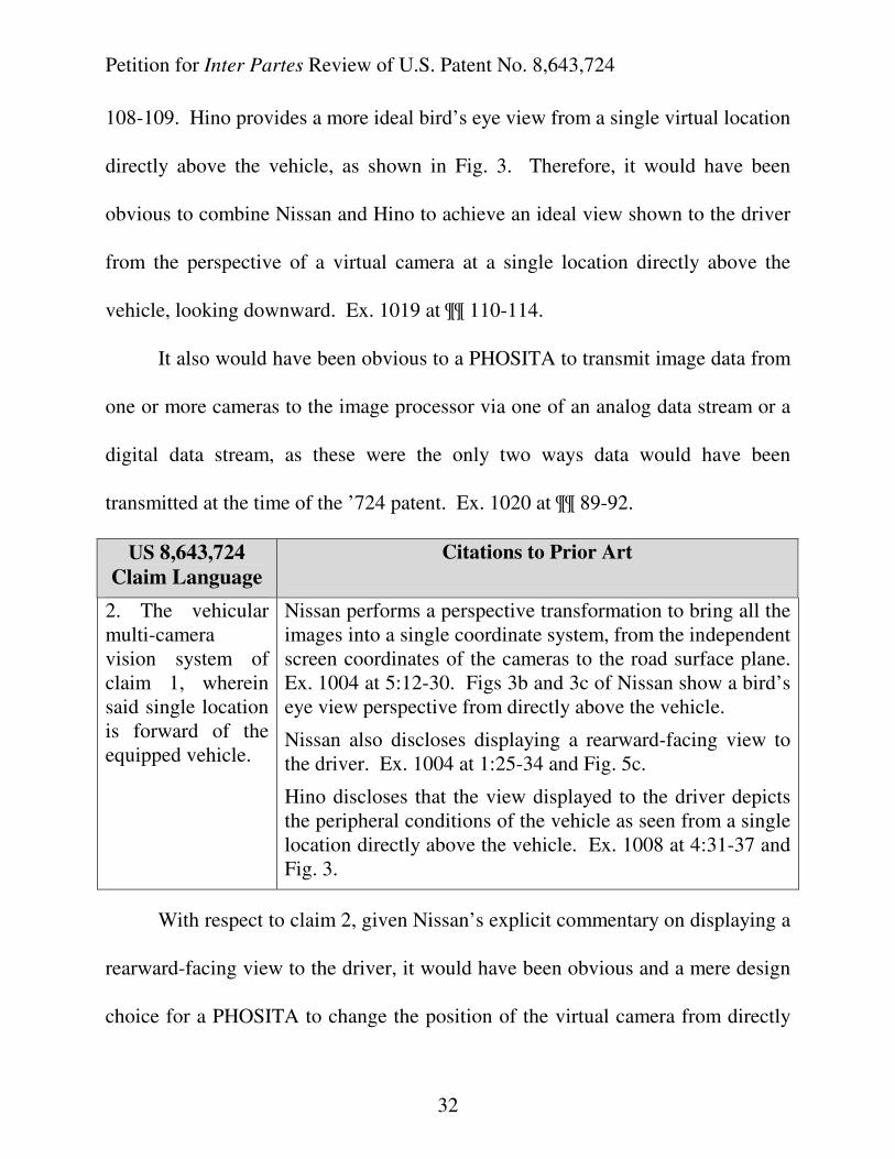
108-109. Hino provides a more ideal bird’s eye view from a single virtual location
directly above the vehicle, as shown in Fig. 3. Therefore, it would have been
obvious to combine Nissan and Hino to achieve an ideal view shown to the driver
from the perspective of a virtual camera at a single location directly above the
vehicle, looking downward. Ex. 1019 at ¶¶ 110-114.
It also would have been obvious to a PHOSITA to transmit image data from
one or more cameras to the image processor via one of an analog data stream or a
digital data stream, as these were the only two ways data would have been
transmitted at the time of the ’724 patent. Ex. 1020 at ¶¶ 89-92.
US 8,643,724
Claim Language
Citations to Prior Art
2. The vehicular multi-camera vision system of claim 1, wherein said single location is forward of the equipped vehicle.
Nissan performs a perspective transformation to bring all the images into a single coordinate system, from the independent screen coordinates of the cameras to the road surface plane. Ex. 1004 at 5:12-30. Figs 3b and 3c of Nissan show a bird’s eye view perspective from directly above the vehicle.
Nissan also discloses displaying a rearward-facing view to the driver. Ex. 1004 at 1:25-34 and Fig. 5c.
Hino discloses that the view displayed to the driver depicts the peripheral conditions of the vehicle as seen from a single location directly above the vehicle. Ex. 1008 at 4:31-37 and Fig. 3.
With respect to claim 2, given Nissan’s explicit commentary on displaying a
rearward-facing view to the driver, it would have been obvious and a mere design
choice for a PHOSITA to change the position of the virtual camera from directly
Petition for Inter Partes Review of U.S. Patent No. 8,643,724
33
above the vehicle to a position that is forward of the equipped vehicle, looking
rearward. Ex. 1019 at ¶¶ 115-116. To a PHOSITA, the equations in Nissan that
illustrate performing perspective transformation to obtain a plan view from the
perspective of a virtual camera directly above the equipped vehicle would have
been readily applicable to obtaining synthesized images from other perspectives,
such as forward of the equipped vehicle, looking rearward. Id. at ¶¶ 117-118.
US 8,643,724 Claim Language Citations to Prior Art
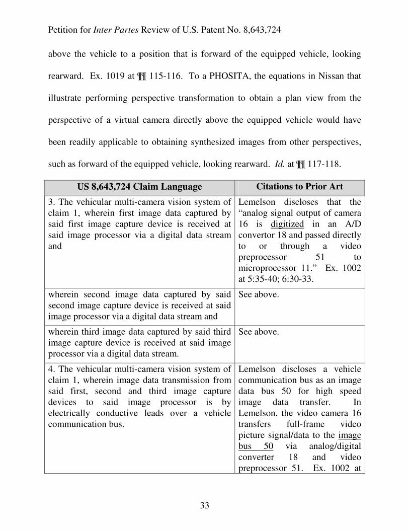
3. The vehicular multi-camera vision system of claim 1, wherein first image data captured by said first image capture device is received at said image processor via a digital data stream and
Lemelson discloses that the “analog signal output of camera 16 is digitized in an A/D convertor 18 and passed directly to or through a video preprocessor 51 to microprocessor 11.” Ex. 1002 at 5:35-40; 6:30-33.
wherein second image data captured by said second image capture device is received at said image processor via a digital data stream and
See above.
wherein third image data captured by said third image capture device is received at said image processor via a digital data stream.
See above.
4. The vehicular multi-camera vision system of claim 1, wherein image data transmission from said first, second and third image capture devices to said image processor is by electrically conductive leads over a vehicle communication bus.
Lemelson discloses a vehicle communication bus as an image data bus 50 for high speed image data transfer. In Lemelson, the video camera 16 transfers full-frame video picture signal/data to the image bus 50 via analog/digital converter 18 and video preprocessor 51. Ex. 1002 at
Petition for Inter Partes Review of U.S. Patent No. 8,643,724
34
6:26-33.
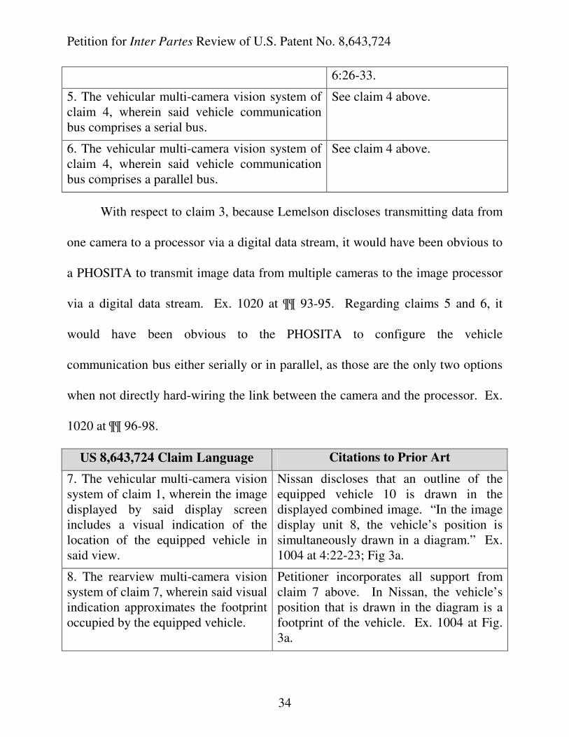
5. The vehicular multi-camera vision system of claim 4, wherein said vehicle communication bus comprises a serial bus.
See claim 4 above.
6. The vehicular multi-camera vision system of claim 4, wherein said vehicle communication bus comprises a parallel bus.
See claim 4 above.
With respect to claim 3, because Lemelson discloses transmitting data from
one camera to a processor via a digital data stream, it would have been obvious to
a PHOSITA to transmit image data from multiple cameras to the image processor
via a digital data stream. Ex. 1020 at ¶¶ 93-95. Regarding claims 5 and 6, it
would have been obvious to the PHOSITA to configure the vehicle
communication bus either serially or in parallel, as those are the only two options
when not directly hard-wiring the link between the camera and the processor. Ex.
1020 at ¶¶ 96-98.
US 8,643,724 Claim Language Citations to Prior Art
7. The vehicular multi-camera vision system of claim 1, wherein the image displayed by said display screen includes a visual indication of the location of the equipped vehicle in said view.
Nissan discloses that an outline of the equipped vehicle 10 is drawn in the displayed combined image. “In the image display unit 8, the vehicle’s position is simultaneously drawn in a diagram.” Ex. 1004 at 4:22-23; Fig 3a.
8. The rearview multi-camera vision system of claim 7, wherein said visual indication approximates the footprint occupied by the equipped vehicle.
Petitioner incorporates all support from claim 7 above. In Nissan, the vehicle’s position that is drawn in the diagram is a footprint of the vehicle. Ex. 1004 at Fig. 3a.
Petition for Inter Partes Review of U.S. Patent No. 8,643,724
35
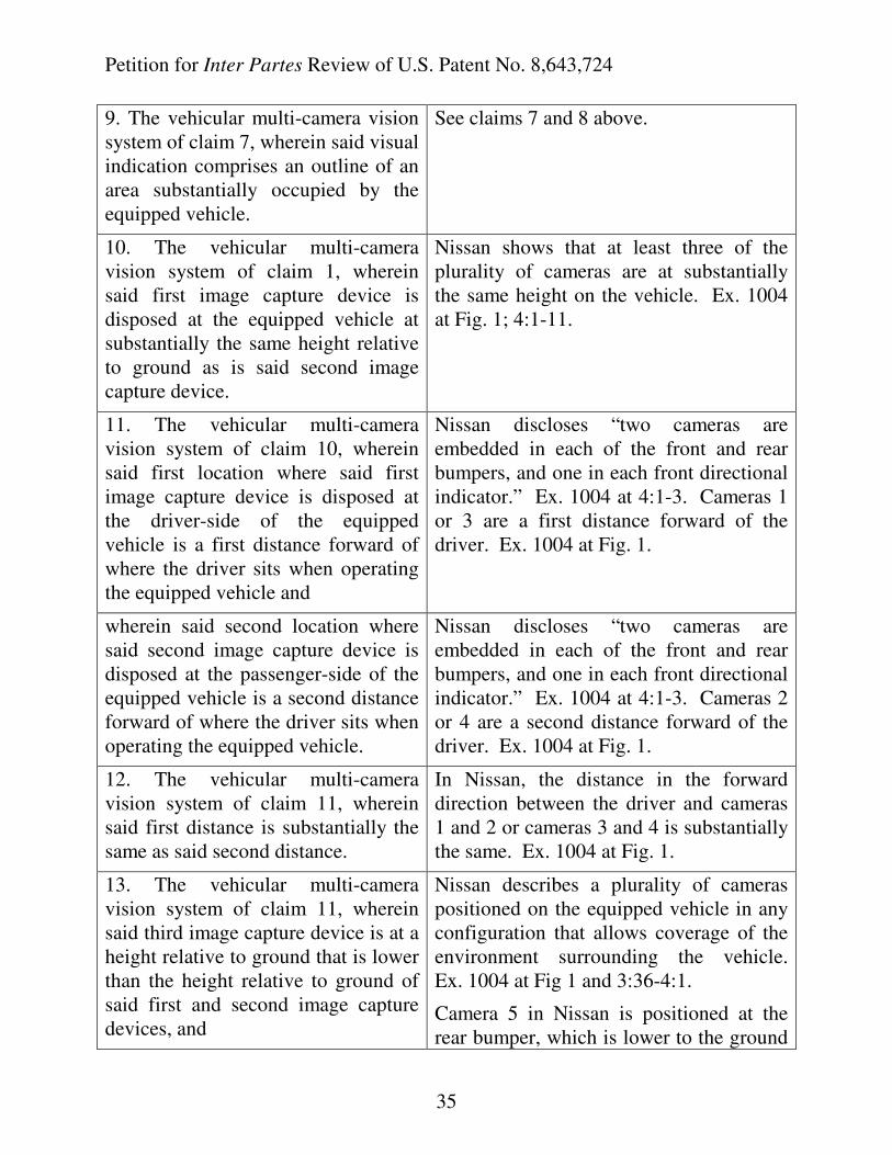
9. The vehicular multi-camera vision system of claim 7, wherein said visual indication comprises an outline of an area substantially occupied by the equipped vehicle.
See claims 7 and 8 above.
10. The vehicular multi-camera vision system of claim 1, wherein said first image capture device is disposed at the equipped vehicle at substantially the same height relative to ground as is said second image capture device.
Nissan shows that at least three of the plurality of cameras are at substantially the same height on the vehicle. Ex. 1004 at Fig. 1; 4:1-11.
11. The vehicular multi-camera vision system of claim 10, wherein said first location where said first image capture device is disposed at the driver-side of the equipped vehicle is a first distance forward of where the driver sits when operating the equipped vehicle and
Nissan discloses “two cameras are embedded in each of the front and rear bumpers, and one in each front directional indicator.” Ex. 1004 at 4:1-3. Cameras 1 or 3 are a first distance forward of the driver. Ex. 1004 at Fig. 1.
wherein said second location where said second image capture device is disposed at the passenger-side of the equipped vehicle is a second distance forward of where the driver sits when operating the equipped vehicle.
Nissan discloses “two cameras are embedded in each of the front and rear bumpers, and one in each front directional indicator.” Ex. 1004 at 4:1-3. Cameras 2 or 4 are a second distance forward of the driver. Ex. 1004 at Fig. 1.
12. The vehicular multi-camera vision system of claim 11, wherein said first distance is substantially the same as said second distance.
In Nissan, the distance in the forward direction between the driver and cameras 1 and 2 or cameras 3 and 4 is substantially the same. Ex. 1004 at Fig. 1.
13. The vehicular multi-camera vision system of claim 11, wherein said third image capture device is at a height relative to ground that is lower than the height relative to ground of said first and second image capture devices, and
Nissan describes a plurality of cameras positioned on the equipped vehicle in any configuration that allows coverage of the environment surrounding the vehicle. Ex. 1004 at Fig 1 and 3:36-4:1.
Camera 5 in Nissan is positioned at the rear bumper, which is lower to the ground
Petition for Inter Partes Review of U.S. Patent No. 8,643,724
36
than cameras 3, 4, at the directional indicators. Ex. 1004 at 4:1-3.
wherein said third location is a third distance rearward of where the driver sits when operating the equipped vehicle,
Nissan discloses a camera at a rear portion of the vehicle, rearward of where the driver sits. (Ex. 1004 at Fig. 1, camera 5).
wherein said third distance is larger than either of said first and second distances.
In Nissan, the rearward distance between the driver’s position and camera 5 is greater than the distance between the driver’s position and cameras 3, 4. Ex. 1004 at Fig. 1.
With respect to claim 13, Nissan explicitly comments that the number of
cameras does not matter. Ex. 1004 at 1:20-23. Further, Nissan states that the
cameras may be positioned to “cover the environment surrounding the vehicle as
much as possible.” Ex. 1004 at 3:36-4:1. It would have been obvious to a
PHOSITA that the rearward distance between the driver and various cameras
mounted on the vehicle would be dependent on the body style of the equipped
vehicle, and would be a mere design choice. It also would have been a matter of
common sense, and, therefore obvious to the PHOSITA, that the distance between
the driver and cameras at the rear of the vehicle would be greater than the distance
to cameras at the side and/or front of the vehicle. Ex. 1019 at 125-131.
US 8,643,724 Claim Language Citations to Prior Art
14. The vehicular multi-camera vision system of claim 1, wherein said at least three image capture devices have the principal axis of
Nissan discloses front, side and rear image capture devices, which are aimed along non-parallel axes. The axes of the rear cameras 5, 6 are not parallel to those of
Petition for Inter Partes Review of U.S. Patent No. 8,643,724
37
their respective field of view aimed along non-parallel axes.
the side cameras 3, 4. Ex. 1004 at Fig. 1.
15. The vehicular multi-camera vision system of claim 1, wherein the image displayed by said display screen approximates a rearward-facing view from a single location exterior of the equipped vehicle.
Petitioner incorporates all support from claim 2 above.
Nissan discloses displaying a rearward-facing view to the driver from rearward of the vehicle. Ex. 1004 2:25-34 at and Fig. 5c.
16. The vehicular multi-camera vision system of claim 15, wherein said single location is forward of the equipped vehicle.
Petitioner incorporates all support from claims 2 and 15, above.
With respect to claims 15 and 16, in addition to the above-identified Nissan
disclosure, because drivers, as a matter of common sense, have always been
interested in views to the rear of the vehicle, a PHOSITA would have found it
obvious to show a rearward facing view rather than, or in addition to, a bird’s eye
view in Nissan, resulting in a combined view forward of the driver, looking
rearward. Ex. 1019 at ¶¶117-118; 121.
US 8,643,724 Claim
Language
Citations to Prior Art
17. The vehicular multi-camera vision system of claim 1, wherein a fourth image capture device is disposed at a front portion of the equipped vehicle.
Nissan discloses a vehicle having “one or a plurality of cameras installed” acquiring vehicle surroundings. Ex. 1004 at 3:15-16; Fig. 1 showing cameras 1-6.
Nissan discloses:
“...two cameras are embedded in each of the front and rear bumpers, and one in each front directional indicator.” Ex. 1004 at 4:1-3.
18. The vehicular multi-camera Petitioner incorporates all support from claims
Petition for Inter Partes Review of U.S. Patent No. 8,643,724
38
vision system of claim 17, wherein said single location is rearward of the equipped vehicle.
2, 16, and 17 above.
20. The vehicular multi-camera vision system of claim 1, wherein the image displayed by said display screen comprises a graphic overlay.
Nissan discloses maneuvering rearwardly using the vision system. Ex. 1004 at 7:32. Nissan also discloses an overlay of the vehicle image 10 drawn on the display, superimposed on the synthesized image. Ex. 1004 at 4:22-23; Fig. 3.
Lemelson also discloses graphically overlaying information onto the displayed image.
The image display may include highlighting of hazards, special warning images such as flashing lights, alpha-numeric messages, distance values, speed indicators and other hazard and safety related messages. Simulated displays of symbols representing the hazard objects as well as actual video displays may also be used to enhance driver recognition of dangerous situations.
Ex. 1002 at 6:49-55.
22. The vehicular multi-camera vision system of claim 20, wherein said graphic overlay comprises indicia indicating distance to objects exterior the equipped vehicle.
Lemelson discloses overlaying distance to objects on the displayed image.
The image display may include highlighting of hazards, special warning images such as flashing lights, alpha-numeric messages, distance values, speed indicators and other hazard and safety related messages. Simulated displays of symbols representing the hazard objects as well as actual video displays may also be used to enhance driver recognition of dangerous situations.
Ex. 1002 at 6:49-55.
Distance values are described in Lemelson
Petition for Inter Partes Review of U.S. Patent No. 8,643,724
39
as distance to objects exterior of the vehicle.
The preferred form of the invention provides audible and/or visual display means to cooperate in indicating to the driver of a motor vehicle both normal and hazardous road conditions ahead as well as driving variables such as distances to stationary objects, and other vehicles; the identification, direction of travel and speed of such other vehicles, and the identification of and distances to stationary or slowly moving objects such as barriers, center islands, pedestrians, parked cars poles, sharp turns in the road and other conditions.
Ex. 1002 at 2:23-32.
23. The vehicular multi-camera vision system of claim 1, wherein the image displayed by said display screen comprises enhancements that assist visually distinguishing objects close to the equipped vehicle.
Lemelson discloses visually distinguishing objects with color and flashing lights:
When the closing distance becomes hazardous, select vehicle subsystems may be automatically controlled by the computer as it continues to analyze image signals generated by the television camera. A first subsystem generates a first select code or codes which control an electronic display, such as a heads-up display to cause it to display a warning indication, such as one or more flashing red light portions of the display or other lighted effect. For example, the display may project on the windshield or dashboard such information as images of the controlled vehicle and other vehicles in and adjacent its path of travel and relative distances thereto as well as groups of characters defining same, colored and flashing warning lights and
Petition for Inter Partes Review of U.S. Patent No. 8,643,724
40
the like for pre-warning and warning purposes.
Ex. 1002 at 2:50-63.
25. The vehicular multi-camera vision system of claim 1, wherein at least one of color and flashing is used to draw the driver's attention to a potential hazard present in the image displayed by said display screen.
See claim 23 above.
29. The vehicular multi-camera vision system of claim 1, wherein said display screen of said reconfigurable display device is operable to display at least one of …
Lemelson discloses a reconfigurable display device for displaying auxiliary information. Ex. 1002 at 6:48-54; 15:45-57.
…(iv)4 a map… Lemelson discloses displaying a map:
In a modified form of the invention, it is noted that system 10 may also perform as a navigational computer informing the driver of the motor vehicle containing same of the location of the vehicle by
4 For readability and to avoid confusion, alternatives not challenged are not recited
in the claim charts, but instead are denoted with ellipses (“…”). For example, for
claim 29, only alternative (iv) is challenged; accordingly, alternatives (i)-(iii)
recited by claim 29 before alternative (iv) are denoted by the ellipses before the
listed alternative (iv) and alternatives (v)-(xii) recited by claim 29 after alternative
(iv) are denoted by the ellipses after the listed alternative (iv).
Petition for Inter Partes Review of U.S. Patent No. 8,643,724
41
controlling the display 32 to cause it to display characters describing such location and/or a map showing the road or street along which the vehicle is travelling and its location and direction of travel there along by means of an indicia such as an arrow. The map may graphically or by means of characters include auxiliary information…
Ex. 1002 at 15:45-54.
30. The vehicular multi-camera vision system of claim 1, wherein content displayed by said display screen of said reconfigurable display device is user-selectable.
Lemelson discloses that the driver can select what the display shows:
A keyboard 82 and/or microphone (located, for example, in the steering wheel or steering wheel hub) of the vehicle and a speech recognition computer such as computer 25 may be employed by the driver to generate command control signals for controlling the trip or navigational computer and effecting the display and/or playback of synthetic speech of select information on the location, direction of travel, distances to select locations, towns or cities, map information or other information as defined above.
Ex. 1002 at 16:11-19.
31. The vehicular multi-camera vision system of claim 1, wherein content displayed by said display screen of said reconfigurable display device is user-selectable via at least one of a keypad and a trackball.
See claim 30 above. Lemelson discloses a keyboard (keypad) is employed by the driver to effect the display. Ex. 1002 at 16:11-19.
32. The vehicular multi-camera vision system of claim 1, wherein content displayed by
See claim 30 above. Lemelson discloses that the input devices for the driver are located at the steering wheel or steering wheel hub. Ex. 1002
Petition for Inter Partes Review of U.S. Patent No. 8,643,724
42
said display screen of said reconfigurable display device is user-selectable via an input device located at a steering column of the equipped vehicle or at a dashboard of the equipped vehicle.
at 16:11-19.
41. The vehicular multi-camera vision system of claim 1, wherein at least one of…
See claim 1. Nissan discloses a multi-camera vision system. Ex. 1004 at 2:5-12.
…(c) said vehicular multi-camera vision system provides accident monitoring…
Nissan discloses that the vision system enable easy recognition of relative positions of obstructions, the other vehicles surrounding the vehicle, and the center line to the vehicle itself. Ex. 1004 at 7:20-24.
Lemelson discloses “[A] system and method assists the driver of a motor vehicle in preventing accidents or minimizing the effects of same.” Ex. 1002 at Abstract and 1:10-16.
Lemelson also discloses a separate driver monitoring computer to constantly monitor driver actions and reactions while operating the vehicle:
[D]riving patterns inconsistent with surrounding vehicle motion can be detected such as any action by the driver that increases rather than decreases the possibility of a collision in a dangerous or hazardous situation. A separate driver monitoring system can detect all of these situations and respond by warning the driver or, if necessary, activating the automated vehicle control system.
Ex. 1002 at 17:51-58.
42. The vehicular multi-camera vision system of claim 1,
Nissan discloses cameras 3 and 4, which have fields of views 3a, 4a bound by the side of the
Petition for Inter Partes Review of U.S. Patent No. 8,643,724
43
wherein said first field of view said first image capture device is bounded by the side of the equipped vehicle it is disposed at and extends outwards therefrom.
equipped vehicle and extend outward therefrom. Ex. 1004 at Fig. 1.
43. The vehicular multi-camera vision system of claim 1, wherein said second field of view said second image capture device is bounded by the side of the equipped vehicle it is disposed at and extends outwards therefrom.
Nissan discloses cameras 3 and 4, which have fields of views 3a, 4a bound by the side of the equipped vehicle and extend outward therefrom. Ex. 1004 at Fig. 1.
48. The vehicular multi-camera vision system of claim 1, wherein said synthesized image displayed by said display screen approximates a substantially seamless view as would be viewed from a single virtual camera located exterior the equipped vehicle.
Nissan discloses a synthesized image. Ex. 1004 at 4:15-18. Nissan also discloses a seamless view without borders or delineations from a bird’s eye perspective in Figs. 3a-3c.
Hino discloses a seamless view displayed to the driver which depicts the peripheral conditions of the vehicle as seen from a single location directly above the vehicle. Ex. 1008 at 4:31-37 and Fig. 3; 5:8-10.
B. Claim 19 of the ‘724 Patent is obvious over Nissan, Hino,
Lemelson, and Wang.
Claim 19 is obvious over Nissan, Hino, Lemelson, and Wang. For a
technical description of Wang, see Ex. 1019 at ¶¶ 36, 83-85.
A PHOSITA would have been motivated to combine Nissan and Wang (Ex.
1009) because Nissan says that any suitable camera for capturing a vehicle’s
surroundings may be employed in the vision system of Nissan. Ex. 1004 at 2:22.
Lemelson discloses the use of CCD cameras. Ex. 1002 at 6:30-33. Wang employs
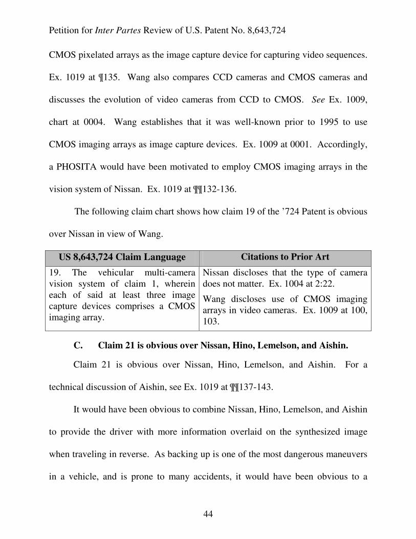
Petition for Inter Partes Review of U.S. Patent No. 8,643,724
44
CMOS pixelated arrays as the image capture device for capturing video sequences.
Ex. 1019 at ¶135. Wang also compares CCD cameras and CMOS cameras and
discusses the evolution of video cameras from CCD to CMOS. See Ex. 1009,
chart at 0004. Wang establishes that it was well-known prior to 1995 to use
CMOS imaging arrays as image capture devices. Ex. 1009 at 0001. Accordingly,
a PHOSITA would have been motivated to employ CMOS imaging arrays in the
vision system of Nissan. Ex. 1019 at ¶¶132-136.
The following claim chart shows how claim 19 of the ’724 Patent is obvious
over Nissan in view of Wang.
US 8,643,724 Claim Language Citations to Prior Art
19. The vehicular multi-camera vision system of claim 1, wherein each of said at least three image capture devices comprises a CMOS imaging array.
Nissan discloses that the type of camera does not matter. Ex. 1004 at 2:22.
Wang discloses use of CMOS imaging arrays in video cameras. Ex. 1009 at 100, 103.
C. Claim 21 is obvious over Nissan, Hino, Lemelson, and Aishin.
Claim 21 is obvious over Nissan, Hino, Lemelson, and Aishin. For a
technical discussion of Aishin, see Ex. 1019 at ¶¶137-143.
It would have been obvious to combine Nissan, Hino, Lemelson, and Aishin
to provide the driver with more information overlaid on the synthesized image
when traveling in reverse. As backing up is one of the most dangerous maneuvers
in a vehicle, and is prone to many accidents, it would have been obvious to a
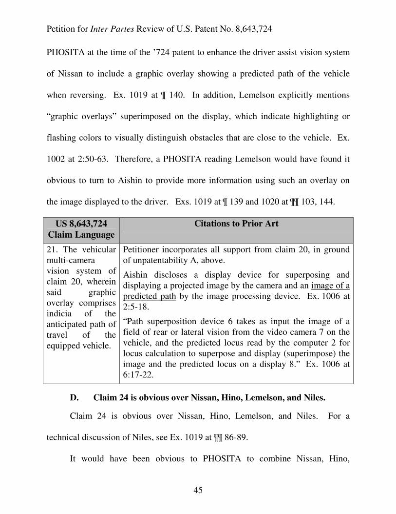
Petition for Inter Partes Review of U.S. Patent No. 8,643,724
45
PHOSITA at the time of the ’724 patent to enhance the driver assist vision system
of Nissan to include a graphic overlay showing a predicted path of the vehicle
when reversing. Ex. 1019 at ¶ 140. In addition, Lemelson explicitly mentions
“graphic overlays” superimposed on the display, which indicate highlighting or
flashing colors to visually distinguish obstacles that are close to the vehicle. Ex.
1002 at 2:50-63. Therefore, a PHOSITA reading Lemelson would have found it
obvious to turn to Aishin to provide more information using such an overlay on
the image displayed to the driver. Exs. 1019 at ¶ 139 and 1020 at ¶¶ 103, 144.
US 8,643,724
Claim Language
Citations to Prior Art
21. The vehicular multi-camera vision system of claim 20, wherein said graphic overlay comprises indicia of the anticipated path of travel of the equipped vehicle.
Petitioner incorporates all support from claim 20, in ground of unpatentability A, above.
Aishin discloses a display device for superposing and displaying a projected image by the camera and an image of a predicted path by the image processing device. Ex. 1006 at 2:5-18.
“Path superposition device 6 takes as input the image of a field of rear or lateral vision from the video camera 7 on the vehicle, and the predicted locus read by the computer 2 for locus calculation to superpose and display (superimpose) the image and the predicted locus on a display 8.” Ex. 1006 at 6:17-22.
D. Claim 24 is obvious over Nissan, Hino, Lemelson, and Niles.
Claim 24 is obvious over Nissan, Hino, Lemelson, and Niles. For a
technical discussion of Niles, see Ex. 1019 at ¶¶ 86-89.
It would have been obvious to PHOSITA to combine Nissan, Hino,
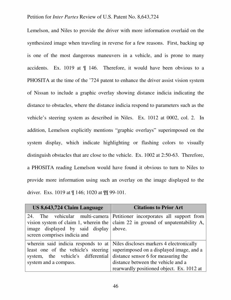
Petition for Inter Partes Review of U.S. Patent No. 8,643,724
46
Lemelson, and Niles to provide the driver with more information overlaid on the
synthesized image when traveling in reverse for a few reasons. First, backing up
is one of the most dangerous maneuvers in a vehicle, and is prone to many
accidents. Ex. 1019 at ¶ 146. Therefore, it would have been obvious to a
PHOSITA at the time of the ’724 patent to enhance the driver assist vision system
of Nissan to include a graphic overlay showing distance indicia indicating the
distance to obstacles, where the distance indicia respond to parameters such as the
vehicle’s steering system as described in Niles. Ex. 1012 at 0002, col. 2. In
addition, Lemelson explicitly mentions “graphic overlays” superimposed on the
system display, which indicate highlighting or flashing colors to visually
distinguish obstacles that are close to the vehicle. Ex. 1002 at 2:50-63. Therefore,
a PHOSITA reading Lemelson would have found it obvious to turn to Niles to
provide more information using such an overlay on the image displayed to the
driver. Exs. 1019 at ¶ 146; 1020 at ¶¶ 99-101.
US 8,643,724 Claim Language Citations to Prior Art
24. The vehicular multi-camera vision system of claim 1, wherein the image displayed by said display screen comprises indicia and
Petitioner incorporates all support from claim 22 in ground of unpatentability A, above.
wherein said indicia responds to at least one of the vehicle's steering system, the vehicle's differential system and a compass.
Niles discloses markers 4 electronically superimposed on a displayed image, and a distance sensor 6 for measuring the distance between the vehicle and a rearwardly positioned object. Ex. 1012 at
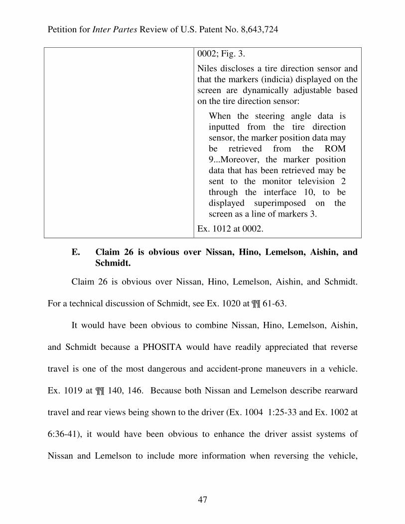
Petition for Inter Partes Review of U.S. Patent No. 8,643,724
47
0002; Fig. 3.
Niles discloses a tire direction sensor and that the markers (indicia) displayed on the screen are dynamically adjustable based on the tire direction sensor:
When the steering angle data is inputted from the tire direction sensor, the marker position data may be retrieved from the ROM 9...Moreover, the marker position data that has been retrieved may be sent to the monitor television 2 through the interface 10, to be displayed superimposed on the screen as a line of markers 3.
Ex. 1012 at 0002.
E. Claim 26 is obvious over Nissan, Hino, Lemelson, Aishin, and
Schmidt.
Claim 26 is obvious over Nissan, Hino, Lemelson, Aishin, and Schmidt.
For a technical discussion of Schmidt, see Ex. 1020 at ¶¶ 61-63.
It would have been obvious to combine Nissan, Hino, Lemelson, Aishin,
and Schmidt because a PHOSITA would have readily appreciated that reverse
travel is one of the most dangerous and accident-prone maneuvers in a vehicle.
Ex. 1019 at ¶¶ 140, 146. Because both Nissan and Lemelson describe rearward
travel and rear views being shown to the driver (Ex. 1004 1:25-33 and Ex. 1002 at
6:36-41), it would have been obvious to enhance the driver assist systems of
Nissan and Lemelson to include more information when reversing the vehicle,
Petition for Inter Partes Review of U.S. Patent No. 8,643,724
48
such as a predicted path of the vehicle, as described in Aishin. Ex. 1020 at ¶¶ 102-
105. As Schmidt is directed toward a multi-camera video recording and display
system for use in a passenger vehicle, it would have been obvious for a PHOSITA
to look to a reference that specifically addresses providing a means for viewing the
blind spots of a vehicle, means for deterring passengers inappropriate behavior
and motorists' unlawful behavior, as well as deterring vandalism. Ex. 1016 at
10:39-44.
Because Aishin explicitly notes that the predicted path of the vehicle is
displayed at the time of reverse travel, which requires the vehicle to be in reverse
gear, and Lemelson explicitly discloses such a wide variety of information that can
be presented to a driver at a given time when operating the vehicle, all of which
are important in minimizing collisions and assisting the driver in avoiding hazards,
it would have been obvious to disable certain information, such as the graphic
overlay of the predicted path of the vehicle, when the vehicle is not in reverse
gear. Ex. 1020 at ¶ 103.
US 8,643,724 Claim Language Citations to Prior Art
26. The vehicular multi-camera vision system of claim 1, wherein the image displayed by said display screen comprises a graphic overlay that includes indicia of the anticipated path of travel of the equipped vehicle and
Petitioner incorporates all support from claim 21 in ground of unpatentability C, above.
Petition for Inter Partes Review of U.S. Patent No. 8,643,724
49
wherein said graphic overlay is disabled when the vehicle's gear actuator is not in reverse gear.
Aishin discloses a graphic overlay: “…predicted path are displayed on a screen at the time of reverse travel of a vehicle.” Ex. 1006 at 4:17-19.
Schmidt discloses: “the system serves primarily as a means for displaying areas about the vehicle that are not normally viewable by the driver. As such, an additional circuit is supplied such that when a person puts the vehicle in "reverse", images received at the rear camera are automatically relayed to the display 34. It is well known to utilize the transmission of a vehicle as a switch and one skilled in the art is able to connect the rear camera to the display if the vehicle is placed in reverse.” Ex. 1016 at 9:16-26.
F. Claims 27 and 28 are obvious over Nissan, Hino, Lemelson, and
Fuji.
Claims 27 and 28 are obvious over Nissan, Hino, Lemelson, and Fuji. For a
technical discussion of Fuji, see Ex. 1020 at ¶¶ 49-52.
Lemelson discusses a system and method employing a television scanning
camera mounted on a vehicle for scanning the field ahead, such as the image of the
road ahead of the vehicle. Ex. 1002 at Abstract. The Lemelson system also
includes a computer for analyzing the image signals generated. Id. at Fig. 1. In
this system, automatic image intensifying means, or infra-red scanning and
detection means, are utilized to permit scanning operations to be effected during
driving at night and in low light, snowing or fog conditions. Id. at 4:8-15. A
Petition for Inter Partes Review of U.S. Patent No. 8,643,724
50
PHOSITA would have readily appreciated that the system of Lemelson was
designed to provide the driver with the maximum amount of useful information on
a reconfigurable display under all types of environmental conditions. It would
have been obvious to combine Nissan, Hino, Lemelson, and Fuji because a
PHOSITA would have readily appreciated that a reconfigurable display of any
type would only be useful if it was viewable to the driver at all times, i.e., in the
daytime and at night. Ex. 1020 at ¶¶ 106-111. Because a driver would need to
view the information on the display under all light conditions, it would have been
obvious to a PHOSITA to ensure that brightness (luminance) of the display would
be adaptable for the reconfigurable display to be viewable under all environmental
conditions. Id.
US 8,643,724 Claim Language Citations to Prior Art
27. The vehicular multi-camera vision system of claim 1, wherein the display luminance of said display screen of said reconfigurable display device is variable responsive to a sensing of an ambient light level.
Regarding the reconfigurable display, Petitioner incorporates all support from claim 1 in ground of unpatentability A, above.
Fuji discloses a display screen having a display luminance variably responsive to sensing of an ambient light level. Ex. 1010 at 7:25 – 8:25.
Fuji discloses sensing means for sensing ambient light levels outside of the vehicle and for producing corresponding output signals. Ex. 1010 at 2:19-21.
Fuji also discloses control circuits for controlling the image of the television set
Petition for Inter Partes Review of U.S. Patent No. 8,643,724
51
2, for displaying a rearward view of the vehicle, dependent on the light level outside of the vehicle. “The image on the display of the television set is automatically controlled in response to the intensity of the light outside the motor vehicle. Ex. 1010 at 8:5-25.
28. The vehicular multi-camera vision system of claim 1, wherein the display luminance of said display screen of said reconfigurable display device is variable responsive to at least one of …
Fuji discloses a display screen having a display luminance variably responsive to sensing of an ambient light level. Ex. 1010 at 7:25 – 8:25.
...(ii) an ambient light sensor… See claim 27 above. Ex. 1010 at 2:19-21.
G. Claims 33, 35, and 36-38 are obvious over Nissan, Hino,
Lemelson, and Otsuka.
Claims 33 and 35-38 are obvious over Nissan, Hino, Lemelson, and Otsuka.
For a technical discussion of Otsuka, see Ex. 1020 at ¶¶ 67-69.
Otsuka discloses various types of displays for use in a motor vehicle. Ex.
1017. Given that Nissan discloses a TV monitor as the display unit and Lemelson
discusses a reconfigurable video display capable of displaying a wide variety of
information in addition to a video camera image, it would have been obvious and a
mere design choice for a PHOSITA to implement a flat panel or other type of
display that takes up less space inside the vehicle and still provides a clear image
to the driver. Ex. 1020 at ¶¶ 112-116. It also would have been obvious to vary
and improve the interior design of a vehicle for different vehicle models and types,
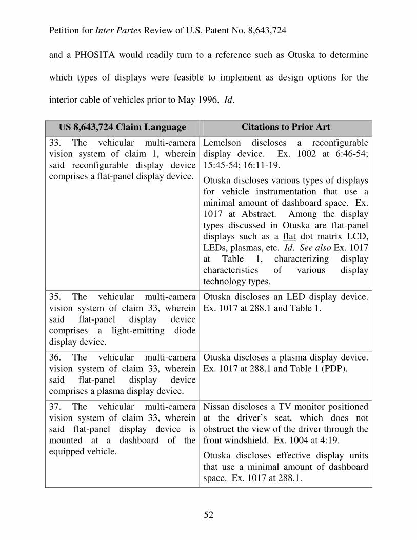
Petition for Inter Partes Review of U.S. Patent No. 8,643,724
52
and a PHOSITA would readily turn to a reference such as Otuska to determine
which types of displays were feasible to implement as design options for the
interior cable of vehicles prior to May 1996. Id.
US 8,643,724 Claim Language Citations to Prior Art
33. The vehicular multi-camera vision system of claim 1, wherein said reconfigurable display device comprises a flat-panel display device.
Lemelson discloses a reconfigurable display device. Ex. 1002 at 6:46-54; 15:45-54; 16:11-19.
Otuska discloses various types of displays for vehicle instrumentation that use a minimal amount of dashboard space. Ex. 1017 at Abstract. Among the display types discussed in Otuska are flat-panel displays such as a flat dot matrix LCD, LEDs, plasmas, etc. Id. See also Ex. 1017 at Table 1, characterizing display characteristics of various display technology types.
35. The vehicular multi-camera vision system of claim 33, wherein said flat-panel display device comprises a light-emitting diode display device.
Otuska discloses an LED display device. Ex. 1017 at 288.1 and Table 1.
36. The vehicular multi-camera vision system of claim 33, wherein said flat-panel display device comprises a plasma display device.
Otuska discloses a plasma display device. Ex. 1017 at 288.1 and Table 1 (PDP).
37. The vehicular multi-camera vision system of claim 33, wherein said flat-panel display device is mounted at a dashboard of the equipped vehicle.
Nissan discloses a TV monitor positioned at the driver’s seat, which does not obstruct the view of the driver through the front windshield. Ex. 1004 at 4:19.
Otuska discloses effective display units that use a minimal amount of dashboard space. Ex. 1017 at 288.1.
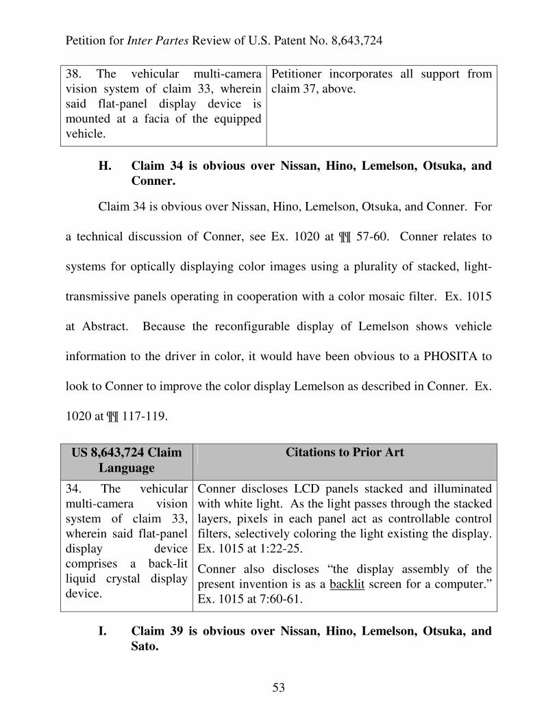
Petition for Inter Partes Review of U.S. Patent No. 8,643,724
53
38. The vehicular multi-camera vision system of claim 33, wherein said flat-panel display device is mounted at a facia of the equipped vehicle.
Petitioner incorporates all support from claim 37, above.
H. Claim 34 is obvious over Nissan, Hino, Lemelson, Otsuka, and
Conner.
Claim 34 is obvious over Nissan, Hino, Lemelson, Otsuka, and Conner. For
a technical discussion of Conner, see Ex. 1020 at ¶¶ 57-60. Conner relates to
systems for optically displaying color images using a plurality of stacked, light-
transmissive panels operating in cooperation with a color mosaic filter. Ex. 1015
at Abstract. Because the reconfigurable display of Lemelson shows vehicle
information to the driver in color, it would have been obvious to a PHOSITA to
look to Conner to improve the color display Lemelson as described in Conner. Ex.
1020 at ¶¶ 117-119.
US 8,643,724 Claim
Language
Citations to Prior Art
34. The vehicular multi-camera vision system of claim 33, wherein said flat-panel display device comprises a back-lit liquid crystal display device.
Conner discloses LCD panels stacked and illuminated with white light. As the light passes through the stacked layers, pixels in each panel act as controllable control filters, selectively coloring the light existing the display. Ex. 1015 at 1:22-25.
Conner also discloses “the display assembly of the present invention is as a backlit screen for a computer.” Ex. 1015 at 7:60-61.
I. Claim 39 is obvious over Nissan, Hino, Lemelson, Otsuka, and
Sato.
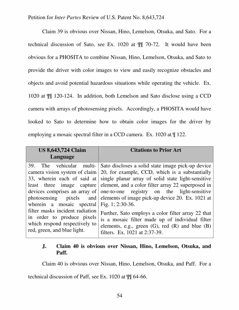
Petition for Inter Partes Review of U.S. Patent No. 8,643,724
54
Claim 39 is obvious over Nissan, Hino, Lemelson, Otsuka, and Sato. For a
technical discussion of Sato, see Ex. 1020 at ¶¶ 70-72. It would have been
obvious for a PHOSITA to combine Nissan, Hino, Lemelson, Otsuka, and Sato to
provide the driver with color images to view and easily recognize obstacles and
objects and avoid potential hazardous situations while operating the vehicle. Ex.
1020 at ¶¶ 120-124. In addition, both Lemelson and Sato disclose using a CCD
camera with arrays of photosensing pixels. Accordingly, a PHOSITA would have
looked to Sato to determine how to obtain color images for the driver by
employing a mosaic spectral filter in a CCD camera. Ex. 1020 at ¶ 122.
US 8,643,724 Claim
Language
Citations to Prior Art
39. The vehicular multi-camera vision system of claim 33, wherein each of said at least three image capture devices comprises an array of photosensing pixels and wherein a mosaic spectral filter masks incident radiation in order to produce pixels which respond respectively to red, green, and blue light.
Sato discloses a solid state image pick-up device 20, for example, CCD, which is a substantially single planar array of solid state light-sensitive element, and a color filter array 22 superposed in one-to-one registry on the light-sensitive elements of image pick-up device 20. Ex. 1021 at Fig. 1; 2:30-36.
Further, Sato employs a color filter array 22 that is a mosaic filter made up of individual filter elements, e.g., green (G), red (R) and blue (B) filters. Ex. 1021 at 2:37-39.
J. Claim 40 is obvious over Nissan, Hino, Lemelson, Otsuka, and
Paff.
Claim 40 is obvious over Nissan, Hino, Lemelson, Otsuka, and Paff. For a
technical discussion of Paff, see Ex. 1020 at ¶¶ 64-66.
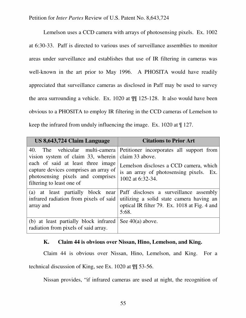
Petition for Inter Partes Review of U.S. Patent No. 8,643,724
55
Lemelson uses a CCD camera with arrays of photosensing pixels. Ex. 1002
at 6:30-33. Paff is directed to various uses of surveillance assemblies to monitor
areas under surveillance and establishes that use of IR filtering in cameras was
well-known in the art prior to May 1996. A PHOSITA would have readily
appreciated that surveillance cameras as disclosed in Paff may be used to survey
the area surrounding a vehicle. Ex. 1020 at ¶¶ 125-128. It also would have been
obvious to a PHOSITA to employ IR filtering in the CCD cameras of Lemelson to
keep the infrared from unduly influencing the image. Ex. 1020 at ¶ 127.
US 8,643,724 Claim Language Citations to Prior Art
40. The vehicular multi-camera vision system of claim 33, wherein each of said at least three image capture devices comprises an array of photosensing pixels and comprises filtering to least one of
Petitioner incorporates all support from claim 33 above.
Lemelson discloses a CCD camera, which is an array of photosensing pixels. Ex. 1002 at 6:32-34.
(a) at least partially block near infrared radiation from pixels of said array and
Paff discloses a surveillance assembly utilizing a solid state camera having an optical IR filter 79. Ex. 1018 at Fig. 4 and 5:68.
(b) at least partially block infrared radiation from pixels of said array.
See 40(a) above.
K. Claim 44 is obvious over Nissan, Hino, Lemelson, and King.
Claim 44 is obvious over Nissan, Hino, Lemelson, and King. For a
technical discussion of King, see Ex. 1020 at ¶¶ 53-56.
Nissan provides, “if infrared cameras are used at night, the recognition of
Petition for Inter Partes Review of U.S. Patent No. 8,643,724
56
obstructions becomes easier even if the illumination is inadequate.” Ex. 1004 at
7:9-11. Lemelson discusses a system and method employing a television scanning
camera mounted on a vehicle for scanning the field ahead, such as the image of the
road ahead of the vehicle. The Lemelson system also includes a computer for
analyzing the image signals generated. In this system, automatic image
intensifying means, or infra-red scanning and detection means, are utilized to
permit scanning operations to be effected during driving at night and in low light,
snowing or fog conditions. Ex. 1002 at 4:8-15. A PHOSITA would have readily
appreciated that the system of Lemelson was designed to provide the driver with
the maximum amount of useful information on a reconfigurable display under all
types of environmental conditions. Ex. 1020 at ¶¶ 129-134. Accordingly, it
would have been obvious to combine Nissan, Hino, Lemelson, and King to
provide the driver with a visible display device under high ambient light
conditions, i.e., when operating the vehicle during the daytime when more sunlight
is present, by implementing a circular polarizer in the reconfigurable display
device as disclosed by King. Id.
US 8,643,724 Claim
Language
Citations to Prior Art
44. The vehicular multi-camera vision system of claim 1, wherein said display device comprises
Lemelson discloses a reconfigurable display device. Ex. 1002 at 6:46-54; 15:45-54.
King discloses a circular polarizer: “If desired, a circularly polarized filter may be used with the
Petition for Inter Partes Review of U.S. Patent No. 8,643,724
57
a circular polarizer. structure of Fig. 1 to further reduce the reflected light and to achieve acceptable contrast in high ambient light conditions.” Ex. 1014 at 5:9-15; 35-42.
L. Claim 45 is obvious over Nissan, Hino, Lemelson, and Goesch
Claim 45 is obvious over Nissan, Hino, Lemelson, and Goesch. For a
technical discussion of Goesch, see Ex. 1020 at ¶¶ 73-77. Lemelson contemplates
a head up display (HUD) which projects a virtual image on the front windshield.
Goesch provides a HUD which projects a virtual image at the front bumper. Ex.
10212 at Fig. 1. Goesch states “the driver can keep his eyes looking toward the
road ahead while accessing and responding to the information” shown. Ex. 1022
at p. 55, 1:35-38. It would have been obvious to a PHOSITA to combine Goesch
with Nissan, Hino, and Lemelson because all of the references describe a driver
assist system that displays an image to the driver. Ex. 1020 at ¶¶ 135-138Further,
the explicit reference to a HUD and driver safety in Lemelson would have
motivated a PHOSITA to look to Goesch to provide an image which does not
require a driver to shift his/her focus from the road, which provides for a safer
display of information. Id.
US 8,643,724 Claim Language Citations to Prior Art
45. The vehicular multi-camera vision system of claim 1, wherein the image displayed by said display screen comprises a focal length that is substantially the depth of the field of the driver viewing objects beyond
Lemelson discloses a head up display. Ex. 1002 at 2:53-60.
Goesch discloses a head up display (HUD) which depicts a virtual image at/near the front bumper of the vehicle, at the depth of
Petition for Inter Partes Review of U.S. Patent No. 8,643,724
58
said equipped vehicle. the field of view of the driver. Ex. 1022 at Fig. 1 and p. 55, 1:35-38.
M. Claims 46 and 47 are obvious over Nissan, Hino, Lemelson, and
Lelong.
Claims 46 and 47 are obvious over Nissan, Hino, Lemelson, and Lelong.
For a technical discussion of Lelong, see Ex. 1019 at ¶¶ 90-93.
It would have been obvious for a PHOSITA to combine Nissan, Hino,
Lemelson, and Lelong because both Nissan and Hino provide the driver with a
seamless view from a single location. Ex. 1019 at ¶¶ 110-113. Further, all three
of Nissan, Hino, and Lemelson contemplate multiple cameras mounted to a
vehicle to provide the driver with camera views surrounding the vehicle, where the
camera images from each of the cameras are combined to be viewable by the
driver. Ex. 1020 at ¶¶ 82-88. Nissan explicitly mentions a rearward facing view
provided to the driver. Ex. 1002 at 1:25-33. In addition, Lemelson provides,
“[M]ultiple cameras may be used for front, side and rear viewing and for stereo
imaging capabilities suitable for generation of three-dimensional image
information, including capabilities for depth perception and placing multiple
objects in three dimensional image fields to further improve hazard detection
capabilities.” Ex. 1002 at 6:36-41. Meanwhile, Lelong explains, “[T]he invention
is also used in the field of automobile construction for realizing peripheral and
panoramic rear-view means without a blind angle.” Ex. 1013 at 1:13-18; 31-33. It
Petition for Inter Partes Review of U.S. Patent No. 8,643,724
59
would have been an obvious design choice to provide a rearward-facing view to
the driver in addition to the bird’s eye view disclosed by Nissan and Hino. Ex.
1019 at ¶¶ 149-153.
US 8,643,724 Claim Language Citations to Prior Art
46. The vehicular multi-camera vision system of claim 1, wherein said synthesized image displayed by said display screen approximates a panoramic view as would be viewed from a single virtual camera located exterior the equipped vehicle.
Nissan discloses a synthesized image by “an image portion from an image captured by each of multiple image capture devices 1 to N are combined into one image.” Ex. 1004 at 4:15-18.
Lelong discloses panoramic imaging from the position of a single virtual camera: “an image processing device comprising a system of n fixed real cameras arranged in such a way that their individual fields of view merge so as to form a single wide-angle field of view for observation of a panoramic scene.” Ex. 1013 at 1:13-18.
Lelong also discloses “[t]he invention is also used in the field of automobile construction for realizing peripheral and panoramic rear-view means without a blind angle.” Ex. 1013 at 1:31-33.
47. The vehicular multi-camera vision system of claim 1, wherein said synthesized image displayed by said display screen approximates a substantially seamless panoramic view as would be viewed from a single virtual camera located exterior the equipped vehicle.
Petitioner incorporates all support from claims 46 and 48, above.
The panoramic view in Lelong is seamless. Ex. 1013 at Fig. 7C and 7D.
VIII. CONCLUSION
For the foregoing reasons, inter partes review and cancellation of claims 1-
Petition for Inter Partes Review of U.S. Patent No. 8,643,724
60
48 of U.S. Patent No. 8,643,724 is respectfully requested.
Dated: November 7, 2014. Respectfully submitted,
/s/Tammy J. Terry Tammy J. Terry Reg No. 69, 167 [email protected] Seema Mehta Reg No. 56,235 [email protected] Peter C. Schechter (Reg. No. 31,662) [email protected] Aly Dossa (Reg. No.: 63,372) [email protected]
OSHA LIANG LLP
909 Fannin Street, Suite 3500 Houston, Texas 77010 Tel: 713-228-8600 Fax: 713-228-8778
Counsel for Petitioners Valeo North
America, Inc., Valeo S.A., Valeo
GmbH, Valeo Schalter und Sensoren
GmbH, and Connaught Electronics
Ltd.
Petition for Inter Partes Review of U.S. Patent No. 8,643,724
i
CERTIFICATE OF SERVICE
The undersigned certifies service pursuant to 37 C.F.R. §§ 42.6(e) and
42.105(a) of a copy of this Corrected Petition for Inter Partes Review on Magna
Electronics, Inc. via FedEx next day delivery to the correspondence address of
record for the ’724 patent as follows:
Magna Electronics, Inc. c/o Terence J. Linn Gardner Linn Burkhart & Flory 2851 Charlevoix Drive SE, Suite 207 Grand Rapids, MI 49546
Magna Electronics, Inc. 2050 Auburn Rd. Auburn Hills, MI 48326
Dated: November 7, 2014 Respectfully submitted,
/s/Tammy J. Terry Tammy J. Terry Reg No. 69, 167 [email protected] Seema Mehta Reg No. 56,235 [email protected] Peter C. Schechter (Reg. No. 31,662) [email protected] Aly Dossa (Reg. No.: 63,372) [email protected]
OSHA LIANG LLP
909 Fannin Street, Suite 3500 Houston, Texas 77010 Tel: 713-228-8600 Fax: 713-228-8778
Petition for Inter Partes Review of U.S. Patent No. 8,643,724
ii
Counsel for Petitioners Valeo North
America, Inc., Valeo S.A., Valeo
GmbH, Valeo Schalter und Sensoren
GmbH, and Connaught Electronics
Ltd.