In the name of God Computer Graphics Bastanfard. Last week Introduction Graphic system Standard...
24
In the name of God Computer Graphics Bastanfard
-
Upload
abel-summers -
Category
Documents
-
view
220 -
download
0
Transcript of In the name of God Computer Graphics Bastanfard. Last week Introduction Graphic system Standard...

In the name of God
Computer Graphics
Bastanfard

Last week
• Introduction
• Graphic system
• Standard Graphics
• Transformation

Graphics system overview
Hardware components
• Video monitors, hardcopy output devices, input
devices, components for interacting with virtual
environments
Software components
• CAD packages, paint programs, library of graphics routines to generate pictures

Graphic Software(1)Two types: special purpose and general programming
packages. The first type is for nonprogrammers to generate pictures/charts without worrying about details to produce displays. Easy to use menus are provided. Medical, business, CAD applications
• The general programming package has a library of graphics functions that can used in Languages such as C, C++, Java or Fortran. Basic components include those for specifying:
• picture components (straight lines, polygons, sphere, cube and other objects)
• setting color values
• selecting views of the scene
• applying transformations such as rotations

Graphic Software(2)• Examples of the general graphics programming
packages are: GL (graphics library), OpenGL, VRML (virtual-reality modeling language), Java 2D, Java 3D
• GKS, 3D GKS, PHIGS, and PHIGS+
• ISO and ANSI approved programming packages are: GKS, 3D GKS, PHIGS, and PHIGS+
• Others standards are GL and OpenGL
• Used in PL are: Open inventor, renderMan,.
• MatLab, Mathematics, and Maple provide a set of graphics programming functions

Computer Graphics API• OpenGL graphics output primitives are
functions used to describe picture components. Output primitives describing geometry of objects are geometric primitives (line, circle, polygon etc).
• Explore how primitives are implemented (and improved) via device level algorithm.
• Research in computer graphics improved techniques for special applications for faster, realistic, cheaper graphic displays.

Today
• Introduction
• Geometry
• Output
• Graphic Output Primitives
• Attribute of graphic primitives

a library of functions that we can use within a programming language such as C++ to create pictures
Introduction(1)
A general software package for graphics applications
sometimes
a computer-graphics application programming interface(CG API)
referred to as
Provide

Introduction(2)
Those functions in a graphics package describe the various picture components
are called the graphics output primitives, or simply primitives.
the first things for creating a picture is describing the
component parts of the scene to be displayed.
For each type of scene, wedescribe the structure of the individual Objects and their coordinate locations
within the scene.

Introduction(3)
The output primitives describing the geometry of objects as geometric primitives.
Like Point positions and straight-line segments as the simplest geometric primitives.

Introduction(4)
Additional geometric primitives that can be available in a graphics
package.
include circles and other conic sections, quadric surfaces, spline curves and surfaces,polygon color areas & functions for char.
After specifying the geometry of object within a selected coordinate reference frame, the output primitives are projected to a two dimensional
plane, corresponding to the display area of an output device, and scan converted into integer pixel positions within the frame buffer.

Coordinate reference frame(1)• To describe a picture, • we first decide upon a convenient Cartesian coordinate
system, called the world-coordinate reference frame, which could be either two dimensional or three-dimensional.
• We then describe the objects in our picture by giving their geometric specifications in terms of positions in world coordinates.
• For instance, we define a straight-line segment with two endpoint positions, and a polygon is specified with a set of positions for its vertices. These coordinate positions are stored in the scene description along with other information about the objects, such as their color and their coordinate extents, which are the minimum and maximum x , y , and z values for each object.

Coordinate reference frame(2)
• A set of coordinate extents is also described as a bounding box for an object.
• For a two dimensional figure, the coordinate extents are sometimes called an object’s bounding rectangle. Objects are then displayed by passing the scene information to the viewing routines, which identify visible surfaces and ultimately map the objects to positions on the video monitor. The scan-conversion process stores information about the scene, such as color values, at the appropriate locations in the frame buffer, and the objects in the scene are displayed on the output device.

Screen Coordinate(1)• Locations on a video monitor are referenced in integer screen
coordinates, which correspond to the pixel positions in the frame buffer.
• Pixel coordinate values give the scan line number (the y value) and the column number (the x value along a scan line).
• Hardware processes, such as screen refreshing, typically address pixel positions with respect to the top-left corner of the screen. Scan lines are then referenced from 0, at the top of the screen, to some integer value, y max , at the bottom of the screen, and pixel positions along each scan line are numbered from 0 to x max , left to right. However, with software commands, we can set up any convenient reference frame for screen positions.
• For example, we could specify an integer range for screen positions with the coordinate origin at the lower-left of a screen area (Fig. 3-1), or we could use non integer Cartesian values for a picture description.
• The coordinate values we use to describe the geometry of a scene are then converted by the viewing routines to integer pixel positions within the frame buffer.

Screen Coordinate(2)• For example, we could specify• an integer range for screen positions with the
coordinate origin at the lower-left of a screen area, or we could use non integer Cartesian values for a picture description.
• The coordinate values we use to describe the geometry of a scene are then converted by the viewing routines to integer pixel positions within the frame buffer.
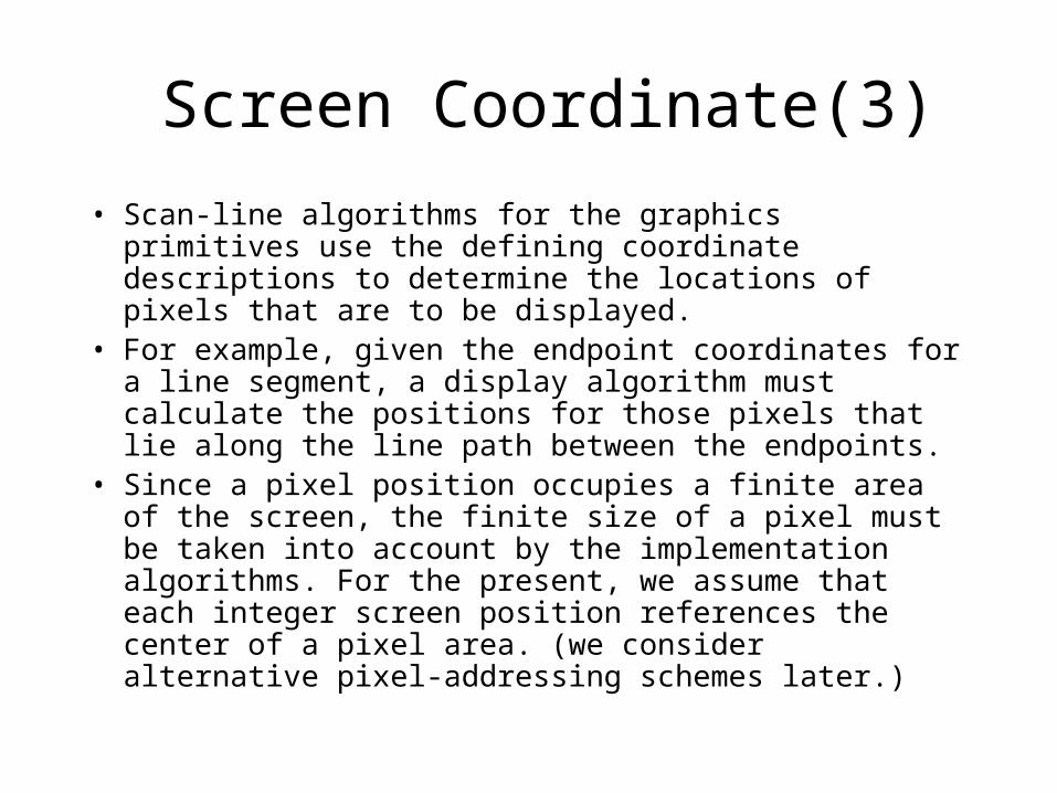
Screen Coordinate(3)
• Scan-line algorithms for the graphics primitives use the defining coordinate descriptions to determine the locations of pixels that are to be displayed.
• For example, given the endpoint coordinates for a line segment, a display algorithm must calculate the positions for those pixels that lie along the line path between the endpoints.
• Since a pixel position occupies a finite area of the screen, the finite size of a pixel must be taken into account by the implementation algorithms. For the present, we assume that each integer screen position references the center of a pixel area. (we consider alternative pixel-addressing schemes later.)

Point
• To specify the geometry of a point, • we simply give a coordinate position in the
world reference frame. • Then this coordinate position, along with other
geometric descriptions we may have in our scene, is passed to the viewing routines. Unless we specify other attribute values, OpenGL primitives are displayed with a default size and color.
• The default color for primitives is white and the default point size is equal to the size of one screen pixel.

Aim
Explore how primitives are implemented (and improved) via device level algorithm.
Why?
Research in computer graphics improved techniques for special applications for faster, realistic, cheaper graphic displays.

Line Drawing Algorithm
Graphics packages typically provide a function for specifying one or more straight-line segments, where each line segment is defined by two endpoint coordinate positions.

Line Drawing Algorithm• A straight-line segment in a scene is defined by
the coordinate positions for the endpoints of the segment.
• Example,• A computed line position of (10.48, 20.51), for
example, is converted to pixel position (10, 21). • This rounding of coordinate values to integers
causes all but horizontal and vertical lines to be displayed with a stair-step appearance (“the jaggies”)
• Improvement• high-resolution systems. • adjusting pixel intensities along the line path.

Display the line on a Raster Monitor
• This process digitizes the line into a set of discrete integer positions that, in general, only approximates the actual line path.
the graphics system must first project the endpoints to integer screen coordinates and determine the nearest pixel positions along the line path between the two endpoints.
Reading from the frame buffer, the video controller plots the screen pixels. This process digitizes the line into a set of discrete integer positions that,
in general, only approximates the actual line path
The line color is loaded into the frame buffer at the corresponding pixel coordinates.
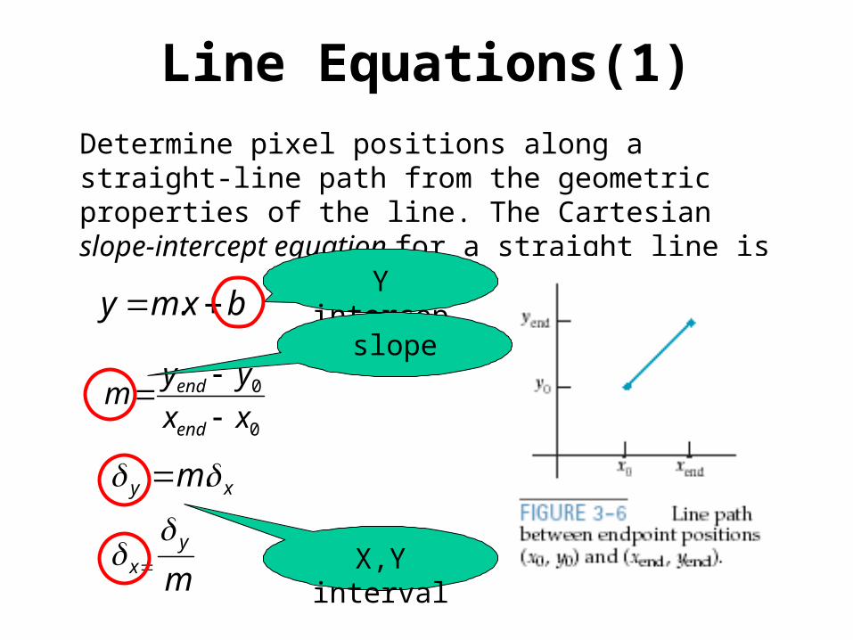
Line Equations(1)Determine pixel positions along a straight-line path from the geometric properties of the line. The Cartesian slope-intercept equation for a straight line is
bxmy .
0
0
xx
yym
end
end
m
m
yx
xy
.
Y intercept
X,Y interval
slope

Line Equation(2)
Voltage deflection in analog display like vector-scan system
m
m
yx
xy
.
X,Y interval

Voltage deflection in analog display like vector-scan system
For lines whose slopes have magnitudes | m | > 1, be set proportional to a small vertical deflection voltage with the corresponding horizontal deflection voltage set proportional to , calculated from Eq. 3-5. For lines with m = 1, = and the horizontal and vertical deflections voltages are equal. In each case, a smooth line with slope m is
generated between the specified end points.
m
m
yx
xy
.
X,Y interval
y
x x y