In situ Raman analysis of sol-gel synthesised antimony...
33
In situ Raman analysis of sol-gel synthesised antimony particles Nicholas E. Drewett a,b , Iain M. Aldous a , Jianli Zou a and Laurence J. Hardwick a,* a Univ. Liverpool, Dept. Chem., Liverpool L69 7ZD, Merseyside, England. b Present address: CIC Energigune, Parque Tecnológico de Álava, Albert Einstein, Álava * Corresponding author. Email address: [email protected] Keywords: in situ Raman analyses, intermetallic antimony anode, lithium ion battery, sodium ion battery, facile sol-gel synthesis
Transcript of In situ Raman analysis of sol-gel synthesised antimony...
In situ Raman analysis of sol-gel synthesised antimony particles
Nicholas E. Drewetta,b, Iain M. Aldousa, Jianli Zoua and Laurence J. Hardwicka,*
a Univ. Liverpool, Dept. Chem., Liverpool L69 7ZD, Merseyside, England.
b Present address: CIC Energigune, Parque Tecnológico de Álava, Albert Einstein, Álava
* Corresponding author. Email address: [email protected]
Keywords: in situ Raman analyses, intermetallic antimony anode, lithium ion battery, sodium
ion battery, facile sol-gel synthesis
Abstract: A one-pot sol-gel autocombustion synthesis for carbon coated antimony
microparticles has been developed for the first time. The initial capacities of this material were
647 mAhg-1Sb vs. Li and 527 mAhg-1Sb vs. Na, with a good rate capability (8C: 398 and 356
mAhg-1Sb vs. Li and Na respectively) and cyclability (cycle 120 capacity retention: 86% vs.
Li, 91% vs. Na). The sol-gel syntheised Sb was found to be superior to commercial Sb of
similar particle size (ca. 5 – 50 μm), which is attributed to the carbon coating. In situ Raman
analysis was used to investigate key differences between the sol-gel synthesised and
commercial antimony materials during the 1st cycle, and additionally demonstrated that upon
charge both materials do not return to a crystalline material but instead to an amorphous phase
represented by a broad feature centred at ca. 140 cm-1.
1. Introduction
The ability to manage and store energy is crucial to modern society, and a key family
of devices capable of this are alkali metal-ion batteries. Both lithium- and sodium-ion
batteries are seeing increasing interest in their potential use for a wide range of areas,
from transportation and portable electronic devices to both stationary and grid storage.
However, with this comes an increasing demand to improve a range of properties to
make them more suitable for those applications [1–6].
Intermetallic negative electrodes (anodes) have received some attention due to their
potential use as high gravimetric capacity materials. However, their high gravimetric
capacity is often accompanied by a large volume change during
intercalation/deintercalation, which can lead to pulverisation of the particles. This in
turn can result in loss of electrical contact within the anode and damage to the surface
of the intermetallic particles, leading to continuous solid-electrolyte interphase (SEI)
formation/breaking and irreversible capacity loss [7–10]. Nevertheless, due to their
attractive properties there is still considerable appeal in developing and improving these
types of materials, particularly for sodium-ion batteries [11,12].
The intermetallic anode material antimony (Sb) has a number of properties that make
it of potential interest. Capable of alloying with both sodium and lithium with a
theoretical gravimetric capacity of 660 mAhg-1Sb (based on the capacity of M3Sb), even
in its bulk form it is a reasonably attractive anode, with good reversibility at low to
moderate current density [12–15]. Moreover, the use of antimony anodes offers a way
to investigate and compare a wide range of lithium and sodium electrochemical systems.
However, one key challenge is improving the electrochemical properties of antimony
by increasing its rate capability and mitigating the stress and strain caused by volumetric
changes during cycling.
One approach is to prepare new and unique micro- and nano-structures [12].
Consequently there has been interest in using antimony both as a pure anode and as a
composite with other materials. Research has been carried out into the lithiation of bulk
microcrystalline powders and vacuum evaporated thin-film materials [13,15],
antimony/carbon nanotube composites [16] and high-energy milled or chemically
synthesised antimony nanocomposites [17–21]. Stable and reversible sodiation has been
demonstrated for bulk antimony and in thin films [13,15], with work also having been
carried out into sodiation of antimony/carbon fibres [22] and mechanically milled
antimony/carbon nanocomposites [23]. Recently, nano-sized antimony particles were
synthesised and, after additional processing, were able to demonstrate excellent rate
capability and cyclability during both sodiation and lithiation [14]. However, these also
exhibited poorer coulombic efficiencies than bulk antimony in the initial cycle, which
has attributed to the larger surface area of the nanomaterials leading to increased
decomposition of electrolyte during the formation of the SEI layer [11,14].
Given that the surface stability of the antimony particles can dramatically affect the
electrochemical behaviour of the resulting electrode, decorating the surface with carbon
could well mitigate the effects of volume expansion and improve the cyclability of the
material. One facile way to achieve this is to use a sol-gel synthetic route, as this method
can often leave small traces of carbon residue on metal particles. Furthermore, since the
chemistry of sol-gel syntheses has enabled the production of a wide range of materials
with diverse nano- and micro-structures, some of which were used in lithium- and
sodium-ion systems, a practical sol-gel route to produce antimony particles would be
advantageous [24–31]. Given this, and thus the likely subsequent importance of
electrochemistry occurring at surface, the use of in situ Raman spectroscopy presents an
opportunity to investigate and understand these processes in relation to both the carbon
decorated antimony surface and the near-surface of the antimony particle itself.
However, until now few sol-gel routes have been developed for pure antimony metal
particles. In part this is due to the difficulty of forming a stable sol with an antimony
salt precursor, as well as the problem of controlling the oxidation, and thus combustion,
of the carbon gel without oxidising the antimony metal particles. Nevertheless, by using
a citric acid sol-gel route it is possible to mitigate some of these problems – the citric
acid not only forms the gel, but may also be capable of chelating metal ions to form a
more stable sol as well as facilitating their reduction [31–33]. Moreover, citric acid sol-
gel syntheses have previously been used to make nanoparticles of other metals [34] and
metal oxides, implying that should a suitable route be developed it may then be possible
to control and optimise the size of the resulting particles by controlling and optimising
the synthetic conditions [35,36].
In this work we report, for the first time to our knowledge, a one-pot sol-gel synthesis
of pure antimony metal particles. Furthermore, we use electrochemical and in situ
Raman spectroscopy to analyse the properties of the synthesised material, and to
compare these to those of commercial antimony.
2. Experimental
2.1. Overview of sol-gel antimony synthesis
The citric acid sol-gel synthesis (Scheme 1) may be thought of as taking place over
two general steps, i. Gelation and ii. Combustion.
During i. Gelation, the antimony precursor (SbCl3) and the gelation agent (citric acid)
are dissolved in ethanol, allowing the citric acid to complex with antimony ions and
preventing reaction with water during the addition of small quantities of aqueous
oxidising agent (NH4NO3). Given that citric acid has previously been shown to be able
to act as a weak reducing agent [32], it seems likely some degree of antimony reduction
takes place during this stage. After heating overnight, the gel has expanded to form a
white, porous, solidified foam which is then ready for combustion.
During ii. Combustion, the material is heated under an inert gas (argon). This initiates
the thermal decomposition of the oxidising agent resulting in the release of, amongst
others, oxygen gas, which then reacts with the hydrocarbon gel. It has previously been
shown that thermal decomposition of nitrates in citric acid gels can result in the
evolution of many gasses [34]. These include H2, H2O, CH4, NO, CO2, NH3 and NO2.
Given that H2 and CH4 are reducing agents it seems reasonable to conclude that some
degree of antimony reduction occurs during this step. After following a suitable heating
regime (as described in 2.2.), the final product was obtained. Thus, by controlling the
synthetic conditions (e.g. ratio of citric acid to antimony chloride, amount of NH4NO3
oxidising agent, argon gas flow rate, etc.) it was possible to create the desired antimony
product.
2.2. Synthesis of sol-gel antimony microparticles
Antimony trichloride (0.007 moles, 1 g) and citric acid (0.0083 moles, 1.6 g) were
dissolved in ethanol (12 ml). Ammonium nitrate (0.025 moles, 2 g) was dissolved in
water (2 ml). The two solutions were mixed and heated at 90 °C for approximately 0.5
hr, forming a viscous yellow gel which was then poured into a ceramic boat and heated
at 95 °C for 12 hr. The resulting white porous material was then heated at 180 °C hr-1
under a constant argon flow (approximately 0.5 ml s-1) to 200 °C for 2 hr, before being
cooled and ground. It was then heated again under argon at 180 °C hr-1 to 640 °C for 8
hr before being cooled and ground to obtain the final product.
2.3. Coin cell fabrication and testing
Sodium and lithium electrolytes were prepared from 1 M sodium and lithium
perchlorate (respectively) in dried, distilled propylene carbonate (PC), with 10 wt. %
fluoroethylene carbonate (FEC) additive to improve cycling stability [13,14].
To evaluate the performance of the antimony particles, composite electrodes were
fabricated by casting an aqueous mixture (antimony active material : carbon black
(Super C Li, IMERYS) : sodium carboxymethylcellulose in a ratio of 64 : 21 : 15 % by
weight) onto a copper foil current collector. Coin cells were assembled from CR2025
coin cell parts, the prepared antimony electrodes, a glass fibre separator (Whatman)
impregnated with the sodium or lithium electrolyte and sodium (Na) or lithium (Li)
metal counter electrode. In all cases, cells were sealed in a glove box under air and
moisture free conditions (O2 ˂ 0.1 ppm; H2O ˂ 0.1 ppm). The electrochemical
measurements were performed at 30 °C using a Maccor Series 4000 battery cycler. All
batteries were cycled in the 20 mV to 1.5 V potential range and the obtained capacities
were normalised by the mass of antimony. Here the C-rate is defined for 1C as the
current applied (660 Ag-1) to allow full discharge or charge within 1 hour.
2.4. Other analyses
Powder X-ray diffraction patterns were collected on a PANalytical X'Pert PRO HTS
X-Ray Diffractometer operating in reflection mode with CoK1 radiation ( = 1.79Å).
Scanning electron microscopy images were collected on a JEOL 6610 scanning
electron microscope operating at an accelerating voltage of 20.0 keV.
Raman electrodes were prepared from an electrode mixture (antimony active material
: carbon black (Super C Li, IMERYS) : poly(vinylidene fluoride-hexafluoropropylene)
co-polymeric binder (Kynar-flex, Arkema) in a ratio of 40 : 22 : 38% by weight) and
dibutyl phthalate (Aldrich) dispersed in acetone and cast at a thickness of 40 µm onto
glass. Once dry, the free-standing film was removed from the glass plate, the dibutyl
phthalate plasticiser extracted using diethyl ether and 4 mm diameter electrodes were
punched from the cast. These electrodes were then dried under vacuum at 90 °C,
weighed and transferred into an argon filled glovebox (O2, H2O < 1 ppm) for Raman
cell assembly.
The electrode loadings were 3 mg cm-2, with a typical electrode mass of ~0.4 mg.
The electrodes were then used as active material within an in situ Raman cell (ECC-
Opto-Std, El-Cell) with 1 M LiClO4 or NaClO4 in PC with 10 wt.% FEC and vs. lithium
or sodium metal, configured as used in previous studies in which the cell assembly is
described [37–39].
All Raman spectra, both in situ and ex situ, were recorded with a Raman microscope
(Renishaw inVia) using a 633 nm wavelength laser focussed through a microscope
(Leica) via a 50x objective (Leica).
3. Results and discussion
3.1. Material characterisation
In Figure 1 A) the powder X-ray diffraction (PXRD) pattern of the sol-gel synthesised
antimony is compared to those of a commercial antimony (Fisher Scientific, antimony
powder ~200 mesh) and a ICSD (Inorganic Crystal Structure Database) standard (PDF
number: 01-073-7856). There is a good agreement between the three powder XRD
patterns, demonstrating that the bulk of the sol-gel antimony has no antimony oxide
impurity.
Figure 1 B) shows the scanning electron microscope (SEM) images of the sol-gel
synthesised and commercial antimony. From this it can be seen that both materials
consist of particles with a broadly similar size range (~5 – 50 µm). However, though
there are similarities between the two materials in terms of the morphology (i.e. large-
to-small particles) and broad particle size range, the commercial material appears to
have a more ‘corrugated’ surface in comparison to the sol-gel antimony (likely due to
the choice of synthetic route). The sol-gel material, by comparison, appears to consist
of particles with a smoother surface, likely partly due to the antimony salt being well
dispersed throughout the sol-gel and partly due to carbon coating. Nevertheless, the
similar size range and similar morphology enables comparison between the two
materials.
The Raman spectra of the two materials were taken, as shown in Figure 1 C). While
both materials showed the expected antimony Eg and A1g bands, only the sol-gel
synthesised antimony exhibited a signal attributable to the D and G modes of disordered
carbon. It should also be noted that it is possible to observe differences in the positions
of the sol-gel and commercial antimony A1g and Eg bands (sol-gel: 145 and 114 cm-1;
commercial: 143 and 109 cm-1, respectively). It is possible to attribute these shifts to
confinement and strain resulting from the carbon coating of the particles [40], while the
shift in Eg band may also be related to increased background florescence from surface
groups upon the carbon coating. The Raman spectra of the sol-gel antimony, taken from
multiple particles throughout the sample, showed only bands attributable to Sb and
carbon. The ratios of peak intensities were similar at all points, implying a relatively
high degree of homogeneity at the 1 µm scale (i.e. the limit of resolution determined by
the area of the Raman laser).
In order to determine the amount of carbon present in both the sol-gel and commercial
antimony materials, carbon, hydrogen and nitrogen were quantified using CHN analyses
(see supplementary information, Table A1). Comparison between sol-gel and
commercial Sb revealed a greater quantity of all three elements, but particularly carbon,
for the sol-gel synthesised material (23.3 vs. 0.5 wt. % C for the sol-gel and commercial
antimony materials respectively). This is perhaps unsurprising given that sol-gel
methods, particularly when undertaken under an inert gas, have previously been shown
to be able to decorate or coat synthesised materials in a carbon layer, often leading to
improved electrochemical performance [41–43].
3.2. Cyclability and rate capability
To investigate the electrochemistry of the sol-gel and commercial antimony
materials, coin cell electrodes were fabricated and cycled at either C/2 or varying C rates
to produce the plots shown in Figure 2. Plots of cell potential vs. capacity were then
extracted for both the sol-gel synthesised and the commercial antimony vs. Li and vs.
Na, as seen in in Figure 3.
From Figure 2 A) and C) it can be seen that vs. Na and Li the cyclability of the sol-
gel synthesised antimony (Cycle 120 capacity retention: 86% vs. Li, 91% vs. Na) is
superior to that of the commercial antimony (Cycle 120 capacity retention: 45% vs. Li,
16% vs. Na). Given that appropriate carbon coating can help mitigate the performance
loss resulting from the cycling-induced antimony volume changes [17,44], it seems
likely that the disordered carbon coating layer seen in the Raman spectrum is responsible
for the superior performance of sol-gel synthesised antimony. The improvement in
cyclability is even more noticeable vs. Na than vs. Li, and may be a result of the
differences in expected volume changes [15] (~293% vs. Na, ~135% vs. Li) causing
greater pulverisation of the commercial antimony due to the absence of surface
protection comparative to the carbon coated sol-gel antimony.
The initial capacity vs. Li for the sol-gel antimony (647 mAhg-1Sb) is close to the
theoretical capacity of antimony (ca. 660 mAhg-1), and is higher than that of the
commercial antimony (622 mAhg-1Sb), which is also likely due to the enhanced surface
stability produced through the sol-gel route. The capacities of the initial cycles vs. Na
are higher for the commercial antimony (582 mAhg-1Sb) than for the sol-gel synthesised
antimony (527 mAhg-1Sb). This has been previously observed in other studies into
carbon coated antimony [45–47], and may be a result of decreased diffusion of the larger
sodium-ions through the carbon decorated interface.
Due to the differences in cyclabilty, it is impossible to directly compare the rate
capabilities of the sol-gel synthesised and commercial antimony materials.
Nevertheless, by comparing the 8C (cycles 42 – 51) and C/2 data (cycles 52 – 50) from
Figure 2 B) and D), it can be seen that the sol-gel material exhibits good rate capability
vs. both Li (at 8C: 398 mAhg-1Sb, 70% retention) and Na (at 8C: 356 mAhg-1Sb, 72%
retention). This is in contrast to the commercial vs. Li (at 8C: 285 mAhg-1Sb, 61%
retention) but particularly vs. Na (at 8C: 48 mAhg-1Sb, 35% retention).
Examination of the load curves of the antimony materials (Figure 3) reveals some
differences. For both vs. Li and vs. Na the first cycle discharge of the sol-gel synthesised
antimony plateaus at a lower voltage (~0.7 V vs. Li+/Li, ~0.4 V vs. Na+/Na) than that of
the commercial antimony (~0.86 V vs. Li+/Li, ~0.55 V vs. Na+/Na) and those generally
reported in the literature. Nevertheless, from the first cycle charge the sol-gel
synthesised antimony does exhibit plateaus at the same voltages as those in the
commercial antimony, implying similar alloying mechanisms in both.
The lithiation of antimony is believed to proceed via one intermediary crystalline
phase (Li2Sb), giving rise to two plateaus which are generally indistinguishable and
occur below 0.9 V vs. Li+/Li [14,48,49]. Delithiation then proceeds directly from Li3Sb
to Sb, giving one plateau at ~1 V vs. Li+/Li. This is in keeping with the observed results
for the commercial antimony and the sol-gel synthesised antimony after the first
lithiation. From the irreversible capacity data on cycling vs. lithium (see supplementary
information, Table A2) it can be seen that although the first cycle irreversible capacity
of the sol-gel synthesised antimony is larger than that of the commercial antimony, on
subsequent cycles it is less. This would suggest that not all the capacity below 0.35 V
vs. Li+/Li is irreversible. Moreover, this lower irreversible capacity would support the
proposal that the sol-gel antimony is benefiting from some degree of enhanced surface
stability.
The sodiation mechanism is more complex, involving multiple crystalline and
amorphous phases. Furthermore, the 1st cycle sodiation mechanism differs from that of
subsequent cycles, giving rise to one observable plateau at ~0.5 V vs. Na+/Na on
discharge for the 1st cycle and two observable plateaus at ~0.75 V vs. Na+/Na and ~0.5
V vs. Na+/Na thereafter. Consequently, assignation of the exact electrochemical
processes occurring at any given point is challenging, though studies for thin film [50]
and bulk antimony [51] do exist which help to explain these mechanisms. After the first
sodiation of the sol-gel synthesised antimony, on desodiation a flat plateau at ~0.75 V
vs. Na+/Na and a sloping plateau at ~0.8 – 0.9 V vs. Na+/Na is observed. On subsequent
sodiations, plateaus are observed starting at ~0.7 V, ~0.55 V and ~0.47 V vs. Na+/Na.
These results are comparable to the commercial antimony, and are in keeping with the
literature. Examination of the irreversible capacity data on cycling vs. sodium (see
supplementary information, Table A3) shows less irreversible capacity for the sol-gel
synthesised antimony from cycles 1 to 10, which would be in keeping with what would
be expected for a material with enhanced surface stability. Although the sol-gel
antimony has slightly greater irreversible capacity than the commercial antimony for
cycles 60 and 120, that may be a facet of the former’s far greater charge and discharge
capacity.
Examination of the load curves shown in Figure 3 also reveals that the sol-gel
antimony exhibits greater capacity below 0.35 V than the commercial antimony. Given
the lower irreversible capacity of the sol-gel antimony, it is unlikely that this is SEI
formation. Furthermore, a similar phenomenon has been observed for other carbon-
coated antimony materials [45–47], which indicates it is again a result of the carbon
coating.
3.3. In situ Raman spectroscopy
To further explore the electrochemical processes undergone by the materials, in situ
Raman studies were carried out on the prepared Raman electrodes of both sol-gel
synthesised and commercial antimony vs. Li and vs. Na. Raman cells were assembled
as shown in Figure 4, which were then cycled at a slow rate of 66 mAg-1Sb (C/10). It
should be noted that, due to the requirements for a free standing electrode for in situ
Raman analysis, the electrode formulation not optimised for long term cycling. The
higher carbon fraction and PVDF based binder is less flexible for volume expansion,
leading to a greater overpotential which is due to higher internal resistance.
There is also noticeably greater SEI formation (2 to 1.5 V vs. Li+/Li, 1.2 to 0.75 V
vs. Na+/Na) which is attributed to the reaction of FEC with the greater electrode fraction
of carbon black (approximate ratios Sb : C, Raman cast 3 : 1, coin cell cast 2 : 1).
In situ Raman spectroscopy was carried out on the sol-gel synthesised antimony vs.
Li, as shown in Figure 5. It has previously been shown that the structure at OCP is
trigonal A7 [52]. The A7 lattice system is rhombohedral and contains six atoms in the
unit cell occupying 6c position, denoted as the Sb-I phase. This is seen spectroscopically
as the A1g and Eg bands (at 150 cm-1 and 112 cm-1 respectively), which correspond to
longitudinal and transverse motion within the structure respectively [52].
During lithiation there is no noticeable change in the Raman spectra until ~0.9 V vs.
Li+/Li, indicating that this phase is stable up till then. At this point there is an observable
decrease in the A1g and Eg bands as the long range features in the antimony are lost. This
continues until 0.02 V vs. Li+/Li, at which point there no A1g or Eg bands are visible.
Interestingly, the A1g band intensity decreases faster than the Eg band, implying
lithiation affects the longitudinal order more rapidly.
On delithiation to 1.5 V vs. Li+/Li the A1g band at 152 cm-1 re-emerges, suggesting
that some degree of long range ordering is returning to the antimony system on
delithiation.
The sol-gel synthesised antimony does show some differences in comparison to the
in situ Raman of the commercial antimony, shown in Figure A1. While the commercial
antimony does exhibit a noticeable decrease of the A1g band, there is little change during
the plateau. Afterwards the A1g band continues decreasing until ~0.2 V vs. Li+/Li,
whereupon a decrease in the Eg band is also observed. However, unlike the sol-gel
antimony, even when held at 0.02 V vs. Li+/Li it is still possible to observe the A1g and
Eg bands, indicating some degree of long range order is retained. On delithiation there
is little change to those A1g and Eg bands. This is due to some antimony particles
becoming electronically disconnected during Li+ insertion and extraction as volume
expansion occurs. The carbon coating can be attributed to maintaining improved
electronic contact during ion insertion.
When cycled vs. Na it is possible to observe changes in the Raman spectral series of
the sol-gel synthesised antimony, shown in Figure 6, corresponding to structural
changes within the material. During cell discharge no peak shift is observed, suggesting
this phase is stable until 0.59 V vs. Na+/Na, where the intensity of both peaks decreases
and diminishes. This is expected for an alloying mechanism between sodium and
antimony [51].
Upon sodiation below 0.59 V vs. Na+/Na, it is possible to observe diminishing long
range features for antimony. Here that is seen below 0.44 V vs. Na+/Na as the Eg band
disappears into the noise [51,52]. The weak presence of the A1g band shows that some
order remains within the structure [52]. This is most likely similar to the recently
proposed phase of undersodiated Na3Sb or a-Na3−xSb upon the initial sodiation of the
antimony structure [51].
This contrasts with the commercial antimony (see supplementary information, Figure
A2), where the complete fade of the A1g band suggests that complete sodiation has taken
place, forming the Na3Sb product. This could result from the carbon coating restricting
sodium access to the sol-gel synthesised antimony. It may be that the carbon coating is
hindering the diffusion of the larger sodium ions into the antimony particles, which
would also explain the reduction in capacity compared to commercial antimony. The
presence of a broad band at ~187 cm-1, seen in both the commercial and sol-gel
synthesised antimony samples below 0.35 V vs. Na+/Na, may be attributable to a weak
signal from a NaSb phase [53]. The appearance of a broad feature at ~165 cm-1, also
seen in both materials, is indicative of host guest structures formed with the inclusion
of sodium atoms. These type of structures have previously been characterised from
Raman data of antimony, under pressure, as incommensurate monoclinic and tetragonal
host guest phases [52].
Upon charge, both the sol-gel synthesised and commercial antimony structures do
not return to a crystalline material, but instead to amorphous phases, represented by a
broad feature in the Raman spectra centred at ca. 140 cm-1 (spectrum 14 in Figure 5, 6,
A1 and A2). The appearance of a third feature (Figure 6, spectrum 14, 2.0 V) at ~160
cm-1 suggests that a partial host guest structure has remained, with Na+ trapped within
the antimony host.
To investigate the effect of discharge/charge on the carbon present in the sol-gel
synthesised material, Raman spectra were taken both vs. Li and vs. Na as shown in
Figure A3 A) and B). From this it can be seen that, during lithiation, there is a noticeable
shift in the G band from higher to lower wavenumbers (from ca. 1593 to 1543 cm-1), as
well as a considerable decrease in the intensity of the D and G bands. This is in keeping
with previous observations regarding the lithiation of amorphous carbons [54]. Hence,
some degree of Li+ insertion is occurring not only in the sol-gel synthesised antimony,
but also in the accompanying carbon coating. During sodiation there also appears to be
a slight decrease in D and G band intensity, though not to the same extent as during
lithiation. Thus the carbon coating was found to not sodiate to the same degree as it
lithiates. Similar to the delithiation, the desodiation does not appear to be completely
reversible.
The difference in the degree of lithiation of the sol-gel synthesised antimony carbon,
comparative to sodiation, may also be a contributing factor to the observed differences
between the capacity of the sol-gel synthesised material when cycled vs. Li and vs. Na,
with the carbon contributing to some of the larger capacity when cycled vs. Li. Given
that we propose the carbon is also improving the cyclability of the sol-gel synthesised
antimony this may mean that a more optimised synthesis, designed to leave only the
minimum carbon necessary to improve performance, could result in a material with both
greater cyclability and gravimetric capacity vs. Na.
From the examination of the electrochemistry and in situ Raman spectra of sol-gel
synthesised and commercial antimony materials, some observations may be highlighted:
The sol-gel synthesised antimony exhibits cyclability superior to that of the
commercial material, likely due to the former’s carbon coating protecting against
surface damage and the creation of electronically disconnected and inactive particles,
resulting from volume changes on cycling.
On the 1st cycle, the load curves show that the sol-gel antimony plateaus at a lower
voltage than the commercial. This may be attributed to increased internal resistance
resulting from the carbon coating.
The in situ Raman spectra of the sol-gel synthesised antimony exhibit some
differences to those of the commercial antimony during lithiation and sodation. The A1g
and Eg bands of the sol-gel antimony completely disappear indicating the loss of long
range order. By contrast, in the commercial material these bands were still visible
highlighting formation of electronic disconnected regions within the composite
electrode. The in situ Raman spectra during sodiation are also of interest, showing that
the sol-gel synthesised antimony does not appear to fully sodiate. It is proposed that the
carbon coating restricts access for the larger sodium ions, reducing their ability to diffuse
into the antimony particles.
Additionally, examination of the in situ Raman spectra of the D and G bands
assigned to the carbon coating of the sol-gel synthesised antimony demonstrates
variation in the behaviour vs. Li and Na. It is likely that the carbon coating is able to
reversibly (de)lithiate to a slightly greater extent than it is able to (de)sodiate. Thus it
may be that the carbon coating is able to contribute to some degree to the capacity of
the material, and to do more so vs. Li than vs. Na.
These insights, provided by the in situ Raman data, would explain why the sol-gel
antimony exhibits a slightly better capacity than the commercial when cycled vs. Li, but
an initially worse capacity when cycled vs. Na.
Finally, it is worth noting that the cyclability and rate capability of the sol-gel material
is superior to that of the commercial material, and compares favourably to recent
literature reports [45–47], demonstrating the utility of this particular synthetic route.
4. Conclusions
In summary, a general sol-gel synthetic route to antimony particles has been
developed. Even without any attempts to further optimise size or morphology this has
resulted in the formation of particles of dimensions 5 – 50 µm.
The synthesised sol-gel antimony has exhibited good electrochemical performance
for a material with particles of this size (647 and 622 mAhg-1Sb vs. Li and Na
respectively), when compared to both the commercial material (582 and 527 mAhg-1Sb
vs. Li and Na respectively). It also demonstrated decent rate capability (at 8C: 398 and
356 mAhg-1Sb vs. Li and Na respectively; 70% and 72% retention at C/2) and cyclability
(Cycle 120 capacity retention: 86% vs. Li, 91% vs. Na).
While these initial results for sol-gel synthesised antimony are promising for battery
anodes, further work is necessary and should be carried out into investigating and
optimising parameters in order to improve the materials electrochemical properties (e.g.
through the use of capping agents, different antimony precursors, any form of ball
milling / sieving or using different synthetic parameters such as different antimony
precursors or gelation times). However, we have demonstrated that it should now be
possible to exploit the tailorable nature of sol-gel synthetic routes to produce a wider
particle size range of antimony materials than previously accessible. Thus we believe
this work represents an important first step towards the wider use of antimony in future
battery electrochemical studies.
Finally, the use of in situ Raman to explore the 1st cycle charge and discharge vs. Na
and Li has revealed key differences between the sol-gel and commercial antimony
materials, which were then examined with respect to electrochemical behaviour. This
has demonstrated the utility of in situ Raman as a complementary analytical technique
for investigating alloying anode materials.
5. Acknowledgements
We acknowledge the Engineering and Physical Sciences Research Council (EPSRC)
for the funding of this research under grant number EP/K016954, and the
Nanoinvestigation Centre at Liverpool (NiCaL) for access to SEM instrumentation.
6. References
[1] K. C. Divya, J. Østergaard, Battery energy storage technology for power systems—An
overview, Electr. Power Syst. Res. 79 (2009) 511.
[2] B. Scrosati, J. Garche, Lithium batteries: Status, prospects and future, J. Power
Sources. 195 (2010) 2419.
[3] P. G. Bruce, S. A. Freunberger, L. J. Hardwick, J.-M. Tarascon, Li-O2 and Li-S
batteries with high energy storage, Nat. Mater. 11 (2012) 19.
[4] L. Lu, X. Han, J. Li, J. Hua, M. Ouyang, A review on the key issues for lithium-ion
battery management in electric vehicles, J. Power Sources. 226 (2013) 272.
[5] J. B. Goodenough, K.-S. Park, The Li-Ion Rechargeable Battery: A Perspective, J. Am.
Chem. Soc. 135 (2013) 1167.
[6] K. Kubota, S. Komaba, Review—Practical Issues and Future Perspective for Na-Ion
Batteries, J. Electrochem. Soc. 162 (2015) A2538.
[7] M. Holzapfel, H. Buqa, L. J. Hardwick, M. Hahn, A. Würsig, W. Scheifele, P. Novák,
R. Kötz, C. Veit, F.-M. Petrat, Nano silicon for lithium-ion batteries, Electrochim.
Acta. 52 (2006) 973.
[8] M. Marcinek, L. J. Hardwick, T. J. Richardson, X. Song, R. Kostecki, Microwave
plasma chemical vapor deposition of nano-structured Sn/C composite thin-film anodes
for Li-ion batteries, J. Power Sources. 173 (2007) 965.
[9] C. M. Hayner, X. Zhao, H. H. Kung, Materials for Rechargeable Lithium-Ion
Batteries, Annu. Rev. Chem. Biomol. Eng. 3 (2012) 445.
[10] H. Tian, F. Xin, X. Wang, W. He, W. Han, High capacity group-IV elements (Si, Ge,
Sn) based anodes for lithium-ion batteries, J. Mater. 1 (2015) 153.
[11] Y. Kim, K.-H. Ha, S. M. Oh, K. T. Lee, High-Capacity Anode Materials for Sodium-
Ion Batteries, Chem. Eur. J. 20 (2014) 11980.
[12] H. Kang, Y. Liu, K. Cao, Y. Zhao, L. Jiao, Y. Wang, H. Yuan, Update on anode
materials for Na-ion batteries, J. Mater. Chem. A. 3 (2015) 17899.
[13] A. Darwiche, C. Marino, M. T. Sougrati, B. Fraisse, L. Stievano, L. Monconduit,
Better Cycling Performances of Bulk Sb in Na-Ion Batteries Compared to Li-Ion
Systems: An Unexpected Electrochemical Mechanism, J. Am. Chem. Soc. 134 (2012)
20805.
[14] M. He, K. Kravchyk, M. Walter, M. V Kovalenko, Monodisperse Antimony
Nanocrystals for High-Rate Li-ion and Na-ion Battery Anodes: Nano versus Bulk,
Nano Lett. 14 (2014) 1255.
[15] L. Baggetto, P. Ganesh, C.-N. Sun, R. A. Meisner, T. A. Zawodzinski, G. M. Veith,
Intrinsic thermodynamic and kinetic properties of Sb electrodes for Li-ion and Na-ion
batteries: experiment and theory, J. Mater. Chem. A. 1 (2013) 7985.
[16] W. X. Chen, J. Y. Lee, Z. Liu, The nanocomposites of carbon nanotube with Sb and
SnSb0.5 as Li-ion battery anodes, Carbon N. Y. 41 (2003) 959.
[17] C.-M. Park, S. Yoon, S.-I. Lee, J.-H. Kim, J.-H. Jung, H.-J. Sohn, High-Rate
Capability and Enhanced Cyclability of Antimony-Based Composites for Lithium
Rechargeable Batteries, J. Electrochem. Soc. 154 (2007) A917.
[18] Á. Caballero, J. Morales, L. Sánchez, A simple route to high performance nanometric
metallic materials for Li-ion batteries involving the use of cellulose: The case of Sb, J.
Power Sources. 175 (2008) 553.
[19] C.-M. Park, H.-J. Sohn, Novel Antimony/Aluminum/Carbon Nanocomposite for High-
Performance Rechargeable Lithium Batteries, Chem. Mater. 20 (2008) 3169.
[20] J. H. Sung, C.-M. Park, Amorphized Sb-based composite for high-performance Li-ion
battery anodes, J. Electroanal. Chem. 700 (2013) 12.
[21] Y. Cheng, Z. Yi, C. Wang, L. Wang, Y. Wu, L. Wang, Nanostructured
Carbon/Antimony Composites as Anode Materials for Lithium-Ion Batteries with
Long Life, Chem. Asian J. 11 (2016) 2173.
[22] Y. Zhu, X. Han, Y. Xu, Y. Liu, S. Zheng, K. Xu, L. Hu, C. Wang, Electrospun Sb/C
Fibers for a Stable and Fast Sodium-Ion Battery Anode, ACS Nano. 7 (2013) 6378.
[23] J. Qian, Y. Chen, L. Wu, Y. Cao, X. Ai, H. Yang, High capacity Na-storage and
superior cyclability of nanocomposite Sb/C anode for Na-ion batteries, Chem.
Commun. 48 (2012) 7070.
[24] H. Liu, Y. P. Wu, E. Rahm, R. Holze, H. Q. Wu, Cathode materials for lithium ion
batteries prepared by sol-gel methods, J. Solid State Electrochem. 8 (2004) 450.
[25] L. J. Fu, H. Liu, C. Li, Y. P. Wu, E. Rahm, R. Holze, H. Q. Wu, Electrode materials
for lithium secondary batteries prepared by sol–gel methods, Prog. Mater. Sci. 50
(2005) 881.
[26] K. Dokko, J. Sugaya, H. Nakano, T. Yasukawa, T. Matsue, K. Kanamura, Sol–gel
fabrication of lithium-ion microarray battery, Electrochem. Commun. 9 (2007) 857.
[27] D. Yuan, W. He, F. Pei, F. Wu, Y. Wu, J. Qian, Y. Cao, X. Ai, H. Yang, Synthesis and
electrochemical behaviors of layered Na0.67[Mn0.65Co0.2Ni0.15]O2 microflakes as a
stable cathode material for sodium-ion batteries, J. Mater. Chem. A. 1 (2013) 3895.
[28] M. Iftekhar, N. E. Drewett, a. R. Armstrong, D. Hesp, F. Braga, S. Ahmed, L. J.
Hardwick, Characterization of Aluminum Doped Lithium-Manganese Rich
Composites for Higher Rate Lithium-Ion Cathodes, J. Electrochem. Soc. 161 (2014)
A2109. http://jes.ecsdl.org/cgi/doi/10.1149/2.0441414jes.
[29] S. Doubaji, M. Valvo, I. Saadoune, M. Dahbi, K. Edström, Synthesis and
characterization of a new layered cathode material for sodium ion batteries, J. Power
Sources. 266 (2014) 275.
[30] G. J. Owens, R. K. Singh, F. Foroutan, M. Alqaysi, C.-M. Han, C. Mahapatra, H.-W.
Kim, J. C. Knowles, Sol–gel based materials for biomedical applications, Prog. Mater.
Sci. 77 (2016) 1.
[31] A. E. Danks, S. R. Hall, Z. Schnepp, The evolution of “sol-gel” chemistry as a
technique for materials synthesis, Mater. Horizons. 3 (2016) 91.
[32] X. C. Jiang, C. Y. Chen, W. M. Chen, A. B. Yu, Role of Citric Acid in the Formation
of Silver Nanoplates through a Synergistic Reduction Approach, Langmuir. 26 (2010)
4400.
[33] M. Tella, G. S. Pokrovski, Stability and structure of pentavalent antimony complexes
with aqueous organic ligands, Chem. Geol. 292–293 (2012) 57.
[34] Y. Jiang, S. Yang, Z. Hua, H. Huang, Sol-gel autocombustion synthesis of metals and
metal alloys, Angew. Chemie - Int. Ed. 48 (2009) 8529.
[35] W. Morales, M. Cason, O. Aina, N. R. de Tacconi, K. Rajeshwar, Combustion
Synthesis and Characterization of Nanocrystalline WO3, J. Am. Chem. Soc. 130
(2008) 6318.
[36] A. Varma, A. S. Mukasyan, K. T. Deshpande, P. Pranda, P. R. Erri, Combustion
Synthesis of Nanoscale Oxide Powders: Mechanism, Characterization and Properties,
MRS Proc. 800 (2003) 1.
[37] C. Sole, N. E. Drewett, L. J. Hardwick, In situ Raman study of lithium-ion
intercalation into microcrystalline graphite, Faraday Discuss. 172 (2014) 223.
[38] C. Sole, N. E. Drewett, F. Liu, A. M. Abdelkader, I. A. Kinloch, L. J. Hardwick, The
role of re-aggregation on the performance of electrochemically exfoliated many-layer
graphene for Li-ion batteries, J. Electroanal. Chem. 753 (2014).
[39] J. Zou, C. Sole, N. E. Drewett, M. Velický, L. J. Hardwick, In Situ Study of Li
Intercalation into Highly Crystalline Graphitic Flakes of Varying Thicknesses, J. Phys.
Chem. Lett. 7 (2016) 4291.
[40] C. Y. Xu, P. X. Zhang, L. Yan, Blue shift of Raman peak from coated TiO2
nanoparticles, J. Raman Spectrosc. 32 (2001) 862.
[41] M. Gaberscek, R. Dominko, M. Bele, M. Remskar, D. Hanzel, J. Jamnik, Porous,
carbon-decorated LiFePO4 prepared by sol–gel method based on citric acid, Solid
State Ionics. 176 (2005) 1801.
[42] C. Xia, C. Nian, Z. Huang, Y. Lin, D. Wang, C. Zhang, One-step synthesis of carbon-
coated Li4Ti4.95Nd0.05O12 by modified citric acid sol–gel method for lithium-ion
battery, J. Sol-Gel Sci. Technol. 75 (2015) 38.
[43] K. Wang, Z. Yin, P. Zhao, Synthesis of macroporous Li4SiO4 via a citric acid-based
sol–gel route coupled with carbon coating and its CO2 chemisorption properties,
Ceram. Int. 42 (2016) 2990.
[44] X. Liu, Y. Du, X. Xu, X. Zhou, Z. Dai, J. Bao, Enhancing the Anode Performance of
Antimony through Nitrogen-Doped Carbon and Carbon Nanotubes, J. Phys. Chem. C.
120 (2016) 3214.
[45] L. Hu, X. Zhu, Y. Du, Y. Li, X. Zhou, J. Bao, A Chemically Coupled
Antimony/Multilayer Graphene Hybrid as a High-Performance Anode for Sodium-Ion
Batteries, Chem. Mater. 27 (2015) 8138.
[46] D. Y. W. Yu, S. K. Batabyal, J. Gun, S. Sladkevich, A. A. Mikhaylov, A. G.
Medvedev, V. M. Novotortsev, O. Lev, P. V. Prikhodchenko, Antimony and antimony
oxide@graphene oxide obtained by the peroxide route as anodes for lithium-ion
batteries, Main Gr. Met. Chem. 38 (2015) 43.
[47] N. Zhang, Y. Liu, Y. Lu, X. Han, F. Cheng, J. Chen, Spherical nano-Sb@C composite
as a high-rate and ultra-stable anode material for sodium-ion batteries, Nano Res. 8
(2015) 3384.
[48] J. Wang, I. D. Raistrick, R. A. Huggins, Behavior of Some Binary Lithium Alloys as
Negative Electrodes in Organic Solvent‐ Based Electrolytes, J. Electrochem. Soc. .
133 (1986) 457. http://jes.ecsdl.org/content/133/3/457.abstract.
[49] K. C. Hewitt, L. Y. Beaulieu, J. R. Dahn, Electrochemistry of InSb as a Li Insertion
Host: Problems and Prospects, J. Electrochem. Soc. 148 (2001) A402.
[50] L. Baggetto, H.-Y. Hah, J.-C. Jumas, C. E. Johnson, J. A. Johnson, J. K. Keum, C. A.
Bridges, G. M. Veith, The reaction mechanism of SnSb and Sb thin film anodes for
Na-ion batteries studied by X-ray diffraction, 119Sn and 121Sb Mössbauer
spectroscopies, J. Power Sources. 267 (2014) 329.
[51] P. K. Allan, J. M. Griffin, A. Darwiche, O. J. Borkiewicz, K. M. Wiaderek, K. W.
Chapman, A. J. Morris, P. J. Chupas, L. Monconduit, C. P. Grey, Tracking Sodium-
Antimonide Phase Transformations in Sodium-Ion Anodes: Insights from Operando
Pair Distribution Function Analysis and Solid-State NMR Spectroscopy, J. Am. Chem.
Soc. 138 (2016) 2352.
[52] O. Degtyareva, V. V Struzhkin, R. J. Hemley, High-pressure Raman spectroscopy of
antimony: As-type, incommensurate host-guest, and bcc phases, Solid State Commun.
141 (2007) 164.
[53] M. B. Tzolov, M. N. Iliev, Raman scattering from monoalkali (Na-Sb and K-Sb),
bialkali (Na-K-Sb) and multialkali (Na-K-Sb-Cs) photocathodes, Thin Solid Films.
213 (1992) 99.
[54] L. J. Hardwick, P. W. Ruch, M. Hahn, W. Scheifele, R. Kötz, P. Novák, In situ Raman
spectroscopy of insertion electrodes for lithium-ion batteries and supercapacitors: First
cycle effects, J. Phys. Chem. Solids. 69 (2008) 1232.

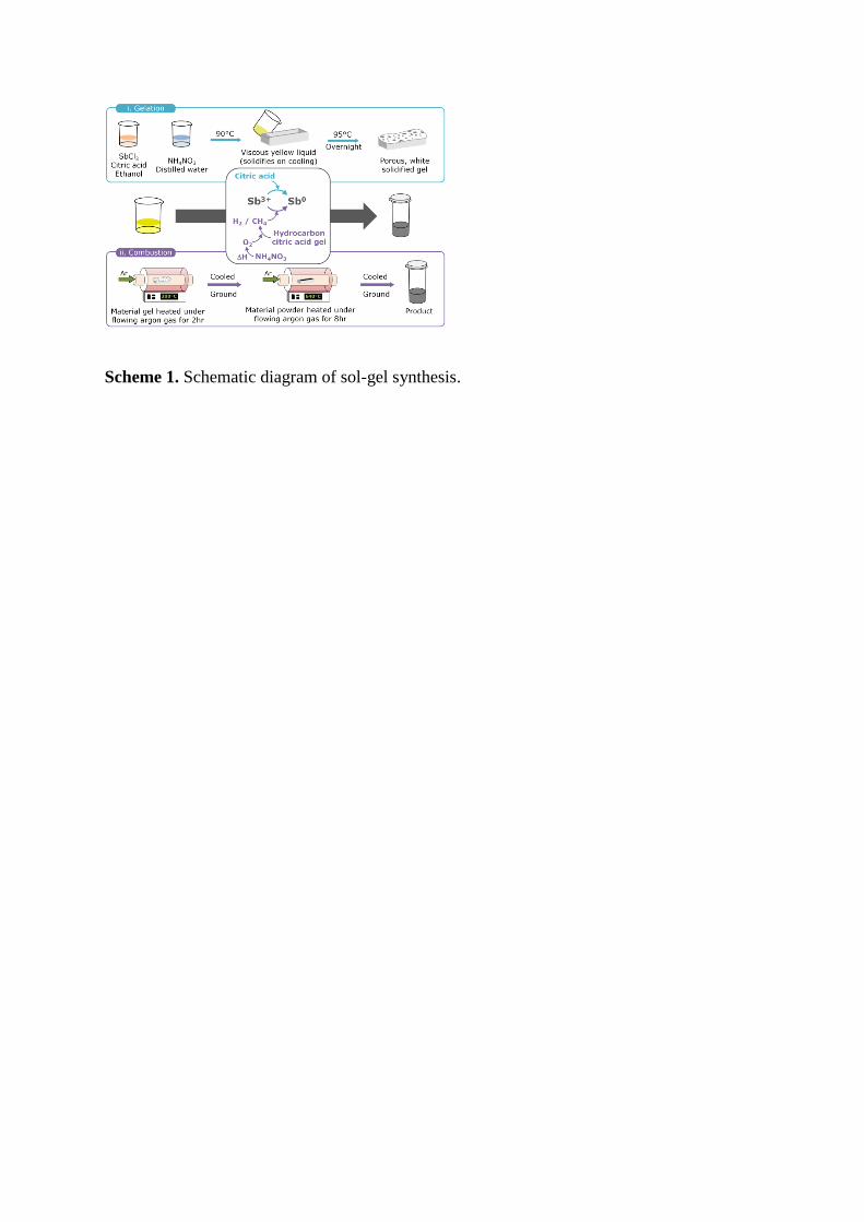
Scheme 1. Schematic diagram of sol-gel synthesis.

Figure 1. A) PXRD patterns for sol-gel synthesised, commercial and ICSD standard antimony.
B) Scanning electron microscope (SEM) images of the sol-gel synthesised and commercial
antimony. C) Raman spectra of the sol-gel synthesised and commercial antimony.
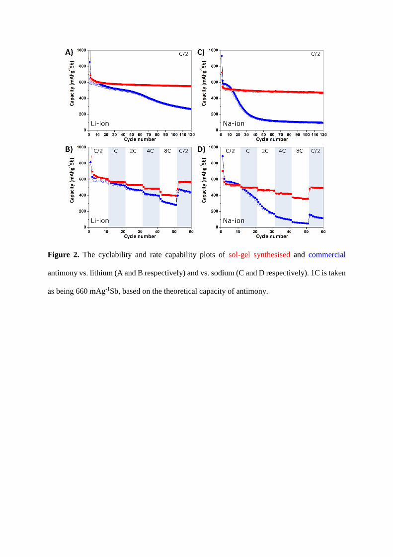
Figure 2. The cyclability and rate capability plots of sol-gel synthesised and commercial
antimony vs. lithium (A and B respectively) and vs. sodium (C and D respectively). 1C is taken
as being 660 mAg-1Sb, based on the theoretical capacity of antimony.
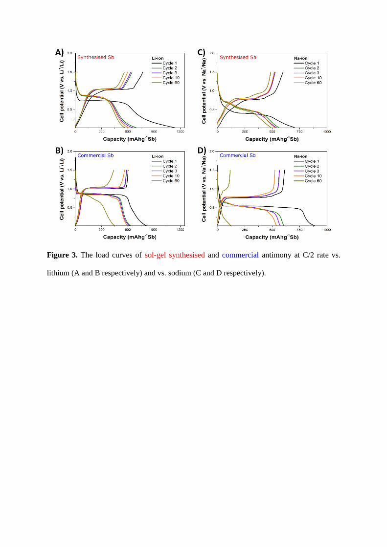
Figure 3. The load curves of sol-gel synthesised and commercial antimony at C/2 rate vs.
lithium (A and B respectively) and vs. sodium (C and D respectively).

Figure 4. Schematic of Raman cell setup.
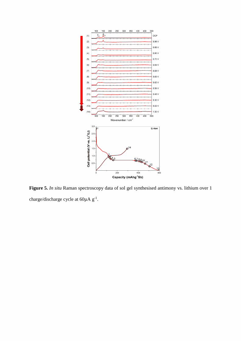
Figure 5. In situ Raman spectroscopy data of sol gel synthesised antimony vs. lithium over 1
charge/discharge cycle at 60µA g-1.
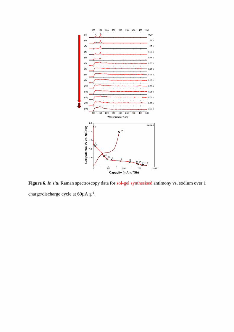
Figure 6. In situ Raman spectroscopy data for sol-gel synthesised antimony vs. sodium over 1
charge/discharge cycle at 60µA g-1.