IN-SITU CHEMICAL OXIDATION PRE-DESIGN · PDF fileQA/QC quality assurance/quality control QAPP...
22
IN-SITU CHEMICAL OXIDATION PRE-DESIGN INVESTIGATION WORK PLAN CTS OF ASHEVILLE, INC. SUPERFUND SITE 235 Mills Gap Road Asheville, Buncombe County, North Carolina EPA ID: NCD003149556 Consent Decree – Civil Action No. 1:16-cv-380 Prepared for: CTS Corporation 2375 Cabot Drive Lisle, Illinois 60532 Prepared by: Amec Foster Wheeler Environment & Infrastructure, Inc. 1308 Patton Avenue Asheville, North Carolina 28806 Amec Foster Wheeler Project 6252-16-2012 April 19, 2017 amec foster wheeler
Transcript of IN-SITU CHEMICAL OXIDATION PRE-DESIGN · PDF fileQA/QC quality assurance/quality control QAPP...

IN-SITU CHEMICAL OXIDATION PRE-DESIGN INVESTIGATION WORK PLAN
CTS OF ASHEVILLE, INC. SUPERFUND SITE 235 Mills Gap Road
Asheville, Buncombe County, North Carolina EPA ID: NCD003149556
Consent Decree – Civil Action No. 1:16-cv-380
Prepared for:
CTS Corporation 2375 Cabot Drive
Lisle, Illinois 60532
Prepared by:
Amec Foster Wheeler Environment & Infrastructure, Inc. 1308 Patton Avenue
Asheville, North Carolina 28806
Amec Foster Wheeler Project 6252-16-2012
April 19, 2017
amec foster wheeler

April 19, 2017
Mr. Craig Zeller, P.E. Superfund Remedial and Site Evaluation Branch U.S. Environmental Protection Agency 61 Forsyth Street, S.W. Atlanta, Georgia 30303-8960 [email protected]
Subject: ISCO Pre-Design Investigation Work Plan CTS of Asheville, Inc. Superfund Site
amec foster wheeler
235 Mills Gap Road, Asheville, Buncombe County, North Carolina Amee Foster Wheeler Project 6252-16-2012 EPA ID: NCO003149556 Consent Decree - Civil Action No. 1 :16-cv-380
Dear Mr. Zeller:
Please find attached the In-situ Chemical Oxidation (ISCO) Pre-Design Investigation Work Plan (POI Work Plan) for the above-referenced Site. Amee Foster Wheeler Environment & Infrastructure, Inc. prepared this POI Work Plan on behalf of CTS Corporation to comply with the Consent Decree for Interim Remedial Design/Remedial Action at the CTS of Asheville, Inc. Superfund Site between the United States of America and CTS Corporation, Mills Gap Road Associates, and Northrop Grumman Systems Corporation (entered on March 7, 2017).
If you have questions regarding this POI Work Plan, please contact us at (828) 252-8130.
Sincerely,
cc:
Correspondence: Amee Foster Wheeler Environment & lnfr~tructure, Inc. 1308 Patton Avenue Asheville, North Carolina 28806 Tel 828.252.8130 License Number: NC Corporate Engineering F-0653
Matthew E. Wallace, P.E. Principal Engineer

CTS of Asheville, Inc. Superfund Site ISCO Pre-Design Investigation Work Plan Amec Foster Wheeler Project 6252-16-2012 April 19, 2017
i
TABLE OF CONTENTS Page
List of Figures ....................................................................................................................... i List of Acronyms ................................................................................................................... ii Document Revision Log ....................................................................................................... ii
1.0 INTRODUCTION .......................................................................................................... 1
1.1 Site Description ..................................................................................................... 1 1.2 Background ........................................................................................................... 1 1.3 Pre-design Investigation Objectives ...................................................................... 2
2.0 NORTHERN AREA CONCEPTUAL SITE MODEL ..................................................... 3
2.1 Site Physical Setting ............................................................................................. 3 2.2 Geology ................................................................................................................. 3 2.3 Hydrogeology ........................................................................................................ 4 2.4 Nature and Extent of Contamination ..................................................................... 5
2.4.1 Unsaturated Soil ........................................................................................ 6 2.4.2 Groundwater .............................................................................................. 7
2.5 Fate and Transport ................................................................................................ 8 2.5.1 Contaminants of Concern .......................................................................... 9 2.5.2 Contaminant Transport Pathways ............................................................. 9 2.5.3 Mass Distribution ....................................................................................... 9
3.0 SCOPE OF WORK .................................................................................................... 10
3.1 Sampling and Analysis Plans .............................................................................. 10 3.2 Health and Safety ................................................................................................ 10 3.3 Membrane Interface Probe ................................................................................. 10 3.4 Soil Sampling ...................................................................................................... 11 3.5 Groundwater Sampling ....................................................................................... 12
4.0 SCHEDULE ............................................................................................................... 13
5.0 REFERENCES ........................................................................................................... 14
FIGURES
1 Topographic Site Location Map 2 Site Map 3 Previous and Proposed Boring Locations

CTS of Asheville, Inc. Superfund Site ISCO Pre-Design Investigation Work Plan Amec Foster Wheeler Project 6252-16-2012 April 19, 2017
ii
ACRONYMS
bgs below ground surface cis-1,2-DCE cis-1,2-dichloroethene CD Consent Decree DPT direct-push technology ECD electron capture device FSAP Field Sampling and Analysis Plan HASP Health and Safety Plan IROD Interim Record of Decision ISCO in-situ chemical oxidation MIP membrane interface probe NAPL non-aqueous phase liquid NOD natural oxidant demand PDI Pre-design Investigation PWR partially weathered rock QA/QC quality assurance/quality control QAPP Quality Assurance Project Plan RAO remedial action objective TCE trichloroethene (also, trichloroethylene) TCL Target Compound List USEPA United States Environmental Protection Agency VOC volatile organic compound
DOCUMENT REVISION LOG
Revision Date Description
0 4/19/2017 Initial Issuance
CTS of Asheville, Inc. Superfund Site ISCO Pre-Design Investigation Work Plan Amec Foster Wheeler Project 6252-16-2012 April 19, 2017
1
1.0 INTRODUCTION
Pursuant to Paragraph 3.3(a) of the Statement of Work, this document presents the In-situ
Chemical Oxidation (ISCO) Pre-design Investigation Work Plan (PDI Work Plan) for the
CTS of Asheville, Inc. Superfund Site (Site) located at 235 Mills Gap Road in Asheville,
Buncombe County, North Carolina (Figure 1). The activities described in this PDI Work
Plan will be performed to comply with the Consent Decree (CD) for Interim Remedial
Design/Remedial Action (Interim RD/RA) at the Site between the United States of America
and CTS Corporation, Mills Gap Road Associates, and Northrup Grumman Systems
Corporation. The CD was entered on March 7, 2017.
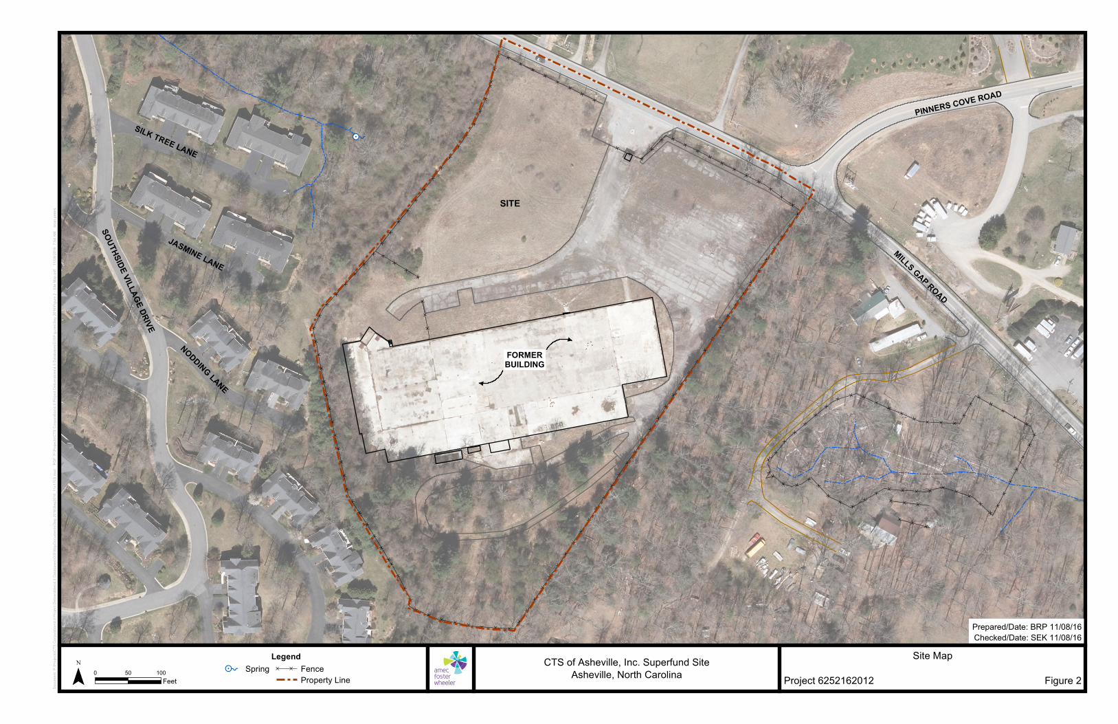
1.1 SITE DESCRIPTION
The approximate center of the Site is located at north latitude 35°29’36” and west
longitude 82°30’25”. The Site formerly contained an approximate 95,000-square foot,
single-story brick and metal structure on the southern portion of the Site. The building was
demolished in December 2011 and the concrete building pad remains intact. The
northeastern portion of the Site contains an asphalt-paved parking area, and asphalt-
paved driveways are located parallel to the north (front) of the building pad and southeast
(rear) of the building pad. A six-foot high chain-link fence surrounds the Site and a locked
gate at the north end of the Site controls access to the Site from Mills Gap Road. The Site
is unoccupied. The Site and adjacent property boundaries are illustrated on Figure 2.
1.2 BACKGROUND
Previous investigations have identified a dissolved-phase volatile organic compound
(VOC) groundwater plume in the Northern Area of the Site, with trichloroethene (TCE)
being the primary contaminant. ISCO using emplaced potassium permanganate will be
implemented in the Northern Area to reduce TCE concentrations in groundwater. The
remedial action objective is to reduce TCE concentrations in Northern Area groundwater
by 95 percent.
Additional information is required to design the proposed remedial alternative. This PDI
Work Plan describes data gaps to be addressed and investigation methods intended to fill
the identified data gaps.

CTS of Asheville, Inc. Superfund Site ISCO Pre-Design Investigation Work Plan Amec Foster Wheeler Project 6252-16-2012 April 19, 2017
2
1.3 PRE-DESIGN INVESTIGATION OBJECTIVES
The objective of the PDI is to collect additional information in the Northern Area of the Site
where ISCO will be implemented. The area proposed for remediation is approximately 1.9
acres (the Northern Area). One objective of the PDI is to gather data to better understand
the distribution of VOC contamination in the Northern Area groundwater plume so that
treatment can be focused in the areas of the highest contamination, both horizontally and
vertically. Another objective is to collect additional soil and groundwater data to provide
information for the design of the ISCO Treatability Study and the full-scale Remedial
Design.

CTS of Asheville, Inc. Superfund Site ISCO Pre-Design Investigation Work Plan Amec Foster Wheeler Project 6252-16-2012 April 19, 2017
3
2.0 NORTHERN AREA CONCEPTUAL SITE MODEL
The following Conceptual Site Model is based on data collected to date related to the
overburden formation in the Northern Area of the Site.
2.1 SITE PHYSICAL SETTING
The area surrounding the Site is considered rural and contains residential and light
commercial properties. The Site is situated on a topographic “saddle” between two
prominent mountains - Busbee Mountain to the north and Brown Mountain to the south
and southwest. Properties northwest and southeast are topographically downgradient of
the Site. The majority of the Site is relatively flat and natural surface drainage at the Site is
to the northwest. The surrounding area contains mountains and rolling hills, typical of the
eastern flank of the Appalachian Mountain range.
2.2 GEOLOGY
Fill material and residual soil (overburden) have been identified in the Northern Area of the
Site. Fill material, consisting of loose silty sand with gravel, has been observed to a depth
of approximately 20 feet below ground surface (bgs) (monitoring well MW-5 and soil
boring SB-01) in the northwestern portion of the Site where two apparent natural
intermittent surface water drainage channels were historically backfilled for
development/grading. Overburden is located below the fill material, where present, and
has been observed to a depth of approximately 81 feet bgs (monitoring well MW-6A) in
the Northern Area of the Site, where the apparent top of bedrock is encountered. The
uppermost zone of overburden generally consists of fine to medium sand with 10 to 15
percent silt. The overburden “fabric” ranges from massive (i.e., no apparent structure) to
strongly foliated. Foliated zones were observed to be approximately horizontal to steeply
dipping. Quartz veins ranging in thickness from less than 0.5 inches to approximately 12
inches, and consisting of sand to gravel-sized fragments, have been observed in the
overburden. The partially weathered rock (PWR), which is a zone of less weathered rock
than the shallower overburden, has been observed to be approximately 15 feet thick in the
Northern Area and typically samples as fine to coarse sand with minor amounts of silt and
gravel-sized rock fragments. The fabric of the PWR is similar to the overburden fabric
(MACTEC, 2009).
CTS of Asheville, Inc. Superfund Site ISCO Pre-Design Investigation Work Plan Amec Foster Wheeler Project 6252-16-2012 April 19, 2017
4
The depth to bedrock in the Northern Area ranges from approximately 50 feet bgs to
approximately 81 feet bgs, based on the depth to drilling refusal using rotary/roller cone
drilling equipment (MACTEC, 2009) and direct-sensing equipment (Amec, 2014).
2.3 HYDROGEOLOGY
A groundwater divide is present in the overburden in the north-central portion of the Site.
As previously discussed, the Site is located on a topographic saddle between mountains
to the north and south. A portion of groundwater that is flowing from each mountain (i.e.,
from a higher elevation) is presumed to be toward the saddle. Therefore, a groundwater
divide has developed where groundwater in the overburden flows from the mountains and
turns east or west to respective discharge zones. The position and shape of the
groundwater divide likely changes in response to precipitation/infiltration.
The direction of shallow groundwater flow (water table) and groundwater flow in the PWR
zone are similar. Groundwater flow in the southern portion of the Site appears to flow
radially, to the north and east. From the north/central portion of the Site, groundwater
flows northwest and east/southeast toward the respective groundwater discharge zones.
In January 2015, the depth to groundwater in the Northern Area of the Site ranged from
approximately 17 to 33 feet bgs in monitoring wells MW-7 and MW-6, respectively.
Considering the depth to the water table and the depth to bedrock, the aquifer thickness
ranges from approximately 30 to 60 feet. The horizontal hydraulic gradient in the shallow
overburden in the central portion of the Site is approximately 0.031. The horizontal
hydraulic gradient in the shallow overburden in the Northern Area of the Site toward the
discharge zone east of the Site is approximately 0.066 and the horizontal gradient from
Northern Area of the Site toward the discharge zone west of the Site is approximately
0.015 (Amec Foster Wheeler, 2015a).
The horizontal hydraulic gradient in the PWR in the source area at the Site is
approximately 0.018. The horizontal hydraulic gradient in the PWR from the Northern Area
of the Site toward the discharge zone east of the Site is approximately 0.063 and the
horizontal gradient from the Site toward the spring west of the Site is approximately 0.014
(Amec Foster Wheeler, 2015a).

CTS of Asheville, Inc. Superfund Site ISCO Pre-Design Investigation Work Plan Amec Foster Wheeler Project 6252-16-2012 April 19, 2017
5
Upward and downward vertical hydraulic gradients were measured between proximal
overburden shallow and PWR monitoring wells, based on the January 2015 monitoring
event. An upward gradient (-0.12) was measured at the MW-6/6A well pair and a relatively
small downward vertical gradient (0.0009) was measured at the MW-7/7A well pair. The
presence of essentially such a slight vertical gradient at the MW-7/7A well pair is
indicative of a groundwater divide at, or in the vicinity of, the well pair.
Groundwater elevations have fluctuated since monitoring wells were installed in 2009.
From 2009 to 2013, groundwater elevations in the Northern Area of the Site increased
10.8 feet and 12.5 feet at monitoring wells MW-7A and MW-6A, respectively. Groundwater
elevation increases in the shallow (water table) monitoring wells were similar during this
period (i.e., 11.1 feet at MW-7 and 11.2 feet at MW-6). From 2013 to 2015, groundwater
elevations decreased approximately 3 to 5 feet in the Northern Area of the Site.
The groundwater seepage velocity (v) is calculated as:
v = ki/ne, where k = hydraulic conductivity i= hydraulic gradient ne = effective porosity
Based on the average hydraulic conductivity of 2.3 x 10⁻⁴ cm/sec determined by slug
testing conducted for the non-aqueous phase liquid (NAPL) Area FFS Report (Amec
Foster Wheeler, 2015) and an assumed effective porosity of 0.25, the groundwater
seepage velocity from the Northern Area (monitoring well pairs MW-6/6A and 7/7A)
ranges from 13 feet per year to the western discharge zone, to 63 feet per year to the
eastern discharge zone.
2.4 NATURE AND EXTENT OF CONTAMINATION
As determined from previous investigations, and confirmed during the 2013/2014 NAPL
Investigation, the contamination source area is located below the south-central portion of
the former building and extends to the immediate south. The nature of the chlorinated
VOC contamination, whether from pure product or from a mixed material/liquid containing
a portion of chlorinated VOCs, is unknown. The primary release mechanism(s) associated
with the chlorinated VOC contamination observed at the Site is also unknown.

CTS of Asheville, Inc. Superfund Site ISCO Pre-Design Investigation Work Plan Amec Foster Wheeler Project 6252-16-2012 April 19, 2017
6
The petroleum contamination identified in the source area at the Site consists primarily of
fuel oil. The primary release mechanism(s) associated with the petroleum contamination
observed at the Site is unknown; however, the petroleum is suspected of originating from
an aboveground fuel oil storage tank formerly used to store and supply fuel oil to the
facility’s boiler.
Based on results from the NAPL Investigation, a significant portion of TCE has partitioned
into (i.e., dissolved into) the petroleum NAPL. Based on geochemical parameters,
primarily the octanol-water coefficient, TCE will more readily partition into the petroleum
NAPL than dissolve into groundwater; however, via equilibrium conditions, the TCE will
dissolve into groundwater over time (Amec, 2014). Therefore, the petroleum NAPL acts as
the primary source to the dissolved-phase groundwater plume, which extends north from
the north lobe of the NAPL zone, and east from the east lobe of the NAPL zone. From the
Northern Area of the Site, the dissolved-phase groundwater plume extends east and west
to discharge zones. There is no evidence of NAPL (either light or dense) in the
overburden in the Northern Area of the Site (Amec, 2014).
2.4.1 Unsaturated Soil
Unsaturated soil samples collected to date from the overburden in the Northern Area of
the Site do not indicate a source of soil contamination that contributes to the contaminated
groundwater plume in the Northern Area of the Site. For instance, four unsaturated soil
samples collected by USEPA subcontractors in late 2007/early 2008 did not indicate the
presence of Site-related VOCs in the Northern Area of the Site (TNA, 2008). Also, an
unsaturated soil sample collected from the MW-6 soil boring in September 2008 did not
indicate Site-related VOCs (MACTEC, 2009).
In 2010, the facility’s sanitary sewer line was located and unsaturated soil samples were
collected within approximately two feet below the identified sewer line, which extends from
the eastern portion of the former building to Mills Gap Road. Five unsaturated soil
samples (SS-126 through SS-130) were collected below the sewer line in the Northern
Area of the Site and minor concentrations of TCE were reported in two of the samples
(e.g., 5.4 and 8.1 micrograms per kilogram in SS-127 and SS-128, respectively;
MACTEC, 2010).

CTS of Asheville, Inc. Superfund Site ISCO Pre-Design Investigation Work Plan Amec Foster Wheeler Project 6252-16-2012 April 19, 2017
7
During the 2013/2014 NAPL Investigation, an electron capture device (ECD) was used to
qualitatively measure the concentration/amount of chlorinated VOCs, such as TCE,
adjacent to the ECD probe as it was advanced down through the overburden. The ECD
probe was advanced at 14 locations in the Northern Area of the Site. Elevated ECD
responses indicating the presence of chlorinated VOCs were not measured in the
unsaturated soil, and in many cases, the estimated depth of the water table was
consistent with the beginning of positive ECD responses indicating the presence of the
dissolved-phase chlorinated VOC plume in groundwater (Amec, 2014).
2.4.2 Groundwater
The dissolved-phase chlorinated VOC plume in overburden, primarily consisting of TCE,
extends from the source NAPL Area to the Northern Area and then east and west toward
groundwater discharge zones. Based on data collected during the NAPL Investigation
(Amec, 2014) and the Western Area Remedial Investigation (Amec Foster Wheeler,
2015b), the Northern Area dissolved-phase groundwater plume likely does not extend
north of Mills Gap Road. The core of the Northern Area groundwater plume (i.e., TCE
groundwater concentrations greater than 5,000 micrograms per liter, µg/L, and elevated
ECD responses observed during the NAPL Investigation) is depicted in Figure 3 and is the
focus of this PDI.
TCE is the primary chlorinated VOC present in groundwater in the Northern Area of the
Site. Minor concentrations of chlorinated VOC degradation products, such as 1,2-cis-
dichloroethene (cis-1,2-DCE), have been detected in groundwater samples collected from
the Northern Area. The lack of elevated concentrations of degradation products indicates
that natural biodegradation does not appear to be readily occurring in the Northern Area.
Based on the January 2015 sampling event, the pH of shallow groundwater in the
Northern Area of the Site (MW-6 and MW-7) was approximately 5, which could be one of
the factors limiting the ability of microbes to anaerobically biodegrade TCE to cis-1,2-DCE
(Amec Foster Wheeler, 2015). The pH of the deeper groundwater in the Northern Area of
the Site is approximately 7 and 9 in monitoring wells MW-6A and MW-7A, respectively. It
should be noted that the initial pH in groundwater purged from the deeper monitoring wells
after installation in 2009 ranged from 11 to 12, indicating likely grout/concrete
“contamination” from the alkaline grout/cement emplaced in the annulus of the monitoring
CTS of Asheville, Inc. Superfund Site ISCO Pre-Design Investigation Work Plan Amec Foster Wheeler Project 6252-16-2012 April 19, 2017
8
wells (Nielsen, 2006). The “elevated” pH readings in the January 2015 measurements in
the PWR wells could be a result of the continuing effect of the alkaline grout/cement used
in the well construction.
Concentrations of TCE vary horizontally and vertically in the Northern Area. Based on
TCE concentrations in collected groundwater samples and ECD responses, chlorinated
VOC concentrations generally increase with depth (Note: the ECD probe did not advance
to the depth of bedrock due to limitations of the drilling equipment; the ECD probe
generally advanced to a depth of approximately 50 feet bgs). The relatively significant
upward vertical hydraulic gradient (i.e., -0.015 in 2009 and -0.12 in 2015) at the MW-6/6A
monitoring well pair is likely the reason TCE concentrations in shallow groundwater at
MW-6 are higher as compared to TCE concentrations in shallow groundwater at MW-7,
where the vertical hydraulic gradient is very low (i.e., 0.004 upward in 2009 and 0.0009
downward in 2015).
Petroleum constituents have not been detected at elevated concentrations in groundwater
samples collected in the Northern Area of the Site. Relatively minor concentrations of
petroleum constituents (i.e., compared to reported TCE concentrations) were detected in
groundwater samples collected in January 2015 from monitoring well MW-6, as well as in
groundwater samples collected from SB-05 and SB-10 during the NAPL Investigation.
These minor concentrations indicate that the groundwater plume in the Northern Area of
the Site does contain a relatively small proportion of petroleum constituents. In general,
the petroleum constituents that have been detected are short-chain hydrocarbons (e.g.,
benzene, toluene, and xylenes) which more readily dissolve into groundwater from a
petroleum fuel source, such as the petroleum NAPL in the source area. Petroleum
constituents in groundwater in the Northern Area are not considered to contribute
significant mass to the overall contaminated groundwater plume.
2.5 FATE AND TRANSPORT
The fate and transport of contaminants in soil and groundwater is influenced by numerous
factors, including the primary and secondary release mechanisms; the physical and
chemical properties of the constituents that were released; and the characteristics of the
subsurface medium through which the contaminants migrate.
CTS of Asheville, Inc. Superfund Site ISCO Pre-Design Investigation Work Plan Amec Foster Wheeler Project 6252-16-2012 April 19, 2017
9
2.5.1 Contaminants of Concern
The primary constituent of concern for the Northern Area is TCE.
2.5.2 Contaminant Transport Pathways
The primary transport pathway for contamination in the overburden in the Northern Area is
via groundwater. The unsaturated soil pathway, where contaminants leach from the soil to
the underlying groundwater, is not considered a transport pathway, as evidence of
contamination in the unsaturated soil has not been identified in the Northern Area. The
dissolved-phase groundwater plume in the Northern Area discharges at surface water
features east and west of the Site resulting in an airborne contaminant pathway via
volatilization of VOCs, as well as a surface water contaminant transport pathway.
2.5.3 Mass Distribution
The NAPL source area at the Site contains the largest mass of contaminants. The
downgradient dissolved-phase plume contains chlorinated VOC degradation compounds
and minor concentrations of petroleum constituents. Groundwater in the Northern Area
contains concentrations of TCE ranging from hundreds µg/L to tens of thousands µg/L. As
previously described, concentrations of TCE vary horizontally and vertically in
groundwater in the Northern Area.
CTS of Asheville, Inc. Superfund Site ISCO Pre-Design Investigation Work Plan Amec Foster Wheeler Project 6252-16-2012 April 19, 2017
10
3.0 SCOPE OF WORK
The PDI will be conducted using qualitative and quantitative field techniques collected via
real-time direct-sensing equipment, as well as traditional laboratory methods.
3.1 SAMPLING AND ANALYSIS PLANS
The Remedial Design Work Plan contains a Field Sampling and Analysis Plan (FSAP)
and a Quality Assurance Project Plan (QAPP) that are associated with this PDI scope of
work.
The FSAP describes the data gathering methods, sampling equipment and procedures,
borehole abandonment procedures, decontamination procedures, and procedures for
management of investigative derived waste.
The QAPP describes the project objectives and organization, functional activities, and the
quality assurance and quality control protocols that will be used to achieve the desired
data quality objective for the project.
3.2 HEALTH AND SAFETY
A Site Health and Safety Plan (HASP) has been developed specific to the Site activities
and has been submitted to the USEPA under separate cover. The HASP applies to Amec
Foster Wheeler employees and Amec Foster Wheeler subcontractors, only. Field teams
will have a copy of the HASP during field activities. Personnel working at the Site during
the PDI will be required to read, understand, and conform to the requirements of the
HASP.
3.3 MEMBRANE INTERFACE PROBE
The membrane interface probe (MIP) allows for the real-time qualitative analysis of VOCs
in the subsurface. The MIP tool consists of a semi-permeable membrane mounted on the
outside of a stainless steel drive point, which is attached to direct-push technology (DPT)
equipment/rods. The membrane is heated to 100 to 120 degrees Celsius and a constant
flow of non-reactive carrier gas sweeps behind the membrane. VOCs present in the
CTS of Asheville, Inc. Superfund Site ISCO Pre-Design Investigation Work Plan Amec Foster Wheeler Project 6252-16-2012 April 19, 2017
11
subsurface (soil or groundwater) diffuse across the membrane and are carried to gas
phase detectors at ground surface via the carrier gas. Different gas phase detectors are
available for identifying VOCs, and most commonly include: photoionization detector
(PID), ECD, and flame ionization detector (FID). The detectors provide a “screening”
response rather than a concentration. The PID and FID are responsive to VOCs.
However, the ECD responds only to chlorinated VOCs, such as TCE, with a detection limit
as low as 250 parts per billion. The PID/FID responses, in combination with the ECD
response, are relative to the concentration of the VOC(s) encountered. However, the ECD
cannot discern the “phase” of the detected VOCs (i.e., sorbed, dissolved, or non-aqueous
phase liquid), nor can the MIP identify the constituent(s) comprising the VOCs.
The drive point also contains a device for measuring the electrical conductivity of the
formation (soil and groundwater), which provides real-time lithology information. The
lithology information, in combination with the MIP results, can be used to potentially
identify preferential pathways for contaminants.
The MIP system will be used to provide real-time VOC and conductivity profiling to more
fully characterize the distribution of VOCs in the dissolved phase plume in the Northern
Area of the Site. MIP data was collected in the Northern Area during the NAPL
Investigation in 2013/2014, and this data will be used in association with this proposed
PID MIP data.
Borings will generally be located in a grid pattern. Up to 35 borings are proposed for this
phase of work. Proposed boring locations have been established for 32 locations, as
depicted in Figure 3, and three borings will be advanced at the end of the investigation to
collect additional data where it is determined necessary based on the results of the 32
established locations. The MIP sampling procedure is described in Section 5.2 of the
FSAP.
3.4 SOIL SAMPLING
Soil samples will be collected adjacent to the MIP borings at up to ten locations. The soil
cores will be visually examined to determine the soil type. Up to 20 soil samples will be
collected from various soil types and submitted for analysis of permanganate natural

CTS of Asheville, Inc. Superfund Site ISCO Pre-Design Investigation Work Plan Amec Foster Wheeler Project 6252-16-2012 April 19, 2017
12
oxidant demand (NOD) according to ASTM D 7262-07, Standard Test Method for
Estimating the Permanganate National Oxidant Demand of Soil and Aquifer Solids. The
permanganate NOD values will be used to determine the amount of permanganate
required for emplacement to achieve remedial goals.
Up to ten soil samples will also be collected adjacent to select MIP borings and submitted
for analysis of Target Compound List (TCL) VOCs according to USEPA Method 8260. The
VOC analytical data will be evaluated to determine the relative portion of contamination
that is sorbed to the soil (i.e., not dissolved in groundwater). The soil sampling procedure
is described in Section 5.4 of the FSAP.
3.5 GROUNDWATER SAMPLING
Groundwater samples will be collected adjacent to select MIP borings at up to ten
locations. The groundwater samples will be submitted for analysis of TCL VOCs according
to USEPA Method 8260. The analytical data will be evaluated in correlation with the MIP
data to develop an interpretation of the magnitude and distribution of contamination in the
ISCO remediation area. The groundwater sampling procedure is described in Section 5.5
of the FSAP.

CTS of Asheville, Inc. Superfund Site ISCO Pre-Design Investigation Work Plan Amec Foster Wheeler Project 6252-16-2012 April 19, 2017
13
4.0 SCHEDULE
The proposed schedule for the implementation of the PDI Work Plan and ISCO
Treatability Study, is presented in Appendix D of the Remedial Design Work Plan.

CTS of Asheville, Inc. Superfund Site ISCO Pre-Design Investigation Work Plan Amec Foster Wheeler Project 6252-16-2012 April 19, 2017
14
5.0 REFERENCES
Amec, 2012. NAPL Investigation Work Plan (Revision 1), CTS of Asheville, Inc. Superfund Site, November 9, 2012.
Amec Foster Wheeler, 2015a. Final NAPL Area Focused Feasibility Study Report, CTS of
Asheville, Inc. Superfund Site, September 10, 2015. Amec Foster Wheeler, 2015b. Western Area Remedial Investigation Report (October 9,
2015). MACTEC Engineering and Consulting, Inc., 2009. Report of Phase I Remedial
Investigation. Mills Gap Road Site, July 27, 2009. MACTEC, 2010. Report of Phase IIA Remedial Investigation. Mills Gap Road Site,
November 19, 2010. Nielsen, David M. Environmental Site Characterization and Ground-water Monitoring,
second edition. CRC Press of Taylor & Francis Group, LLC, Baton Rouge, FL, 2006.
TN & Associates, Inc. (TNA), 2008. Subsurface Soil and Groundwater Sampling Report,
Revision 1, April 23, 2008.

CTS of Asheville, Inc. Superfund Site ISCO Pre-Design Investigation Work Plan Amec Foster Wheeler Project 6252-16-2012 April 19, 2017
FIGURES

DRAWN: SEK
TOPOGRAPHIC SITE MAP CTS OF ASHEVILLE, INC. SUPERFUND SITE
ASHEVILLE, NORTH CAROLINA
ENG CHECK: -- DATE: APRIL 2017
DFT CHECK: MEW APPROVAL: MEW SCALE: 1" = 2,000'
I REFERENCE: USGS QUADRANGLES: ASHEVILLE (1961), OTEEN (1962), FRUITLAND (1978) AND SKYLAND (1978)
PROJECT: 6252162012
FIGURE:
Docu
ment:
P:\Pr
ojects
\CTS
Corp
oratio
n\4.0
Proje
ct De
livera
bles\4
.5 Da
tabas
es\G
IS\Ma
pDoc
umen
ts\Se
p 201
6\Sep
2016
_11x
17LS
.mxd
PD
F: P:\
Proje
cts\C
TS C
orpora
tion\4
.0 Pr
oject
Delive
rables
\4.5 D
ataba
ses\G
IS\Fi
gures
\Sep 2
016\F
igure
2 - Si
te Ma
p.pdf
11/0
8/201
6 7:5
4 AM
bria
n.pete
rs
CTS of Asheville, Inc. Superfund SiteAsheville, North Carolina
}}
}
}
}
}
}
}
}
}
}
}}
}}
} } } }
}
}
}
}
}
}
}
}
}
}
}
}
}
}
}
}
}
}
}
}
}
}
}
}
}
}
}
}
}
}
}
}
}
}
}
}
}
}
}
}
}}
}}
}}
}}}
}
}}
}
}
}
}
}
}
}}
}}
}}
}}
}}
}}
}}
}
}
}
}
}
}
}
}
}
}
}
}
}
}
}
}
}
}
}}
}}
}}
}}
}}
}}
}}
}
} } }
}}
}
}
}
}
}
}
}
}
}
}}}}}
}}
}}
}
}
}
}
}
}
}
}}
}
} }}
}
}
}}
}
}} } } }
}}
}
}
}
}}
}}
}}
!FSILK TREE LANE
JASMINE LANE
NODDING LANE
SOUTHSIDE VILLAGE DRIVE
SITE
FORMERBUILDINGFORMERBUILDING
MILLS GAP ROAD
PINNERS COVE ROAD
0 10050Feet¯
Site Map
Project 6252162012 Figure 2
Legend!F Spring } } Fence
Property Line
Checked/Date: SEK 11/08/16Prepared/Date: BRP 11/08/16
amec foster wheeler

Docu
ment:
P:\P
rojec
ts\CT
S Co
rporat
ion\4.
0 Proj
ect D
elive
rables
\4.5 D
ataba
ses\G
IS\Ma
pDoc
umen
ts\Re
media
tion\R
emed
_Area
s_11
x17L
S.mx
d P
DF: P
:\Proj
ects\
CTS
Corpo
ration
\4.0 P
rojec
t Deli
verab
les\4.
5 Data
base
s\GIS\
Figure
s\Rem
ediat
ion Ar
eas\F
igure
3 - Pr
eviou
s and
Prop
osed
Bori
ng Lo
catio
ns.pd
f 04
/18/20
17 1
:40 PM
bri
an.pe
ters
CTS of Asheville, Inc. Superfund SiteAsheville, North Carolina
}}
}
}
}
}
}
}
}
}
}
}}
}}
} } } }
}
}
}
}
}
}
}
}
}
}
}
}
}
}
}
}
}
}
}
}
}
}
}
}
}
}
}
}
}
}
}
}
}
}
}
}
}
}
}
}
}}
}}
}}
}}}
}
}}
}
}
}
}
}
}
}}
}}
}}
}}
}}
}}
}}
}
}
}
}
}
}
}
}
}
}
}
}
}
}
}
}
}
}
}}
}}
}}
}}
}}
}}
}}
}
} } }
}}
}
}
}
}
}
}
}
}
}
}}}}}
}}
}}
}
}
}
}
}
}
}
}}
}
} }}
}
}
}}
}
}} } } }
}}
}
}
}
}}
}}
}}
"A "A
"A
"A
"A
"A
"A
"A
"A
"A
"A
"A
"A
"A
"A
"A
"A"A
"A"A
"A
"A
"A
"A"A
"A"A
"A
"A"A
"A"A
"A
"A
"A
"A
"A
"A"A
"A
"A"A "A
"A"A
"A "A
"A
"A
"A
"A
"A
"A
"A
"A
"A"A
"A
"A
"A
"A"A
"A
"A
"A
"A
"A
@A@A
@A@A
@A@A
@A@A
@A@A
@A@A
@A@A
@A
@A
@A@A
@A
@A
@A
@A
@A
@A
@A
@A
@A
@A
!A
!A
!A
!A
!A
!A
!A
!A
!A
!A
!A
!A
!A
!A
!A
!A
!A
!A
!A
!A
!A
!A
!A
!A!A
!A
!A
!A
!A !A !A
!A
TW-1
PZ-3
PZ-2
PZ-1
MW-8
MW-3
MW-2
MW-1
MW-4
MW-5MW-7
MW-9
MW-6
MW-3A
MW-4A
MW-5AMW-7A
MW-9A
MW-6A
MW-11
MW-10
MW-11A
MW-10A
MW-14
MW-13
MW-12
MW-11B
MW-9B
FormerBuildingLocation
Pinners Cove Road
Mills Gap Road
AsphaltPavement
67
66
65
6463
626160
59
58
57 56
55
54
53
52
51
50
49
48
4746
45 44
434241
40
3938
3736
35
3433
32 3130
2928
2726
25 24
23
2221
2019
18 17
16
1514
13
12
11
10
09
08
07
06
05
04
030201
0 10050Feet¯
Previous and Proposed Boring Locations
Project 6252162012 Figure 3
Legend!A Proposed Boring Location"A
Previous NAPL InvestigationMIP Boring
@A Monitoring Well
Extent of NAPLISCO Remediation Area(Northern Area)ERH Remediation Area(NAPL/Source Area)Inferred Direction ofGroundwater Flow
} } FenceProperty Line
Checked/Date: SEK 04/18/17Prepared/Date: BRP 04/18/17
................ --,, ..... -...... : ......... /
I ""·· ' ... \ )
,,--/,' ..- \
i ;
---
---+
------, - . ___ -_-------~---------- --..... 1' -..... ..... _
,' --