IN-SITU CHARGE DETERMINATION FOR VAPOR CYCLE SYSTEMS · PDF fileIN-SITU CHARGE DETERMINATION...
13
AFRL-RQ-WP-TP-2013-0073 IN-SITU CHARGE DETERMINATION FOR VAPOR CYCLE SYSTEMS IN AIRCRAFT (POSTPRINT) Larry W. Byrd and Travis E. Michalak Mechanical and Thermal Systems Branch Power and Control Division Andrew Cole, Stephen Emo, Jamie Ervin, and Victor Tsao University of Dayton Research Institute (UDRI) OCTOBER 2012 Approved for public release; distribution unlimited. See additional restrictions described on inside pages STINFO COPY AIR FORCE RESEARCH LABORATORY AEROSPACE SYSTEMS DIRECTORATE WRIGHT-PATTERSON AIR FORCE BASE, OH 45433-7542 AIR FORCE MATERIEL COMMAND UNITED STATES AIR FORCE
-
Upload
nguyennguyet -
Category
Documents
-
view
226 -
download
7
Transcript of IN-SITU CHARGE DETERMINATION FOR VAPOR CYCLE SYSTEMS · PDF fileIN-SITU CHARGE DETERMINATION...
AFRL-RQ-WP-TP-2013-0073
IN-SITU CHARGE DETERMINATION FOR VAPOR CYCLE SYSTEMS IN AIRCRAFT (POSTPRINT) Larry W. Byrd and Travis E. Michalak Mechanical and Thermal Systems Branch Power and Control Division Andrew Cole, Stephen Emo, Jamie Ervin, and Victor Tsao University of Dayton Research Institute (UDRI) OCTOBER 2012
Approved for public release; distribution unlimited.
See additional restrictions described on inside pages
STINFO COPY
AIR FORCE RESEARCH LABORATORY AEROSPACE SYSTEMS DIRECTORATE
WRIGHT-PATTERSON AIR FORCE BASE, OH 45433-7542 AIR FORCE MATERIEL COMMAND
UNITED STATES AIR FORCE
REPORT DOCUMENTATION PAGE Form Approved OMB No. 0704-0188
The public reporting burden for this collection of information is estimated to average 1 hour per response, including the time for reviewing instructions, searching existing data sources, searching existing data sources, gathering and maintaining the data needed, and completing and reviewing the collection of information. Send comments regarding this burden estimate or any other aspect of this collection of information, including suggestions for reducing this burden, to Department of Defense, Washington Headquarters Services, Directorate for Information Operations and Reports (0704-0188), 1215 Jefferson Davis Highway, Suite 1204, Arlington, VA 22202-4302. Respondents should be aware that notwithstanding any other provision of law, no person shall be subject to any penalty for failing to comply with a collection of information if it does not display a currently valid OMB control number. PLEASE DO NOT RETURN YOUR FORM TO THE ABOVE ADDRESS.
1. REPORT DATE (DD-MM-YY) 2. REPORT TYPE 3. DATES COVERED (From - To) October 2012 Conference Paper Postprint 01 October 2011 – 30 May 2012
4. TITLE AND SUBTITLE IN-SITU CHARGE DETERMINATION FOR VAPOR CYCLE SYSTEMS IN AIRCRAFT (POSTPRINT)
5a. CONTRACT NUMBER In-house with funding from FA8650-04-D-2403-0017
5b. GRANT NUMBER
5c. PROGRAM ELEMENT NUMBER 62203F
6. AUTHOR(S)
Larry W. Byrd and Travis E. Michalak (AFRL/RQQM) Andrew Cole, Stephen Emo, Jamie Ervin, and Victor Tsao (UDRI)
5d. PROJECT NUMBER 3145
5e. TASK NUMBER N/A
5f. WORK UNIT NUMBER
Q0LS 7. PERFORMING ORGANIZATION NAME(S) AND ADDRESS(ES) 8. PERFORMING ORGANIZATION Mechanical and Thermal Systems Branch (AFRL/RQQM) Power and Control Division Air Force Research Laboratory, Aerospace Systems Directorate Wright-Patterson Air Force Base, OH 45433-7542 Air Force Materiel Command, United States Air Force
University of Dayton Research Institute (UDRI) 300 College Park Avenue Dayton, OH 45469
REPORT NUMBER AFRL-RQ-WP-TP-2013-0073
9. SPONSORING/MONITORING AGENCY NAME(S) AND ADDRESS(ES) 10. SPONSORING/MONITORING Air Force Research Laboratory Aerospace Systems Directorate Wright-Patterson Air Force Base, OH 45433-7542 Air Force Materiel Command United States Air Force
AGENCY ACRONYM(S) AFRL/RQQM
11. SPONSORING/MONITORING AGENCY REPORT NUMBER(S)
AFRL-RQ-WP-TP-2013-0073
12. DISTRIBUTION/AVAILABILITY STATEMENT Approved for public release; distribution unlimited.
13. SUPPLEMENTARY NOTES PA Case Number: 88ABW-2012-3312; Clearance Date: 08 June 2012. Conference paper published in the Proceedings of the SAE 2012 Power Systems Conference, conference held 30 October – 01 November 2012 in Phoenix, Arizona. Partial funding for this effort came from contract, FA8650-04-D-2403 delivery order 0017, under the THERMAL MANAGEMENT SCIENCES RESEARCH AND DEVELOPMENT project. This technical paper contains color.
14. ABSTRACT The Air Force Research Laboratory (AFRL), in cooperation with the University of Dayton Research Institute (UDRI) and Fairchild Controls Corporation, is operating an in-house advanced vapor compression refrigeration cycle system (VCS) test rig known as ToTEMS (Two-Phase Thermal Energy Management System). This test rig is dedicated to the study and development of VCS control and operation in support of the Energy Optimized Aircraft (EOA) initiative and the Integrated Vehicle ENergy Technology (INVENT) program. Previous papers on ToTEMS have discussed the hardware setup and some of the preliminary data collected from the system, as well as the first steps towards developing an optimum-seeking control scheme. A key goal of the ToTEMS program is to reduce the risk associated with operating VCS in the dynamic aircraft environment. One of the key questions regarding the operability of VCS in aircraft which will be addressed is the in-situ measurement of refrigerant charge within the VCS system. Several potential methods of determining whether an appropriate charge of refrigerant exists will be discussed. An appropriate charge level is one which enables safe and efficient operation of the VCS over its designed operating envelop.
15. SUBJECT TERMS VCS, vapor cycle system, VCS control, refrigeration, refrigerant charge level, in-situ refrigerant level monitoring
16. SECURITY CLASSIFICATION OF: 17. LIMITATION OF ABSTRACT:
SAR
18. NUMBER OF PAGES
18
19a. NAME OF RESPONSIBLE PERSON (Monitor) a. REPORT Unclassified
b. ABSTRACT Unclassified
c. THIS PAGE Unclassified
Travis E. Michalak 19b. TELEPHONE NUMBER (Include Area Code)
N/A Standard Form 298 (Rev. 8-98)
Prescribed by ANSI Std. Z39-18

ABSTRACTThe Air Force Research Laboratory (AFRL), in cooperationwith the University of Dayton Research Institute (UDRI) andFairchild Controls Corporation, is operating an in-houseadvanced vapor compression refrigeration cycle system(VCS) test rig known as ToTEMS (Two-Phase ThermalEnergy Management System). This test rig is dedicated to thestudy and development of VCS control and operation insupport of the Energy Optimized Aircraft (EOA) initiativeand the Integrated Vehicle ENergy Technology (INVENT)program. Previous papers on ToTEMS have discussed thehardware setup and some of the preliminary data collectedfrom the system, as well as the first steps towards developingan optimum-seeking control scheme. A key goal of theToTEMS program is to reduce the risk associated withoperating VCS in the dynamic aircraft environment. One ofthe key questions regarding the operability of VCS in aircraftwhich will be addressed is the in-situ measurement ofrefrigerant charge within the VCS system. Several potentialmethods of determining whether an appropriate charge ofrefrigerant exists will be discussed. An appropriate chargelevel is one which enables safe and efficient operation of theVCS over its designed operating envelope. The implicationsof these charge states, as applied to both static and dynamicVCS, will be addressed. To be effective for determiningwhether appropriate charge exists in an aircraft VCS, anypotential method will need to operate in real-time and utilize
in-situ sensors with current and recorded data, as opposed torelying on external gauges or specialty instrumentation thatmight be connected during scheduled maintenance. Themethod chosen may also indicate the minimum sensor suiteneeded for an aircraft VCS. Preliminary data will bediscussed to illustrate the effect of charge level on VCSperformance.
INTRODUCTIONMore waste heat will be generated in next generation aircraftfor several reasons. These include, for example, the increaseduse of electric architectures, more electronics, and newweapons. The thermal challenge will be further aggravated bya simultaneous reduction in heat sink due to greater use ofcomposite materials, reduced fuel flow due to more efficientengines, and any fuel cooling limitations. A change inacceptable aircraft thermal management technologies must beadopted to meet growing thermal challenges. Aircompression systems (ACS) have long been used to providecabin air pressurization and cooling, due to an abundantsupply of high pressure air from the gas turbine engine. Withthe recent trend toward the use of bleedless enginearchitectures, aircraft designers are exploring alternatives,such as an electrically driven ACS and vapor compressionsystem (VCS). In general, an ACS has a lower efficiency thana VCS but can reject heat at a higher temperature [1]. This isdue to the working fluid in an ACS neither acquiring norrejecting heat at constant temperature as in the case of a VCS.
In-situ Charge Determination for Vapor CycleSystems in Aircraft
2012-01-2187Published
10/22/2012
Larry ByrdUS Air Force Research Laboratory
Andrew Cole, Stephen Emo and Jamie ErvinUDRI
Travis E. MichalakUS Air Force Research Laboratory
Victor TsaoUDRI
doi:10.4271/2012-01-2187
1 Approved for public release; distribution unlimited.
The phase change processes within a VCS providessignificantly higher heat transfer rates than those available ingas-to-gas heat exchangers of similar volume and weight.Thus, a VCS which would be used in an aircraft thermalmanagement system would tend to be smaller in volume andweight than an ACS.
A VCS used in a sixth generation aircraft thermalmanagement system will have characteristics that arestrikingly different from a traditional stationary VCS found ina home refrigerator, or building air conditioning system.These systems undergo relatively slow transients (on theorder of 10's of minutes to hours) of relatively smallamplitude. For example, the transient loads associated with ahome air conditioner result from changes in external airtemperatures which are a consequence of gradual weatherchanges and diurnal cycling. However the incorporation of aVCS in an adaptable, energy efficient thermal managementsystem of an aircraft will require a VCS that can respond torapid load transients (on the order of seconds) which maylikely have large amplitudes. A VCS used as part of anaircraft thermal management system will have more stringentweight and volume restrictions relative to traditionalstationary VCS. In addition, the cooling sink for an aircraftmay change over a large temperature range, and itsavailability will depend on whether fuel or ambient air isused.
Refrigerant systems have the potential to gradually leak overlong periods, and the refrigerant charge may eventuallybecome inadequate. Symptoms of inadequate charge for largestationary chillers include a reduction in cooling capacity dueto reduced availability of liquid for evaporation. In addition,the coefficient of performance (COP) may likely decreasesince more compressor work is required to provide the samecooling load as with a fully charged system. On the otherhand, a VCS system may be overcharged. Overcharging maylead to complete filling of the condenser with liquid whichreduces the surface area for condensation and may potentiallylead to excessively high pressures and, ultimately,compressor damage. There are well established design rulesto ensure an acceptable charge for stationary chillers andrefrigeration systems [2]. Kim and Braun [3] havedemonstrated a charge detection and sensing system forsteady-state operation. To the authors' knowledge, there havebeen few (if any?) studies to define an acceptable charge for aVCS in which significant load transients occur on the order ofseconds. An acceptable charge might not result in anoptimum COP under all conditions. The best charge willoptimize the COP for most conditions and still maintainoperation through a sharp transient. In addition, in situsensing of the charge is necessary as the use of traditionaldetection methods such as viewing through a sight glass oroccasional weighing of the refrigerant are impractical for useon an aircraft.
The purpose of this paper is to address the issues ofappropriate charge in an aircraft VCS. An appropriate chargelevel is one which enables safe and efficient operation of theVCS over its designed operating envelope. One key issueregarding the operability of VCS in aircraft which will beaddressed is the in-situ measurement of this refrigerantcharge within the VCS system. To provide real timeinformation, any potential method will need to use in-situsensors with current and recorded data, as opposed to relyingon instrumentation that might be connected during scheduledmaintenance. The method chosen may also indicate theminimum sensor suite needed for an aircraft VCS. Severaldifferent possible refrigerant charge states may be identified,including over-charged, correctly-charged, slightly under-charged, and under-charged. The implications of these chargestates, as applied to both static and dynamic VCS, need to beaddressed. The Air Force Research Laboratory (AFRL), incooperation with the University of Dayton Research Institute(UDRI) and Fairchild Controls Corporation, is operating anin-house advanced vapor compression refrigeration cyclesystem (VCS) test rig known as ToTEMS (Two-PhaseThermal Energy Management System). This test rig isdedicated to the study and development of VCS control andoperation in support of the Energy Optimized Aircraft (EOA)initiative and the Integrated Vehicle ENergy Technology(INVENT) program. This preliminary paper will discuss datacollected from ToTEMS to illustrate the effect of charge levelon VCS performance.
There are three aspects to refrigerant charge based on steadystate operation and transient response within a subset of theoperating envelope supplied with the compressor that wereconsidered. How much this envelope expanded or contractedwith refrigerant charge could not be thoroughly explored intime for this paper. The first aspect is the impact on theability to control the desired load temperature (here, the oiloutlet temperature) over the range of loads. The second is theimpact on the operating parameters that affect the compressorlife. The third is the affect on system COP. The followingdiscussion expands on the three aspects.
For transients, the maximum overshoot and the time to arrivewithin a specified deviation of the set point are considered.Finally, the occurrence of uncontrollable operation either asoscillations that grow with time or a monotonic path to a limitpoint would indicate an unacceptable condition. Inherent inthis is the realization that the present results are based on theconfiguration of ToTEMS, i.e. its component sizes andproportional-integral-derivative (PID) control settings but ahypothesis on the generalization of the results will bepresented.
The effects of charge on compressor life include:
i. Not enough cooling to compressor components where themass flow rate is too low (inlet pressure too low) or the inlettemperature is too high.
2 Approved for public release; distribution unlimited.
ii. Too high of a condenser pressure. In this case, thepressure was controlled, but in many systems it is not.
iii. Introduction of liquid into the compressor. The twinscrew design has been very tolerant of small amounts ofliquid entering / leaving the compressor, but other types arenot.
iv. Excessive cycling of the compressor speed.
The effect of refrigerant charge on the system COP is seen inthe compressor power required to remove the thermal load.Since the condenser pressure is controlled, this is linked tothe subcooling (SC) and required refrigerant flow rate.
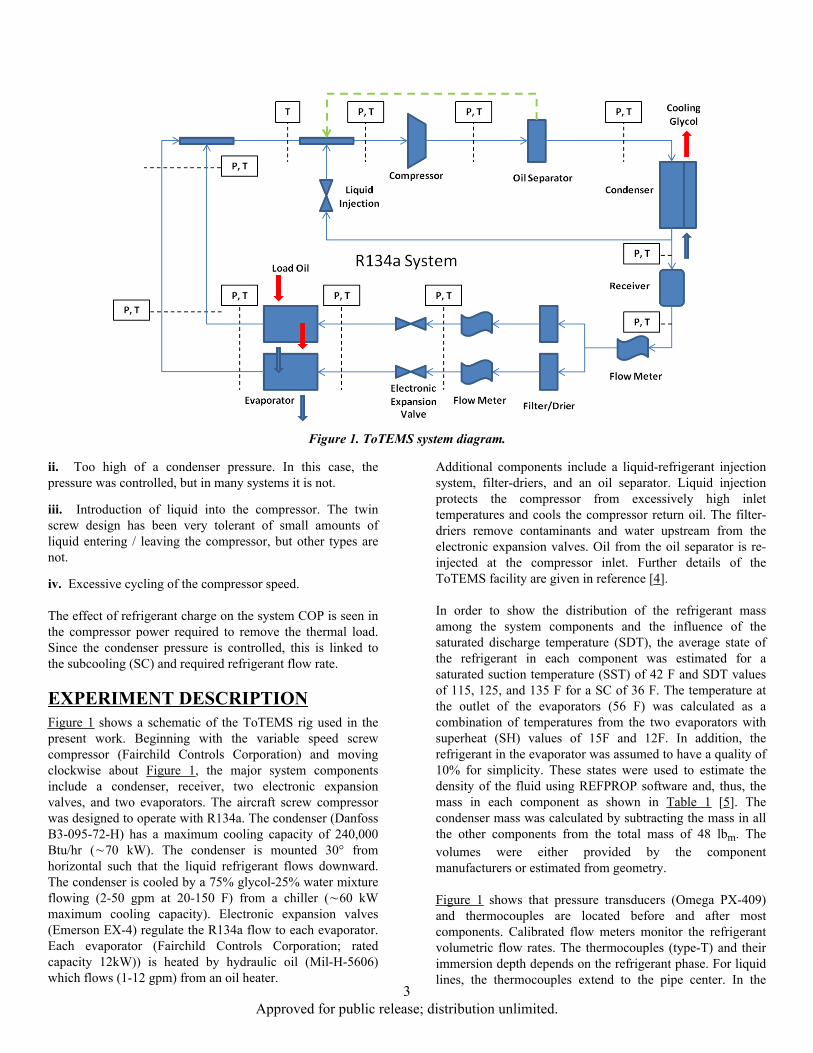
EXPERIMENT DESCRIPTIONFigure 1 shows a schematic of the ToTEMS rig used in thepresent work. Beginning with the variable speed screwcompressor (Fairchild Controls Corporation) and movingclockwise about Figure 1, the major system componentsinclude a condenser, receiver, two electronic expansionvalves, and two evaporators. The aircraft screw compressorwas designed to operate with R134a. The condenser (DanfossB3-095-72-H) has a maximum cooling capacity of 240,000Btu/hr (∼70 kW). The condenser is mounted 30° fromhorizontal such that the liquid refrigerant flows downward.The condenser is cooled by a 75% glycol-25% water mixtureflowing (2-50 gpm at 20-150 F) from a chiller (∼60 kWmaximum cooling capacity). Electronic expansion valves(Emerson EX-4) regulate the R134a flow to each evaporator.Each evaporator (Fairchild Controls Corporation; ratedcapacity 12kW)) is heated by hydraulic oil (Mil-H-5606)which flows (1-12 gpm) from an oil heater.
Additional components include a liquid-refrigerant injectionsystem, filter-driers, and an oil separator. Liquid injectionprotects the compressor from excessively high inlettemperatures and cools the compressor return oil. The filter-driers remove contaminants and water upstream from theelectronic expansion valves. Oil from the oil separator is re-injected at the compressor inlet. Further details of theToTEMS facility are given in reference [4].
In order to show the distribution of the refrigerant massamong the system components and the influence of thesaturated discharge temperature (SDT), the average state ofthe refrigerant in each component was estimated for asaturated suction temperature (SST) of 42 F and SDT valuesof 115, 125, and 135 F for a SC of 36 F. The temperature atthe outlet of the evaporators (56 F) was calculated as acombination of temperatures from the two evaporators withsuperheat (SH) values of 15F and 12F. In addition, therefrigerant in the evaporator was assumed to have a quality of10% for simplicity. These states were used to estimate thedensity of the fluid using REFPROP software and, thus, themass in each component as shown in Table 1 [5]. Thecondenser mass was calculated by subtracting the mass in allthe other components from the total mass of 48 lbm. Thevolumes were either provided by the componentmanufacturers or estimated from geometry.
Figure 1 shows that pressure transducers (Omega PX-409)and thermocouples are located before and after mostcomponents. Calibrated flow meters monitor the refrigerantvolumetric flow rates. The thermocouples (type-T) and theirimmersion depth depends on the refrigerant phase. For liquidlines, the thermocouples extend to the pipe center. In the
Figure 1. ToTEMS system diagram.
3 Approved for public release; distribution unlimited.

vapor lines near the evaporators, the thermocouples aremounted within tees that are ½″ outside the pipe diameter.The tees prevent undesirable liquid droplet impingementwhich would bias the measurement. Seven independentcontrol routines are used in the ToTEMS and includecondenser temperature control, evaporator SH, compressorspeed, compressor inlet SH (liquid injection), and evaporatoroil flow and heat load. Lastly, Table 2 lists the range andaccuracy for the pressure transducers, thermocouples, andflow meters.
Experimental ProceduresThe independent variables selected for study were therefrigerant mass, heater power, and SDT. In preliminaryexperiments, a charge of 45.5 lbm provided acceptableoperation with a SDT of 125 F and, thus, was selected as themidrange value for the refrigerant mass of the system. Fourmasses of refrigerant were used in the experiments: 40.5, 43,45.5, and 48 lbm. Figure 2a shows how the imposedevaporator thermal load (step and sinusoidal variationbetween 36 and 51%) and SDT (step changes of 115, 125,and 135 F) varied with time in the experiments. Figure 2b isan enlarged view of the period between 0 and 6000s. Eachsegment of the variation in thermal load had a duration of 900s (Figure 2b). The SDT affects the liquid level and SC at the
condenser which may be influenced by the system mass. Themeasured dependent variables are the evaporator oil inlet andoutlet temperatures, DC voltage and current supplied to thecompressor, refrigerant temperatures across the evaporators,and condenser exit refrigerant temperature. These variablesare used to calculate COP, SC, and refrigerant SH at theevaporator exit. The refrigerant saturation temperaturenecessary for determination of SC and SH was estimatedusing REFPROP together with the measured pressure [5].One evaporator was run with a constant oil-thermal load of6kW while the other had a time-varying load of either 6.6,9.3, or 12kW. The set point for the evaporator oil exittemperature was held constant. The superheat set point of oneevaporator was 15 F and, the other was 12 F. Although thereare two evaporators in the system, the compressor effectivelytreats them as a single load in the current experiments. Theglycol-water mixture temperature at the condenser inlet wasalways 80 F.
Figure 3 represents the operating envelope for ToTEMS.Near the center of the envelope, the dashed vertical lineindicates the three SDT settings that were used. Thehorizontal lines indicate the short term transient low pressureside SST. Figure 3 shows that the actual operating envelopeis larger than the SDT and SST used in these tests. In futurework, we will increase the range of the experiments.
Table 1. Component volumes and estimated mass for a 48 lbm refrigerant charge.
Table 2. Instrumentation accuracy and range.
4 Approved for public release; distribution unlimited.

A reference state of 125 F SDT, 42.5 F SST, 77.5% load with15 F SH setpoint at evaporator 1, and 100% load with 12 FSH setpoint at evaporator 2 was used for testing. Thisreference state was repeated between all test conditionsdiscussed above and below.
Figure 2. Testing profile for ToTEMS using four refrigerant masses (40.5, 43, 45.5, and 48 lbm) showing (a) changes in SDTand thermal load and (b) enlarged view of the period between 0 and 6000 s.
Figure 3. Representative ToTEMS compressor operatingenvelope. The horizontal (green and blue dashed) lines
represent the SST range of values treated, and thevertical (black dashed) line is the SDT range considered.
RESULTS AND DISCUSSIONExperiments were performed using the ToTEMS to assess thepotential for using the SC, COP, and SH as insitu means ofmonitoring the refrigerant mass and to also assess what is anacceptable system mass particularly for transients. Theexperimental data in the following figures was recorded withall system PID controls active to maintain the desired setpoints.
5 Approved for public release; distribution unlimited.
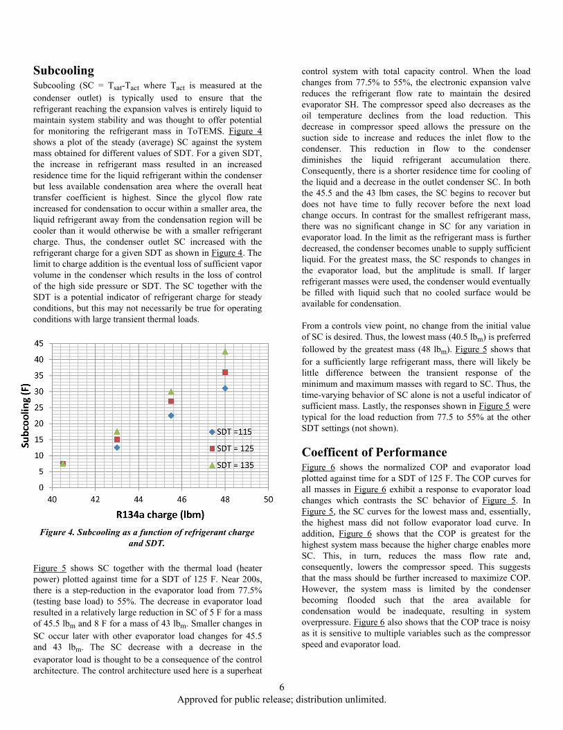
SubcoolingSubcooling (SC = Tsat-Tact where Tact is measured at thecondenser outlet) is typically used to ensure that therefrigerant reaching the expansion valves is entirely liquid tomaintain system stability and was thought to offer potentialfor monitoring the refrigerant mass in ToTEMS. Figure 4shows a plot of the steady (average) SC against the systemmass obtained for different values of SDT. For a given SDT,the increase in refrigerant mass resulted in an increasedresidence time for the liquid refrigerant within the condenserbut less available condensation area where the overall heattransfer coefficient is highest. Since the glycol flow rateincreased for condensation to occur within a smaller area, theliquid refrigerant away from the condensation region will becooler than it would otherwise be with a smaller refrigerantcharge. Thus, the condenser outlet SC increased with therefrigerant charge for a given SDT as shown in Figure 4. Thelimit to charge addition is the eventual loss of sufficient vaporvolume in the condenser which results in the loss of controlof the high side pressure or SDT. The SC together with theSDT is a potential indicator of refrigerant charge for steadyconditions, but this may not necessarily be true for operatingconditions with large transient thermal loads.
Figure 4. Subcooling as a function of refrigerant chargeand SDT.
Figure 5 shows SC together with the thermal load (heaterpower) plotted against time for a SDT of 125 F. Near 200s,there is a step-reduction in the evaporator load from 77.5%(testing base load) to 55%. The decrease in evaporator loadresulted in a relatively large reduction in SC of 5 F for a massof 45.5 lbm and 8 F for a mass of 43 lbm. Smaller changes inSC occur later with other evaporator load changes for 45.5and 43 lbm. The SC decrease with a decrease in theevaporator load is thought to be a consequence of the controlarchitecture. The control architecture used here is a superheat
control system with total capacity control. When the loadchanges from 77.5% to 55%, the electronic expansion valvereduces the refrigerant flow rate to maintain the desiredevaporator SH. The compressor speed also decreases as theoil temperature declines from the load reduction. Thisdecrease in compressor speed allows the pressure on thesuction side to increase and reduces the inlet flow to thecondenser. This reduction in flow to the condenserdiminishes the liquid refrigerant accumulation there.Consequently, there is a shorter residence time for cooling ofthe liquid and a decrease in the outlet condenser SC. In boththe 45.5 and the 43 lbm cases, the SC begins to recover butdoes not have time to fully recover before the next loadchange occurs. In contrast for the smallest refrigerant mass,there was no significant change in SC for any variation inevaporator load. In the limit as the refrigerant mass is furtherdecreased, the condenser becomes unable to supply sufficientliquid. For the greatest mass, the SC responds to changes inthe evaporator load, but the amplitude is small. If largerrefrigerant masses were used, the condenser would eventuallybe filled with liquid such that no cooled surface would beavailable for condensation.
From a controls view point, no change from the initial valueof SC is desired. Thus, the lowest mass (40.5 lbm) is preferredfollowed by the greatest mass (48 lbm). Figure 5 shows thatfor a sufficiently large refrigerant mass, there will likely belittle difference between the transient response of theminimum and maximum masses with regard to SC. Thus, thetime-varying behavior of SC alone is not a useful indicator ofsufficient mass. Lastly, the responses shown in Figure 5 weretypical for the load reduction from 77.5 to 55% at the otherSDT settings (not shown).
Coefficent of PerformanceFigure 6 shows the normalized COP and evaporator loadplotted against time for a SDT of 125 F. The COP curves forall masses in Figure 6 exhibit a response to evaporator loadchanges which contrasts the SC behavior of Figure 5. InFigure 5, the SC curves for the lowest mass and, essentially,the highest mass did not follow evaporator load curve. Inaddition, Figure 6 shows that the COP is greatest for thehighest system mass because the higher charge enables moreSC. This, in turn, reduces the mass flow rate and,consequently, lowers the compressor speed. This suggeststhat the mass should be further increased to maximize COP.However, the system mass is limited by the condenserbecoming flooded such that the area available forcondensation would be inadequate, resulting in systemoverpressure. Figure 6 also shows that the COP trace is noisyas it is sensitive to multiple variables such as the compressorspeed and evaporator load.
6 Approved for public release; distribution unlimited.

The peak-to-peak variation of the COP trace for the smallestmass is large relative to those of the other masses. Forexample between 2000 and 3000 s, the root-mean-square(RMS) value of the COP curve for the lowest mass is 0.0102while the other three masses have RMS values in the range0.0070 to 0.0076. The large root mean square value is an
indication of bounded behavior that is becoming difficult tocontrol. Thus, Figure 6 shows that the large peak-to-peakvariation in the COP offers a reasonable indication ofinadequate refrigerant mass and has the potential to be usedas an insitu indicator of refrigerant mass. Between 200 and1100s, the evaporator load decreases as does the COP curvesfor all masses. In addition between 2000 and 2900 s, the COP
Figure 5. SC for four refrigerant masses for an SDT of 125 F and time-varying thermal load.
Figure 6. Normalized COP for four system masses and a time-varying thermal load for an SDT of 125 F.
7 Approved for public release; distribution unlimited.
curves for the two greatest masses increase as the evaporatorload increases, but the COP curves for the two smallestmasses decrease in this range. At present, we are continuingour analysis to understand this behavior.
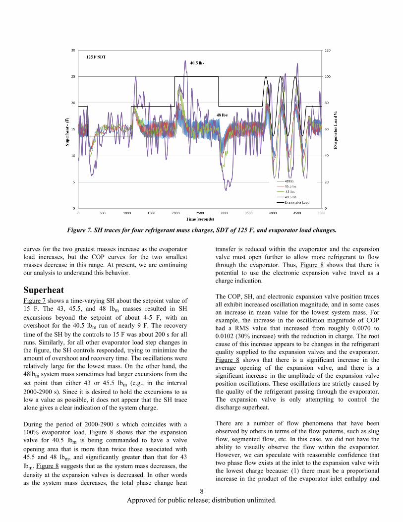
SuperheatFigure 7 shows a time-varying SH about the setpoint value of15 F. The 43, 45.5, and 48 lbm masses resulted in SHexcursions beyond the setpoint of about 4-5 F, with anovershoot for the 40.5 lbm run of nearly 9 F. The recoverytime of the SH by the controls to 15 F was about 200 s for allruns. Similarly, for all other evaporator load step changes inthe figure, the SH controls responded, trying to minimize theamount of overshoot and recovery time. The oscillations wererelatively large for the lowest mass. On the other hand, the48lbm system mass sometimes had larger excursions from theset point than either 43 or 45.5 lbm (e.g., in the interval2000-2900 s). Since it is desired to hold the excursions to aslow a value as possible, it does not appear that the SH tracealone gives a clear indication of the system charge.
Figure 7. SH traces for four refrigerant mass charges, SDT of 125 F, and evaporator load changes.
During the period of 2000-2900 s which coincides with a100% evaporator load, Figure 8 shows that the expansionvalve for 40.5 lbm is being commanded to have a valveopening area that is more than twice those associated with45.5 and 48 lbm, and significantly greater than that for 43lbm. Figure 8 suggests that as the system mass decreases, thedensity at the expansion valves is decreased. In other wordsas the system mass decreases, the total phase change heat
transfer is reduced within the evaporator and the expansionvalve must open further to allow more refrigerant to flowthrough the evaporator. Thus, Figure 8 shows that there ispotential to use the electronic expansion valve travel as acharge indication.
The COP, SH, and electronic expansion valve position tracesall exhibit increased oscillation magnitude, and in some casesan increase in mean value for the lowest system mass. Forexample, the increase in the oscillation magnitude of COPhad a RMS value that increased from roughly 0.0070 to0.0102 (30% increase) with the reduction in charge. The rootcause of this increase appears to be changes in the refrigerantquality supplied to the expansion valves and the evaporator.Figure 8 shows that there is a significant increase in theaverage opening of the expansion valve, and there is asignificant increase in the amplitude of the expansion valveposition oscillations. These oscillations are strictly caused bythe quality of the refrigerant passing through the evaporator.The expansion valve is only attempting to control thedischarge superheat.
There are a number of flow phenomena that have beenobserved by others in terms of the flow patterns, such as slugflow, segmented flow, etc. In this case, we did not have theability to visually observe the flow within the evaporator.However, we can speculate with reasonable confidence thattwo phase flow exists at the inlet to the expansion valve withthe lowest charge because: (1) there must be a proportionalincrease in the product of the evaporator inlet enthalpy and
8 Approved for public release; distribution unlimited.

the refrigerant mass flow rate or the mean expansion valveopening would not have increased; (2) the magnitude of thesuperheat oscillation and the expansion valve movementshows there is an inconsistency in the bulk quality of the fluidpassing through the expansion valve. These valves arevolumetric flow devices and, given that the experimentmaintained a near constant pressure drop across the valve,then the only explanation is there is a change in the effectivedensity of the fluid passing through the expansion valve.
For a fixed SDT, Table 3 shows that the enthalpy decreasesabout 20% as the system mass increases. However, Figure 9shows that the mean valve position changes as much as 100%of the set point (i.e., twice the valve opening) for a systemmass of 40.5 lbm. Therefore, the average density of the fluidmust be changing roughly by a factor of 2. It is very likelythat the refrigerant entering the electronic expansion valve isinside the two phase region or very near the saturation line.Additional evidence that this is the appropriate conclusion isshown in Figure 9 where the mean value of the expansionvalve opening decreases with the 40.5 pound charge as theSDT is increased. As the SDT increases, the pressureincreases, and the expansion valve inlet enthalpy increases.
Figure 8. Percent opening of an expansion valve for different system masses and evaporator loads, SDT = 125 F.
Thus, further indicating that at the lower charge and lowerSDT the expansion valve inlet is very near or inside the twophase region. One implication of low charge on operabilitycould be a restriction in the minimum SDT. The ToTEMSonly had difficulty controlling superheat with 40.5 pounds ofcharge and SDT below 135F.
Table 3. Enthalpy at the expansion valve inlet.
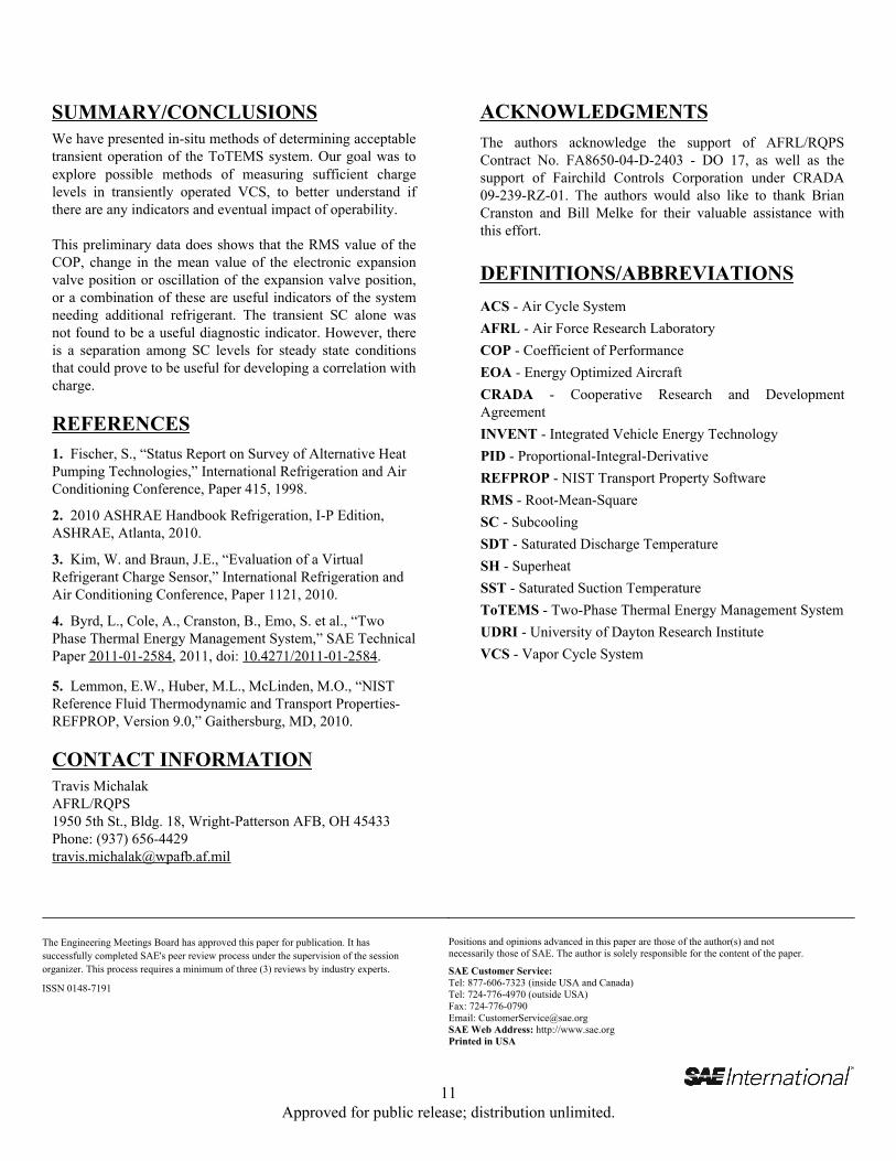
Figures 8 and 9 show that the change in the mean value of theexpansion valve position or oscillation of the expansion valveposition is a useful indicator of the system requiringadditional refrigerant. Figure 10 shows that the evaporator oildischarge temperature was held within ± 2 F during allexperiments. These relatively small temperature excursionsshow that the system was still meeting its primaryrequirements, but intermediate control parameters (such asSH) were only marginal.
9 Approved for public release; distribution unlimited.
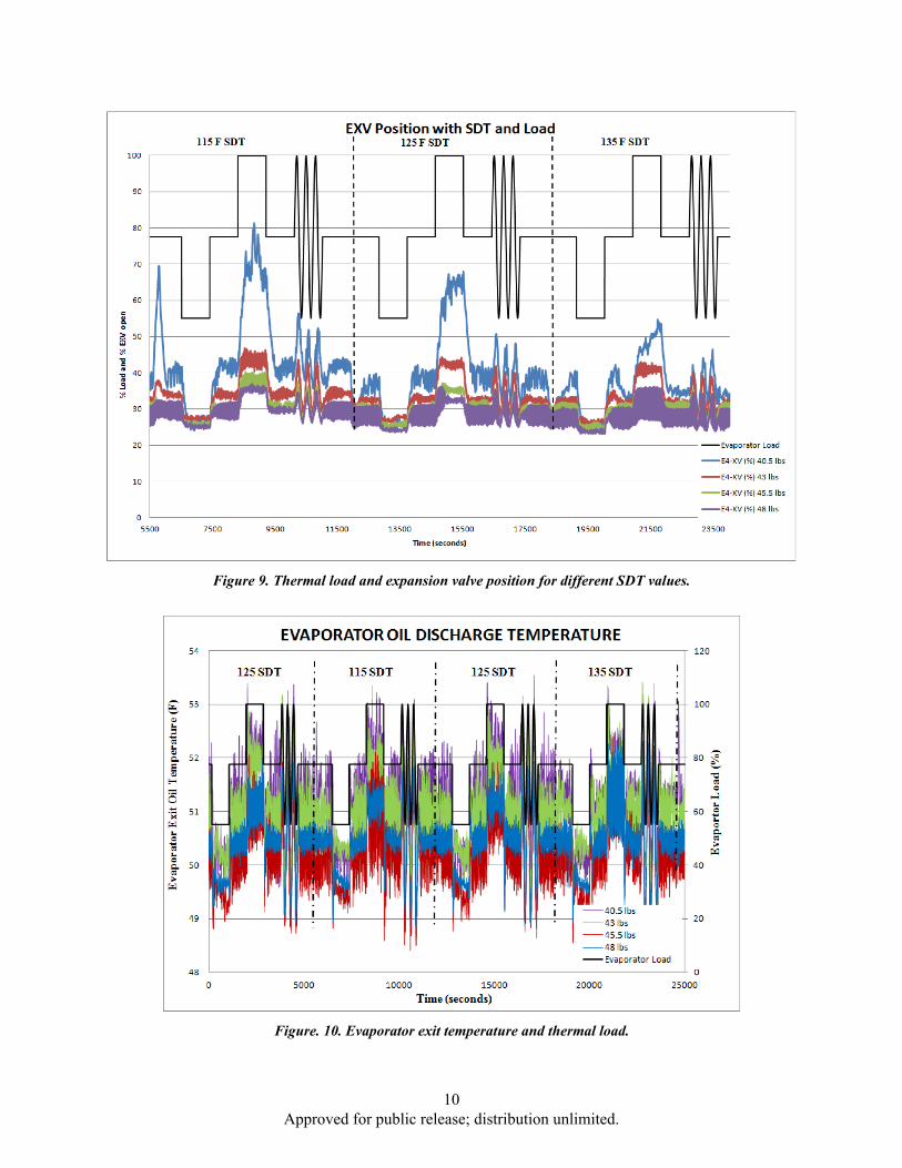
Figure 9. Thermal load and expansion valve position for different SDT values.
Figure. 10. Evaporator exit temperature and thermal load.
10 Approved for public release; distribution unlimited.
The Engineering Meetings Board has approved this paper for publication. It hassuccessfully completed SAE's peer review process under the supervision of the sessionorganizer. This process requires a minimum of three (3) reviews by industry experts.
ISSN 0148-7191
Positions and opinions advanced in this paper are those of the author(s) and notnecessarily those of SAE. The author is solely responsible for the content of the paper.
SAE Customer Service:Tel: 877-606-7323 (inside USA and Canada)Tel: 724-776-4970 (outside USA)Fax: 724-776-0790Email: [email protected] Web Address: http://www.sae.orgPrinted in USA
ACKNOWLEDGMENTSThe authors acknowledge the support of AFRL/RQPSContract No. FA8650-04-D-2403 - DO 17, as well as thesupport of Fairchild Controls Corporation under CRADA09-239-RZ-01. The authors would also like to thank BrianCranston and Bill Melke for their valuable assistance withthis effort.
DEFINITIONS/ABBREVIATIONSACS - Air Cycle SystemAFRL - Air Force Research LaboratoryCOP - Coefficient of PerformanceEOA - Energy Optimized AircraftCRADA - Cooperative Research and DevelopmentAgreementINVENT - Integrated Vehicle Energy TechnologyPID - Proportional-Integral-DerivativeREFPROP - NIST Transport Property SoftwareRMS - Root-Mean-SquareSC - SubcoolingSDT - Saturated Discharge TemperatureSH - SuperheatSST - Saturated Suction TemperatureToTEMS - Two-Phase Thermal Energy Management SystemUDRI - University of Dayton Research InstituteVCS - Vapor Cycle System
SUMMARY/CONCLUSIONSWe have presented in-situ methods of determining acceptabletransient operation of the ToTEMS system. Our goal was toexplore possible methods of measuring sufficient chargelevels in transiently operated VCS, to better understand ifthere are any indicators and eventual impact of operability.
This preliminary data does shows that the RMS value of theCOP, change in the mean value of the electronic expansionvalve position or oscillation of the expansion valve position,or a combination of these are useful indicators of the systemneeding additional refrigerant. The transient SC alone wasnot found to be a useful diagnostic indicator. However, thereis a separation among SC levels for steady state conditionsthat could prove to be useful for developing a correlation withcharge.
REFERENCES1. Fischer, S., “Status Report on Survey of Alternative HeatPumping Technologies,” International Refrigeration and AirConditioning Conference, Paper 415, 1998.
2. 2010 ASHRAE Handbook Refrigeration, I-P Edition,ASHRAE, Atlanta, 2010.
3. Kim, W. and Braun, J.E., “Evaluation of a VirtualRefrigerant Charge Sensor,” International Refrigeration andAir Conditioning Conference, Paper 1121, 2010.
4. Byrd, L., Cole, A., Cranston, B., Emo, S. et al., “TwoPhase Thermal Energy Management System,” SAE TechnicalPaper 2011-01-2584, 2011, doi: 10.4271/2011-01-2584.
5. Lemmon, E.W., Huber, M.L., McLinden, M.O., “NISTReference Fluid Thermodynamic and Transport Properties-REFPROP, Version 9.0,” Gaithersburg, MD, 2010.
CONTACT INFORMATIONTravis MichalakAFRL/RQPS1950 5th St., Bldg. 18, Wright-Patterson AFB, OH 45433Phone: (937) [email protected]
11 Approved for public release; distribution unlimited.