IMU Future Issues
123
BNA - 051 SHIP MANOEUVRING AND FUTURE ISSUES Block 3 FUTURE ISSUES UNIT 7 Ballast Water and Sediment Management 5 UNIT 8 Marpol Annexure IV 2 5 UNIT 9 Marpol Annexure VI - Part - A: Prevention of Air Pollution 45 UNIT 10 Marpol Annexure VI - Part - B: Regulation for the Prevention of Air Pollution from Ships 69 UNIT 11 Fuel Conservation 8 9 UNIT 12 Doubl e Hulls 1 07 UNIT 13 Places of Refug e 1 1 7 UNIT 14 Green Pass port 1 2 5
Transcript of IMU Future Issues

8/6/2019 IMU Future Issues
http://slidepdf.com/reader/full/imu-future-issues 1/123
BNA - 051
SHIP MANOEUVRING
AND FUTURE ISSUES
Block
3FUTURE ISSUES
UNIT 7
Ballast Water and Sediment Management 5
UNIT 8
Marpol Annexure IV 25
UNIT 9
Marpol Annexure VI - Part - A: Prevention of Air Pollution 45
UNIT 10
Marpol Annexure VI - Part - B: Regulation for the Prevention of
Air Pollution from Ships 69
UNIT 11
Fuel Conservation 89
UNIT 12
Double Hulls 107
UNIT 13
Places of Refuge 117
UNIT 14
Green Passport 125

8/6/2019 IMU Future Issues
http://slidepdf.com/reader/full/imu-future-issues 2/123
FUTURE ISSUES
This block has 8 units.
Unit 14 "Green Passport" explains about the issues related to ship dismantling and
recycling as per IMO guidelines.
Unit 13 "Place of Refuge" deals with the guidelines on providing place of refuse to a ship
in need of refuge. These include actions that need to be taken by masters of ship and expectedactions of coastal states in providing place of refuge.
Unit-12 "Double Hull" deals with regulations related to double hull protection of oil
tanks on all ships as per IMO guidelines. In unit six incidents of bunker oil spills are
described.
Unit 11 "Fuel Conservation" presents an overview of worldwide energy recourses and
explains various forms of non-conventional energy resources. The factors that affect on
board ships fuel consumption and seeps towards fuel conservation are briefly presented in
this unit.
Unit 9 and Unit 10 lists the provisions given in Marpol Annexure-Vl dealing with the
prevention and control of air pollution from ships.
Unit 8 enumerates the provisions prescribed in Marpol Annexure-IV that provides
regulations for the prevention of pollution by sewage from shipsUnit 7 "Ballast Water and Sediment Management deals with the recording and reporting
Managemen
for ballast water management for ships and port states and various actions that
need to be taken under different circumstances. Guidelines on safety aspects of ballast
water exchange at sea are briefly listed.

8/6/2019 IMU Future Issues
http://slidepdf.com/reader/full/imu-future-issues 3/123
8/6/2019 IMU Future Issues
http://slidepdf.com/reader/full/imu-future-issues 4/123
5
NIT 7 BALLAST WATER AND SEDIMENT
MANAGEMENT
ructure
7.1 Introduction
Objective
7.2 Definitions
7.3 Application
7.4 Guideline Objectives and Background
7.5 Dissemination of Information
7.6 Training and Education
7.7 Procedures for Ships and Port States
7.8 Recording and Reporting Procedures
7.9 Ships' Operational Procedures
7.10 Port State Considerations
7.11 Enforcement and Monitoring by Port States
7.12 Future Considerations in Relation to Ballast Water Exchange
7.13 Ballast System Design
7.14 Ballast Water Report Form (Appendix 1)
7.15 Guidance on Safety Aspects of Ballast Water Exchange at Sea
(Appendix H)
7.16 Impacts of Some of the Worst Invasive Aquatic Species
7.17 Summary
1 INTRODUCTION
udies carried out in several countries have shown that many species of bacteria, plants,d animals can survive in a viable form in the ballast water and'sediment carried inps, even after journeys of several months' duration. Subsequent discharge of ballast watersediment into the waters of port States may result in the establishment of harmful aquaticganisms and pathogens which may pose threats to indigenous human, animal and plant
e, and the marine environment. Although other media have been identified as beingponsible for transferring organisms between geographically separated water bodies,llast water discharge from ships appears to have been among the mostominent.
e potential for ballast water discharge to cause harm has been recognised not only byInternational Maritime Organization but also by the World Health Organization,ich is concerned about the role of ballast water as a medium for the spreading of demic disease bacteria.
ese Guidelines are not to be regarded as a certain solution to the problem. Rather, eachrt of them should be viewed as a tool which, if correctly applied, will help to minimize the
ks associated with ballast water discharge. As scientific and technological advances areade, the Guidelines will be refined to enable the risk to be more adequatelydressed. In the interim, port States, flag States and other parties that can assist in

8/6/2019 IMU Future Issues
http://slidepdf.com/reader/full/imu-future-issues 5/123
6
Future Issues mitigating this problem should exercise due care and diligence in an effort to conform tothe maximum extent possible with the Guidelines.
The selection of appropriate methods of risk minimization will depend upon several factors,including the type or types of organisms being targeted, the level of risk involved, itsenvironmental acceptability, the economic and ecological costs involved and the safety of ships.
Objectives
After studying this unit you should be able to state
• the operational procedures to be followed by ships when taking in ordischarging ballast water,
• the procedures which are followed by port states,
• safety aspects related to the ballast water management and
• contents of the Ballast Water report form.
7.2 DEFINITIONS
For the purposes of these Guidelines, the following definitions apply:
Administration means the Government of the State under whose authority the ship isoperating.
Convention means MARPOL 73/78 (International Convention for the Prevention of Pollution from Ships, 1973, and the Protocol of 1978 related thereto).
Member States means States that are Members of the International MaritimeOrganization.
Organization means the International Maritime Organization (IMO).
Port State authority means any official or organisation authorized by the Government of a
port State to administer guidelines or enforce standards and regulations relevant to theimplementation of national and international shipping control measures.
Treatment means a process or mechanical, physical, chemical or biological method to kill,remove or render infertile, harmful or potentially harmful organisms within ballast water.
7.3 APPLICATION
The Guidelines are directed to Member States and can apply to all ships; however, a portState authority shall determine the extent to which they do apply.
7.4 GUIDELINE OBJECTIVES AND BACKGROUND
The objectives of these Guidelines, developed under technical and scientific guidance,are intended to assist Governments and appropriate authorities, ship masters, operators andowners, and port authorities, as well as other interested parties, in minimizing the risk of introducing harmful aquatic organisms and pathogens from ships' ballast water andassociated sediments while protecting ships' safety.
The Guidelines allow port States to exempt ships within the area under their jurisdictionfrom part or all of the relevant provisions. Notwithstanding, any administration wishing toapply restrictions to ballast water operations should still follow these Guidelines, whendeveloping legislation or procedures.

8/6/2019 IMU Future Issues
http://slidepdf.com/reader/full/imu-future-issues 6/123
7
Ballast Water andSediment Management
In order that the Guidelines may be implemented in a standard and uniform manner, allMember State Governments, ship operators, other appropriate authorities and interestedparties are requested to apply these Guidelines.
7.5 DISSEMINATION OF INFORMATION
7.5.1 Administrations are encouraged to maintain and exchange information relevant tothese Guidelines through the Organization. Accordingly, administrations are
encouraged to provide the Organization with the following:• Information on severe outbreaks or infestations of harmful aquatic organisms
which may pose a risk;
• Copies of current domestic laws and regulations;
• Technical and research information;
• Education materials (such as audio and video tapes) and printed materials;
• Location and terms of use of alternative exchange zones, contingencystrategies, availability of shore reception facilities, fees, etc.
7.5.2 Member States, applying ballast water and sediment discharge procedures, should
notify the Organization of specific requirements and provide to the Organization,for the information of other Member States and non-governmental organizations,copies of any regulations, standards, exemptions or guidelines being applied.Verification and detailed information concerning port State requirements shouldbe obtained by the ship prior to arrival.
7.5.3 Port State authorities should provide the widest possible distribution of information on ballast water and sediment management and treatmentrequirements that are being applied to shipping. Failure to do so may lead tounnecessary delays for ships seeking entry to port States.
7.5.4 Shipping organizations and ships' managers should be familiar with the requirements
of port State authorities with respect to ballast water and sediment managementand treatment procedures, including information that will be needed to obtain entryclearance.
7.5.5 Member States are invited to provide the Organization with details of any researchand development studies that they carry out with respect to the impact and controlof harmful aquatic organisms and pathogens in ships' ballast water and sediment.
'7.5.6 Member States should provide to the Organization details of records describingreasons why existing requirements could not be complied with, e.g. force majeure,heavy weather, failure of equipment, or lack of information concerning port Staterequirements.
7.6 TRAINING AND EDUCATION
7.6.1 Training for ships' masters and crews as appropriate should include instructionson the application of ballast water and sediment management and treatmentprocedures, based upon the information contained in these Guidelines. Instructionshould also be provided on the maintenance of appropriate records and logs.Governments should ensure that their marine training organizations include this inthe contents of their syllabus.
7.6.2 The application of processes and procedures concerning ballast water managementare currently at the core of the solution to minimize the introduction of harmfulaquatic organisms and pathogens.

8/6/2019 IMU Future Issues
http://slidepdf.com/reader/full/imu-future-issues 7/123
8
Future Issues 7.6.3 Governments are encouraged to include knowledge of duties regarding thecontrol of pollution of the sea by harmful aquatic organisms and pathogens intheir training requirements for certificates.
7.7 PROCEDURES FOR SHIPS AND PORT STATES
7.7.1 Procedures for Ships
7.7.1.1 Every ship that carries ballast water should be provided with a ballast watermanagement plan to assist in the minimization of transfer of harmful aquaticorganisms and pathogens. The intent of the plan should be to provide safe andeffective procedures for ballast water management.
7.7.1.2 The ballast water management plan should be specific to each ship.
7.7.1.3 The ballast water management plan should be included in the ship's operationaldocumentation. Such a plan should address, inter alias
• relevant parts of these Guidelines;
• approval documentation relevant to treatment equipment;
•
an indication of records required; and• the location of possible sampling points.
7.7.2 Procedures for Port States
7.7.2.1 Reception and treatment facilities should be made available for theenvironmentally safe disposal of ballast tank sediments.
7.7.2.2 Discharge of ship's ballast water into port reception and/or treatment facilitiesmay provide an acceptable means of control. Port State authorities wishing toutilize this strategy should ensure that the facilities are adequate.
7.8 RECORDING AND REPORTING PROCEDURES
7.8.1 Procedures for Ships
7.8.1.1 Where a port State authority requires that specific ballast water procedures and/ortreatment option(s) be undertaken, and due to weather, sea conditions oroperational impracticability such action cannot be taken, the master should reportthis fact to the port State authority as soon as possible and, where appropriate, priorto entering seas under its jurisdiction.
7.8.1.2 To facilitate the administration of ballast water management and treatmentprocedures on board each ship, a responsible officer should be appointed to
maintain appropriate records and to ensure that ballast water management and/ortreatment procedures are followed and recorded.
7.8.1.3 When taking in or discharging ballast water, as a minimum, the dates, geographicallocations, ship's tank(s) and cargo holds, ballast water temperature and salinity aswell as the amount of ballast water loaded or discharged should be recorded. Asuitable format is shown in appendix 1. The record should be made available to theport State authority.
7.8.1.4 The location and suitable access points for sampling ballast or sediment shouldbe described in the ship's ballast water management plan. This will allow crewmembers to provide maximum assistance when officers of the port State authority
require a sample of the ballast water or sediment.

8/6/2019 IMU Future Issues
http://slidepdf.com/reader/full/imu-future-issues 8/123
9
Ballast Water andSediment Management
7.8.2 Procedures for port States
7.8.2.1 Consistent with 7.5.2 above, port States should provide ships with the followinginformation:
• DetaiIs of their requirements concerning ballast water management;
Iocation and terms of use of alternative exchange zones;Any
• other port contingency arrangements; and
• The availability, location, capacities of and applicable fees relevant toreception facilities that are being provided for the environmentally safedisposal of ballast water and associated sediment.
7.8.2.2 To assist ships in applying the precautionary practices described in 7.9.1.1 below,port States should inform local agents and/or the ship of areas and situationswhere the uptake of ballast water should be minimized, such as:
• Areas with outbreaks, infestations or known populations of harmfulorganisms and pathogens;
Z:1
Areas with current phytoplankton blooms (algal blooms, such as red tides);
Nearby sewage outfalls;
• Nearby dredging operations;
When a tidal stream is known to be the more turbid; and
Areas where tidal flushing is known to be poor.
7.9 SHIPS' OPERATIONAL PROCEDURES
7.9.1 Precautionary Practices
7.9.1.1 Minimizing Uptake of Harmful Aquatic Organisms, Pathogens and Sediments
When loading ballast, every effort should be made to avoid the uptake of potentially harmful aquatic organisms, pathogens and sediment that may containsuch organisms. The uptake of ballast water should be minimized or, wherepracticable, avoided in areas and situations such as:
Areas identified by the port State in connection with advice relating to7.8.2.2 above:
In darkness when bottom-dwelling organisms may rise up in the watercolumn;
In very shallow water; or
Where propellers may stir up sediment.
7.9.1.2 Removing ballast sediment on a timely basis
Where practicable, routine cleaning of the ballast tank to remove sedimentsshould be carried out in mid-ocean or under controlled arrangements in port ordry dock, in accordance with the provisions of the ship's ballast watermanagement plan.
7.9.1.3 Avoiding unnecessary discharge of ballast water
If it is necessary to take on and discharge ballast water in the same port tofacilitate safe cargo operations, care should be taken to avoid unnecessarydischarge of-ballast water that has been taken up in another port.
8/6/2019 IMU Future Issues
http://slidepdf.com/reader/full/imu-future-issues 9/123
10
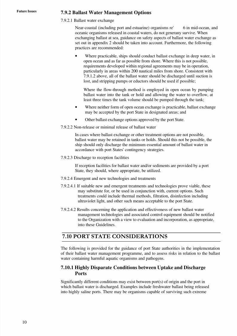
Future Issues 7.9.2 Ballast Water Management Options
7.9.2.1 Ballast water exchange
Near-coastal (including port and estuarine) organisms re' 6 in mid-ocean, andoceanic organisms released in coastal waters, do not generany survive. Whenexchanging ballast at sea, guidance on safety aspects of ballast water exchange asset out in appendix 2 should be taken into account. Furthermore, the followingpractices are recommended:
• Where practicable, ships should conduct ballast exchange in deep water, inopen ocean and as far as possible from shore. Where this is not possible,requirements developed within regional agreements may be in operation,particularly in areas within 200 nautical miles from shore. Consistent with7.9.1.2 above, all of the ballast water should be discharged until suction islost, and stripping pumps or eductors should be used if possible;
Where the flow-through method is employed in open ocean by pumpingballast water into the tank or hold and allowing the water to overflow, atleast three times the tank volume should be pumped through the tank;
• Where neither form of open ocean exchange is practicable, ballast exchangemay be accepted by the port State in designated areas; and
• Other ballast exchange options approved by the port State.
7.9.2.2 Non-release or minimal release of ballast water
In cases where ballast exchange or other treatment options are not possible,ballast water may be retained in tanks or holds. Should this not be possible, theship should only discharge the minimum essential amount of ballast water inaccordance with port States' contingency strategies.
7.9.2.3 Discharge to reception facilities
If reception facilities for ballast water and/or sediments are provided by a portState, they should, where appropriate, be utilized.
7.9.2.4 Emergent and new technologies and treatments
7.9.2.4.1 If suitable new and emergent treatments and technologies prove viable, thesemay substitute for, or be used in conjunction with, current options. Suchtreatments could include thermal methods, filtration, disinfection includingultraviolet light, and other such means acceptable to the port State.
7.9.2.4.2 Results concerning the application and effectiveness of new ballast watermanagement technologies and associated control equipment should be notifiedto the Organization with a view to evaluation and incorporation, as appropriate,into these Guidelines.
7.10 PORT STATE CONSIDERATIONS
The following is provided for the guidance of port State authorities in the implementationof their ballast water management programme, and to assess risks in relation to the ballastwater containing harmful aquatic organisms and pathogens.
Z_
7.10.1 Highly Disparate Conditions between Uptake and DischargePorts
Significantly different conditions may exist between port(s) of origin and the port inwhich ballast water is discharged. Examples include freshwater ballast being releasedinto highly saline ports. There may be organisms capable of surviving such extreme
8/6/2019 IMU Future Issues
http://slidepdf.com/reader/full/imu-future-issues 10/123
II
Ballast Water andSediment Management
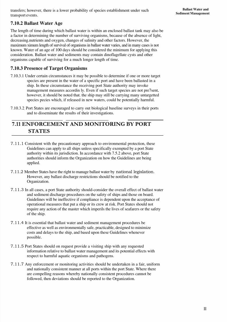
transfers; however, there is a lower probability of species establishment under suchtransport events.
7.10.2 Ballast Water Age
The length of time during which ballast water is within an enclosed ballast tank may also bea factor in determining the number of surviving organisms, because of the absence of light,decreasing.nutrients and oxygen, changes of salinity and other factors. However, themaximum ximum length of survival of organisms in ballast water varies, and in many cases is notknown. Water of an age of 100 days should be considered the minimum for applying this
consideration. Ballast water and sediments may contain dinoflagellate cysts and otherorganisms capable of surviving for a much longer length of time.
7.10.3 Presence of Target Organisms
7.10.3.1 Under certain circumstances it may be possible to determine if one or more targetspecies are present in the water of a specific port and have been ballasted in aship. In these circumstance the receiving port State authority may invokemanagement measures accordin ly. Even if such target species are not pre7sent,however, it should be noted that. the ship may still be carrying many untargettedspecies pecies which, if released in new waters, could be potentially harmful.
7.10.3.2. Port States are encouraged to carry out biological baseline surveys in their ports
and to disseminate the results of their investigations.
7.11 ENFORCEMENT AND MONITORING BY PORT
STATES
7.11.1 Consistent with the precautionary approach to environmental protection, theseGuidelines can apply to all ships unless specifically exempted by a port Stateauthority within its jurisdiction. In accordance with 7.5.2 above, port Stateauthorities should inform the Organization on how the Guidelines are beingapplied.
7.11.2 Member States have the right to manage ballast water by national legislation.However, any ballast discharge restrictions should be notified to theOrganization.
7.11.3 In all cases, a port State authority should-consider the overall effect of ballast waterand sediment discharge procedures on the safety of ships and those on board.Guidelines will be ineffective if compliance is dependent upon the acceptance of operational measures that put a ship or its crew at risk. Port States should notrequire any action of the master which imperils the lives of seafarers or the safetyof the ship.
7.11.4 It is essential that ballast water and sediment management procedures beeffective as well as environmentally safe, practicable, designed to minimizecosts and delays to the ship, and based upon these Guidelines wheneverpossible.
7.11.5 Port States should on request provide a visiting ship with any requestedinformation relative to ballast water management and its potential effects withrespect to harmful aquatic organisms and pathogens.
7.11.7 Any enforcement or monitoring activities should be undertaken in a fair, uniformand nationally consistent manner at all ports within the port State. Where thereare compelling reasons whereby nationally consistent procedures cannot befollowed, then deviations should be reported to the Organization.

8/6/2019 IMU Future Issues
http://slidepdf.com/reader/full/imu-future-issues 11/123
Future Issues
12
7.11.8 Compliance monitoring should be undertaken by port State authorities by, forexample, taking and analysing ballast wafer and sediment samples to test for thecontinued survival of harmful aquatic organisms and pathogens.
7.11.9 Where ballast water or sediment sampling for compliance or effectivenessmonitoring is being undertaken, port State authorities should minimize delays toships when taking such samples.
7.11.10 When sampling for research or compliance monitoring, the port State authorityshould give as much notice as possible to the ship that sampling will occur, to
assist in planning staffing and operational resources.7.11.11 The master has a general obligation to provide reasonable assistance for the
above monitoring which may include provision of officers or crew, provision of the ship's plans, records pertaining to ballast arrangements and detailsconcerning the location of sampling points.
7.11.12 Sampling methods for research and monitoring is the responsibility of theindividual port State. The Organization welcomes information on new orinnovative methods of sampling and/or analysis, and any relevant informationshould be provided to it.
7.11.13 Port State authorities should indicate to the master or responsible officer the
purpose for which a sample is taken (i.e., monitoring, research or enforcement).Results of analyses of samples should be made available to ship's operators onrequest.
7.11.14 Port State authorities may sample or require samples to analyse ballast water andsediment, befog permitting a ship to proceed to discharge its ballast water inenvironmentally sensitive locations. In the event that harmful aquatic organismsor pathogens are found to be present in the samples, a port State's contingencystrategy may be applied.
7.12 FUTURE CONSIDERATIONS IN RELATION TO
BALLAST WATER EXCHANGE
7.12.1 Research Needs
Operational measures such as ballast water exchange may be appropriate in the shortterm; however, there is a clear need for further research. These Guidelines should berevised and adjusted in the light of results concerning new ballast water managementoptions.
7.12.2 Long-Term Evaluation of Safety Aspects in Relation to BallastWater Exchange
Recognizing the need to evaluate the hazards and potential consequences for varioustypes of ships and operations, interested parties should carry out detailed studies andprovide information relevant to:
Experience gained from carrying out ballast water exchange at sea, including anysamples/model procedures;
Operational precautions and procedures implemented to avoid potential hazardsand consequences that may arise during the ballast water exchange at sea;
An evaluation of the safety margins between the actual metacentric height andstresses versus the allowable seagoing limits specified in the approved trim andstability booklet and loading manual, relevant to different types of ships and
loading conditions;

8/6/2019 IMU Future Issues
http://slidepdf.com/reader/full/imu-future-issues 12/123
Ballast Water andSediment Management
Any hazards which may arise due to human element issues relative to the
responsible execution of ballast water exchange at sea in a manner which may not
be fully prudent;
Operational procedures carried out prior to initiating the ballast water exchange at
sea and check points during the exchange;
The extent of training and management necessary to ensure that the process of
ballast water exchange at sea is effectively monitored and controlled on board;
m plan of action to incorporate any unique procedures should an emergency occur
which may affect the exchange of ballast water at sea; and
The decision-making process, taking into account relevant safety matters, including
ship's position, weather conditions, machinery performance, ballast system
inspection and maintenance, crew safety and availability.
7.13 BALLAST SYSTEM DESIGN
Builders, owners and classification societies should take these Guidelines into
onsideration when designing new ships or modifying existing ships.
7.14 BALLAST WATER REPORT FORM (Appendix I)
APPENDIX I
2 io
-aZ Z a
:e
2 0
d
.K
Z
Im
L U
0
Z
LL i s
Z ZPM0
2 <Z
C
orZ
a C n
Z'
'Z
1 , U
,o IL~K
0 0 -
M Z 0
0 Z
0 Z W
L U
C Z cc
5 Z ,
t
5 ,
1; C L 0 1
0 Z
0
to
Z 0 0 0
2 3 .
Z - ' i Z 4 4

8/6/2019 IMU Future Issues
http://slidepdf.com/reader/full/imu-future-issues 13/123
Future Issues7.15 GUIDANCE ON SAFETY ASPECTS OF
BALLAST WATER EXCHANGE AT SEA(Appendix II)
7.15.1 Introduction
7.15.1.1 This document is intended to provide guidance on the safety aspects of ballast
water exchange at sea. The different types of ships which may be required toundertake ballast water exchange at sea make it presently impractical to providespecific guidelines for each ship type. Shipowners are cautioned that theyshould consider the many variables that apply to their ships. Some of thesevariables include type and size of ship, ballast tank configurations andassociated pumping systems, trading routes and associated weather conditions,port State requirements and manning.
7.15.1.2 Ballast water exchange at sea procedures contained in relevant management plansshould be individually assessed for their effectiveness from the environmentalprotection point of view as well as from the point of view of their acceptability interms of structural strength and stability.
7.15.1.3 In the absence of a more scientifically based means of control, exchange of ballast water in deep ocean areas or open seas currently offers a means of limitingthe probability that fresh water or coastal aquatic species will be transferred inballast water. Two rn&ods of carrying out ballast water exchange at sea havebeen identified:
• The sequential method, in which ballast tanks are pumped out and refilledwith clean water; and/or
• The flow-through method, in which ballast tanks are simultaneously filledand discharged by pumping in clean water.
7.15.2 Safety Precautions
7.15.2.1 Ships engaged in ballast water exchange at sea should be provided withprocedures which account for the following, as applicable:
• Avoidance of over and under-pressurization of ballast tanks;
• Free surface effects on stability and sloshing loads in tanks that may be slack at any one time;
• Admissible weather conditions;
• Weather routeing in areas seasonably affected by cyclones, typhoons,hurricanes, or heavy icing conditions;
• Maintenance of adequate intact stability in accordance with an approvedtrim and stability booklet;
• Permissible seagoing strength limits of shear forces and bending moments inaccordance with an approved loading manual;
• Torsional forces, where relevant;
• Minimum/maximum forward and aft draughts;
• Wave-induced hull vibration;
• Documented records of ballasting and/or de-ballasting;
8/6/2019 IMU Future Issues
http://slidepdf.com/reader/full/imu-future-issues 14/123
15
Ballast Water andSediment Management
• Contingency procedures for situations which may affect the ballast waterexchange at sea, including deteriorating weather conditions, pump failure,loss of power, etc.;
• Time to complete the ballast water exchange or an appropriate sequencethereof, taking into account that the ballast water may represent 50 % of thetotal cargo capacity for some ships; and
• Monitoring and controlling the amount of ballast water.
• 7.15.2.2 If the flow through method is used, caution should be exercised,
since:
• Air pipes are not designed for continuous ballast water overflow;
• Current research indicates that pumping of at least three full volumes of thetank Capacity could be needed to be effective when filling clean water fromthe bottom and overflowing from the top; and
• Certain watertight and weathertight closures (e.g. manholes) which may beopened during ballast exchange, should be re-secured.
7.15.2.3 Ballast water exchange at sea should be avoided in freezing weather conditions.
However, when it is deemed absolutely necessary, particular attention should bepaid to the hazards associated with the freezing of overboard dischargearrangements, air pipes, ballast system valves together with their means of control, and the accretion of ice on deck.
7.15.2.4 Some ships may need the fitting of a loading instrument to perform calculationsof shear forces and bending moments induced by ballast water exchange at seaand to compare with the permissible strength limits.
7.15.2.5 An evaluation should be made of the safety margins for stability and strengthcontained in allowable seagoing conditions specified in the approved trim andstability booklet and the loading manual, relevant to individual types of ships
and loading conditions. In this regard particular account should be taken of thefollowing requirements:
• Stability to be maintained at all times to values not less than thoserecommended by the Organization (or required by the Administration);
• Longitudinal stress values not to exceed those permitted by the ship'sclassification society with regard to prevailing sea conditions; and
• Exchange of ballast in tanks or holds where s ignificant structural loads maybe generated by sloshing action in the partially filled tank or hold to becarried out in favourable sea and swell conditions so that the risk of
structural damage is minimized.7.15.2.6 The ballast water management plan should include a list of circumstances in which
ballast water exchange should not be undertaken. These circumstances may resultfrom critical situations of an exceptional nature, force majeure due to stress of weather, or any other circumstances in which human life or safety of the ship isthreatened.
7.15.3 Crew Training and Familiarization
7.15.3.1 The ballast water management plan should include the nomination of keyshipboard control personnel undertaking ballast water exchange at sea.
7.15.3.2 Ships' officers and ratings engaged in ballast water exchange at sea should betrained in and familiarized with the following:

8/6/2019 IMU Future Issues
http://slidepdf.com/reader/full/imu-future-issues 15/123

8/6/2019 IMU Future Issues
http://slidepdf.com/reader/full/imu-future-issues 16/123
17
Ballast Water andSediment Management
planktivores such as whitefish and lake herring has been attributed to the introduction of alewives which reduced zooplankton populations.
n addition, alewives undergo periodic mass mortalities. When these large-scale die-offsoccur, several problems arise. First, any predator fish that utilizes alewife populations as amain source of food will have difficulty finding enough to eat. This results is poor growthates or declines in game fish such as Chinook, coho, brown trout, and lake trout populationsn the Great Lakes. Second, the large numbers of alewives that die in these events wash up
on beaches, causing foul odors and public health concerns. Stretches of shoreline in theGreat Lakes are often closed for weeks at a time after an alewife die-off so that thehousands of fish can be bull-dozed off the beaches, as is often necessary.
Figure 7.2: Photo courtesy of U.S. Fish and Wildlife Service
Eurasian Ruffe
Ruffe pose a threat to native fish because they mature quickly, have a high reproductivecapacity, and easily adapt to new environments. Ruffe are more tolerant of poor waterconditions and have several anatomical features that give them an advantage over nativefishes. Native fish populations ? especially yellow perch, emerald and spottail shiners,trout perch, and brown bullhead – have declined in locations where ruffe have becomeestablished.
Ruffe were first detected in western Lake Superior in 1986. The ruffe population hasincreased rapidly in the St. Louis River at Duluth-Superior and has spread to other riversand bays along the south shore or western Lake Superior. They have also spread past theOntonagon River in the Upper Peninsula of Michigan. They are now one of the mostabundant fish in five tributaries: the Sand, Flag, Iron, Amnicon, and Brute Rivers. Ruffehave also been detected at Thunder Bay, Ontario, and Alpena, Michigan (Lake Huron).
Figure 7.3: Photo Courtesy of Minnesota Sea Grant
Round Goby
Gobies are capable of rapid population growth after they reach new areas. They have shownthe ability to out-compete native fish for food and habitat because of their aggressiveness,ability to survive in poor water quality conditions, ability to feed in complete darkness, andlong spawning period (April. through September). Another area of concern involvespotential predation on the eggs and fry of lake trout.
8/6/2019 IMU Future Issues
http://slidepdf.com/reader/full/imu-future-issues 17/123
Future Issues
18
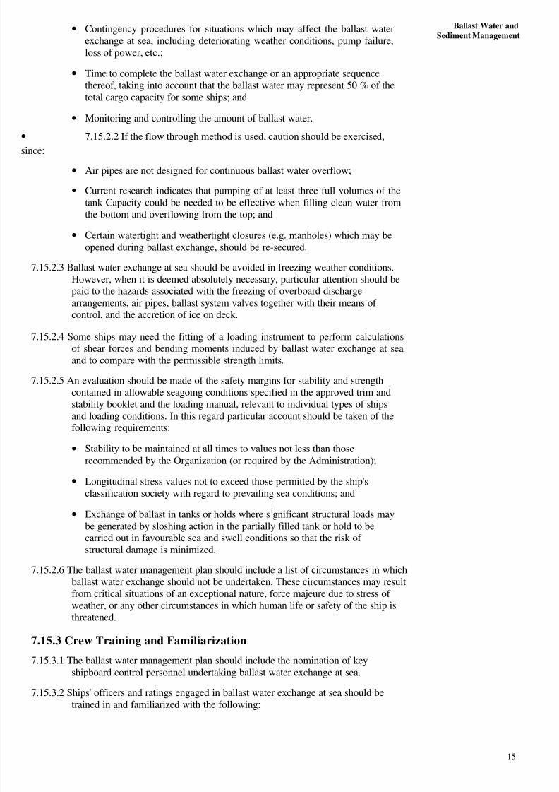
After first being discovered in 1990 along the St. Claire River (a Canadian river north of Detroit), gobles have been found in eastern and southern Lake Erie, southern Lake Huron.southern Lake Michigan, and western Lake Superior. They now have access to America'slargest watershed because the Grand Calumet River (which begins at Lake Michigan nearChicago) connects with the Mississippi River.
Figure 7.4: Photo courtesy of University of Wisconsin Sea Grant, Photographer: D. Jude
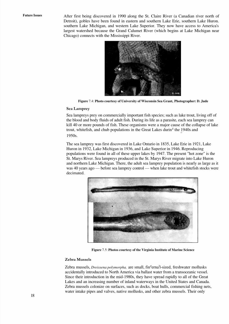
Sea Lamprey
Sea lampreys prey on commercially important fish species; such as lake trout, living off of the blood and body fluids of adult fish. During its life as a parasite, each sea lamprey cankill 40 or more pounds of fish. These organisms were a major cause of the collapse of laketrout, whitefish, and chub populations in the Great Lakes during the 1940s and
t7
1950s.
The sea lamprey was first discovered in Lake Ontario in 1835, Lake Erie in 1921, LakeHuron in 1932, Lake Michigan in 1936, and Lake Superior in 1946. Reproducingpopulations were found in all of these upper lakes by 1947. The present "hot zone" is theSt. Marys River. Sea lampreys produced in the St. Marys River migrate into Lake Huronand northern Lake Michigan. There, the adult sea lamprey population is nearly as large as it
was 40 years ago — before sea lamprey control — when lake trout and whitefish stocks weredecimated.
Figure 7.5: Photos courtesy of the Virginia Institute of Marine Science
Zebra Mussels
Zebra mussels, Dreissena polymorpha, are small, fingernail-sized, freshwater mollusksaccidentally introduced to North America via ballast water from a transoceanic vessel.Since their introduction in the mid-1980s, they have spread rapidly to all of the GreatLakes and an increasing number of inland waterways in the United States and Canada.Zebra mussels colonize on surfaces, such as docks, boat hulls, commercial fishing nets,water intake pipes and valves, native mollusks, and other zebra mussels. Their only
8/6/2019 IMU Future Issues
http://slidepdf.com/reader/full/imu-future-issues 18/123
Ballast Water andSediment Management
known predators, some diving ducks, freshwater drum, carp, and sturgeon, are notnumerous enough to have a significant effect on them. Zebra mussels have greatlyimpacted the Great Lakes ecosystem and economy.
Figure 7.6: Photo courtesy of the Center for Great Lakes and Aquatic Sciences
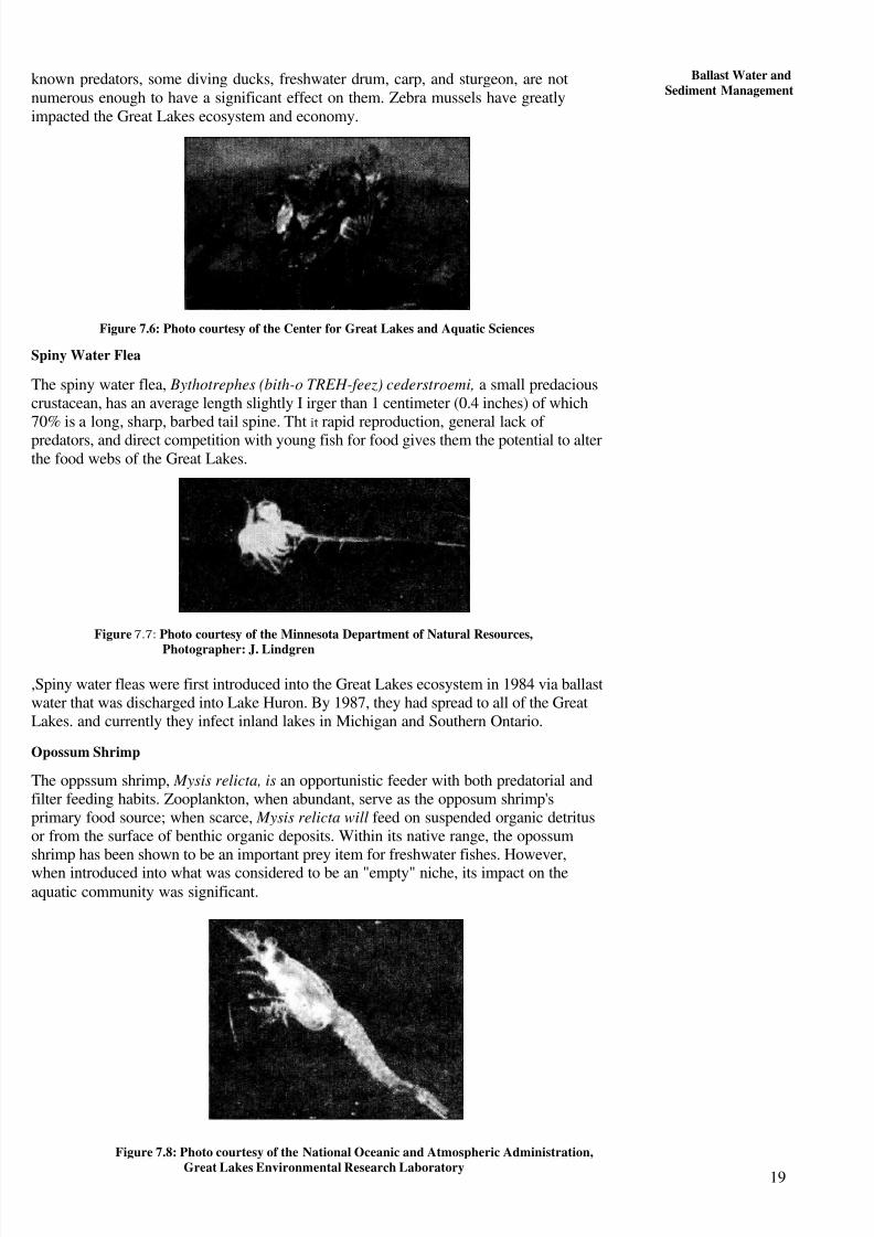
Spiny Water Flea
The spiny water flea, Bythotrephes (bith-o TREH-feez) cederstroemi, a small predaciouscrustacean, has an average length slightly I irger than 1 centimeter (0.4 inches) of which70% is a long, sharp, barbed tail spine. Tht it rapid reproduction, general lack of predators, and direct competition with young fish for food gives them the potential to alterthe food webs of the Great Lakes.
Figure 7.7: Photo courtesy of the Minnesota Department of Natural Resources,
Photographer: J. Lindgren
,Spiny water fleas were first introduced into the Great Lakes ecosystem in 1984 via ballastwater that was discharged into Lake Huron. By 1987, they had spread to all of the GreatLakes. and currently they infect inland lakes in Michigan and Southern Ontario.
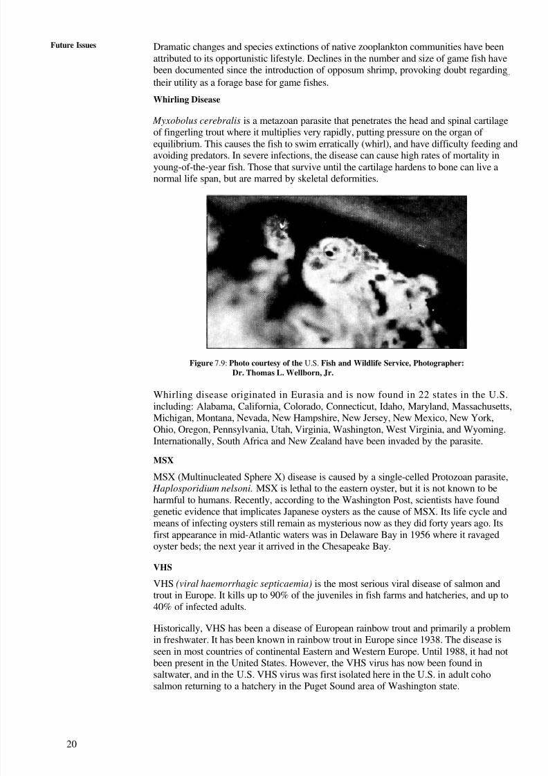
Opossum Shrimp
The oppssum shrimp, Mysis relicta, is an opportunistic feeder with both predatorial andfilter feeding habits. Zooplankton, when abundant, serve as the opposum shrimp'sprimary food source; when scarce, Mysis relicta will feed on suspended organic detritusor from the surface of benthic organic deposits. Within its native range, the opossumshrimp has been shown to be an important prey item for freshwater fishes. However,
when introduced into what was considered to be an "empty" niche, its impact on theaquatic community was significant.
Figure 7.8: Photo courtesy of the National Oceanic and Atmospheric Administration,Great Lakes Environmental Research Laboratory
19
8/6/2019 IMU Future Issues
http://slidepdf.com/reader/full/imu-future-issues 19/123
20
Future Issues Dramatic changes and species extinctions of native zooplankton communities have beenattributed to its opportunistic lifestyle. Declines in the number and size of game fish havebeen documented since the introduction of opposum shrimp, provoking doubt regarding
Z7
their utility as a forage base for game fishes.
Whirling Disease
Myxobolus cerebralis is a metazoan parasite that penetrates the head and spinal cartilage
of fingerling trout where it multiplies very rapidly, putting pressure on the organ of equilibrium. This causes the fish to swim erratically (whirl), and have difficulty feeding andavoiding predators. In severe infections, the disease can cause high rates of mortality inyoung-of-the-year fish. Those that survive until the cartilage hardens to bone can live anormal life span, but are marred by skeletal deformities.
Figure 7.9: Photo courtesy of the U.S. Fish and Wildlife Service, Photographer:Dr. Thomas L. Wellborn, Jr.
Whirling disease originated in Eurasia and is now found in 22 states in the U.S.
including: Alabama, California, Colorado, Connecticut, Idaho, Maryland, Massachusetts,Michigan, Montana, Nevada, New Hampshire, New Jersey, New Mexico, New York,Ohio, Oregon, Pennsylvania, Utah, Virginia, Washington, West Virginia, and Wyoming.Internationally, South Africa and New Zealand have been invaded by the parasite.
MSX
MSX (Multinucleated Sphere X) disease is caused by a single-celled Protozoan parasite, Haplosporidium nelsoni. MSX is lethal to the eastern oyster, but it is not known to beharmful to humans. Recently, according to the Washington Post, scientists have foundgenetic evidence that implicates Japanese oysters as the cause of MSX. Its life cycle andmeans of infecting oysters still remain as mysterious now as they did forty years ago. Itsfirst appearance in mid-Atlantic waters was in Delaware Bay in 1956 where it ravaged
oyster beds; the next year it arrived in the Chesapeake Bay.
VHS
VHS (viral haemorrhagic septicaemia) is the most serious viral disease of salmon andtrout in Europe. It kills up to 90% of the juveniles in fish farms and hatcheries, and up to40% of infected adults.
Historically, VHS has been a disease of European rainbow trout and primarily a problemin freshwater. It has been known in rainbow trout in Europe since 1938. The disease isseen in most countries of continental Eastern and Western Europe. Until 1988, it had notbeen present in the United States. However, the VHS virus has now been found insaltwater, and in the U.S. VHS virus was first isolated here in the U.S. in adult cohosalmon returning to a hatchery in the Puget Sound area of Washington state.

8/6/2019 IMU Future Issues
http://slidepdf.com/reader/full/imu-future-issues 20/123
21
4 Ballast Water andSediment Management
Figure 7.10
Purple Loosestrife
Purple loosestrife (Lythrum salicaria) grows so densely that it crowds out, kills, andreplaces native plants. This is particularly devastating because purple loosestrife replacesplants that animals depend on for food and shelter; and, it has no food and little sheltervalue. Muskrats are dying out in some areas because their diet of cattails has beenseverely reduced by purple loosestrife. Infestations can become so bad, that they block
water flow. Purple loosestrife can reduce biodiversity rates from 900 to 1 species. Thisinvasive plant can produce up to 2.7 million seeds per plant yearly, and spreads acrossapproximately 1 million additional acres of wetlands each year.
Purple loosestrife is a perennial plant native to Europe. It was brought to North America inthe early 1800s by immigrants who valued its striking purple flowers. Seeds were alsounintentionally transported to the shores of North America in the ballast water of ships.Since then, purple loosestrife has expanded its range; now, it is a serious pest of wetlandsand pastures.
Figure 7.11: Photo courtesy of the U.S. Environmental Protection Agency,Photographer: Karen Holland
SAQ 1
(a) What prompted the need to address Ballast Water Management as animportant environmental hazard?
(b) What IMO Resolution governs Ballast Water Management and what are the
objectives of the resolution?
(c) What is a Ballast Water Management Plan and what must it contain?

8/6/2019 IMU Future Issues
http://slidepdf.com/reader/full/imu-future-issues 21/123
22
Future Issues (d) What records are required to be maintained wrt Ballast water on board?
(e) Briefly describe the precautions a vessel must take to minimizeenvironmental pollution by way of efficient ballast water management.
(f) What are the various options vessels have w.r.t ballast water management?
(g) How can port states monitor/enforce ballast water management practices?
(h) What are the means of carrying out ballast water exchange on board?Discuss the pros and cons of the exchange methods.
(i) What safety precautions must a vessel take during ballast water exchange?
What must the crew be trained and familiarized in w.r.t. ballast watermanagement?
7.17 SUMMARY
In this unit we have learnt the reasons as to why ballast water is considered as an importantenvironmental hazard and the importance of the need for every ship to minimize thetransfer of harmful aquatic organisms and pathogens which though are contained in theballast water management plan which is ship-specific provides safe and effectiveprocedures for ballast water management, but at the same time, ballast water exchangeprocedures contained in the plans should be individually assessed for their effectivenessfrom the environmental point of view and the dangers that they may present to a ship'sstructural strength and stability.
Note: Some of the pictures/images used in this Unit have been sourced from the internet.
We wish to thank the creators/publishers for the usage of their material.

8/6/2019 IMU Future Issues
http://slidepdf.com/reader/full/imu-future-issues 22/123
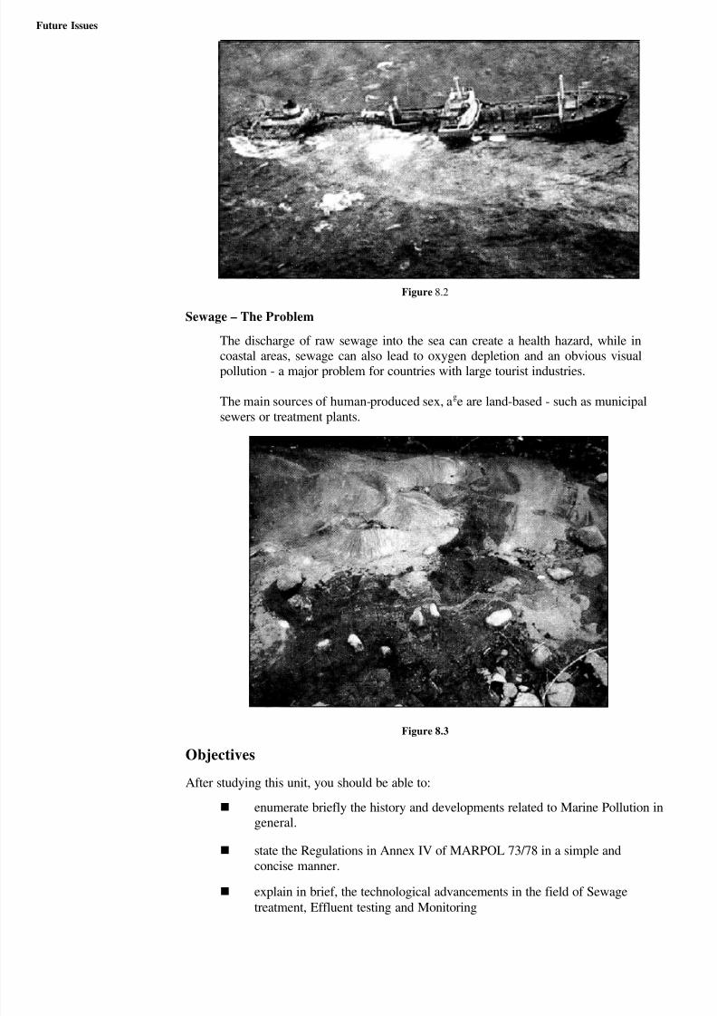
Figure 8.1
Initially the major concern was directed towards ship-generated pollution by Mineral Oil,Chemicals and Dangerous cargo carried in packages. But, in the recent years emphasiswas also given to the other types of pollutants such as Sewage, Garbage and Smoke andPaints on the ships hull. '13
UNIT 8 MARPOL ANNEXURE IV
Structure
8.1 Introduction
Objectives
8.2 Marpol 73/78, A Brief History
8.3 Annex IV — Regulations for The Prevention of Pollution by Sewage fromShips
8.4 Form of Certificate
8.5 Calculations on Sewage Generation
8.6 The Factors on which the Quality of Effluent is Based
8.7 Effluent Quality Standards
8.8 Typical Sewage Treatment Plants
8.9 Summary
8.1 INTRODUCTION
In the olden times there was no control on the indiscriminate dumping of various types of pollutants and effluents from the Ships at sea. Due to technological advancements andconsequent innovations in the marine industry the number of ships sailing at seaincreased significantly and the need to curb various types of marine pollution and tosafeguard the ocean and coastline was felt by various countries. Consequently a number of seagoing nations joined together and decided to keep a control on the polluting effluentsdischarged from the ships. The Marine pollutants could be broadly classified in to two
categories. They are
(1) Operational wastes which is produced during the day to day running of the shipsand discharged overboard either treated or untreated and
(ii) Accidental pollution which is caused due to unforeseen or inadvertent incidents onboard ships.
8/6/2019 IMU Future Issues
http://slidepdf.com/reader/full/imu-future-issues 23/123
Future Issues
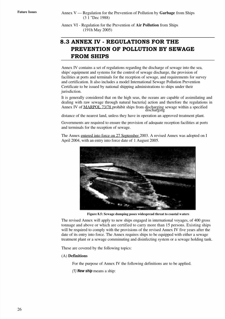
Figure 8.2
Sewage – The Problem
The discharge of raw sewage into the sea can create a health hazard, while in
coastal areas, sewage can also lead to oxygen depletion and an obvious visualpollution - a major problem for countries with large tourist industries.
The main sources of human-produced sex, age are land-based - such as municipalsewers or treatment plants.
Figure 8.3
Objectives
After studying this unit, you should be able to:
enumerate briefly the history and developments related to Marine Pollution ingeneral.
state the Regulations in Annex IV of MARPOL 73/78 in a simple andconcise manner.
explain in brief, the technological advancements in the field of Sewagetreatment, Effluent testing and Monitoring

8/6/2019 IMU Future Issues
http://slidepdf.com/reader/full/imu-future-issues 24/123
Being conscious of the need to preserve the Marine Environment and to keep the oceanspollution free a multilateral instrument was concluded namely the "InternationalConvention for the Prevention of Pollution of the Sea by Oil" way back in 1954.Though this convention had contributed significantly towards the protection of coastalareas it's effectiveness on preserving the wider areas of ocean was minimum.
Ina constant effort to achieve complete elimination of Intentional pollution and to
minimize accidental discharges of harmful substances from ships the InternationalConvention for the Prevention of Pollution from Ships, 1973, was adopted by theInternational Conference on Marine Pollution convened by International MaritimeOrganization (IMO) in November 1973.
The above convention was subsequently modified by the Protocol of 1978, which wasadopted by the International Conference on Tanker Safety and Pollution prevention(TSPP) convened by IMO in February 19 78. This convention, as modified by the 1978Protocol, is known as the "International Convention for the Prevention of Pollutionfrom Ships, 1973, as modified by the Protocol of 1978" or "MARPOL 73/78".
Figure 8.4
A body called The Marine Environment Protection Committee (MEPC) was formed in1974 to review and to give clarifications on provisions, which were found to beambiguous in nature or have given rise to difficulties in implementation. MEPC alsoprovided uniform interpretations, amended the existing regulations and introduced new
regulations with the aim of further reducing operational and accidental pollution from ships.
The regulations covering the various sources of ship-generated pollution was contained inthe Six Annexes of the Convention. They are listed below with their date of entry in to forcegiven in brackets:
Annex I — Regulation for the Prevention of Pollution by Oil (02nd Oct 1983)
Annex 11— Regulation for the Control of Pollution by
Noxious Liquid Substances in Bulk (06th Apr 1987)
Annex III - Regulation for the Prevention of Pollution by Harmful Substances Carried bySea in Packaged Form (01" Jul '92)
Annex IV — Regulation for the Prevention of Pollution by Sewage from Ships (27th Sep2003)
25
8/6/2019 IMU Future Issues
http://slidepdf.com/reader/full/imu-future-issues 25/123
26
Future Issues Annex V — Regulation for the Prevention of Pollution by Garbage from Ships(3 1 "Dec 1988)
Annex VI - Regulation for the Prevention of Air Pollution from Ships(191h May 2005)
8.3 ANNEX IV - REGULATIONS FOR THE
PREVENTION OF POLLUTION BY SEWAGE
FROM SHIPS
Annex IV contains a set of regulations regarding the discharge of sewage into the sea,ships' equipment and systems for the control of sewage discharge, the provision of facilities at ports and terminals for the reception of sewage, and requirements for surveyand certification. It also includes a model International Sewage Pollution PreventionCertificate to be issued by national shipping administrations to ships under their jurisdiction.
It is generally considered that on the high seas, the oceans are capable of assimilating anddealing with raw sewage through natural bacteria] action and therefore the regulations inAnnex IV of MARPOL 73/78 prohibit ships from discharging sewage within a specified
dischargingdistance of the nearest land, unless they have in operation an approved treatment plant.
Governments are required to ensure the provision of adequate reception facilities at portsand terminals for the reception of sewage.
The Annex entered into force on 27 September 2003. A revised Annex was adopted on IApril 2004, with an entry into force date of 1 August 2005.
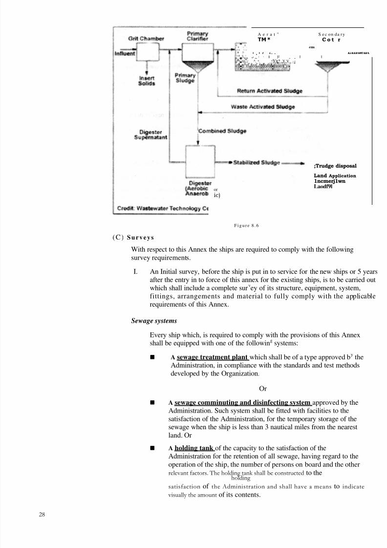
Figure 8.5: Sewage dumping poses widespread threat to coastal waters
The revised Annex will apply to new ships engaged in international voyages, of 400 gross
tonnage and above or which are certified to carry more than 15 persons. Existing shipswill be required to comply with the provisions of the revised Annex IV five years after thedate of its entry into force. The Annex requires ships to be equipped with either a sewagetreatment plant or a sewage comminuting and disinfecting system or a sewage holding tank.
These are covered by the following topics:
(A) Definitions
For the purpose of Annex IV the following definitions are to be applied.
(1) New ship means a ship:

8/6/2019 IMU Future Issues
http://slidepdf.com/reader/full/imu-future-issues 26/123
27
Marpol Annexure IV(a) for which the building contract is placed, or the keel of which islaid, or which is at similar stage of construction, on or after the date of entry into force (27th Sep 2003).
or
(b) the delivery of which is three years or more after the date of entry intoforce (27th Sep 2003)
(2) Existing ship means a ship which is not a new ship.
(3) Sewage means:
(a) drainage and other wastes from any form of toilets and urinals;
(b) drainage from medical premises (dispensary, sick bay, etc.) via washbasin, wash tubs and scuppers located in such premises;
(c) drainage from spaces containing living animals; or
(d) other waste water when mixed with the drainages defined above.
(4) Holding tank means a tank used for the collection and storage of sewage.
(5) Nearest land. The term "from the nearest land" means from the baselinefrom which the territorial sea of the territory in question is established inaccordance with international law.
Note: For the purpose of the present Convention there is a deviation for thisrule in respect of the north-eastern coast of Australia which is indicated inlatitudes and longitudes. Please refer to the original version of MARPOL73/78 for details)
(6) International voyage means a voyage from a country to which the presentConvention applies to a port outside such country, or conversely.
(7) Person means member of the crew and passengers.
(8) Anniversary date means the day and the month of each year which willcorrespond to the date of expiry of the International Sewage PollutionPrevention Certificate.
(B) Application
The effective implementation date of this Annex was 27th September 2003.
A revised annex was adopted on I" April 2004 and entered into force on l"August 2005
The revised Annex applies to new ships engaged in international voyages, of
400 gross tonnage and above and ships of less than 400 gross tors which arecertified to carry more than 15 persons.
All Existing ships will be required to comply with the provisions of the revisedAnnex IV five years after the date of its entry into force.
The Annex requires ships to be equipped with either a.
Sewage Treatment Plant Or
Sewage Comminuting And Disinfecting System Or
Sewage Holding Tank.
8/6/2019 IMU Future Issues
http://slidepdf.com/reader/full/imu-future-issues 27/123
28
A e r a t " S e c on da r y
TM* C o t r
41MA
. - -*' ~ ' ' - -
^. * . * Ylt* ,Y.V
;Trudge disposal
Land Application
1ncmerj1wnLaodf9l
or
ic)
F i g u r e 8 . 6
(C) Surveys
With respect to this Annex the ships are required to comply with the followingsurvey requirements.
I. An Initial survey, before the ship is put in to service for the new ships or 5 yearsafter the entry in to force of this annex for the existing ships, is to be carried out
which shall include a complete surv
ey of its structure, equipment, system,fittings, arrangements and material to fully comply with the applicablerequirements of this Annex.
Sewage systems
Every ship which, is required to comply with the provisions of this Annexshall be equipped with one of the following systems:
A sewage treatment plant which shall be of a type approved by theAdministration, in compliance with the standards and test methodsdeveloped by the Organization.
Or
A sewage comminuting and disinfecting system approved by theAdministration. Such system shall be fitted with facilities to thesatisfaction of the Administration, for the temporary storage of thesewage when the ship is less than 3 nautical miles from the nearestland. Or
A holding tank of the capacity to the satisfaction of theAdministration for the retention of all sewage, having regard to theoperation of the ship, the number of persons on board and the otherrelevant factors. The holding tank shall be constructed to the
holding satisfaction of the Administration and shall have a means to indicate
visually the amount of its contents.
8/6/2019 IMU Future Issues
http://slidepdf.com/reader/full/imu-future-issues 28/123
Marpol Annexure IV The ship should be equipped with a pipeline leading to the
exterior for discharge to a reception facility. This pipe has to befitted with a standard shore connection as described later on.
2 A renewal survey at intervals not exceeding five years is to be carried out.The nature and requirement of this survey is similar to that for the initialsurvey. Normally the survey is carried out by officers of the Administration(Flag State). However, this job can be entrusted to the nominated Surveyorsor to the Organizations recognized by the Administration.
3' An additional survey is carried out if any modification or changes in thestructure, equipment, system, fittings, arrangement or material is made dueto any reason such as accidents or defect rectification. This survey is to makesure that the repair or renewal is effectively made, that the material and theworkmanship is satisfactory in all respect and comply with the requirementsof this annex.
4 The survey of the ship will be carried out to enforce this Annex. However, atany time, if this nominated surveyor or Organization feels that the shippresents a reasonable threat of harm to the marine environment he should takeappropriate corrective action. Or the certificate shall be withdrawn and thesefacts should be notified to the Administration. Also, the Port State authority
shall be notified if the ship is in a different country. in such case theGovernment of the Port State shall assist the surveyor to carry out theirobligations under this regulation or take such step to ensure that the ship shallnot sail until the defects are rectified.
5. After any survey of a ship is completed, no change shall be made in thestructure, equipment, systems, fittings, arrangements or the material coveredby the survey with out the sanction of the Administration, except the directreplacement of such equipment and fittings. Whenever any accident takesplace or a defect is discovered to the system-or equipment which maysubstantially affect the integrity of the ship or the efficiency or the
completeness of its equipment covered by this annex, the Master or theOwner of the ship shall report at the earliest to the Administration, and thenominated Surveying authority. A report is also made to the Port State if thevessel is in a different country. On investigation, if found necessary thenominated surveying authority shall conduct a resurvey and steps forcorrective action shall be taken accordingly.
Figure 8.729
8/6/2019 IMU Future Issues
http://slidepdf.com/reader/full/imu-future-issues 29/123
Future Issues (D) Issue or Endorsement of Certificate
An International Sewage Pollution Prevention Certificate shall be issued, after aninitial survey or renewal survey as described earlier to any ship which is engaged invoyages or offshore terminals. In the case of existing ships this requirement shallapply five years after the date of entry in to force of this annex.
Such Certificate shall be issued or endorsed either by the Administration or by anyperson or organization duly authorized by it. In every case, the Administrationassumes full responsibility for the Certificate.
(E) Issue or Endorsement of a Certificate by another Government
(1) The Government of a party to the convention may, at the request of theAdministration, cause a ship to be surveyed and, if found satisfactory thatthe provisions of this Annex are complied with, shall issue or authorize theissue of an International Sewage Pollution Prevention Certificate to the ship,and where appropriate, endorse or authorize the endorsement of that Certificateon the ship in accordance with this Annex.
(2) A copy of the Certificate and a copy of the survey report shall be transmittedas soon as possible to the Administration requesting the survey.
(3) A Certificate so issued shall contain a statement to the effect that it has beenissued at the request of the Administration and shall have the same force andreceive the same recognition as the Certificate issued under this annex.
(4) No International Sewage Pollution Prevention Certificate shall be issued to aship which is entitled to fly the flag of a State which is not a party.
8.4 FORM OF CERTIFICATE
The International Sewage Pollution Prevention Certificate shall be drawn upcorresponding to the form given in Marpol Annex IV. If the language used is notEnglish, French or Spanish, the text shall include a translation into one of these
Z~
languages. The format of the certificate is given on the next two pages.
(A) Duration and validity of Certificate
1. An International Sewage Pollution Prevention Certificate shall be issued for aperiod specified by the Administration which shall not exceed five years.
2. The renewal survey can be carried out in a window of (+/-) 3 months of theexpiry date of the existing certificate. If the renewal survey is completedduring this range dates, the new Certificate will be valid from the actual dateof completion of the survey to a date not exceeding five years from the date of expiry of the existing certificate. However, if the renewal survey is completedmore than three months before the expiry of the existing certificate, the newcertificate shall be valid from the date of completion of the renewal survey toa date not exceeding five years from the date of completion of the renewalsurvey.
3. If a Certificate is issued fora period of less than five years then theadministration may extend the validity to a maximum of five years.
4. If a new certificate cannot be issued or placed on board when a renewalsurvey has been completed before the expiry date of the existing certificatethen the existing certificate shall be endorsed to extend the validity for amaximum period of five months from the date of expiry.

8/6/2019 IMU Future Issues
http://slidepdf.com/reader/full/imu-future-issues 30/123
31
Marpol Annexure IV
INTERNATIONAL SEWAGE POLLUTION PREVENTION
CERTIFICATE (1973)
Issued under the Provisions of the International Convention for the Prevention of Pollution from Ships, 1973, under the authority of the Government of
(Full designation of the country)
by ........................................................................................................................................
(full designation of the competent person or organization authorized under the provisionsof the International Convention for the Prevention of Pollution from Ships, 1973)
Number of
NameShip
Distinctivenumber or lettes
Port of registry Gross tonnage persons which theship is certified to
carry
New/existing
ship*
Date of building contract .....................................................................................................
Date on which keel was laid or ship
was at a similar stage of construction .................................................................................
Date of delivery ...................................................................................................................
* Delete as appropriate.

8/6/2019 IMU Future Issues
http://slidepdf.com/reader/full/imu-future-issues 31/123
Future Issues
THIS IS TO CERTIFY:
(1) The ship is equipped with a sewage treatment plant/comminutes/ holding tank* and
a discharge pipeline in compliance with regulation .......................... of Annex IV of the Convention as follows:
*(a) Description of the sewage treatment plant:
Type of sewage treatment plant .................................................................................
Name of manufacturer................................................................................................The sewage treatment plant is certified by the Administration to meet the following
effluent standards* .........................................................................
*(b) Description of comminuter:
Type of comminuter...................................................................................................
Name of manufacturer................................................................................................Standard of sewage after disinfection........................................................................
*(c) Description of holding tank equipment:
Total capacity of the holding tank ................................................................................ m3
Location..........................................................................................................
(d) A pipeline for the discharge of sewage to a reception facility. Fitted with a standardshore connection.
(2) The ship has been surveyed in accordance with regulation .... of Annex IV of theInternational Convention for the Prevention of Pollution from Ships, 1973,concerning the prevention of pollution by sewage and the survey showed that theequipment of the ship and the condition thereof are in all respects satisfactory and theship complies with the applicable requirements of Annex IV of the Convention.
This certificate is valid until ......................................................................................
Issued at
(place of issue of certificate)
(Date of issue) Signature of official issuing the certificate
(seal or stamp of the issuing authority, as appropriate)
Under the provisions of regulation of Annex IV of the Convention thevalidity of this certificate is extended until.
Signed
(Signature of duly authorized official)
Place ......................................................................
Date ......................................................................
(Seal or stamp of the authority, as appropriate)
Delete as appropriate.
Parameters should be incorporated.

8/6/2019 IMU Future Issues
http://slidepdf.com/reader/full/imu-future-issues 32/123
33
Marpol Annexure IV5. If a certificate expires when the ship is not in a port, where it can be surveyed,the Administration may extend the validity, for the purpose of completing thepresent voyage, for a maximum period of three months. This extension issolely for the purpose of completing its voyage and she shall not sail out, byvirtue of such extension, from such port with out completing the renewalsurvey.
6. When a ship is on short voyages the validity of certificate may be extendedfor a grace period of one month from the date of expiry. In the two cases
above , when the renewal survey is completed, the new certificate shall bevalid to a date not exceeding five years from the date of expiry of theexisting certificate before the extension was granted.
7. In special circumstances, as determined by the Administration, a newCertificate shall be valid to a date not exceeding five years from the date of completion of renewal survey, instead of the date of expiry of the existingCertificate.
8. The certificates which are extended under the rule stated in the aboveparagraph shall cease to be valid:
paragraph
If the relevant surveys are not completed within the periods specified
in this Annex.
If the flag of the ship is changed.
Note: The new Administration shall issue the Certificate only after satisfyingthat the vessel is in compliance the requirements as laid down in this Annex
9. If the ship transfers flag to another country then the certificate will becomeinvalid, except that the certificate will remain valid fora further period of 5months, till then the new flag state should issue a new certificate and placethat onboard the ship. After the transfer takes place the the ship shouldtransfer to the old flag state the copy of the certificate with a copy of thesurvey report if possible.
(B) Discharge of Sewage
I Subject to the provisions of of this Annex, the discharge of sewage into seais prohibited, except when:
the ship is discharging comminuted and disinfected sewage using asystem approved by the Administration at a distance of more than 3nautical miles from the nearest land, or sewage which is not comminutedor disinfected at distance of more than 12 nautical miles from the nearestland, provided that, in any case, the sewage that has been stored in holdingtanks shall not be discharged
Figure 8.8
8/6/2019 IMU Future Issues
http://slidepdf.com/reader/full/imu-future-issues 33/123
3433
• instantaneously but at moderate rate when the ship is en route and proceeding atnot less than 4 knots: the rate of discharge shall be approved by the
C~
Administration based upon standards developed by the Organization:
• the ship has in operation an approved sewage plant which has beencertified by the Administration to Meet the operational requirements referred to inthis annex, And
the test results of the plant are laid down in the ship's internationalSewage Pollution Prevention Certificate, And
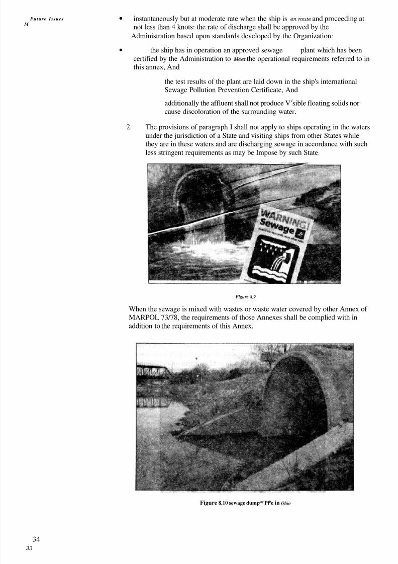
additionally the affluent shall not produce Visible floating solids norcause discoloration of the surrounding water.
2. The provisions of paragraph I shall not apply to ships operating in the watersunder the jurisdiction of a State and visiting ships from other States whilethey are in these waters and are discharging sewage in accordance with suchless stringent requirements as may be Impose by such State.
Figure 8.9
When the sewage is mixed with wastes or waste water covered by other Annex of MARPOL 73/78, the requirements of those Annexes shall be complied with inaddition to the requirements of this Annex.
Figure 8.10 sewage dumping Pipe in Ohio
Future I s sues
M

8/6/2019 IMU Future Issues
http://slidepdf.com/reader/full/imu-future-issues 34/123
35
Marpol Annexure IN'I C) Exceptions
I The regulations concerning the discharge of sewage do not apply to:
the discharge of sewage from a ship necessary for the purpose of securing the safety of a ship and those on board orsaving life at sea or
the discharge of sewage resulting from damage to a ship or its
equipment if all reasonable precautions have been taken before andafter the occurrence of the damage, for the purpose of preventing orminimizing the discharge.
Figure 8.11: Sewage dump area near a coast
(D) Reception facilities
The government of each Party to the convention, which requires ships operating inwaters under its jurisdiction and visiting ships while in its water undertakes to ensurethe provision of reception facilities at ports and terminals of the reception of sewage,without causing delay to ships, adequate to meet the needs of the ships using them.The Government of each Party shall notify the Organization, for transmission to thecontracting Governments concerned, of all cases where the facilities providedcontractingunder this regulation are alleged to be inadequate.
regulatio
Standard Discharge Connections
To enable pipes of reception facilities to be connected with the ship's dischargepipeline, both lines shall be fitted with a standard discharge connection inaccordance with the following table.
DESCRIPTION DIMENSION
Outside diameter 210 mm
Inner diameter According to pipe diameter
Bolt circle diameter 170 mmSlots in flange 4 holes, 18 mm in diameter, equidistantly placed on
a bolt circle of the above diameter, slotted to theflange periphery. The slot width to be 18 mm
Flange thickness 16 mm
Bolts and nuts (quantity and'dia) 4, each of 16 mm in diameter and of suitable lengthThe flange is designed to accept pipes up to a maximum internal diameter of 100 mm and
designe
be of steel or other equivalent material having a flat face. This flange, together witha suitable gasket, shall he suitable for a service pressure of 6 kg/cm2.
For ships g havin a moulded depth of 5 m and less, the inner diameter of theI
discharge connection may be 38 mm.

8/6/2019 IMU Future Issues
http://slidepdf.com/reader/full/imu-future-issues 35/123
36
Future Issues
8.5 CALCULATIONS ON SEWAGE GENERATION
The exact amount of sewage and waste water flow generated on board is difficult toquantify, However, the following guidelines are sometimes used.
Sonic of the European designers tend to work on the basis of 70 litres percap per day (lpcd) of toilet waste including flushing water and about 130-150 1pcd of wash water including that from wash basins, laundry etc.
2. The US authorities suggest that the effluents from toilets may be as high asL_
1 14 Ipcd and wash water twice that quantity.
In order to reduce the quantity of effluents produced in the toilets, thedesigners have come out with various innovations such as:
(i) Recycling of flushing water.
(ii) Vacuum system in which the solid waste is sucked using negligibleamount of flushing water
The effluents produced in showers, baths and wash basins arenormally discharged overboard directly. However, local regulations incertain countries do not permit this.
8.6 THE FACTORS ON WHICH THE QUALITY OFEFFLUENT IS BASED
While discharging treated effluents in territorial waters one or more of thefollowing factors are considered to determine the quality of the said effluents.
I. Biochemical Oxygen Demand (BOD): is a measure of the total amount of oxygen~ 1 —
which will be taken up by the chemical and organic matter in the effluent. It isimportant in two fold. Firstly, if the waterway in which the effluent isis
C,
overloaded with oxygen absorbing matter then the oxygen content in the effectedwater will be reduced to a level at which fish, plants and other living organism willnot be supported. Secondly, a class of bacteria which can live without oxygen willpredominate in the sewage or in the waterway to which it is discharged. Thebacteria associated with this condition produce hydrogen sulfide which is toxic. HODis usually associated with a specific period and that normally taken is five days. Thisvalue, written as BOD5 is determined by incubating one liter sample of sewage at 20"C diluted in well oxygenated water. The amount of oxygen absorbed over the fiveday period is then measured.
2. Suspended solid contents: is unsightly and over a period of time can give rise tosilting problems. They are usually a sign of a malfunctioning sewage plant and whenvery high, will be accompanied by a high BOD. Suspended solids are measured byfiltering a sample through a pre-weighed filter pad which is dried and then re-weighed.
3. The E-coliform: is a family of bacteria which live in human intestine. They can bequantified easily in a laboratory test, the result of which is indicative of the humanwaste present in a particular sewage sample. The result of this test is called a-coll.count and is expressed per 100 ml.

8/6/2019 IMU Future Issues
http://slidepdf.com/reader/full/imu-future-issues 36/123
37
Depending up on the quality of effluents produced the various Administrationshave recognized several types of sewage plants which are collectively described asMarine Sanitation Devices (MSD). The US Coast Guard recognizes the followingdistinctive types:
Type I: A flow-through device from which the effluent contains no visiblefloating solids and produces an e-coli count of less than 1000/100 ml.
Type II: A flow-through device from which the effluent contains suspended solidsof no more than 150 mg/Itr and has an e-coli count of less than 200/100ml.
Type III: A zero discharge device i.e. holding tank or recirculation device.
8.8 TYPICAL SEWAGE TREATMENT PLANTS
Sewage treatment plants are of the following types
Biological sewage treatment plant.Chemical sewage plant
Biological sewage treatment plan(.
Fig — 8.12 is a Diagrammatic view and Fig – 8.13 i s a sectional view of aBiological sewage treatment plant. This type is widely seen on board merchantvessels. This is an aerobic type sewage treatment plant which works on extendedaeration process. Basically this consists of oxygenating the effluent either bybubbling air through it (in this case) or by agitating the surface. By doing so thefamily of bacteria is propagated which thrives on the oxygen content and digeststhe sewage to produce an innocuous sludge. These bacteria reduce the BOD by
converting the organic content of the sewage to a chemically and organically inertsludge.
Y M T E - E A
- e l
*PPATION SETTLING AERATION CHLOR iNPCONTACT
Figure 8.12: Schematic Diagram of Super Trident Sewage Treatment Unit
In order to exist, the bacteria need air and nutrient (the sewage). If the source of nutrient is cut off of by shutting down the plant or by by-passing the treatment plant,the bacteria die and the plant cannot function correctly unless a new colony of
bacteria is generated. This process can take seven to fourteen days. This is also truewhen the plant is commissioned initially or after major repairs. Bacteria which livein the presence of oxygen are called aerobic. When oxygen is not present the
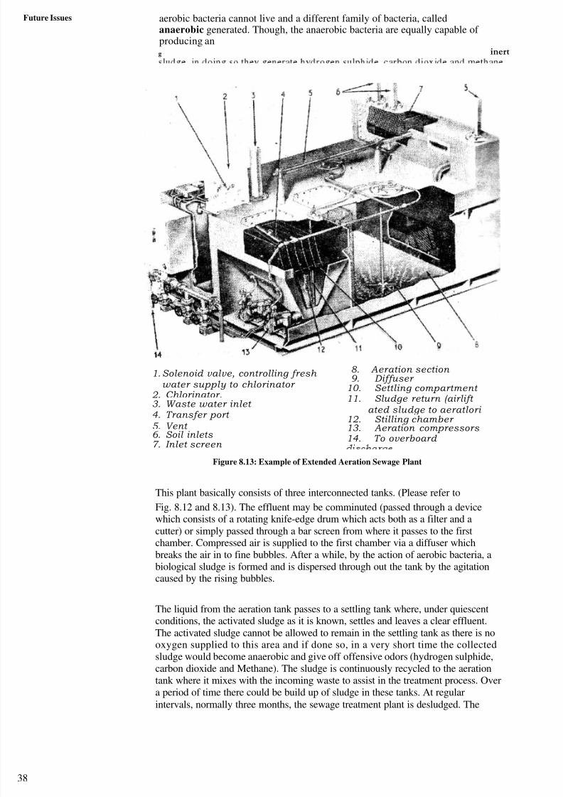
8/6/2019 IMU Future Issues
http://slidepdf.com/reader/full/imu-future-issues 37/123
38
Future Issues aerobic bacteria cannot live and a different family of bacteria, calledanaerobic generated. Though, the anaerobic bacteria are equally capable of producing ang inert
1. Solenoid valve, controlling fresh water supply to chlorinator
2. Chlorinator.3. Waste water inlet
4. Transfer port 5. Vent 6. Soil inlets 7. Inlet screen
8. Aeration section 9. Diffuser
10. Settling compartment 11. Sludge return (airlift
ated sludge to aeratlori
12. Stilling chamber 13. Aeration compressors 14. To overboard
Figure 8.13: Example of Extended Aeration Sewage Plant
This plant basically consists of three interconnected tanks. (Please refer to
Fig. 8.12 and 8.13). The effluent may be comminuted (passed through a devicewhich consists of a rotating knife-edge drum which acts both as a filter and acutter) or simply passed through a bar screen from where it passes to the firstchamber. Compressed air is supplied to the first chamber via a diffuser which
breaks the air in to fine bubbles. After a while, by the action of aerobic bacteria, abiological sludge is formed and is dispersed through out the tank by the agitationcaused by the rising bubbles.
The liquid from the aeration tank passes to a settling tank where, under quiescentconditions, the activated sludge as it is known, settles and leaves a clear effluent.The activated sludge cannot be allowed to remain in the settling tank as there is nooxygen supplied to this area and if done so, in a very short time the collectedsludge would become anaerobic and give off offensive odors (hydrogen sulphide,carbon dioxide and Methane). The sludge is continuously recycled to the aerationtank where it mixes with the incoming waste to assist in the treatment process. Overa period of time there could be build up of sludge in these tanks. At regularintervals, normally three months, the sewage treatment plant is desludged. The

8/6/2019 IMU Future Issues
http://slidepdf.com/reader/full/imu-future-issues 38/123
39
desludging operation entails pumping out about three quarter of the aeration tank contents and refilling with clean water.
The clear effluent is disinfected in the chlorinator in order to reduce the coliforms toan acceptable level. Calcium or sodium hypochlorite solution or tablets are used forchlorination. In some plants disinfection is carried out by ultra violet radiation. Afterchlorination the effluents are passed to the collection tank and held there at
least for 60 minutes for completing the disinfection process. Normally the effluentdischarge pump is operated automatically by the action of level switches
Chemical sewage treatment plant
Fig – 3 shows a diagrammatic representation of Chemical treatment type sewagetreatment plant. It is important to maintain the correct chemical dosage rates andthese are determined by taking daily sample and performing a simple chemical test.Failure to maintain the correct dosage may result in some chemical odour of the flushwater and darkening of its colour. By incorrect dosing the effluent can also develophigh alkalinity and consequent corrosion of the system piping and tanks.
Marpol Annexure IV
SALT WATELR--- ~. 1
STORAGE TANK TO OTHER SERVICES
OVERBOARD
DISCHARGE
"'TO SULLAGE
TANK
CHEMICALTREATMENT
TANK
SETTLIN
G
TANK
Figure 8.14: Example of Chemical Sewage Plant
SAQ 1
(a) Define "Sewage" with respect to MARPOL 73/78 Annex IV.
(b) To which all categories of ships MARPOL 73/78 Annex IV is applicable.
(c) Which all systems are present on ships for dealing with sewage?
(d) What are the various discharge criteria for sewage using various methods?
(e) What is a Standard discharge connection? What are its dimensions?
(f) What are the exceptions under which the discharge criteria are notapplicable'?
YPASS
IN
COMMINUTOR
COMPRESSED AIRSUPPLY
SEA- SUCTION i. 1 L~
FILTER
PRESSURE
T A N K
CHEMICAL
DISSOLVING BASKET,N CHEMICAL
DOSING TANK
RECIRCULATING
PUMP
It*-
TO SULLAGE
t TANK SUCTION
WATER CLOSETS'-
LI

8/6/2019 IMU Future Issues
http://slidepdf.com/reader/full/imu-future-issues 39/123
Future issues (g) What are the special requirements for discharge of sewage using holdingtanks?
(h) Briefly describe how does the Biological sewage treatment plant work?
(i) Briefly describe how does the Chemical sewage treatment plant work?
0) What are Sewage reception facilities? Why are they required in Ports?
8 . 9 SUM M AR Y
Operational wastes which produced during the day to day running of the Ships anddischarge of raw sewage into the sea can create a health hazard while in coastal areas.
We have learnt that every ship which is required to comply with the provisions of this annexis required to be equipped with either a sewage treatment plant, or a sewage comminuting
and disinfecting system or a holding tank, depending on the operation of the ship andnumber of persons on board. We have also learnt in this unit about the mandatorycertificates which are required for ships and about the reception facilities in Pons.
Note: Some of the pictures/images used in this Unit have been sourced from the internet.
We wish to thank the creators/publishers for the usage of their material.
40

8/6/2019 IMU Future Issues
http://slidepdf.com/reader/full/imu-future-issues 40/123
UNIT 9 MARPOL ANNEXURE VI - PART A:
PREVENTION OF AIR POLLUTION
Structure
9.1 Introduction
Objectives
.W 9.2 History of Air Pollution Legislations9.3 IMO's Work on Air Pollution
9.4 Factors Affecting Air Pollution
9.5 Annex VI — Regulations for the Prevention of Air Pol I ution
9.6 Summary
9.1 INTRODUCTION
Air pollution is a broad term applied to any chemical, physical (e.g. particulate matter), orbiological agent that modifies the natural characteristics of the atmosphere. The atmosphere
is a complex, dynamic natural system that is essential to support life on planet earth.Stratospheric ozone depletion due to air pollution has long been recognized as a threat tohuman health as well as to the earth's ecosystems.
Worldwide air pollution is responsible for large numbers of deaths and cases of respiratory disease. Enforced air quality standards, like the Clean Air Act in the UnitedStates, have reduced the presence of some pollutants. While major stationary sources areoften identified with air pollution, the greatest source of emissions are actually mobilesources, principally automobiles. There are many available air pollution controltechnologies and urban planning strategies available to reduce air pollution however,worldwide costs of addressing the issue are high. The most immediate method of improvingair quality would be the use of bioethanol fuel, biodiesel, solar energy. and hybrid vehicle
technologies.
Air pollution can be seen on roads, in the vicinity of power stations, and in shippingroutes where the traffic density is high. Public demand for clean air, backed up byinternational protocols, is putting pressure on the shipping industry to improve theemission standards on board merchant vessels.
Figure 9.1
A containership — one of about 20 a day — travels between the coast of Santa BarbaraCounty and the Channel Islands en route to Long Beach/Los Angeles Harbor. Diesel 41
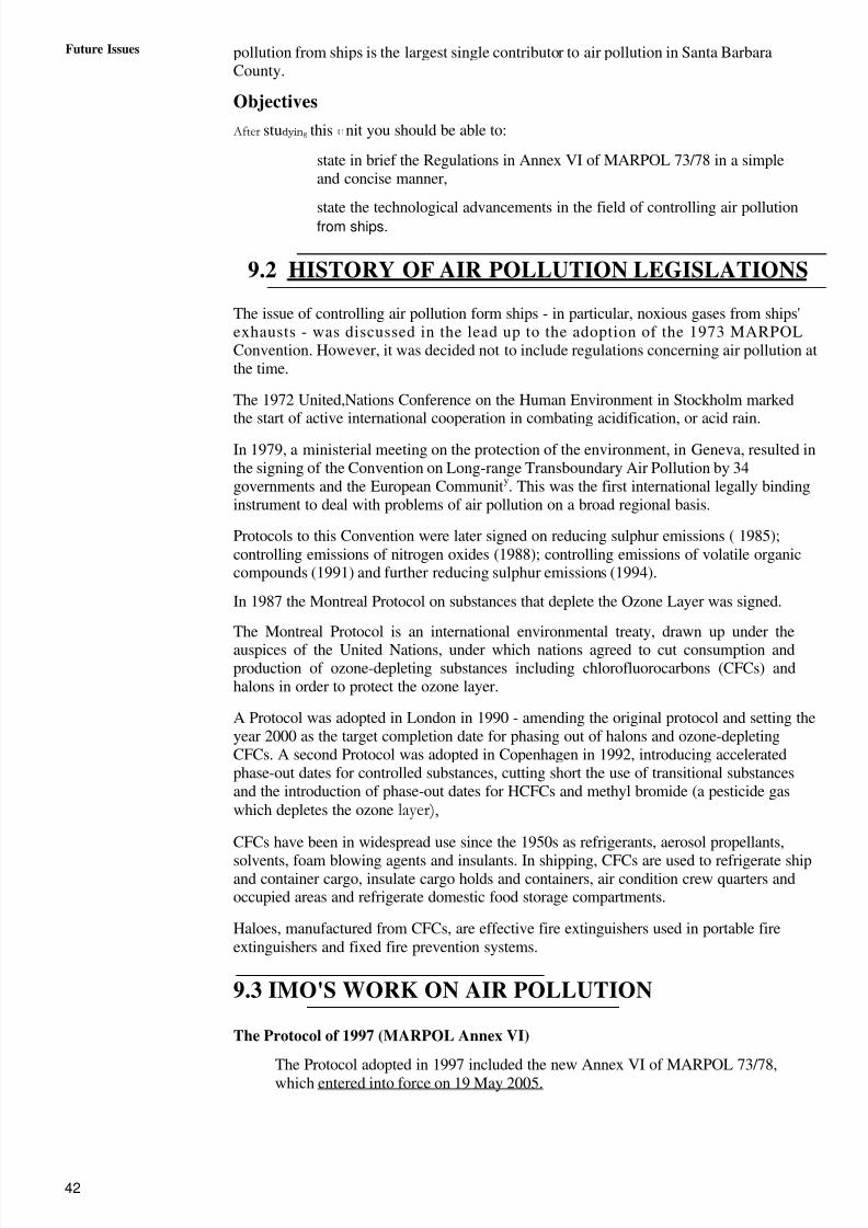
8/6/2019 IMU Future Issues
http://slidepdf.com/reader/full/imu-future-issues 41/123
42
Future Issues pollution from ships is the largest single contributor to air pollution in Santa BarbaraCounty.
Objectives
After studying this U nit you should be able to:
state in brief the Regulations in Annex VI of MARPOL 73/78 in a simpleand concise manner,
state the technological advancements in the field of controlling air pollutionfrom ships.
9.2 HISTORY OF AIR POLLUTION LEGISLATIONS
The issue of controlling air pollution form ships - in particular, noxious gases from ships'exhausts - was discussed in the lead up to the adoption of the 1973 MARPOLConvention. However, it was decided not to include regulations concerning air pollution atthe time.
The 1972 United,Nations Conference on the Human Environment in Stockholm markedthe start of active international cooperation in combating acidification, or acid rain.
In 1979, a ministerial meeting on the protection of the environment, in Geneva, resulted inthe signing of the Convention on Long-range Transboundary Air Pollution by 34governments and the European Community. This was the first international legally bindinginstrument to deal with problems of air pollution on a broad regional basis.
Protocols to this Convention were later signed on reducing sulphur emissions ( 1985);controlling emissions of nitrogen oxides (1988); controlling emissions of volatile organiccompounds (1991) and further reducing sulphur emissions (1994).
In 1987 the Montreal Protocol on substances that deplete the Ozone Layer was signed.
The Montreal Protocol is an international environmental treaty, drawn up under the
auspices of the United Nations, under which nations agreed to cut consumption andproduction of ozone-depleting substances including chlorofluorocarbons (CFCs) andhalons in order to protect the ozone layer.
A Protocol was adopted in London in 1990 - amending the original protocol and setting theyear 2000 as the target completion date for phasing out of halons and ozone-depletingCFCs. A second Protocol was adopted in Copenhagen in 1992, introducing acceleratedphase-out dates for controlled substances, cutting short the use of transitional substancesand the introduction of phase-out dates for HCFCs and methyl bromide (a pesticide gaswhich depletes the ozone layer),
CFCs have been in widespread use since the 1950s as refrigerants, aerosol propellants,
solvents, foam blowing agents and insulants. In shipping, CFCs are used to refrigerate shipand container cargo, insulate cargo holds and containers, air condition crew quarters andoccupied areas and refrigerate domestic food storage compartments.
Haloes, manufactured from CFCs, are effective fire extinguishers used in portable fireextinguishers and fixed fire prevention systems.
9.3 IMO'S WORK ON AIR POLLUTION
The Protocol of 1997 (MARPOL Annex VI)
The Protocol adopted in 1997 included the new Annex VI of MARPOL 73/78,which entered into force on 19 May 2005.

8/6/2019 IMU Future Issues
http://slidepdf.com/reader/full/imu-future-issues 42/123
43
M a r p o l A n n e x u r e I V
Part — A: Prevention
of Air Pollution
MARPOL Annex VI sets limits on sulphur oxide and nitrogen oxide emissionsfrom ship exhausts and prohibits deliberate emissions of zone depletingsubstances.
The annex includes a global cap of 4.5% mom on the sulphur content of fuel oil andcalls on IMO to monitor the worldwide average sulphur content of fuel.
F i g u r e 9 . 2
Annex VI contains provisions allowing for special SOx Emission Control Areas(SECAS) to be established with more stringent controls on sulphur emissions. Inthese areas, the sulphur content of fuel oil used onboard ships must not exceed1.5% m/m. Alternatively, ships must fit an exhaust gas cleaning system or use anyother technological method to limit SOx emissions. The Baltic Sea Area isdesignated as a SOx Emission Control area in the Protocol.
The North Sea was adopted as SOx Emission Control Area in July 2005.
Annex VI prohibits deliberate emissions of ozone depleting substances, which includehalons and chlorofluorocarbons (CFCs). New installations containing ozone-depletingsubstances are prohibited on all ships. But new installations containing hydro-chlorofluorocarbons (HCFCs) are permitted until I January 2020.
Annex VI also sets limits on emissions of nitrogen oxides (NOx) from diesel engines.A mandatory NOx Technical Code, which defines how this shall be done, wasadopted by the Conference under the cover of Resolution 2.
The Annex also prohibits the incineration onboard ship of certain products, such ascontaminated packaging materials and polychlorinated biphenyls (PCBs).
Review of Annex VI
At its 53rd session in July 2005, the MEPC agreed on the need to undertake areview of Annex VI and the NOx Technical Code with a view to revising theregulations to take account of current technology and the need to further reduceemissions from ships. MEPC instructed the Sub-Committee on Bulk Liquids andGases (BLG) to carry out the review by 2007, and specifically to:
examine available and developing techniques for the reduction of emissions of air pollutants; review the relevant technologies and thepotential for a reduction of NOx emissions and recommend futurelimits for NOx emissions.
review technology and the need for a reduction of SOx emissions and justify and recommend future limits for SOx emissions
8/6/2019 IMU Future Issues
http://slidepdf.com/reader/full/imu-future-issues 43/123
Future Issues
44
consider the need, justification and possibility of controlling volatileorganic compounds emissions from cargoes;
with a view to controlling emissions of particulate matter (PM), studycurrent emission levels of PM from marine engines, including theirsize distribution and quantity, and recommend actions to be taken for thereduction of PM from ships. Since reduction of NOx and SO emission isexpected to also reduce PM emission, estimate the level of PM emissionreduction through this route
consider reducing NOx and PM emission limits for existing engines
consider whether Annex VI emission reductions or limitations shouldbe extended to include diesel engines that use alternative fuels andengine systems/power plants other than diesel engines
review the texts of Annex VI, NOx Technical Code and relatedguidelines and recommend necessary amendments.
July 2005 amendments
The Marine Environment Protection Committee (MEPC) at its 53rd session in July2005 adopted amendments to MARPOL Annex VI, including one on the new North
Sea SOx Emission Control Area (SECA). The entry into force date for the North SeaSECA amendment is expected to be 22 November 2006, with its full implementation12 months later.
The Committee noted information gained from monitoring the worldwide sulphurcontent in fuel oils for 2004 which gave a three-year (2002-2004) rolling average of sulphur content in fuel oil worldwide of 2.67% m/m.
The MEPC adopted Guidelines on on-board exhaust gas-SOx cleaning systems;
Survey Guidelines under the Harmonized System for Surve y and Certification for
MARPOL Annex Vk Unified interpretations of MARPOL Annex VI; an dGuidelines for Port State Control under MARPOL Annex VI.
The MEPC also adopted amendments to update the NOx Technical Code.
The MEPC approved Interim Guidelines for Voluntary Ship CO2 Emission'Indexing for Use in Trials.
MEPC 54 outcome
At its 54th session in March 2006, a working groDp was established to considerissues relating to the prevention of air pollution from ships, including follow-upaction to the IMO Policies and practices related to the reduction of greenhouse
.gas emissions from ships (resolution A.963(23)).
Figure 9.3
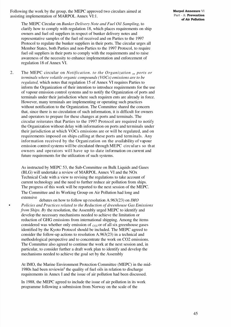
8/6/2019 IMU Future Issues
http://slidepdf.com/reader/full/imu-future-issues 44/123
45
Marpol Annexure VI
Part - A: Prevention
of Air Pollution
Following the work by the group, the MEPC approved two circulars aimed atassisting implementation of MARPOL Annex VI:1.
The MEPC Circular on Bunker Delivery Note and Fuel Oil Sampling, toclarify how to comply with regulation 18, which places requirements on shipowners and fuel oil suppliers in respect of bunker delivery notes andrepresentative samples of the fuel oil received and on Parties to the 1997Protocol to regulate the bunker suppliers in their ports. The circular urges allMember States, both Parties and non-Parties to the 1997 Protocol, to requirefuel oil suppliers in their ports to comply with the requirements and to raise
awareness of the necessity to enhance implementation and enforcement of regulation 18 of Annex VI.
2. The MEPC circular on Notification. to the Organization on ports or
terminals where volatile organic compounds (VOCs) emissions are to be
regulated, which notes that regulation 15 of Annex VI requires Parties toinform the Organization of their intention to introduce requirements for the useof vapour emission control systems and to notify the Organization of ports andterminals under their jurisdiction where such requiren ents are already in force.However, many terminals are implementing or operating such practiceswithout notification to the Organization. The Committee shared the concernthat, since there is no circulation of such information, it is difficult for ownersand operators to prepare for these changes at ports and terminals. Thecircular reiterates that Parties to the 1997 Protocol are required to notifythe Organization without delay with information on ports and terminals undertheir jurisdiction at which VOCs emissions are or will be regulated, and onrequirements imposed on ships calling at these ports and terminals. Anyinformation received by the Organization on the availability of vapouremission control systems will be circulated through MEPC circular s so thatowners and operators wil l have up to-date information on current andfuture requirements for the utilization of such systems.
As instructed by MEPC 53, the Sub-Committee on Bulk Liquids and Gases
(BLG) will undertake a review of MARPOL Annex VI and the NOxTechnical Code with a view to revising the regulations to take account of current technology and the need to further reduce air pollution from ships.The progress of this work will be reported to the next session of the MEPC.
The Committee and its Working Group on Air Pollution had long andextensive
debates on how to follow up resolution A.963(23) on IMO
• Policies and Practices related to the Reduction of dreenhouse Gas Emissions
from Ships. By the resolution, the Assembly urged MEPC to identify anddevelop the necessary mechanisms needed to achieve the limitation orreduction of GHG emissions from international shipping. Among the itemsconsidered was whether only emission of CO2 or of all six greenhouse gases
identified by the Kyoto Protocol should be included. The MEPC agreed toconsider the follow-up actions to resolution A.963(23) in a technical andmethodological perspective and to concentrate the work on CO2 emissions.The Committee also agreed to continue the work at the next session and, inparticular, to consider further a draft work plan to identify and develop themechanisms needed to achieve the goal set by the Assembly
At IMO, the Marine Environment Protection Committee (MEPC) in the mid-1980s had been reviewing the quality of fuel oils in relation to dischargerequirements in Annex I and the issue of air pollution had been discussed.
In 1988, the MEPC agreed to include the issue of air pollution in its work
programme following a submission from Norway on the scale of the
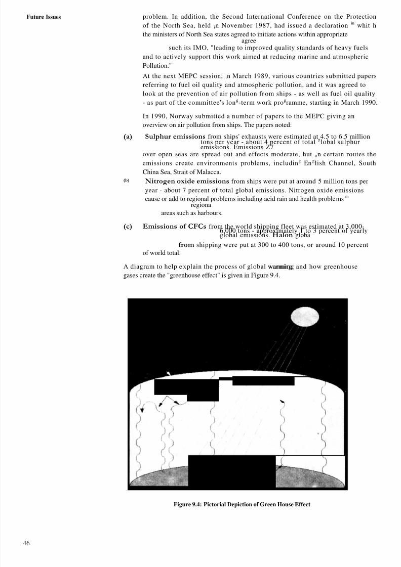
8/6/2019 IMU Future Issues
http://slidepdf.com/reader/full/imu-future-issues 45/123
46
Future Issues problem. In addition, the Second International Conference on the Protection
of the North Sea, held in November 1987, had issued a declaration in whit h
the ministers of North Sea states agreed to initiate actions within appropriateagree
such its IMO, "leading to improved quality standards of heavy fuels
and to actively support this work aimed at reducing marine and atmospheric
Pollution."
At the next MEPC session, in March 1989, various countries submitted papers
referring to fuel oil quality and atmospheric pollution, and it was agreed to
look at the prevention of air pollution fr om ships - as well as fuel oil quality
- as part of the committee's long-term work programme, starting in March 1990.
In 1990, Norway submitted a number of papers to the MEPC giving an
overview on air pollution from ships. The papers noted:
(a) Sulphur emissions from ships' exhausts were estimated at 4.5 to 6.5 milliontons per year - about 4 percent of total global sulphuremissions. Emissions Z7
over open seas are spread out and effects moderate, hut on certain routes the
emissions create environments problems, including En glish Channel, South
China Sea, Strait of Malacca.(b) Nitrogen oxide emissions from ships were put at around 5 million tons per
year - about 7 percent of total global emissions. Nitrogen oxide emissions
cause or add to regional problems including acid rain and health problems inregiona
areas such as harbours.
(c) Emissions of CFCs from the world shipping fleet was estimated at 3,000-6,000 tons - approximately 1 to 3 percent of yearlyglobal emissions. Halon globa
from shipping were put at 300 to 400 tons, or around 10 percent
of world total.
A diagram to help e xplain the process of global warming and how greenhousewarming
gases create the "greenhouse effect" is given in Figure 9.4.
5 sorne h«at is able topass through the gases.
Radiation
2.Planet's atmospherecontains Greenhouses
. o ar ra a on passesthrough the gases.. some ea us can
pass through a nd remainsatmosphere, adding to the
rises from the surface.
Figure 9.4: Pictorial Depiction of Green House Effect
8/6/2019 IMU Future Issues
http://slidepdf.com/reader/full/imu-future-issues 46/123
4l
Marpol Annexure V1Part — A: Prevention
of Air Pollution
9.4 FACTORS AFFECTING AIR POLLUTION
a) Green house gases add to natural 'greenhouse effect' causing global warming.The six green house gases are nitrous oxide (dinitrogen oxide or N2O) Carbondioxide, methane, hydro fluorocarbons (HFCs), per fluorocarbons (PFCs) andSulphur Hexafluoride (SF6). In November 2003, IMO adopted resolutionA.963(23) IMO Policies and practices related to the reduction of greenhouse gas
emissions from ships.
4 At its 52nd session in October 2004, the Marine Environment ProtectionCommittee made progress on developing draft Guidelines on the CO2 Indexing
Scheme and urged Members to carry out trials using the scheme and to report to thenext session. One purpose of developing guidelines on CO, emission indexing is todevelop a simple system that could be used voluntarily by ship operators during atrial period.
The Committee agreed that a CO2 indexing scheme should be simple and easy toapply and take into consideration matters related to construction and operation of theship, and market based incentives. At its 53rd session in July 2005, the MEPCapproved Interim Guidelines for Voluntar y Ship CO2 Emission b flexing for Use in
Trials.
Meanwhile, the Committee recognized that IMO guidelines on greenhouse gasemissions have to address all six greenhouse gases covered by the Kyoto Protocol(Carbon dioxide (CO2); Methane (CH4); Nitrous oxide (N20);
Hydrofluorocarbons (HFCs); Perfluorocarbons (PFCs); and Sulphur hexafluoride(SF6).
(b) Ozone is a gas composed of 3 atoms of oxygen. Sunlight and heat cause VolatileOrganic Compounds (VOCs) to react with Nitrogen Oxides (NOx) to form groundlevel ozone. This ground level ozone is bluish in color and is part of smog which isfound in urban areas. This can cause respiratory problems in human beings,damage crops and building materials. This also interferes with the production and
storage of food in plants and its overall health. The naturally occurred ozone whichis in the stratosphere (15 to 40 km above the earth surface) acts as a protectivelayer and prevents harmful UV rays from reaching the earths surface.
(c) Ozone depleting Substances (ODS): means the compounds that contribute tostratospheric Ozone depletion. These includes CFCs (chlorofluorocarbon) HCFCs(Hydro chlorofluorocarbons), Halon (a compound consisting of Methyl Bromide,Carbon tetrachloride and methyl chloroform). The Ozone layer in stratosphere isconstantly created and destroyed through natural cycles. When ODS reach they t h r o u g
it is broken down under intense UW light and chlorine or bromineatoms are released. These atoms accelerate the destruction process of ozoneresulting in a lower than normal ozone level. CFCs were widely used as
refrigerants and are prohibited from the date of entry in to force of Annex VI.HCFCs are chosen to replace CFCs and will he permitted till 01 January 2020 as itis less harmful compared to CFCs.
Ozone-depleting substance that may be found on board ship include, but not limited to:
Halon 1211 Bron chlorodifluoromethane
Halon 1301 Bromotrifluoromethane
Halon 2402 1,2-Dibromo- 1, 1,2,2-tetrafl uoroethene (also known as Halon 114B2)
CFC- I I Trichlorofluoromethane
CFC-12 Dichlorodifluoromethane
CFC-113 1, 1,2-Trichloro- 1,2,2-trifluoroethane
- - - -
8/6/2019 IMU Future Issues
http://slidepdf.com/reader/full/imu-future-issues 47/123
48
Future Issues CFC- 115 C h I oropent afl uoroethane
(d) Volatile Organic Components (VOCs): When Petroleum products or crude oil is
loaded or discharged from a ship a large quantity of lighter components from the cargo
are evaporated this oil vapor is known as VOCs or Volatile Organic Components.
Evaporation also occurs during voyage due to splashing of cargo with in the tank. As
per certain studies carried out it is estimated that, about 1 m tonnes of cargo is lost
due to this type of evaporation in one year. This also has a climatic impact of about 20
times greater than that of Carbon dioxide, one of the gases responsible for green house
effect.
'The main harmful substances produced In the combustion process are Nitrogen
oxides (NOx), Sulphurs oxides (SOX), Carbon dioxide. and Particulate matter
(soot). These are harmful to human health and environmental.Emission of NOx and SOX
can eventually cause acid,position wet or dr y (wet - rain, fog or snow and dry -
particles or gas). In gencral terms this is knownn as acid rain. One member of NOx,
nitrous oxide (NO) and Carbon dioxide green house gases. NOx also helps in
formation of ground level ozone.
Engine manufacturers are doing their best by entrancing the qualit y A engine
design in order to improve the emission standards. Another factor which affects the
quality of combustion is the fuel. The present day marine fuels are comparatively
cheap "end of the barrel" heavy fuels which are high in sulphur content. Lighter fuelswhich are low in sulphur content are more expensive and are in short supply. In order
to achieve cleaner emission the following are considered.
1. Scrubbing and cleaning the exhaust gases before it is let out to
atmosphere.
2. Switching to a better quality fuel when the ship is in an
environmentally fragile sea area.
3. Shutting down the power plant completely and plugging to shore
power while in environmentally sensitive ports.
9.5 ANNEX VI - REGULATIONS FOR THEPREVENTION OF AIR POLLUTION
This Annex entered into force on 19th May 2005.
Note: The following is a simplified version of the relevant regulations. Though everycare has been taken to maintain the meaning while interpreting, the original N version of therules is to be referred for any clarification.
Regulation 8
Form of Certificate
The International Air Pollution Prevention Certificate shall be drawn up in an official
language of the issuing country in the form corresponding to the model given in
appendix I to this Annex. If the language used is not English, French, or Spanish,
the text shall include a translation into one of these languages.
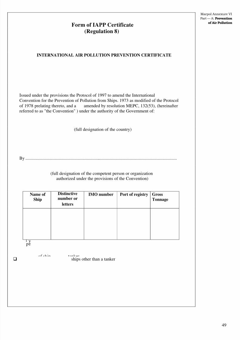
8/6/2019 IMU Future Issues
http://slidepdf.com/reader/full/imu-future-issues 48/123
49
Marpol Annexure VI
Part — A: Prevention
of Air Pollution
Form of IAPP Certificate(Regulation 8)
INTERNATIONAL AIR POLLUTION PREVENTION CERTIFICATE
Issued under the provisions the Protocol of 1997 to amend the InternationalConvention for the Prevention of Pollution from Ships. 1973 as modified of the Protocol
of 1978 prelating thereto, and a amended by resolution MEPC, 132(53), (hereinafterreferred to as "the Convention" ) under the authority of the Government of:
(full designation of the country)
By ........................................................................................................................................
(full designation of the competent person or organization
authorized under the provisions of the Convention)
Name of Ship
Distinctivenumber or
letters
IMO number Port of registry GrossTonnage
ype
ships other than a tanker

8/6/2019 IMU Future Issues
http://slidepdf.com/reader/full/imu-future-issues 49/123
50
Future Issues
THIS IS TO CERTIFY:
I That the ship has been surveyed in accordance with regulation 5 of AnnexVIof the Convention, and
2. That the survey ws that the equipment, systems, fittings, arrangements andmaterials fully comply with the applicable requirements of Annex VI of theConvention.
This certificate is valid until................... subject to surveys in accordance with regulation5 of Annex VI of the Convention.
Issued at (place of issue of certificate)
(Date of issue) (Signature of duly authorized official/ issuingthe certificate)
(Seal or stamp of the authority,as appropriate)

8/6/2019 IMU Future Issues
http://slidepdf.com/reader/full/imu-future-issues 50/123
51
Marpol Annexure V1Part - A: Prevention
of Air Pollution
I
Ar
ENDORSEMENT FOR ANNUAL AND INTERMEDIATE SURVEYS
THIS IS TO CERTIFY that at a survey required by regulation 5 of Annex VI of theConvention the ship was bound to comply with the relevant provisions of the Convention.
Annual survey: Signed.............................................................(Signature of duly authorized official)
Place ...............................................................
Date ................................................................
(Seal or stamp of the authority, as appropriate)
Annual*/ Intermediate* survey: Signed ...........................................................
(Signature of duly authorized official)
Place ...............................................................
Date ................................................................
J,
(Seal or stamp of the authority, as appropriate)
Annual*/ Intermediate* survey: Signed ...........................................................
(Signature of duly authorized official)
Place ...............................................................
Date ................................................................
(Seal or stamp of the authority, as appropriate)
Annual survey: Signed.............................................................
(Signature of duly authorized official)
Place ...............................................................Date ................................................................
(Seal or stamp of the authority, as appropriate)
* Delete as appropriate

8/6/2019 IMU Future Issues
http://slidepdf.com/reader/full/imu-future-issues 51/123
52
Future Issues Regulation 9
Duration and alidity of Certificate
(1) An International Air Pollution Prevention Certificate shall beisued fora periodspecified by the Administration, which shall not exceed five years from the date of issue subject to annual, intermediate and periodical surveys.
Regulation 12 – Ozone depleting substances
Annex VI prohibits any deliberate emissions of ozone-depleting substances andequipment containing such substances, shall be delivered to appropriate receptionfacilities when removed from a ship. New installations which contain ozone-depleting substances are prohibited on all ships after the entry into force date,except that new installations containing hydrochlorflourocarbons (HCFCs) arepermitted until
1 January 2020.
The use of Halon in fire extinguishing systems and equipment is already prohibitedfor new buildings. For new buildings, this requirement in Annex VI will thereforealways be complied with.
More restrictive requirements for ozone depleting substances are in placeregionally, e.g. in the European Union (EU).
Regulation 13 – Nitrogen Oxides (NOx)
Regulation 13 of Annex VI concerns NOx-emission from diesel engines and shallapply to:
− each diesel engine with a power output of more than 130 kW which is
installed on a ship constructed on or after I January 2000; and
− each diesel engine with a power output of more than 130 kW which
undergoes a major conversion on or after I January 2000.
This regulation does not apply to:
Emergency diesel engines, engines installed in life boats or for any
equipment intended to be used solely in case of emergency.
The phrase "major conversion ", means a modification of an engine where:
− the engine is replaced by a new engine built on or after I January 2000, or
− any substantial modification is made to the engine, as described in the NOx
Technical Code 1.3.2 (e.g. changing camshaft, fuel injection system, or any
other NOx-related settings or components), or
− the maximum continuous rating of the engine is increased by more than
10%
For this purpose, Substantial Modification is defined as follows:
For engines installed on vessels constructed on or after 1 January 2000, aSubstantial Modification means any modification to an engine that couldpotentially cause the engine to exceed the emission standards set out inRegulation 13 of Annex VI. Routine replacement of engine components byparts specified in the Technical File that do not alter emission characteristicsshall not be considered a "Substantial Modification", regardless of whether one
part or many parts are replaced.

8/6/2019 IMU Future Issues
http://slidepdf.com/reader/full/imu-future-issues 52/123
53
Marpol Annexure V IPart — A: Prevention
of Air Pollution
− For engines installed on vessels constructed before January 2000, aSubstantial Modification means any modification made to an engine whichincreases its existing emission characteristics established by the simplifiedmeasurement method as described below in excess of the allowances set outin the NOx Technical file. -These changes include, but are not limited to,changes in its operations or in its technical parameters (e.g. changingcamshaft, fuel injection systems, air systems, combustion chamberconfiguration, or timing calibration of the engine)
According to Annex VI the operation of applicable diesel engines are prohibitedexcept when the emission of nitrogen oxides from the engine is within thefollowing limits:
(i) 17,0 g /kWh when n is less than 130 rpm
(ii) 45,0 x 0.2) g/kWh when n is 130 or more but less than 2000 rpm
(iii) 9,8 g /kWh when n is 2000 rpm or more
where n = rated engine speed (crankshaft revolution per minute) and the emissionof nitrogen oxides are calculated as total weighted emission of NO2.
Figure 9.5
. Certification and Onboard Verification
The EIAPP (Engine International air pollution ) certificate is required for alldiesel engines as described above andll be issued for marine diesel engines after
demonstrating compliance with NOx emission limits. The certification process is tobe carried out in accordance with the NOx Technical Code issued by IMO.
Surveys and Inspections
Following the regime of the LAPP certificate, the diesel engines will also be subjectfor the following surveys:
− An initial survey before the ship is put into service or before the IAPPCertificate is issued for the first time.
Periodical surveys at intervals specified by the Administration, but notexceeding five years,
− A minimum of one intermediate survey during the period of validity of thecertificate.
NOX'Vk%%h
181614
Ltt
8 6
4
1)
Engine speed(RPM)
I
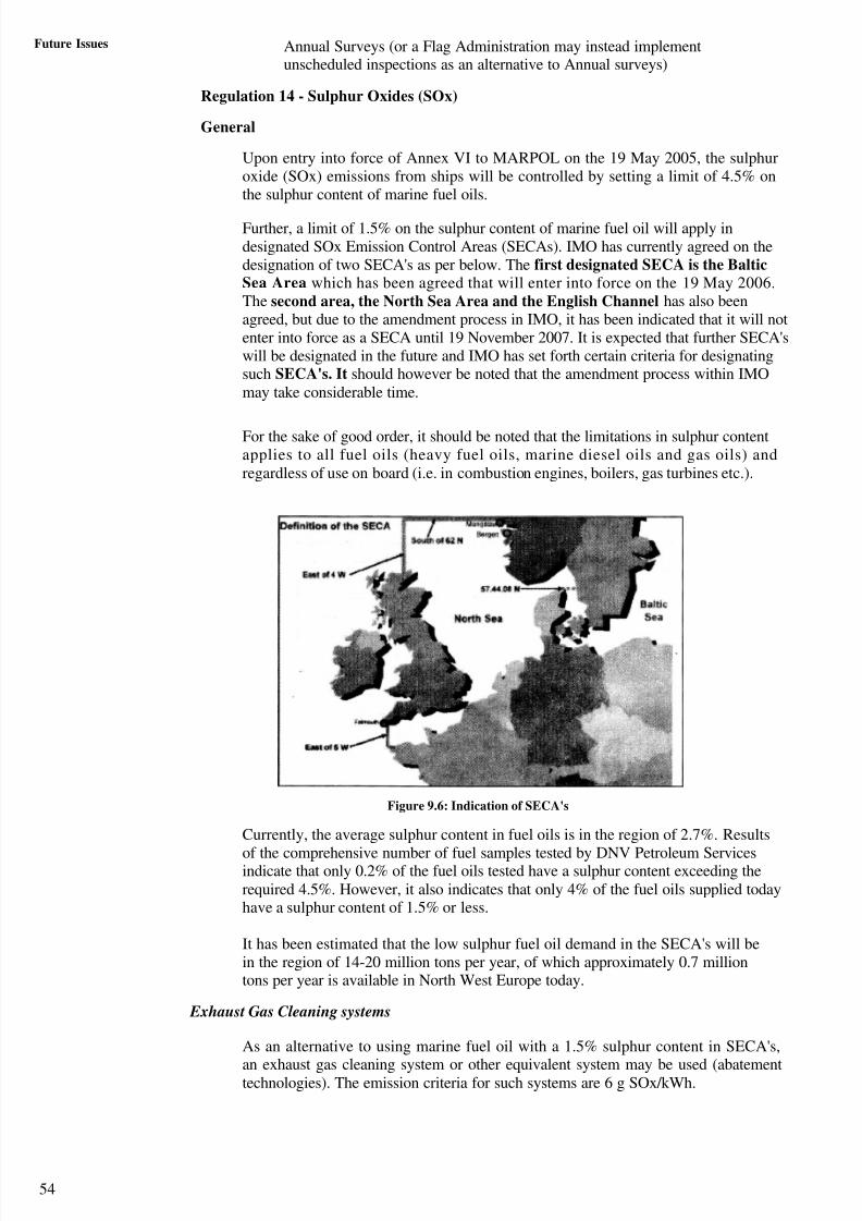
8/6/2019 IMU Future Issues
http://slidepdf.com/reader/full/imu-future-issues 53/123
54
Future Issues Annual Surveys (or a Flag Administration may instead implementunscheduled inspections as an alternative to Annual surveys)
Regulation 14 - Sulphur Oxides (SOx)
General
Upon entry into force of Annex VI to MARPOL on the 19 May 2005, the sulphuroxide (SOx) emissions from ships will be controlled by setting a limit of 4.5% onthe sulphur content of marine fuel oils.
Further, a limit of 1.5% on the sulphur content of marine fuel oil will apply indesignated SOx Emission Control Areas (SECAs). IMO has currently agreed on thedesignation of two SECA's as per below. The first designated SECA is the BalticSea Area which has been agreed that will enter into force on the 19 May 2006.The second area, the North Sea Area and the English Channel has also beenagreed, but due to the amendment process in IMO, it has been indicated that it will notenter into force as a SECA until 19 November 2007. It is expected that further SECA'swill be designated in the future and IMO has set forth certain criteria for designatingsuch SECA's. It should however be noted that the amendment process within IMOmay take considerable time.
For the sake of good order, it should be noted that the limitations in sulphur contentapplies to all fuel oils (heavy fuel oils, marine diesel oils and gas oils) andregardless of use on board (i.e. in combustion engines, boilers, gas turbines etc.).
Figure 9.6: Indication of SECA's
Currently, the average sulphur content in fuel oils is in the region of 2.7%. Results
of the comprehensive number of fuel samples tested by DNV Petroleum Servicesindicate that only 0.2% of the fuel oils tested have a sulphur content exceeding therequired 4.5%. However, it also indicates that only 4% of the fuel oils supplied todayhave a sulphur content of 1.5% or less.
It has been estimated that the low sulphur fuel oil demand in the SECA's will bein the region of 14-20 million tons per year, of which approximately 0.7 milliontons per year is available in North West Europe today.
Exhaust Gas Cleaning systems
As an alternative to using marine fuel oil with a 1.5% sulphur content in SECA's,
an exhaust gas cleaning system or other equivalent system may be used (abatementtechnologies). The emission criteria for such systems are 6 g SOx/kWh.

8/6/2019 IMU Future Issues
http://slidepdf.com/reader/full/imu-future-issues 54/123
55
W
Marpol Annexure VI
Part — A: Prevention
of Air Pollution
&-YAM.
Exhaust gas cleanings system
4
Figure 9.7
Development of a type approval standard for such systems is on goingin IRMO. Thecurrent available abatement technology is based on seawater scr ebbing principles.There is however a few concerns related to these types of scrubber bbertype systems:
Annex VI states that port states may prohibit discharge of scrubbereffluent overboard in ports within SECA's unless it can be documentedthat the effluent complies with criteria set by that port state. A mitigatingmeasure is installation of filtration/treatment systems.
It has been indicated that conventional scrubber technology may hestruggling to meet the emission criteria at high exhaust gas discharge flows.
Its has been indicated that there is a risk of blue-sheen originating from thescrubber overboard discharge. Although, not necessarily constituting anenvironmental hazard, the mere risk of such occurrences is to some operatorsunacceptable.
There are space considerations in the engine room and more specifically thefunnel. Although it has been indicated that the more advanced scrubbertypes can replace standard silencers, the associated piping systems mayrepresent a challenge. Pressure drop in scrubbers has also been indicated asa limitation, particular in way of main engines uptakes.
Tanker owners have had mixed experiences with corrosion of inert gasscrubbers and associated piping systems.
ow Sulphur Heavy Fuel
It has been indicated that experience in terms of low sulphur residual (or heavy) fueloil blending is varying and that quality problems are to be expected. Although thereis limited usage of (blended) low sulphur fuel oils, low sulphur processing of fuel oilsmay lead to additional quality problems such as instability,
incompatibility, ignition and combustion difficulties and an increase of catalytic fineslevels. Regrettably one has also seen cases where chemical waste has beenintroduced in such fuel. In light of the required demand for low sulphur fuel oils,there have also been concerns over the potential increase of sulphur content in highsulphur fuel oils.
uel tank/system configuration
It should be noted that when approaching a SECA the fuel must be changedover to the 1.5% sulphur content fuel and completed before entering theSECA.

8/6/2019 IMU Future Issues
http://slidepdf.com/reader/full/imu-future-issues 55/123
Future Issues For ships with standard fuel oil system configurations (one service and settling
tank), this will involve filling of settling tanks with low sulphur fuel oil, adequatefuel treatment of same and subsequent filling of service tank, as well as flushing of the fuel service piping systems of high sulphur fuel oil.
The current problems with incompatibility between heavy fuel oils, and betweenheavy fuel oils and marine diesels are not expected to disappear with increased
demands for low sulphur heavy fuel oils (excessive sedimentation/sludging andseparator and filter problems).
Figure 9.8
Considering the differences in cost, some owners are installing an additional set of
service and settling tanks for low sulphur fuel oils. Additional bunker tanks areconsidered installed for the same reasons. Such measures would also simplifychange-over procedures and bunker management. Inadequate availability of lowsulphur heavy fuel oils may force owners to increase the consumption of low sulphurdiesel oils within SECA's.
Owners will therefore have to assess whether the diesel oil tank capacity needs tobe upgraded. The differences in cost between low and high sulphur heavy fuel oils aswell as between heavy fuel oils and low sulphur diesel oils, has led some owners toconsider separating fuel treatment and service piping systems. This isincreasingly important with respect to potential requirements to use of ultra lowsulphur fuels in EU ports (Auxiliary engines and boilers).
In order to facilitate safe and simple change-over, the installation of separatemarine gas oil/diesel oil supply piping with heating capabilities should be
tank r r a 2 T..k Tank
Po,sstbie arrangementditional fueloil tanks
The below shows the arrangement of fuel oil tank piping arrangement as per theoptional DNV class notation FUhich enables handling of different fuel qualities.
0-0— Pipo
-- t
MF (I ';ij;w ' my " 'weak,T " k
t.t~q _tank lank
tvA ITITank
T. 1.2 tux 24 lip,—j$— MCR
ta.* To
F - 4 .0PLICOWt
H'I'dfing of Jiflersni fuels.
8/6/2019 IMU Future Issues
http://slidepdf.com/reader/full/imu-future-issues 56/123
Annexure V1Part — A: Prevention
of Air Pollution
considered. (While separate direct diesel oil supply lines are often arranged forauxiliary diesel engines, the same is less frequently encountered for boilers andmain engines.)
The below serves as examples of proposed modifications regarding duplicatedheavy fuel oil service and settling tanks and piping systems.
Change-over procedures
Change-over between heavy fuel oil grades is standard practice and so is changeoverfrom heavy fuel oil to marine diesel oil in connection with e.g. drydockings. Change-
over from heavy fuel oil to marine gas oil is however completely different andclearly not common standard. If gas oil is mixed in while the fuel temperature is stillvery high, there is a high probability of gassing in the fuel oil service system withsubsequent loss of power.
It should be acknowledged that the frequency and timing of such change-over mayincrease and become far more essential upon entry into force of SECA's and the EUproposed amendments
Additionally, the time, ship's posit ons at the start and completion of change-over toand from 1.5% fuel oil must be recorded in a logbook (e.g. ER log. book), togetherwith details of the tanks involved and fuel used. It can be anticipated that the same
will be applicable with respect to the EU proposal upon entry into force.
Bunker management
In view of the change-over requirements, bunker grade segregation constraints,uncertainty in terms of low-sulphur fuel oil availability and potential qualityproblems, the flexibility in bunker management may be impaired. In addition to thepotential increase in fuel oil cost, it could also result in increased frequency of bunkering.
Further, owners/managers and charterers may need to amend their bunkerspecifications, fuel supply agreements as well as charter parties to take the newrequirements into account.
Regulation 15 — Volatile Organic Compounds
Emissions of volatile organic compounds (VOCs) from tankers may by each party toAnnex VI be regulated in its ports and terminals. Such requirements shall be givenin a list published by IMO. The list shall also specify size of tankers, and whichcargoes, that requires vapour emission control system.
All tankers which are subject to vapour emission control in accordance with abovelist shall be provided with an approved vapour collection system, and shall use suchsystem during the loading of such cargoes.
Existing tankers which are not fitted with vapour collection systems may beaccepted for a period of three years after the terminal was included in the above list.DNV has for many years had class notations VCS 1 and 2 for vapour controlsystems complying with IMO Guidelines (MSC/Circ.585), and USCG regulations. Itmay be noted that a vessel complying with VCS- 1 or 2 will comply with regulation15. This regulation shall oilyapplyarriers when the type of loading and containmentsystems allow safe retention ofon-methane VOCs on board, or their safe returnashore.
Regulation 16 — Shipboard Incineration
Onboard incineration outside an incinerator is prohibited except that sewage sludgeand sludge oil from oil separators may be incinerated in auxiliary power plants andboilers when the ship is not in ports, harbours and estuaries.
Incineration of Annex 1,11 and Ill cargo residues, of PCB's (Polychlorinatedbiphenyls), of garbage containing more than traces of heavy metals and of refinedpetroleum products containing halogen compounds is always prohibited.
haloge 57
8/6/2019 IMU Future Issues
http://slidepdf.com/reader/full/imu-future-issues 57/123
Future Issues Incineration of PVC's (polyvinyl chlorides) is prohibited except in shipboard
incinerators type approved according to resolutions MEPC 59(33) orMEPC 76(40).
Monitoring of combustion flue gas outlet temperature shag required at all timesand waste shall not be fed into a continuous-feed shipboard incinerator when thetemperature is below the minimum allowed temperature of 850°C. For batch-loadedshipboard incinerators, the unit shall be designed so that the temperature in thecombustion chamber shall reach 600°C within 5 minutes after start-up. It must beensured that the incinerators' flue gas outlet temperature monitoring system is
operational.
All incinerators installed on or after I January 2000 shall be type approved inaccordance with Resolution MEPC 76(40) giving the IMO standard specification forshipboard incinerators. For such incinerators a manufacturer's operating manual isrequired.
Regulation 18 – Fuel Oil Quality
General
While fuel oil quality is currently primarily a matter between owners/managers(and charterers) and suppliers, it will under Annex VI of MARPOL 73/78 also
become a statutory matter.In addition to requirements limiting the sulphur content of oil fuel, Annex VIcontains requirements preventing the incorporation of potentially harmfulsubstances, and in particular waste streams (e.g. chemical waste), into fuel oils.
Regulation 18 specifically requires that fuel oil supplied to ships is to be free frominorganic acids or chemical wastes that could jeopardise the safety of the ship, beharmful to ships' personnel, or which would contribute overall to additional airpollution. The addition of small amounts of additives intended to improveperformance is however permitted.
It has been indicated that Regulation 18 may be enforced in case a ship is involved
in accidents or near-accidents where fuel quality is a suspected contributor.
Bunker delivery notes
It is a requirement of Regulation 18 that any fuel oil for combustion purposesdelivered to and used onboard shall be recorded by means of a Bunker Delivery Note(BDN). This implies that a bunker delivery note shall be presented for every bargedelivery and every grade.
Bunker Delivery Notes are required to contain all specific information as follows:
− Name and IMO number of receiving ship
− Bunkering port
− Date of conmmencement of bunkering
− Name, address, and telephone number of marine fuel oil supplier
− Product name
− Quantity (metric tons)
− Density at 15 oC (kg/m3)
− Sulphur content (% m/m)
− A declaration signed and certified by the fuel oil supplier's representative thatthe fuel oil supplied is in conformity with regulation 14 and 18 (Le. that the
fuel supplied has a sulphur level below 4.5% and that the fuel is freefrom inorganic acid, does not include any added substance or chemical waste 5

8/6/2019 IMU Future Issues
http://slidepdf.com/reader/full/imu-future-issues 58/123
Marpol Annexure VI
Part — A: Prevention
of Air Pollution
which either jeopardises the safety of ships, adversely affects theperformance of the machinery, is harmful to personnel, or contributes overall toadditional air pollution). Further, Resoiution MEPC.96(47) recommends thatthe seal number of the associated MARPOL Annex VI fuel sample is includedin the BDN's for crossreference purposes.
The BDN's are to be kept on board and readily available for inspection at all times. Itshall be retained fora period of three years after the fuel oil has been delivered on
board.4
MARPOL 73/78 Annex VI fuel oil samples
Regulation 18 requires that every BDN is to be accompanied by a representativesample of the fuel oil delivered, taking into account the guidelines in ResolutionMEPC.96(47).
The sample is to be sealed and signed by the supplier's representative and the masteror officer in charge of the bunker operation on completion of bunkering operations,and retained under the ship's control until the fuel oil is substantially consumed, but inany case fora period of not less than 12 months from the time of delivery. For thesake of good order it should be noted that the practical purpose of this sample is to
enable port states to verify the sulphur content of the fuel, as well as to verify that thefuel oil quality is in accordance with Regulation 18.
As Annex VI specifies that the Annex VI sample is not to be used for commercialpurposes, DNV Petroleum Services recommends that for ship's alreadyparticipating in a fuel oil quality testing scheme, the Annex VI sample should be thefourth sample (in addition to the sample sent to laboratory for testing, supplierssample and the retained onboard sample). The reason is that it is considered anadvantage to always have a MARPOL Annex VI sample onboard in case of port statecontrols.
Sampling procedures
Note that the referred to Resolution MEPC.96(47) specifies in detail that the fuelsample is to be obtained at the receiving ship's inlet bunker manifold and is to bedrawn continuously throughout the bunker delivery period. The term continuouslydrawn is specified to mean a continuous collection of drip sample throughout thedelivery of bunker fuel. Sampling methods are further clarified as either; manualvalve-setting continuous-drip sampler (equivalent to DNV Petroleum Services'Line sampler), time-proportional automatic sampler, or flow-propor tionalautomatic sampler.
Figure 9.9
Further the guidelines specify that sample bottle labels are to contain the followingnformation:

8/6/2019 IMU Future Issues
http://slidepdf.com/reader/full/imu-future-issues 59/123
5,9
Future Issues Location at which, and the method by which, the sample was drawn
Bunkering date
Name of bunker tanker/bunker installation
Name and IMO number of the receiving ship
Signatures and names of the supplier's representative and the ship'srepresentative
Details of seal identification
Bunker grade.
Sample inventory
Resolution MEPC.96(47) also contains recommendations on sample storage location.Specifically the samples are to be kept in a safe storage location, outside the ship'saccommodation and where personnel would not be exposed to vapours which may bereleased from the sample. Further, the retained sample should be stored in a shelteredlocation where it will not be subject to elevated temperatures, preferably at acool/ambient temperature, and where it will not be exposed to direct sunlight.
On tankers, the cargo sample locker would be considered an adequate storage space.Alternatively, a suitable locker (with opening ensuring adequate air flow) in anadequately ventilated area of the engine room located at a safe distance from ignitionsources and hot surfaces may be considered The above guideline also recommendsthat an inventory system is developed (e.g. log book) to keep track of the retainedsamples.
Supplier's responsibility
While most IMO conventions place full responsibility on the ships and shipowners,Regulation 18 places a certain responsibility on the suppliers (fuel oil qualitydeclaration, BDN and the Annex VI fuel oil sample by continuous drip and at the
receiving ships manifold).Annex VI of MARPOL also contains instruments to encourage port states to ensurethat suppliers fulfill their obligations. Port states are therefore required to:
Maintain a register of local suppliers of fuel oil;
Figure 9.10
Require local suppliers to provide the BDN and sample, certified by the fuel oiloil supplier that the fuel oil meets the requirements of regulations 14 and 18.

8/6/2019 IMU Future Issues
http://slidepdf.com/reader/full/imu-future-issues 60/123
Marpol Annexure VI
Part — V: Prevention
of Air Pollution
Require local suppliers to retain a copy of the bunker delivery note for atleast three years for inspection and verification by the Port State asnecessary;
Take action as appropriate against fuel oil suppliers that have been found todeliver fuel oil that does not comply with that stated on the Bunker Delivery
Note;
Inform the Flag Administration of any ship receiving fuel oil found to be
noncompliant with the requirements of regulations 14 or 18 of this Annex.
Inform IMO for transmission to Parties to the Protocol of 1997 of all caseswhere fuel oil suppliers have failed to meet the requirements specified inregulations 14 or 18. However, despite the suppliers' responsibilities and theinstruments available, previous experience from Port State Controlsindicates that it is advisable for owners/managers themselves to ensurecompliance. In order to assist ships in ensuring that the operationalrequirements are met, it should be considered to include clauses related toMARPOL Annex VI compliance in bunker contracts and agreements withsuppliers, as well as charter parties.
Third party inspections
It can be expected that upon implementation, class surveyors, port state inspectorsand possibly also vetting inspectors will scrutinise onboard documentation andrecords (e.g. sampling procedures, change-over procedures, ER log books, BDN's,sample inventory log books etc.), as well as the fuel oil sample inventory.Consultations with port states indicate that analysis of the onboard Annex VIsamples will be carried out upon suspicion, e.g. in case of an accident or nearaccident.
Based on experiences with port state inspectors scrutinising of oil record books relatedto sludge and oily bilge water inventory and balance, owners and managers couldexpect that similar practice could be applied with respect to high-sulphur and low-sulphur fuel movements and consumption when operating in SECA's or the EU(bunker quantity is required specified in BDN's). Accordingly, it is advisable thatcrews are instructed and trained to thoroughly verify that the supplied quantity is inaccordance with that specified in the BDN's, or alternatively that independent bunkerquantity surveyors are hired for this purpose. Consultations with some port statesindicate that they will require compliance as of 19 May 2005. Owners and managersare advised to ensure compliance accordingly.
However, fuel oil quality testing represents a proactive approach, both in terms of verifying compliance prior to any port state control, and more importantly as asafeguard against the adverse effects of poor fuel oil quality in combustion
machinery. Hopefully, third parties may also consider test reports from a reputableand accredited independent testing laboratory as equivalent to additional testing of onboard samples.
Further participation in such a scheme ensures that ships have access to compliantsampling equipment (sample bottles, seals, line samplers and cubitainers).
SAQ 1
(a) What is air pollution and what are its sources?
(b) What is the objective of Annex VI of Marpol? What forms of air pollutiondoes it address?
(c) What were the initial legislative initiatives taken to address air pollutionfrom ships?

8/6/2019 IMU Future Issues
http://slidepdf.com/reader/full/imu-future-issues 61/123
62
Future Issues (d) What points were required to be reviewed by INTO during its 54th Session k Anw.r.t air pollution?
(e) What are the following
(i) GAG'S
(ii) Ozone
(iii) ADS
(iv) VOC's(f) What is IAPP? On what conditions is it issued? What is its validity?
(g) What are the various surveys a vessel is subject to be eligible for an IAPPC?
(h) What are the methods of verification of compliance with Regulation 13 of Annex VI w.r.t NOx emissions? Briefly describe each one.
(i What are SECAS? Name the SECAS in force at the present time. Brieflydiscuss the concerns involved with fuel changeover when vessels enterSECAS.
0) Briefly discuss the revised bunkering and sampling procedures in
compliance with Annex VI including reference to BDN, its contents andsignificance.
9.6 SUMMARY
Reducing Sulphur emissions and, controlling emissions of Nitrogen Oxides and volatile
organic compounds has been a major concern of the environmental authorities ies worldwidefor over three decades. Under the auspices of the United Nations, many nations have alsoagreed to but consumption and production of chlorofluorocarbons (CFCs) and haloes whichare ozone-depleting substances.
In this unit, we have seen that Marpol Annex VI sets limits on Sulphur Oxide and NitrogenOxide emissions from ship exhausts and prohibits deliberate omissions of ozone depletingsubstances. The Marine environment protection committee (MEPc) of the IMO has broughtout number of amendments to MARPOL Annex VI.
In this unit we have also familiarized burselves about the shipboard incineration,available methods to control air pollution and briefly, solutions for producing cleaner
energy
62
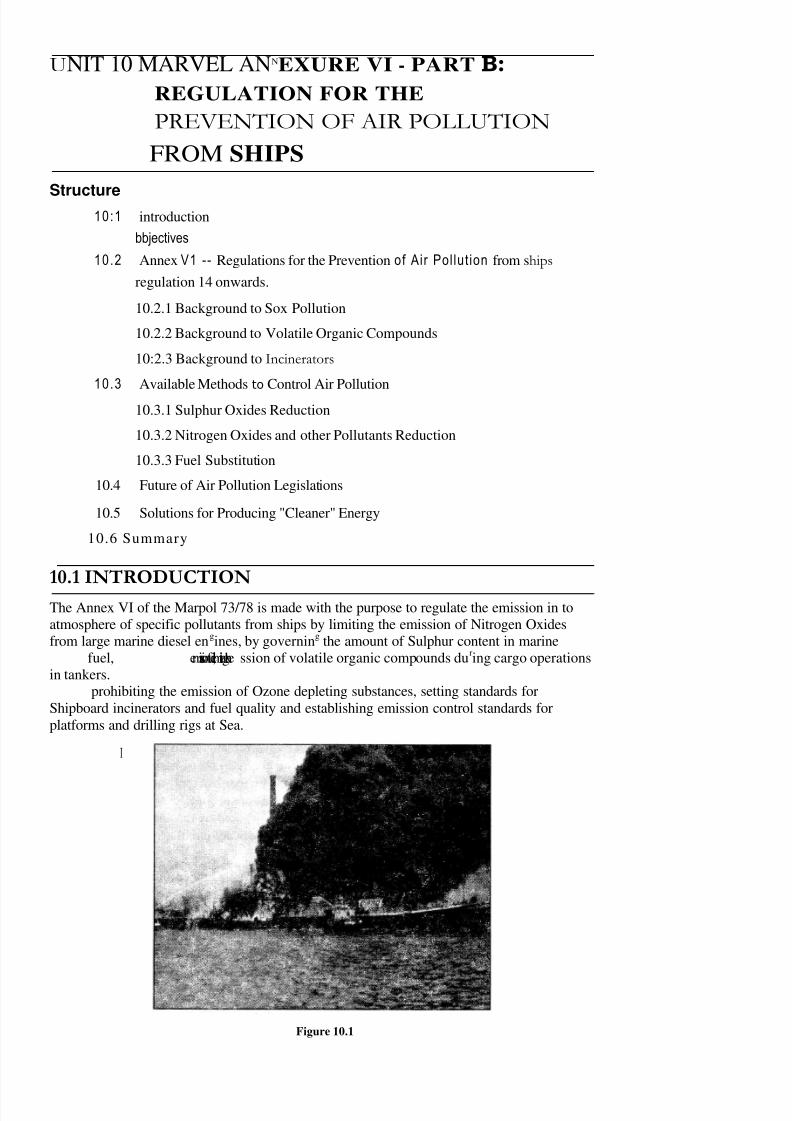
8/6/2019 IMU Future Issues
http://slidepdf.com/reader/full/imu-future-issues 62/123
UNIT 10 MARVEL ANNEXURE VI - PART B:
REGULATION FOR THE
PREVENTION OF AIR POLLUTION
FROM SHIPS
Structure10:1 introduction
bbjectives
10.2 Annex V1 -- Regulations for the Prevention of Air Pollution from ships
regulation 14 onwards.
10.2.1 Background to Sox Pollution
10.2.2 Background to Volatile Organic Compounds
10:2.3 Background to Incinerators
10.3 Available Methods to Control Air Pollution
10.3.1 Sulphur Oxides Reduction
10.3.2 Nitrogen Oxides and other Pollutants Reduction
10.3.3 Fuel Substitution
10.4 Future of Air Pollution Legislations
10.5 Solutions for Producing "Cleaner" Energy
10.6 Summary
10.1 INTRODUCTION
The Annex VI of the Marpol 73/78 is made with the purpose to regulate the emission in toatmosphere of specific pollutants from ships by limiting the emission of Nitrogen Oxidesfrom large marine diesel engines, by governing the amount of Sulphur content in marine
fuel, emissionfuel,limitingthe ssion of volatile organic compounds during cargo operationsin tankers.
prohibiting the emission of Ozone depleting substances, setting standards forShipboard incinerators and fuel quality and establishing emission control standards forplatforms and drilling rigs at Sea.
I
Figure 10.1
8/6/2019 IMU Future Issues
http://slidepdf.com/reader/full/imu-future-issues 63/123
64
Future Issues Objectives
After studying , this unit you shall be able to:
• briefly enumerate Regulations 14,15,16,17,18 & 19 of Marpol Annexure – VIand Regulations
• state as to how sulphur and nitrogen oxides, and volatile organic compoundscan harm your health.
10.2 ANNEX VI — REGULATIONS FOR THEPREVENTION OF AIR POLLUTION FROM
Regulation 14
Sulphur oxides (SOx)
General requirements
( I) The sulphur content of any fuel oil used on board ships shall not exceed4.5
% m/m.
The worldwide averag e SUIP111.11'content of residual fuel oil supplied for use on boardA-
ships shall be monitored taking into account guidelines to be developed by theOrganization.
Requirements within SOx emission control areas
(3) For the purpose of this regulation, SOx emission control areas shall include:
(a) the Baltic Sea area as defined in regulation 10(l)(b) of Annex 1, the North Sea Area as defined in regulation 5(1)(f) of Annex V and
(b) any other sea area, including port areas, designated by the Organization inaccordance with criteria and procedures for designation of SOx emissioncontrol areas with respect to the prevention of air pollution from shipscontained in appendix III to this Annex.
(4) While shill are within SOx emission control areas, at least one of the following conditions shall be fulfilled:
(a) the sulphur content of fuel oil used on board ships in a Sox emission controlarea does not exceed 1.5% m/m
(b) an exhaust gas cleaning system, approved by the Administration taking intoaccount guidelines to be developed by the Organization, is applied to reducethe total emission of sulphur oxides from ships, including both auxiliary andmain propulsion engines, to 6.0 g SOx/kW h or less calculated as the total weig htof sulphur dioxide emission. Waste streams from the use of such equipment shallnot be discharged into enclosed ports, harbours and estuaries unless it can bethoroughly documented by the ship that such waste streams have no adverseimpact on the ecosystems of such enclosed ports, harbours and estuaries, basedupon criteria communicated by the authorities of the port State to theOrganization. The Organization shall circulate the criteria to all Parties to theConvention; or
(c) any other technological method that is verifiable and enforceable to limit SOxemissions to a level equivalent to that described in sub-paragraph (b) is applied. These methods shall be approved by the Administration taking into accountguidelines to be developed by the Organization.
Z~
(5) The sulphur content of fuel oil referred to in paragraph (1) and paragraph (4)(a) of this regulation shall be documented by the supplier as required by regulation 18 of
this Annex.
(6) Those ships using separate fuel oils to comply with paragraph (4)(a) of thisregulation shall allow sufficient time for the fuel oil service system to be fully
64
(2)
8/6/2019 IMU Future Issues
http://slidepdf.com/reader/full/imu-future-issues 64/123
65
Marpol Annexure VI
Pail — B: Regulation forthe Prevention or Air
Pollution from Ships
flushed of all fuels exceeding 1.5% m/m sulphur content prior to entry into a SOxemission control area. The volume of low sulphur fuel oils (less than or equal to 1.5%sulphur content) in each tank as well as the date, time, and position of the ship whenany fuelchangeover operation is completed, shall be recorded in such logbook asprescribed by the Administration.
(7) During the first 12 months immediately following entry into force of the presentProtocol, or of an amendment to the present Protocol designating a specific SOxemission control area under paragraph (3)(b) of this regulation, ships entering a SOx
emission control area referred to in paragraph (3)(a) of this regulation or designatedunder paragraph (3)(b) of this regulation are exempted from the requirements inparagraphs (4) and (6) of this regulation and from the requirements of paragraph (5) of this regulation insofar as they relate to paragraph (4)(a) of this regulation.
10.2.1 Background to Sox Pollution
SOx and the fine particulate products of their transformation sulphates and acidaerosolscause a variety of negative impacts on people and the environment. This includesdirect health damage, mainly related to the respiratory system, which is most severe forasthmatic children. S02 emissions also cause reduced visibility, corrosion of materials,reduced agricultural production and soiling. SOx emissions are a major contributor to acidprecipitation. One beneficial impact is the cooling effect of aerosols resulting from SOxemissions. The cooling has offset a significant part of the greenhouse warming over the
cooling significanhemisphere, where SOx pollution is most severe.
Regulation 15
Volatile Organic Compounds
(1) If the emissions of volatile organic compounds (VOCs) from tankers are to beregulated in ports or terminals under the jurisdiction of a Party to the Protocol of 1997, they shall be regulated in accordance with the provisions of this regulation.
regulated regulation
A Party to the Protocol of 1997 which designates ports or terminals under its
jurisdiction in which VOCs emissions are to be regulated, shall submit a notification
to the IMO. This notification shall include information on the size of tankers to becontrolled, on cargoes requiring vapour emission control systems, and the effectivedate of such control. The notification shall be submitted at least six months before theeffective date.
The Government of each Party to the Protocol of 1997 which designates ports orterminals at which VOCs emissions from tankers are to be regulated shall ensurethat vapour emission control systems, approved by that Government taking into
account the safety standards developed by the Organization, are provided in portsand terminals designated, and are operated safely and in a manner so as to avoidundue delay to the ship.
(4) The Organization shall circulate a list of the ports and terminals designated by the
designateto the Protocol of 1997 to other Parties to the Protocol of 1997 and MemberStates of the Organization for their information.
All tankers which are subject to vapour emission control in accordance with theprovisions of paragraph (2) of this regulation shall be provided with a vapour collectionsystem approved by the Administration taking into account the safety standardsdeveloped by the Organization, and shall use such system during the loading of suchcargoes. Terminals which have installed vapour emission control systems inaccordance with this regulation may accept existing tankers which are not fitted withvapour collection systems for a period of three years after the effective date identifiedin paragraph (2).
(6) This regulation shall only apply to gas carriers when the type of loading andcontainment systems allow safe retention of non-methane VOCs on board, or theirsafe return ashore.
(3)
(5)

8/6/2019 IMU Future Issues
http://slidepdf.com/reader/full/imu-future-issues 65/123
66
Future Issues
Figure 10.2
10.2.2 Background to Volatile Organic Compounds
Volatile organic compounds change easily from liquid form to vapor.
What are Volatile Organic Compounds?
Organic compounds are chemicals that contain carbon and are found in all living thin gs.C~
Volatile organic compounds, sometimes referred to as VOCs, are organic compounds thateasily become vapors or gases. Along with carbon, they contain elements such ashydrogen, oxygen, fluorine, chlorine, bromine, sulfur or nitrogen.
Volatile organic compounds are released from burning fuel, such as gasoline., wood, coal,or natural gas. They are also released from solvents, paints, glues, and other products thatare used and stored at home and at work.
Many volatile organic compounds are also hazardous air pollutants. Volatile organiccompounds, when combined with nitrogen oxides, react to form ground-level ozone, orsmog.
Examples of volatile organic compounds are gasoline, benzene, formaldehyde, solventssuch as toluene and xylene, and perchloroethylene (or tetrachloroethylene), the mainsolvent used in dry cleaning.
Many volatile organic compounds are commonly used in paint thinners, lacquer thinners,moth repellents, air fresheners, hobby supplies, wood preservatives, aerosol sprays,degreasers, automotive products, and dry cleaning fluids.
How might I be exposed to Volatile Organic Compounds?
You can be exposed to volatile organic compounds outdoors by breathing polluted air thatcontains them. You are most likely to be exposed to volatile organic compounds outdoorsin the summer, when the sun and hot temperatures react with pollution to form smog,
Indoors, products that contain volatile organic compounds release emissions when you usethem, and to a smaller degree, when they are stored. You can be exposed to volatile organiccompounds at home if you use cleaning, painting, or hobby supplies that contain them.You can also be exposed if you dry-clean your clothes with home dry-cleaning products; if you dry-clean your clothes at a professional dry-cleaners; or if you use graphics and craftsmaterials such as glues, permanent markers, and photographic solutions.
How can Volatile Organic Compounds affect my Health?
The health effects of volatile organic compounds can vary greatly according to thecompound, which can range from being highly toxic to having no known health effects.The health effects of volatile organic compounds will depend on nature of the volatileorganic compound, the level of exposure, and length of exposure.
Benzene is known to be a human carcinogen; formaldehyde and perchloroethylene are 11
reasonably. anticipated to be carcinogens." People at the highest risk of long-term
8/6/2019 IMU Future Issues
http://slidepdf.com/reader/full/imu-future-issues 66/123
67
Marpol Annexure ViPart - B: Regulation for
the Prevention of Air
Pollution from
to these three volatile organic compounds are industrial workers who have prolonged exposureto the compounds in the workplace; cigarette smokers; and people who ha% e prolongedexposure to emissions from heavy motor vehicle traffic.
Long-term exposure to volatile organic compounds can cause damage to the liver, kidneysand central nervous system.
Short-term exposure to volatile organic compounds can cause eye and respiratory tractirritation, headaches, dizziness, visual disorders, fatigue, loss of coordination, allergic skinreactions, nausea, and memory impairment.
Figure 10.3Regulation 16
Shipboard incineration
(1) Except as provided in paragraph (5), shipboard incineration shall be allowed only ina shipboard incinerator.
(2) (a) Except as provided in sub-paragraph (b) of this paragraph, each incineratorinstalled on board a ship on or after I January 2000 shall meet the requirementscontained in appendix IV to this Annex. Each incinerator shall be approved by theAdministration taking into account the standard specifications for shipboardincinerators developed by the Organization. {(b) The Administration may allow
exclusion from the application of sub-paragraph (a) of this paragraph to anyincinerator which is installed on board a ship before the date of entry into force of the Protocol of 1997, provided that the ship is solely engaged in voyages withinwaters subject to the sovereignty or jurisdiction of the State the flag of which theship is entitled to fly.
(3) Nothing in this regulation affects the prohibition in, or other requirements of, theConvention on the Prevention of Marine Pollution by Dumping of Wastes and OtherMatter, 1972, as amended, and the 1996 Protocol thereto.
(4) Shipboard incineration of the following substances shall be prohibited:
(a) Annex I, II and ICI cargo residues of the present Convention and related
contaminated packing materials;(b) polychlorinated biphenyls (PCBs);
(c) garbage, as defined in Annex V of the present Convention, containing morethan traces of heavy metals; and
(d) refined petroleum products containing halogen compounds.
(5) Shipboard incineration of sewage sludge and sludge oil generated during the normaloperation of a ship may also take place in the main or auxiliary power plant or boilers,but in those cases, shall not take place inside ports, harbours and estuaries.
(6) Shipboard incineration of polyvinyl chlorides (PVCs) shall be prohibited, except inshipboard incinerators for which IMO Type Approval Certificates have been issued.
(7) All ships with incinerators subject to this regulation shall possess a manufacturer'soperating manual which shall specify how to operate the incinerator within the limitsdescribed in paragraph 2 of appendix IV to this Annex.

8/6/2019 IMU Future Issues
http://slidepdf.com/reader/full/imu-future-issues 67/123
68
ture Issues
Personnel responsible for operation of any incinerator shall be trained and capable of implementing the guidance provided in the manufacturer's operating manual.
o p e r a t i n g
Monitoring of combustion flue gas outlet temperature shall be required at all timesand waste shall not be fed into a continuous-feed shipboard incinerator when thetemperature is below the minimum allowed temperature of 850°C. For batch-loadedshipboard incinerators, the unit shall be designed so that the temperature in thecombustion chamber shall reach 600°C within five minutes after start-up.
(10) Nothing in this regulation precludes the development, installation and operation of alternative design shipboard thermal waste treatment devices that meet or exceed the
requirements of this regulation.
10.2.3 Background to Incinerators
Incineration is a solid waste treatment technology involving burning waste at very hightemperatures. Incineration and other high temperature waste treatment systems are describedas "thermal treatment". In effect, incineration of waste materials converts the waste intoheat, gaseous emissions to the atmosphere and residual ash. Incineration has a number of outputs such as the ash and the emission to the atmosphere of combustion product gases andparticulate matter.
Figure 10.4 : An Incineration plant
Gaseous Emissions
The combustion product gases exhausted to the atmosphere by incineration are a sourceof concern. The main pollutants in the exhaust gases include acid gases such ashydrogen chloride, sulphur dioxide, nitrogen oxides (referred to as NOx), and carbondioxide.
Solid Outputs
Incineration produces fly ash and bottom ash just as is the case when coal iscombusted. The fly ash, by far, constitutes more of a potential health hazard thandoes the bottom ash because the fly ash contains toxic metals such as lead, cadmium,copper and zinc as well as small amounts of dioxins and furans.
The bottom ash may or may not contain significant levels of health hazardousCN
materials.
Regulation 17
Reception facilities
I The Government of each Party to the Protocol of 1997 undertakes to ensure theprovision of facilities adequate to meet the:
(a) needs of ships using its repair ports for the reception of ozone depleting ubstancesusing and equipment containing such substances when removed from ships;
(b) needs of ships using its ports, terminals or repair ports for the reception of exhaustusing gas cleaning residues from an approved exhaust gas cleaning system when discharge
(8)
(9)

8/6/2019 IMU Future Issues
http://slidepdf.com/reader/full/imu-future-issues 68/123
Marpol Annexure VI
Part — B: Regulation forthe Prevention of AirPollution from Ships
into the marine environment of these residues is not permitted under regulation 14 of this Annex; without causing undue delay to ships, and
(c) needs in ship breaking facilities for the reception of ozone depleting substances andequipment containing such substances when removed from ships.
(2) Each Party to the Protocol of 1997 shall notify the Organization for transmission tothe Members of the Organization of all cases where the facilities provided under thisregulation are unavailable or alleged to be inadequate.
Z.-
Figure 10.5
Regulation 18
Fuel oil Quality
(1) Fuel oil for combustion purposes delivered to and used on board ships to which thisAnnex applies shall meet the following requirements:
(a) except as provided in sub-paragraph (b):
(i) the fuel oil shall be blends of hydrocarbons derived from petroleum refining.
This shall not preclude the incorporation of small amounts of additivesintended to improve some aspects of performance;
(ii) the fuel oil shall be free from inorganic acid;
(iii) the fuel oil shall not include any added substance or chemical waste whicheither:
jeopardizes the safety of ships or adversely affects the performance of the machinery, or
− is harmful to personnel, or
− contributes overall to additional air pollution; and
(b) fuel oil for combustion purposes derived by methods other than -petroleum refining shall not:
(i) exeed the sulphur content set forth in regulation 14 of this Annex;
(ii) cause an engine to exceed the NOx emission limits set forth inregulation 13(3)(a) of this Annex;
(iii) contain inorganic acid; and
(iv) jeopardize the safety of ships or adversely affect theperformance of the machinery, or
be harmful to personnel, orcontribute overall to additional air pollution.
(2) This regulation does not apply to coal in its 'solid form or nuclear fuels.69

8/6/2019 IMU Future Issues
http://slidepdf.com/reader/full/imu-future-issues 69/12370
ure Issues (3) For each ship subject to regulations 5 and 6 of this Annex, details of fuel oil forcombustion purposes delivered to and used on board shall be recorded by means of abunker delivery note which shall contain at least the information specified in appendixV to this Annex.
(4) The bunker delivery note shall be kept on board the ship in such a place as to bereadily available for inspection at all reasonable times. It shall be retained for aperiod of three years after the fuel oil has been delivered on board.
(5) (a) The competent authority of the Government of a Party to the Protocol of 1997
may inspect the bunker delivery notes on board any ship to which this Annexapplies while the ship is in its port or offshore terminal, may make a copy of each delivery note, Bend may require the master or person in charge of the ship
to certify that each copy is a true copy of such bunker delivery note. Thecompetent authority may also verify the contents of each note throughconsultations with the port where the note was issued.
(b) The inspection of the bunker delivery notes and the taking of certified copiesby the competent authority under this paragraph shall be performer asexpeditiously as possible without causing the ship to be unduly delayed.
(6) The bunker delivery note shall be accompanied by a representative sample of thefuel oil delivered, taking into account guidelines to be developed by theOrganization. The sample is to be sealed and signed by the supplier's representativeand the master or officer in charge of the bunker operation on completion of bunkering operations and retained under the ship's control until the fuel oil issubstantially consumed, but in any case for a period of not less than 12 months fromthe time of delivery.
(7) Parties to the Protocol of 1997 undertake to ensure That appropriate authoritiesdesignated by them:(a)
maintain a register of local suppliers of fuel oil;
(b) require local suppliers to provide the bunker delivery note and sample asrequired by this regulation, certified by the fuel oil supplier that the fuel oil
regulation, fuelthe requirements of regulations 14 and 18 of this Annex;
(c) require local suppliers to retain a copy of the bunker delivery note for at leastthree years for inspection and verification by the port State as necessary;
(d) take action as appropriate against fuel oil suppliers that have been found todeliver fuel oil that does not comply with that stated on the bunker deliverynote;
(e) inform the Administration of any ship receiving fuel oil found to be non-compliant with the requirements of regulations 14 or 18 of this Annex; and
(f) inform the Organization for transmission to Parties to the Protocol of 1997 of all cases where fuel oil suppliers have failed to meet the requirementsspecified in regulations 14 or 18 of this Annex.
In connection with port State inspections carried out by Parties to the Protocol(8)
of 1997, the Parties further undertake to:
(a) , inform the Party or non-Party under whose jurisdiction a bunker delivery notewas issued of cases of delivery of noncompliant fuel oil, giving all relevantinformation; and
(b) ensure that remedial action as appropriate is taken to bring noncompliant fueloil discovered into compliance.

8/6/2019 IMU Future Issues
http://slidepdf.com/reader/full/imu-future-issues 70/12371
Figure 10.6
Regulation 19
Requirements for platforms and drilling rigs
1) Subject to the provisions of paragraphs (2) and (3) of this regulation, fixed and
floating
platforms and drilling rigs shall comply with the requirements of thisC
Annex.
2) Emissions directly arising from the exploration, exploitation and associated offshoreprocessing of sea-bed mineral resources are, consistent with article 2(3)(b)(ii) of thepresent Convention, exempt from the provisions of this Annex. Such emissionsinclude the following:
(a) emissions resulting from the incineration of substances that are solely anddirectly the result of exploration, exploitation and associated offshoreprocessing of sea-bed mineral resources, including but not limited to theflaring of hydrocarbons and the burning of cuttings, muds, and/or stimulationfluids during well completion and testing operations, and flaring arising from
upset conditions;
(b) the release of gases and volatile compounds entrained in drilling fluids andcuttings;
(c) emissions associated solely and directly with the treatment, handling, orstorage of sea-bed minerals, and
(d) emissions from diesel engines that are solely dedicated to the exploration,exploitation and associated offshore processing of sea-bed mineral esources.
3) The requirements of regulation 18 of this Annex shall not apply to the use of hydrocarbons which are produced and subsequently used on site as fuel, whenapproved by the Administration.
10.3 AVAILABLE METHODS TO CONTROL AIRPOLLUTION
There area number of ways to reduce nitrogen oxides and sulphur oxides emissions frommarine diesel engines. The review take in consideration also the most recent developmentn the field as obtained from the 22th
CIMAC International Congress on Combustion Engines held in Copenhagen at the end of Engine
1998.
The emissions.control technology can be classified as primary and secondary strategies.The former refers to the methods that control the harmful species formation during
combustion process.
Marpol Annexure VIPart — B: Regulation for
the Prevention of AirPollution from Ships

8/6/2019 IMU Future Issues
http://slidepdf.com/reader/full/imu-future-issues 71/12372
Future Issues The latter aims to remove the nitrogen oxides and sulphur oxides from engine exhauststream. This is often called after treatment.
10.3.1 Sulphur Oxides Reduction
Primary Methods
The primary method of reducing sulphur oxides emissions is by reducing fuel sulphurcontent.
Reduction of the sulphur content in the fuel is essential for the control of sulphur oxides
emissions because that is the source from where the sulphur comes from. The sulphuroxides emissions are proportional to the sulphur concentration in fuel.
Secondary Methods
Sulphur oxides emissions reductions can be, also, obtained by water scrubbing of marineexhaust. Owing to the ability of sea water to adsorb/neutralize some pollutants, sea waterscrubbing of marine exhaust can be used.
The adoption of a scrubbing system using water to remove the sulphur exhaust from apower plant onshore can be referred back to early 1930s. The first prototype exhaust gasseawater washing system was installed onboard the ferry M/S Kronprins Harald in early1991, which was followed by extensive trials. After about 1700 hrs operation/trial. up to92% of sulphur oxides reduction was claimed.
The principles of exhaust gas seawater washing for removal of sulphur lie in the inherentnatural alkalinity of seawater, i.e. the presence of HCO3 and SO4. With a speciallydesigned washing system, S02 in the engine exhaust can be dissolved in seawater thendischarged into the sea.
As it is a power consumable device, its capacity is limited by the electrical power availableon board.
The main concern in using seawater washing systems is that the discharge of spent watermay in turn pollute the sea.
S/S Kronprins Harald's experience showed the pollution of discharge water to the sea isnegligible since the sulphate, the major concern in the spent water, is one of the major
dissolved constituents of natural seawater.
The use of a scrubber onboard ship offers the possibility of facilitating exhaust gasrecirculation (EGR). As discussed next, the application of EGR on marine diesel en gines islimited by the high sulphur content of the low grade fuel. The combination of scrubber withEGR may well solve the problem and supply cleaner gases for recirculation. Thus, furthernitrogen oxides reduction can be reached by increasing the EGR rate.
10.3.2 Nitrogen Oxides and other Pollutants Reduction
Primary Methods
Primary methods are about engine combustion control, i.e., in principle, to reduce the peak combustion temperature and pressure. The primary means of reducing nitrogen oxides
nitrogeincrease the formation of other species in the exhaust, mostly particulate, CO,HC and rise of fuel consumption due to the decreased thermal efficiency (generally, 10%nitrogen oxides reduction causes 1% increase in consumption).
C
Combustion Modification
(a) Injection Timing Retard
Retarded fuel injection has been widely used on marine diesel engines and isconsidered as one of the most effective ways for reducing engine nitrogen oxidesemissions due to the reduced peak combustion temperature. This methoddistinguishes itself that no specific engine design modification is required.
The amount of nitrogen oxides reduction depends on the retardation and on the fuelinjection duration. Tests shows that this retarding brings nitrogen oxides down by 4 to5%.

8/6/2019 IMU Future Issues
http://slidepdf.com/reader/full/imu-future-issues 72/123
73
Marpol Annexure VIPart — B: Regulation for
the Prevention of AirPollution from Ships
Retarded injection has a significant adverse effect on fuel consumption. Retardingincreases the SFOC (specific fuel oil consumption) approximately by 1%. 10 to 15% of nitrogen oxides reduction by retarded injection has been recommended as the bestpotential reduction.
(b) Modified Injectors
Reducing the maximum combustion pressure decreases nitrogen oxides emissionsup to 12% with an increased fuel consumption up to 5%. However, increasingcompression ratio and fuel injection nozzle hole diameter decrease nitrogen oxides
emissions up to 23% with an increased fuel consumption up to 1.5%.A reduction of some 40-60% on nitrogen oxides, emissions is expected, withoutpenalty on fuel consumption, by improved combustion control.
Miller Systems and Turbocharging with Aftercooling
This method refers to the lowering of the intake air temperature to reduce the maxcombustion temperature.
The Miller system and turbocharger cooling produce such an effect. 20% of NOx reductionhas been claimed by this method.
However, this only yields approximately 10% reduction in NOx for shipboard application
since marine diesel engines often operate in the tropical areas.This method has not become popular since the small amount of NOx reduction is notproportional to the investment cost.
Fumigation of Intake Air
This another method for intake treatment, normally offers to 5 to 10% of reduction innitrogen oxides.
Lowering Maximum Gas Temperature in the Cylinder
The quantity of NOx emissions from two-stroke marine diesel engines can be reduced upto 80% by keeping maximum gas temperature in the cylinder lower; this effect is great in
the case of current high-performance engines with high temperature.Exhaust Gas Recirculation
Exhaust gas recirculation (EGR) works on the principle of re-introducing a portion of theexhaust gases into the engine combustion chamber, to suppress the peak combustiontemperature and hence to reduce NOx emissions effectively.
The reduction in NOx (max. combustion temperature) by EGR is mainly due to the effectsof:
(i) The heat capacity of CO2 contained in the recirculated exhaust gas is about
25% higher than that of N2 and 02 , which absorbs more energy during thecombustion, therefore, results in a lower combustion temperature rise;
(ii) The lower partial pressure of 02 in the combustion air, resulting from therecirculation of lower oxygen concentrated exhaust gas, leads to a lowercombustion temperature;
(iii) Both above decrease the combustion velocity which in turn results in anadditional temperature decrease.
EGR has been widely used in automotive applications for NOx emissions control. For
marine diesel engines, it is only at the testing stage. Up to 20% of EGR has been tested onmarine diesel engines and a 50% reduction in NOx has been reported by differentinvestigators.
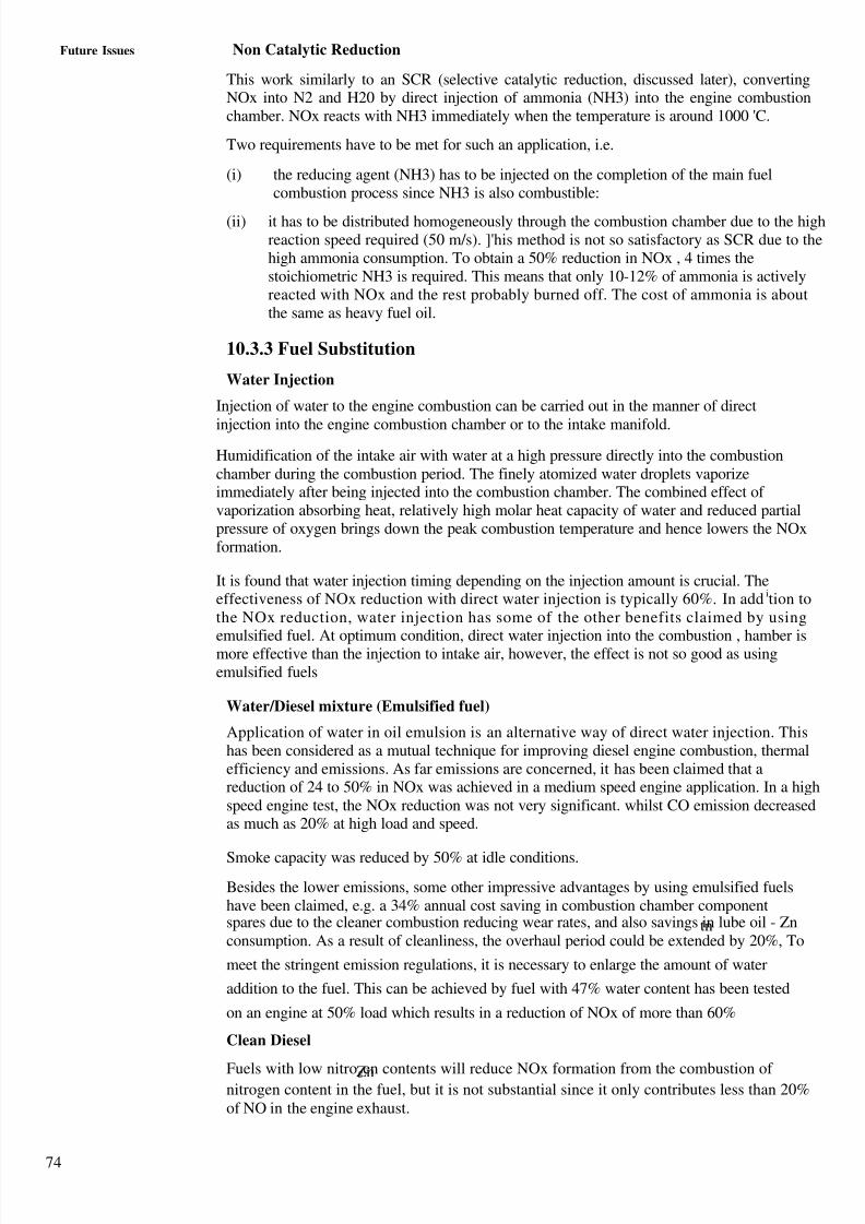
8/6/2019 IMU Future Issues
http://slidepdf.com/reader/full/imu-future-issues 73/123
74
Future Issues Non Catalytic Reduction
This work similarly to an SCR (selective catalytic reduction, discussed later), convertingNOx into N2 and H20 by direct injection of ammonia (NH3) into the engine combustionchamber. NOx reacts with NH3 immediately when the temperature is around 1000 'C.
Two requirements have to be met for such an application, i.e.
(i) the reducing agent (NH3) has to be injected on the completion of the main fuelcombustion process since NH3 is also combustible:
(ii) it has to be distributed homogeneously through the combustion chamber due to the highreaction speed required (50 m/s). ]'his method is not so satisfactory as SCR due to thehigh ammonia consumption. To obtain a 50% reduction in NOx , 4 times thestoichiometric NH3 is required. This means that only 10-12% of ammonia is activelyreacted with NOx and the rest probably burned off. The cost of ammonia is aboutthe same as heavy fuel oil.
10.3.3 Fuel Substitution
Water Injection
Injection of water to the engine combustion can be carried out in the manner of direct
injection into the engine combustion chamber or to the intake manifold.
Humidification of the intake air with water at a high pressure directly into the combustionchamber during the combustion period. The finely atomized water droplets vaporizeimmediately after being injected into the combustion chamber. The combined effect of vaporization absorbing heat, relatively high molar heat capacity of water and reduced partialpressure of oxygen brings down the peak combustion temperature and hence lowers the NOxformation.
It is found that water injection timing depending on the injection amount is crucial. Theeffectiveness of NOx reduction with direct water injection is typically 60%. In addition tothe NOx reduction, water injection has some of the other benefits claimed by using
emulsified fuel. At optimum condition, direct water injection into the combustion , hamber ismore effective than the injection to intake air, however, the effect is not so good as usingemulsified fuels
Water/Diesel mixture (Emulsified fuel)
Application of water in oil emulsion is an alternative way of direct water injection. Thishas been considered as a mutual technique for improving diesel engine combustion, thermalefficiency and emissions. As far emissions are concerned, it has been claimed that areduction of 24 to 50% in NOx was achieved in a medium speed engine application. In a highspeed engine test, the NOx reduction was not very significant. whilst CO emission decreasedas much as 20% at high load and speed.
Smoke capacity was reduced by 50% at idle conditions.
Besides the lower emissions, some other impressive advantages by using emulsified fuelshave been claimed, e.g. a 34% annual cost saving in combustion chamber componentspares due to the cleaner combustion reducing wear rates, and also savings in lube oil - Zntnconsumption. As a result of cleanliness, the overhaul period could be extended by 20%, To
meet the stringent emission regulations, it is necessary to enlarge the amount of water
addition to the fuel. This can be achieved by fuel with 47% water content has been tested
on an engine at 50% load which results in a reduction of NOx of more than 60%
Clean Diesel
Fuels with low nitrogen contents will reduce NOx formation from the combustion of Znnitrogen content in the fuel, but it is not substantial since it only contributes less than 20%of NO in the engine exhaust.
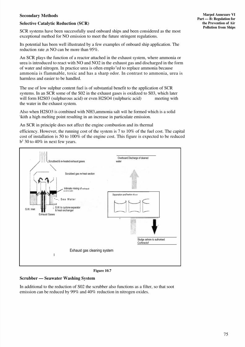
8/6/2019 IMU Future Issues
http://slidepdf.com/reader/full/imu-future-issues 74/123
75
Marpol Annexure VIPart — B: Regulation for
the Prevention of AirPollution from Ships
Secondary Methods
Selective Catalytic Reduction (SCR)
SCR systems have been successfully used onboard ships and been considered as the mostexceptional method for NO emission to meet the future stringent regulations.
Its potential has been well illustrated by a few examples of onboard ship application. Thereduction rate in NO can be more than 95%.
An SCR plays the function of a reactor attached in the exhaust system, where ammonia orurea is introduced to react with NO and NO2 in the exhaust gas and discharged in the formof water and nitrogen. In practice urea is often employed to replace ammonia becauseammonia is flammable, toxic and has a sharp odor. In contrast to ammonia, urea isharmless and easier to be handled.
The use of low sulphur content fuel is of substantial benefit to the application of SCRsystems. In an SCR some of the S02 in the exhaust gases is oxidized to S03, which laterwill form H2S03 (sulphurous acid) or even H2SO4 (sulphuric acid) meeting withthe water in the exhaust system.
Also when H2SO3 is combined with NH3,ammonia salt will he formed which is a solid \kith a high melting point resulting in an increase in particulate emission.
An SCR in principle does not affect the engine combustion and its thermal
efficiency. However, the running cost of the system is 7 to 10% of the fuel cost. The capitalcost of installation is 50 to 100% of the engine cost. This figure is expected to be reducedby 30 to 40% in next few years.
Figure 10.7
Scrubber — Seawater Washing System
In additional to the reduction of S02 the scrubber also functions as a filter, so that sootemission can be reduced by 99% and 40% reduction in nitrogen oxides.
Separation and f bwtion Rant
S.W. Inlet
Overboard Discharge of cleanedScrubbed & re-heated exhaust gases water
Scrubbed gas re-heat section
I Intimate mixing of exhaustpu and vs water
* — , S e a W a t e r
S.W. to cyclone separator & heat exchanger
Exhaust Gases
V
Sludge ashore to authorised
CoAtractof
Exhaust gas cleaning systemI
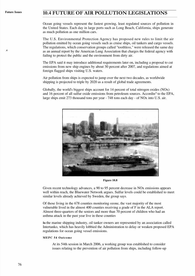
8/6/2019 IMU Future Issues
http://slidepdf.com/reader/full/imu-future-issues 75/123
76
Future Issues
4
10.4 FUTURE OF AIR POLLUTION LEGISLATIONS
Ocean going vessels represent the fastest growing, least regulated sources of pollution inthe United States. Each day in large ports such as Long Beach, California, ships generateas much pollution as one million cars.
The U.S. Environmental Protection Agency has proposed new rules to limit the airpollution emitted by ocean going vessels such as cruise ships, oil tankers and cargo vessels.
The regulations, which conservation groups called "toothless," were released the same dayas an annual report by the American Lung Association that charges the federal agency withfailing to protect the public and the environment from dirty air.
The EPA said it may introduce additional requirements later on, including a proposal to cutemissions from new ship engines by about 30 percent after 2007, and regulations aimed atforeign flagged ships visiting U.S. waters.
Air pollution from ships is expected to jump over the next two decades, as worldwideshipping is projected to triple by 2020 as a result of global trade agreements.
Globally, the world's biggest ships account for 14 percent of total nitrogen oxides (NOx)and 16 percent of all sulfur oxide emissions from petroleum sources. According to the EPA,
large ships emit 273 thousand tons per year - 748 tons each day - of NOx into U.S. air.
Figure 10.8
Given recent technology advances, a 90 to 95 percent decrease in NOx emissions appears
well within reach, the Bluewater Network argues. Sulfur levels could be established to meetsimilar levels already achieved by Sweden, the group says.
Of those living in the 678 counties monitoring ozone, the vast majority of the mostvulnerable lived in the almost 400 counties receiving a grade of F in the ALA report.Almost three-quarters of the seniors and more than 70 percent of children who had anasthma attack in the past year live in these counties
In the marine shipping industry, oil tanker owners are represented by an association calledIntertanko, which has heavily lobbied the Administration to delay or weaken proposed EPAregulations for ocean going vessel emissions.
MEPC 54 Outcome
At its 54th session in March 2006, a working group was established to considerissues relating to the prevention of air pollution from ships, including follow-up

8/6/2019 IMU Future Issues
http://slidepdf.com/reader/full/imu-future-issues 76/123
77
Marpol Ann \ IePar t –B: Regulat ions for
the Prevention of fir
Pollution from Ships
action to the IMO Policies and practices related to the reduction of greenhouse gas
emissions from ships (resolution A.963(23)).
Following the work by the group, the MEPC approved t wo circulars aimed at
assisting implementation of MARPOL Annex VI:1.
The MEPC Circular on Bunker Definer, Note and Fuel Oil Sampling, to
clarify how to comply with regulation 18, which places requirements on ship
owners and fuel oil suppliers in respect of bunker delivery notes and
representative samples of the fuel oil received and on P arties to the 1997
Protocol to regulate the bunker suppliers in their ports. The circular urg es allZ~
Member States, both Parties and non-Parties to the 1997 Protocol, to require
fuel oil suppliers in their ports to comply with the requirements and to raise
awareness of the necessity to enhance implementation and enforcement of
regulation 18 of Annex VI.
The MEPC circular on Notification to the Organization on ports or terminals
where volatile organic compounds (VOCs) emissions are to be regulated,
which notes that reg ulation 15 of Annex VI requires Parties to inform the
Organization of their intention to introduce requirements for the use of vapour
emission control sy stems and to notify the Org anization of ports and terminals
under the ir jurisdict ion where such requirements are a lready in force .However many terminals ace implementing or operating such practices
Without notification to the oorganization.The Commit tee shared the concern that. ,since
there is no circulation of such information, it is difficult for owners and operators to
prepare for these changes at ports and terminals.
The circular reiterates that Parties to the 1997 Protocol are required to notify them Organization
without delay with information oil ports and terminals und,_r their jurisdiction at which
VOCs emissions are or will be regulated, and on requirements imposed oil ships calling
at these ports and terminals. Any information received by the Organization on the
availability of vapour emission control systems will be circulated through MEPC
circu lars so that owners and operators will have up t o-date information on current and
future requirements for the utilization of such systems.
As instructed by MEPC 53, the Sub-Committee on Bulk Liquids and Gases (BIB .G)
will undertake a review of MARPOL Annex VI and the NOx Technical Code with a
view to revising the regulations to take account of current technology and the need to
further reduce air pollution from ships. The prog ress of this work will be reported to
the next session of the MEPC.
The Committee and its Working Group on Air Pollution had long and extensive
debates on how to follow UP resolution A.963(23) on IMO Policies and Practices
related to the Reduction of Greenhouse Gas Emissions from Ships. By the
resolution. the Assembly urged MEPC to identify and develop the necessary
mechanisms needed to achieve the l imitation or reduction of GHG emissions from
international shipping . Among the items considered was whether only emission of
CO2 or of all six greenhouse gases identified by the Kyoto Protocol should be
included.
The MEPC agreed to consider the follow-up actions to resolution A.963(23) in a
technical and methodological perspective and to c oncentrate the work on CO2
emissions. The Committee also agreed to continue the work at the next session and,Z:'
in particular, to consider further a draft work plan to identify and develop the
mechanisms needed to achieve the goal set by the Assembly.
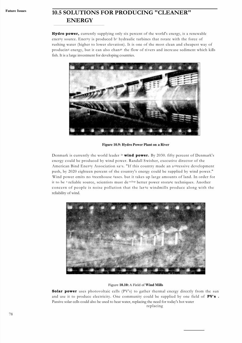
8/6/2019 IMU Future Issues
http://slidepdf.com/reader/full/imu-future-issues 77/123
uture Issues 10.5 SOLUTIONS FOR PRODUCING "CLEANER"
ENERGY
Hydro power, currently supplying only six percent of the world's energy, is a renewable
energ y source. Energ y is produced by hydraulic turbines that rotate with the force of
rushing water (higher to lower elevation). It is one of the most clean and cheapest way of
producin g energy, but it can also change the flow of ri vers and incre ase sediment which kills
fish. It is a large investment for developing countries.
Figure 10.9: Hydro Power Plant on a River
Denmark is currently the world leader in wind power. By 2030. fifty percent of Denmark's
energy could be produced by wind power. Randall S wisher, executive director of the
American Bind Energ y Association sa y s. "If this country made an a gg ressive development
push, by 2020 eighteen percent of the country's energy could be supplied by wind power."
Wind power emits no g reenhouse g ases. but it takes up lar ge amounts of land. In order for
it to be a reliable source, scientists must de velop better power storag e techniques. Another
concern of people is noise pol lut ion that the lar g e windmil ls produce a long with the
reliability of wind.
Figure 10.10: A Field of Wind Mills
Solar power uses photovoltaic cells (PV's) to gather thermal energy directly from the sun
and use it to produce electricity. One community could be supplied by one field of PV's .
Passive solar cells could also be used to heat water, replacing the need for today's hot waterreplacing
78

8/6/2019 IMU Future Issues
http://slidepdf.com/reader/full/imu-future-issues 78/123
Marpol Annexiure V I
Part — B: Regulation for
the Prevention of AirPollution from Ships
heaters. PV's do not emit any greenhouse gases, but they are very expensive and more
development is needed in order for this to be realistic energy source for the future.
Figure 10.11 : A Field of PV's gathering sunlight to produce Power
Nuclear power is strong is Europe with about forty-two percent of their energy produced by
fission. Nuclear generations provides about 17% of world electricity, avoiding the emission
of up to ?.3 billion tonnes of carbon dioxide annually. France produces 76% and Lithuania
produces 85.6% of its energy by nuclear fission. People are antinuclear because of 3 Mile
Isle .d in 1979 and Chernobyl in 1986. However, many experts say that it is a safe, clean,
and reliable source of energy. Nuclear Fission produces no greenhouse gases,but does produce highly toxic radioactive wastes.
I C_ -
Figure 111.12: Nuclear power plants have had success in Europebut not in the United States
S AQ 1
(a) How is Sox pollution controlled:
(i) Outside emission control area
(ii) Inside emission control area?
(h) What are Volatile Organic compounds? How do they cause pollution'?
(c) Why are reception facilities required?
(d) What is an incinerator?
(e) Incineration of which all substances is prohibited?
(t) Which all qualities should Fuel oils possess? 79
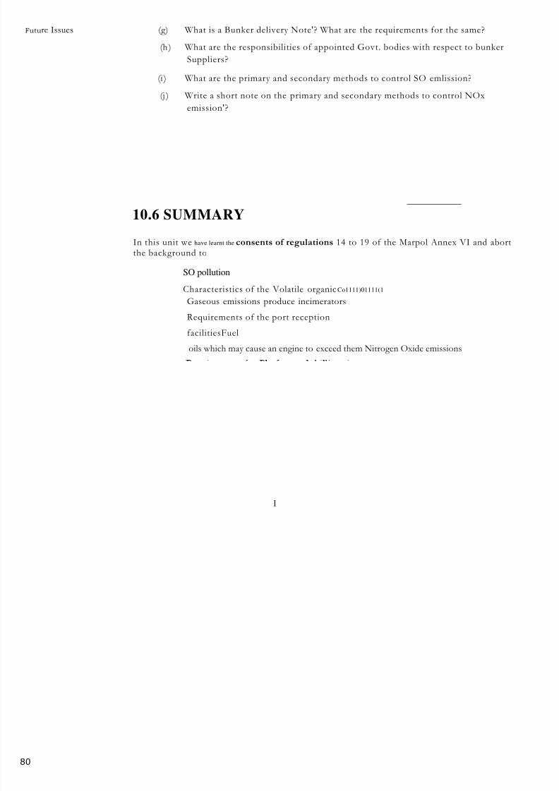
8/6/2019 IMU Future Issues
http://slidepdf.com/reader/full/imu-future-issues 79/123
80
Future Issues (g) What is a Bunker delivery Note'? What are the requirements for the same?
(h) What are the responsibilities of appointed Govt. bodies with respect to bunker
Suppliers?
(i ) What are the primary and secondary methods to control SO emlission?
(j ) Write a short note on the primary and secondary methods to control NOx
emission'?
10.6 SUMMARY
In this unit we have learnt the consents of regulations 14 to 19 of the Marpol Annex VI and abortthe background to
SO pollution
Characteristics of the Volatile organic Co1111)01111(1
Gaseous emissions produce incimerators
Requirements of the port reception
facilitiesFuel
oils which may cause an engine to exceed them Nitrogen Oxide emissions
I

8/6/2019 IMU Future Issues
http://slidepdf.com/reader/full/imu-future-issues 80/123
81
UNIT 11 FUEL CONSERVATION
Structure
I1.1 Introduction
Objectives
11 .2 Overview of Energy Resources Worldwide.
1 13 Solar Energy
11.4 Wind Energy
11.5 Tidal Flnergy
1 1.6 Wave Energy
1 1.7 Hydropower Energy
11.8 Marine Current Energy
11.9 Factors Affecting Fuel Consumption o n Board Ships
11.10 New Innovations in Shipping towards Fuel Conservation
11 .11 Summary
11.1 INTRODUCTION
This module discusses Fuel conservation as an ur g ent need that must he addressed by all
forums. It also introduces unconventi onal means of energy such as Soar. Wind,
Tidal, Hydropower and Marine Current energy.
The Inevitable Increase in Energy Consumption
It is easy to predict that world energy demand, and especially that for electricity, will increase
greatly during this 21st century, not only because of demographic pressures but also throu g h an
improvement in living standards in the less developed countrie s whi ch will represent 7
billion inhabitants in 2050 (78k of the total).
Consumption of primary energy will increase up to threefold by the middle of t hisZ7century, and the increase will be even grater for electricity . In view of this situation, many
Sources of energy will be necessary, but for environmental reasons, a high priority should
be the development of a ll technically feasible potential from clean r enewable sources,
especially hydropower.
Objectives
After studying this unit you should be able to
enumerate present status and future of the fossil fuels and• describe various alternative sources of energy and new innovation in shipping
towards fuel conservation:
11.2 OVERVIEW OF ENERGY RESOURCESWORLDWIDE
The main finding s of the 2001 Survey of Energy Resources produced by the World 0energ y Council confirms that conventional commercial fossil fuels, encompassing coal,
oil and natural gas, remain in adequate supply,-with a substantial resourcebase. gas
to the 1998 Survey, coal and natural gas reserves increased somewhat, while
those of oil declined slightly for following reasons:
proved recoverable reserves of oil, which are largely concentrated in the Middle
East, declined, while those of gas, which are more evenly spread, increased;
8/6/2019 IMU Future Issues
http://slidepdf.com/reader/full/imu-future-issues 81/123
82
I mule kqw-,• fewer giant fields were discovered i n the 1990's than in the 1960's (albeit a
larger proportion were in deeper offshore waters);
the discoveries of new oil fields were concentrated in a smaller number of
countries in the 1990's than in the earlier periods;
• more recently the additional discoveries have been less than the oil produced;
the oil industry's technological challeng es posed by the ultra-deep offshore have
not yet been met satisfactorily.
The e finding s of the 2001 survey are confined to reserve assessments and some of the
suppl aspects, and does not discuss oil demand. Thus the implications of environmentalconcerns, such as climate change, on the supply and demand for oil have not been
addressed. This may imply a more optimistic outlook for future oil demand growth. given a
growing world population and rising energ y demand, despite a possible tig htening of
Y
environmental laws.
Natural gas, on the other hand, confidently appears as a cleaner fossil fuel set to play ag reater role in satisfying energy demand. Encoura g ed by th e recent steady
increase in g as production and demand in the Asia Pacific region, (particularly in China)
and also in Africa, as well as by the prospect of market incentives promoted by the Clean
Development Mechanism, it is assumed that the current increase in demand for natural gas
is an indication of a long -term trend. Advanced technologies such as combined-cyclepower plants, acid gas re-injection, hydrogen fuel cells, etc. could expand the frontiers of
both natural gas demand and supply.
Despite the high predictability of Tidal energy's resource and timing, long construct ion
times, high capital intensity and low load factors are likely to make switching over to this
form of energy a costly proposition.
Scotland, Australia, Denmark and the USA, have a high potential for wave energy supply
− it could provide 10% of the current world electricity supply (if appropriately harnessed)
− and the potential synergies with the offshore oil and g as industry. However, a number of
necessary technologica l improvements are s t i l l required and ful l ut i l isat ion of wave
energy potential appears to be some way off.
It is acknowledg ed that there has been little research into utilising Marine current energy
for power generation and today no commercial turbines are in operation (thus making the
assessment of production costs difficult). There is, however, a large global marine current
resource potential which possesses a number of advantages over other renewables, such
as its higher energy density, highly predictable power outputs, independence from
extreme atmospheric fluctuations and a zero or minimal visual impact.
It is expected that Uranium will remain in ample supply over the next decade despite an
81/( decline between 1 January 1997 and 1 January 1999 in known world uranium
resources. From 1991 through 1999 over 40% of the total world uranium requirementsZ~
were met from non-mine supplies, more than half of which came from the Russian
Federation's stockpiles. Another important supply
source has been from dismantlednuclear weaponry.
On the Nuclear power generat ion s ide , i t is reported that there has been a v irtual
stag nation in the number of nuclear power plants in North America and Western Europe. a
slow growth in Eastern Europe and an expansion in East Asia. Both the International
Energy Ag ency (IEA) and the International Atomic Ener g y Agency (IAEA) expect that in
the coming two decades the current and new additions in Asia and in countries with
economics in transition would roughly balance those being retired. Major recent
developments include the significant economic advantag e of fully depreciated nuclear
power plants, which encourages life extension programmes in liberalised power markets
such as the US: moves towards earlier closures of nuclear power plants h\ anti-nuclear
g overnments in Europe, the shorter construction periods and low er Operating Co s ts of recentstandardised plants, as in France. Japan and the Republic of Korea; important
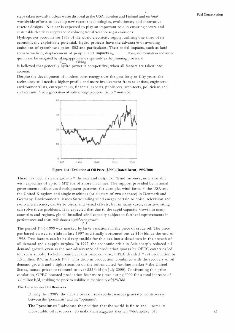
8/6/2019 IMU Future Issues
http://slidepdf.com/reader/full/imu-future-issues 82/123
Fuel Conservationsteps taken towards nuclear waste disposal in the USA. Sweden and Finland and ong oing
worldwide efforts to develop new reactor technologies, evolutionary and innovative
reactor designs . Nuclear is expected to play an important role in ensuring secure and
sustainable electricity supply and in reducing g lobal g reenhouse gas emissions.
Hydropower accounts for 19% of the world electricity supply, utilising one third of its
economically exploitable potential. Hydro projects have the advanta g e of avoiding
emissions of greenhouse gases, S02 and particulates. Their social impacts, such as land
transformation, displacement of people. and impacts on flora, sedimentation and water
quality can be mitigated by taking appropriate steps early In the planning process. itZ__ taking
is believed that generally hydro power is competitive, when all factors are taken into
account.
Despite the development of modern solar energy over the past forty or fifty years, the
technolog y still needs a higher profile and more involvement from scientists, engineers.
environmentalists, entrepreneurs, financial experts, publishers, architects, politicians and
civil servants. A new generation of solar-energy pioneers has to be nurtured.
Figure 11.1: Evolution of Oil Price ($/bbl) (Dated Brent) 1997/2001
There has been a steady growth in the size and output of Wind turbines, now available
with capacities of up to 3 MW for offshore machines. The support provided by national
governments influences development patterns: for example, wind farms in the USA and
the United Kingdom and single machines (or clusters of two or three) in Denmark and
Germany. Environmental issues Surrounding wind energy pertain to noise, television and
radio interference, dang er to birds, and visual effects, but in many cases, sensitive siting
can solve these problems. It is expected that due to the sapid capaci ty g rowth in many
countries and regions. global installed wind capacity subject to further i mprovements in
performance and costs, will show a significant growth.Z:1
The period 1996-1999 was marked by larg e variations in the price of crude oil. The price
per barrel started to slide in late 1997 and finally bottomed out at $10/bbl at the end of 1998. Two factors can be held responsible for this decline: a slowdown in the g rowth of
oil demand and a supply surplus. In 1997, the economic crisis in Asia sharply reduced oil
demand growth even as the non-observance of production quotas by OPEC countries led
to excess supply. To help counteract this price collapse, OPEC decided to cut production by
1.5 million B/d in March 1999. This drop in production, combined with the recovery of oil
demand growth and a tight situation on the reformulated g asoline market in the United
States, caused prices to rebound to over $35/bbl (in July 2000). Confronting this price
escalation, OPEC boosted production four more times during 2000 for a total increase of
3.7 million b/d, enabling the price to stabilise in the vicinity of $25/bbl.
The Debate over Oil Reserves
During the 1990's. the debate over oil reserveshresources generated controversy
between the "pessimists" and the "optimists".
The "pessimists" advocate the position that the world is finite and some its
recoverable oil resources. To make their ar pl cargument. they rely on descripitiveC~ - 83
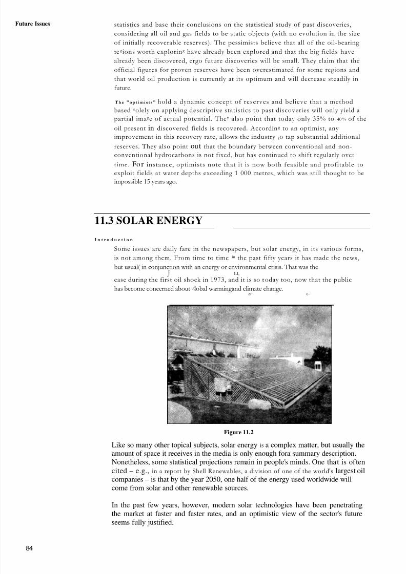
8/6/2019 IMU Future Issues
http://slidepdf.com/reader/full/imu-future-issues 83/123
84
Future Issues statistics and base their conclusions on the statistical study of past discoveries,
considering all oil and gas fields to be static objects (with no evolution in the size
of initially recoverable reserves). The pessimists believe that all of the oil-bearing
re g ions worth exploring have already been explored and that the big fields have
already been discovered, ergo future discoveries will be small. They claim that the
official figures for proven reserves have been overestimated for some regions and
that world oil production is currently at its optimum and will decrease steadily in
future.
The "opt imis ts" hold a dynamic concept of reserves and believe that a methodbased solely on applying descriptive statistics to past discoveries will only yield a
partial imag e of actual potential. They also point that today only 35% to 40 % of the
oil present in discovered fields is recovered. According to an optimist, any
improvement in this recovery rate, allows the industry to tap substantial additional
reserves. They also point out that the boundary between conventional and non-
conventional hydrocarbons is not fixed, but has continued to shift regularly over
time. Fo r instance, optimists note that it is now both feasible and profitable to
exploit fields at water depths exceeding 1 000 metres, which was still thought to be
impossible 15 years ago.
11.3 SOLAR ENERGY
I n t r o d u c t i o n
Some issues are daily fare in the newspapers, but solar energy, in its various forms,
is not among them. From time to time in the past fifty years it has made the news,
but usual( in conjunction with an energy or environmental crisis. That was the J LI,
case during the first oil shock in 1973, and it is so t oday too, now that the public
has become concerned about g lobal warmingand climate change.Z7 C~
Figure 11.2
Like so many other topical subjects, solar energy is a complex matter, but usually theamount of space it receives in the media is only enough fora summary description.Nonetheless, some statistical projections remain in people's minds. One that is oftencited – e.g., in a report by Shell Renewables, a division of one of the world's largest oilcompanies – is that by the year 2050, one half of the energy used worldwide willcome from solar and other renewable sources.
In the past few years, however, modern solar technologies have been penetratingthe market at faster and faster rates, and an optimistic view of the sector's futureseems fully justified.
8/6/2019 IMU Future Issues
http://slidepdf.com/reader/full/imu-future-issues 84/123
Fuel ConservationA Technologically Advanced World
Until the discovery of fossil fuels and the beginning of the industrial revolution, thesun's energy — in its different forms, direct and indirect (such as wind and biomass)— was the sole energy source that inspired and enabled the development of humansocieties. Since then, and especially in the past one hundred years - a relativelyshort span of time - a powerful energy infrastructure that now covers practically theentire planet and is based on fossil fuels and nuclear energy has been built. Todaythe world consumes 9 billion tons per year, compared with around 500 million tons in1860. While these energy uses and infrastructure do not yet benefit billions of poor
people who still try to make do with firewood, they give humanity a power overnature that earlier generations never knew; they had to survive with the renewableenergy of the sun.
Figure 11.3
This power helps us live more comfortably than past generations, but while itmeets new needs, it also carries the risk of irreversibly altering natural balances,
both local and global.
The world's population has been growing rapidly over the last century andcontinues to grow. We were 1.6 billion in 1900; we have now passed the 6 billionmark. If this trend continues, the human population will rise to about 9 billion by2050. The increasingly crowded world has also become a world of cities. Fiftypercent of the population already lives in cities and the figure is expected to rise to75% by the year 2050. Dozens of cities already number more than 10 millionpeople.
Solar Energy, Past and Future
With the exception of nuclear, geothermal and tidal energy, all forms of energy used on
earth originate from the sun's energy.
Some are renewable, some are not. Renewable is the term used for forms of energy thatcan be regenerated, or renewed, in a relatively short amount of time. The regenerationprocess may be continuous and immediate, as in the case of direct solar radiation, or itmay take some hours, months or years. This is the case of wind energy (generated by theuneven heating of air masses), hydro energy (related to the sun-powered cycle of waterevaporation and rain), biomass energy (stored in plants through photosynthesis), and theenergy contained in marine currents.
The flow of renewable solar energies on earth is essentially equal to the flow of energydue to solar radiation. Every year, the sun irradiates the earth's land masses with theequivalent of 19 trillion tons. A fraction of this energy could satisfy the world's energy
requirements, around 9 billion tons per year.
For thousands of years, the sun's renewable energy was humanity's sole source of energy.Its role started to decrease only a few centuries ago, with the progress of 85

8/6/2019 IMU Future Issues
http://slidepdf.com/reader/full/imu-future-issues 85/123
86
Future Issues industrialisation. the diffusion of new technologies, and the discovery of new fossil fuels(coal has been used since ancient times) and eventually nuclear power.Today solar sources provide around 10% of the energy used worldwide, but in thedeveloping countries their share is still of the order of 40%. This contribution could startgrowing again, thanks to progress in solar technology and the pressure of recurrent energy
4:1 again, technolog
environmental erises related to fossil fuels and nuclear power.
To raise the contribution to 50% of world energy use by 2050, as suggested in the ShellRenewables report, would require sweeping changes in our energy infrastructure. These
A,
changes can be achieved only through the parallel development of a new, morechange way of thinking about our environment and how we generate and useenergy: a new culture that should pervade every part of society and shape theresponsibilities of each.
Current Solar Technologies
Solar technologies – some primitive, some more advanced – have been used in all agesand in every corner of the world, but the invention and development of modern solartechnologies goes back only forty or fifty years. By now the world has seen numerouspractical demonstrations that sophisticated solar-powered facilities can be built andoperated successfully as part of energy systems ranging from the scale of an individualhome, to a large industrial or commercial complex, or even a whole city or rural area.
As early as the 1980's, a 354-MW solar power plant was built in the Mojave Desert, inCalifornia. Here the heat contained in solar rays, concentrated by reflecting troughs andraised to 400°C, produces steam that runs a conventional power generator. When the sun isnot shining, the plant switches to natural gas. The latest generation of this type of plantincorporates new engineering solutions and new scientific principles such as non-imagingoptics, which makes it possible to build much more efficient concentrators at lower costs.These developments open new prospects for the technology in the sunniest parts of the
C7world.
A solar technology that has already had a great impact on our lives is photovoltaics. Not interms of the amount of electricity it produces (in 1999 only 200 MW were installed), but
because of the fact that photovoltaic cells – workin
g
silently, not pollutin
g
– can generateelectricity wherever the sun shines, even in places where no other form of electricity can beobtained.
For instance, photovoltaic cells generate the power that runs space satellites. Withouttelecommunications satellites, many of our now-routine activities – from watchinginternationally broadcast entertainment to using cell phones – would still be in the realm of science fiction. And space exploration and research too might still be science fiction.
On earth, photovoltaic technology is used to produce electricity in areas where power linesdo not reach. In the developing countries, it is significantly improving living conditions inrural areas. Thanks to its flexibility, it can be incorporated in packages of ener gy servicesand thus offer unique opportunities to improve rural health care, education,
communication, agriculture, lighting and water supply.
The use of energy in the form of heat is one of the largest items in the energy budget. In t,Europe, for instance, it accounts for around 50% of total energy consumption: around 630million tons, of which 383 in low-temperature heat and 247 in medium- and high-temperature heat.
Today, low-temperature (<100°C) thermal solar technologies are reliable and mature forthe market. Worldwide, they help to meet heating needs with the installation of severalmillion square metres of solar collectors per year.
These technologies can play a very important role in advanced energy-saving projects,especially in new buildings and structures that require large amounts of hot water, heating
and cooling.

8/6/2019 IMU Future Issues
http://slidepdf.com/reader/full/imu-future-issues 86/123
ue ct; conservatio
1.4 WIND ENERGYor w n energy
capacity has been doubling every three years during the last decadetwoyears have been even faster, as shown in Figure 13.1. It and growth
r a t e s in the F i g u r e i s doubtful whether any other energy technology is growing, or hasgrown, at such a rate.
wind capacity at the end of 2000 was around 17 5 MW and generationT o t a l world PQannual consumption of electricity in wind now approximately with but Denmark, with
_ _ " P ' 1 1P"
Singapore. Germany, with over 6 000 MW, has the highest ";k
over 2 000 MW, has t he highest level per capita and the production accounts ik), -112% of Danish electricity.
Figure 11.4
Figure 11.5: Growth of World Wind Capacity
The attractions of wind as a source of electricity which produces minimal quantities of
greenhouse gases has led to ambitious targets for wind energy in many parts o f the world.
More recently, there have been several developments of offshore wind installations and
many more are planned. Although offshore wind-generated electricity is generally more
expensive than onshore, the resource is very large and there are few environmentallarg
Whilst wind energy is generally developed in the industrialised world for environmentalenergit has attractions in the developing world as it can be installed quickly in areas C,
where electricity is urgently needed. In many instances it may be a cost-effective solution
if fossil fuel sources are not readily available. In addition there are many applications for
'hind d capacity, MOM
Is
15,0 T)
10.00D
5,00-1
n #_ 4 4 4 1 1 1 1
1996 1992 2iXIOYear
87

8/6/2019 IMU Future Issues
http://slidepdf.com/reader/full/imu-future-issues 87/123
Future Issues wind energy in remote regions, worldwide, either for supplementing diesel power (which I
a and other installations on an tends tobe expensive) or for supplying farms, homes and
individual basis.
11.5 TIDAL ENERGY
The tide moves a huge amount of water twice each day , and harnessing it could provide agreat deal of energy - around 20% of Britain's Leeds th ou gh t he en er gy s up pl y i sreliable and plentiful, converting it into useful electrical power is not easy. There are
_:o L_eight
main sites around Britain where tidal power stations could usefully be built, including theSevern, Dee, Solway and Humber estuaries. Only around 20 sites in the world havebeep identified as possible tidal power stations. These work rather like a hydro-electricscheme, except that the dam is much bigger.
A huge dam (called a "barrage") is built across a river estuary. When the tide goes in andout, the water flows through tunnels in the dam. The ebb and flow of the tides can beused to turn a turbine or it can be used to push air through a pipe, which then turns a turbine.Large lock gates, like the ones used on canals allow ships to pass.
If one was built across the Severn Estuary, the tides at Weston-super-Mare would not goout nearly as far - there'd be water to play in for most of the time.
But the Severn Estuary carries sewage and other wastes from many places (e.g. Bristol &L,
Gloucester) out to sea. A tidal barrage would mean that this stuff would hang around Weston-super-Mare an awful lot longer! Also, if you're a wading bird that feeds on theexposed mud flats when the tide goes out, then you have a problem, because the tide won't be going out properly any more
Tu rb ine F genera tor
Figure 11.6
• .Advantages of Tidal energy
Once you've built it, tidal power is free.
• It produces no greenhouse gases or other waste.
• It needs no fuel.
It produces electricity reliably.
\()I expensive to maintain.
• I ides are totally predictable.

8/6/2019 IMU Future Issues
http://slidepdf.com/reader/full/imu-future-issues 88/123
conservationDisadvantages of Tidal energy
barrage across an estuary is very expensive to build, and affects a very wide area
the environment is changed for many miles upstream and downstream. Many i rd
rely on the tide uncovering the mud flats so that they can feed. There are few suitable
sites for tidal barrages:L~
only provides power for around 10 hours each day, when the tide is actually
moving in or out.
oceans of the rotating
earth. The relative motions of these bodies cause the surface of theoceans to be raised and lowered periodically, according to a number or interacting cycles.
These include:
I A half day cycle, due to the rotation of the earth within the gravitational field of the
moon
• 14 day cycle, resulting from the gravitational field of the moon combining with
that of the sun to give alternating spring (maximum and neap (minimum) tides
• A half year cycle, due to the inclination of the moon's orbit to that of the earth,giving rise to maxima in the spring tides in March and SeptemberThe
range of a spring tide is commonly about twice that of a neap tide, whereas the longer
period cycles impose smaller perturbations. In the open ocean, the maximum amplitude of
the tides is about one metre.. Tidal amplitudes are increased substantially towards the coast,
particularly in estuaries. This is mainly caused by shelving of the sea bed and funnelling of
the water by estuaries. In some cases the tidal range can be further amplified by reflection of
the tidal wave by the coastline or resonance. 'This is a special effect that Occurs in long,
trumpet sh aped estuaries, when the length of the estuary is close to one quarter of the tidal
wave length. 'These effects combine to give a mean spring tidal range of over I I m in the
Severn Estuary (UK). Asa result of these various factors, the tidal range can vary
substantially between different points on a coastline.
The amount of energy obtainable from a tidal energy scheme therefore varies with
location an d time. Output changes as the tide ebbs and floods each day; it can also vary
by a factor of about four over a spring-neap cycle. Tidal energy is, however, highlypredictable in both amount and timing.
The available energy is approximately proportional to the square of the tidal range.
Extraction of energy from the tides is considered to be practical only at those sites where
the energy is concentrated in the form of large tides and the geography provides suitable
sites for tidal plant construction. Such sites are not commonplace but a considerable
• number have been identified in the UK, France, eastern Canada, the Pacific coast of
Russia, Korea, China. Mexico and Chile. Other sites have been identified along the
Patagonian coast of Argentina, Western Australia and western India.
11.6 WAVE ENERGY
Ocean waves are caused by the wind as it blows across the sea. Waves are a pow erfu I
source of energy. The problem is that it's not easy to harness this energy and convert it
into electricity in large amounts. Thus, wave power stations are rare. There are several
methods of getting energy from waves, but one of the most effective works like a
swimming pool wave machine in reverse.
At a swimming pool, air is blown in and out of a chamber beside the pool, which makes
the water outside bob up and down, causing waves. At a wave power station, the waves
arriving cause the water in the chamber to rise and fall, which means that air is forced in
and out of the hole in the top of the chamber.
We place a turbine in this hole, which is turned by the air rushing in and out. The turbine
turns a generator. A problem with this design is that the rushing air can be very noisy,
unless a silencer is fitted to the turbine. The noise is not a huge problem anyway, as the
waves make quite a bit of noise themselves.
~u
8 9
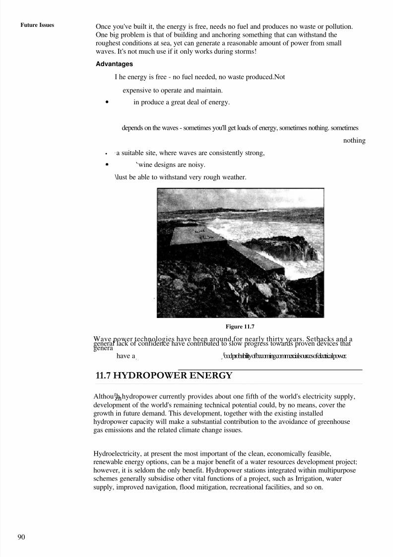
8/6/2019 IMU Future Issues
http://slidepdf.com/reader/full/imu-future-issues 89/123
90
Future Issues Once you've built it, the energy is free, needs no fuel and produces no waste or pollution.One big problem is that of building and anchoring something that can withstand theroughest conditions at sea, yet can generate a reasonable amount of power from smallwaves. It's not much use if it only works during storms!
Advantages
I he energy is free - no fuel needed, no waste produced.Not
expensive to operate and maintain.
• in produce a great deal of energy.
depends on the waves - sometimes you'll get loads of energy, sometimes nothing. sometimes
nothing
• ' a suitable site, where waves are consistently strong,
• ',wine designs are noisy.
\lust be able to withstand very rough weather.
Figure 11.7
Wave power technologies have been around for nearly thirty years. Setbacks and ageneral lack of confidence have contributed to slow progress towards proven devices thatgenera
have a good probability of becoming commercial sources of electrical power.t , Z--
11.7 HYDROPOWER ENERGY
Although hydropower currently provides about one fifth of the world's electricity supply,zndevelopment of the world's remaining technical potential could, by no means, cover thegrowth in future demand. This development, together with the existing installedhydropower capacity will make a substantial contribution to the avoidance of greenhousegas emissions and the related climate change issues.
Hydroelectricity, at present the most important of the clean, economically feasible,renewable energy options, can be a major benefit of a water resources development project;however, it is seldom the only benefit. Hydropower stations integrated within multipurposeschemes generally subsidise other vital functions of a project, such as Irrigation, water
supply, improved navigation, flood mitigation, recreational facilities, and so on.

8/6/2019 IMU Future Issues
http://slidepdf.com/reader/full/imu-future-issues 90/12391
Fuel Conservation
cean aMiddle East. " a
1 9 %,h
k
Id
North America
9i xiihAnteric1F.4%
Asia2F:
hgtwie 11.9
H o w I t W o r k s ?A dam is built to trap water; usually in a valley where there is an existing lake. Water is
allowed to How through tunnels in the dam, to turn turbine, and thus drive generators. Thedam is much thicker at the bottom than at the top, because the pressure of the waterincreases with depth.
Hydro-electric poWer stations can produce a great deal of power very cheaply.
When it was first built, the river,"HooverDam",ontheColoradover,suppliedmuchof L_
the electricity for the city of Las Vegas; however now Las Vegas has grown so much, thecity gets most of its energy from other sources
C',
Figure 11.9
Gravivional potential energy is stored in the water above the dam. Because of the greatheight of the water, it will arrive at the turbine at high pressure, which means that we canextract a great deal of energy from it. The water then flows away downriver as normal.
In mountainous countries such as Switzerland and New Zealand, hydro-electric powerprovides more than half of the country's energy needs.
An alternative is to build the station next to a fast-flowing river. However with thisarrangement the flow of the water cannot be controlled, and water cannot be stored forlater use.
&AdvantagesH y droffyd Toweris
virtually free.

8/6/2019 IMU Future Issues
http://slidepdf.com/reader/full/imu-future-issues 91/123
Futures Issues a Much more reliable than wind, solar or wave power.
Water can be stored above the dam ready to cope with peaks in demand.
a Hydro-electric power stations can increase to full power very quickly, unlike otherpower stations.
Electricity can be generated constantly
Disadvantages of Hydro-Power
The dams are very expensive to build. However, many dams are also used for floodcontrol or irrigation, so building costs can be shared.
building Building a large dam will flood a very large area upstream, causing problems for
I I
animals that used to live there.
a Finding a suitable site can be difficult - the impact on residents and theenvironment may be unacceptable.
Water quality and quantity downstream can be affected, which can have an impacton plant life.
C h a r a c t e r i s t i c s o f H y d r o p o w e r
The most important characteristics of hydropower can be summarised as follows:
It is a proven and well advanced technology, with more than a century of
experience. Modern power plants provide extremely efficient energy conversion;
It plays a major role in reducing greenhouse gas emissions in terms of avoidedgeneration by fossil fuels. Hydro is a relatively small source of atmospheric
emissions compared with fossil-fired generating options;C
It has the lowest operating costs and longest plant life, compared with other large-scale generating options. Once the initial investment has been made in the necessarycivil works, the plant life can be extended economically by relatively cheapmaintenance and periodic replacement of the electromechanical equipment;
As hydro plants are often integrated within multipurpose developments, theprojects can help to meet other fundamental human needs (for example, irrigation for
food supply, domestic and industrial water supply, flood protection). The reservoirwater may also be used for other functions such as fisheries, discharge regulationdownstream for navigation improvements, and recreation. Hydropower plants canhelp to finance these multipurpose benefits, as well as some environmentalimprovements in the area, such as the creation of wildlife habitats;
The 'fuel' (water) is renewable, and is not subject to fluctuations in marketconditions. Hydro can also represent energy independence for many countries.
11.8 MARINE CURRENT ENERGY
The global marine current energy resource is mostly driven by the tides and to a lesser extentby thermal and density effects. The tides cause water to flow inwards twice each day (floodtide) and seawards twice each day (ebb tide) with a period of approximately 12 hours and 24minutes (a semi-diurnal tide), or once both inwards and seawards in approximately 24 hoursand 48 minutes (a diurnal tide). In most locations the tides are a combination of the semi-diurnal and diurnal effects, with the tide being named after the most dominant type.
The strength of the currents varies, depending on the proximity of the moon and sun relativeto Earth. The magnitude of the tide-generating force is about 68% moon and 32% sun due totheir respective masses and distance from Earth. Where the semi-diurnal tide is dominant,the largest marine currents occur at new moon and full moon (spring tides) and the lowest atthe first and third quarters of the moon (neap tides). With diurnal tides, the current strength
varies with the declination of the moon (position of the moon relative to
92 the equator). The largest currents occur at the extreme declination of the moon and lowest

8/6/2019 IMU Future Issues
http://slidepdf.com/reader/full/imu-future-issues 92/123
93
Fuel Conservationcurrents at zero declination. Further differences occur due to changes between the distancesof the moon and sun from Earth, their relative positions with reference to Earth and varyingangles of declination. These occur with a periodicity of two weeks, one month, one year orlonger. and are entirely predictable.
Generally the marine current resource follows a sinusoidal curve with the largest currentsgenerated during the mid-tide. The ebb tide often has slightly larger currents than the floodtide. At the turn of the tide (slack tide), the marine currents stop and changedirection by approximately 180°.
The strength of the marine currents generated by the tide vary, depending on the position of a site on the earth, the shape of the coastline and the bathymetry (shape of the sea bed).Along straight coastlines and in the middle of deep oceans, the tidal range and marinecurrents are typically low. Generally, but not always, the strength of the currents isdirectly related to the tidal height of the location. However, in land-locked seas such asthe Mediterranean, where the tidal range is small, some sizeable marine currents exist.
There are some locations where the water flows continuously in one direction only, and thestrength is largely independent of the moon's phase. These currents are dependent on largethermal movements and run generally from the equator to cooler areas. The most obviousexample is the Gulf Stream, which moves approximately 80 million cubic metres of waterper second. Another example is the Strait of Gibraltar where in the upper layer, a constant
flow of water passes into the Mediterranean basin from the Atlantic (and a constantoutflow M the lower layer).
Areas that typically experience high marine current flows are in narrow straits, betweenislands and around headlands. Entrances to lochs, bays and large harbours often also havehigh marine current flows. Generally the resource is largest where the water depth isrelatively shallow and a good tidal range exists. In particular, large marine current flowsexist where there is a significant phase difference between the tides that flow on either sideof large islands.
There are many sites world-wide with velocities of 5 knots (2.5 m/s) and greater.Countries with an exceptionally high resource include the UK, Ireland, Italy, the
Philippines, Japan and parts of the United States.Status of Technology
Useful energy can be generated from marine currents using completely submerged turbinescomprising of rotor blades and a generator. Water turbines work on the same principle aswind turbines by using the kinetic energy of moving fluid and transferring it into usefulrotational and electrical energy. The velocities of the currents are lower than those of thewind, however owing to the higher density of water (835 times that of air) water turbinesare smaller than their wind counterparts for the same installed capacity.
The global marine current energy resource is very large, and it has a number of advantages over other renewables. Benefits of utilising marine current energy, including:
The resource has four times the energy density of. a goodwind site, so the diameter of water turbines can be less than half that of a windturbine for the same energy output;
The water velocities and therefore power outputs arecompletely predictable, once accurate site measurements have been taken;
• Water turbines will not need to be designed for extreme atmosphericfluctuations as required with wind turbines, meaning that the design can be bettercost-optimised,,
With increased conflicts over land use, water turbines offer asolution that will not occupy land and has minimal or zero visual impact;
•
The greatest resource is in close proximity to coastlines and many areas withhigh population densities;
The technology is potentially modular and avoidsthe need for large civil engineering works.
8/6/2019 IMU Future Issues
http://slidepdf.com/reader/full/imu-future-issues 93/123
94
Future Issues11.9 FACTORS AFFECTING FUEL CONSUMPTION
ON BOARD SHIPS
More than 150 billion tons of fuel oil is consumed on the seas per year. The value is morethan 30 billion USD. Approximately 15%, or more than 20 billion tons at a total value of approximately 3 billion USD are pure waste, resulting from traditionally accepted 'micro-fouling'. Billions of dollars more in fuel are wasted due to limited treatment of hulls indrydock, resulting in higher fuel consumption that lives with the ship over the course of a
drydock period. The reason is that marine growth starts at the same moment the ship'shull touches the water. In the beginning, no fouling can be seen, however, after some timethe submerged surfaces appear to be a bit slimy, when touched. Not alarming, in any way,but the resistance `micro-fouling' of the hull against propulsion is increased by up to10%. Later, a transparent green tinge seems to spread over large parts of the hull. Stillnot alarming, however, the hydrodynamic resistance is now increased by up to 20%.
When algae, seaweed, and barnacles start to adhere to the hull, it is easy to understand andtraditionally accepted that the performance has diminished greatly and that it is time forsome action. The increase in resistance at this stage may exceed 50%. A scrubbing of ahull in this described condition by divers will most probably damage, or even destroy, theanti fouling coating, and then fuel consumption (or reduced speeds at same fuel
consumption) will worsen in a short time frame. Dry-docking at this stage is of coursepossible, however, this means extra costs and loss of hire. So very often, the ship will justcontinue operation at lower and lower speed, creating losses as described above. The firsttwo stages of slime and growth alone penalize a tanker by a few tenths of a knot, undetectedby traditional analysis of noon data, yet can be cleaned without damaging the coating (percoating manufacturer's guidelines). Furthermore, it is common to find tankers that have lost1.0 to 1.5 knots as they approach a 5-year dry-dock.
During the construction period of a ship, naval architects and marine engineers expendeffort to optimize the hull form, the propeller shape, and the mechanical propulsion unitwhere every single percent of power loss counts. At the delivery of the ship, the
performance is carefully tested, and penalties paid, if the maximum speed does not reachthe promised parameters. Unfortunately, when the ship has been in service for some time,there have been no practical methods of evaluating precise performance losses due solely tofouling and then benchmarked against sea trials (clean, smooth hull).
11.10 NEW INNOVATIONS IN SHIPPING TOWARDSFUEL CONSERVATION
Rising fuel price trends, concern over climate change and the need to meet regulatoryrequirements all focus renewed priorities on the conservation of energy. Fuelconservation may be achieved by efficient operational methods as well as by innovative
technology as follows.SkyBails of Germany are developing an international patent pending propulsion system,harnessing the power of wind. World trade relies on cargo vessels to transport goodaround the globe with 98.2% of all intercontinental goods carried via sea, and 98% of allcargo vessels powered by diesel engines. All this equates to the fact that 25 billion Eurosworth of fuel was bought in the year 2002 alone.
The innovative SkySails system saves a considerable amount of fuel over long voyages,therefore cutting costs and helping the environment. The Skysails system consists of alarge towing kite filled with compressed air, and an autopilot and wind-optimised routemanagement system. The features of the SkySails technology enable ships to use windpower with entirely novel performance characteristics.
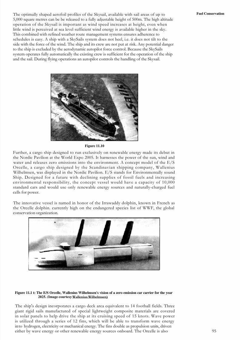
8/6/2019 IMU Future Issues
http://slidepdf.com/reader/full/imu-future-issues 94/123
Figure 11.1 t: The E/S Orcelle, Wallenius Wilhelmsen's vision of a zero emission car carrier for the year
2025. (Image courtesy Wallenius Wilhelmsen)
The ship's design incorporates a cargo deck area equivalent to 14 football fields. Threegiant rigid sails manufactured of special lightweight composite materials are coveredin solar panels to help drive the ship at its cruising speed of 15 knots. Wave poweris utilized through a series of 12 fins, which will be able to transform wave energy into hydrogen, electricity or mechanical energy. The fins double as propulsion units, driveneither by wave energy or other renewable energy sources onboard. The Orcelle is also 95
Fuel Conservation The optimally shaped aerofoil profiles of the Skysail, available with sail areas of up to5,000 square metres can be be released to a fully adjustable height of 500m. The high altitudeoperation of the Skysail is important as wind speed increases at height, even whenlittle wind is perceived at sea level sufficient wind energy is available higher in the sky. This combined with refined weather route management systems ensures adherence toschedules is easy. A ship with a SkySails system does not heel, i.e. it does not tilt to theside with the force of the wind. The ship and its crew are not put at risk. Any potential dangerto the ship is excluded by the aerodynamic autopilot force control. Because the SkySailssystem operates fully automatically the existing crew is sufficient for the operation of the ship
and the sail. During flying operations an autopilot controls the handling of the Skysail.
Figure 11.10
Further, a cargo ship designed to run exclusively on renewable energy made its debut inthe Nordic Pavilion at the World Expo 2005. It harnesses the power of the sun, wind and water and releases zero emissions into the environment. A concept model of the E/SOrcelle, a cargo ship designed by the Scandinavian shipping company, Wallenius Wilhelmsen, was displayed in the Nordic Pavilion. E/S stands for Environmentally sound
Ship. Designed for a future with declining supplies of fossil fuels and increasing environmental responsibility, the concept vessel would have a capacity of 10,000standard cars and would use only renewable energy sources and naturally-charged fuelcells for power.
The innovative vessel is named in honor of the Irrawaddy dolphin, known in French asthe Orcelle dolphin. currently high on the endangered species list of WWF, the globalconservation organization.

8/6/2019 IMU Future Issues
http://slidepdf.com/reader/full/imu-future-issues 95/123
96
Future Issues powered by two variable-speed electric propulsion systems known as pods. Thispropulsion system eliminates the traditional stern propeller and rudder arrangement.Around half the energy on the E/S Orcelle will be produced by fuel cells, - a rapidly
9 1developing new technology. These cells will combine hydrogen and oxygen to generatethe electricity which will be used in the pod propulsion systems and the fins, while alsoproducing electricity for other uses onboard. The only by-products from this process arewater vapor and heat.The ship's hull is a pentamaran, a new design concept in trans-ocean shipping. The design
consists of a wave-piercing slender hull fitted with four outriggers for added stability inheavy seas.
Cargo carrying capacity has been optimized, so that the Orcelle could carr y approximately10,000 cars - around 50 percent more than today's car carriers - while having a similarweight in tonnage terms. This increased level of efficiency has been achieved through theuse of lightweight materials, including aluminium and thermoplastic composites, and alsoby eliminating the need for ballast water tanks.
SAQ 1
(a) World Energy council in its 2001 Survey of Energy resource found the worldoil reserves declining.
(b) Name three conventional commercial fossil fuels.(c) What alternative energy sources are available in the world to the
conventional commercial fossil fuels?
(d) What does the term 'OPEC" means? Name countries which are members of this organization.
(e) What are the pessimists' and optimist's views regarding the world fuel oilreserves?
(f) What does one mean by the term renewable energy of the sun"?
(g) Which is the Solar Power generation technologywhich has had a greatimpact on our day to day lives.
(h) State the advantages and disadvantages of 'tidal energy'.
(i) What are the advantages and disadvantages of "Wave Energy". Where
is hydro power energy used? Do you think it can be used to propel a ship?
Why?-
(k) When does marine growth Start building up on the Ship's Side & bottom"
(1) What increases the hydrodynamic resistance against in propulsion in theinitial Stages upto 20%.
(m) What is the increase in hydrodynamic resistance once algae, seaweed andbarnacles start adhering to the Ship's hull?
(n) What reduction in speed would you expect in a tanker due to marine fuelingis approaching a '5 year' dry dock?
(o) What is special about the ship E /S Orcelle?
11.11 SUMMARY
Year 2001 survey of the energy resources produced by the World Energy Council confirmsthat the conventional fossil fuels vizcoal, oil and gas remain in adequate supply. However,technological advances have been made in the world in the field of Solar energy, Windenergy, Tidal energy, Wave energy, Current energy and hydropower energy.
In this unit we have taken a brief look at the progress made in the past by these resourcesand the prospects they hold in future to provide alternative source of energy to fossilfuels.
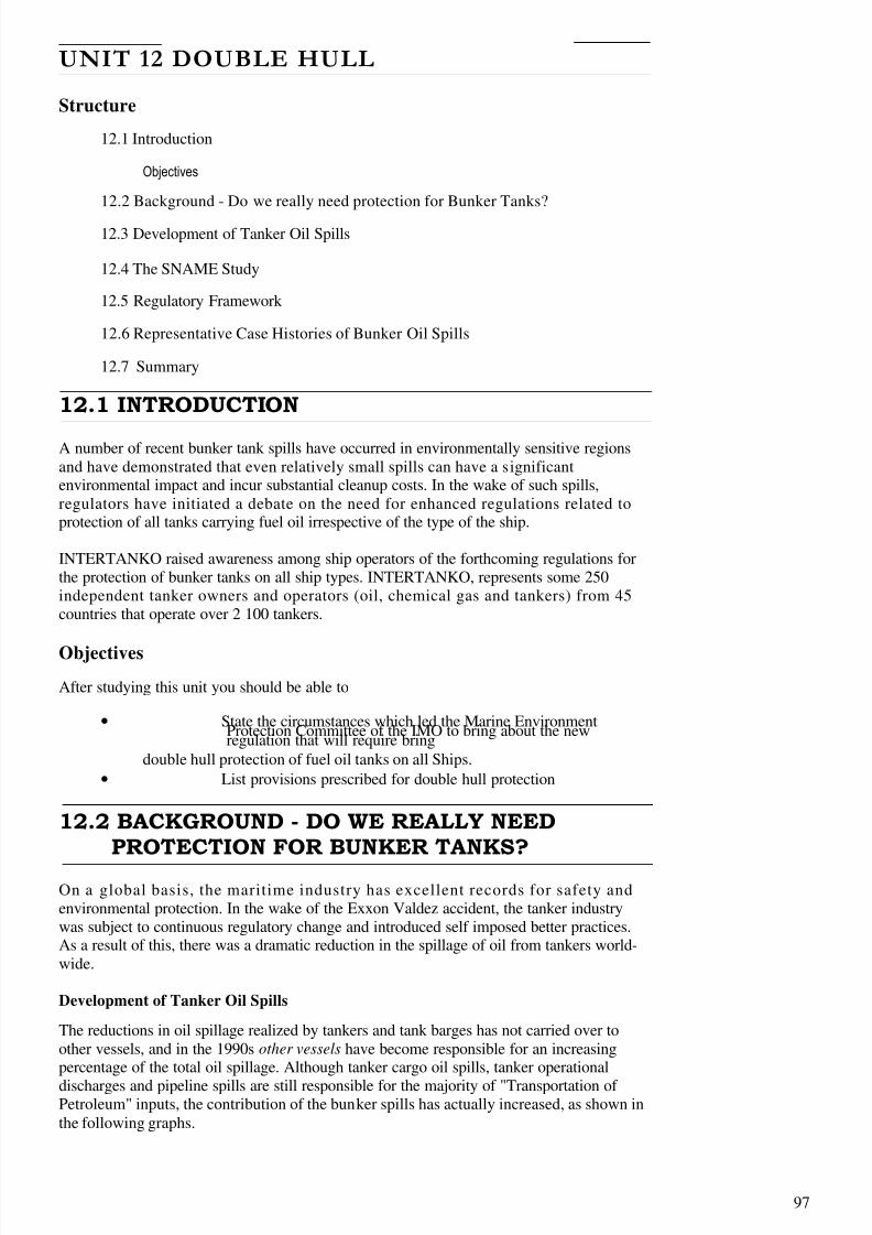
8/6/2019 IMU Future Issues
http://slidepdf.com/reader/full/imu-future-issues 96/123
97
UNIT 12 DOUBLE HULL
Structure
12.1 Introduction
Objectives
12.2 Background - Do we really need protection for Bunker Tanks?
12.3 Development of Tanker Oil Spills
12.4 The SNAME Study
12.5 Regulatory Framework
12.6 Representative Case Histories of Bunker Oil Spills
12.7 Summary
12.1 INTRODUCTION
A number of recent bunker tank spills have occurred in environmentally sensitive regionsand have demonstrated that even relatively small spills can have a significantenvironmental impact and incur substantial cleanup costs. In the wake of such spills,regulators have initiated a debate on the need for enhanced regulations related toprotection of all tanks carrying fuel oil irrespective of the type of the ship.
INTERTANKO raised awareness among ship operators of the forthcoming regulations forthe protection of bunker tanks on all ship types. INTERTANKO, represents some 250independent tanker owners and operators (oil, chemical gas and tankers) from 45countries that operate over 2 100 tankers.
Objectives
After studying this unit you should be able to
• State the circumstances which led the Marine EnvironmentProtection Committee of the IMO to bring about the newregulation that will require bring
double hull protection of fuel oil tanks on all Ships.
• List provisions prescribed for double hull protection
12.2 BACKGROUND - DO WE REALLY NEEDPROTECTION FOR BUNKER TANKS?
On a global basis, the maritime industry has excellent records for safety andenvironmental protection. In the wake of the Exxon Valdez accident, the tanker industrywas subject to continuous regulatory change and introduced self imposed better practices.As a result of this, there was a dramatic reduction in the spillage of oil from tankers world-wide.
Development of Tanker Oil Spills
The reductions in oil spillage realized by tankers and tank barges has not carried over toother vessels, and in the 1990s other vessels have become responsible for an increasingpercentage of the total oil spillage. Although tanker cargo oil spills, tanker operational
discharges and pipeline spills are still responsible for the majority of "Transportation of Petroleum" inputs, the contribution of the bunker spills has actually increased, as shown inthe following graphs.
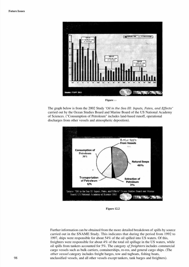
8/6/2019 IMU Future Issues
http://slidepdf.com/reader/full/imu-future-issues 97/123
Further information can be obtained from the more detailed breakdown of spills by source
carried out in the SNAME Study. This indicates that during the period from 1992 to1997, ships were responsible for about 54% of the oil spilled into US waters. Of this,freighters were responsible for about 4% of the total oil spillage in the US waters, whileoil spills from tankers accounted for 5%. The category of freighters includes commercialcargo vessels such as bulk carriers, containerships, ro-ros, and general cargo ships. (Theother vessel category includes freight barges, tow and tugboats, fishing boats,
98 unclassified vessels, and all other vessels except tankers, tank barges and freighters).
Future Issues
Development of tanker oil spills
Figure 12.1
The graph below is from the 2002 Study "Oil in the Sea III: Inputs, Fates, and Effects"
carried out by the Ocean Studies Board and Marine Board of the US National Academyof Sciences. ("Consumption of Petroleum" includes land-based runoff, operationaldischarges from other vessels and atmospheric deposition).
Natural Seeps
46%
Extraction of Petroleum
3%
A ReleaseofPatiote= '--- Sourcelay Arod dwi&,(l 99DZ1
B.nl,er Spji'sFrom Vessels
10,11,
Consumption of
Petroleum38%
Figure 12.2
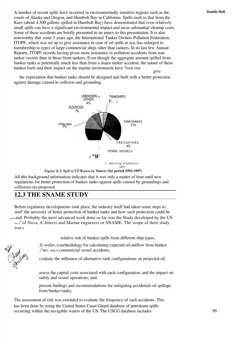
8/6/2019 IMU Future Issues
http://slidepdf.com/reader/full/imu-future-issues 98/123
Double HullA number of recent spills have occurred in environmentally sensitive regions such as thecoasts of Alaska and Oregon, and Humbolt Bay in California. Spills such as that from theKure (about 4,500 gallons spilled in Humbolt Bay) have demonstrated that even relativelysmall spills can have a significant environmental impact and incur substantial cleanup costs.Some of these accidents are briefly presented in an annex to this presentation. It is alsonoteworthy that some 3 years ago, the International Tanker Owners Pollution Federation,ITOPF, which was set up to give assistance in case of oil spills at sea, has enlarged itsmembership to types of large commercial ships other than tankers. In its last few AnnualReports, ITOPF records having given more assistance in pollution accidents from non-
tanker vessels than in those from tankers. Even though the aggregate amount spilled frombunker tanks is potentially much less than from a major tanker accident, the nature of thesebunker fuels and their impact on the marine environment have given rise
give
the expectation that bunker tanks should be designed and built with a better protectionagainst damage caused in collision and grounding.
FREIGHTERS4%
— OTHER VESSELS
1"W ( . . d u c t i n g f r i g h t e r s )
14%
Figure 12.3: Spill in US Waters by Source (for period 1992-1997)
All this background information indicates that it was only a matter of time until newregulations for better protection of bunker tanks against spills caused by groundings andcollisions are proposed.
12.3 THE SNAME STUDY
Before regulatory developments took place, the industry itself had taken some steps tostudy the necessity of better protection of bunker tanks and how such protection could be
quantif ied. Probably the most advanced work done so far was the Study developed by the USSociet
y of Naval Ar
chitects and Marine engineers or SNAME. The scope of their studywas to
UNKNOWN or
OTHER4%
SOURCES_ 7%
PIPELINESP0,
TANKSHIPS
Fr , %
TANK3ARGES31%
relative risk of bunker spills from different ship types,
,f(-weluv,,a methodology for calculating expected oil outflow from bunker.d
1Mk1--kiiL
,e commercial vessel accidents;
cvaluatc the influence of alternative tank configurations on projected oil
assess the capital costs associated with each configuration, and the impact onsafety and vessel operations; and;
present findings and recommendations for mitigating accidental oil spillagefrom bunker tanks.
The assessment of risk was extended to evaluate the frequency of such accidents. This
has been done by using the United States Coast Guard database of petroleum spillsoccurring within the navigable waters of the US. The USCG database includes 99

8/6/2019 IMU Future Issues
http://slidepdf.com/reader/full/imu-future-issues 99/123
Future Issues information on the amount of spillage, the type of vessel involved, and causality. The frequency and volume of spillage from bunker tanks on freighters is estimated through analysis of thesehistorical data. The SNAME Ad Hoc Panel also examined six accidents involving breaching of fuel oil tanks. These case histories provide insight into the types of accidents that occur, and theseverity of hull damage encountered.
Arranging double hull protection around the bunker tanks is one means of mitigating therisk of spillage. The location and size of the fuel oil tanks also influence the likelihood andexpected volume of oil spills.
12.5 REGULATORY FRAMEWORK
Regulation 13F of MARPOL 73/78 requires all new tankers above 5,000 DWT to have a doublehull, a mid-deck, or an alternative arrangement approved by the International MaritimeOrganization (IMO). OPA 90 mandates double hull construction for all new tank vesselscalling US waters. However, both regulations apply only to cargo oil tanks, and any fuel oiltanks located within the cargo tank length. The cargo tank length extends from the aft-mostcargo tank boundary to the collision bulkhead. As tankers typically have their bunker tanksarranged in the engine room, these tanks can be located adjacent to the shell.
The motivation behind the new regulation is to obtain a similar degree of double hullprotection to fuel oil tanks on ships as to that of carg o tanks in oil tankers.
At its 53rd session in July 2005, IMO's Marine Environment Protection Committee (MEPC)approved for future adoption a new MARPOL Annex 1 regulation on oil fuel tank protection.
The draft regulation is intended to apply to all ships with an ag g regate oil fuel capacity of 600 M3 and above delivered on or after 1 August 2010. The draft regulation includesrequirements fora maximum capacity limitation of 2,500 m3 per oil fuel tank, their protectedlocation and performance standards for accidental oil fuel outflow, as an alternative. The draftregulation also requires Administrations to consider general safety aspects, including theneed for maintenance and inspection of wing and double bottom tanks or spaces, whenapproving the design and construction of ships in accordance with the regulation.
IMO's Marine Environment Protection Committee, MEPC, have completed the work on anew regulation that will require double hull protection of fuel oil tanks on any kind of ship. This regulation will apply to all ships with an aggregate oil fuel capacity of 600 m3 andabove:
• For which the building contract is placed on or after [ I August 2007]; or
• In the absence of a building contract, the keels of which are laid or which areat a similar stage of construction on or after [1 February 2008]; or
• The delivery of which is on or after [1 August 2010]; or which have
undergone a major conversion? for which the contract is placed after[1 August 2007]; or
• In the absence of contract, the construction work of which is begun after[1 February 2008]; or
• Which is completed after [I August 2010].
100
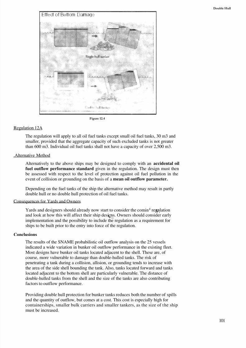
8/6/2019 IMU Future Issues
http://slidepdf.com/reader/full/imu-future-issues 100/123
Double Hull
Figure 12.4
Regulation 12A
The regulation will apply to all oil fuel tanks except small oil fuel tanks, 30 m3 andsmaller, provided that the aggregate capacity of such excluded tanks is not greaterthan 600 m3. Individual oil fuel tanks shall not have a capacity of over 2,500 m3.
.Alternative Method
Alternatively to the above ships may be designed to comply with an accidental oilfuel outflow performance standard given in the regulation. The design must thenbe assessed with respect to the level of protection against oil fuel pollution in theevent of collision or grounding on the basis of a mean oil outflow parameter.
Depending on the fuel tanks of the ship the alternative method may result in partlydouble hull or no double hull protection of oil fuel tanks.
Consequences for Yards and Owners
Yards and designers should already now start to consider the coming regulationV,and look at how this will affect their ship designs. Owners should consider earlyC_implementation and the possibility to include the regulation as a requirement forships to be built prior to the entry into force of the regulation.
Conclusions
The results of the SNAME probabilistic oil outflow analysis on the 25 vesselsindicated a wide variation in bunker oil outflow performance in the existing fleet.Most designs have bunker oil tanks located adjacent to the shell. These are, of course, more vulnerable to damage than double-hulled tanks. The risk of penetrating a tank during a collision, allision, or grounding tends to increase withthe area of the side shell bounding the tank. Also, tanks located forward and tankslocated adjacent to the bottom shell are particularly vulnerable. The distance of double-hulled tanks from the shell and the size of the tanks are also contributingfactors to outflow performance.
Providing double hull protection for bunker tanks reduces both the number of spillsand the quantity of outflow, but comes at a cost. This cost is especially high for
containerships, smaller bulk carriers and smaller tankers, as the size of the shipmust be increased.
101

8/6/2019 IMU Future Issues
http://slidepdf.com/reader/full/imu-future-issues 101/123
Future Issues
102
12.6 REPRESENTATIVE CASE HISTORIES OF BUNKER OIL SPILLS
Case histories for six accidents involving damage to bunker tanks are summarized below.C L-
These include two high energy collisions (the President Washington - Hanjin Hong Kongenergy 1~
and the Alexia - Eno, two allisions (the Julie N and the Kure), and two groundings (theKuroshima and the New Larissa).
COLLISION : PRESIDENT WASHINGTON – HANJIN HONGKONG
In May 1994, at the entrance to Pusan Harbor, the containership Hanjin Hong
Kong struck the containership President Washington on the port side near
amidships. The bow of the Hanjin Hong Kong penetrated the side shell of the President Washington in way of an empty bunker tank and an adjacent ballast tank. extending about 2.5 metres beyond the longitudinal bulkhead. Two adjacent cargo holds wereflooded. There was only minor oil pollution to the harbour from the residual HFO inthe damaged bunker tank. The tank arrangement on the President es] damage
is representative of most container ships where the significantpercentage of bunker oil is stored in wing tanks outboard of the cargo holds. However,it is likely that the extent of damage from the penetration of the Hanjin Hong Kong
bow would have exceeded any practical double hull protection of the bunker tank in this high energy collision.
Figure 12.5: President Washington
COLLISION – ENIF - ALEXIA
Figure 12A Enif and Alexia
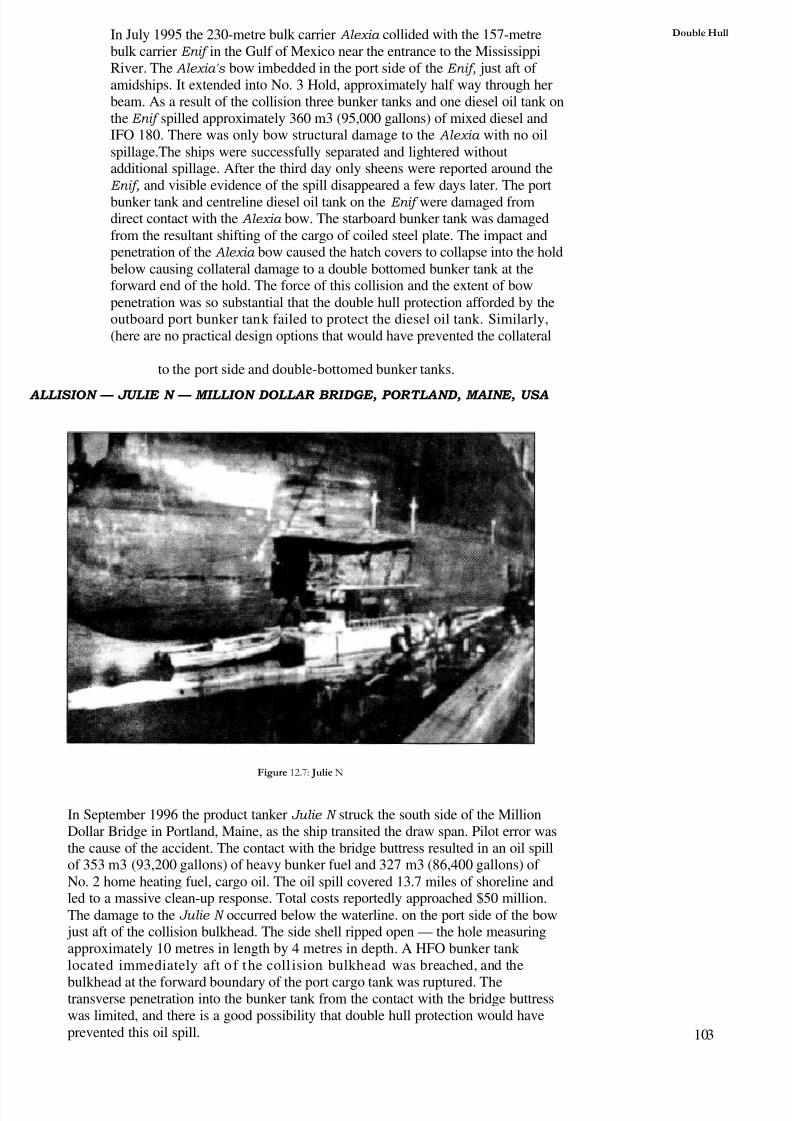
8/6/2019 IMU Future Issues
http://slidepdf.com/reader/full/imu-future-issues 102/123
Double HullIn July 1995 the 230-metre bulk carrier Alexia collided with the 157-metrebulk carrier Enif in the Gulf of Mexico near the entrance to the MississippiRiver. The Alexia's bow imbedded in the port side of the Enif, just aft of amidships. It extended into No. 3 Hold, approximately half way through herbeam. As a result of the collision three bunker tanks and one diesel oil tank onthe Enif spilled approximately 360 m3 (95,000 gallons) of mixed diesel andIFO 180. There was only bow structural damage to the Alexia with no oilspillage.The ships were successfully separated and lightered withoutadditional spillage. After the third day only sheens were reported around theEnif, and visible evidence of the spill disappeared a few days later. The portbunker tank and centreline diesel oil tank on the Enif were damaged fromdirect contact with the Alexia bow. The starboard bunker tank was damagedfrom the resultant shifting of the cargo of coiled steel plate. The impact andpenetration of the Alexia bow caused the hatch covers to collapse into the holdbelow causing collateral damage to a double bottomed bunker tank at theforward end of the hold. The force of this collision and the extent of bowpenetration was so substantial that the double hull protection afforded by theoutboard port bunker tank failed to protect the diesel oil tank. Similarly,(here are no practical design options that would have prevented the collateral
to the port side and double-bottomed bunker tanks.
ALLISION — JULIE N — MILLION DOLLAR BRIDGE, PORTLAND, MAINE, USA
Figure 12.7: Julie N
In September 1996 the product tanker Julie N struck the south side of the MillionDollar Bridge in Portland, Maine, as the ship transited the draw span. Pilot error wasthe cause of the accident. The contact with the bridge buttress resulted in an oil spillof 353 m3 (93,200 gallons) of heavy bunker fuel and 327 m3 (86,400 gallons) of No. 2 home heating fuel, cargo oil. The oil spill covered 13.7 miles of shoreline andled to a massive clean-up response. Total costs reportedly approached $50 million.The damage to the Julie N occurred below the waterline. on the port side of the bow just aft of the collision bulkhead. The side shell ripped open — the hole measuringapproximately 10 metres in length by 4 metres in depth. A HFO bunker tank located immediately aft of the coll ision bulkhead was breached, and the
bulkhead at the forward boundary of the port cargo tank was ruptured. Thetransverse penetration into the bunker tank from the contact with the bridge buttresswas limited, and there is a good possibility that double hull protection would haveprevented this oil spill. 103
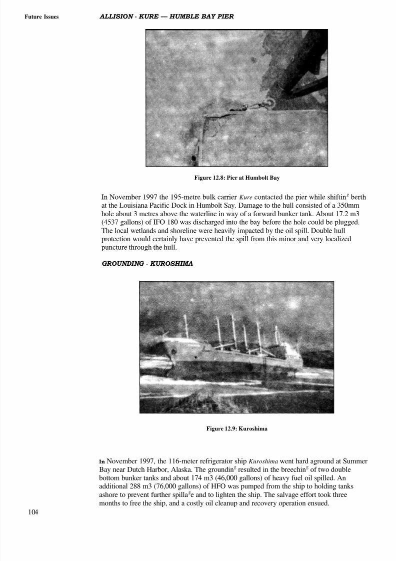
8/6/2019 IMU Future Issues
http://slidepdf.com/reader/full/imu-future-issues 103/123
Future Issues ALLISION - KURE — HUMBLE BAY PIER
Figure 12.8: Pier at Humbolt Bay
In November 1997 the 195-metre bulk carrier Kure contacted the pier while shifting berthat the Louisiana Pacific Dock in Humbolt Say. Damage to the hull consisted of a 350mmhole about 3 metres above the waterline in way of a forward bunker tank. About 17.2 m3(4537 gallons) of IFO 180 was discharged into the bay before the hole could be plugged.The local wetlands and shoreline were heavily impacted by the oil spill. Double hullprotection would certainly have prevented the spill from this minor and very localizedpuncture through the hull.
GROUNDING - KUROSHIMA
Figure 12.9: Kuroshima
In November 1997, the 116-meter refrigerator ship Kuroshima went hard aground at SummerBay near Dutch Harbor, Alaska. The grounding resulted in the breeching of two doublebottom bunker tanks and about 174 m3 (46,000 gallons) of heavy fuel oil spilled. Anadditional 288 m3 (76,000 gallons) of HFO was pumped from the ship to holding tanksashore to prevent further spillage and to lighten the ship. The salvage effort took threemonths to free the ship, and a costly oil cleanup and recovery operation ensued.
104

8/6/2019 IMU Future Issues
http://slidepdf.com/reader/full/imu-future-issues 104/123
Double HullThis oil spill would likely have been averted if the bunker tanks were located outside of
the double bottom spaces.
GROUNDING - NEW CARISSA
Figure 12.10: New Carissa
In early February 1999 the wood chip bulk carrier New Carissa drifted aground off the central Oregon coast. Initially, though hard aground on a sand bottom, therewas no known oil spill. As storm seas pounded the ship against the bottom, oil beganto leak from the ship, and pollute the nearby coastline. Bunker fuel was located inthree centreline double-bottomed tanks below Cargo Holds No. 2 to No. 4, and an
additional double-bottomed tank on the portside below Cargo Hold No.5. Diesel oilwas stored in the starboard double-bottomed tank across from the No. 5 DB. At thetime of the grounding the ship had approximately 60% bunkers on board, consistingof about 1,363 m3 (360,000gallons) of HFO and 114 m3 (30,000 gallons) of dieseloil. It is difficult to know how much HFO escaped from the grounded vessel, and howmuch burned-off during the salvage operation. Estimates of HFO spillage range from189 m3 (50,000 gallons) to 265 m3 (70,000 gallons). To date, salvage and oil spi llclean-up costs have exceeded $20 million. The bunker tank arrangement on theNew Carissa was typical of many bulk carriers where bunker oil is predominantlystored in double-bottomed tanks below the cargo holds. However, it is uncertainwhether alternative bunker tank arrangements would have averted this spill. Thestructural failure and breaking up of the vessel would probably have opened up any
tanks in the midships region of the vessel.regio
SAQ I
What factors influenced greater attention to conservation of energy andalternative sources of energy?
(b) Briefly describe the various sources of energy being harnessed by man.
(c) Define "Renewable Source of Energy" and cite examples.
(d) Describe the working principle of harnessing Tidal Energy and Wave
Energy.
(e) Compare the pros and cons of (i) Tidal Energy (ii) Hydropower energy.
105

8/6/2019 IMU Future Issues
http://slidepdf.com/reader/full/imu-future-issues 105/123
Future Issues What prompted an international maritime debate on double bottomprotection for Fuel Oil Tanks?
What did the SNAME study intend to achieve?
To which vessels does Regulation 12A of Annex 1 of the MARPOL apply?
What alternative method has been suggested to pre-empt fuel oil pollution?
What effect has this new regulation had on Ship Owners?
12.7 SUMMARY
In this module we have made a brief study of case histories involving six accidents wherebunker tanks were damaged and the new IMO regulation that will require double bullprotection of fuel oil tanks.
Note: Some of the pictureslimages used in this Unit have been sourced from the internet. Wewish to thank the creators/publishers for the usage of their material.
106
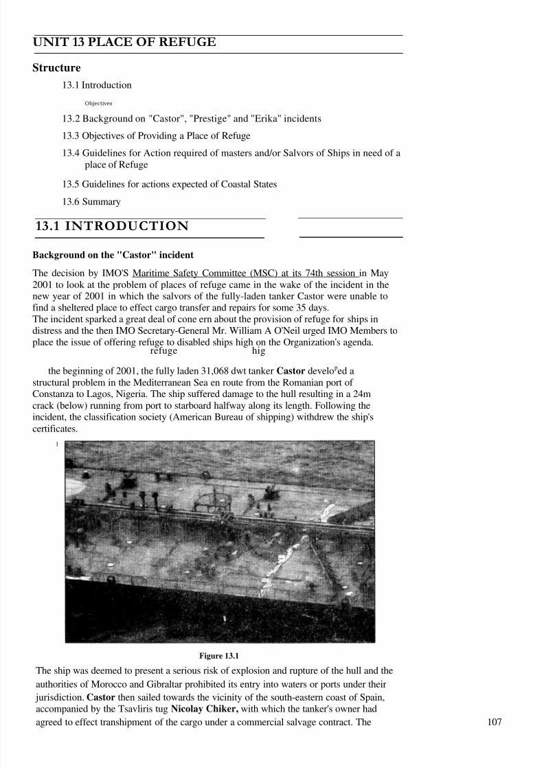
8/6/2019 IMU Future Issues
http://slidepdf.com/reader/full/imu-future-issues 106/123
UNIT 13 PLACE OF REFUGE
Structure
13.1 Introduction
Objectives
13.2 Background on "Castor", "Prestige" and "Erika" incidents
13.3 Objectives of Providing a Place of Refuge
13.4 Guidelines for Action required of masters and/or Salvors of Ships in need of aplace of Refuge
13.5 Guidelines for actions expected of Coastal States
13.6 Summary
13.1 INTRODUCTION
Background on the "Castor" incident
The decision by IMO'S Maritime Safety Committee (MSC) at its 74th session in May2001 to look at the problem of places of refuge came in the wake of the incident in thenew year of 2001 in which the salvors of the fully-laden tanker Castor were unable tofind a sheltered place to effect cargo transfer and repairs for some 35 days.The incident sparked a great deal of cone ern about the provision of refuge for ships indistress and the then IMO Secretary-General Mr. William A O'Neil urged IMO Members toplace the issue of offering refuge to disabled ships high on the Organization's agenda.
refuge hig
the beginning of 2001, the fully laden 31,068 dwt tanker Castor developed astructural problem in the Mediterranean Sea en route from the Romanian port of Constanza to Lagos, Nigeria. The ship suffered damage to the hull resulting in a 24m
crack (below) running from port to starboard halfway along its length. Following theincident, the classification society (American Bureau of shipping) withdrew the ship'scertificates.
I
Figure 13.1
The ship was deemed to present a serious risk of explosion and rupture of the hull and theauthorities of Morocco and Gibraltar prohibited its entry into waters or ports under their
jurisdiction. Castor then sailed towards the vicinity of the south-eastern coast of Spain,accompanied by the Tsavliris tug Nicolay Chiker, with which the tanker's owner had
agreed to effect transhipment of the cargo under a commercial salvage contract. The 107
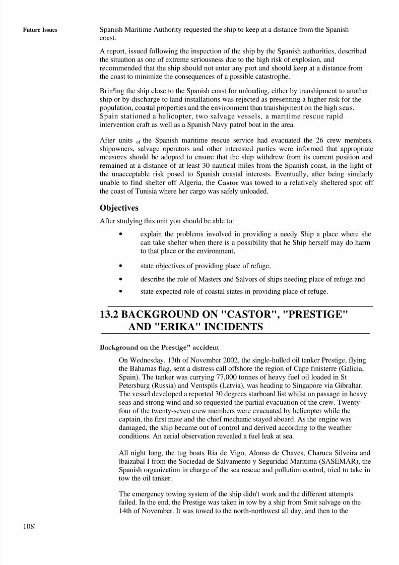
8/6/2019 IMU Future Issues
http://slidepdf.com/reader/full/imu-future-issues 107/123
Future Issues Spanish Maritime Authority requested the ship to keep at a distance from the Spanishcoast.
A report, issued following the inspection of the ship by the Spanish authorities, describedthe situation as one of extreme seriousness due to the high risk of explosion, andrecommended that the ship should not enter any port and should keep at a distance fromthe coast to minimize the consequences of a possible catastrophe.
Bringing the ship close to the Spanish coast for unloading, either by transhipment to another
ship or by discharge to land installations was rejected as presenting a higher risk for thepopulation, coastal properties and the environment than transhipment on the high seas.Spain stationed a helicopter, two salvage vessels, a maritime rescue rapidintervention craft as well as a Spanish Navy patrol boat in the area.
After units of the Spanish maritime rescue service had evacuated the 26 crew members,shipowners, salvage operators and other interested parties were informed that appropriatemeasures should be adopted to ensure that the ship withdrew from its current position andremained at a distance of at least 30 nautical miles from the Spanish coast, in the light of the unacceptable risk posed to Spanish coastal interests. Eventually, after being similarlyunable to find shelter off Algeria, the Castor was towed to a relatively sheltered spot off the coast of Tunisia where her cargo was safely unloaded.
Objectives
After studying this unit you should be able to:
• explain the problems involved in providing a needy Ship a place where shecan take shelter when there is a possibility that he Ship herself may do harmto that place or the environment,
• state objectives of providing place of refuge,
• describe the role of Masters and Salvors of ships needing place of refuge and
• state expected role of coastal states in providing place of refuge.
13.2 BACKGROUND ON "CASTOR", "PRESTIGE"AND "ERIKA" INCIDENTS
Background on the Prestige" accident
On Wednesday, 13th of November 2002, the single-hulled oil tanker Prestige, flyingthe Bahamas flag, sent a distress call offshore the region of Cape finisterre (Galicia,Spain). The tanker was carrying 77,000 tonnes of heavy fuel oil loaded in StPetersburg (Russia) and Ventspils (Latvia), was heading to Singapore via Gibraltar.
The vessel developed a reported 30 degrees starboard list whilst on passage in heavyseas and strong wind and so requested the partial evacuation of the crew. Twenty-four of the twenty-seven crew members were evacuated by helicopter while thecaptain, the first mate and the chief mechanic stayed aboard. As the engine wasdamaged, the ship became out of control and derived according to the weatherconditions. An aerial observation revealed a fuel leak at sea.
All night long, the tug boats Ria de Vigo, Alonso de Chaves, Charuca Silveira andlbaizabal I from the Sociedad de Salvamento y Seguridad Maritima (SASEMAR), theSpanish organization in charge of the sea rescue and pollution control, tried to take intow the oil tanker.
The emergency towing system of the ship didn't work and the different attemptsfailed. In the end, the Prestige was taken in tow by a ship from Smit salvage on the14th of November. It was towed to the north-northwest all day, and then to the
108'
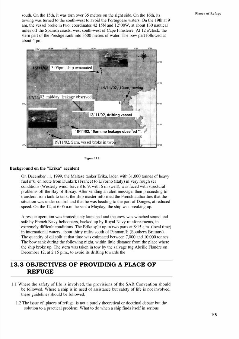
8/6/2019 IMU Future Issues
http://slidepdf.com/reader/full/imu-future-issues 108/123
south. On the 15th, it was torn over 35 metres on the right side. On the 16th, itstowing was turned to the south-west to avoid the Portuguese waters. On the 19th at 9am, the vessel broke in two, coordinates 42 15N and 12°08W, at about 130 nauticalmiles off the Spanish coasts, west south-west of Cape Finisterre. At 12 o'clock, thestern part of the Prestige sank into 3500 metres of water. The bow part followed atabout 4 pm.
Places of Refuge
;I IW
02, midday, leakage observed
is
13/ 11/02, drifting vessel
18/11/02, 10arn, no leakage observ
ed "'.
19/11/02, Sam, vessel broke in two
3.05pm, ship evacuated
W%
W4,
—1.
Figure 13.2
Background on the "Erika" accident
On December 11, 1999, the Maltese tanker Erika, laden with 31,000 tonnes of heavyfuel n°6, en route from Dunkirk (France) to Livorno (Italy) in very rough seaconditions (Westerly wind, force 8 to 9, with 6 m swell), was faced with structuralproblems off the Bay of Biscay. After sending an alert message, then proceeding totransfers from tank to tank, the ship master informed the French authorities that thesituation was under control and that he was heading to the port of Donges, at reducedspeed. On the 12, at 6:05 a.m. he sent a Mayday: the ship was breaking up.
A rescue operation was immediately launched and the crew was winched sound andsafe by French Navy helicopters, backed up by Royal Navy reinforcements, inextremely difficult conditions. The Erika split up in two parts at 8:15 a.m. (local time)in international waters, about thirty miles south of Penmarc'h (Southern Brittany).
The quantity of oil spilt at that time was estimated between 7,000 and 10,000 tonnes.The bow sank during the following night, within little distance from the place wherethe ship broke up. The stern was taken in tow by the salvage tug Abeille Flandre onDecember 12, at 2:15 p.m., to avoid its drifting towards the
13.3 OBJECTIVES OF PROVIDING A PLACE OFREFUGE
1.1 Where the safety of life is involved, the provisions of the SAR Convention shouldbe followed. Where a ship is in need of assistance but safety of life is not involved,these guidelines should be followed.
1.2 The issue of .places of refuge. is not a purely theoretical or doctrinal debate but thesolution to a practical problem: What to do when a ship finds itself in serious
109

8/6/2019 IMU Future Issues
http://slidepdf.com/reader/full/imu-future-issues 109/123
F u t u r e I s s u e s difficulty or in need of assistance without, however, presenting a risk to the safety of life of persons involved. Should the ship be brought into shelter near the coast or intoa port or, conversely, should it be taken out to sea?
1.3 When a ship has suffered an incident, the best way of preventing damage or pollutionfrom its progressive deterioration would be to lighten its cargo and bunkers; and torepair the damage. Such an operation is best carried out in a place of refuge.
1.4 However, to bring such a ship into a place of refuge near a coast may endanger thecoastal State, both economically and from the environmental point of view, and local
authorities and populations may strongly object to the operation. -
1.5 While coastal States may be reluctant to accept damaged or disabled ships intotheir area of responsibility due primarily to the potential for environmental damage,in fact it is rarely possible to deal satisfactorily and effectively with a marine casualtyin open sea conditions.
1.6 In some circumstances, the longer a damaged ship is forced to remain at the mercy of the elements in the open sea, the greater the risk of the vessel's condition
deteriorating or the, sea, weather or environmental situation changing and therebybecoming a greater potential hazard.
1.7 Therefore, granting access to a place of refuge could involve a political decisionwhich can only be taken on a case-by-case basis with due consideration given tothe balance between the advantage for the affected ship and the environmentresulting from bringing the ship into a place of refuge and the risk to theenvironment resulting from that ship being near the coast.
Background
1.8 There are circumstances under which it may be desirable to carry out a cargoC~
transfer operation or other operations to prevent or minimize damage or pollution.For this purpose, it will usually be advantageous to take the ship to a place of refuge.
1.9 Taking such a ship to a place of refuge would also have the advantage of limiting
the extent of coastline threatened by damage or pollution, but the specific areachosen may be more severely threatened. Consideration must also be given to thepossibility of taking the affected ship to a port or terminal where the transfer orrepair work could be done relatively easily. For this reason the decision on thechoice and use of a place of refuge will have to be carefully considered.
1.10 The use of places of refuge could encounter local opposition and involve politicaldecisions. The coastal States should recognize that a properly argued technical case,based on a clear description of the state of the casualty, would be of great value inany negotiations which may take place.
Purpose of the Guidelines
1.12 The purpose of these Guidelines is to provide Member Governments, shipmasters,companies (particularly in connection with the ISM Code and procedures arising therefrom), and salvors with a framework enabling them to respond effectively and in sucha way that, in any given situation, the efforts of the shipmaster and shipping companyconcerned and the efforts of the government authorities involved are complementary.In particular, an attempt has been made to arrive at a common framework forassessing the situation of ships in need of assistance.
1.13 These Guidelines do not address the issue of operations for the rescue of persons atsea, inasmuch as the practical difficulties that have given rise to the examination of theissue of places of refuge relate to problems other than those of rescue. Two situationscan arise:
1 1 0

8/6/2019 IMU Future Issues
http://slidepdf.com/reader/full/imu-future-issues 110/123
Places of Refugethe ship, according to the master's assessment, is in need of assistancebut not in a distress situation (about to sink, fire developing, etc.) thatrequires the evacuation of those on board; or
those on board have already been rescued, with the possible exceptionof those who have stayed on board or have been placed on board in anattempt to deal with the situation of the ship.
1.14 If, however, in an evolving situation, the persons on board find themselves in
distress, the rules applicable to rescue operations under the SAR Convention, theIAMSAR Manual and documents arising there from have priority over the presentGuidelines (and procedures arising here from).
1.15 In any case the competent MRCC should be informed about any situation whichmay develop into a SAR incident.
1 16 Even though a .rescue. operation, as defined in the International Convention onMaritime Search and Rescue (SAR) is not the case, the safety of persons mustnevertheless be constantly borne in mind in the application of these Guidelines,particularly in two respects:
if the ship poses a risk (explosion, serious pollution, etc.) to the life of
persons in the vicinity (crews of salvage vessels, port workers, inhabitants of the coastal area, etc.),
if persons voluntarily stay (master, etc.) or go (fire-fighters and other experts,personnel of marine salvage or towage companies, etc.) on board to attempt toovercome the difficulties experienced by the ship.
1 17 These Guidelines do not address the issue of liability and compensation for damageresulting from a decision to grant or deny a ship a place of refuge.
Definitions
1.18 Ship in need of assistance means a ship in a situation, apart from one requiring
rescue of persons on board that could give rise to loss of the vessel or anenvironmental or navigational hazard.
1.19 Place of refuge means a place where a ship in need of assistance can take action toenable it to stabilize its condition and reduce the hazards to navigation, and toprotect human life and the environment.
1.20 MAS means a maritime assistance service, as defined in resolution A.950(23),responsible for receiving reports in the event of incidents and serving as the point of contact between the shipmaster and the authorities of the coastal State in the eventof an incident.
13.4 GUIDELINES FOR ACTION REQUIRED OFMASTERS AND/OR SALVORS OF SHIPS INNEED OF A PLACE OF REFUGE
Appraisal of the situation
2.1 The master should, where necessary with the assistance of the company and/or thesalver, identify the reasons for his/her ship's need of assistance.
Identification of hazards and assessment of associated risks
2.2 Having made the appraisal referred to in paragraph 2.1 above, the master, wherenecessary with the assistance of the company and/or the salver, should estimate the
consequences of the potential casualty, in the following hypothetical situations,taking into account both the casualty assessment factors in their possession andalso the cargo and bunkers on board:
- if the ship remains in the same position; 111

8/6/2019 IMU Future Issues
http://slidepdf.com/reader/full/imu-future-issues 111/123
Future Issues - if the ship continues on its voyage;
− if the ship reaches a place of refuge; or
− if the ship is taken out to sea.
Identification of the required actions
2.3 The master and/or the salver should identify the assistance they require from thecoastal State in order to overcome the inherent danger of the situation.
Contacting the authority of the coastal State
2.4 The master and/or the salver should make contact with the coastal State in order totransmit to it the particulars referred to in paragraphs 2.1 to 2.3 above. They must inany case transmit to the coastal State the particulars required under the internationalconventions in force. Such contact should be made through the coastal State'sMaritime Assistance Service (MAS), as referred to in resolution A.950(23).
Establishment of responsibilities and communications with all parties involved .
2.5 The master and/or the salver should notify the MAS of the actions that are intendedto be taken and within what period of time.
2.6 The MAS should notify the master and/or the salver of the facilities that it canmake available with a view to assistance or admittance of the ship to a place of refuge, 11' required.
Response actions
2.7 Subject, where necessary, to the coastal State's prior consent, the shipmaster and theshipping company concerned should take any necessary response actions, suchas signing a salvage or agreement or the provision of any other service for
the purpose of dealing with the situation.
2.8 The master, the company and, where applicable, the salver of the ship shouldc• omply with the practical requirements resulting from the coastal State's decision-C7making process referred to in paragraphs 3.12 to 3.14.
Reporting procedures
2.9 The-reporting procedures should be in accordance with the procedures laid down inthe safety management system of the ship concerned under the ISM Code or resolutionA.852(20) on Guidelines for a structure of an integrated system of contingencyplanning for shipboard emergencies, as appropriate.
13.5 GUIDELINES FOR ACTIONS EXPECTED OFCOASTAL STATES
3.1 Under international law, a coastal State may require the ship's master or company totake appropriate action within a prescribed time limit with a view to halting a threatof danger. In cases of failure or urgency, the coastal State can exercise its authorityin taking responsive action appropriate to the threat.
3.2 It is therefore important that coastal States establish procedures to address theseissues, even if no established damage and/or pollution have occurred.
3.3 Coastal States should, in particular, establish a Maritime Assistance Servict(MAS).
Assessment of places of refuge
112

8/6/2019 IMU Future Issues
http://slidepdf.com/reader/full/imu-future-issues 112/123
Places of RefugeGeneric assessment and preparatory measures
3.4 It is recommended that coastal States endeavor to establish procedures consistentwith these Guidelines by which to receive and act on requests for assistance with aview to authorizing, where appropriate, the use of a suitable place of refuge.
3.5 The maritime authorities (and. where necessary, the port authorities) should, foreach place of refuge, make an objective analysis of the advantages anddisadvantages of allowing a ship in need of assistance to proceed to a place of refuge.
Unless neighboring States make the necessary arrangements to establish a jointservice.
3.6 The aforementioned analysis, which should take the form of contingency plans, is tobe in preparation for the analysis provided for below when an incident occurs.
3.7 The maritime authorities, port authorities, authorities responsible for shore sidesafety and generally all governmental authorities concerned should ensure that anappropriate system for information-sharing exists and should establishcommunications and alert procedures (identification of contact persons, telephonenumbers, etc.), as appropriate.
3.8 The aforementioned authorities should plan the modalities for a joint assessment of the situation.
Event-specific assessment
Analysis factors
3.9 This analysis should include the following points:
− seaworthiness of the ship concerned, in particular buoyancy, stability,availability of means of propulsion and power generation, docking ability,etc.,
− nature and condition of cargo, stores, bunkers, in particular hazardous goods;
− distance and estimated transit time to a place of refuge-,
− whether the master is still on board;
− the number of other crew and/or salvors and other persons on board and anassessment of human factors, including fatigue;
− the legal authority of the country concerned to require action of the ship inneed of assistance;
− whether the ship concerned is insured or not insured;
− if the ship is insured, identification of the insurer, and the limits of liability
available;
− agreement by the master and company of the ship to the proposals of thecoastal State/salver to proceed or be brought to a place of refuge;
− provisions of the financial security required;
− commercial salvage contracts already concluded by the master or companyof the ship;
− information on the intention of the master and/or salver;
designation of a representative of the company at the coastal Stateconcerned;
risk evaluation factors and− any measures already taken.
113

8/6/2019 IMU Future Issues
http://slidepdf.com/reader/full/imu-future-issues 113/123
Future Issues Expert analysis
3.10 An inspection team designated by the coastal State should board the ship, whenappropriate and if time allows, for the purpose of gathering evaluation data. Theteam should be composed of persons with expertise appropriate to the situation.
3.11 The analysis should include a comparison between the risks involved if the shipremains at sea and the risks that it would pose to the place of refuge and itsenvironment. Such comparison should cover each of the following points:
− safeguarding of human life at sea;
− safety of persons at the place of refuge and its industrial and urbanenvironment (risk of fire or explosion. toxic risk, etc.);
risk of pollution;
if the place of refuge is a port, risk of disruption to the port's operation(channels, docks, equipment, other installations);
evaluation of the consequences if a request for place of refuge is refused,
including the possible effect on neighboring States; and
due regard should be given, when drawing the analysis, to the preservationof the hull, machinery and cargo of the ship in need of assistance.
After the final analysis has been completed, the maritime authority should ensure that theother authorities concerned are appropriately informed.
Decision-making process for the use of a place of refuge
3.12 When permission to access a place of refuge is requested, there is no obligation forthe coastal State to grant it, but the coastal State should w eigh all the factors and risksin a balanced manner and give shelter whenever reasonably possible.
3.13 In the light of the outcome of the assessment provided for above, the coastal Stateshould decide to allow or refuse admittance, coupled, where necessary, withpractical requirements.
3.14 The action of the coastal State does not prevent the company or its representativefrom being called upon to take steps with a view to arranging for the ship in need of assistance to proceed to a place of refuge. As a general rule, if the place of refuge isa port, a security in favor of the port will be required to guarantee payment of all expenses which may be incurred in connection with its operations, such as:measures to safeguard the operation, port dues, pilotage, towage, mooring operations,miscellaneous expenses, etc.
13.6 SUMMARY
We have learnt about the tanker accidents which took place between 1999 to 2002 andthe problems which the ship's captain faced with different authorities. It is a fact that a shipwhich is in need of assistance or in a serious difficulty could possibly be a threat to the portand it may he difficult for the authorities to decide whether she should be brought closer tothe port or be towed further away from the port.
In this module we have learnt about the guidelines to be followed for the ships which arein the need for a place of refuge.
114

8/6/2019 IMU Future Issues
http://slidepdf.com/reader/full/imu-future-issues 114/123
UNIT 14 GREEN PASSPORT
Structure
14.1 Introduction
Objectives
14.2 Brief History of the Issue of Ship Recycling in IMO
14.3 IMO Guidelines on Ship Recycling
14.4 Reporting System for Ships Destined for Recycling
14.5 Ship Recycling Fund
14.6 Future Working Arrangements
14.7 Guidelines for the development of the Ship Recycling Plan
14.8 Conclusions
14.9 Summary
14.1 INTRODUCTION
Ship recycling contributes to sustainable development and is the mostenvironmentally friendly way of disposing of ships with virtually every part of thehull and machinery capable of being re-used. However, while the principle of shiprecycling is a sound one, the reported status of working practices and
environmental standards in recycling facilities in certain parts of the world oftenleaves much to be desired.
1.2 Noting the growing concerns about environmental safety, health and welfare matters inthe ship recycling industry, and the need to reduce the environmental, occupational
health and safety risks related to ship recycling, as well as the need to secure thesmooth withdrawal of ships that have reached the end of their operating lives, theInternational Maritime Organization (IMO) has taken swift action to develop arealistic and effective solution to the problem of ship recycling, which will take intoaccount the particular characteristics of the world of maritime transport.
Figure 14.1
115

8/6/2019 IMU Future Issues
http://slidepdf.com/reader/full/imu-future-issues 115/123
Future Issues
Figure 14.2
Objectives
After studying this unit you should be able to:
• describe meaning of the term 'Green Passport',
• enumerate salient features of the guidelines to all thestakeholders in ship recycling.
14.2 BRIEF HISTORY OF THE ISSUE OF SHIP
RECYCLING IN IMO
2.1 The issue of ship recycling was first brought to the attention of the IMO MarineEnvironment Protection Committee (MEPC) at its forty-second session in 1998and at the following sessions of the Committee it was generally agreed that IMO hasan important role to play in ship recycling, including preparation of a ship beforerecycling commences, and a co-coordinating role towards the ILO and the BaselConvention in recycling matters. At MEPC 47 (March 2002), the Committee agreedthat, for the time being, IMO should develop recommendatory guidelines to beadopted by an Assembly resolution.
14.3 IMO GUIDELINES ON SHIP RECYCLING
3.1 As mentioned in the above paragraph 2.2, the IMO Guidelines on Ship Recycling L,were adopted on 5 December 2003 by resolution A.962(23).
Objectives and Background3.2 The Guidelines have been developed to provide guidance to flag, port andguidance flag
States, ship owners, ship recycling facilities, ship builders and marineequipment suppliers as to "best practice", which takes into account the shiprecycling process throughout the life cycle of the ship. The Guidelines seek to:
encourage recycling as the best means to dispose of ships at the end of their operating lives;
provide guidance in respect of the preparation of ships for recyclingand minimizing the use of potentially hazardous materials and wastegeneration during a ship's operating life;
during
foster inter-agency co-operation; and
encourage all stakeholders to address the issue of ship recycling.
116

8/6/2019 IMU Future Issues
http://slidepdf.com/reader/full/imu-future-issues 116/123
Green Passport
Figure 14.3: Safety and Working environment for workers — here productionof reinforcement bars
Figure 14.4: Identification of Potentially Hazardous Materials
3.3 The Guidelines place a significant emphasis on the identification of potentiallyhazardous materials on board ships prior to recycling and introduce the concept of the Green Passport. The Green Passport for ships is a document providinginformation with regard to materials known to be potentially hazardous utilised inthe construction of the ship, its equipment and systems. This document shouldaccompany the ship throughout its operating life and successive owners of the shipshould maintain the accuracy of the Green Passport and incorporate into it allrelevant design and equipment changes; with the final owner delivering thedocument, with the ship, to the recycling facility.
3.4 Acknowledging that a number of the problems associated with ship recycling might beaddressed at the design and construction stage, the Guidelines encourage shipdesigners and shipbuilders to take due account of the ship's ultimate disposal whendesigning and constructing a ship.
117

8/6/2019 IMU Future Issues
http://slidepdf.com/reader/full/imu-future-issues 117/123
Future Issues
Figure 14.5: Design and Construction of Ships
3.5 The use of materials which can be recycled in a safe and environmentally soundmanner, the minimization of the use of materials known to be potentially hazardousto health and the environment, the consideration of structural designs that couldfacilitate ship recycling and the promotion of the use of techniques and designs which,without compromising safety or operational efficiency, contribute towards thefacilitation of the recycling operation are some of t he recommendationsprovided by the Guidelines with regard to the design and construction of ships.
3.6 Manufacturers of marine equipment that contains hazardous substances are alsoencouraged to design the equipment so as to facilitate the safe removal of thosesubstances, or give advice as to how such substances can be safely removed at the
end of the working life of the equipment.
Figure 14.6: Use of Potentially Hazordous substances
3.7 Minimization of the use of potentially hazordous substances and of waste generation isalso recommended for the lifetime of ships and therefore ship owners should:
118
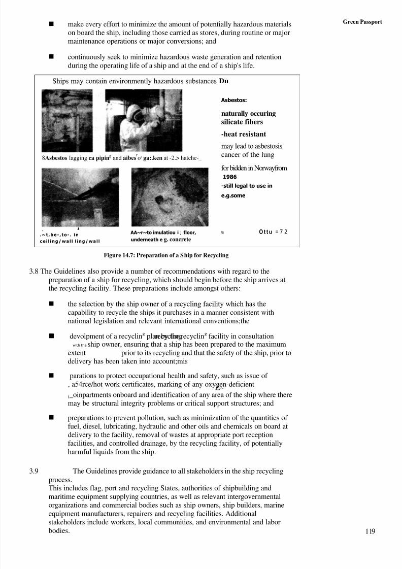
8/6/2019 IMU Future Issues
http://slidepdf.com/reader/full/imu-future-issues 118/123
Green Passport make every effort to minimize the amount of potentially hazardous materials
on board the ship, including those carried as stores, during routine or majormaintenance operations or major conversions; and
continuously seek to minimize hazardous waste generation and retentionduring the operating life of a ship and at the end of a ship's life.
Figure 14.7: Preparation of a Ship for Recycling
3.8 The Guidelines also provide a number of recommendations with regard to thepreparation of a ship for recycling, which should begin before the ship arrives atthe recycling facility. These preparations include amongst others:
the selection by the ship owner of a recycling facility which has thecapability to recycle the ships it purchases in a manner consistent withnational legislation and relevant international conventions;the
devolpment of a recycling plan by the recycling facility in consultationrecyclingwith the ship owner, ensuring that a ship has been prepared to the maximum
extent prior to its recycling and that the safety of the ship, prior todelivery has been taken into account;mis
parations to protect occupational health and safety, such as issue of , a54rce/hot work certificates, marking of any oxygen-deficientZ~
(_oinpartments onboard and identification of any area of the ship where theremay be structural integrity problems or critical support structures; and
preparations to prevent pollution, such as minimization of the quantities of fuel, diesel, lubricating, hydraulic and other oils and chemicals on board atdelivery to the facility, removal of wastes at appropriate port receptionfacilities, and controlled drainage, by the recycling facility, of potentiallyharmful liquids from the ship.
3.9 The Guidelines provide guidance to all stakeholders in the ship recyclingprocess.This includes flag, port and recycling States, authorities of shipbuilding and
maritime equipment supplying countries, as well as relevant intergovernmentalorganizations and commercial bodies such as ship owners, ship builders, marineequipment manufacturers, repairers and recycling facilities. Additionalstakeholders include workers, local communities, and environmental and laborbodies.
Ships may contain environmently hazardous substances Du
,.~t ,be- , t o- . i n
ce i l in g/wa l l l i n g/wa l l
AA~r~to imulatiou ii ; floor,
underneath e g. concrete
%I O t t u = 7 2
8Asbestos lagging ca piping and aibesro, ga:.ken at -2.> hatche-_
Asbestos:
naturally occuringsilicate fibers
-heat resistant
may lead to asbestosiscancer of the lung
for bidden in Norwayfrom1986
-still legal to use in
e.g.some
119

8/6/2019 IMU Future Issues
http://slidepdf.com/reader/full/imu-future-issues 119/123
uture Issues
Figure 14.8: Role of Stakeholders and other Bodies
3.10 In accordance with the Guidelines:
flag state administrations should promote the application of theGuidelines, establish criteria to declare a ship "ready for recycling", promote2nthe use of ship recycling sales and purchase contract and co-operate withrecycling States to facilitate the implementation of the Guidelines;
port states should promote the widespread use of the Guidelines within theindustry and co-operate with flag States and recycling States to facilitate theirimplementation. It is also stressed that ships destined for recycling aresubject to current port State control procedures, as any other ship, inaccordance with applicable international regulations;
recycling states should introduce, implement and enforce sound legislation andother requirements concerning the recycling of ships, includingmeasures to authorize or license recycling facilities and regulations in relationto the condition of ships purchased for recycling both at the time of purchaseand at the tithe of delivery. They should check that any potentially hazardouswastes, which might be generated during the recycling operation, can besafely handled prior to the delivery of the ship for recycling, and monitor thesafe handling of any hazardous materials generated during the recycling
process. Recycling States should also assess the capabilities of their recyclingfacilities and make available the results of those assessments and ensure that,in authorizing a recycling activity, adequate reception facilities are in place; 0
the shipping industry should continue its co-operation with the otherstakeholders towards improving plans to decommission ships in a safe andenvironmental sound manner and is encouraged to continue the furtherdevelopment of the "Industry Code of Practice on Ship Recycling"; and
the ship recycling industry should take due note of available technicalguidance on ship recycling, develop a code of practice appropriate to thatindustry and improve the quality management system of the recycling
Slugs May contain environmentally hazardous substances such as:
Rad ioac t i ve i so topes : -
used for different purposes
radioactive radiation may among
other give cancer. genetically
injuries and mutation
-as an example radioactive smoke
detectors may be used in Norway but
are forbidden to use in Germany
I s
%4ANAGING KISK
Radioactive in smoke e
120
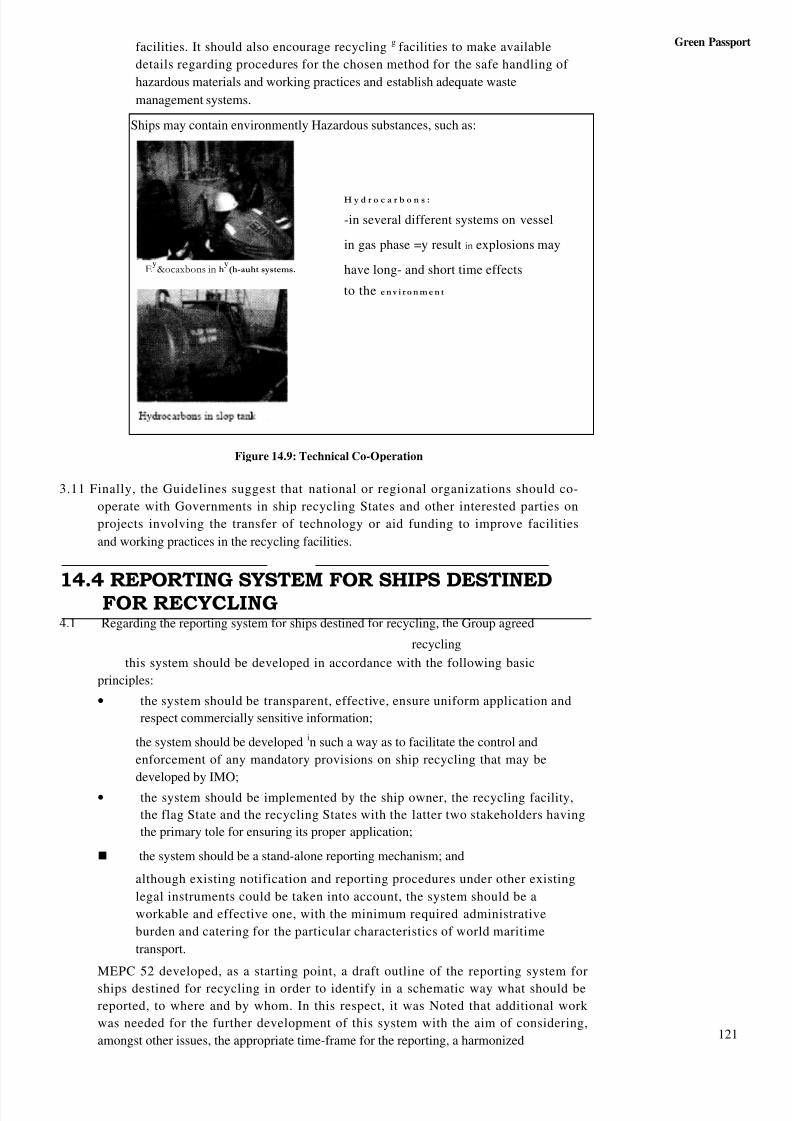
8/6/2019 IMU Future Issues
http://slidepdf.com/reader/full/imu-future-issues 120/123
Green Passportfacilities. It should also encourage recycling g facilities to make available
details regarding procedures for the chosen method for the safe handling of
hazardous materials and working practices and establish adequate waste
management systems.
Figure 14.9: Technical Co-Operation
3.11 Finally, the Guidelines suggest that national or regional organizations should co-
operate with Governments in ship recycling States and other interested parties on
projects involving the transfer of technology or aid funding to improve facilities
and working practices in the recycling facilities.
14.4 REPORTING SYSTEM FOR SHIPS DESTINEDFOR RECYCLING4.1 Regarding the reporting system for ships destined for recycling, the Group agreed
recycling
this system should be developed in accordance with the following basic
principles:
• the system should be transparent, effective, ensure uniform application and
respect commercially sensitive information;
the system should be developed in such a way as to facilitate the control and
enforcement of any mandatory provisions on ship recycling that may be
developed by IMO;
• the system should be implemented by the ship owner, the recycling facility,
the flag State and the recycling States with the latter two stakeholders having
the primary tole for ensuring its proper application;
the system should be a stand-alone reporting mechanism; and
although existing notification and reporting procedures under other existing
legal instruments could be taken into account, the system should be a
workable and effective one, with the minimum required administrative
burden and catering for the particular characteristics of world maritime
transport.
MEPC 52 developed, as a starting point, a draft outline of the reporting system for
ships destined for recycling in order to identify in a schematic way what should be
reported, to where and by whom. In this respect, it was Noted that additional work
was needed for the further development of this system with the aim of considering,
amongst other issues, the appropriate time-frame for the reporting, a harmonized
Ships may contain environmently Hazardous substances, such as:
Ey&ocaxbons in h
y(h-auht systems.
H y d r o c a r b o n s :
-in several different systems on vessel
in gas phase =y result in explosions may
have long- and short time effects
to the e n v i r o n m e n t
121
8/6/2019 IMU Future Issues
http://slidepdf.com/reader/full/imu-future-issues 121/123
Future Issues reporting format and the possible need for additional flow of information betweenthe involved stakeholders.
4.2 "Single list" of the on board potentially hazardous materials:
MEPC 52 agreed that a "single list" of the on board potentially hazardous materialsshould be developed. The "single list" would provide guidance on the identification of potentially hazardous materials on board ships and the preparation of the relevantinventories.
The Committee noted that the Group, having agreed that a standard format should bedeveloped in order to provide for a uniform and consistent application, developed aninitial layout of the "single list" for further consideration in the intercessional period.
The Committee further noted that the Group agreed that:
the "single list" should be user friendly, workable and practicable, specificfor shipboard applications, exclude any generic terms and provideinformation on all hazards associated with the entries in the list;
once the "single list" has been developed it might be appropriate, prior to itsfinalization, to seek input and comments from the Joint ILO/IMO/BCWorking Group on Ship Scrapping.
4.3 Mechanisms to promote the implementation of the Guidelines and Criteria forships to be declared "Ready for Recycling":
4:1
A set of possible and suitable mechanisms for the promotion of the implementation of the Guidelines and an initial draft set of the criteria for ships to be declared "ready forrecycling" were prepared by the intercessional Correspondence Group on ShipRecycling established by MEPC 51 and submitted for consideration and furtherdevelopment to MEPC 52.
At MEPC 52, it was recognized that the outcome of the work outlined in the aboveparagraphs 4.2 to 4.9 would have a significant effect on the further consideration of thepossible mechanisms for the promotion of the implementation of the Guidelines and onthe further development of the criteria for ships to be declared "Ready for Recycling"and, therefore, it was agreed that these issues should be considered at a future session.
Regarding the promotion of the implementation of the Guidelines, the Committeeagreed that a preliminary plan should be developed identifying priorities, achievabledeadlines, and input required from other IMO Committees and Sub-Committees.
4.4 Proposed amendments to the Guidelines:
The Committee, at its fifty-second session, considered a number of proposals foramendments to the Guidelines submitted by the Industry Working Party on ShipRecycling, which was invited to prepare a revised text of the proposed amendmentsto the Guidelines for further consideration in the intercessional period.
14.5 SHIP RECYCLING FUND
MEPC 52, having considered a proposal by Bangladesh, agreed, in principle, to the need forthe establishment of an International Ship Recycling Fund to promote the safe andenvironmentally-sound management of ship recycling through the IMO'S technical co-
operation activities. However, it was agreed that the working arrangements and fundingmechanism of such a Fund would require further consideration and clarification
C
122
8/6/2019 IMU Future Issues
http://slidepdf.com/reader/full/imu-future-issues 122/123
and the IMO'S Technical Co-operation Committee was invited to consider further the Green Passport
arrangements to establish such a dedicated fund.
14.6 FUTURE WORKING ARRANGEMENTS
MEPC 52, taking into account the need to progress the work on ship recycling issues intakingan expeditious manner:
• agreed to the establishment of a correspondence group to further
progress the work in the intercessional period;approved a three-day intercessional meeting of the Working Group on ShipRecycling during the week before MEPC 53 (to be held from 18 to 22 July2005) to consider the issues related to the terms of reference of theCorrespondence Group; and
• agreed to re-establish the Working Group on Ship Recyclingat the next session of the Committee.
14.7 GUIDELINES FOR THE DEVELOPMENT OFTHE SHIP RECYCLING PLAN
In accordance with section 8.3.2 of the IMO Guidelines on Ship Recycling, thedevelopment and implementation of a recycling plan can help ensure that a ship has beenprepared to the maximum extent possible prior to its recycling and that the safety of theship, prior to delivery, has been taken into account. The ship recycling plan should bedeveloped by the recycling facility in consultation with the ship owner, taking intoaccount the potential hazards which may arise during the recycling operation, the relevantnational and international requirements and the facilities available at the recycling facility interms of materials, handling and the disposal of any wastes generated during the recyclingprocess.
MEPC 52 approved the Guidelines for the development of the ship recycling plan, aimed atproviding technical information and guidance for its preparation. These Guidelineshave been circulated by means of MEPC/Circ.419.
14.8 CONCLUSIONS
Recycling is one of the basic principles of sustainable development and ship recycling is,.generally, the best option for all time-expired tonnage. IMO, therefore, encourages andpromotes ship recycling in compliance with the international standards on safety, healthand environment.
MO's work on ship recycling aims at the development of a realistic, pragmatic, well-
balanced. workable and effective solution to the problem of ship recycling, which shouldtake into account the particular characteristics of world maritime transport and the need forsecuring the smooth withdrawal of ships from trade at the end of their operating lives.
C7
Areas where IMO has focused its attention include, but are not limited to:
• the minimization of the use of hazardous materials in the design,construction and maintenance of ships, without compromising their safetyand operational efficiency;
• the identification of potentially hazardous materials on boardships and the preparation of the relevant inventories (e.g. Green Passport);and
• the preparation of ships for recycling in such a manner as toreduce environmental and safety risks and health and welfare concerns asfar as practicable.
123
8/6/2019 IMU Future Issues
http://slidepdf.com/reader/full/imu-future-issues 123/123
Future Issues The issue of ship recycling has been given high priority at the MEPC in order that thepromotion of the implementation of the IMO Guidelines on Ship Recycling and theconsideration of a possible new legally binding IMO instrument on ship recycling areprogressed as efficiently and expeditiously as possible.
IMO maintains close co-operation with ILO and the appropriate bodies of the BaselConvention, with the aim of avoiding duplication of work and overlapping of responsibilities and competencies between the three Organizations.
SAQ 1
(a) What is a place of refuge?
(b) What is the objective of a v/1 seeking a place of refuge?
(c) What do you understand by MAS?
(d) What factors must be taken into account by the Master seeking a place of refuge?
(e) What do the IMO Guidelines expect of Coastal States in cases dealing withv/ls seeking a place of refuge?
(f) What is the concept of the "Green Passport"?
(g) What are the objectives sought in the formation of the Green Passportdocument?
(h) How do the following entities contribute to the success of the Green Passportconcept?
(i) Ship Recycling Agencies
(ii) Ship owners
(iii) Ship recycling States
(i) What do the IMO Guidelines state w.r.t vessels reporting prior proceeding tothe recycling yard?
How must a ship owner plan for the recycling of his vessel? What factors
must be taken into account while preparing such a plan?