
IMRT Quality Assurance · 1 IMRT QA II Chester Ramsey, Ph.D. Stephen Mahan, Ph.D. Thompson Cancer...
21
1 IMRT QA II Chester Ramsey, Ph.D. Stephen Mahan, Ph.D. Thompson Cancer Center Knoxville, Tennessee, U.S.A IMRT Quality Assurance n Why do we need IMRT QA? n Do I really need to do QA for each IMRT patient? n If I use an independent Monitor Unit calculation program do I still need QA for each Patient? n Will I still need to IMRT QA after we’ve treated 500 patients? n If I expand my monthly machine QA can I eliminate IMRT QA for each patient? Medicare Billing Guidelines n The accuracy of dose delivery must be documented for each course of treatment by irradiating a phantom that contains either calibrated film to sample the dose distribution or an equivalent measurement system to verify that the dose delivered is the dose planned n The dosimetry should be verified using an ionization chamber Good Practice Guidelines n Absolute dose must be verified by measurement prior to the delivery of the first IMRT Fraction n Relative (or absolute) dosimetry must be analyzed prior to the delivery of the third fraction using calibrated film or an equivalent measurement system IMRT Quality Assurance What’s the Worst that Could Happen? n Patient Death n Severe Complication n Misadministration n Major Treatment Deviation n Minor Treatment Deviation n Litigation n Lost Revenue IMRT Quality Assurance Least Worst FDA Adverse Event Report (06/16/2004) n Patient Overdosed by 13.8% n Patient subsequently died as a result of complications related to the mistreatment FDA Adverse Event Report (04/07/2005) n Medical center reported that between 2004 and 2005 77 pts received radiation approx 52% in excess of their prescribed dose n The excess radiation was a result of a calculation error by the medical center physicist during calibration n This incident has been recognized/identified as "human error" PDF Creator - PDF4Free v2.0 http://www.pdf4free.com
Transcript of IMRT Quality Assurance · 1 IMRT QA II Chester Ramsey, Ph.D. Stephen Mahan, Ph.D. Thompson Cancer...

1
IMRT QA II
Chester Ramsey, Ph.D.Stephen Mahan, Ph.D.
Thompson Cancer CenterKnoxville, Tennessee, U.S.A
IMRT Quality Assurancen Why do we need IMRT QA?
n Do I really need to do QA foreach IMRT patient?
n If I use an independent MonitorUnit calculation program do Istill need QA for each Patient?
n Will I still need to IMRT QAafter we’ve treated 500patients?
n If I expand my monthlymachine QA can I eliminateIMRT QA for each patient?
Medicare Billing Guidelinesn The accuracy of dose delivery must be documented for each course of
treatment by irradiating a phantom that contains either calibrated film tosample the dose distribution or an equivalent measurement system to verifythat the dose delivered is the dose planned
n The dosimetry should be verified using an ionization chamber
Good Practice Guidelinesn Absolute dose must be verified by measurement prior to the delivery of the
first IMRT Fractionn Relative (or absolute) dosimetry must be analyzed prior to the delivery of
the third fraction using calibrated film or an equivalent measurementsystem
IMRT Quality AssuranceWhat’s the Worst that Could Happen?
n Patient Deathn Severe Complicationn Misadministrationn Major Treatment Deviationn Minor Treatment Deviationn Litigationn Lost Revenue
IMRT Quality Assurance
Least
Worst
FDA Adverse Event Report(06/16/2004)n Patient Overdosed by 13.8%n Patient subsequently died as a
result of complications related tothe mistreatment
FDA Adverse Event Report(04/07/2005)n Medical center reported that
between 2004 and 2005 77 ptsreceived radiation approx 52%in excess of their prescribeddose
n The excess radiation was a resultof a calculation error by themedical center physicist duringcalibration
n This incident has beenrecognized/identified as "humanerror"
PDF Creator - PDF4Free v2.0 http://www.pdf4free.com
2
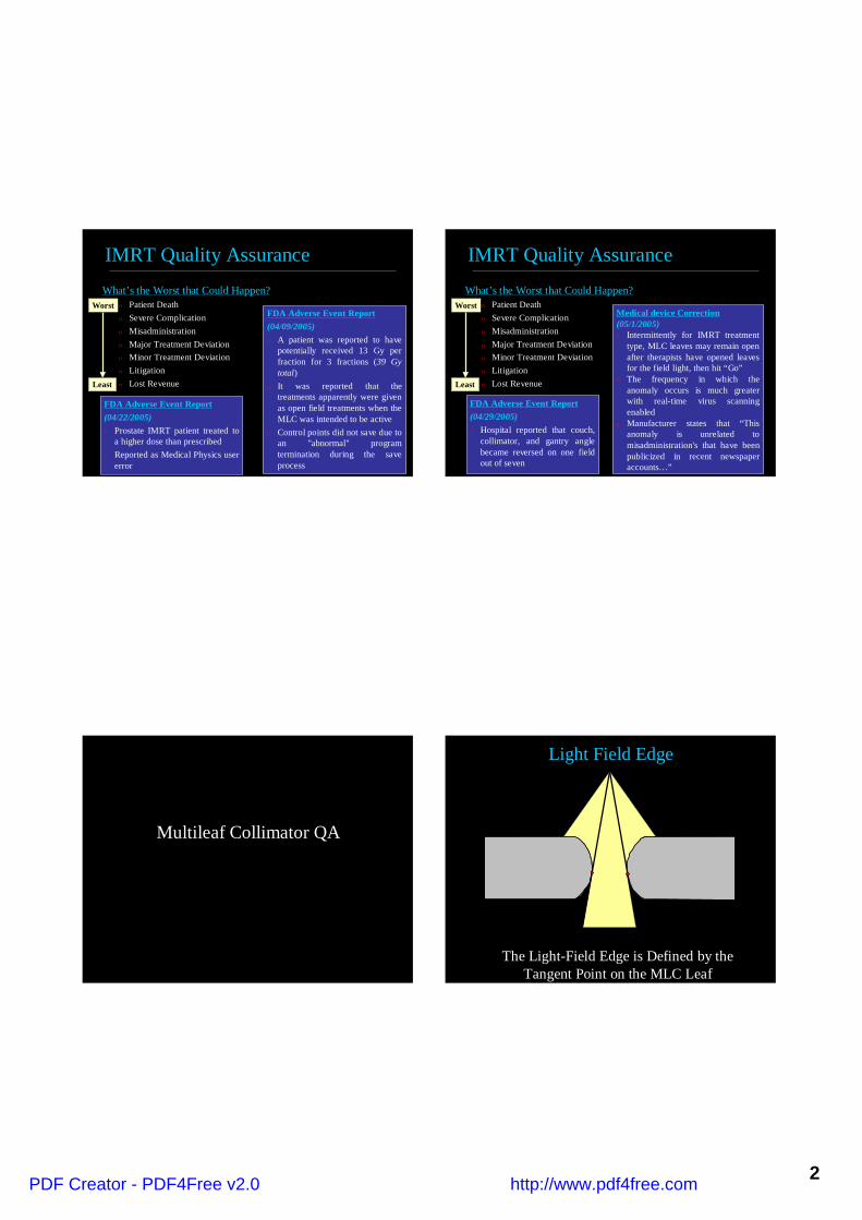
What’s the Worst that Could Happen?n Patient Deathn Severe Complicationn Misadministrationn Major Treatment Deviationn Minor Treatment Deviationn Litigationn Lost Revenue
IMRT Quality Assurance
Least
WorstFDA Adverse Event Report(04/09/2005)n A patient was reported to have
potentially received 13 Gy perfraction for 3 fractions (39 Gytotal)
n It was reported that thetreatments apparently were givenas open field treatments when theMLC was intended to be active
n Control points did not save due toan "abnormal" programtermination during the saveprocess
FDA Adverse Event Report(04/22/2005)n Prostate IMRT patient treated to
a higher dose than prescribedn Reported as Medical Physics user
error
What’s the Worst that Could Happen?n Patient Deathn Severe Complicationn Misadministrationn Major Treatment Deviationn Minor Treatment Deviationn Litigationn Lost Revenue
IMRT Quality Assurance
Least
WorstMedical device Correction(05/1/2005)n Intermittently for IMRT treatment
type, MLC leaves may remain openafter therapists have opened leavesfor the field light, then hit “Go”
n The frequency in which theanomaly occurs is much greaterwith real-time virus scanningenabled
n Manufacturer states that “Thisanomaly is unrelated tomisadministration's that have beenpublicized in recent newspaperaccounts…”
FDA Adverse Event Report(04/29/2005)n Hospital reported that couch,
collimator, and gantry anglebecame reversed on one fieldout of seven
Multileaf Collimator QA
Light Field Edge
The Light-Field Edge is Defined by theTangent Point on the MLC Leaf
PDF Creator - PDF4Free v2.0 http://www.pdf4free.com
3
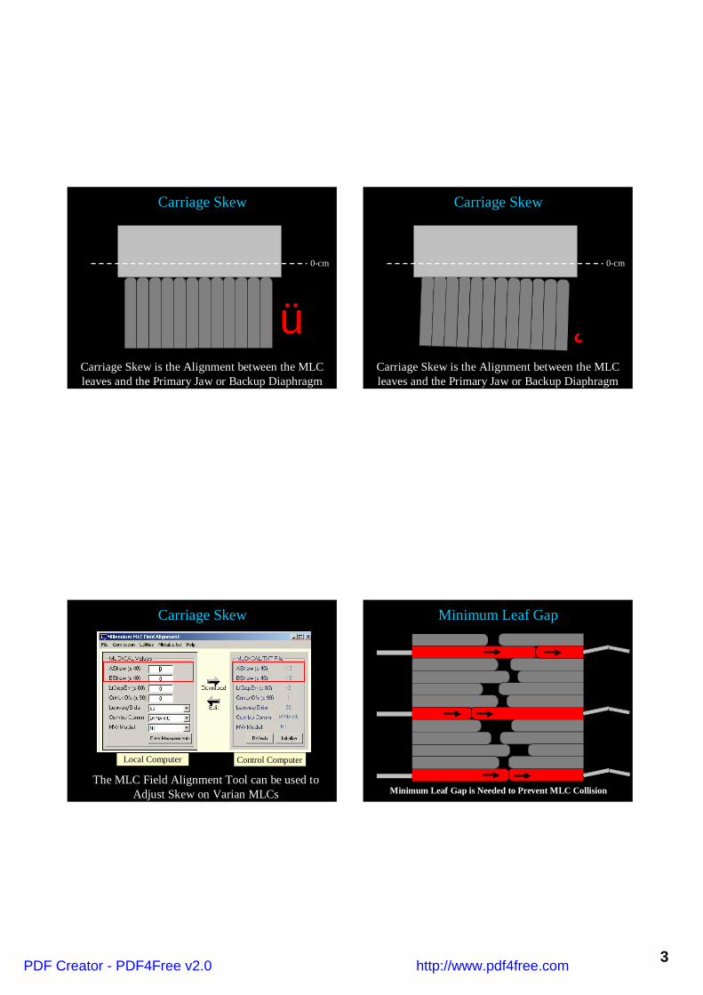
ü
0-cm
Carriage Skew
Carriage Skew is the Alignment between the MLCleaves and the Primary Jaw or Backup Diaphragm
Î
0-cm
Carriage Skew
Carriage Skew is the Alignment between the MLCleaves and the Primary Jaw or Backup Diaphragm
Local ComputerLocal Computer Control ComputerControl Computer
Carriage Skew
The MLC Field Alignment Tool can be used toAdjust Skew on Varian MLCs
Minimum Leaf Gap
Minimum Leaf Gap is Needed to Prevent MLC Collision
PDF Creator - PDF4Free v2.0 http://www.pdf4free.com

4
Minimum Leaf Gapn A directly independent
measurement of the mechanicalgap can be made with a feelergauge
n The opposed pair of MLC leavesare set to a 1-mm field atisocenter
n The gauge should read thedemagnified value at the plane ofthe MLC
n Be aware that vendors havefrequently changed thespecification for this offset
Local ComputerLocal Computer Control ComputerControl Computer
Minimum Leaf Gap
The MLC Field Alignment Tool can be used tothe Leaf Gap Offset on Varian MLCs
X-Ray Field Edge
The Rounded leaves allow SignificantTransmission in the First Millimeter Boyer et al, Med. Phys. 24: 757
Light-FieldEdge
X-RayField Edge
X-Ray FieldEdge = 1 HVL
X-Ray Field Edge
PDF Creator - PDF4Free v2.0 http://www.pdf4free.com

5
X-Ray Field Edge
The Effective Leaf Shift is the DistanceBetween the Light and X-Ray Field Edges
X-Ray Field Edge
The Effective Leaf Shift is the DistanceBetween the Light and X-Ray Field Edges
Effective Leaf Shift
AAPM IMRT subcommittee Med. Phys. 30 (8)
n The Effective Leaf Shift ismeasured using Multiple StaticMLC fields
n The MLC leaves on one side movebeyond the desired position by 1/2the estimated gap width
n The opposing MLC leaves thenmove beyond the desired positionby 1/2 the estimated gap width
n A double exposed film is used tomeasure the junction between thetwo fields
PDF Creator - PDF4Free v2.0 http://www.pdf4free.com

6
AAPM IMRT subcommittee Med. Phys. 30 (8)
Effective Leaf Shift
0.4-mm
0.6-mm
1.2-mm1.4-m
m0.8-m
m1.0-m
m
Varian 6MV
AAPM IMRT subcommittee Med. Phys. 30 (8)
Effective Leaf Shift
1.4-mm
1.6-mm 2.2-m
m2.4-m
m1.8-m
m2.0-m
m
Varian 18MV
Image-Guidance Commissioning
Imaging System Commissioning
n MVCT images can beacquired with slice thicknessof 6-mm (coarse), 4-mm(normal), and 2.5-mm (fine)
n The dose for each slicethickness is measured with aspecial ion chamber
n 2 cm3 collecting volume witha collecting length of +4-cm
n 0.5 (coarse) to 4.0 cGy (fine)is delivered to the imagingvolume for each MVCT
PDF Creator - PDF4Free v2.0 http://www.pdf4free.com

7
Imaging System Commissioning
n Imaging system accuracy is measured by placing an object ina reference position and then CT imaging that object
n An anthropomorphic head phantom is imaged 30 times
Imaging System Commissioning
n The calculated shifts should be 0.0-mm in all directions
n Any non-zero shifts that are calculated represent the totalimaging and fusion accuracy
n The measured (and now published) accuracy is 0.6-mm
Radiographic Film for IMRT QA
Film Calibration
n EDR2 Film (Kodak, Rochester,NY) is a Ready-Pack form ofthe original EC film used forportal localization
n EDR2 is a very slow speed andfine grain film with a usefulrange up to 600 cGy
n Double emulsion layers arecoated on a 0.18-mm Estarbase, which allowsconventional processing
Zhu et al. Med Phys 29: 16870
1
2
3
4
5
0 500 1000 1500cGy
OD
TLXV2EDR
PDF Creator - PDF4Free v2.0 http://www.pdf4free.com
8
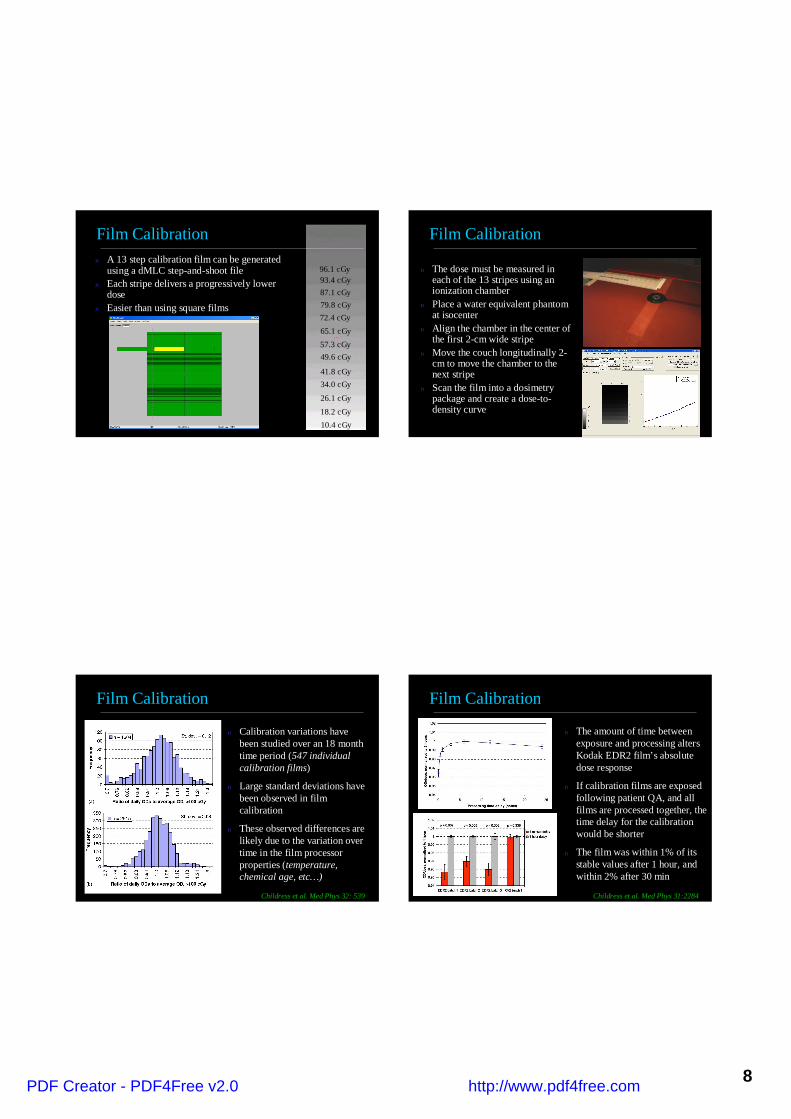
n A 13 step calibration film can be generatedusing a dMLC step-and-shoot file
n Each stripe delivers a progressively lowerdose
n Easier than using square films
96.1 cGy
65.1 cGy57.3 cGy49.6 cGy
41.8 cGy34.0 cGy
26.1 cGy
18.2 cGy10.4 cGy
87.1 cGy79.8 cGy72.4 cGy
93.4 cGy
Film Calibration Film Calibration
n The dose must be measured ineach of the 13 stripes using anionization chamber
n Place a water equivalent phantomat isocenter
n Align the chamber in the center ofthe first 2-cm wide stripe
n Move the couch longitudinally 2-cm to move the chamber to thenext stripe
n Scan the film into a dosimetrypackage and create a dose-to-density curve
Film Calibration
n Calibration variations havebeen studied over an 18 monthtime period (547 individualcalibration films)
n Large standard deviations havebeen observed in filmcalibration
n These observed differences arelikely due to the variation overtime in the film processorproperties (temperature,chemical age, etc…)
Childress et al. Med Phys 32: 539
Film Calibration
n The amount of time betweenexposure and processing altersKodak EDR2 film’s absolutedose response
n If calibration films are exposedfollowing patient QA, and allfilms are processed together, thetime delay for the calibrationwould be shorter
n The film was within 1% of itsstable values after 1 hour, andwithin 2% after 30 min
Childress et al. Med Phys 31:2284
PDF Creator - PDF4Free v2.0 http://www.pdf4free.com

9
IMRT Patient QA Techniques
Planar Dosimetry
Planar Dosimetry is when measurements are taken withbuild-up material one field at a time
Planar Dosimetry
Planar Dosimetry is when measurements are taken withbuild-up material of one field at a time
Composite Dosimetry
Composite Dosimetry is when measurements are taken withbuild-up material for all fields from the treatment gantry angles
PDF Creator - PDF4Free v2.0 http://www.pdf4free.com

10
Composite Dosimetry
Composite Dosimetry is when measurements are taken withbuild-up material for all fields from the treatment gantry angles
Patient Specific Quality Assurance
n The phantom is placedon the treatment andaligned with the REDlasers
n Ion Chamber(s) areused to measureabsolute dose prior tothe first treatment
n Film (or equivalent) isused to measure theshape of the dosedistribution
Sold Water Phantom with Farmer ChamberSold Water Phantom with Farmer Chamber
Patient Specific Quality Assurance
Cylindrical Phantom with Small Volume ChamberCylindrical Phantom with Small Volume Chamber
n The phantom is placedon the treatment andaligned with the REDlasers
n Ion Chamber(s) areused to measureabsolute dose prior tothe first treatment
n Film (or equivalent) isused to measure theshape of the dosedistribution
Patient Specific Quality Assurance
MedMed--Tec Phantom with Small Volume ChamberTec Phantom with Small Volume Chamber
n The phantom is placedon the treatment andaligned with the REDlasers
n Ion Chamber(s) areused to measureabsolute dose prior tothe first treatment
n Film (or equivalent) isused to measure theshape of the dosedistribution
PDF Creator - PDF4Free v2.0 http://www.pdf4free.com

11
The Film is marked at knowThe Film is marked at knowlocations by metal pins that arelocations by metal pins that are
built into the phantombuilt into the phantom
Metal PinsMetal Pins
(0, 11)
(0, -11) (11, -10)
(13.5, -5)
Film Registration
MVCT kVCTkVCT
CT Images are acquired of the phantom and the metal pinsCT Images are acquired of the phantom and the metal pinsare aligned with the planning CT imageare aligned with the planning CT image
Film Registration
Film Registrationn Do not need a phantom
with built-in pins
n The film dosimetrysoftware must have a toolfor registering the film tothe calculated doses
n The Pin Pricks on thefilm are matched toknown points on theplanned doses
n The use of film pricksallows a spatialcalibration of the locationof the doses
Inverse Planning SystemCommissioning
PDF Creator - PDF4Free v2.0 http://www.pdf4free.com

12
Planning System Commissioningn The first step in planning system
commissioning is to developsimple geometric test cases
n In the treatment planning system,contour 5 rectangular structures ona single slice that corresponds to 5-cm depth in phantom
n Contour 2x2, 4x4, 6x6, 8x8, and10x10 squares
n Add a single anterior field
n Using the inverse planningsoftware to created a dose pyramid
200180160140120
Film Plane
Planning System Commissioningn For the next commissioning test,
reverse the dose sequence to createa dose well
n Again, use the inverse planningsystem to create a plan with asingle anterior beam
n Experiment with different leafsequencing options to find a goodbalance between the calculateddose and the number of segments
n Verify these test plans using filmdosimetry on the accelerator
Film Plane
200180160140120
Planning System Commissioning
Gamma (3%/3-mm)Green < 1Red >1
ThresholdGreen < 3%Red >3%
Pyramid
Planning System Commissioning
PDF Creator - PDF4Free v2.0 http://www.pdf4free.com

13
Planning System Commissioning
Gamma (3%/3-mm)Green < 1Red >1
ThresholdGreen < 3%Red >3%
Well
Planning System Commissioning
Planning System Commissioning
XR: 5-mm
25-mm
PTV
Cord
n The next commissioning stepinvolves creating complexmulti-field IMRT treatments
n Create a PTV that is 25-mmthick and Spinal Cord had adiameter of 10-mm
n Create five test cases with theseparation between the PTVand the Spinal Cord set to 2-mm, 4-mm, 6-mm, 8-mm, and10-mm
Planning System Commissioning
XR: 5-mm
25-mm
PTV
Cord
n Prescribe 30 Gy to 90% of thePTV
n The minimum dose to the PTVis 27.9 Gy
n The maximum dose to the PTVis 33Gy
n During optimization minimizethe dose to the spinal cord
n Verify these test plans usingfilm and ion chamber dosimetryon the accelerator
PDF Creator - PDF4Free v2.0 http://www.pdf4free.com
14
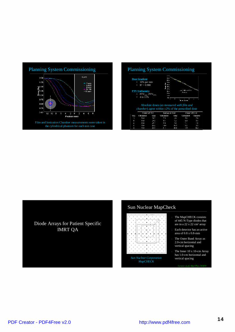
Planning System Commissioning
Film and Ionization Chamber measurements were taken inthe cylindrical phantom for each test case
Planning System Commissioning
Dose Gradient• 10% per mm• R2 = 0.988
PTV Uniformity• PTVmax / PTV95%• 4 to 11%
Absolute doses (as measured with film andchamber) agree within ±2% of the prescribed dose
Diode Arrays for Patient SpecificIMRT QA
Sun Nuclear MapCheck
n The MapCHECK consistsof 445 N-Type diodes thatare in a 22 x 22 cm2 array
n Each detector has an activearea of 0.8 x 0.8-mm
n The Outer Band Array as2.0-cm horizontal andvertical spacing
n The Inner 10 x 10-cm Arrayhas 1.0-cm horizontal andvertical spacingSun Nuclear Corporation
MapCHECKJursinic et al. Med Phys 30:870
PDF Creator - PDF4Free v2.0 http://www.pdf4free.com

15
Sun Nuclear MapCheck
n The N-Diodes are aproprietary design thatmakes them very resistantto radiation damage(compared to other N-TypeDiodes)
n Two acrylic plates that haveconductive surfacessurround the diodes, whichare mounted on a multilayercircuit board
Sun Nuclear CorporationMapCHECK
Jursinic et al. Med Phys 30:870
Sun Nuclear MapCheck
0%
20%
40%
60%
80%
100%
0 50 100 150 200 250 300 350
Dose (cGy)Si
gnal
n The response of the systemis linear with dose
n However, the N-Typediodes do have atemperature coefficient of0.54% / 0C
n As such it is recommendedthat the MapCHECK bestored at a temperture closeto that of the treatmentroom
Sun Nuclear MapCheck
Jursinic et al. Med Phys 30:870
n The system has a radiologicalbuildup of 2 g/cm2 to thedetector junctions
n The physical thickness of thebuild-up is 1.35-cm
n The system also has 2.7g/cm2 of Backscatter
n As such, the system can beused with or without additionwater-equivalent build-upmaterial
95.65-cm98.65-cm
3.0-cm
Sun Nuclear MapCheck
MapCheck
Build-Up (3-cm)
100-
cm
95.6
5-cm
Build-Up
100-
cm 95-c
m
Jursinic et al. Med Phys 30:870
Actual Measurement Setup Treatment Planning Setup
PDF Creator - PDF4Free v2.0 http://www.pdf4free.com
16
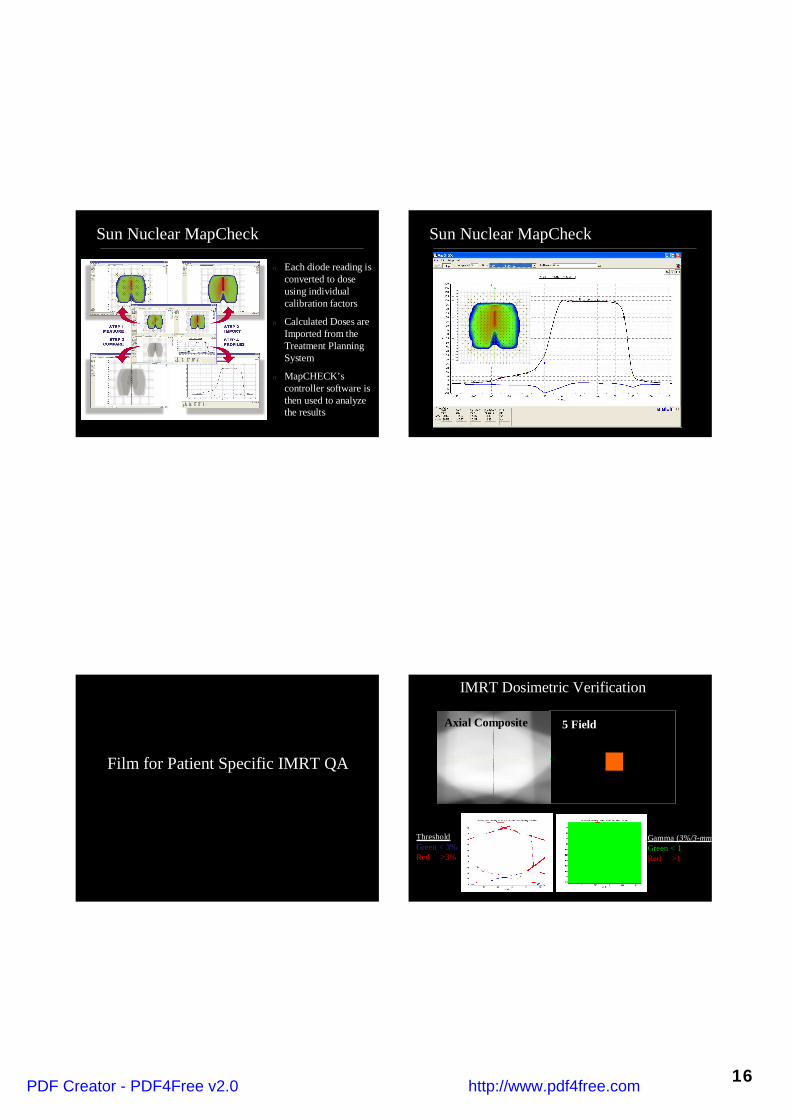
Sun Nuclear MapCheck
n Each diode reading isconverted to doseusing individualcalibration factors
n Calculated Doses areImported from theTreatment PlanningSystem
n MapCHECK’scontroller software isthen used to analyzethe results
Sun Nuclear MapCheck
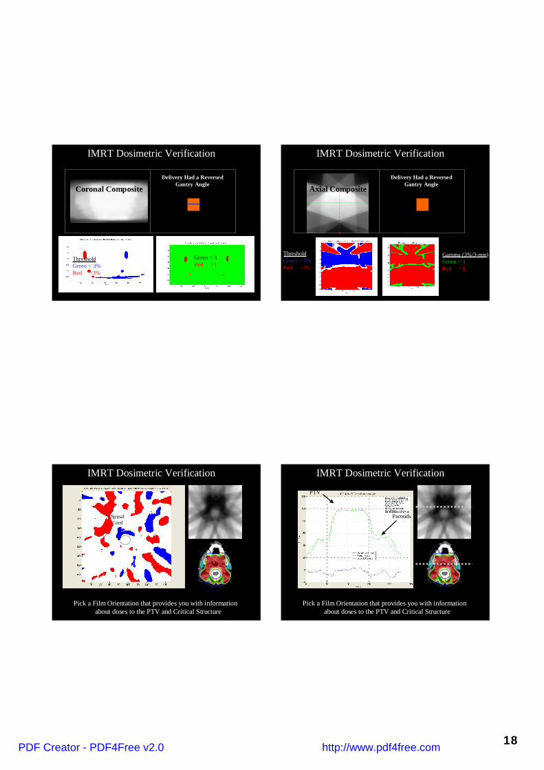
Film for Patient Specific IMRT QA
IMRT Dosimetric Verification
Gamma (3%/3-mm)Green < 1Red >1
ThresholdGreen < 3%Red >3%
5 FieldAxial Composite
PDF Creator - PDF4Free v2.0 http://www.pdf4free.com

17
IMRT Dosimetric Verification IMRT Dosimetric Verification
Gamma (3%/3-mm)Green < 1Red >1
ThresholdGreen < 3%Red >3%
AP Field
>10%
IMRT Dosimetric VerificationLarge Region of Interest
Small Region of Interest
90% pixelswithin ±3%
76% pixelswithin ±3%
Statistics must be calculatedwith a consistent ROI
IMRT Dosimetric Verification
Green < 1Red >1
ThresholdGreen < 3%Red >3%
Coronal Composite
5 Field (Planned)
PDF Creator - PDF4Free v2.0 http://www.pdf4free.com
18
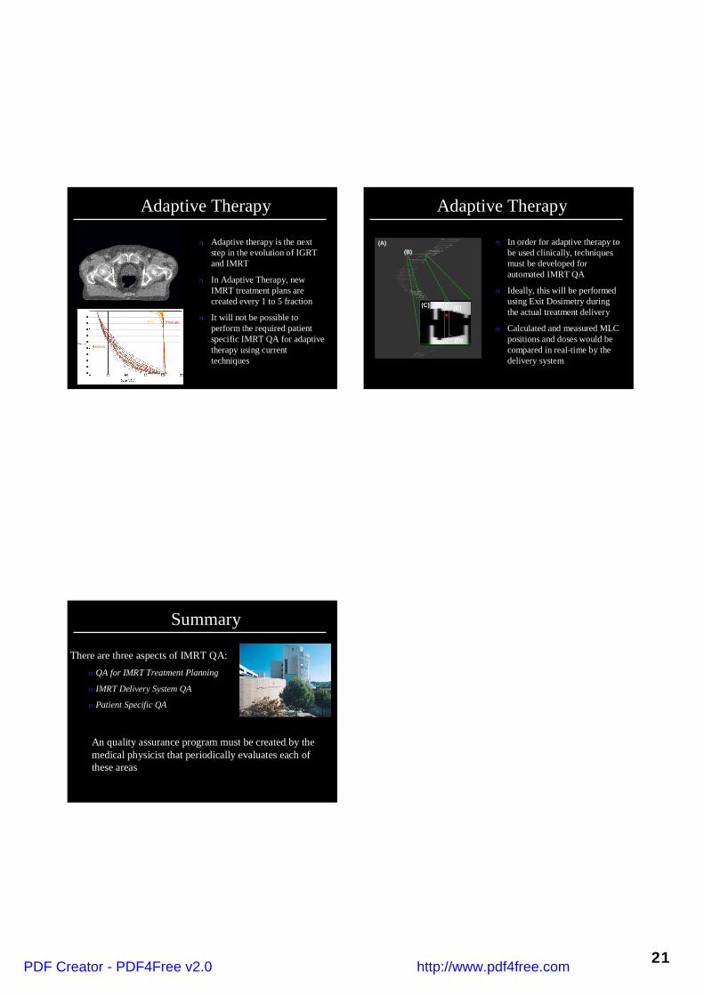
IMRT Dosimetric Verification
Green < 1Red >1
ThresholdGreen < 3%Red >3%
Coronal CompositeDelivery Had a Reversed
Gantry Angle
IMRT Dosimetric Verification
Axial Composite
Gamma (3%/3-mm)Green < 1Red >1
ThresholdGreen < 3%Red >3%
Delivery Had a ReversedGantry Angle
SpinalCord
IMRT Dosimetric Verification
Pick a Film Orientation that provides you with informationPick a Film Orientation that provides you with informationabout doses to theabout doses to the PTVPTV and Critical Structureand Critical Structure
PTV
Parotids
Pick a Film Orientation that provides you with informationPick a Film Orientation that provides you with informationabout doses to theabout doses to the PTVPTV and Critical Structureand Critical Structure
IMRT Dosimetric Verification
PDF Creator - PDF4Free v2.0 http://www.pdf4free.com

19
PTV
SpinalCord
IMRT Dosimetric Verification
Pick a Film Orientation that provides you with informationPick a Film Orientation that provides you with informationabout doses to theabout doses to the PTVPTV and Critical Structureand Critical Structure
Absolute ion chamber readings should be withinAbsolute ion chamber readings should be within ±2%,and must be withinmust be within ±4% of the prescribed doseof the prescribed dose
IMRT Dosimetric Verification
EPID Dosimetry
n Varian Linear AcceleratorsEquipped with AmorphousSilicon EPIDs can be used tofor patient-specific IMRT doseverification
n Planar dosimetry can bemeasured for individual IMRTfields and analyzed using eitherthe Varian Portal VisionDosimetry Software or theRIT113 Dosimetry Software
EPID Dosimetry
PDF Creator - PDF4Free v2.0 http://www.pdf4free.com

20
EPID Dosimetryn Users who have the Varian EPID, Eclipse (version 7.1.13 or
higher), and the Eclipse Portal Vision Dosimetry Upgrade cancalculate a dose map of the true patient plan at the 105cm planein the amorphous silicon panel
n Users who have the Varian EPID and a Third Party PlanningSystem must calculate a homogeneous phantom plan with thedose map calculated at the 105 cm distance
n Images for Third Party Planning Systems are acquired at 0degrees (IEC Scale) and 100 cm SSD with 2cm of solid watersitting directly on the EPID
n NOTE: There is an anti-collision interlock for the EPID arm sothe solid water must be placed on the EPID very gently in orderto not activate this interlock
EPID Dosimetry
Adaptive Therapy
PDF Creator - PDF4Free v2.0 http://www.pdf4free.com
21
n Adaptive therapy is the nextstep in the evolution of IGRTand IMRT
n In Adaptive Therapy, newIMRT treatment plans arecreated every 1 to 5 fraction
n It will not be possible toperform the required patientspecific IMRT QA for adaptivetherapy using currenttechniques
Adaptive Therapy
S.V.
Rectum
Prostate
n In order for adaptive therapy tobe used clinically, techniquesmust be developed forautomated IMRT QA
n Ideally, this will be performedusing Exit Dosimetry duringthe actual treatment delivery
n Calculated and measured MLCpositions and doses would becompared in real-time by thedelivery system
Adaptive Therapy
(A)(B)
(C)
(D)
(E)
There are three aspects of IMRT QA:n QA for IMRT Treatment Planning
n IMRT Delivery System QA
n Patient Specific QA
Summary
An quality assurance program must be created by themedical physicist that periodically evaluates each ofthese areas
PDF Creator - PDF4Free v2.0 http://www.pdf4free.com


