
++ Recent developments in the understanding of fretting fatigue

International Conference on Shot Peening and Blast Cleaning.
IMPROVEMENT OF FRETTING FATIGUE PERFORMANCE OF LARGE STEAM TURBINE BLAIQE
MATERIAL USING BALL PEENING
MCSharma and R.K. Joshi Mechanical Engineering Department,
Maulana Azad College of Technology, Bhopal, India
ABSTRACT
Steam turbine blades have to withstand large amounts of stress and high vibrations. These are highly loaded elements of tur- bines; their premature and unexpected failure can lead to cata- strophic damage to the turbine. The turbine blade roots have fir tree grooves, which are subjected t o high amounts of stress and become stress concentration zones due t o their geometry. Blade roots undergo fretting, and are therefore required t o withstand fretting fatigue.
The work presented in this paper relates t o study improvement in fatigue and fretting fatigue performance of large steam tur- bine blade material using ball peening. During the course of in- vestigation, samples of turbine blade material were ball peened using different peening parameters. Compressive stresses induced were studied in order to arrive at the optimum peening param- eters. Samples were prepared from the turbine blade material w i th notches corresponding t o grooves in the turbine blade roots. The samples were then ball peened at the optimum peening pa- rameter and plain fatigue strength of the samples was deter- mined using the rotating cantilever fatigue test. Fretting fatigue strength of the samples was deduced based on the plain fatigue strength.
KEY WORDS Ball Peening, Fretting, Fretting Fatigue.
INTRODUCTION
Fretting is a complex deterioration phenomenon caused by small amplitude relative motion of t w o mating metallic surfaces against one another. Fretting is caused by small amplitude cyclical move-

ment of t w o solid bodies in close contact and under pressure. The exerted pressures are sufficiently high and the movement sufficiently small so that the debris produced may not escape from their point of origin. The fretting causes shear peaks by friction between the contact zone and non-contact zones on t o which are super imposed local plastic deformation of asperities. There follows micro welds of these asperities under the influ- ence of high contact pressures and the temperatures due to plastic deformation. The minute relative displacement of contact sur- faces subsequently causes the rupture of the asperities, which then oxidize. The phenomenon of metallic fragment dislocation will accelerate under the amplification influence of the oxidized particles, often much harder than the base metal. Scour marks and sever surface damagemill soon appear under the influence of the applied service stresses of the moving parts added to the shear stress due to friction. Fatigue micro cracks will develop and propagate leading to eventual part rupture [ I ] .
Fretting occurs, in general, between t w o tight-fitting surfaces that are subjected to a cyclic relative motion of extremely small amplitude. Although certain aspects of the mechanism of fret- t ing are still not thoroughly understood, the fretting process is generally divided into three parts namely, initial conditions of surface adhesion, oscillation accompanied by the generation of debris, and fatigue and wear in the region of contact [1&8]. Fretting Fatigue ca'n be retarded by the following [ I &2]: -
(a) Improving surface bearing characteristics.
(b) Introducing compressive residual stress.
(c) Increasing material hardness. (d) Reduction of movement amplitude.
Ball peening causes shallow spherical indentations on the sur- face of the work piece resulting in plastic deformation in the shallow layer. This results in creation of a compressive residual

stress zone, which negates the effect of tensile stresses. The compressive stress zone deters initiation of cracks. It also ar- rests the propagation of cracks and thereby, considerably slows the rupture of part through fretting. Ball peening cold work hard- ens the metallic surfaces. This results in considerable increase-in superficial hardening leading to improvement of wear character- istics and resistance to fretting fatigue [ I &5].
Effect of controlled ball peening is [ I ] : -
(a) Creation of minute surface dimples.
(b) Surface strain hardening.
(c) Change of surf ace morphology and friction coefficient.
(d) Induction of compressive residual stresses.
In case of steam turbine blade roots, the concentration of stresses is at the fir tree grooves (fig.1 I), which makes them critical for fretting fatigue. Controlled ball peening improves a number of parameters effecting fatigue and fretting fatigue strength of tur- bine blades [ I &6].
Yves LE Guernic, in his studies on the effect of peening on the plain and fretting fatigue life of steels, had brought out about the improvement achieved in the plain fatigue strength and fretting fatigue strength of XC18 steel by peening. It is inferred from the data that the percentage increase obtained in the fretting fatigue strength was about 1.36 times the percentage increase in the plain fatigue strength for 4 million cycles of failure i.e. 24 hours survival, and about 1.9 times for 1 0 million cycles [ I ] (fig. I ).

Plain fatigue shot peened
Figure 1 EXPERIMENTATION Investigation w a s conducted using f la t tes t samples o f turbine blade material (Cr 1 8 steel) received f rom BHEL Hardwar. The samples were peened using different peening parameters. Surface profi le o f t he samples w a s studied after peening. The residual compressive stresses in the samples were then measured X-Ray dif fract ion technique at Corporate R&D BHEL Hyderabad.
The surface characteristics and residual stresses fo r di f ferent sho t sizes and peening intensit ies are g iven i n subsequent paragraphs.
3.1 mm Steel ball.
(a) Peening intensity- above 0 .6 A (fiq.2). (i) Surface profi le ( in perpendicular directions) : - (aa) Ra - 4 .4pm and 6.1pm. (ab) R max -54 .4pm and 72.8pm (ii) Residual stress a t di f ferent depths f rom surface (f ig.3): -

(aa) At 100pm - (-) 570.4 Mpa. (ab) At 395pm - (-) 646.8 Mpa. (ac) At 505pm - (-) 554.6 Mpa
Peening Intensity 0.6A Peening Intensity 0. 28A
Tank per 5 kg/cm2, discharge 2300 lit./min, working pressure 2 kg lcc
Ball peened, pressure system, 8 m m nozzle
3.1 mm dia steel ball, orifice dia 12.5 m m
Fig. - 2
Peening intensity- 0.6 A. (fiq.3): - Residual stress a t different depths from surface
At 100 pm - (-) 546.8 Mpa.
At 365 pm - (-) 682.0 Mpa.
At 575 pm - (-) 399.8 Mpa

Residual stress, MPa Vs Depth
Depth below shot-peened surface, microns
- A- -0- Sample I Sample I1 Sample 111
(Peening Intensity 0.6A) (Peening Intensity >0.6A)
Fig. - 3
Fig. - 4
(c) Peening intensity- 0.28 A. (fig.2): - (j) Surface profile

(aa) Ra - 1.58 pm. (ab) R max - 16.30 pm. (ii) rResidual stress at different depths from surface (fig.4): - (aa) A t 1 0 0 pm - (-) 4 5 0 Mpa. (ab) A t 3 0 0 pm - (-) 3 5 0 Mpa. (ac) A t 500 pm - (-) 1 5 0 Mpa.
I .5 mm Steel ball. Peening intensity- 0.36 A. (fig.5): - Surface profile Ra - 2.78 pm. R max - 22.34 pm. Residual stress at different depths from surface (fig.6): - A t 100 p m - (-) 5 5 0 Mpa. A t 395 p m - (-) 3 5 0 Mpa. A t 505 pm - (-1 25 Mpa
Fig. - 5 1.5 mm Ball 0 -36 A 1.5 mm Ball 0 -36 A
Peening intensity- 0.3 1 A. (fig.5): -
Surf ace profile
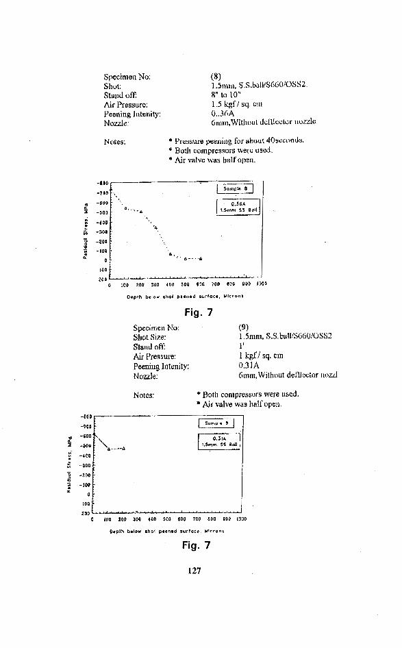
Specimen No: Shot: Stniid o E Air Pressure: Peeoing In te~lity: Noizler
Nates: * Pressure peelling for about 4Osecoa Js. * Bout compressors werc uscd. * Air valve was l ~ n l f open.
Fig. 7 Specimen No: (9) Shot Size: 1.5nlm, S.S. bull/S660!USS2 Stard on': 1' Air Pressure: 1 kgf / sq, cm Peening 111tenity: 0.3 1 A Nozzle: hmm, Without def'llc~tor ~zozd
Notes: * Both compressors were used. * Air valve was half open,
Orplh bmlow shot prcnrd surface, M l c r g n s

1.4 mm shot
Fig. 7
R max - 31 -34 pm. Residual stress at different A t 100 pm - (-) 450 Mpa.
Spe~inleil No; (6) Shot Size: 1.4nindS550/ QSS3 Stand off: 6" to 8" a i r Pressure: 2 kgf/ sq. cm Peeniug Intenity 0.20A No 8mm, Without deflector nozzle
Noies: * Pressure peening used. * Both compressors wow r w d . * Air valve was hulf opm.
Depth bolo* s .d surfaca, Ulcrons
Fig. 8

1.4 m m Shot. Peening intensitv- 0 .20 A. (fig.8): -
(a) Surface profile
(i) Ra-1 .75pm.
(ab) R max - 1 9 . 2 2 p .
'(ii) Residud stress at different depths from surface (fig.9): -
(aa) A t 1 6 0 ~ - (-) 5 5 0 Mpa.
(ab) A$ 3 0 0 ~ ~ - i-) 400 Mpa.
(ac) At 500pm - (-) 2 5 Mpa. 1.2 m m Shot. Peening intensity. 0.23 A. (fig.8): - (a) Surface profile (i) Ra - 2.8pm. (ab) R max - 24.84pm. (ii) ~ e s i d u a l stress at different depths from surface (fig. 10): - (aa) A t 1 0 0 p m - (-) 5 5 0 Mpa. (ab) A t 3 0 0 p m - (-) 3 0 0 Mpa. lac) A t 500 p m - (-) 5 0 Mpa.
Fig. 10
-800
-700
-600 -h
..SO,, A'.. Urnm Shot.
-400
I
-300
-200
-100
0
100
200
'
\ ', I
1 A-A%-w4-.--4
""'-'"'~'*""'A'A*'a'-''l'l"l"'l"'

Control of Surface Roughness. Surface roughness parameter Ra was measured on plain samples , before peening and and after peening w i th 3.1 mm steel balls 0.5A peening intensity. The peening resulted in increase in Ra by about 1.5 pm. Sc,condary peening was carried out using zirconium shots of l p m diameter. This resulted in decrease of Ra by 0.3 t o 0.5pm. The results are tabulated below: -
Note: AM- As machined, PP- Primary Peened, SP- Secondary Peened.
Ser No
1
2
3
4
TURBINE BLADE ROOTS WITH FIR-TREE GROOVES
I 272wwl R
Fig. 11 r
1 2 1 PP+SP 1 1.18
Sample No
1
1
1
2
- 2.5 mm radius - 2.0 mm radius
Codition o'f Sample
A M
PP
PP + SP
PP
Ra inpm
0.68
2.1
1.9
1.72

MTg N ~ T C H O ~ . ~ H M
/ RA Dl usd GL- 10
turbine material were obtained from corporate R&D Division, BHEL Hyderabad. Notches of radii 2.5 mm and 2.0 mm corresponding to the radii of fir tree root grooves of turbine blades (fig. 1 1 ) vvere made on separate fatigue samples (fig. 12). Unpeened fatigue samples were tested to determine the plain fatigue strength us- ing cantilever beam fatigue test for 24-hour survival at 2880 rpm. The average fatigue strength of the unpeened samples using the stair case method for analysis was determined as 273.7 Mpa. The remaining samples were then ball peened using peening par rs as under: -
a). Shot m
b). Working pressure- 2kgIsq cm.
c). Nozzle- 8mm diameter, convergent-divergent type.

d) Orifice diameter - 1 2.5mm
sh& s k k 1 1
e). Peening intensity- 0.6A. f) . Stand of f - 30 cm. g). Coverage-I 50%. h). Impingement angle-90 degrees. i). Peening time- 2 0 0 seconds. j). Equipment used- Pneumatic Peening Plant, Model PB-9182,
Metall ing Equipment Company, Jodhpur.
The ball-peened samples were tested for plain fatigue strength on cantilever rotating fatigue machine for 2 4 hour survival at 2 8 8 0 rpm. The average plain fatigue strength o f the peened samples w i t h notch of 2.5 m m radii was determined as 297.5 Mpa. The peened samples w i t h notch of 2.0 m m radii did not show any increase in the plain fatigue strength, as peening cov- erage of only 20% was achieved on it as against the desired coverage of 150%. The increase in the plain fatigue strength of the samples w i th notch of 2 .5mm radii, after peening was of about 8%.
The surface characteristics and residual compressive stresses

Remarks S.No 1 Shot Size & I Surface Characteristic I Residual Stress in
Refer Fig.2,3&4.
"Residual compressive Stress rapidly decreases to( - )554 Mpa at 505 mm.
#Surface profile has been taken in perpendicular directions
Refer Fig. 5,6 &7.
Refer Fig.8 &9.
Refer Fig. 8 &lo.
Perusal of the results brings out the following deductions on effects of peening: -
(a) Effect on Surface Morphologv.
(i) Surface roughness parameter Ra is higher for higher ball peening intensity.
(ii) Ball peened surfaces have smoother finish as compared to shot peened surfaces for the same peening intensity. Ra for surface peened wi th 1.2 p m shot at 0.23 A intensity is 2.8 pm where as for 3 . l m m steel ball at 0.28A intensity it is 1.58pm.
(b) Residual Compressive Stresses.
(i) Residual compressive stresses at the surface of the test pieces were found to be of lesser magnitude when peening was

done at higher intensity, this may be attributed t o greater metal erosion at the surface due t o increase in peening inten- sity.
(ii) Larger ball size, and peening intensity lead t o higher value of compressive residual stresses in the deeper layers of peened material. The point of maximum slope and peak value of sub- surface compressive residual stress curve, shifts t o deeper layers wi th increase in peening intensity and ball or shot size used.
Effect on fatigue strength. Peening using 3.1 m m steel balls at 0.6A intensity wi th 150% coverage showed an increase in the plain fatigue strength of the test piece by about 8% for test pieces w i th 2.5mm radii notch. The test pieces w i th 2.0 m m radii notch did not show any increase in the fatigue strength, as only about 20% peening coverage was attained on the notch area using 3.1 m m steel balls. If this problem is faced during peening of actual tubine blade roots, then it may be required t o modify the nozzle of the peening equipment t o achieve the de- sired 1 5 0 % peening coverage.
The increase in the fretting fatigue strength of XC 18 Steel, due to ball peening is about 1.36 times the corresponding percent- age increase in the plain fatigue strength for 4 million cycles of failure i.e. 2 4 hour survival. It is 1.9 times the percentage in- crease for 1 0 million cycles of failure [ I ] .In view of the above inference drawn, the increase in the fretting fatigue strength of the fatigue sample with2.5 m m notch radii, after ball peening would be about 10.88% for 4 million cycles of failure.
S-N Curves. S-N Curves for test pieces were plotted at different stress levels. These show a substantial increase in the life of fatigue samples after ball peening to the specified parameters (Fig. 13). In case of samples w i th notch of 2.0mm radii, the fa- tigue life did not increase as the peening coverage was below the desired level.
In v iew of the increase in fatigue strength, of notched fatigue

samples, achieved by ball peening, it will be beneficial t o carry out this treatment on steam turbine blade roots. This will lead to increase in the fatigue and fretting fatigue strength and enhance the life of the turbine blade roots.
It should be possible t o achieve the targeted peening coverage of 150% on the actual fir tree grooves of the turbine blades, for notches of both 2.5mm and 2.0mm radii. Greater area is likely t o be impinged by balls incase of actual turbine blades as com- pared to the test pieces with circular cross section. Ball peening
rface roughness, which may not be desirable. There was an increase of 0.6-1.7 p m in the surface roughness factor Ra of the test samples. In order t o control the surface roughness, secondary peening wi th 1.00 mm zirconium shots is recommended which should result in 0.3-0.5pm (10-30 %) decrease in the surface roughness factor Ra (Ref .2.6). Us- ing hard coatings such as chromium or molybdenum in conjunc- tion w i th peening can also control surface roughness [3,4&7].
ACKNOWLEGEMENTS
The authors would like t o thank BHEL Hardwar and Corporate R&D Division BHEL Hyderabad for providing t and assistance in carrying out this work.
REFERENCES 1. YVES Le Guernic, Shot Peening Retards Fretting, Shot Peening
ICSP-4.
2. Ted Kostilnik, Shot Peening, ASM Hand Book, Vol. 4, pg. 126- 135.
3. R.B. Waterhouse, Avoidance of Fretting Fatigue, Fretting Fatigue,R.B.
4. J .Lu e t . al, M o d i f i c a t i o n o f Residual S t resses and Microstructure in Hard Chromium Plating by Shot Peening, Shot Peening ICSP - 4,pg. 179-1 89.
5. R.B.Waterhouse and D.A. Sanders, The Effect of the Shot Peening on the Fretting Fatigue Behavior of an Austenitic Stainless Steel and Mild Steel, Wear, ASM Vol. 53,pg. 381 - 386.
6. M.Korzynsky, Ball Peening Machines and Some Aspects of Ball Peening of Steam Turbine Blades, Sshot Peening ICSP- 4,pg. 19-26.
7. D.E. Taylor and R.B. Waterhouse, Sprayed Molybdenum Coating as a Protection against Fretting, Wear, ASM Vol. 20, pg. 401-407.
8. R.B. Waterhouse, Theory of Fretting, Processes, Fretting Fatigues, Applied Science, pg.203-220.


![A damage mechanics approach to fretting fatigue life ...feishen.me/file/Paper 1.pdf · bolted and riveted connections, blade–disk attachment in gas and steam turbines [1], hip joint](https://static.fdocuments.net/doc/165x107/5fe667aed63d5227a7716dd0/a-damage-mechanics-approach-to-fretting-fatigue-life-1pdf-bolted-and-riveted.jpg)


![Fretting fatigue of Ti6Al4V Clean Copy - pure.qub.ac.uk · Many researchers have carried out in-depth study of fretting fatigue of Ti6Al4V titanium alloy [2-14], but due to the limitations](https://static.fdocuments.net/doc/165x107/5f06c1797e708231d419930f/fretting-fatigue-of-ti6al4v-clean-copy-purequbacuk-many-researchers-have-carried.jpg)


