Electromagnetic Wave Interaction with the Auroral Plasma - Metabunk
Upload
duongtuyenCategory
view
221download
0
Improved Plasma and High Power Electromagnetic Modeling within the
Improved Concurrent Electromagnetic Particle-In-Cell (ICEPIC) Code
5 August 2015
Supported financially by AFOSR and computationally by HPCMO
A.D. Greenwood, J. F. Hammond, and N. P. Lockwood
Directed Energy Directorate Air Force Research Laboratory
Approved for public release, distribution is unlimited.

2 Approved for public release; distribution is unlimited.
Objectives/Motivations
• Continued development of advanced, accurate, and numerically efficient simulation algorithms for modeling electromagnetic devices.
• Specifically, improve plasma and high power electromagnetic modeling within the Improved Concurrent Electromagnetic Particle-In-Cell (ICEPIC) code by:
– Developing alogorithms for effective modeling of highly non-linear dielectrics and ferrites
– Couple new surface chemistry and outgassing models into the PIC method
– Integrate a Bolzmann transport model into the PIC method
– Improve code validation and verification

3 Approved for public release; distribution is unlimited.
Potential Applications
• Generation of high power microwaves using compact non-linear transmission lines
• Improved accuracy of high power electromagnetic device simulations
• Accurate prediction of neutral outgassing and arc formation within a realistic HPM system.
• Modeling of high pressure discharges and air breakdown in HPM systems.

4 Approved for public release; distribution is unlimited.
Non-linear Material Modeling
• Model generation of high power microwaves by non-linear transmission line (NLTL)
• Ferro-electric materials
– Fit polynomial to E vs D data
– Flux Corrected Transport (FCT) to remove spurious oscillations
• Magnetic Ferrites
– Couple Landau-Lifshitz-Gilbert (LLG) equation to Maxwell’s Equations
– Captures hysteresis of materials
– FCT sometimes needed to remove oscillations

5 Approved for public release; distribution is unlimited.
Non-linear modeling results
• Ferro-electric • Magnetic Ferrite
Ferrite
Outer Conductor
Inner Conductor
Ferrite
Outer Conductor
Input Output

6 Approved for public release; distribution is unlimited.
Surface Chemistry/Outgassing Model
𝑑𝑑𝑑𝑑(𝑡𝑡)𝑑𝑑𝑡𝑡
= −𝑘𝑘𝑑𝑑𝑑𝑑(𝑡𝑡)𝑥𝑥 exp −𝐵𝐵𝐵𝐵𝑘𝑘𝑘𝑘
− 𝑑𝑑 𝑡𝑡 𝐽𝐽𝑒𝑒𝜎𝜎 +𝐶𝐶𝑃𝑃𝑔𝑔𝑀𝑀𝑘𝑘
(1 − 𝑑𝑑(𝑡𝑡)𝑑𝑑𝑎𝑎� )
• 1st Term -- Thermal Desorption • 2nd Term -- Electron Stimulated Desorption (ESD) • 3rd Term -- Adsorption
• Type of thermal desorption determines value of x
Thermal Desorption Langmuir-Hinshelwood x=2
Adsorption
• Purpose: Understand and mitigate neutral outgassing & ion formation in HPM sources through improved design
• Neutral outgassing/ion formation limits output power of HPM sources (vacuum breakdown)
* Dietrich Menzel and R. Gomer, “Desorption from Metal Surfaces by Low Energy Electrons”, J. Chem Phys. 41 3311 (1964)
Electron Stimulated Desorption
𝑑𝑑 𝑡𝑡 𝑘𝑘𝑑𝑑 𝐵𝐵𝐵𝐵
𝑘𝑘 𝜎𝜎 𝑑𝑑𝑎𝑎
- Adlayer - adatoms/area
- Thermal detachment rate
- Adatom binding energy - Adatom vacancies/area - ESD collision cross-section
- Surface temperature
𝐽𝐽𝑒𝑒 - Electron current density
Neutral Outgassing in a 0-D geometry
7 Approved for public release; distribution is unlimited.
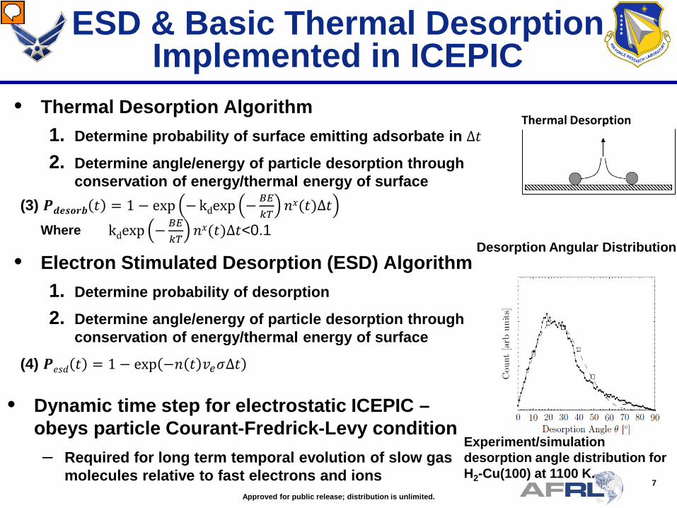
ESD & Basic Thermal Desorption Implemented in ICEPIC
Thermal Desorption
Experiment/simulation desorption angle distribution for H2-Cu(100) at 1100 K.
Desorption Angular Distribution
• Thermal Desorption Algorithm 1. Determine probability of surface emitting adsorbate in ∆𝑡𝑡
2. Determine angle/energy of particle desorption through conservation of energy/thermal energy of surface
(3) 𝑷𝑷𝒅𝒅𝒅𝒅𝒅𝒅𝒅𝒅𝒅𝒅𝒅𝒅 𝑡𝑡 = 1 − exp − kdexp −𝐵𝐵𝐵𝐵𝑘𝑘𝑇𝑇
𝑑𝑑𝑥𝑥(𝑡𝑡)∆𝑡𝑡
• Dynamic time step for electrostatic ICEPIC – obeys particle Courant-Fredrick-Levy condition – Required for long term temporal evolution of slow gas
molecules relative to fast electrons and ions
• Electron Stimulated Desorption (ESD) Algorithm 1. Determine probability of desorption
2. Determine angle/energy of particle desorption through conservation of energy/thermal energy of surface
(4) 𝑷𝑷𝑒𝑒𝑒𝑒𝑑𝑑 𝑡𝑡 = 1 − exp −𝑑𝑑 𝑡𝑡 𝑣𝑣𝑒𝑒𝜎𝜎∆𝑡𝑡
kdexp −𝐵𝐵𝐵𝐵𝑘𝑘𝑇𝑇
𝑑𝑑𝑥𝑥(𝑡𝑡)∆𝑡𝑡<0.1 Where

8 Approved for public release; distribution is unlimited.
Adsorption Algorithm Implemented in ICEPIC
𝑆𝑆 𝜃𝜃 = 𝑆𝑆0 1 − 𝜃𝜃 + 𝑆𝑆0∗(1 − 𝜃𝜃)(𝑞𝑞𝑚𝑚𝜃𝜃
1 − 𝑞𝑞𝑚𝑚𝜃𝜃)
𝑑𝑑𝑑𝑑(𝑡𝑡)𝑑𝑑𝑡𝑡
= 𝑆𝑆(𝑑𝑑 𝑡𝑡 )𝑝𝑝𝑁𝑁𝐴𝐴2𝜋𝜋𝑚𝑚𝑘𝑘𝑇𝑇
𝐴𝐴𝑁𝑁𝑠𝑠
1 − 𝜃𝜃(𝑡𝑡) − 𝑟𝑟𝑑𝑑𝑖𝑖 𝜃𝜃(𝑡𝑡))
1. Determine if gas molecule will adsorb to surface using eqn. (1)
2. Does gas collide with an adatom or with the surface. If R ≤ θ, where 0 ≤ R ≤ 1 then the gas molecule collides with an adatom, else the surface.
3. The gas molecule scatters using a scattering method or kernel. Utilizes the Cercignani-Lapis-Lord scattering kernel.
4. If the post-collisional normal translational energy Etr,n, of the gas molecule is sufficient to escape the Potential Energy Surface (PES) (Etr,n,≥ 2εLJ), then gas molecule scatters.
5. If the gas molecule cannot escape the PES, i.e. if Etot ≥ Eads and Ncolls ≤ 10, then return to Step 1 using post-collisional values. Otherwise, the gas molecule is adsorbed.
6. Temporally evolve adlayer coverage using eq. 2 εLJ is the Lennard-Jones potential well energy for adatom
Probability of particle adsorbing to the surface
Temporal evolution of adlayer coverage using the state space
(1)
(2) Bentley, Brook I., Greendyke, R. B. “New method of calculating adsorption and scattering for Xe-Pt(111) using Direct Simulation Monte Carlo techniques”, Phys. Of Plasmas
Simulation/experiment comparison for adsorption for Xe-Pt(111) at 800 K
Lobular Particle scattering from the surface
𝜃𝜃 - Fraction of Adlayer Coverage

9 Approved for public release; distribution is unlimited.
• ICEPIC & analytic results compared to non-thermal ESD outgassing in experiment – Electron beam pulse width 10 ms & 2 keV electrons – Cu surface with H2 adlayer – H2 is outgassed quickly
ICEPIC Simulation and Comparison to Experiment
Cross-section for desorption 3.5x10⁻²¹ cm2 (Menzel and Gomer)
• Analytic, ICEPIC, & experiment show increase in H2 pressure in the cell to 7.0x10⁻⁹ Torr
Experiment
ESD generated H2
ICEPIC Sim of e- Beam Hitting Surface
e-
Velocity (m/s)
Velocity (m/s)
ICEPIC
• A = -𝐽𝐽𝑒𝑒𝜎𝜎 + 𝐶𝐶𝑃𝑃𝑔𝑔𝑀𝑀𝑇𝑇
• B=−𝑘𝑘𝑑𝑑exp −𝐵𝐵𝐵𝐵
𝑘𝑘𝑇𝑇− 𝐶𝐶𝑃𝑃𝑔𝑔
𝑛𝑛𝑎𝑎 𝑀𝑀𝑇𝑇 𝑑𝑑 𝑡𝑡 =
Aexp 𝐴𝐴 ∗ 𝑡𝑡𝐵𝐵 exp 𝐴𝐴 ∗ 𝑡𝑡 + 1
+ 𝑑𝑑(0)
Analytic
H2 P
ress
ure
(Tor
r)
Time (s) Thermal Desorption Maintains pressure
Mostly ESD

10 Approved for public release; distribution is unlimited.
60 keV e- gun RGA(3)
Simulated anode
RGA
Anode load/lock
Surface Analysis • AES • XPS • UPS • EELS
Anode Materials Characterization System • High energy e- gun (CW or pulsed) • Surface characterization of anodes
(Before & after e- bombardment) • Measure TOF distribution of desorbed species (H2, CO) (Translational temperature) • Photoelectron-photoion coincidence (PEPICO) spectrometer (Vibrational state distribution of desorbed species)
PEPICO spectrometer
PEPICO spectrometer
Anode Material Characterization System (AMCS)
• Collaborative AFOSR LRIR w/ RXP & RDH Experiment – Novel nanomaterials for High
Power Density, Nonequilibrium Environments of DE Weapons
– Verify ICEPIC simulations against experiment
– Design materials that mitigate neutral outgassing/vacuum breakdown in HPM sources

11 Approved for public release; distribution is unlimited.
Hybrid Boltzmann/PIC
• Objective: Integrate a Boltzmann transport model into the particle in cell Monte Carlo collision (PIC/MCC) method
• Tasks Completed:
– Implemented a finite difference time domain solver with PIC/MCC
– Implemented a Boltzmann Equation solver:
• Assumed the solution could be expanded into a spherical harmonic series (Legendre Polynomials)
• Converted equation to a system of PDE’s and used finite-difference approximations and an ODE integrator to step forward in time
– Combined the separate solvers into one code.
• Remaining Tasks/Challenges:
– Establish weightings to allow for accurate combination of separate methods to simulate evolution of particle distribution functions.
– Use weightings to complete the hybrid Boltzmann/MCC code

12 Approved for public release; distribution is unlimited.
Hybrid Boltzmann/PIC Results
• Good agreement between Boltzmann Equation solver and PIC/MCC code.

13 Approved for public release; distribution is unlimited.
Space Charge Limited Emission
• Want analytic results to test particle-in-cell emission
• Child-Langmuir law in 1-D, Langmuir-Blodgett in 2-D/3-D
• Original Child-Langmuir/Langmuir-Blodgett expressions not relativistically correct
• Find closed form relativistic expression in 1-D
• Transform relativistic equations in 2-D/3-D for application of an Ordinary Differential Equation (ODE) integrator
• Compare results to ICEPIC
• Comparison is favorable, but convergence is slow (as expected)

14 Approved for public release; distribution is unlimited.
Geometry
• Separation of variables applies
– Parallel plates in 1-D
– Coaxial cylinders in 2-D
– Concentric spheres in 3-D
• Cathode at 𝒅𝒅𝒄𝒄 = 𝒅𝒅𝟏𝟏 or 𝒅𝒅𝟐𝟐 and potential 𝑽𝑽 = 𝟎𝟎
• Anode at 𝒅𝒅𝒂𝒂 = 𝒅𝒅𝟐𝟐 or 𝒅𝒅𝟏𝟏(opposite cathode) and potential 𝑽𝑽 = 𝑽𝑽𝟎𝟎 > 𝟎𝟎
• Space charge limit implies derivative of 𝑽𝑽 is zero at the cathode
𝒛𝒛 = 𝒅𝒅𝟏𝟏 𝒛𝒛 = 𝒅𝒅𝟐𝟐
𝒛𝒛 𝒅𝒅
𝒅𝒅𝟏𝟏 𝒅𝒅𝟐𝟐

15 Approved for public release; distribution is unlimited.
Parallel Plates
• R.J. Umstattd, C.G.Carr, C.L. Frezen, J.W.Luginsland, and Y.Y.Lau, “A Simple Derivation of Child-Langmuir Space Charge Limited Emission Using Vacuum Capacitance,” Am J Phys, Vol 73, No 2, Feb 2005.
• 𝒅𝒅𝟐𝟐𝑽𝑽𝒅𝒅𝒛𝒛𝟐𝟐
= 𝑱𝑱𝟏𝟏𝟏𝟏 𝑽𝑽𝒅𝒅+𝒎𝒎𝒄𝒄𝟐𝟐
𝝐𝝐𝒄𝒄 𝑽𝑽𝒅𝒅 𝑽𝑽𝒅𝒅+𝟐𝟐𝒎𝒎𝒄𝒄𝟐𝟐
• 𝑱𝑱𝟏𝟏𝟏𝟏 = 𝟒𝟒𝟗𝟗𝝐𝝐 𝟐𝟐𝒅𝒅
𝒎𝒎𝑽𝑽𝟎𝟎
𝟑𝟑𝟐𝟐
𝒅𝒅𝟐𝟐 𝟐𝟐𝑭𝑭𝟏𝟏𝟏𝟏𝟒𝟒
, 𝟑𝟑𝟒𝟒
; 𝟕𝟕𝟒𝟒
;− 𝑽𝑽𝟎𝟎𝒅𝒅𝟐𝟐𝒎𝒎𝒄𝒄𝟐𝟐
𝟐𝟐
• Expression is identical to classical Child-Langmuir with addition of the hypergeometric function

16 Approved for public release; distribution is unlimited.
• Cylinders: 𝒅𝒅 𝒅𝒅𝟐𝟐𝑽𝑽𝒅𝒅𝒅𝒅𝟐𝟐
+ 𝒅𝒅𝑽𝑽𝒅𝒅𝒅𝒅
= 𝑱𝑱𝟐𝟐𝟏𝟏𝟐𝟐𝝅𝝅𝝐𝝐𝒄𝒄
𝑽𝑽𝒅𝒅+𝒎𝒎𝒄𝒄𝟐𝟐
𝑽𝑽𝒅𝒅(𝑽𝑽𝒅𝒅+𝟐𝟐𝒎𝒎𝒄𝒄𝟐𝟐)
• Spheres: 𝒅𝒅𝟐𝟐 𝒅𝒅𝟐𝟐𝑽𝑽𝒅𝒅𝒅𝒅𝟐𝟐
+ 𝟐𝟐𝒅𝒅 𝒅𝒅𝑽𝑽𝒅𝒅𝒅𝒅
= 𝑰𝑰𝟑𝟑𝟏𝟏𝟒𝟒𝝅𝝅𝝐𝝐𝒄𝒄
𝑽𝑽𝒅𝒅+𝒎𝒎𝒄𝒄𝟐𝟐
𝑽𝑽𝒅𝒅(𝑽𝑽𝒅𝒅+𝟐𝟐𝒎𝒎𝒄𝒄𝟐𝟐)
• Problem: 𝒅𝒅𝟐𝟐𝑽𝑽𝒅𝒅𝒅𝒅𝟐𝟐
→ ∞ as 𝒅𝒅 → 𝒅𝒅𝒄𝒄
• Solution: transform equations with 𝚿𝚿 = 𝑽𝑽𝟑𝟑 𝟐𝟐⁄
• Cylinders: 𝒅𝒅𝟐𝟐𝚿𝚿𝒅𝒅𝒅𝒅𝟐𝟐
= 𝟑𝟑𝑱𝑱𝟐𝟐𝟏𝟏𝟒𝟒𝝅𝝅𝝐𝝐𝒄𝒄𝒅𝒅
𝚿𝚿𝟐𝟐 𝟑𝟑⁄ 𝒅𝒅+𝒎𝒎𝒄𝒄𝟐𝟐
𝒅𝒅 𝚿𝚿𝟐𝟐 𝟑𝟑⁄ 𝒅𝒅+𝟐𝟐𝒎𝒎𝒄𝒄𝟐𝟐− 𝟏𝟏
𝒅𝒅𝒅𝒅𝚿𝚿𝒅𝒅𝒅𝒅
+ 𝟏𝟏𝟑𝟑𝚿𝚿
𝒅𝒅𝚿𝚿𝒅𝒅𝒅𝒅
𝟐𝟐
• Spheres: 𝒅𝒅𝟐𝟐𝚿𝚿𝒅𝒅𝒅𝒅𝟐𝟐
= 𝟑𝟑𝑰𝑰𝟑𝟑𝟏𝟏𝟖𝟖𝝅𝝅𝝐𝝐𝒄𝒄𝒅𝒅𝟐𝟐
𝚿𝚿𝟐𝟐 𝟑𝟑⁄ 𝒅𝒅+𝒎𝒎𝒄𝒄𝟐𝟐
𝒅𝒅 𝚿𝚿𝟐𝟐 𝟑𝟑⁄ 𝒅𝒅+𝟐𝟐𝒎𝒎𝒄𝒄𝟐𝟐− 𝟐𝟐
𝒅𝒅𝒅𝒅𝚿𝚿𝒅𝒅𝒅𝒅
+ 𝟏𝟏𝟑𝟑𝚿𝚿
𝒅𝒅𝚿𝚿𝒅𝒅𝒅𝒅
𝟐𝟐
Coaxial Cylinders/Concentric Spheres

17 Approved for public release; distribution is unlimited.
Results
• Results of the relativistic calculations compared to classical and ultra-relativistic approximations
• Largest error at voltage where the approximations cross

18 Approved for public release; distribution is unlimited.
Results
• ICEPIC grid convergence for inward directed current
• Emission algorithm converges slowly

19 Approved for public release; distribution is unlimited.
Conclusion
• Work on non-linear material modeling largely complete
• Initial implementation of surface chemistry/outgassing model is now in ICEPIC
• Hybrid Boltzmann/MCC code is in progress
• Work with space charge limited emission allows analytic validation of ICEPIC emission models