Improved performance of Ag-nanoparticle-decorated TiO2 nanotube arrays in Li-ion batteries
6
Journal of the Korean Physical Society, Vol. 63, No. 9, November 2013, pp. 1809∼1814 Improved Performance of Ag-nanoparticle-decorated TiO 2 Nanotube Arrays in Li-ion Batteries Syed Atif Pervez, Umer Farooq, Adnan Yaqub and Chil-Hoon Doh ∗ Korea Electro-technology Research Institute, Changwon 642-120, Korea and Electrical Functionality Material Engineering (KERI Campus), University of Science and Technology, Daejeon 305-333, Korea Doohun Kim, Seongju Sim, Minji Hwang, Jeong-Hee Choi and You-Jin Lee Korea Electro-technology Research Institute, Changwon 642-120, Korea (Received 29 May 2013, in final form 18 June 2013) The present work investigates the electrochemical response of silver nanoparticle (Ag-NP)- decorated TiO2 nanotube (NT) layers as an anode material for a lithium-ion battery. Self-organized nanotube layers with a thickness of approximately 1 µm and a diameter of approximately 100 nm were grown by anodization of Ti in a fluoride-containing aqueous electrolyte. Ag NPs (av- erage particle size of ∼10 nm) were deposited both inside and outside the nanotube geometry in a well-distributed manner through a simple and efficient photocatalytic reduction process. The morphology and the chemical composition of the resulting materials were characterized by using field-emission scanning electron microscopy (FE-SEM), X-ray diffraction (XRD) and energy disper- sive X-ray spectroscopy (EDX). Our results show that the TiO2 NT layers decorated with Ag NPs had a superior electrochemical response in terms of charge/discharge capacity, rate capability, cyclic performance and columbic efficiency. The enhanced performance is attributed to the improved elec- tronic and ionic conductivity, obtained by providing highly conductive paths to electrons flowing through a well-distributed Ag NPs deposition on the walls of the highly-oriented NTs. PACS numbers: 82.45.+z, 84.60.Dn, 81.65.Mg Keywords: Nanoparticle, TiO 2 nanotube array, Anodization, Li-ion battery, Anode DOI: 10.3938/jkps.63.1809 I. INTRODUCTION The Li-ion battery (LIB) has shown great potential to fulfill the growing energy demand for hybrid electric vehi- cles, smart grid applications and portable electronic de- vices due to its advantages of high power and energy den- sity, long cycle life and structural stability. The current LIB industry has been primarily dominated by graphite as an anode material due to its good cyclic performance, safety features and abundant availability [1,2]. However, graphite has certain limitations, such as low rate ability, metallic-lithium dendrite formation due to its low lithia- tion potential (∼0V vs. Li/Li+) and co-intercalation of solvated ions in the structure [3]. In a quest to overcome the aforementioned limitations of graphite, the focus of the current research is to improve its performance either by introducing innovative variations into its structure or completely replacing it with other more suitable anode materials. Recently, TiO 2 has attracted enormous attention as ∗ E-mail: [email protected]; Tel: +82-55-280-1662 a potential candidate to replace graphite. The advan- tages of TiO 2 are higher Li insertion potential (∼1.7 V vs. Li/Li+), good capacity retention, low self-discharge, abundant availability and environmental benignity [4– 8]. In order to obtain higher capacity, researchers have primarily focused on developing and investigating 1- dimensional nanostructures of TiO 2 , such as nanotubes [9, 10], nanoparticles [11, 12], nanowires [13] and meso- porous structures [14, 15], with the aim to reduce the transport path of Li ions and electrons and to increase the contact area between the electrode and the elec- trolyte. Among these nanostructures, TiO 2 nanotubes (NTs) synthesized through anodization have attracted much attention. Some early reports [9,16] have shown successful application of anodized TiO 2 NTs as anode materials. Ever since then, a great deal of research has been undertaken on improving the electrochemical performance of TiO 2 NTs. Various approaches such as doping and designing composites have been adopted [17–19]. One such approach is surface modification, in which another element is introduced to interact with the transition-metal ion on the crystal’s surface. This ap- -1809-
Transcript of Improved performance of Ag-nanoparticle-decorated TiO2 nanotube arrays in Li-ion batteries

Journal of the Korean Physical Society, Vol. 63, No. 9, November 2013, pp. 1809∼1814
Improved Performance of Ag-nanoparticle-decorated TiO2 Nanotube Arraysin Li-ion Batteries
Syed Atif Pervez, Umer Farooq, Adnan Yaqub and Chil-Hoon Doh∗
Korea Electro-technology Research Institute, Changwon 642-120, Korea andElectrical Functionality Material Engineering (KERI Campus),University of Science and Technology, Daejeon 305-333, Korea
Doohun Kim, Seongju Sim, Minji Hwang, Jeong-Hee Choi and You-Jin Lee
Korea Electro-technology Research Institute, Changwon 642-120, Korea
(Received 29 May 2013, in final form 18 June 2013)
The present work investigates the electrochemical response of silver nanoparticle (Ag-NP)-decorated TiO2 nanotube (NT) layers as an anode material for a lithium-ion battery. Self-organizednanotube layers with a thickness of approximately 1 µm and a diameter of approximately 100nm were grown by anodization of Ti in a fluoride-containing aqueous electrolyte. Ag NPs (av-erage particle size of ∼10 nm) were deposited both inside and outside the nanotube geometry ina well-distributed manner through a simple and efficient photocatalytic reduction process. Themorphology and the chemical composition of the resulting materials were characterized by usingfield-emission scanning electron microscopy (FE-SEM), X-ray diffraction (XRD) and energy disper-sive X-ray spectroscopy (EDX). Our results show that the TiO2 NT layers decorated with Ag NPshad a superior electrochemical response in terms of charge/discharge capacity, rate capability, cyclicperformance and columbic efficiency. The enhanced performance is attributed to the improved elec-tronic and ionic conductivity, obtained by providing highly conductive paths to electrons flowingthrough a well-distributed Ag NPs deposition on the walls of the highly-oriented NTs.
PACS numbers: 82.45.+z, 84.60.Dn, 81.65.MgKeywords: Nanoparticle, TiO2 nanotube array, Anodization, Li-ion battery, AnodeDOI: 10.3938/jkps.63.1809
I. INTRODUCTION
The Li-ion battery (LIB) has shown great potential tofulfill the growing energy demand for hybrid electric vehi-cles, smart grid applications and portable electronic de-vices due to its advantages of high power and energy den-sity, long cycle life and structural stability. The currentLIB industry has been primarily dominated by graphiteas an anode material due to its good cyclic performance,safety features and abundant availability [1,2]. However,graphite has certain limitations, such as low rate ability,metallic-lithium dendrite formation due to its low lithia-tion potential (∼0 V vs. Li/Li+) and co-intercalation ofsolvated ions in the structure [3]. In a quest to overcomethe aforementioned limitations of graphite, the focus ofthe current research is to improve its performance eitherby introducing innovative variations into its structure orcompletely replacing it with other more suitable anodematerials.
Recently, TiO2 has attracted enormous attention as
∗E-mail: [email protected]; Tel: +82-55-280-1662
a potential candidate to replace graphite. The advan-tages of TiO2 are higher Li insertion potential (∼1.7 Vvs. Li/Li+), good capacity retention, low self-discharge,abundant availability and environmental benignity [4–8]. In order to obtain higher capacity, researchers haveprimarily focused on developing and investigating 1-dimensional nanostructures of TiO2, such as nanotubes[9, 10], nanoparticles [11, 12], nanowires [13] and meso-porous structures [14, 15], with the aim to reduce thetransport path of Li ions and electrons and to increasethe contact area between the electrode and the elec-trolyte. Among these nanostructures, TiO2 nanotubes(NTs) synthesized through anodization have attractedmuch attention. Some early reports [9, 16] have shownsuccessful application of anodized TiO2 NTs as anodematerials. Ever since then, a great deal of researchhas been undertaken on improving the electrochemicalperformance of TiO2 NTs. Various approaches suchas doping and designing composites have been adopted[17–19]. One such approach is surface modification, inwhich another element is introduced to interact with thetransition-metal ion on the crystal’s surface. This ap-
-1809-
-1810- Journal of the Korean Physical Society, Vol. 63, No. 9, November 2013
proach is different from doping where the element entersthe lattice and substitutes for the transition-metal ion.Surface modification of TiO2 NTs done through loadingof noble-metal nanoparticles is a well-studied and famoustechnique in the field of photocatalysis and photochem-istry [20–22]. However, such an approach has rarely beenused in the field of LIBs to study the electrochemical re-sponse of TiO2 NT- based anode materials.
In this work, we report that loading of Ag NPs into an-odized TiO2 nanotube arrays significantly enhances theelectrochemical performance when used as an anode ma-terial for Li-ion battery. We have selected Ag nanoparti-cles because of their strong substrate coupling effect, ex-cellent electron conductivity and lower cost. The struc-ture has many advantages: (1) an improved electronicconductivity as Ag NPs on the walls of the NTs providehigh conductivity paths for electron flow in the mate-rial, (2) the high porosity of anodized NTs which ex-hibit a greater Li-ion packing density and an enhancedcontact area between the electrode and the electrolyte,(3) vectorial charge transfer along the direction of thehighly-oriented nanotubes, and (4) use of Ti as a currentcollector, which avoids conductive carbon and binder inthe electrode, and makes the synthesis process simplerand the anode material more stable.
II. EXPERIMENTAL
Initially, Ti foils (0.1 mm thickness, 99.5% purity,Nilaco) were degreased by sonicating in acetone andethanol for 20 minutes each and were then rinsed withdeionized water. To prepare self-organized NT layers,electrochemical anodization was carried out in a two-electrode cell configuration following the method re-ported by Macak et al. [23]. Ti metal was used as work-ing electrode, and platinum mesh served as a counterelectrode. An aqueous electrolyte, a mixture of glyceroland water (50 : 50 vol%) + 0.27-M NH4F, was usedduring the experiment. The anodization was conductedusing a high-voltage potentiostat (OPS-22101, ODA, Ko-rea) to apply a constant voltage of 20 V for 120 minutes.The obtained samples were rinsed in ethanol and dried inan oven. All the experiments were carried out at roomtemperature. After anodization, the samples were an-nealed to convert them from amorphous to anatase andrutile crystalline phases of TiO2 by using a furnace (XY-1400 S, Hantech, Korea) with heating and cooling ratesof 10 ◦C/min. The annealing temperature was 450 ◦Cfor anatase phase and 700 ◦C for the rutile phase, andthe time duration was 1 hour in each case.
Ag NPs were loaded on nanotube layers through a pho-tocatalytic reduction process reported elsewhere [20]. Inthe first step, the anodized samples were initially soakedin a 1-M AgNO3 solution for 1 hour, then rinsed withDI water and finally dried in open atmosphere at roomtemperature. In the second step, photocatalytic decom-
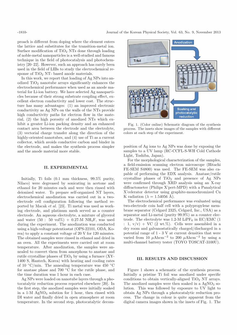
Fig. 1. (Color online) Schematic diagram of the synthesisprocess. The insets show images of the samples with differentcolors at each step of the experiment.
position of Ag ions to Ag NPs was done by exposing thesamples to a UV lamp (RC-CCFL-S-WH Cold CathodeLight, Toshiba, Japan).
For the morphological characterization of the samples,a field-emission scanning electron microscope (HitachiFE-SEM S4800) was used. The FE-SEM was also ca-pable of performing the EDX analysis. Anatase/rutilecrystalline phases of TiO2 and presence of Ag NPswere confirmed through XRD analysis using an X-raydiffractometer (Philips X’pert-MPD) with a PanalyticalX’celerator detector using graphite-monochromized CuK radiation (λ = 1.54056 A).
The electrochemical performance was evaluated usingtwo-electrode coin half cell with a polypropylene mem-brane separator (Celgard 2325, Celgard, Inc., USA) as aseparator and Li-metal (purity 99.9%) as a counter elec-trode. The electrolyte was 1.2-M LiPF6 in EC/EMC (1: 1, v/v) + VC (2 wt.%). Cells were assembled in adry room and galvanostatically charged/discharged in apotential range of 1 - 3 V at current densities that werevaried from 10 µAhcm−2 to 200 µAhcm−2 by using amulti-channel battery tester (TOYO TOSCAT-3100U).
III. RESULTS AND DISCUSSION
Figure 1 shows a schematic of the synthesis process.Initially a pristine Ti foil was anodized under specificconditions to obtain vertically-aligned TiO2 NT arrays.The anodized samples were then soaked in a AgNO3 so-lution. This was followed by exposure to UV light toobtain Ag NPs through a photocatalytic reduction pro-cess. The change in colour is quite apparent from thedigital camera images shown in the insets of Fig. 1. The

Improved Performance of Ag-nanoparticle-decorated· · · – Syed Atif Pervez et al. -1811-
Fig. 2. SEM images of the self-organized amorphous TiO2
nanotube layers formed by the anodization of Ti-metal inan aqueous electrolyte: (a, b) Top and cross-sectional viewswithout Ag NPs, and (c, d) Top and cross-sectional viewswith Ag NPs.
silver color of pristine Ti foil changed to light brown af-ter the anodization step and then to dark brown aftersoaking and exposure to UV light.
In Fig. 2, the top and the cross-sectional FE-SEM im-ages of amorphous NTs with and without Ag NP load-ing are shown. Electrochemical anodization leads to thegrowth of vertically- aligned TiO2 nanotubular struc-tures perpendicular to the Ti substrates. The diame-ter of the NTs was ∼100 nm while the length was ∼1m. An aqueous electrolyte, containing glycerol and wa-ter in equal volume percentage (50 : 50) with NH4F,was deliberately chosen to ensure NTs with wider diam-eters and no top layer [23]. The absence of the top layerand the wider diameter was helpful in allowing a greaternumber of Ag NPs to penetrate and be loaded into theNTs, as shown in Figs. 2 (c) and (d). A simple andcost-effective photocatalytic reduction method was thenadopted to deposit Ag NPs (average particle size of ∼10nm) both inside and outside the geometry of the NTs.The nanoparticles showed strong attachment to the sur-faces of the NTs without any agglomeration. It’s worthmentioning here that the size of Ag NPs strongly de-pended on the UV intensity and irradiation time [20,24].Therefore, in our experiment, we have kept both param-eters constant by following an optimized UV irradiationprocess. However, further study may be carried out infuture work to identify the effect of Ag NP size on thedevice performances.
The as-prepared amorphous NT arrays were annealedin an air furnace at 450 ◦C to obtain the anatase crys-talline phase and at 700 ◦C to obtain the rutile crys-talline phase. The heat treatment duration was 1 hourin each case. Figure 3 shows the XRD patterns of (a)
Fig. 3. (Color online) XRD spectra of (a) amorphous, (b)anatase, and (c) rutile TiO2 nanotube layers after loading ofAg NPs. The diffraction peak notations A, R, T and Ag cor-respond to anatase, rutile, titanium and silver, respectively.(d) EDX spectra for the sample after Ag-NP loading.
amorphous, (b) anatase and (c) rutile phases after load-ing with Ag NPs. The diffraction peak notations A, R,T and Ag correspond to anatase, rutile, titanium and sil-ver, respectively. The results show that the as-preparedsample is in an amorphous phase because there are nocharacteristic XRD peaks for crystalline TiO2. However,after annealings at 450 ◦C and 700 ◦C the correspondinganatase and rutile peaks can be observed. Apart fromthe anatase and the rutile peaks, all the samples show ad-ditional peaks which corresponds to the Ag NPs. Figure3(d) shows the EDX analysis of the as-prepared sample

-1812- Journal of the Korean Physical Society, Vol. 63, No. 9, November 2013
Fig. 4. (Color online) 1st, 2nd and 5th galvanostatic charge/discharge cycles (a) amorphous NTs with Ag NPs, (b), anataseNTs with Ag NPs, (c) amorphous NTs without Ag NPs, and (d) rutile NTs with Ag NPs from 1.0 to 3.0 V at a current densityof 10 µAhcm−2.
after loading with Ag NPs. A clear silver peak is ob-served in the EDX spectrum which further confirms thepresence of Ag NPs inside the structure.
In order to evaluate the performance of Ag NP-decorated TiO2 NT arrays, we investigated the elec-trochemical response of its amorphous, anatase andrutile phases in terms of Li intercalation and de-intercalation. In this work, for the sake of clarity, atypical charge/discharge cycle is defined as 1) a chargecycle, during which Li insertion occurs until a lower limitvoltage (1 V) is reached and 2) a discharge cycle, inwhich Li extraction occurs until a cut-off voltage (3 V)is reached. Figure 4 shows the 1st, 2nd and 5th galvanos-tatic charge/discharge cycles of (a) amorphous NTs withAg NPs, (b), anatase NTs with Ag NPs, (c) amorphousNTs without Ag NPs, and (d) rutile NTs with Ag NPsfrom 1.0 to 3.0 V at a current density of 10 µAhcm−2.Anodization conditions for all the samples were kept thesame i.e., 60 V and 2 hours. From the results, it is quiteclear that the initial charge/discharge capacity of amor-phous Ag-NP-decorated NTs is significantly higher thanit’s for all the other samples. Also, a voltage plateau
at around 1.1 V is observed during the 1st charge cy-cle of the amorphous samples which cannot be found inthe anatase and the rutile samples. The voltage plateauis responsible for the high irreversible capacity which isin agreement with a recently published work [25]. Thehigher specific capacity in the case of amorphous NTs(Fig. 4 (a) and 4(c)) indicates that more lithium ionsper TiO2 can be accommodated in comparison to eitherthe anatase or the rutile structures (Fig. 4(b) and 4(d)). These findings are consistent with those of somepreviously-reported works [13, 26]. Therefore, due totheir enhanced capacity we focused on amorphous NTsfor further experiments related to the study of the im-pact of Ag-NP loading on the performance of the anodematerial. A comparative analysis of TiO2 NTs with AgNPs (Fig. 4a) and without Ag NPs (Fig. 4c) clearlyshows the enhanced anode capacity in the former case.Ag NPs are responsible for the enhanced surface elec-tron transfer rate in the TiO2 NTs, so such an increasein capacity is observed.
In order to further examine the role of Ag NPs, wehave conducted rate capability tests of the amorphous

Improved Performance of Ag-nanoparticle-decorated· · · – Syed Atif Pervez et al. -1813-
Fig. 5. Rate capability test for TiO2 NT arrays with andwithout Ag NPs. The specific discharge capacities were eval-uated at various current densities ranging from 10 µAhcm−2
to 200 µAhcm−2.
samples. Figure 5 shows a comparison of the dischargecapacities evaluated at various current densities rangingfrom 10 µAhcm−2 to 200 µAhcm−2. A significant in-crease in the specific capacity of TiO2 NTs with Ag NPsis observed at various scan rates and is attributed to theenhanced electron transfer rate due to the presence ofthe Ag NPs. It is interesting to note that in the initialfew cycles, there is a drastic decrease in the capacity forboth the samples. This variation in capacity is possiblydue to the side reactions with the physically-adsorbedwater molecules in the TiO2 NTs [26] and disappears assoon as the residual water is consumed in the followingcycles. A relatively stable capacity value is, therefore,retained afterwards at all the scan rates. Also, a goodcapacity recovery of ∼96% is observed at 10 µAhcm−2
for NTs decorated with Ag NPs. This suggests a higherstructure stability and robustness of the Ag-NP-basedanode materials.
The results of cyclic performance test are shown in Fig.6. The test was carried out immediately after the experi-ment shown in Fig. 5 at a current density of 10 µAhcm−2
for 100 cycles. From the figure, it is apparent that thereversible capacity retention for Ag-NP-decorated NTsis quite exceptional as they demonstrate almost no ca-pacity loss between the 2nd and the 100th cycle. Also,the columbic efficiency was around 98% and showed anexcellent reversible charge-discharge behavior.
IV. CONCLUSION
Ag-NP-decorated anodized TiO2 nanotube layers withdifferent crystalline phases were prepared and success-fully employed as LIB anodes. An aqueous electrolyte
Fig. 6. Cyclic performance and columbic efficiency of TiO2
NT arrays with and without Ag NPs. The capacity graphsare obtained at a current density of 10 µAhcm−2 immediatelyafter the rate capability test.
was used for anodization to obtain geometrically suit-able NTs. Ag-NP loading was done by soaking the NTlayers in a AgNO3 solution, followed by photocatalyticreduction of Ag ions to Ag NPs. The results showeda superior electrochemical response of Ag-NP-decoratedTiO2 NTs layers, especially in the amorphous crystallinephase. The enhancement in performance was attributedto the improved electronic conductivity offered by theAg NPs, which had been deposited in a well-distributedmanner on the walls of the TiO2 NTs.
ACKNOWLEDGMENTS
The authors would like to acknowledge the financialsupport from the Korea Government, the Ministry ofKnowledge Economy.
REFERENCES
[1] T. D. Tran, J. H. Feikert, X. Song and K. Kinoshita, J.Electrochem. Soc. 142, 3297 (1995).
[2] D. Aurbach, Y. Ein-Eli, O. Chusid, Y. Carmeli, M. Babaiand H. Yamin, J. Electrochem. Soc. 3, 603 (1994).
[3] M. Winter and J. O. Besenhard, Electrochim. Acta 45,31 (1999).
[4] M. Wagenaker, A. P. M. Kentgens and F. M. Mulder,Nature 418, 397 (2002).
[5] P. G. Bruce, B. Scrosati and J. M. Tarascon, Angew.Chem. Int. Ed. 47, 2930 (2008).
[6] A. N. Jansen, A. J. Kahaian, K. D. Kepler, P. A. Nel-son, K. Amine, D. W. Dees, D. R. Vissers and M. M.Thackeray, J. Power Sources 5, 902 (1999).
[7] A. R. Armstrong, G. Armstrong, J. Canales and P. G.Bruce, J. Power Sources 146, 501 (2005).

-1814- Journal of the Korean Physical Society, Vol. 63, No. 9, November 2013
[8] M. A. Reddy, M. S. Kishore, V. Pralong, V. Caignaert,U. V. Varadaraju and B. Raveu, Electrochemistry Com-mun. 8, 1299 (2006).
[9] G. F. Ortiza, I. Hanzua, P. Knauth, P. Lavela, J. L.Tiradob and T. Djenizian, Electrochem. Acta 54, 4262(2009).
[10] X. P. Gao, Y. Lan, H. Y. Zhu, J. W. Liu, Y. P. Ge, F.Wu and D. Y. Song, Electrochem. Solid-State Lett. 8,A26 (2005).
[11] C. H. Jiang, I. Honma, T. Kudo and H. S. Zhou, Elec-trochem. Solid-State Lett. 10, A127 (2007).
[12] C. H. Jiang, I. Honma, T. Kudo and H. S. Zhou, J. PowerSources 166, 239 (2007).
[13] A. R. Armstrong, G. Armstrong, J. Canales, R. Garcıaand P. G. Bruce, Adv. Mater. 17, 862 (2005).
[14] Y. G. Guo, Y. S. Hu, W. Sigle and J. Maier, Adv. Mater.19, 2087 (2007).
[15] Z. Ali, S. N. Cha, J. I. Sohn, I. Shakir, C. Yan, J. M.Kim and D. Kang, J. Mater. Chem. 22, 17625 (2012).
[16] G. F. Ortiz, I. Hanzu, T. Djenizian, P. Lavela, J. L.Tirado and P. Knauth, Chem. Mater. 21, 63 (2009).
[17] N. A. Kyeremateng, V. Hornebecq, P. Knauth and T.
Djenizian, Electrochimia Acta 62, 192 (2012).[18] N. A. Kyeremateng, F. Vacandio, M. T. Sougrati, H.
Martinez, J. C. Jumas, P. Knauth and T. Djenizian, J.Power Sources 224, 269 (2013).
[19] G. F. Ortiz, I. Hanzu, P. Knauth, P. Lavela, J. L. Tiradoand T. Djenizian, Electrochem. Solid-State Lett. 12,A186 (2009).
[20] I. Paramasivam, J. M. Macak, A. Ghicov and P.Schmuki, Chemical Physics Lett. 445, 233 (2007).
[21] D. B. Ingram and S. Linic, J. American Chem. Soc. 133,5202 (2011).
[22] I. Paramasivam, J. M. Macak, A. Ghicov and P. SchmukiElectrochemistry Comm. 10, 71 (2008).
[23] J. M. Macak and P. Schmuki, Electrochem. Acta 52,1258 (2006).
[24] K Chen, X. Feng, R. Hu, Y. Li, K. Xie and H. Gu, J.Alloys Comp. 554, 72 (2013)
[25] B. Zhonghe, M. P. Paranthaman, B. Guo, X. G. Sun andS. Dai, J. Power Sources 222, 461 (2013).
[26] W. H. Ryu, D. H. Nam, Y. S. Ko, R. H. Kim and H. S.Kwon, Electrochem. Acta 61, 19 (2012).


![Heterostructured ZnFe2O4/Fe2TiO5/TiO2 Composite Nanotube … · 2017-11-17 · hydrogen production via water splitting [8–10], photocat-alytic degradation of organic pollutants](https://static.fdocuments.net/doc/165x107/5e680e512e67a35e30098bf0/heterostructured-znfe2o4fe2tio5tio2-composite-nanotube-2017-11-17-hydrogen-production.jpg)