
Improved Open Photoacoustic Helmholtz Cell
9
Int J Thermophys DOI 10.1007/s10765-013-1479-y Improved Open Photoacoustic Helmholtz Cell Tomasz Starecki · Antonina Geras Received: 11 April 2013 / Accepted: 19 June 2013 © The Author(s) 2013. This article is published with open access at Springerlink.com Abstract This paper presents the design of an open photoacoustic Helmholtz cell in which high acoustic volumes with quarter-wave ducts act as high-impedance separa- tors between the main Helmholtz cell structure and the exterior. As a result, penetration of the external acoustic noise into the cell was substantially reduced in comparison to earlier open Helmholtz cell designs. Although the presented cell is not windowless, the photoacoustic background signal resulting from the absorption of the light by the windows is significantly lower in comparison to standard Helmholtz cells. Such an effect was obtained by locating the windows not at the relatively small sample cav- ity, but at the acoustic buffers, for which the volumes are two orders of magnitude higher. The proposed cell is dedicated for gas or liquid measurements, and its design allows for constant flow of the fluid. Hence, it can be used in continuous, real-time photoacoustic measurements. Keywords Acoustic buffers · External acoustic noise attenuation · Helmholtz resonator · Open photoacoustic cell 1 Introduction The amplitude of the photoacoustic signal depends on many factors, but in particular it varies inversely to the light modulation frequency, f , and volume of the cell, V , and is proportional to the quality factor, Q, of the cell (if the light is modulated with a frequency at which the acoustic resonance of the cell occurs) [1]: T. Starecki (B ) · A. Geras Institute of Electronic Systems, Warsaw University of Technology, Nowowiejska 15/19, 00-665 Warsaw, Poland e-mail: [email protected] 123
Transcript of Improved Open Photoacoustic Helmholtz Cell

Int J ThermophysDOI 10.1007/s10765-013-1479-y
Improved Open Photoacoustic Helmholtz Cell
Tomasz Starecki · Antonina Geras
Received: 11 April 2013 / Accepted: 19 June 2013© The Author(s) 2013. This article is published with open access at Springerlink.com
Abstract This paper presents the design of an open photoacoustic Helmholtz cell inwhich high acoustic volumes with quarter-wave ducts act as high-impedance separa-tors between the main Helmholtz cell structure and the exterior. As a result, penetrationof the external acoustic noise into the cell was substantially reduced in comparison toearlier open Helmholtz cell designs. Although the presented cell is not windowless,the photoacoustic background signal resulting from the absorption of the light by thewindows is significantly lower in comparison to standard Helmholtz cells. Such aneffect was obtained by locating the windows not at the relatively small sample cav-ity, but at the acoustic buffers, for which the volumes are two orders of magnitudehigher. The proposed cell is dedicated for gas or liquid measurements, and its designallows for constant flow of the fluid. Hence, it can be used in continuous, real-timephotoacoustic measurements.
Keywords Acoustic buffers · External acoustic noise attenuation · Helmholtzresonator · Open photoacoustic cell
1 Introduction
The amplitude of the photoacoustic signal depends on many factors, but in particularit varies inversely to the light modulation frequency, f , and volume of the cell, V ,and is proportional to the quality factor, Q, of the cell (if the light is modulated witha frequency at which the acoustic resonance of the cell occurs) [1]:
T. Starecki (B) · A. GerasInstitute of Electronic Systems, Warsaw University of Technology,Nowowiejska 15/19, 00-665 Warsaw, Polande-mail: [email protected]
123

Int J Thermophys
Fig. 1 Sketch of a simple photoacoustic Helmholtz cell for gas measurements
A ∝ Q
f V(1)
A structure commonly applied in photoacoustic cell designs is a Helmholtz resonator,which typically consists of two cavities connected with a duct (Fig. 1). The Helmholtzresonator allows for preserving a small cell volume (a few cm3 or less [2–4]) even if1/2′′ (1.27 cm) or 1′′ (2.54 cm) microphones are used. The resonance of the cell canbe used for amplification of the photoacoustic signal and its frequency fres can be keptlow, as it is not proportional to linear dimensions, but depends on several mechanicalproperties of the resonator [1,5]:
fres ≈ vd
4π
√π
L
V1 + V2
V1V2(2)
where V1, V2 are the cavity volumes, L is the duct length, d is the duct diameter, andv is the sound velocity in the fluid inside the cell.
It is essential that the resonance frequency of the Helmholtz resonator depends onthe duct length and diameter. Hence, it can be easily adjusted within a relatively widerange without affecting the total volume of the cell.
Photoacoustic Helmholtz cells are most often used in the investigation of solid sam-ples [1]. In such a case one of the cavities is usually used as a sample container, whilethe other holds the detector—typically a microphone. The exchange of a solid sam-ple usually requires user interaction. Quite often partial disassembly of the cell (e.g.,removal of the sample cavity window) is needed. In the case of investigation of liquidsor gases, the photoacoustic cell is often equipped with an inlet and outlet on whichvalves are mounted [4,6–8]. Such a solution allows for automatic sample exchange.For the time of measurement the valves are closed, which substantially decreases pen-etration of the external acoustical noise into the cell and simultaneously keeps the cellsealed, so that the photoacoustically induced pressure changes will not deteriorate.However, some applications, e.g., monitoring of toxic or explosive substances, chem-ical reactions, etc., may require continuous measurements with a constant flow of themeasured fluid through the cell. In such a case an open photoacoustic cell is moreconvenient.
123
Int J Thermophys
2 Open Photoacoustic Helmholtz Cells
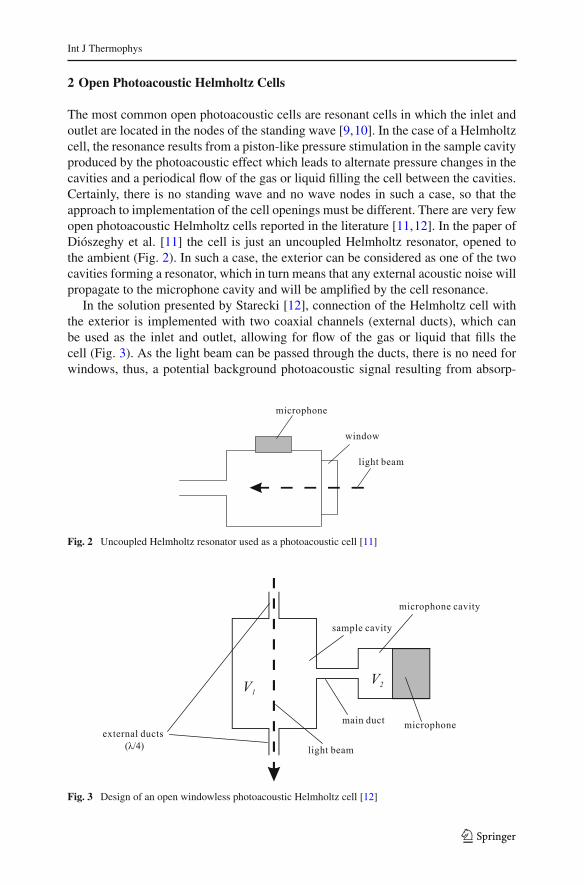
The most common open photoacoustic cells are resonant cells in which the inlet andoutlet are located in the nodes of the standing wave [9,10]. In the case of a Helmholtzcell, the resonance results from a piston-like pressure stimulation in the sample cavityproduced by the photoacoustic effect which leads to alternate pressure changes in thecavities and a periodical flow of the gas or liquid filling the cell between the cavities.Certainly, there is no standing wave and no wave nodes in such a case, so that theapproach to implementation of the cell openings must be different. There are very fewopen photoacoustic Helmholtz cells reported in the literature [11,12]. In the paper ofDiószeghy et al. [11] the cell is just an uncoupled Helmholtz resonator, opened tothe ambient (Fig. 2). In such a case, the exterior can be considered as one of the twocavities forming a resonator, which in turn means that any external acoustic noise willpropagate to the microphone cavity and will be amplified by the cell resonance.
In the solution presented by Starecki [12], connection of the Helmholtz cell withthe exterior is implemented with two coaxial channels (external ducts), which canbe used as the inlet and outlet, allowing for flow of the gas or liquid that fills thecell (Fig. 3). As the light beam can be passed through the ducts, there is no need forwindows, thus, a potential background photoacoustic signal resulting from absorp-
Fig. 2 Uncoupled Helmholtz resonator used as a photoacoustic cell [11]
Fig. 3 Design of an open windowless photoacoustic Helmholtz cell [12]
123

Int J Thermophys
tion of the light by the windows is eliminated. Dimensions of the ducts are cho-sen in such a way that their acoustic impedance observed from the sample cavityis high. As a result, pressure changes produced by the photoacoustic effect are onlyslightly suppressed by the presence of these ducts. High acoustic impedance of theducts can be obtained by setting their length to a quarter of the acoustic wave cor-responding to the frequency of the light beam modulation. A duct of such a lengthshould be treated as an acoustic transmission line, and the input impedance Z i ofa quarter-wave transmission line loaded on the other end with the impedance Zois
Z i = Z2ω
Zo(3)
where Zω is the characteristic impedance of the line. It can be easily noticed, that if Zo isthe acoustic impedance of the cell exterior (meaning that Zo is low), then the impedanceZ i of the duct observed from the sample cavity is high. As a result, frequency responsesof the closed cell from Fig. 1 designed for operation at the Helmholtz resonance andof the corresponding open cell from Fig. 3 in which the length of the external ductswas appropriately adjusted are nearly identical within the frequency range close to theresonance (Fig. 4) [13]. Unfortunately, as the sample cavity volume V1 is small, itsacoustic impedance is definitely not low. Thus, due to Eq. 3, acoustic impedances ofthe external ducts observed from the exterior are relatively low. This in turn means thatthe external acoustic noise will easily penetrate such a cell, which is clearly visible inFig. 4.
Fig. 4 Frequency responses of the cells shown in Figs. 1 and 3, and noise infiltration of the open Helmholtzcell from Fig. 3 [13]
123

Int J Thermophys
3 Improved Open Helmholtz Cell Design
Although the design presented in Fig. 3 has some advantages, it suffers from strongpropagation of the external noise inside the cell, which makes its applications imprac-tical. Attenuation of external noise can be substantially improved by means of acousticbuffers with quarter-wave ducts as shown in Fig. 5. If the buffers are of relatively highvolume, their acoustic impedance can be considered as low. Thus, according to Eq. 3,the impedance of the external ducts observed from the exterior will be high. Similarly,the impedance of the internal ducts observed from the sample cavity will be high.As a result, infiltration of the external acoustic noise should be significantly reduced(in comparison to the cell design from Fig. 3), while the frequency response of thecell around the Helmholtz resonance created by the sample cavity, microphone cavity,
Fig. 5 Improved windowless photoacoustic Helmholtz cell
123

Int J Thermophys
Fig. 6 Modified open photoacoustic Helmholtz cell
and the main duct should not change noticeably. If the internal and external ducts arecoaxial, the light beam can be passed through them, similarly as in the case of the cellin Fig. 3, so that there will be no background signal produced by the absorption oflight by the cell walls or windows. Unfortunately, due to the acoustic-wave-dependentdimensions, the optical path length in the cell increases with the frequency of lightbeam modulation fmod. For example, if fmod = 1 kHz, the corresponding acousticwavelength in the air is approx. 35 cm. In such a case the optical path length willbe probably around 50 cm (four quarter-wave ducts plus the length of the samplecavity and two acoustic buffers). Taking into consideration that the diameters of theducts should be rather small (typically not more than 3 mm), high precision would berequired from the manufacturing of such a cell, as well as from the light beam collima-tion and positioning. These requirements can be significantly lowered if the cell designis modified as in Fig. 6. In such a case high precision is needed on a twice shorter
123

Int J Thermophys
Fig. 7 Frequency responses of the open Helmholtz cells with structures shown in Figs. 3 and 6
distance (two quarter-wave ducts plus length of the sample cavity). The modified cellis equipped with windows, which will introduce a background photoacoustic signaldue to parasitic absorption of the light beam. However, assuming that the sample cav-ity has a volume of a few cm3, while the volume of the buffers will be a few hundredcm3, and taking into consideration the relationship given by Eq. 1, the backgroundsignal resulting from such an absorption will be approximately VB/V1 ≈ 100 timessmaller in comparison to the corresponding background signal in the cell with thestructure given in Fig. 1. An important advantage of the modified cell from Fig. 6 isthat as the external ducts are no longer in the optical path; therefore, their diameterscan be reduced. This should improve attenuation of the external acoustic noise, whichin the case of an open cell is more likely to limit sensitivity of the setup, rather thanthe background signal from the window absorption.
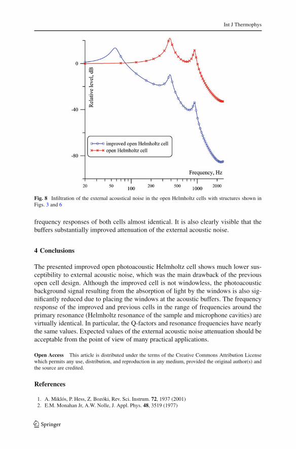
Preliminary evaluation of the improved open cell properties was based on computersimulations. Models used in these simulations had been previously tested and proved togive very good results in modeling of photoacoustic cells with a multicavity structure[14]. Comparison of frequency responses and noise properties of the original (Fig. 3)and improved (Fig. 6) photoacoustic open Helmholtz cells are given in Figs. 7 and8. In the evaluated improved cell, all the internal and external ducts had a length of50 mm, a diameter of 3 mm, and the buffer volumes were 100 cm3. In both cells thesample cavity volume was 2 cm3, the microphone cavity volume was 1.5 cm3, andthe main duct was 35 mm long and 3 mm in diameter. The frequency response of theimproved cell has an additional Helmholtz resonance at a frequency of about 50 Hz,resulting from interaction of the main part of the cell with the buffer volumes. Athigher frequencies the impedance of the buffer volumes is low enough to make the
123
Int J Thermophys
Fig. 8 Infiltration of the external acoustical noise in the open Helmholtz cells with structures shown inFigs. 3 and 6
frequency responses of both cells almost identical. It is also clearly visible that thebuffers substantially improved attenuation of the external acoustic noise.
4 Conclusions
The presented improved open photoacoustic Helmholtz cell shows much lower sus-ceptibility to external acoustic noise, which was the main drawback of the previousopen cell design. Although the improved cell is not windowless, the photoacousticbackground signal resulting from the absorption of light by the windows is also sig-nificantly reduced due to placing the windows at the acoustic buffers. The frequencyresponse of the improved and previous cells in the range of frequencies around theprimary resonance (Helmholtz resonance of the sample and microphone cavities) arevirtually identical. In particular, the Q-factors and resonance frequencies have nearlythe same values. Expected values of the external acoustic noise attenuation should beacceptable from the point of view of many practical applications.
Open Access This article is distributed under the terms of the Creative Commons Attribution Licensewhich permits any use, distribution, and reproduction in any medium, provided the original author(s) andthe source are credited.
References
1. A. Miklós, P. Hess, Z. Bozóki, Rev. Sci. Instrum. 72, 1937 (2001)2. E.M. Monahan Jr, A.W. Nolle, J. Appl. Phys. 48, 3519 (1977)
123

Int J Thermophys
3. D. Ducharme, A. Tessier, R.M. Leblanc, Rev. Sci. Instrum. 50, 1461 (1979)4. J. Pelzl, K. Klein, O. Nordhaus, Appl. Opt. 21, 94 (1982)5. N.C. Fernelius, Appl. Opt. 18, 1784 (1979)6. R. Kästle, M.W. Sigrist, Appl. Phys. B 63, 389 (1996)7. V. Zeninari, V.A. Kapitanov, D. Courtois, Yu.N. Ponomarev, Infrared Phys. Technol. 40, 1 (1999)8. M.B. Pushkarsky, M.E. Webber, C.K.N. Patel, Appl. Phys. B 77, 381 (2003)9. S. Schäfer, M. Mashni, J. Sneider, A. Miklós, P. Hess, H. Pitz, K.-U. Pleban, V. Ebert, Appl. Phys. B
66, 511 (1998)10. S. Schilt, J.-P. Besson, L. Thévenaz, Appl. Phys. B 82, 319 (2006)11. T. Diószeghy, A. Miklós, A. Keleman, A. Lórincz, J. Appl. Phys. 56, 2105 (1985)12. T. Starecki, Acta Phys. Pol. A 114, 211 (2008)13. T. Starecki, Acta Phys. Pol. A 114, 199 (2008)14. T. Starecki, J. Acoust. Soc. Am. 122, 2118 (2007)
123