An Overview of Various Waveform Contenders Based on OFDM for 5G Communication
arX
iv:1
601.
0479
5v1
[cs.
IT]
19 J
an 2
016
1
ImprovedN-continuous OFDM for 5G
Wireless CommunicationsPeng Wei, Lilin Dan, Yue Xiao, Wei Xiang, and Shaoqian Li
Abstract
N-continuous orthogonal frequency division multiplexing (NC-OFDM) is a promising technique to
obtain significant sidelobe suppression for baseband OFDM signals, in future 5G wireless communi-
cations. However, the precoder of NC-OFDM usually causes severe interference and high complexity.
To reduce the interference and complexity, this paper proposes an improved time-domainN-continuous
OFDM (TD-NC-OFDM) by shortening the smooth signal, which islinearly combined by rectangularly
pulsed OFDM basis signals truncated by a smooth window. Furthermore, we obtain an asymptotic
spectrum analysis of the TD-NC-OFDM signals by a closed-form expression, calculate its low complexity
in OFDM transceiver, and derive a closed-form expression ofthe received signal-to-interference-plus-
noise ratio (SINR). Simulation results show that the proposed low-interference TD-NC-OFDM can
achieve similar suppression performance but introduce negligible bit error rate (BER) degradation and
much lower computational complexity, compared to conventional NC-OFDM.
Index Terms
Orthogonal frequency division multiplexing (OFDM), sidelobe suppression,N-continuous OFDM
(NC-OFDM).
I. INTRODUCTION
Orthogonal frequency division multiplexing (OFDM) [1] hasbeen one of the most popular multicarrier
transmission techniques in future 5G wireless communications [2], [3] due to its high-speed data transmis-
sion and inherent robustness against the inter-symbol interference (ISI). However, in rectangularly pulsed
OFDM systems, the signal possesses a discontinuous pulse edge and thus exhibits large spectral sidelobes.
The authors are with the school of National Key Laboratory ofScience and Technology on Communications, University of Elec-
tronic Science and Technology of China, Chengdu, China (e-mail: [email protected];{lilindan, xiaoyue}@uestc.edu.cn).
Wei Xiang is with the school of Mechanical and Electrical Engineering Faculty of Health, Engineering and Sciences, University
of Southern Queensland, Austrialia (e-mail: [email protected]).
January 20, 2016 DRAFT

2
Thus, power leakage due to sidelobes, which is also known as out-of-band power emission, causes severe
interference to adjacent channels [6], especially in cognitive radio (CR) and carrier aggregation (CA)
combined 5G systems [4], [5].
For improving conventional OFDM in out-of-band emission, various methods have been proposed for
sidelobe suppression [7–18]. The windowing technique in [7] extends the guard interval in the price of
a reduction in spectral efficiency. Cancellation carriers [8], [9] consume extra power and incur a signal-
to-noise ratio (SNR) loss with high complexity. In the precoding methods [10–12], complicate decoding
algorithms are required to eliminate the interference caused by the precoders.
NC-OFDM techniques [13–19] smooth the amplitudes and phases of the OFDM signal by making
the OFDM signal and its firstN derivatives continuous (so-calledN-continuous). Conventional NC-
OFDM [13] obtains theN-continuous signal at the expense of high interference. Aiming at optimizing
the frequency domain precoder in [13], Beek et al. proposed the memoryless scheme in [14] and the
improved scheme [15] nulling the spectrum at several chosenfrequencies. On the other hand, to enable
low-complexity signal recovery in NC-OFDM, several approaches have been proposed [16–18]. However,
similar to the precoding techniques, the existing NC-OFDM techniques need robust signal recovery
algorithms for reception. Among them, some methods degradesystem performance, such as peak-to-
average-power ratio (PAPR) growth in [14] and high complexity of transmitter in [16], [17].
In this paper, to reduce the interference of the NC-OFDM signals and obtain a low-complexity
transceiver, we propose a low-interference time-domainN-continuous OFDM (TD-NC-OFDM) based
on the conventional TD-NC-OFDM [19]. A smooth signal is superposed in the front part of each OFDM
symbol to achieveN-continuous OFDM signal, including smoothing both edges ofthe transmitted signal.
The smooth signal is linearly combined by the basis vectors in a basis set, which is composed of
the rectangularly pulsed OFDM basis signals truncated by a smooth window function for an example.
Furthermore, we give rise to analyses of spectrum, complexity and signal-to-interference-plus-noise ratio
(SINR) in the low-interference TD-NC-OFDM. Among them, an asymptotic expression of PSD of the TD-
NC-OFDM signal is first obtained, where the sidelobes asymptotically decay withf−N−2, when the firstN
derivatives of the OFDM signal are all continuous. Then, we compare the complexity among NC-OFDM,
TD-NC-OFDM and its low-interference scheme, to show the complexity reduction of the proposed low-
interference scheme. The closed-form expression of the received SINR of the low-interference scheme is
also calculated to show the slight SNR loss. Simulation results show that the low-interference scheme can
achieve as notable sidelobe suppression as NC-OFDM method [13] with excellent bit error rate (BER)
performance and low complexity.
The remainder of the paper is organized as follows. In Section 2, the OFDM signaling is briefly
January 20, 2016 DRAFT
3
introduced, the traditional NC-OFDM is reviewed. Section 3proposes the low-interference TD-NC-OFDM
model, gives the linear combination design of the smooth signal with a new basis set, and describes the
transmitter. In Section 4, the effect of the low-interference TD-NC-OFDM on sidelobe decaying and the
received SINR is analyzed as well as the computational complexity of the transceiver. Finally, Section 5
draws concluding remarks.
Notation: Boldfaced lowercase and uppercase letters represent column vectors and matrices, respec-
tively. {A}m,n indicates the element in themth row andnth column of matrixA. TheM ×M identity
matrix andM ×N zero matrix are denoted byIM and0M×N , respectively.| · | represents the absolute
value. The trace and expectation of a matrix are representedby Tr{·} and E{·}, respectively.AT ,
A∗, AH andA−1 denote the transposition, conjugate, conjugate transposition, and inverse of matrixA,
respectively.
II. SYSTEM ASPECTS ANDN-CONTINUOUS OFDM
A. OFDM signaling
In a baseband OFDM system, the input bit stream of theith OFDM symbol is first modulated onto an
uncorrelated complex-valued data vectorxi = [xi,k0, xi,k1
, . . . , xi,kK−1]T drawn from a constellation, such
as phase-shift keying (PSK) or quadrature amplitude modulation (QAM). The complex-valued data vector
is mapped ontoK subcarriers with the index setK = {k0, k1, . . . , kK−1}. An OFDM signal is formed by
summing all theK-modulated orthogonal subcarriers with equal frequency spacing∆f = 1/Ts, whereTs
is the OFDM symbol duration. Theith OFDM time-domain symbol, assuming a normalized rectangular
time-domain windowR(t) [10], can be expressed as
yi(t) =
K−1∑
r=0
xi,krej2πkr∆ft,−Tcp ≤ t < Ts (1)
whereTcp is the cyclic prefix (CP) duration. Then, in the time range of(−∞,+∞), the transmitted
OFDM signals(t) can be written as
s(t) =
+∞∑
i=−∞
yi (t− iT ). (2)
whereT = Ts + Tcp.
After the OFDM signal is oversampled by a time-domain sampling interval Tsamp = Ts/M , the
discrete-time OFDM signal is expressed as
yi(m) =1
M
K−1∑
r=0
xi,krej2π
kr
Mm, (3)
wherem ∈ M = {−Mcp, . . . , 0, . . . ,M − 1}, andMcp is the length of CP samples.
January 20, 2016 DRAFT

4
B. N-continuous OFDM
To improve the continuity of the time-domain OFDM signal, the conventional NC-OFDM [13] intro-
duces a frequency-domain precoder to making the OFDM signaland its firstN derivatives continuous.
NC-OFDM follows that
yi(t) =
K−1∑
r=0
xi,krej2πkr∆ft,−Tcp ≤ t < Ts (4)
y(n)i (t)
∣
∣
∣
t=−Tcp
= y(n)i−1(t)
∣
∣
∣
t=Ts
, (5)
wherexi,kris the precoded symbol on therth subcarrier, andy(n)i (t) is thenth-order derivative ofyi(t)
with n ∈ UN = {0, 1, . . . , N}.
Based on (4) and (5), the precoding process can be summarizedas
xi = x0, i = 0
xi = (IK −P)xi +PΦH xi−1, i > 0
(6)
whereIK is the identity matrix,P = ΦHAH(AAH)−1AΦ, {A}n+1,r+1 = knr , Φ = diag(ejϕk0 , ejϕk1 , . . . , ejϕkK−1),
andϕ = −2πβ with β = Tcp/Ts. Figure 1 depicts the spectrally precoded NC-OFDM transmitter. Theith
frequency-domain data vectorxi is first precoded. The precoded data vectorxi =[
xi,k0, xi,k1
, . . . , xi,kK−1
]T
then undergoes the inverse fast Fourier transform (IFFT), and finally the CP is added to generate the
transmission signal.
Precoder
Delay i
ix ix
1i-x
N-NN continuous OFDMN-continuous OFDM
AddCP
Subcarrier
mapping
IFFT
Fig. 1. Block diagram of theN-continuous OFDM transmitter.
III. PROPOSEDLOW-INTERFERENCESCHEME OFTD-NC-OFDM
Conventional TD-NC-OFDM [19] and Conventional NC-OFDM [13] cause high interference, which
is needed to be reduced by complicate signal recovery algorithms [13, 16, 18]. As show in Figure 2
(a), the interference term, defined as the smooth signalwi(m), is located in the whole time-domain in
the conventional TD-NC-OFDM as well as NC-OFDM . To eliminate the interference and simplify the
January 20, 2016 DRAFT

5
time
(a)
( )s m
( )w m
( )s m
( )w mw m 0 0
1( )iy m-
( )iy m
CP CP
CP CP
CPCP
Adjacent point atM
1( )iw m-
( )iw m
1( )iw m-1iw m1( )( )i- ( )iw miw m( )( )i
cpM- 0 1M -
(b)
( )s m
Fig. 2. Conventional and proposed ways of of adding the smooth signal in the time domain: (a) Addition in the whole OFDM
symbol; (b) Addition in the front of each OFDM symbol.
receiver, we truncatewi(m) with a window function. As illustrated in in Figure 2 (b), thetruncated term
wi(m) only locates in the front section of each OFDM symbol.
To make the OFDM signalN-continuous,wi(m) should satisfy
yi(m) = yi(m) + wi(m), (7)
w(n)i (m)
∣
∣
∣
m=−Mcp
= y(n)i−1(m)
∣
∣
∣
m=M− y
(n)i (m)
∣
∣
∣
m=−Mcp
. (8)
wi(m) is the linear combination of the firstN+1 basis vectors in a basis setQ, written as
wi(m) =
N∑
n=0bi,nfn(m), m ∈ L
0, m ∈ M−L
, (9)
whereL = {−Mcp,−Mcp + 1, . . . ,−Mcp + L− 1} indicates the location ofwi(m) with the length of
L, and the basis setQ is given by
Q =
{
qn
∣
∣
∣qn =[
fn(−Mcp), fn(−Mcp + 1), . . . , fn(−Mcp + L− 1)]T
, n ∈ U2N
}
, (10)
whereU2N = {0, 1, . . . , 2N}. In (9), the design of the basis signalfn(m) and the calculation of the
coefficientsbi,n ∈ bi = [bi,0, bi,1, . . . , bi,N ]T will be specified as follows.
January 20, 2016 DRAFT

6
To guarantee the smoothness ofwi(m) and to obtain theN-continuous signal, an example of designing
fn(m) is given by
fn(m) = f (n)(m)gh(m), (11)
for m ∈ L, and fn(m) = 0 for m ∈ M−L. In L,
f (n)(m) = 1/M (j2π/M)n∑
kr∈K
knr ejϕkrej2π
kr
Mm, (12)
andgh(m) is the right half part of a baseband-equivalent window function g(m). Thus, the discontinuity
at the adjacent point between two consecutive OFDM symbols can be eliminated bywi(m) from only a
single side of the adjacent point. Under the constraint ofgh(m), the interference caused bywi(m) can be
limited to the front section of the OFDM symbol. In order to satisfy (9), g(m) should be considered as a
smooth and zero-edged window function, such as a triangular, Hanning, or Blackman window function.
On the other hand, the linear combination coefficientsbi,n in (9) can be calculated as
bi = P−1
f
yi−1(M)− yi(−Mcp)
P1xi−1 −P2xi
, (13)
where Pf is a (N + 1) × (N + 1) symmetric matrix related toQ with element{
Pf
}
n+1,v+1is
f (n+v)(−Mcp), and element{P1}n,r+1 = 1/M (j2πkr/M)n and element{P2}n,r+1 = 1/M (j2πkr/M)n ejϕkr
for n 6= 0.
Figure 3 shows the block diagram of the proposed low-interference TD-NC-OFDM. According toK and
Q, the matricesQf = [q0,q1, . . . ,qN ], P−1f
, P1, andP2, can be calculated and stored in advance. Then,
the data is first mapped and transformed to the time domain by the IFFT. Furthermore, the oversampled
OFDM signal is appended by a CP. Finally, under the initialization of y−1 = 0, the smooth signal is
added onto the OFDM signal constructed byMs OFDM symbolsyi to generate the following transmit
signal
yi =
yi +Qfbi, 0 ≤ i ≤ Ms
Qfbi, i = Ms + 1. (14)
IV. A NALYSIS OF SPECTRUM AND COMPLEXITY
A. Spectral Analysis
According to the definition of PSD [12] and the relationship between spectral roll-off and continuity
[20], the PSD of the OFDM signal processed by the low-interference scheme is achieved as follows.
All the derivatives of the OFDM signals(t) are known to exist except for around the two edges and on
the points between adjacent OFDM symbols. Meanwhile, except for these non-differentiable points, the
January 20, 2016 DRAFT

7
ix iy
Subcarrier
mapping
J
IFFT
Generate
smooth signal
ib
iw
fPf f
Qf
Calculate
coordinate
AddCP
iy
New basis set
Fig. 3. Block diagram of the OFDM transmitter with the proposed low-interference TD-NC-OFDM.
smooth signal also possesses derivatives of all orders, according to the existence of all the derivatives of
the basis functionfn(m). Then, we assume that at non-differentiable points, the first N-1 derivatives of
the smoothed OFDM signals(t) are continuous, and theNth-order derivatives(N)(t) has finite amplitude
discontinuity. We also suppose that all the derivatives ofs(t) approach zeroes , which corresponds to
(14). Firstly, based on [20], we can obtain
F {s(t)} =1
(j2πf)N−1
+∞∫
−∞
s(N−1)(t)e−j2πftdt. (15)
Furthermore, sinces(N)(t) has finite amplitude discontinuities, by settingu = s(N−1)(t) and dv =
e−j2πftdt in the above expression, we arrive at
F {s(t)} =1
(j2πf)N−1
s(N−1)(t)e−j2πft
−j2πf
∣
∣
∣
∣
t=+∞
t=−∞
−
+∞∫
−∞
s(N)(t)e−j2πft
−j2πfdt
=1
(j2πf)N
+∞∫
−∞
s(N)(t)e−j2πftdt. (16)
Becauses(N)(t) has finite amplitude discontinuities at the adjacent points, from (2), s(N)(t) can be
written as
s(N)(t) =
+∞∑
i=−∞
y(N)i (t− iT ). (17)
It is inferred in (17) that theNth derivativey(N)i (t) can be assumed being windowed by the rectangular
functionR(t). Therefore, based on the definition of PSD, (16), and (17), the PSD ofs(t) can be expressed
January 20, 2016 DRAFT

8
as
Ψ(f)= limU→∞
1
2UTE
∣
∣
∣
∣
∣
F
{
U−1∑
i=−U
y(N)i (t− iT )
(j2πf)N
}∣
∣
∣
∣
∣
2
= limU→∞
1
2UTE
∣
∣
∣
∣
∣
∣
U−1∑
i=−U
F{
y(N)i (t)
}
(j2πf)Ne−j2πfiT
∣
∣
∣
∣
∣
∣
2
.
(18)
Eq. (18) indicates that the spectrum of the TD-NC-OFDM signal is related to the expectation ofy(N)i (t)
and f−N . In this paper, the conventional Blackman window function is used as an example, given as
g(t) = 0.42− 0.5 cos (2πρt) + 0.08 cos (4πρt) whereρ = 1/ ((2L− 2)Tsamp). By substituting (9), (11),
(12), and (14) into (18), the PSD of the smoothed OFDM signal in low-interference scheme is expressed
by
Ψ(f) = limi→∞
1
2UTE
∣
∣
∣
∣
∣
∣
U−1∑
i=−U
e−j2πfiT (j2πf)−N∑
kr∈K
(
j2πkrTs
)N
xi,krsinc (fr(1 + β)) ejπfr(1−β)
+1
T
N∑
n=0
bi,n
N∑
n=0
N
n
∑
kr∈K
(
j2πkrTs
)N−n+n−Tcp+Tp∫
−Tcp
g(n)h (t)ej2πfrt/Tsdt
∣
∣
∣
∣
∣
∣
2
= limi→∞
1
2UTE
∣
∣
∣
∣
∣
∣
U−1∑
i=−U
e−j2πfiT (fTs)−N ×
∑
kr∈K
kNr xi,krsinc (fr(1 + β)) ejπfr(1−β)
+1
T
N∑
n=0
bi,n
N∑
n=0
N
n
(
j2π
Ts
)n−n∑
kr∈K
kN−n+nr Gn(f)
∣
∣
∣
∣
∣
∣
2
(19)
whereGn(f) is given by
Gn(f) = ejfr
0.42(n)Tpsinc (µfr)−
0.5(2πρ)n cos (πµfr)
1− (ρTs/fr)2
(
cos (πn/2)
jπfr/Ts− πρ
sin (πn/2)
(πfr/Ts)2
)
+0.08(4πρ)n sin (πµfr)
1− (2ρTs/fr)2
(
cos (πn/2)
πfr/Ts− j2πρ
sin (πn/2)
(πfr/Ts)2
)
,
where sinc(x) , sin(πx)/(πx), and fr = πfr(Tp − 2Tcp)/Ts with fr = kr − Tsf , Tp = (L− 1)Tsamp,
andµ = Tp/Ts.
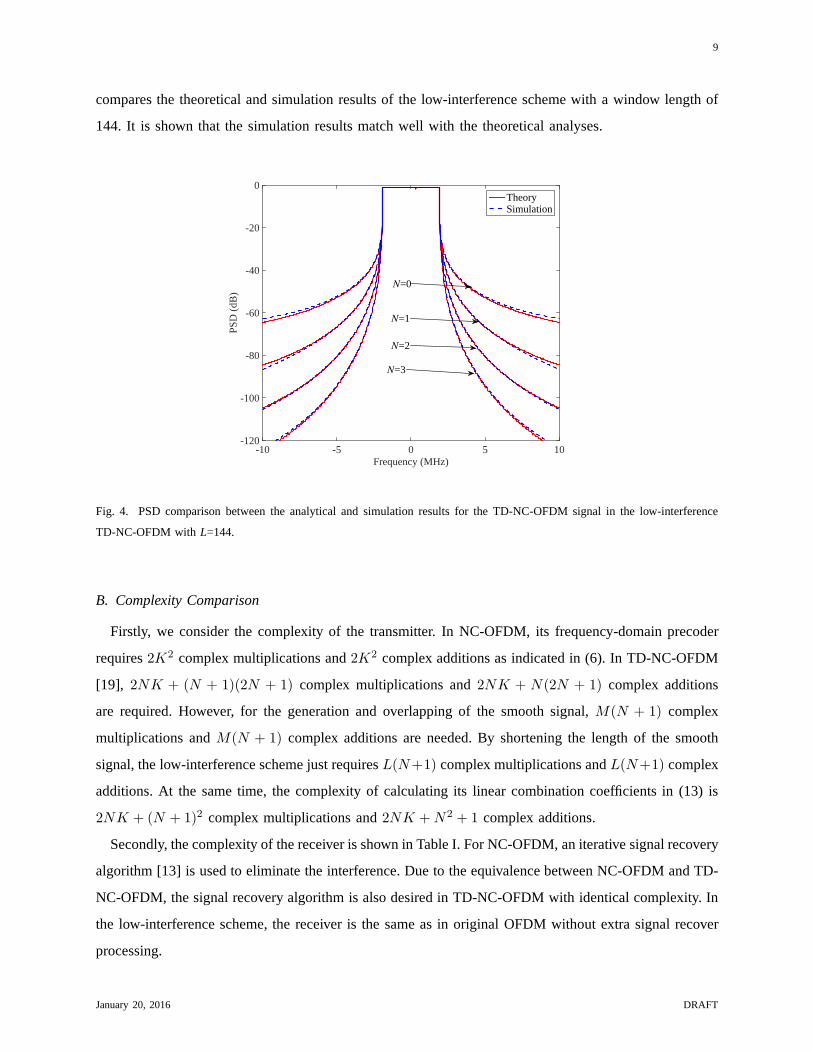
Eq. (19) shows that the power spectral roll-off of the smoothed signal, whose firstN-1 derivatives are
continuous, decays withf−2N−2. Moreover,Gn(f) reveals that the sidelobe is affected by the length
of g(t), so that a rapid sidelobe decaying can be achieved by increasing the length ofg(t). Figure 4
January 20, 2016 DRAFT
9
compares the theoretical and simulation results of the low-interference scheme with a window length of
144. It is shown that the simulation results match well with the theoretical analyses.
Frequency (MHz)-10 -5 0 5 10
PS
D (
dB)
-120
-100
-80
-60
-40
-20
0TheorySimulation
N=0
N=1
N=2
N=3
Fig. 4. PSD comparison between the analytical and simulation results for the TD-NC-OFDM signal in the low-interference
TD-NC-OFDM with L=144.
B. Complexity Comparison
Firstly, we consider the complexity of the transmitter. In NC-OFDM, its frequency-domain precoder
requires2K2 complex multiplications and2K2 complex additions as indicated in (6). In TD-NC-OFDM
[19], 2NK + (N + 1)(2N + 1) complex multiplications and2NK + N(2N + 1) complex additions
are required. However, for the generation and overlapping of the smooth signal,M(N + 1) complex
multiplications andM(N + 1) complex additions are needed. By shortening the length of the smooth
signal, the low-interference scheme just requiresL(N+1) complex multiplications andL(N+1) complex
additions. At the same time, the complexity of calculating its linear combination coefficients in (13) is
2NK + (N + 1)2 complex multiplications and2NK +N2 + 1 complex additions.
Secondly, the complexity of the receiver is shown in Table I.For NC-OFDM, an iterative signal recovery
algorithm [13] is used to eliminate the interference. Due tothe equivalence between NC-OFDM and TD-
NC-OFDM, the signal recovery algorithm is also desired in TD-NC-OFDM with identical complexity. In
the low-interference scheme, the receiver is the same as in original OFDM without extra signal recover
processing.
January 20, 2016 DRAFT

10
Assume that a complex addition is equivalent to two real additions; a complex multiplication to four real
multiplications plus two real additions; and a real-complex multiplication to two real multiplications. The
complexity comparison among NC-OFDM, TD-NC-OFDM and the low-interference scheme is shown in
Table I, whereLR denotes the number of iterations in the signal recovery algorithm [13].
TABLE I
COMPLEXITY COMPARISON AMONGNC-OFDM, TD-NC-OFDMAND ITS LOW-INTERFERENCESCHEME
Scheme Real multiplication Real addition
NC-OFDM Transmitter O(8K2) O(8K2)
Receiver O(16(N + 1)KLR) O(16(N + 1)KLR)
TD-NC-OFDM Transmitter O(8NK + 4(N + 1)M) O(8NK + 4(N + 1)M)
Receiver O(16(N + 1)KLR) O(16(N + 1)KLR)
Low-interference scheme Transmitter O(8NK + 4(N + 1)L) O(8NK + 4(N + 1)L)
Receiver 0 0
M-point IFFT/FFT O(2M log2M) O(2M log
2M)
The low-interference scheme considerably suppresses the sidelobes shown in Figure 4. Simultaneously,
since the length of the smooth signalL is often as short as the CP length or shorter in real systems, the
low-interference scheme is of lower transmitter complexity than NC-OFDM and the conventional TD-NC-
OFDM. Moreover, its complexity is comparable toM-point IFFT. On the other hand, the low-interference
scheme just requires the receiver of original OFDM, and avoiding extra processing in NC-OFDM and
TD-NC-OFDM receivers.
C. SINR Analysis
One disadvantage of NC-OFDM is that the transmit signal is easily interfered by the smooth signal.
Thus, a measure is needed to evaluate the interference in terms of the SNR loss. In this section, we
investigate the SINR of NC-OFDM, and demonstrate the effectiveness of the proposed low-interference
scheme in reducing the SNR loss, based on the analysis of the average power of the smooth signal.
In a multipath channel with time-domain coefficientshl in the lth path, theith received time-domain
OFDM symbolri(t) is given by
ri(t) =
L∑
l=1
hlyi(t− τl) + ni(t) (20)
whereτl is the time delay in thelth path, andni(t) is the AWGN noise with mean zero and variance
σ2n.
January 20, 2016 DRAFT
11
Becausexi is uncorrelated, i.e.,E{
xixHi
}
= IK andE{
xi−1xHi
}
= 0K×K, we can obtainE{
xHi xi
}
=
Tr{
E{
xixHi
}}
= K. Thus, the average power of the OFDM symbol vectoryi is
E{
yHi yi
}
=1
M2E{
xHi FfF
Hf xi
}
= E{
xHi xi
}
= K/M. (21)
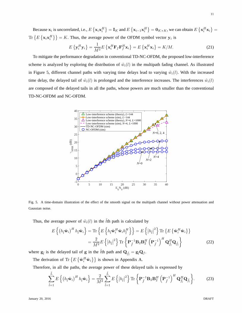
To mitigate the performance degradation in conventional TD-NC-OFDM, the proposed low-interference
scheme is analyzed by exploring the distribution ofwi(l) in the multipath fading channel. As illustrated
in Figure 5, different channel paths with varying time delays lead to varyingwi(l). With the increased
time delay, the delayed tail ofwi(l) is prolonged and the interference increases. The interferenceswi(l)
are composed of the delayed tails in all the paths, whose powers are much smaller than the conventional
TD-NC-OFDM and NC-OFDM.
EbN
0 (dB)
0 5 10 15 20 25 30 35 40
γS
INR (
dB)
-5
0
5
10
15
20
25
30
35
40Low-interference scheme (theory), L=144Low-interference scheme (sim), L=144Low-interference scheme (theory), N=4, L=1000Low-interference scheme (sim), N=4, L=1000TD-NC-OFDM (sim)NC-OFDM (sim)
N=0, 2, 4
N=4
N=0N=2
Fig. 5. A time-domain illustration of the effect of the smooth signal on the multipath channel without power attenuationand
Gaussian noise.
Thus, the average power ofwi(l) in the lth path is calculated by
E{
(
hlwi
)Hhlwi
}
= Tr{
E{
hlwHi wih
Hl
}}
= E{
∣
∣hl∣
∣
2}
Tr{
E{
wHi wi
}}
=2
M2E{
∣
∣hl∣
∣
2}
Tr
{
P−1f
B2BH2
(
P−1f
)HQH
flQfl
}
(22)
wheregl is the delayed tail ofg in the lth path andQfl= glQf .
The derivation ofTr{
E{
wHi wi
}}
is shown in Appendix A.
Therefore, in all the paths, the average power of these delayed tails is expressed byL∑
l=1
E{
(
hlwi
)Hhlwi
}
=2
M2
L∑
l=1
E{
∣
∣hl∣
∣
2}
Tr
{
P−1
fB2B
H2
(
P−1
f
)HQH
flQfl
}
. (23)
January 20, 2016 DRAFT

12
Finally, from (21)-(23), the received SINRγSINR is obtained by
γSINR =
L∑
l=1
E{
∣
∣hl∣
∣
2}
E{
yHi yi
}
σ2n +
L∑
l=1
E{
(
hlwi
)Hhlwi
}
=K/M
σ2n
L∑
l=1
E{
∣
∣hl∣
∣
2}
+
2L∑
l=1
E{
∣
∣hl∣
∣
2}
Tr
{
P−1
fB2B
H2
(
P−1
f
)HQH
flQfl
}
M2L∑
l=1
E{
∣
∣hl∣
∣
2}
. (24)
EbN
0 (dB)
0 5 10 15 20 25 30 35 40
γS
INR (
dB)
-5
0
5
10
15
20
25
30
35
40Low-interference scheme (theory), L=144Low-interference scheme (sim), L=144Low-interference scheme (theory), N=4, L=1000Low-interference scheme (sim), N=4, L=1000TD-NC-OFDM (sim)NC-OFDM (sim)
N=0N=2
N=4
N=0, 2, 4
Fig. 6. SINR analysis and simulations of the TD-NC-OFDM signals in the EVA fading channel, where the signal is modulated
by 16-QAM.
Figure 6 compares theoretical analysis in (24) and the simulation results in terms of the SINR. The
simulated Rayleigh channel employs the Extended VehicularA (EVA) channel model [21], whose excess
tap delay is [0, 30, 150, 310, 370, 710, 1090, 1730, 2510] ns with relative power [0, -1.5, -1.4, -3.6, -0.6,
-9.1, -7, -12, -16.9] dB. It is shown that the theoretical analysis aligns well with the simulations. It also
reveals that the SNR loss is negligible for the low-interference scheme. Moreover, the low-interference
scheme has much better SINR than NC-OFDM and TD-NC-OFDM. In general, even if the length of
wi(l) is increased, there is no extra need for signal recovery, which reduces the heavy computation load
in original NC-OFDM.
January 20, 2016 DRAFT
13
V. NUMERICAL RESULTS
This section presents simulation results to evaluate the PSD, complexity, and BER performance of
NC-OFDM, TD-NC-OFDM and proposed low-interference schemes. Simulations are performed in a
baseband-equivalent OFDM system with 256 subcarriers mapped onto the subcarrier index set{−128,−127, . . . , 127}.
16-QAM digital modulation is employed with a symbol periodTs = 1/15ms, time-domain oversampling
intervalTsamp = Ts/2048 and CP durationTcp = 144Tsamp. The PSD is evaluated by Welch’s averaged
periodogram method with a 2048-sample Hanning window and 512-sample overlap after observing 105
symbols. To investigate the BER performance, the signal is transmitted through the Extended Vehicular
A (EVA) channel model.
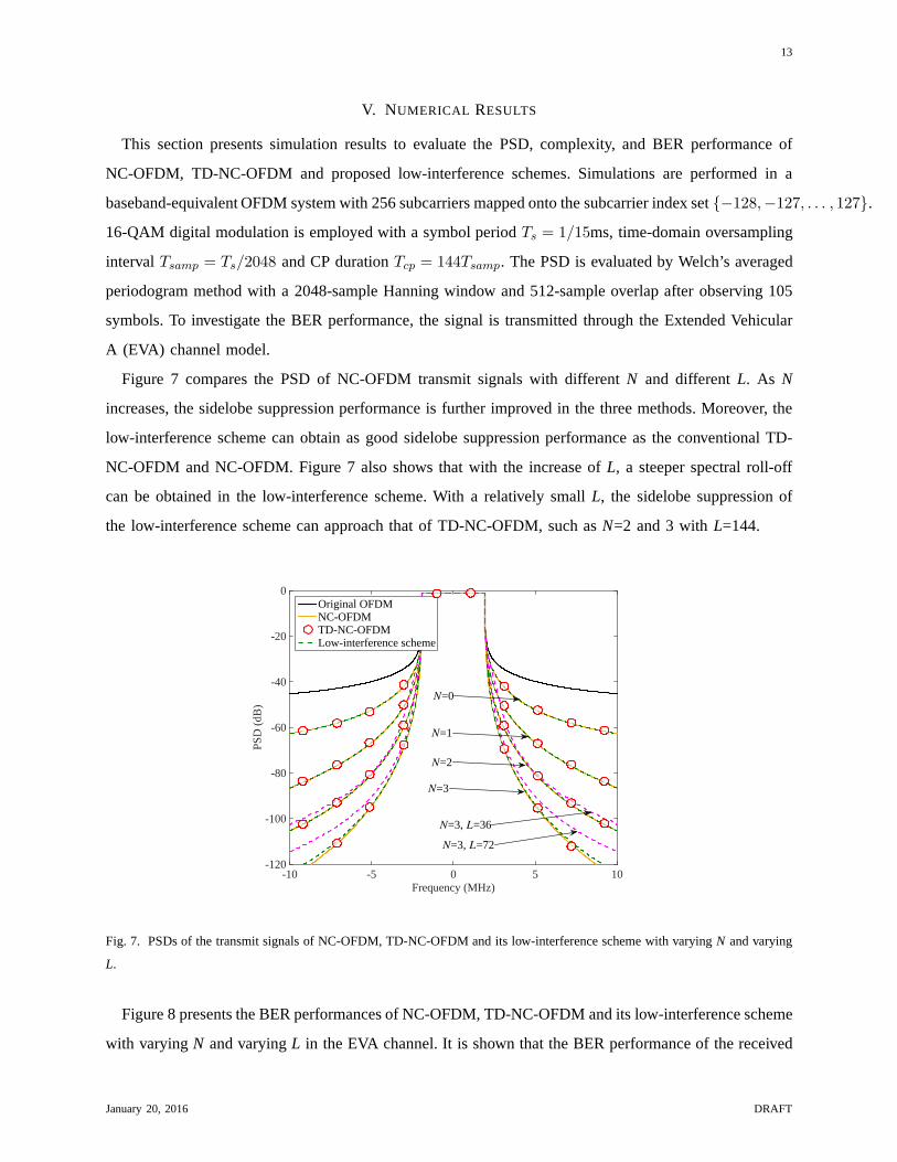
Figure 7 compares the PSD of NC-OFDM transmit signals with different N and differentL. As N
increases, the sidelobe suppression performance is further improved in the three methods. Moreover, the
low-interference scheme can obtain as good sidelobe suppression performance as the conventional TD-
NC-OFDM and NC-OFDM. Figure 7 also shows that with the increase of L, a steeper spectral roll-off
can be obtained in the low-interference scheme. With a relatively small L, the sidelobe suppression of
the low-interference scheme can approach that of TD-NC-OFDM, such asN=2 and 3 withL=144.
Frequency (MHz)-10 -5 0 5 10
PS
D (
dB)
-120
-100
-80
-60
-40
-20
0Original OFDMNC-OFDMTD-NC-OFDMLow-interference scheme
N=1
N=0
N=2
N=3
N=3, L=36
N=3, L=72
Fig. 7. PSDs of the transmit signals of NC-OFDM, TD-NC-OFDM and its low-interference scheme with varyingN and varying
L.
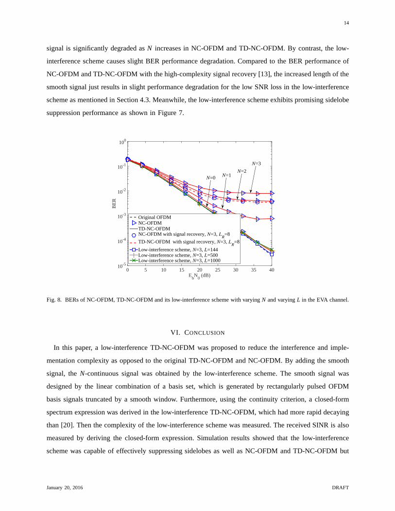
Figure 8 presents the BER performances of NC-OFDM, TD-NC-OFDM and its low-interference scheme
with varyingN and varyingL in the EVA channel. It is shown that the BER performance of thereceived
January 20, 2016 DRAFT
14
signal is significantly degraded asN increases in NC-OFDM and TD-NC-OFDM. By contrast, the low-
interference scheme causes slight BER performance degradation. Compared to the BER performance of
NC-OFDM and TD-NC-OFDM with the high-complexity signal recovery [13], the increased length of the
smooth signal just results in slight performance degradation for the low SNR loss in the low-interference
scheme as mentioned in Section 4.3. Meanwhile, the low-interference scheme exhibits promising sidelobe
suppression performance as shown in Figure 7.
EbN
0 (dB)
0 5 10 15 20 25 30 35 40
BE
R
10-5
10-4
10-3
10-2
10-1
100
Original OFDMNC-OFDMTD-NC-OFDMNC-OFDM with signal recovery, N=3, L
R=8
TD-NC-OFDM with signal recovery, N=3, LR=8
Low-interference scheme, N=3, L=144Low-interference scheme, N=3, L=500Low-interference scheme, N=3, L=1000
N=3
N=2N=1
N=0
Fig. 8. BERs of NC-OFDM, TD-NC-OFDM and its low-interference scheme with varyingN and varyingL in the EVA channel.
VI. CONCLUSION
In this paper, a low-interference TD-NC-OFDM was proposed to reduce the interference and imple-
mentation complexity as opposed to the original TD-NC-OFDMand NC-OFDM. By adding the smooth
signal, theN-continuous signal was obtained by the low-interference scheme. The smooth signal was
designed by the linear combination of a basis set, which is generated by rectangularly pulsed OFDM
basis signals truncated by a smooth window. Furthermore, using the continuity criterion, a closed-form
spectrum expression was derived in the low-interference TD-NC-OFDM, which had more rapid decaying
than [20]. Then the complexity of the low-interference scheme was measured. The received SINR is also
measured by deriving the closed-form expression. Simulation results showed that the low-interference
scheme was capable of effectively suppressing sidelobes aswell as NC-OFDM and TD-NC-OFDM but
January 20, 2016 DRAFT

15
with much better BER performance and much lower complexity.In this sense, the low-interference TD-
NC-OFDM is a promising alternative to conventional NC-OFDMin future cognitive radio and carrier
aggregation combined 5G systems.
ACKNOWLEDGMENT
This work was supported by the open research fund of NationalMobile Communications Research
Laboratory, Southeast University (No. 2013D05).
APPENDIX: DERIVATION OF Tr{
E{
wHi wi
}}
For ease of exposition, Eq. (13) is rewritten as
bi = P−1f
(P1xi−1 −P2xi) (25)
whereP1 andP2 include a row ofn = 0.
According to the construction ofP1 andP2, Tr{
E{
wHi wi
}}
can be expressed as
Tr{
E{
wHi wi
}}
= Tr{
E{
QfbibHi QH
f
}}
= Tr
{
E
{
QfP−1
fP1xi−1x
Hi−1P
H1
(
P−1
f
)HQH
f
}}
+Tr
{
E
{
QfP−1
fP2xix
Hi PH
2
(
P−1
f
)HQH
f
}}
= Tr
{
P−1
fP1P
H1
(
P−1
f
)HQH
fQf
}
+Tr
{
P−1
fP2P
H2
(
P−1
f
)HQH
fQf
}
.(26)
Then, we rewriteP1 andP2 asP1 = 1/MB2 andP2 = 1/MB2Φ with {B2}n+1,r+1 = (j2πkr/M)n.
We obtain
B1 = ΦHBT2 , (27)
with {B1}r+1,n+1 = (j2πkr/M)n e−jϕkr .
According to (27), we arrive at
Tr{
E{
wHi wi
}}
=1
M2Tr
{
P−1
fB2B
H2
(
P−1
f
)HQH
fQf
}
+1
M2Tr
{
P−1
fB2ΦΦHBH
2
(
P−1
f
)HQH
fQf
}
=2
M2Tr
{
P−1
fB2B
H2
(
P−1
f
)HQH
fQf
}
. (28)
January 20, 2016 DRAFT

16
REFERENCES
[1] Hwang T, Yang C, Wu G, et al. OFDM and its wireless applications: A survey. IEEE Trans Veh Technol, 2009, 58:
1673-1694
[2] Wang C X, Haider F, Gao X, et al. Cellular architecture andkey technologies for 5G wireless communication networks.
IEEE Commun Mag, 2014, 52: 122-130
[3] Wang Y, Li J, Huang L, et al. 5G mobile: spectrum broadening to higher-frequency bands to support high data rates. IEEE
Trans Veh Technol, 2014, 9: 39-46
[4] Hong X, Wang J, Wang C X, et al. Cognitive radio in 5G: a perspective on energy-spectral efficiency trade-off. IEEE
Commun Mag, 2014, 52: 46-53
[5] Yuan G, Zhang X, Wang W, et al. Carrier aggregation for LTE-advanced mobile communication systems. IEEE Commun
Mag, 2010, 48: 88-93
[6] Bogucka H, Wyglinski A M, Pagadarai S, et al. Spectrally agile multicarrier waveforms for opportunistic wireless access.
IEEE Commun Mag, 2011, 49: 108-115
[7] Weiss T, Hillenbrand J, Krohn A, et al. Mutual interference in OFDM-based spectrum pooling systems. In: The 59th IEEE
Vehicular Technology Conference Spring (VTC 2004-Spring), Milan, 2004. 1873-1877
[8] Brandes S, Cosovic I, Schnell M. Reduction of out-of-band radiation in OFDM systems by insertion of cancellation carriers.
IEEE Commun Lett, 2006, 10: 420-422
[9] Qu D, Wang Z, Jiang T. Extended active interference cancellation for sidelobe suppression in cognitive radio OFDM
systems with cyclic prefix. IEEE Trans Veh Technol, 2010, 59:1689-1695
[10] Ma M, Huang X, Jiao B, et al. Optimal orthogonal precoding for power leakage suppression in DFT-based systems. IEEE
Trans Commun, 2011, 59: 844-853
[11] Zhang J, Huang X, Cantoni A, et al. Sidelobe suppressionwith orthogonal projection for multicarrier systems. IEEETrans
Commun, 2012, 60: 589-599
[12] Chung C D. Spectrally precoded OFDM. IEEE Trans Commun,2006, 54: 2173-2185
[13] Beek de van J, Berggren F.N-continuous OFDM. IEEE Commun Lett, 2009, 13: 1-3
[14] Beek de van J, Berggren F. EVM-constrained OFDM precoding for reduction of out-of-band emission. In: The 70th
Vehicular Technology Conference Fall (VTC 2009-Fall), Anchorage, 2009. 1-5
[15] Beek de van J. Sculpting the multicarrier spectrum: a novel projection precoder. IEEE Commun Lett. 2009, 13: 881-883
[16] Ohta M, Iwase A, Yamashita K. Improvement of the error characteristics of anN-continuous OFDM system with low data
channels by SLM. In: The 2011 IEEE International Conferenceon Communications (ICC 2011), Kyoto, 2011. 1-5
[17] Ohta M, Okuno M, Yamashita K. Receiver iteration reduction of anN-continuous OFDM system with cancellation tones.
In: The 2011 IEEE Global Telecommunications Conference (GLOBECOM 2011), Kathmandu, 2011. 1-5
[18] Zheng Y, Zhong J, Zhao M, et al. A precoding scheme forN-continuous OFDM. IEEE Commun Lett, 2012, 16: 1937-1940
[19] Wei P, Dan L, Xiao Y, et al. A Low-Complexity Time-DomainSignal Processing Algorithm forN-continuous OFDM. In:
The 2013 IEEE International Conference on Communications.(ICC 2013), Budapest, 2013. 5754-5758
[20] Bracewell R, The Fourier Transform and its applications, 2nd ed. New York: McGraw-Hill, 1978. 143-146
[21] User Equipment (UE) radio transmission and reception (Release 12), 3GPP TS 36.101, v12.3.0, 2014. [Online]. Available:
http: //www.3gpp.org/
January 20, 2016 DRAFT