Improved fabrication of micro air-channels by ...kohl.chbe.gatech.edu/sites/default/files/Joseph...
9
This content has been downloaded from IOPscience. Please scroll down to see the full text. Download details: IP Address: 130.207.74.186 This content was downloaded on 30/04/2015 at 16:49 Please note that terms and conditions apply. Improved fabrication of micro air-channels by incorporation of a structural barrier View the table of contents for this issue, or go to the journal homepage for more 2005 J. Micromech. Microeng. 15 35 (http://iopscience.iop.org/0960-1317/15/1/006) Home Search Collections Journals About Contact us My IOPscience
Transcript of Improved fabrication of micro air-channels by ...kohl.chbe.gatech.edu/sites/default/files/Joseph...
This content has been downloaded from IOPscience. Please scroll down to see the full text.
Download details:
IP Address: 130.207.74.186
This content was downloaded on 30/04/2015 at 16:49
Please note that terms and conditions apply.
Improved fabrication of micro air-channels by incorporation of a structural barrier
View the table of contents for this issue, or go to the journal homepage for more
2005 J. Micromech. Microeng. 15 35
(http://iopscience.iop.org/0960-1317/15/1/006)
Home Search Collections Journals About Contact us My IOPscience
INSTITUTE OF PHYSICS PUBLISHING JOURNAL OF MICROMECHANICS AND MICROENGINEERING
J. Micromech. Microeng. 15 (2005) 35–42 doi:10.1088/0960-1317/15/1/006
Improved fabrication of microair-channels by incorporation of astructural barrierPaul Jayachandran Joseph, Hollie A Kelleher,Sue Ann Bidstrup Allen and Paul A Kohl
School of Chemical and Biomolecular Engineering, Georgia Institute of Technology, Atlanta,GA 30332-0100, USA
E-mail: [email protected]
Received 8 June 2004, in final form 23 August 2004Published 1 October 2004Online at stacks.iop.org/JMM/15/35
AbstractThe fabrication of air-channels for microelectromechanical systems andmicrofluidic devices using polynorbornene and polycarbonates as thermallyor photolitically decomposable materials to form air-gaps in dielectricmaterials has been reported. In this study, the incompatibility of someovercoat polymers with the sacrificial materials was addressed. SiO2 wasused as a barrier layer for the fabrication of single- and multi-layerair-channels via different sacrificial and overcoat materials. The structuralrigidity of SiO2 mitigates problems associated with overcoat polymers thatcan easily deform at the processing temperature (overcoat cure or sacrificialdecomposition temperature). The chemical inertness and low permeabilityof SiO2 allows the use of solvent-cast polymers, for which the solventswould have otherwise dissolved the sacrificial material.
(Some figures in this article are in colour only in the electronic version)
1. Introduction
Air-gaps or air-channels are of interest in a range ofmicroelectronic applications. For example, air-gaps canprovide ultra low-k electrical interconnects for electricaldevices [1, 2]. A wide spectrum of microelectronicand microelectromechanical systems (MEMS) applicationsneed thermally decomposable sacrificial materials for thefabrication of structures and moving parts. Microfluidicdevices have tremendous applications in a variety of fieldsincluding chemical synthesis, drug discovery, biomedicaltesting and analysis [3–5]. In such devices, liquids andgases are allowed to pass through the micro air-channelswith a wide variety of cross-sectional and feature dimensions.Chemical processing in micro air-channel devices providesseveral advantages over large-scale techniques including lowreagent and analyte consumption, highly compact and portablesystems for easy transportation, fast processing times and thepotential for disposable systems.
Sacrificial polymers have been used to make enclosedair-channels by providing temporary placeholders that are
patterned to the desired shape and geometry of the eventualair-gap [6–10]. After patterning, the sacrificial material isencapsulated by an overcoat material, such as an inorganicglass or an organic polymer. Polymer overcoats can provideadvantages such as larger achievable dimensions, lowerovercoat film stress, lower elastic modulus and selectivepermeability. The overcoat polymer is deposited thenprocessed or cured, and subsequently the structure is heated tothe decomposition temperature of the sacrificial material. Theair-gap is formed when the sacrificial material decomposes,and its gaseous products permeate through the overcoatpolymer. The air-gap takes on the exact shape of thesacrificial material, if the overcoat polymer is rigid at theprocess temperatures, and the solvent for the overcoat polymerdoes not dissolve the sacrificial material [9, 10]. Severalacceptable combinations of sacrificial materials and overcoatpolymers have been found, but the approach is not universal.In some cases, there is a solubility problem between theovercoat polymer and the sacrificial polymer. For example,a norbornene-based overcoat, Avatrel 2090P, can be used witha polypropylene carbonate (Unity 2207P) sacrificial material
0960-1317/05/010035+08$30.00 © 2005 IOP Publishing Ltd Printed in the UK 35
P J Joseph et al
but not with a polycyclohexene carbonate (Unity 2507P)sacrificial material. The Avatrel solvent, mesitylene, dissolvesUnity 2507P but not Unity 2207P. Further, when building anair-gap on a polymer base, Unity 2207P sacrificial materialcannot be used on an Avatrel base because the solvent forUnity 2207P, anisole, dissolves Avatrel. In other cases, theovercoat material softens or loses mechanical strength at thedecomposition temperature and sags or flows into the cavity,or permanently deforms (e.g. expands) from pressure build-up inside the cavity. Thus, complex materials processing anddesign rules have evolved. In order to accommodate a widervariety of overcoat polymers, the patterned sacrificial materialshould be resistant to any solvent used to cast the overcoatpolymer (where the solvent may lead to the dissolution ofthe sacrificial material). Also, the polymer overcoat mustprovide excellent mechanical strength to span the eventual air-gap during and after fabrication without sagging or expanding.This is especially critical at the highest temperature used in theprocess (e.g. the decomposition temperature of the sacrificialmaterial) because the overcoat polymer may be near or aboveits glass transition temperature, and the sacrificial polymermay exist in liquid form.
In this paper, we report a general approach enablingthe use of any solvent or overcoat polymer to fabricate air-gaps. Plasma deposited SiO2 has been introduced as abarrier between the sacrificial material and overcoat polymeras a general solution to the solvent-incompatibility and soft-overcoat problems. We have demonstrated the fabrication ofair-channels that would otherwise be impossible to fabricatewithout the SiO2 layer. The deposition of a thin layer of SiO2
above the patterned sacrificial material before overcoating thedielectric polymer successfully addresses the overcoat saggingand solvent incompatibility problems. The use of SiO2 on topof an ‘incompatible’ polymer base is also shown. This strategywas used to fabricate single- and multi-layer air-channels.SiO2 on top of the overcoat polymer also provides structuralsupport to overcoat materials that soften and sag at or near thedecomposition temperature.
2. Experimental details
Numerous overcoat polymers were used in this study:Pyralin PI-2540, PI-2555, PI-2611, PI-2734 and PI-2771,and HD4000 (HD Microsystems, Parlin, NJ); Avatrel EPMand Avatrel 2090P (Promerus LLC, Brecksville, OH); SU-82025 (Microchem Corp., Newton, MA); Cyclotene 3022-63(Dow Chemical, Midland, MI), Sumiresin Excel CRC-8650(Sumitomo Bakelite, Japan); and Photoneece DL-1000 andPWDC-1000 (Dow Corning, Midland, MI). These wereused as the overcoat polymers in the fabrication of bothsingle- and double-layer micro air-channels. The sacrificialmaterials: Unity 2207P (containing polypropylene carbonate),Unity 2507P (containing polycyclohexene carbonate), Unity3807P (containing polynorbornene carbonate) and Unity4411 (containing polynorbornene) were externally obtained(Promerus LLC, Brecksville, OH).
Air-channels were fabricated with the photosensitivepolycarbonate-based Unity sacrificial polymers via the processflow shown in figure 1. First, Unity was spun onto the siliconwafer (typical thickness 14 µm). The film was then soft-bakedat 110 ◦C for 10 min to remove the solvent. The photosensitive
Silicon Wafer
Unity
Silicon Wafer
Silicon Wafer
Unity
Bake develop (110°C)
Overcoat
Thermal release (170°C)
UV exposure
λ = 248 nm
Silicon WaferSilicon Wafer
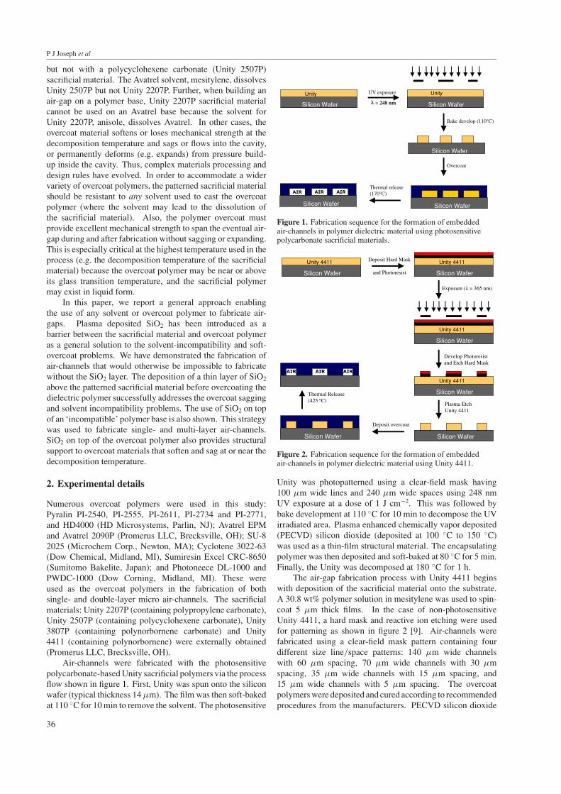
Figure 1. Fabrication sequence for the formation of embeddedair-channels in polymer dielectric material using photosensitivepolycarbonate sacrificial materials.
Silicon Wafer
Unity 4411
Silicon Wafer
Silicon Wafer
Unity 4411
Develop Photoresistand Etch Hard Mask
Plasma Etch Unity 4411
Deposit overcoat
Deposit Hard Mask
and Photoresist Silicon Wafer
Unity 4411
Exposure (λ = 365 nm)
Silicon Wafer
Unity 4411
Silicon Wafer
Unity 4411
Silicon Wafer
Thermal Release (425 oC)
Silicon Wafer
Figure 2. Fabrication sequence for the formation of embeddedair-channels in polymer dielectric material using Unity 4411.
Unity was photopatterned using a clear-field mask having100 µm wide lines and 240 µm wide spaces using 248 nmUV exposure at a dose of 1 J cm−2. This was followed bybake development at 110 ◦C for 10 min to decompose the UVirradiated area. Plasma enhanced chemically vapor deposited(PECVD) silicon dioxide (deposited at 100 ◦C to 150 ◦C)was used as a thin-film structural material. The encapsulatingpolymer was then deposited and soft-baked at 80 ◦C for 5 min.Finally, the Unity was decomposed at 180 ◦C for 1 h.
The air-gap fabrication process with Unity 4411 beginswith deposition of the sacrificial material onto the substrate.A 30.8 wt% polymer solution in mesitylene was used to spin-coat 5 µm thick films. In the case of non-photosensitiveUnity 4411, a hard mask and reactive ion etching were usedfor patterning as shown in figure 2 [9]. Air-channels werefabricated using a clear-field mask pattern containing fourdifferent size line/space patterns: 140 µm wide channelswith 60 µm spacing, 70 µm wide channels with 30 µmspacing, 35 µm wide channels with 15 µm spacing, and15 µm wide channels with 5 µm spacing. The overcoatpolymers were deposited and cured according to recommendedprocedures from the manufacturers. PECVD silicon dioxide
36
Improved fabrication of micro air-channels by incorporation of a structural barrier
(b)
(a)
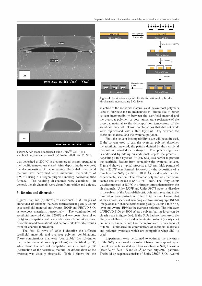
Figure 3. Air-channel fabricated using UnityTM 2207P as asacrificial polymer and overcoat: (a) Avatrel 2090P and (b) SiO2.
was deposited at 200 ◦C in a commercial system operated atthe specific temperature stated. After depositing the overcoat,the decomposition of the remaining Unity 4411 sacrificialmaterial was performed at a maximum temperature of425 ◦C using a nitrogen-purged Lindberg horizontal tubefurnace. The resulting air-channels were examined. Ingeneral, the air-channels were clean from residue and defects.
3. Results and discussion
Figures 3(a) and (b) show cross-sectional SEM images ofembedded air-channels that were fabricated using Unity 2207Pas a sacrificial material and Avatrel 2090P and PECVD SiO2
as overcoat materials, respectively. The combination ofsacrificial material (Unity 2207P) and overcoats (Avatrel orSiO2) are compatible with each other (no solvent interferenceor mechanical deformation), and demonstrate favorable resultsfrom air-channel fabrication.
The first 13 rows of table 1 describe the differentsacrificial materials and overcoat polymer combinations.Those combinations that were ‘compatible’ (no solvent orthermal/mechanical property problems) are identified by ‘G’,while those that are not compatible are identified by ‘B’(destruction of the sacrificial material or deformation of theovercoat was visually observed). Table 1 shows that the
Silicon Wafer
Unity 2207P
Silicon Wafer
Silicon Wafer
Unity 2207P
Bake develop (110°C)
PECVD SiO2
UV exposure
λ = 248 nm
Silicon Wafer
Thermal release (170°C)
Silicon WaferSilicon Wafer
AIR AIR AIR
Overcoat
Figure 4. Fabrication sequence for the formation of embeddedair-channels incorporating SiO2 layer.
selection of the sacrificial materials and the overcoat polymersused to fabricate the microchannels is limited due to eithersolvent incompatibility between the sacrificial material andthe overcoat polymer, or poor temperature resistance of theovercoat material to the decomposition temperature of thesacrificial material. Those combinations that did not workwere reprocessed with a thin layer of SiO2 between thesacrificial material and the overcoat polymer.
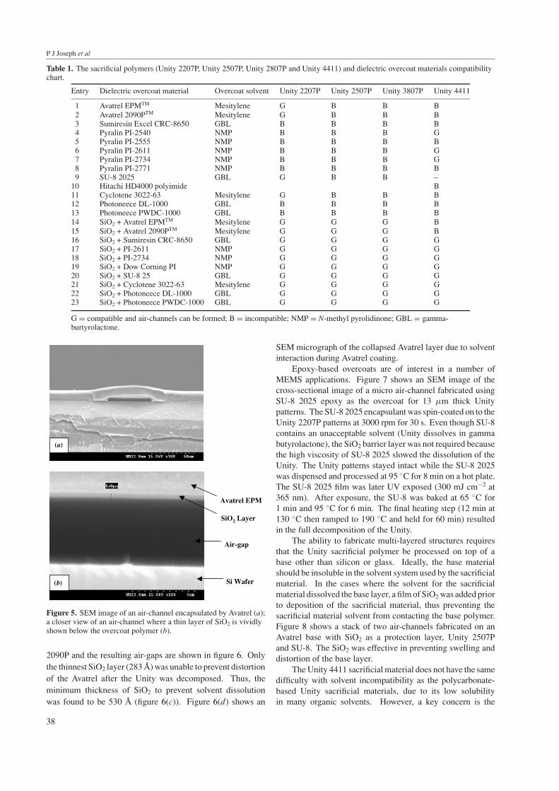
First, the solvent incompatibility issue will be addressed.If the solvent used to cast the overcoat polymer dissolvesthe sacrificial material, the pattern defined by the sacrificialmaterial is distorted or destroyed. This processing issueis addressed by adding an additional step to the process—depositing a thin layer of PECVD SiO2 as a barrier to preventthe sacrificial feature from contacting the overcoat solvent.Figure 4 shows a typical process: a 4.5 µm thick pattern ofUnity 2207P was formed, followed by the deposition of athin layer of SiO2 (∼100 to 1000 A), as described in theexperimental section. The overcoat polymer was then spin-coated and soft-baked at 85 ◦C for 10 min. The Unity 2207Pwas decomposed at 180 ◦C in a nitrogen atmosphere to form theair-channels. Unity 2507P and Unity 3807P patterns dissolvein the solvent of the Avatrel dielectric polymers, resulting in theremoval or gross distortion of the Unity pattern. Figure 5(a)shows a cross-sectional scanning electron micrograph (SEM)image of an air-channel formed using Unity 2507P, a thin SiO2
layer and Avatrel EPM as the overcoat polymer. The thin layerof PECVD SiO2 (∼4000 A) as a solvent barrier layer can beclearly seen in figure 5(b). If the SiO2 had not been used, theUnity would have dissolved in the Avatrel solvent (mesitylene)and no air-channel would have been produced. Rows 14 to 23of table 1 summarize the combinations of sacrificial materialsand polymer overcoats which are compatible when SiO2 isused.
Experiments were performed to optimize the thicknessof the SiO2 when used as a solvent barrier and support layer.Samples were fabricated with four variations in SiO2 thickness(1023 A, 790 A, 530 A and 283 A) on the Unity 2507P patterns.The build-up sequence consists of: Unity 2507P–SiO2–Avatrel
37
P J Joseph et al
Table 1. The sacrificial polymers (Unity 2207P, Unity 2507P, Unity 2807P and Unity 4411) and dielectric overcoat materials compatibilitychart.
Entry Dielectric overcoat material Overcoat solvent Unity 2207P Unity 2507P Unity 3807P Unity 4411
1 Avatrel EPMTM Mesitylene G B B B2 Avatrel 2090PTM Mesitylene G B B B3 Sumiresin Excel CRC-8650 GBL B B B B4 Pyralin PI-2540 NMP B B B G5 Pyralin PI-2555 NMP B B B B6 Pyralin PI-2611 NMP B B B G7 Pyralin PI-2734 NMP B B B G8 Pyralin PI-2771 NMP B B B B9 SU-8 2025 GBL G B B –
10 Hitachi HD4000 polyimide B11 Cyclotene 3022-63 Mesitylene G B B B12 Photoneece DL-1000 GBL B B B B13 Photoneece PWDC-1000 GBL B B B B14 SiO2 + Avatrel EPMTM Mesitylene G G G B15 SiO2 + Avatrel 2090PTM Mesitylene G G G B16 SiO2 + Sumiresin CRC-8650 GBL G G G G17 SiO2 + PI-2611 NMP G G G G18 SiO2 + PI-2734 NMP G G G G19 SiO2 + Dow Corning PI NMP G G G G20 SiO2 + SU-8 25 GBL G G G G21 SiO2 + Cyclotene 3022-63 Mesitylene G G G G22 SiO2 + Photoneece DL-1000 GBL G G G G23 SiO2 + Photoneece PWDC-1000 GBL G G G G
G = compatible and air-channels can be formed; B = incompatible; NMP = N-methyl pyrolidinone; GBL = gamma-burtyrolactone.
SiO2 Layer
Avatrel EPM
Air-gap
Si Wafer(b)
(a)
Figure 5. SEM image of an air-channel encapsulated by Avatrel (a);a closer view of an air-channel where a thin layer of SiO2 is vividlyshown below the overcoat polymer (b).
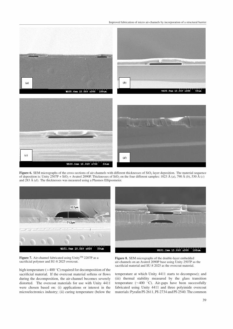
2090P and the resulting air-gaps are shown in figure 6. Onlythe thinnest SiO2 layer (283 A) was unable to prevent distortionof the Avatrel after the Unity was decomposed. Thus, theminimum thickness of SiO2 to prevent solvent dissolutionwas found to be 530 A (figure 6(c)). Figure 6(d) shows an
SEM micrograph of the collapsed Avatrel layer due to solventinteraction during Avatrel coating.
Epoxy-based overcoats are of interest in a number ofMEMS applications. Figure 7 shows an SEM image of thecross-sectional image of a micro air-channel fabricated usingSU-8 2025 epoxy as the overcoat for 13 µm thick Unitypatterns. The SU-8 2025 encapsulant was spin-coated on to theUnity 2207P patterns at 3000 rpm for 30 s. Even though SU-8contains an unacceptable solvent (Unity dissolves in gammabutyrolactone), the SiO2 barrier layer was not required becausethe high viscosity of SU-8 2025 slowed the dissolution of theUnity. The Unity patterns stayed intact while the SU-8 2025was dispensed and processed at 95 ◦C for 8 min on a hot plate.The SU-8 2025 film was later UV exposed (300 mJ cm−2 at365 nm). After exposure, the SU-8 was baked at 65 ◦C for1 min and 95 ◦C for 6 min. The final heating step (12 min at130 ◦C then ramped to 190 ◦C and held for 60 min) resultedin the full decomposition of the Unity.
The ability to fabricate multi-layered structures requiresthat the Unity sacrificial polymer be processed on top of abase other than silicon or glass. Ideally, the base materialshould be insoluble in the solvent system used by the sacrificialmaterial. In the cases where the solvent for the sacrificialmaterial dissolved the base layer, a film of SiO2 was added priorto deposition of the sacrificial material, thus preventing thesacrificial material solvent from contacting the base polymer.Figure 8 shows a stack of two air-channels fabricated on anAvatrel base with SiO2 as a protection layer, Unity 2507Pand SU-8. The SiO2 was effective in preventing swelling anddistortion of the base layer.
The Unity 4411 sacrificial material does not have the samedifficulty with solvent incompatibility as the polycarbonate-based Unity sacrificial materials, due to its low solubilityin many organic solvents. However, a key concern is the
38
Improved fabrication of micro air-channels by incorporation of a structural barrier
(a) (b)
(d)(c)
Figure 6. SEM micrographs of the cross-sections of air-channels with different thicknesses of SiO2 layer deposition. The material sequenceof deposition is: Unity 2507P + SiO2 + Avatrel 2090P. Thicknesses of SiO2 on the four different samples: 1023 A (a), 790 A (b), 530 A (c)and 283 A (d). The thicknesses was measured using a Plasmos Ellipsometer.
Figure 7. Air-channel fabricated using UnityTM 2207P as asacrificial polymer and SU-8 2025 overcoat.
high temperature (>400 ◦C) required for decomposition of thesacrificial material. If the overcoat material softens or flowsduring the decomposition, the air-channel becomes severelydistorted. The overcoat materials for use with Unity 4411were chosen based on: (i) applications or interest in themicroelectronics industry; (ii) curing temperature (below the
Figure 8. SEM micrographs of the double-layer embeddedair-channels on an Avatrel 2090P base using Unity 2507P as thesacrificial material and SU-8 2025 as the overcoat material.
temperature at which Unity 4411 starts to decompose); and(iii) thermal stability measured by the glass transitiontemperature (∼400 ◦C). Air-gaps have been successfullyfabricated using Unity 4411 and three polyimide overcoatmaterials: Pyralin PI-2611, PI-2734 and PI-2540. The common
39

P J Joseph et al
(a) (b)
(c) (d )
Figure 9. SEM images of features following the decomposition of 5 µm Unity 4411 overcoated with PI-2771 overcoat polyimide andchannel widths of (a) 140 µm, (b) 70 µm, (c) 35 µm and (d) 15 µm.
factor between these polyimides is a high Tg (>350 ◦C).Several other polyimides, including PI-2555, PI-2771 andHD4000, sag into the channel during the decomposition,except in the case of small channels with a width of less than15 µm. The Tg of PI-2555 is >320 ◦C, the Tg of PI-2771 is294 ◦C, and the Tg of HD4000 is 350 ◦C. Figures 9(a)–(d)show SEM cross-sections of various sized features from a5 µm thick Unity 4411 film overcoated with PI-2771 anddecomposed. Only the smallest width features produced air-channels, as shown in figure 9(d). Some remaining sacrificialmaterial is seen in the corners of the channels in figures 9(a)–(c) from incomplete decomposition. Identical results toPI-2771 are seen using either HD4000 or PI-2555 as theovercoat material. The other overcoat materials listed in thefirst 13 rows of table 1 do not work for any dimensions due topoor thermal stability.
The reason polymer overcoats fail with Unity 4411 hasbeen attributed to a loss in mechanical properties or flow ofthe polymer when the overcoat polymer passes through theTg. As the Unity 4411 decomposes, it passes through a liquid-like stage. If the overcoat material is above its Tg, surfacetension can pull it into the channel as the sacrificial materialdecomposes. One approach to mitigating this problem is toadd a thin layer of SiO2 as a rigid support layer either betweenthe sacrificial and overcoat polymers or on top of the overcoatpolymer layer.
Sample sets were fabricated with SiO2 between thesacrificial material and the overcoat, and SiO2 above theovercoat material: (i) overcoat polymer only; (ii) 5000 A ofSiO2 + overcoat polymer; (iii) overcoat polymer + 5000 ASiO2; and (iv) overcoat polymer + 2 µm of SiO2. Theovercoat polymer in sample sets (iii) and (iv), with SiO2
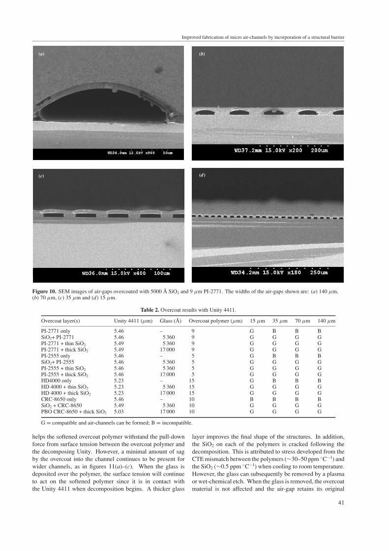
on top of the polymer, was cured before deposition of theglass. A summary of the results for the various sized air-gap structures and overcoat combinations with Unity 4411is given in table 2. A 5000 A layer of SiO2 depositedbetween the sacrificial material and the overcoat polymercorrects the problem with the overcoat collapsing or fillingthe channel. Figures 10(a)–(d) show cross-sectional SEMimages of various sized structures overcoated with SiO2 and PI-2771. Some of the resulting air-cavities are dome-shaped. Theamount of the overcoat deformation and the height of theresulting channel increases with increasing channel width.The results for PI-2555 are similar to those for PI-2771, exceptthe structures with SiO2 and PI-2555 deformed less. Manyof the air-channels were rectangular. However, even in thecases where the resulting air-channel had a dome-shaped crosssection, the glass layer is visibly intact. Figure 11 shows SEMimages of air-channels fabricated with Unity 4411 overcoatedwith PI-2771, then a SiO2 layer on the top surface. Glassthicknesses of 5000 A and 2 µm are demonstrated. Whenthe glass is above the overcoat polymer, the additional support
40
Improved fabrication of micro air-channels by incorporation of a structural barrier
(d)
(a)
(d )
(b)
(c)
Figure 10. SEM images of air-gaps overcoated with 5000 A SiO2 and 9 µm PI-2771. The widths of the air-gaps shown are: (a) 140 µm,(b) 70 µm, (c) 35 µm and (d) 15 µm.
Table 2. Overcoat results with Unity 4411.
Overcoat layer(s) Unity 4411 (µm) Glass (A) Overcoat polymer (µm) 15 µm 35 µm 70 µm 140 µm
PI-2771 only 5.46 – 9 G B B BSiO2+ PI-2771 5.46 5 360 9 G G G GPI-2771 + thin SiO2 5.49 5 360 9 G G G GPI-2771 + thick SiO2 5.49 17 000 9 G G G GPI-2555 only 5.46 – 5 G B B BSiO2+ PI-2555 5.46 5 360 5 G G G GPI-2555 + thin SiO2 5.46 5 360 5 G G G GPI-2555 + thick SiO2 5.46 17 000 5 G G G GHD4000 only 5.23 – 15 G B B BHD 4000 + thin SiO2 5.23 5 360 15 G G G GHD 4000 + thick SiO2 5.23 17 000 15 G G G GCRC-8650 only 5.46 – 10 B B B BSiO2 + CRC-8650 5.49 5 360 10 G G G GPBO CRC-8650 + thick SiO2 5.03 17 000 10 G G G G
G = compatible and air-channels can be formed; B = incompatible.
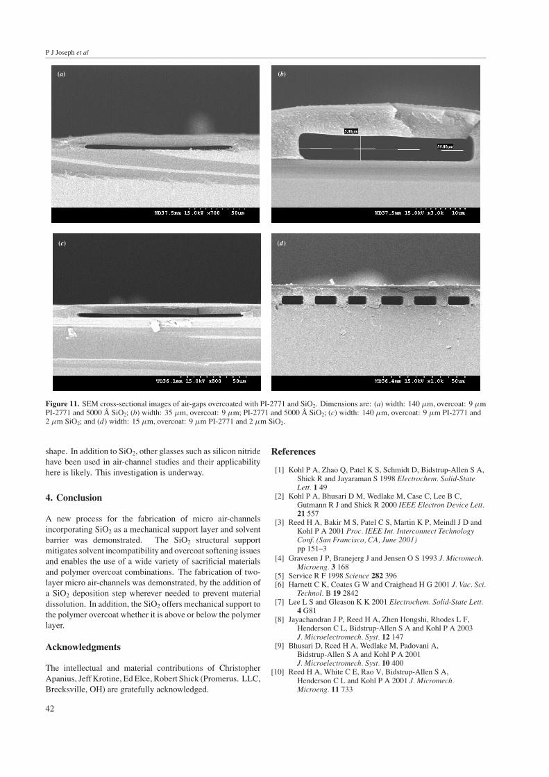
helps the softened overcoat polymer withstand the pull-downforce from surface tension between the overcoat polymer andthe decomposing Unity. However, a minimal amount of sagby the overcoat into the channel continues to be present forwider channels, as in figures 11(a)–(c). When the glass isdeposited over the polymer, the surface tension will continueto act on the softened polymer since it is in contact withthe Unity 4411 when decomposition begins. A thicker glass
layer improves the final shape of the structures. In addition,the SiO2 on each of the polymers is cracked following thedecomposition. This is attributed to stress developed from theCTE mismatch between the polymers (∼30–50 ppm ◦C−1) andthe SiO2 (∼0.5 ppm ◦C−1) when cooling to room temperature.However, the glass can subsequently be removed by a plasmaor wet-chemical etch. When the glass is removed, the overcoatmaterial is not affected and the air-gap retains its original
41
P J Joseph et al
(a) (b)
(c) (d )
Figure 11. SEM cross-sectional images of air-gaps overcoated with PI-2771 and SiO2. Dimensions are: (a) width: 140 µm, overcoat: 9 µmPI-2771 and 5000 A SiO2; (b) width: 35 µm, overcoat: 9 µm; PI-2771 and 5000 A SiO2; (c) width: 140 µm, overcoat: 9 µm PI-2771 and2 µm SiO2; and (d) width: 15 µm, overcoat: 9 µm PI-2771 and 2 µm SiO2.
shape. In addition to SiO2, other glasses such as silicon nitridehave been used in air-channel studies and their applicabilityhere is likely. This investigation is underway.
4. Conclusion
A new process for the fabrication of micro air-channelsincorporating SiO2 as a mechanical support layer and solventbarrier was demonstrated. The SiO2 structural supportmitigates solvent incompatibility and overcoat softening issuesand enables the use of a wide variety of sacrificial materialsand polymer overcoat combinations. The fabrication of two-layer micro air-channels was demonstrated, by the addition ofa SiO2 deposition step wherever needed to prevent materialdissolution. In addition, the SiO2 offers mechanical support tothe polymer overcoat whether it is above or below the polymerlayer.
Acknowledgments
The intellectual and material contributions of ChristopherApanius, Jeff Krotine, Ed Elce, Robert Shick (Promerus. LLC,Brecksville, OH) are gratefully acknowledged.
References
[1] Kohl P A, Zhao Q, Patel K S, Schmidt D, Bidstrup-Allen S A,Shick R and Jayaraman S 1998 Electrochem. Solid-StateLett. 1 49
[2] Kohl P A, Bhusari D M, Wedlake M, Case C, Lee B C,Gutmann R J and Shick R 2000 IEEE Electron Device Lett.21 557
[3] Reed H A, Bakir M S, Patel C S, Martin K P, Meindl J D andKohl P A 2001 Proc. IEEE Int. Interconnect TechnologyConf. (San Francisco, CA, June 2001)pp 151–3
[4] Gravesen J P, Branejerg J and Jensen O S 1993 J. Micromech.Microeng. 3 168
[5] Service R F 1998 Science 282 396[6] Harnett C K, Coates G W and Craighead H G 2001 J. Vac. Sci.
Technol. B 19 2842[7] Lee L S and Gleason K K 2001 Electrochem. Solid-State Lett.
4 G81[8] Jayachandran J P, Reed H A, Zhen Hongshi, Rhodes L F,
Henderson C L, Bidstrup-Allen S A and Kohl P A 2003J. Microelectromech. Syst. 12 147
[9] Bhusari D, Reed H A, Wedlake M, Padovani A,Bidstrup-Allen S A and Kohl P A 2001J. Microelectromech. Syst. 10 400
[10] Reed H A, White C E, Rao V, Bidstrup-Allen S A,Henderson C L and Kohl P A 2001 J. Micromech.Microeng. 11 733
42


![Improved conductivity and capacitance of interdigital ...mai.group.whut.edu.cn/chs/lw/2016/201702/P... · polymer fabrication techniques with pyrolysis or thermal degradation [21–27].](https://static.fdocuments.net/doc/165x107/5ff7dcadced30417a4176688/improved-conductivity-and-capacitance-of-interdigital-maigroupwhuteducnchslw2016201702p.jpg)