IMPROVED DESIGN OF A F ALLING -FIL M TUB ULAR … Distributor_2016.11.30_ver2.pdfSugar plant...
33
www.isgec.com Slide 1 Isgec Heavy Engineering Ltd, Noida, India Sanjay Awasthi At : 29 th ISSCT Congress, Chiang Mai, , Thailand, 7 Dec 2016 IMPROVED DESIGN OF A FALLING-FILM TUBULAR EVAPORATOR WITH MAINTENANCE-FRIENDLY NOVEL JUICE DISTRIBUTOR Speaker FE2:
Transcript of IMPROVED DESIGN OF A F ALLING -FIL M TUB ULAR … Distributor_2016.11.30_ver2.pdfSugar plant...

www.isgec.com Slide 1
Isgec Heavy Engineering Ltd,
Noida, India
Sanjay Awasthi
At : 29th ISSCT Congress, Chiang Mai, , Thailand, 7 Dec 2016
IMPROVED DESIGN OF A
FALLING-FILM
TUBULAR EVAPORATOR WITH MAINTENANCE-FRIENDLY NOVEL JUICE DISTRIBUTOR
Speaker
FE2:

www.isgec.com Slide 2
D.K. Goel
Adviser
Sanjay Awasthi
Business Head
Rajesh Srivastava
General Manager (Design)
AUTHORS
Sugar Machinery Division,
ISGEC Heavy Engineering Ltd, Noida, India

www.isgec.com Slide 3
BACKGROUND
© I
BE
ES
• There are about 550 operating sugar factories in India,
out of these, 70 are backend refineries and 6 are
standalone refineries.
• Almost 40% sugar factories including sugar refineries
are using falling film tubular evaporators with tube size
35/45 mm & tube length ranging 8.0 m to 12.0 m.
• Worldwide about 300 sugar factories and refineries are
working with various design of falling film evaporators.
• Isgec has developed an improved design of falling
film evaporator with a Novel juice distributor.
www.isgec.com Slide 4
© I
BE
ES
• We all know that juice distributor is the most important
part of FFE. A faulty design can be a disaster, leading to
chocking of tubes due to caramelisation of sugar, which is
a huge sugar & efficiency loss.
This presentation gives details of the novel juice distributor,
that is the one of its kind design, which provides
100% distribution of juice in tubes and also takes care of
maintainability by providing sufficient head room between
top tube sheet and juice distributor.
BACKGROUND

www.isgec.com Slide 5
OBJECTIVE
OF THE STUDY
• To develop a reliable and maintenance friendly
juice distributor for falling film tubular evaporator.
• To develop sturdy, reliable and thermally stable
design of long tube falling film evaporator vessel.

www.isgec.com Slide 6
CONVENTIONAL DISTRIBUTOR
DRAWBACKS
• Conventional distributors are prone to
tube choking due to uneven distribution
of juice.
• Absence of head-room between top tube
sheet and juice distributor, necessitates
its dismantling for mechanical de-scaling
of tubes
Hence there has been a need
for a reliable and maintenance
friendly new juice distributor.

www.isgec.com Slide 7
CONVENTIONAL
DISTRIBUTOR
TUBE CHOCKING
Chocked Tubes

www.isgec.com Slide 8
NOVEL JUICE
DISTRIBUTOR

www.isgec.com Slide 9
NOVEL JUICE DISTRIBUTOR:
INTERNAL 3D VIEW
Inlet weir box
Cascade distributor
Segmented
tray plate Click for video
www.isgec.com Slide 10
NOVEL JUICE
DISTRIBUTOR: FEATURES
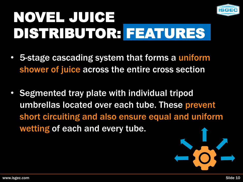
• 5-stage cascading system that forms a uniform
shower of juice across the entire cross section
• Segmented tray plate with individual tripod
umbrellas located over each tube. These prevent
short circuiting and also ensure equal and uniform
wetting of each and every tube.
www.isgec.com Slide 11
NOVEL JUICE DISTRIBUTOR:
FEATURES
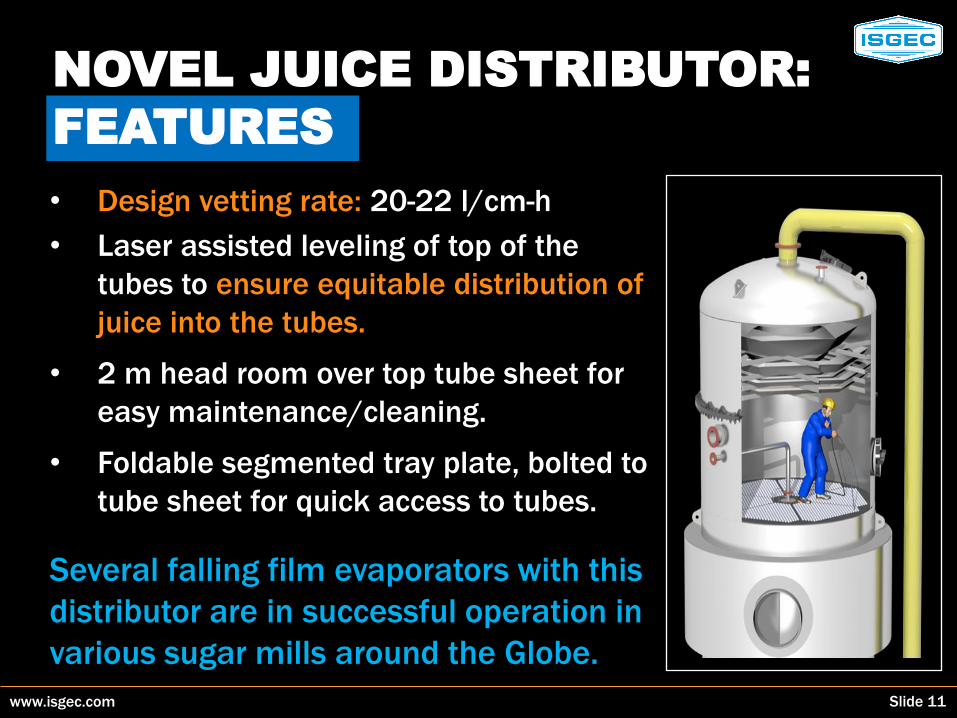
• Design vetting rate: 20-22 l/cm-h
• Laser assisted leveling of top of the
tubes to ensure equitable distribution of
juice into the tubes.
• 2 m head room over top tube sheet for
easy maintenance/cleaning.
• Foldable segmented tray plate, bolted to
tube sheet for quick access to tubes.
Several falling film evaporators with this
distributor are in successful operation in
various sugar mills around the Globe.

www.isgec.com Slide 12
INSTALLATIONS OF FFE
NOVEL JUICE DISTRIBUTOR
Sugar plant capacity : 5400 TCD
Location : Agrolmos, Peru
Configuration : Quintuple
HSA of FFE : m2 3500/3500/
3500/1200/800
with 1 spare of each size

www.isgec.com Slide 13
Sugar plant capacity: 12000 TCD
Location: Jawahar SSK, India
HSA of FFE : 2 x 6000 m2
(The largest FFE in India)
INSTALLATIONS OF FFE
NOVEL JUICE DISTRIBUTOR
www.isgec.com Slide 14
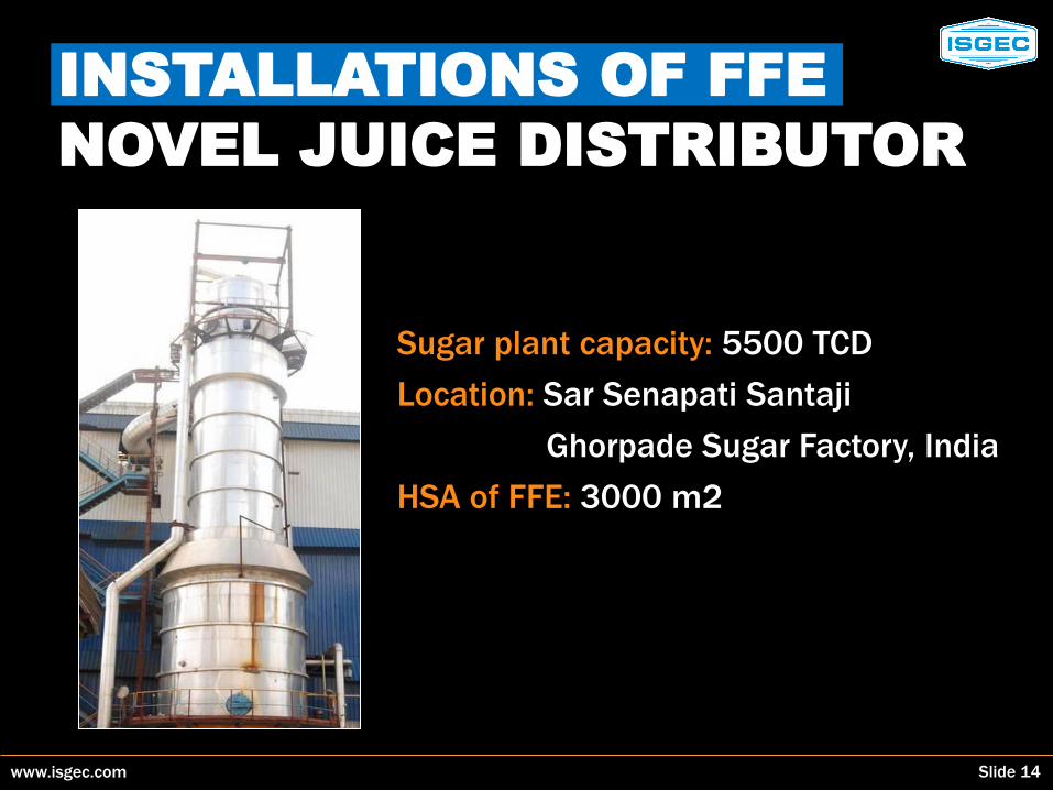
Sugar plant capacity: 5500 TCD
Location: Sar Senapati Santaji
Ghorpade Sugar Factory, India
HSA of FFE: 3000 m2
INSTALLATIONS OF FFE
NOVEL JUICE DISTRIBUTOR

www.isgec.com Slide 15
Sugar plant capacity: 6000 TCD
Location: KPR sugar, India
HSA of FFE: 4 x 3000 m2
INSTALLATIONS OF FFE
www.isgec.com Slide 16
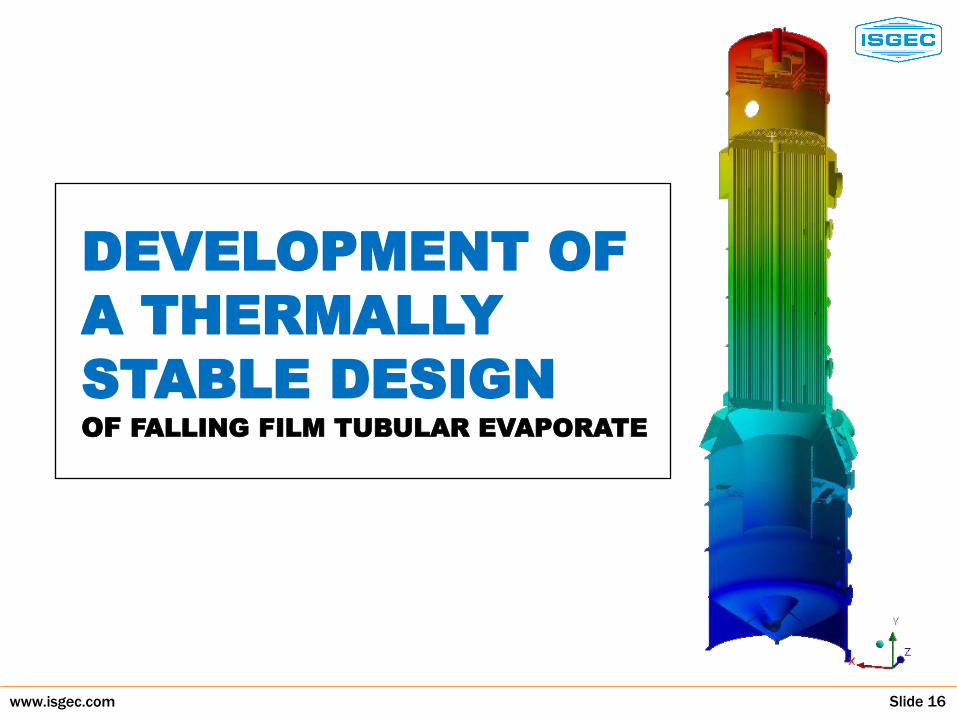
DEVELOPMENT OF
A THERMALLY
STABLE DESIGN OF FALLING FILM TUBULAR EVAPORATE

www.isgec.com Slide 17
THERMAL STABILITY:
BACKGROUND
Falling film evaporator generally comprise of carbon
steel calandria fitted with 10 /12 m long austenitic
grade SS 304 or ferritic grade SS 439 tubes.
• Coeff. of linear expansion of SS 304 is 1.43 times
that of carbon steel resulting in higher thermal
stresses, particularly at temp. 100-1200C.
• Coefficient of linear expansion of SS 439 is 0.87
times that of carbon steel and hence the thermal
stress are much lower even at temp. 100-1200C
www.isgec.com Slide 18
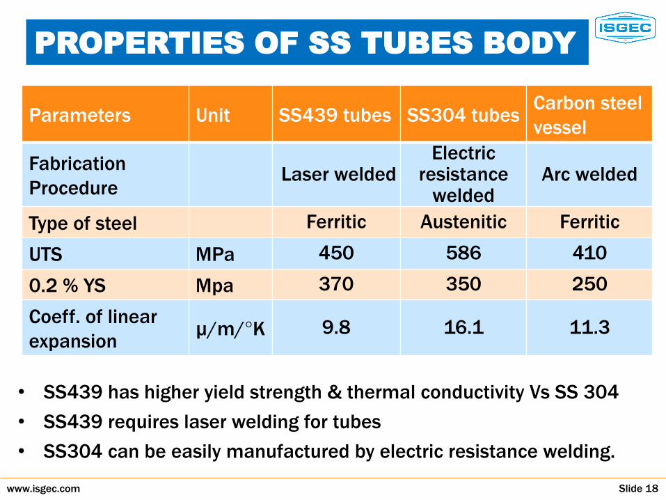
PROPERTIES OF SS TUBES BODY
• SS439 has higher yield strength & thermal conductivity Vs SS 304
• SS439 requires laser welding for tubes
• SS304 can be easily manufactured by electric resistance welding.
Parameters Unit SS439 tubes SS304 tubes Carbon steel
vessel
Fabrication
Procedure Laser welded
Electric resistance
welded Arc welded
Type of steel Ferritic Austenitic Ferritic
UTS MPa 450 586 410
0.2 % YS Mpa 370 350 250
Coeff. of linear
expansion µ/m/°K 9.8 16.1 11.3
www.isgec.com Slide 19
THERMAL STRESS
ANALYSIS: ASSUMPTIONS • The 1st effect of evaporator is subjected to the highest thermal
and pressure loading so we selected 1st effect with 10 m long,
45 mm dia tubes for study.
• Solid works software version 2016 and ANSYS Workbench R15
software were used for the 3D modeling and thermal stress
analysis, respectively.
• The assembly is constrained (fixed) at bottom support
skirt. The pressure and temperature were applied
simultaneously in full body
• Thermal stress analysis is carried out for 2 grades of
SS tubes i.e. 439 and 304, fitted in carbon steel calandria
without expansion joints in the calandria shell.

www.isgec.com Slide 20
THERMAL STRESS ANALYSIS:
OPERATING PARAMETER
• Tube side pressure 2.2 bar (a)
and temp. 115°C
• Shell side pressure 2.8 bar (a)
and temp. 130°C
• Ambient temp. 30°C

www.isgec.com Slide 21
THERMAL STRESS
ANALYSIS:
DETAIL OF ITERATIONS
Three iterations were done for FEA of falling film evap.
• Assembly with tubes at the time of hydro test
• Assembly with 304 tubes at operating parameter
• Assembly with 439 tubes at operating parameter
Outputs of stress values and deflection pattern in
respect of following are shown in subsequent slides
• Top tube sheet
• Tube bundle
• Complete assembly of the evaporator vessel

www.isgec.com Slide 22
THERMAL STRESS
ANALYSIS : TUBE PLATE
B: Static-SS304 Equivalent Stress Type: Equivalent (von-Mises) Stress Unit: MPa Time: 1 Custom Max: 187.46 Min: 4.0106 04-03-2016 13:05
187.46 125 109.88 94.753 79.629 64.505 49.382 34.258 19.134 4.0106
ANSYS R15.0
0.00 500.00 1000.00(mm)
250.00 750.00
Top tube sheet with SS 304
tubes in hot condition
B: Static-SS304 Equivalent Stress Type: Equivalent (von-Mises) Stress Unit: MPa Time: 1 Custom Max: 42.153 Min: 0.2357 16-01-2016 11:18
42.153 37.495 32.838 28.18 23.523 18.865 14.207 9.549 4.892 0.2357
ANSYS R15.0
0.00 500.00 1000.00(mm)
250.00 750.00
Top tube sheet with SS 304
tubes in cold condition

www.isgec.com Slide 23
THERMAL STRESS
ANALYSIS : TUBE PLATE
B: Static-SS304 Equivalent Stress Type: Equivalent (von-Mises) Stress Unit: MPa Time: 1 Custom Max: 42.153 Min: 0.2357 01-03-2016 11:03
42.153 37.495 32.838 28.18 23.523 18.865 14.207 9.549 4.892 0.2357
B: Static-SS439 Equivalent Stress Type: Equivalent (von-Mises) Stress Unit: MPa Time: 1 Custom Max: 520.29 Min: 0.00078125 04-03-2016 13:04
520.29 125 109.38 93.75 78.125 62.5 46.875 31.251 15.626 0.00078125
ANSYS R15.0
ANSYS R15.0
0.00 500.00 1000.00(mm)
250.00 750.00
0.00 500.00 1000.00(mm)
250.00 750.00
Top tube sheet with SS 409 tubes
in cold condition
Top tube sheet with SS 439 tubes
in hot condition

www.isgec.com Slide 24
THERMAL STRESS
ANALYSIS: TUBE PLATE
• At cold condition i.e. hydro test, stress in top tube sheet is only
35-40 Mpa.
• Once the FFTE vessel is subjected to the operating
temperature conditions, the stress level in the tube sheets
increases substantially due to the difference in the coefficient
of linear expansion between the calandria and the tubes.
• At the operating pressure and temperature conditions, the top
tube sheet (assembled with SS 304 tubes) develops a stress
level of 130-150 MPa, which decreases to 100-120 MPa for
tube sheet (assembled with SS 439 tubes).

www.isgec.com Slide 25
THERMAL STRESS
ANALYSIS : TUBE BUNDLE
Deflection of tube bundle at operating parameter
SS 304 SS 439
0 4e + 0 α 3 (mm)
2e +003
0 2.5e+003 5e+003 (mm)
1.25e+003 3.75e+003

www.isgec.com Slide 26
• For the SS 304 tube bundle, all the tubes have buckled-in to
cater the relatively lower expansion of carbon steel calandria
shell.
• However, for the SS 439 tube bundle, the tube sheets have
sagged inwards marginally and the outer periphery tubes
have followed the shell expansion.
• At the hydro-test condition, the stress in the tubes is only
6-12 MPa. At the operating conditions, SS 304 tubes develop
a stress of 65-130 MPa, which decreases to 30-50 MPa if
the tubes are SS 439.
THERMAL STRESS
ANALYSIS : TUBE BUNDLE

www.isgec.com Slide 27
THERMAL STRESS
ANALYSIS : ASSEMBLY Stress/deflection of assly at operating parameter
ANSYS R15.0
ANSYS R15.0
B: Static-SS439
Equivalent Stress
Type: Equivalent (von-Mises) Stress
Unit: MPa
Time: 1
Custom
Max: 235.29
Min: 0.00078125
04-03-2016 13:04
235.29 125 109.38 93.75 78.125 62.5 46.875 31.251 15.626 0.00078125
C: Static – SS739
Total Deformation
Unit: mm
Time: 1
Custom
Max: 27.24
Min: 0
04-03-2016 12:48
27.24 24.213 21.187 18.16 15.133 12.107 9.0799 6.0533 3.0266 0
Stress pattern:
SS 439
Deflection
pattern: SS 439 0 9e + 003 (mm)
4.5e +003
0 4e + 003 (mm)
2e +003

www.isgec.com Slide 28
SUMMARY OF
FEA RESULTS
*Study shows that at operating parameters, use of 304 tubes
results in stress level higher than desired 1.5 to 1.6 safety
factor and hence requires corrective action in design.
Description Unit Iteration-1 Hydro test
Iteration-2 SS 304
tube
Iteration-3 SS 439
tube
Max. stress in top tube sheet
MPa 35-40 130-150 100-120
Max. stress in SS tubes
Mpa 6-12 65-130 30-50
Max. stress in Evap. Body
Mpa 90-100 165-175* 140-150

www.isgec.com Slide 29
DESIGN IMPROVEMENT
FOR FFE WITH SS304 TUBE
• Sugar mills in most of countries prefer SS304 tubes because of easy availability from local supplier.
• For such requirement, we have improved the design of the carbon steel calandria by incorporating an expansion joint, to reduce the thermal stresses arising out of vastly dissimilar linear expansions between tubes and calandria.

www.isgec.com Slide 30
INSTALLATIONS WITH
SS 439 FERRITIC TUBES
Sugar plant capacity: 24000 TCD
Location: WNSC, Sudan
Configuration: 5 quintuple sets
HSA of FFE: m2 3340/1200

www.isgec.com Slide 31
CONCLUSION: NOVEL
JUICE DISTRIBUTOR
• Ensures uniform wetting of each and every tube.
• The cascade juice distributor, once assembled
inside the FFE vessel, need not be disturbed or
dismantled even during the off-season.
• As there is no need to dismantle the
juice distributor, this facilitates faster
mechanical de-scaling during the crop.

www.isgec.com Slide 32
CONCLUSION: THERMALLY
STABLE DESIGN
• The tubes and the tube sheets of a falling film evaporator fitted
with SS 439 tubes, are subjected to 25% lower stresses.
• Falling film evaporators with SS 439 tubes installed in a green field
24,000 TCD sugar plant in Sudan, have completed 4 crushing
seasons without any tube failure or structural deformity.
• Falling film evaporators with SS304 tubes and
expansion joint in carbon steel calandria shell, are
also working satisfactorily in several installations.
• FFE with SS304 calandria as well as tubes for sugar
refineries, have no problem of thermal stress. Such
FFE are working in a sugar refinery in Mexico
supplied by ISGEC.
Click for video

www.isgec.com Slide 33
Thank You Presented By
Isgec Heavy Engineering Ltd, Noida, India