
Improved Bypass and Collection System for … 3 feet in diameter), refer red to as the Wagner horn...
5
MFR PAPER 1256 Improved Bypass and Collection System for Protection of Juvenile Salmon and Steel head Trout at Lower Granite Dam GENE M. MATTHEWS, GEORGE A. SWAN, and JIM ROSS SMITH ABSTRACT -A new and improved system for diverting, bypassing, and collect- ing juvenile salmon, Oncorhynchus sp., and steelhead trout, Salmo Gairdneri, at Lower Granite Dam on the lower Snake River is described. Major changes from previous systems of this type include a special fish screen slot for placement of the improved traveling screen, an open gallery bypass system for routing fish around the turbines, and a collection and holding area totally supplied by gravity-flow. The system is currently being evaluated by the National Marine Fisheries Service under contract to the U. S. Army Corps of Engineers. INTRODUCTION The National Marine Fisheries Ser- vice is conducting resear ch on improv- ing survival of juvenile Pacific salmon, genus Oncorhync hus, and steel he ad trout , Sa /rna gairdneri , during their downstream migration . A major por- tion of the res earch emphasize s the de- velopment of safe diver sion, by pass, and c ollection systems at dams on the Columbia and Snake Rivers in the Pacific Northwe st (Fig. I) . Smith and Fan (1975 ) described a bypass and col- lection sys tem for Little Goose Dam on the Snake River that utilized traveling screens in turbine intakes, submerged orifices in turbine intake gatewells , and an en closed fi sh-transport pipe between the gateweJls and the holding facilit y . This system was evaluated from 1971 through 1973, and the improvement s were incorporated into the de sign of a similar facility at Lower Granite Dam (recentl y constructed 30 miles up- stream from Little Goo se Dam). This report describe s further improvements and modifications, designed to provide Gene M. Matthews, George A. Swan, and Jim Ross Smith are with the Northwest and Alaska Fisheries Center, National Marine Fisheries Service, NOAA , 2725 Montlake Blvd. East, Seattle, WA 98112. 10 safer and more effic ient handling and movement of fish, at the Lower Granite Dam facility . FACILITIES AND IMPROVEMENTS Fish Screening Facilities The turbine intakes and g atewells of Lower Granite Dam are basically iden- tical to those of Little Goose Dam with one major exception. At Lower Gr anite Dam an addition al slot, the special fish screen slot, wa s constructed upstream from each intake bulkhe ad slot- s pecific ally for the placement of a tra veling screen (Fi g. 2) . The fish s creen slot differs from the bulkhead slot in the following fe atures: I) The fi s h s lot is closer to the en- trance of the turbine intake where the cross-sectional area is la rger and the approach velocity is less. 2) The angle of flow passing the fish screen slot is more ac ute bec ause the intake ceilin g is steeper at this point. 3) The fish screen slot is isolated from other gate slots and considerably narrower (from front to back). There- fore, no vertical barrier screen is re- quired to c onfine fingerlings. 4) A sm a ll screened opening (10 feet by 20 feet) is located a pproxima tel y 15 feet below the water s urface on the Figure I .- Map of area show ing lhe local ion s o f dams on lhe lower Columbia and Snake River s. downstream wall of the slot. Upwelling flows caused by a traveling screen in the fish s creen slot are disch arged through this screened opening and pass down- ward through three vertical shafts (ap- proximately 3 feet in diameter), refer- red to as the Wagner horn (Fig. 2), and back into the turbine intake. 5) The ceiling of the turbine intake on the upstream side of the fish screen slot is cut off horizontally, cre ating a la rger openin g into the fish screen slot than into the bu. lkhead slot when a traveling screen is installed. Standard traveling screens , such as those used at Little Goose Dam and described by Farr (1974) and by Smith and Farr (1975), are used at Lower Granite Dam without modification and operate satisfactoril y in the bulkhe ad slot but not in the fish screen slot. When tested in the fish screen slot, descaling and injur y of fingerlings increased while guiding efficiency decreased . The angle of the traveling screen in relation to the water flow in the intake was determined to be the main cause of the problem. The s tandard traveling screens operate at a fixed 45 ° angle from verti ca l, whi ch res ults in the Marine Fisheries Review
Transcript of Improved Bypass and Collection System for … 3 feet in diameter), refer red to as the Wagner horn...

MFR PAPER 1256
Improved Bypass and Collection System for Protection of Juvenile Salmon and Steel head Trout at Lower Granite Dam
GENE M. MATTHEWS, GEORGE A. SWAN, and JIM ROSS SMITH
ABSTRACT -A new and improved system for diverting, bypassing, and collecting juvenile salmon, Oncorhynchus sp., and steelhead trout, Salmo Gairdneri, at Lower Granite Dam on the lower Snake River is described. Major changes from previous systems of this type include a special fish screen slot for placement of the improved traveling screen, an open gallery bypass system for routing fish around the turbines, and a collection and holding area totally supplied by gravity-flow. The system is currently being evaluated by the National Marine Fisheries Service under contract to the U. S. Army Corps of Engineers.
INTRODUCTION
The National Marine Fisheries Service is conducting research on improving survival of juvenile Pacific salmon, genus Oncorhynchus, and steel he ad trout , Sa/rna gairdneri , during their downstream migration . A major portion of the research emphasizes the development of safe divers ion, bypass, and collection systems at dams on the Columbia and Snake Rivers in the Pacific Northwest (Fig. I) . Smith and Fan (1975 ) described a by pass and collection system for Little Goose Dam on the Snake River that utilized traveling screens in turbine intakes , submerged orifices in turbine intake gatewells , and an enc losed fi sh-transport pipe between the gateweJls and the holding facilit y . This system was evaluated from 1971 through 1973, and the improvements were incorporated into the des ign of a similar facilit y at Lower Granite Dam (recentl y constructed 30 miles upstream from Little Goose Dam). This report describes further improvements and modifications , designed to provide
Gene M. Matthews, George A. Swan, and Jim Ross Smith are with the Northwest and Alaska Fisheries Center, National Marine Fisheries Service, NOAA , 2725 Montlake Blvd. East, Seattle, WA 98112.
10
safer and more effic ient handling and movement of fish, at the Lower Granite Dam facility .
FACILITIES AND IMPROVEMENTS
Fish Screening Facilities
The turbine intakes and gatewells of Lower Granite Dam are basically identic al to those of Little Goose Dam with one major exception. At Lower Granite Dam an additiona l slot, the specia l fish screen slot, was constructed upstream from each intake bulkhe ad slots pecific a lly for the placement of a tr aveling screen (Fi g. 2) . The fish screen slot differs from the bulkhead slot in the following fe atures:
I) The fi sh s lot is closer to the entrance of the turbine intake where the cross-sectional area is larger and the approach velocity is less.
2) The angle of flow pass ing the fish sc reen slot is more ac ute because the intake ceiling is steeper at this point.
3) The fish screen slot is isol ated from other gate slots and considerably narrower (from front to back). Therefore, no vertical barrier screen is required to confine fingerlings .
4) A small screened opening (10 feet by 20 feet) is located approximatel y 15 feet below the water surface on the
Figure I .-Map of a rea show ing lhe local ion s o f dams o n lhe lower Co lumbia and Snake Rivers.
downstream wall of the slot. Upwelling flows caused by a traveling screen in the fish screen slot are discharged through this screened opening and pass downward through three vertical shafts (approximately 3 feet in diameter), referred to as the Wagner horn (Fig . 2), and bac k into the turbine intake.
5) The ceiling of the turbine intake on the upstream side of the fish screen s lot is cut off horizontally, creating a larger opening into the fish screen slot than into the bu.lkhead slot when a traveling screen is installed.
Standard traveling screens , such as those used at Little Goose Dam and described by Farr (1974) and by Smith and Farr (1975), are used at Lower Granite Dam without modification and operate satisfactorily in the bulkhead slot but not in the fish screen slot. When tested in the fish screen slot, descaling and injury of fingerlings increased while guiding efficiency decreased . The angle of the traveling screen in relation to the water flow in the intake was determined to be the main cause of the problem. The standard traveling screens operate at a fixed 45° angle from verti ca l, whic h res ults in the
Marine Fisheries Review

Foreboy
Traveling screen
Figure 2 .-Cross sectional view of turbine intake at Lower Granite Dam indicating principal fe atures of the bypass system . Note that traveling screen is shown in the bulkhead slo t but it can be placed in the fi sh screen slol.
screen being nearly perpendicular to the water flow when placed in the fish screen slot. The angle of the screen needed to be increased from 45° to an angle more closely approximating the angle to flow achieved in the bulkhead slot.
As a result of the deficiencies of the standard traveling screen, an experimental traveling screen (Fig. 3) is being developed by the U .S . Army Corps of Engineers for use in either the fish screen slot or the bulkhead slot. The unit is undergoing extensive testing by NMFS. The most prominent feature of the new screen is an adjustable angle of
July 1977
extension which can be adjusted in 5° increments from 45° to 65°. Other features include the following:
J) It has two rotating woven monofilament mesh belts instead of four rotating wire mesh belts .
2) The new traveling screen does not require a bottom support structure as was used with some of the earlier standard screens. It is lowered by gantry crane to the operating level where it hangs in the turbine intake with the top of the support structure wedged in the narrowing lower area of the bulkhead or fish screen slots . The picking beam is disconnected and retrieved, eliminating
Figure 3.-New. adjustable angle , traveling screen currently being testcd at Lower Granite Dam.
the need for pendant support cables in the gatewells while the traveling screen is down and operating .
3) The hydraulic power unit for driving the screen belt is watertight and located on the upper truss of the support structure , whereas the hydraulic power units for the standard traveling screens are located on the intake deck and connected to the traveling screen by about 90 feet of high-pressure hose.
Gatewell Orifices and Bypass System
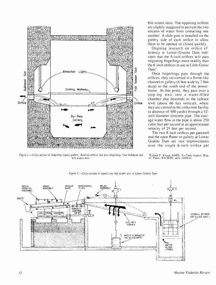
Fingerlings diverted from the turbine intakes to either the bul khead slot or the fish screen slot enter the bypass gallery by passing through one of two 8-inch illuminated orifices, about 6 feet below the water surface near the appropriate corners of the respective slots (Fig. 4). Orifices from the bulkhead slots empty into the gallery opposite those from the
/I
/' Orifice ~01~~~~
Attraction Lights
By- Pass Gallery
,~
Figure 4.-Cross seclion of hngerling bypass gallery, showing orifices Ihal pas; fingerlings from bulkhead and fi sh screen 51015 .
fish screen slots. The opposing ori fices are slightly staggered to prevent the two streams of water from contacting one another. A slide gate is installed on the gallery side of each orifice to allow them to be opened or closed quickly.
Ongoing research on orifice efficiency at Lower Granite Dam indicates that the 8-inch orifices will pass migrating fingerlings more readily than the 6-inch orifices in use at Little Goose Dam l
.
Once fingerlings pass through the orifices, they are carried in a flume-like channel or gallery (6 feet wide by 7 feet deep) to the south end of the powerhouse . At this point, they pass over a stop-log weir into a water-filled chamber that descends to the tailrace level (about 66 feet vertical), where they are carried to the collection facility (3 distance of 400 yards) through 3 42-inch diameter concrete pipe. The average water flow in the pipe is about 250 cubic feet per second at an approximate velocity of 25 feet per second.
The two 8-inch orifices per gatewell and the open flume or gallery at Lower Granite Dam are vast improvements over the single 6-inch orifice per
'Richard F . Krcma, NMFS, Tri-Cilies Airport, Bldg. 57, Pasco, WA 98301, pers . commun.
Figure 5 .-Cross seclion of upwell and fi sh grader unil at Lower Granile Dam.
J2
WATER SPRAYING ASSEMBlY
INCLINED SCREEN
WATER ELIMINATOR (42"SLUICE GATE J
UPWELL BY f'j\SS (72" SLUICE GATE J
Marine Fisheries Review

gatewell and closed pipe system in use aI Lillie Goose, Lower Monumental, and John Day Dams. Egress from gatewells is facilitated because fingerlings have to pass through only 9 inches of straight pipe into a well-lit flume instead of several feet of elbowed pipe into a dark transport pipe. In addition, much of the debris that continually plugs the 6-inch orifices readily passes through 8-inch orifice s. Further, the open flume permits ready access to any plugged orifice , whereas the closed systems require the use of scuba divers for debris removal.
Upwell and Fish Grader
As at Little Goose Dam, fish emerge from the upwell at the terminus of the transport pipe , are graded by size, and pass into the fi sh holding raceways. The design and operation of the upweJl and fish grading systems at both dams are basically similar. Some modifications of the facility at Lower Granite Dam were necessary to handle the eightfold increase in water volume. Other modifications were incorporated to improve the overall system. Basic features of the system are shown in Figure S. The following are the major differences from the system at Little Goose Dam:
I) A large inclined screen unit was installed in front of the perforated plate to offset the eightfold increase in water volume. The sc reen unit construction, including a sweeping mechanism to prevent plugging by debri s and algae, was patterned after an earlier screen described in detail by Kupka (1966). Manual or automatic regulation of water over the screen is provided by a 42-inch sluice gate beneath the screen, The excess water is passed back to the ri ver.
2) A 72-inch sluice gate in the upwell provides a means of returning the entire flow back to the river before it passes over the incl ined screen and fish grader. The entire flow is normally diverted directly to the river when fish are not migrating or not needed for collection.
3) The length of the fish grader has been increased to 20 feet, and a fourth water-filled hopper was installed under
Jull' 1977
the grader bars, This modification provides a finer degree of size grading, Adult salmon and trout that fail to fall through the grader bars enter a chute at the end of the grader and are discharged back to the river.
4) A chain-driven trash sweeping device installed directl y above the grader bars prevents the accumulation of water-borne debri s. (This is in addition to the standard traveling debri s collector between the grader bars and hoppers.) The new device consists of a bristle brush attached to an angle iron frame, suspended between two chains operating on guide bars and idler sprockets. Operation of this trash sweep can be controlled either manually (using a staner switch) or automatically (by means of an electric timer that regulates the operating interval). A limit switch ensures that the brush asse mbly will stop at the same point above the grader bars after each operation.
S) A water spraying assembly , consisting of evenly spaced yard-type sprinkler heads connected by pipe, is located above the grader bars. Thi s assembly provides a constant film of water on the grader bars , a llowing easier and faster movement of fish down them,
Fish Holding Area
The size and configuration of the fish holding raceways and the method of crowding are the same as previously described for Little Goose Dam, but some basic improvements have been incorporated . The raceways at Lower Granite Dam are above the level of the fish marking facility and the truck loading area, thereby providing complete movement of fish to these areas by gravity flow. Thi s design provides easier movement of fish and eliminates injuries which may occur with pumping, The last 2 feet of the downstream end of each raceway floor has been lowered I foot to provide a basin near the outlet pipe. This modification provides easier removal of the last few fi sh in each raceway by allowing complete drainage of the raceways-thereby congregating the remaining fish closer to the outlet pipe.
Fish Marking and Laboratory Facilities
The fish marking and laboratory complex is immediately down stream from the fish holding raceways (Fig. 6) , The complex consists of: I) a marking and sorting facility - wooden building with a concrete floor (1,024 square feet) and 2) laboratory , office, and related facilities-two mobile homes (720 square feet each), connected to each other and the marking facility by an enclosed porch .
During the sorting and marking operation, fish are transferred from the raceways by mean s of a 6-inch diameter fiber glass pipe running underground to a I ,OOO-gallon holding tank in the marking facility. From there , fish are placed into a sorting trough containing a temperature-controlled recirculating anesthetic bath and exam ined for previous marks and condition . Previously marked and poor quality fish not used for the transportation experiments are sent through a 3-inch diameter polyvinyl chloride (PVC) pipe, either directly to the transport truck or to an out side holding tank to recover from the anesthetic before being returned to the river. Unmarked fish to be used for the transportation experiments are sent through one of four 3-inch diameter PVC pipes to a marking station for adipose fin removal, freeze branding, and injection of a magnetic coded wire tag into the cartilage of the snout. The freeze brand and wire tag identify each experimental group, whereas the adipose fin clip simply indicates the presence of a wire tag in the fish 's snout. After completion of the marking process, the fish are sent through an electronic detector head that automatically rejects any untagged fi sh, thereby ensuring that only properly wire tagged fish are used in the transportation experiments. To inhibit fung al growth , properly tagged fish enter a 20-foot section of 3-inch diameter PVC pipe containing a recirculating, temperature-controlled solution of malachite green. At the end of thi s pipe, the fish pass over a screen device, that eliminates the malachite solution, and into a 6-inch diameter
13
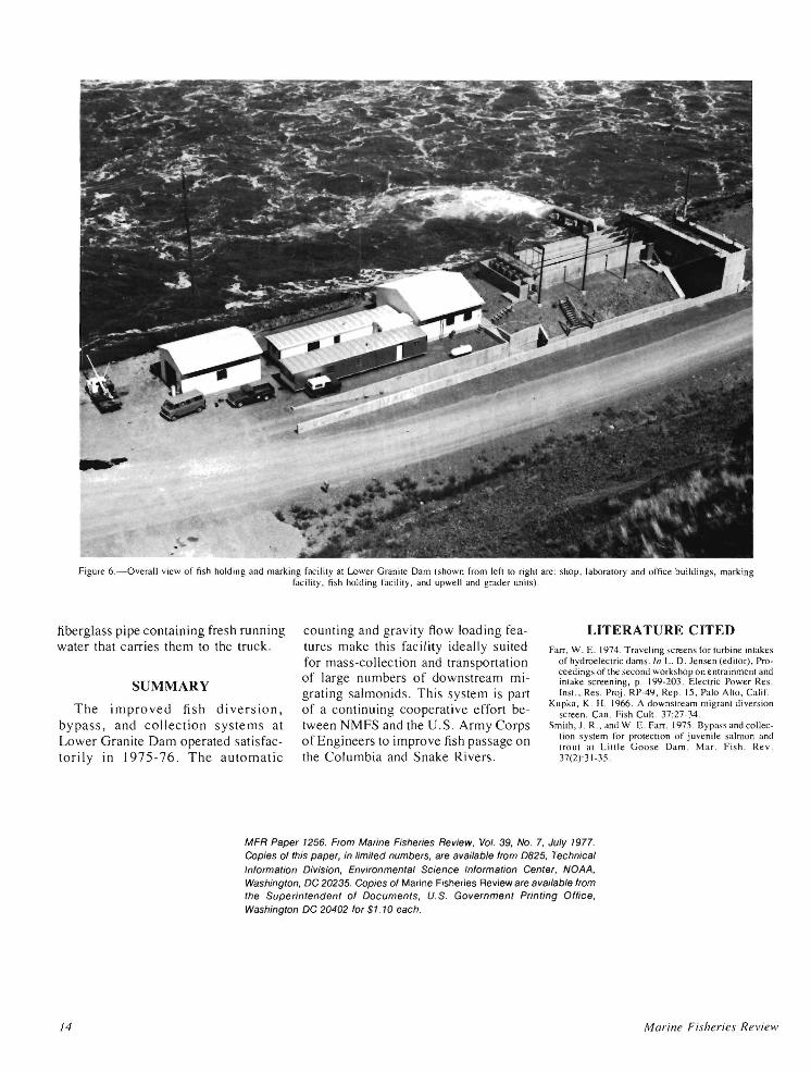
Figure 6.-0verall view of fi sh holding and marking facililY al Lower Granile Dam (shown from lefl 10 righl are: shop, laboralory and office buildings, marking facililY . fish holding facilil Y, and upwell and grader unils) .
fiberglass pipe containing fresh running water that carries them to the truck.
counting and gravity flow loading features make this facility ideally suited for mass-collection and transportation of large numbers of downstream migrating salmon ids . This system is part of a continuing cooperative effort between NMFS and the U.S. Army Corps of Engineers to improve fish passage on the Columbia and Snake Rivers.
LITERATURE CITED Farr. w. E. 1974. Traveling screens fonurbine inlakes
o f hydroeleclric dams. In L. D. Jensen (edilor), Proceedings of Ihe second works hop on enlrai nmenl and inlake scree ning, p. 199-203 . Eleclric Power Res. Insl .. Res. Proj . RP-49, Rep. 15. Palo Aho, Calif. SUMMARY
The improved fish diversion, bypass, and collection systems at Lower Granite Dam operated satisfactorily in 1975-76. The automatic
Kupka , K. H. 1966. A downslream migranl diversion screen. Can. Fish Cull. 37:27-34.
Smilh, J . R., and w. E. Farr. 1975 . Bypass and colleclion syslem for proleclion of juvenile salmon and IrOul al Lillie Goose Dam. Mar . Fish . Rev. 37(2):31-35.
/4
MFR Paper 1256. From Marine Fisheries Review, Vol. 39, NO. 7, July 1977. Copies of this paper, in limited numbers, are available from 0825, Technical Information Division, Environmental Science Information Center, NOAA, Washington, DC 20235. Copies of Marine Fisheries Review are available from the Superintendent of Documents, U.S. Government Printing Office, Washington DC 20402 for $1 .10 each.
Marine Fisheries Review
![Intake-Form.docx · Web viewPROJECT INTAKE FORM [PIF] Email the completed Project Intake Form to intake@vinecrestinvestments.com. as an editable MS Word attachment. Be sure to complete](https://static.fdocuments.net/doc/165x107/5e08269ea6d01c1aa7038e88/intake-formdocx-web-viewproject-intake-form-pif-email-the-completed-project.jpg)