Improve Your Automotive ECU Design with a Low-I Q Buck … · 2020-05-09 · Title: Improve Your...
4
DESIGN SOLUTIONS www.maximintegrated.com/design-solutions 1 AUTOMOTIVE Figure 2. CAN-Connected ECUs in a Car Powering the ECU The block diagram of a typical ECU is shown in Figure 3. The on-board buck converter powers the MCU, CAN, and I/Os while interfacing the battery via a pre-boost converter. A high and well-controlled PWM switching frequency, above the AM band, is required to reduce radio frequency interference while spread spectrum is necessary to meet electromagnetic interference (EMI) standards. With only 100µA of quiescent current at the ECU disposal, every microamp spared by the on- board buck converter is one more microamp that is usable for the module’s microcontroller, memory, or CAN. Finally, a high- efficiency buck converter will reduce the ECU heat generation, improving its reliability. Introduction High-end cars require close to a hundred electronic control units (ECUs), each taking power from the car battery with the intermediation of an on-board buck converter. As an example, an engine control unit is illustrated in Figure 1. Many ECUs must remain in standby mode even when the ignition key is off. Their standby currents add up, increasing the rate of discharge of the car battery. Accordingly, the quiescent current specification for these units is getting tougher to meet. The ECU buck converter must meet many other challenges inherent to the automotive environment. This article reviews the challenges of designing an ECU buck converter, from low quiescent current and low noise to high reliability. It introduces a new family of buck converters that addresses these challenges. Figure 1. Engine Control Unit ECUs in the Car ECUs are small computing modules that control most of the systems in a modern car. ECUs are connected via a controller area network (CAN) and control the car's engine, power windows, brakes, airbags, lights, entertainment system, steering functions, and more (Figure 2). To minimize the battery discharge, car manufacturers are specifying quiescent currents for ECUs as low as 100µA. Improve Your Automotive ECU Design with a Low-I Q Buck Converter
Transcript of Improve Your Automotive ECU Design with a Low-I Q Buck … · 2020-05-09 · Title: Improve Your...
DESIGN SOLUTIONS
www.maximintegrated.com/design-solutions 1
AUTOMOTIVE
Figure 2. CAN-Connected ECUs in a Car
Powering the ECU
The block diagram of a typical ECU is shown in Figure 3. The on-board buck converter powers the MCU, CAN, and I/Os while interfacing the battery via a pre-boost converter. A high and well-controlled PWM switching frequency, above the AM band, is required to reduce radio frequency interference while spread spectrum is necessary to meet electromagnetic interference (EMI) standards. With only 100µA of quiescent current at the ECU disposal, every microamp spared by the on-board buck converter is one more microamp that is usable for the module’s microcontroller, memory, or CAN. Finally, a high-efficiency buck converter will reduce the ECU heat generation, improving its reliability.
Introduction
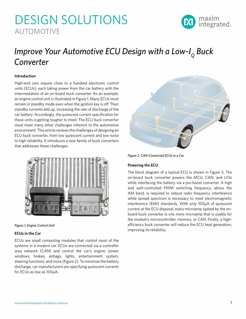
High-end cars require close to a hundred electronic control units (ECUs), each taking power from the car battery with the intermediation of an on-board buck converter. As an example, an engine control unit is illustrated in Figure 1. Many ECUs must remain in standby mode even when the ignition key is off. Their standby currents add up, increasing the rate of discharge of the car battery. Accordingly, the quiescent current specification for these units is getting tougher to meet. The ECU buck converter must meet many other challenges inherent to the automotive environment. This article reviews the challenges of designing an ECU buck converter, from low quiescent current and low noise to high reliability. It introduces a new family of buck converters that addresses these challenges.
Figure 1. Engine Control Unit
ECUs in the Car
ECUs are small computing modules that control most of the systems in a modern car. ECUs are connected via a controller area network (CAN) and control the car's engine, power windows, brakes, airbags, lights, entertainment system, steering functions, and more (Figure 2). To minimize the battery discharge, car manufacturers are specifying quiescent currents for ECUs as low as 100µA.
Improve Your Automotive ECU Design with a Low-IQ Buck Converter
www.maximintegrated.com/design-solutions 2
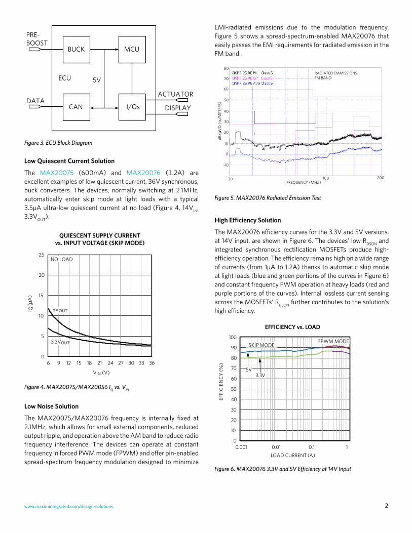
EMI-radiated emissions due to the modulation frequency. Figure 5 shows a spread-spectrum-enabled MAX20076 that easily passes the EMI requirements for radiated emission in the FM band.
RADIATED EMMISSIONSFM BAND
30 100 200FREQUENCY (MHZ)
80
70
dB (µ
VO
| ts
/MET
ERS)
60
50
40
30
20
10
0
-10
Figure 5. MAX20076 Radiated Emission Test
High Efficiency Solution
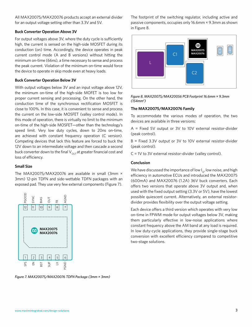
The MAX20076 efficiency curves for the 3.3V and 5V versions, at 14V input, are shown in Figure 6. The devices’ low RDSON and integrated synchronous rectification MOSFETs produce high-efficiency operation. The efficiency remains high on a wide range of currents (from 1µA to 1.2A) thanks to automatic skip mode at light loads (blue and green portions of the curves in Figure 6) and constant frequency PWM operation at heavy loads (red and purple portions of the curves). Internal lossless current sensing across the MOSFETs’ RDSON further contributes to the solution’s high efficiency.
0
10
20
30
40
50
60
70
80
90
100
0.001 0.01 0.1 1
EFFI
CIE
NC
Y (%
)
LOAD CURRENT (A)
5V3.3V
EFFICIENCY vs. LOAD
SKIP MODEFPWM MODE
Figure 6. MAX20076 3.3V and 5V Efficiency at 14V Input
MCU
I/Os
PRE-BOOST
DATA
ECU
BUCK
5V
CAN DISPLAY
ACTUATOR
Figure 3. ECU Block Diagram
Low Quiescent Current Solution
The MAX20075 (600mA) and MAX20076 (1.2A) are excellent examples of low quiescent current, 36V synchronous, buck converters. The devices, normally switching at 2.1MHz, automatically enter skip mode at light loads with a typical 3.5µA ultra-low quiescent current at no load (Figure 4, 14VIN, 3.3VOUT).
0
5
10
15
20
25
6 9 12 15 18 21 24 27 30 33 36
I Q(µ
A)
VIN (V)
NO LOAD
3.3VOUT
5VOUT
QUIESCENT SUPPLY CURRENTvs. INPUT VOLTAGE (SKIP MODE)
Figure 4. MAX20075/MAX20056 IQ vs. VIN
Low Noise Solution
The MAX20075/MAX20076 frequency is internally fixed at 2.1MHz, which allows for small external components, reduced output ripple, and operation above the AM band to reduce radio frequency interference. The devices can operate at constant frequency in forced PWM mode (FPWM) and offer pin-enabled spread-spectrum frequency modulation designed to minimize
www.maximintegrated.com/design-solutions 3
The footprint of the switching regulator, including active and passive components, occupies only 16.6mm × 9.3mm as shown in Figure 8.
L
C1
C2
C3 R1MAX20075MAX20076
Figure 8. MAX20075/MAX20056 PCB Footprint 16.6mm × 9.3mm (154mm2)
The MAX20075/MAX20076 Family
To accommodate the various modes of operation, the two devices are available in three versions:
A = Fixed 5V output or 3V to 10V external resistor-divider (peak control).
B = Fixed 3.3V output or 3V to 10V external resistor-divider (peak control).
C = 1V to 3V external resistor-divider (valley control).
Conclusion
We have discussed the importance of low IQ, low noise, and high efficiency in automotive ECUs and introduced the MAX20075 (600mA) and MAX20076 (1.2A) 36V buck converters. Each offers two versions that operate above 3V output and, when used with the fixed output setting (3.3V or 5V), have the lowest possible quiescent current. Alternatively, an external resistor-divider provides flexibility over the output voltage setting.
Each device offers a third version which operates with very low on-time in FPWM mode for output voltages below 3V, making them particularly effective in low-noise applications where constant frequency above the AM band at any load is required. In low duty-cycle applications, they provide single-stage buck conversion with excellent efficiency compared to competitive two-stage solutions.
All MAX20075/MAX20076 products accept an external divider for an output voltage setting other than 3.3V and 5V.
Buck Converter Operation Above 3V
For output voltages above 3V, where the duty cycle is sufficiently high, the current is sensed on the high-side MOSFET during its conduction (on) time. Accordingly, the device operates in peak current control mode (A and B versions) without hitting the minimum on-time (66ns), a time necessary to sense and process the peak current. Violation of the minimum on-time would force the device to operate in skip mode even at heavy loads.
Buck Converter Operation Below 3V
With output voltages below 3V and an input voltage above 12V, the minimum on-time of the high-side MOFET is too low for proper current sensing and processing. On the other hand, the conduction time of the synchronous rectification MOSFET is close to 100%. In this case, it is convenient to sense and process the current on the low-side MOSFET (valley control mode). In this mode of operation, there is virtually no limit to the minimum on-time of the high-side MOSFET—other than the technology’s speed limit. Very low duty cycles, down to 20ns on-time, are achieved with constant frequency operation (C version). Competing devices that lack this feature are forced to buck the 12V down to an intermediate voltage and then cascade a second buck converter down to the final VOUT at greater financial cost and loss of efficiency.
Small Size
The MAX20075/MAX20076 are available in small (3mm × 3mm) 12-pin TDFN and side-wettable TDFN packages with an exposed pad. They use very few external components (Figure 7).
+
PGO
OD
12
AG
ND
7
SYN
C
11
BIA
S
10
OU
T
9
FB
8
1 62 3 4 5
SPS
PGN
DEN BST
SUP LX
MAX20075MAX20076
Figure 7. MAX20075/MAX20076 TDFN Package (3mm × 3mm)
Maxim Integrated and the Maxim logo are registered trademarks of Maxim Integrated Corporation. All other trademarks are the property of their respective owners.
Maxim Integrated160 Rio RoblesSan Jose, CA 95134 USA408-601-1000
maximintegrated.com/design-solutions4
Glossary
ECU: Electronic control unit
EMI: Electromagnetic interference
CAN: Controller area network
V+: Denotes automotive grade part
Learn more:
MAX20075 36V, 600mA, Mini Buck Converter with 3.5μA IQMAX20076 36V, 1.2A Mini Buck Converter with 3.5μA IQ
Design Solutions No. 54
Find More Design Solutions
Rev 0; September 2017
Visit the Maxim Support Center