Improve Quality, Reduce Costs, and Increase Efficiency ... · PDF fileImprove Quality, Reduce...
11
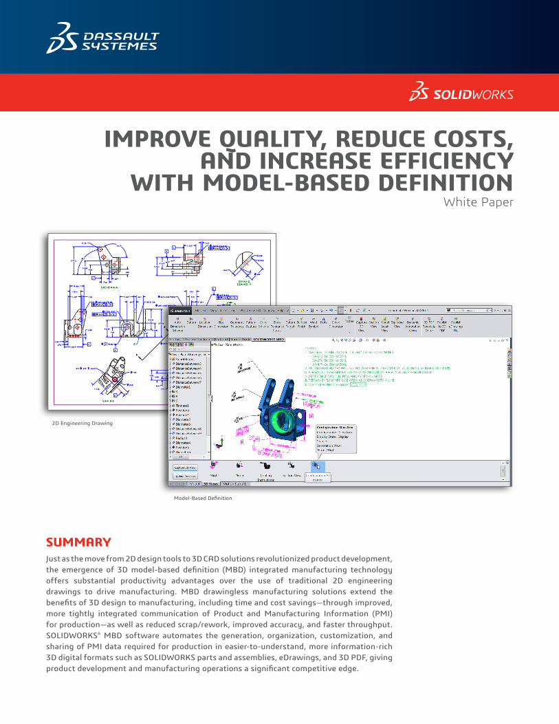
IMPROVE QUALITY, REDUCE COSTS, AND INCREASE EFFICIENCY WITH MODEL-BASED DEFINITION White Paper SUMMARY Just as the move from 2D design tools to 3D CAD solutions revolutionized product development, the emergence of 3D model-based definition (MBD) integrated manufacturing technology offers substantial productivity advantages over the use of traditional 2D engineering drawings to drive manufacturing. MBD drawingless manufacturing solutions extend the benefits of 3D design to manufacturing, including time and cost savings—through improved, more tightly integrated communication of Product and Manufacturing Information (PMI) for production—as well as reduced scrap/rework, improved accuracy, and faster throughput. SOLIDWORKS ® MBD software automates the generation, organization, customization, and sharing of PMI data required for production in easier-to-understand, more information-rich 3D digital formats such as SOLIDWORKS parts and assemblies, eDrawings, and 3D PDF, giving product development and manufacturing operations a significant competitive edge. 2D Engineering Drawing Model-Based Definition
Transcript of Improve Quality, Reduce Costs, and Increase Efficiency ... · PDF fileImprove Quality, Reduce...
IMPROVE QUALITY, REDUCE COSTS, AND INCREASE EFFICIENCY
WITH MODEL-BASED DEFINITION White Paper
SUMMARYJust as the move from 2D design tools to 3D CAD solutions revolutionized product development, the emergence of 3D model-based definition (MBD) integrated manufacturing technology offers substantial productivity advantages over the use of traditional 2D engineering drawings to drive manufacturing. MBD drawingless manufacturing solutions extend the benefits of 3D design to manufacturing, including time and cost savings—through improved, more tightly integrated communication of Product and Manufacturing Information (PMI) for production—as well as reduced scrap/rework, improved accuracy, and faster throughput. SOLIDWORKS® MBD software automates the generation, organization, customization, and sharing of PMI data required for production in easier-to-understand, more information-rich 3D digital formats such as SOLIDWORKS parts and assemblies, eDrawings, and 3D PDF, giving product development and manufacturing operations a significant competitive edge.
2D Engineering Drawing
Model-Based Definition
Improve Quality, Reduce Costs, and Increase Efficiency with Model-Based Definition 1
MODEL-BASED DEFINITION: A MORE EFFICIENT DRAWINGLESS APPROACH TO MANUFACTURINGMost of today’s successful manufacturers have realized significant productivity gains by migrating from 2D tools to 3D design systems for product development. The impact of 3D on design is indisputable, enabling companies around the world to accelerate time-to-market, improve design for manufacturability, eliminate unnecessary costs, and stimulate greater innovation. Even though product developers and design engineers have embraced 3D design—realizing a range of well-documented benefits—the output of 3D CAD systems when a design is released to internal manufacturing departments or external production partners continues in large part to be 2D paper engineering drawings.
Despite the fact that 3D solid models are easier to understand and visualize—not requiring the extrapolation of 2D line drawings into 3D shapes—and contain all of the required Product and Manufacturing Information (PMI) within their file data structures, 2D drawings have remained the primary means for conveying all of the information required for manufacturing. While 3D modeling has accelerated product development, the wide adoption and continued use of 2D drawings to support production has limited the potential impact of 3D on the manufacturing side of the equation.
Why do most manufacturing operations continue to use paper 2D drawings? Familiarity, tradition, and resistance to change have certainly played a role, as has the absence of complete, integrated 3D drawingless manufacturing solutions. Why should manufacturers be concerned about their reliance on 2D drawings to support production? Don’t drawings continue to effectively communicate all of the required information to manufacture products and components—including datum references and coordinate systems, dimensions and tolerances, bills of materials (BOMs) and notes, surface finishes and welding techniques, and a range of other types of information?
The answer is that 3D can revolutionize manufacturing in much the same way as it has advanced product design. Ignoring this potential for 3D in manufacturing is like using a smartphone just for telephone calls or using the web just to send and receive email messages. MBD will help you unleash the manufacturing potential of 3D by more efficiently, accurately, and cost-effectively integrating PMI into 3D models to help communicate the design intention traditionally through 2D drawings.
The convergence of 3D design tools and digital viewing devices—including increasingly affordable monitors, laptops, tablets, and smartphones—combined with the revision/access controls of product data management systems, creates the real opportunity to leverage 3D models in more efficient ways to support manufacturing through model-based definition (MBD). The four basic stages of the model-based enterprise (MBE) are:
Improve Quality, Reduce Costs, and Increase Efficiency with Model-Based Definition 2
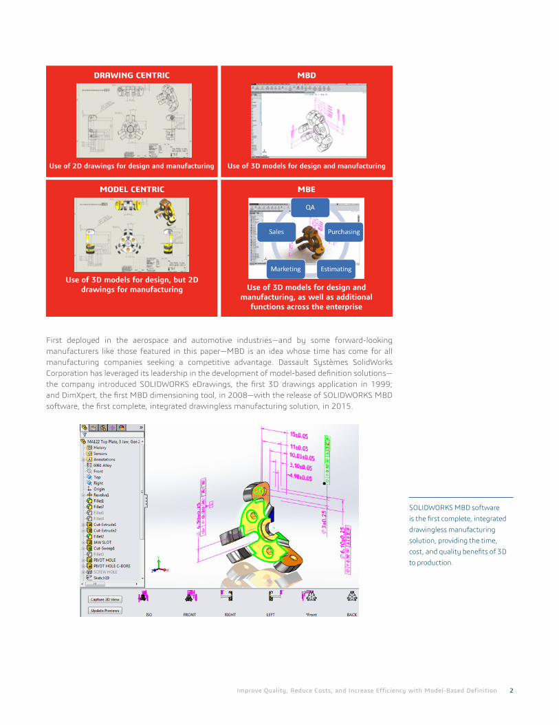
First deployed in the aerospace and automotive industries—and by some forward-looking manufacturers like those featured in this paper—MBD is an idea whose time has come for all manufacturing companies seeking a competitive advantage. Dassault Systèmes SolidWorks Corporation has leveraged its leadership in the development of model-based definition solutions—the company introduced SOLIDWORKS eDrawings, the first 3D drawings application in 1999; and DimXpert, the first MBD dimensioning tool, in 2008—with the release of SOLIDWORKS MBD software, the first complete, integrated drawingless manufacturing solution, in 2015.
SOLIDWORKS MBD software is the first complete, integrated drawingless manufacturing solution, providing the time, cost, and quality benefits of 3D to production.
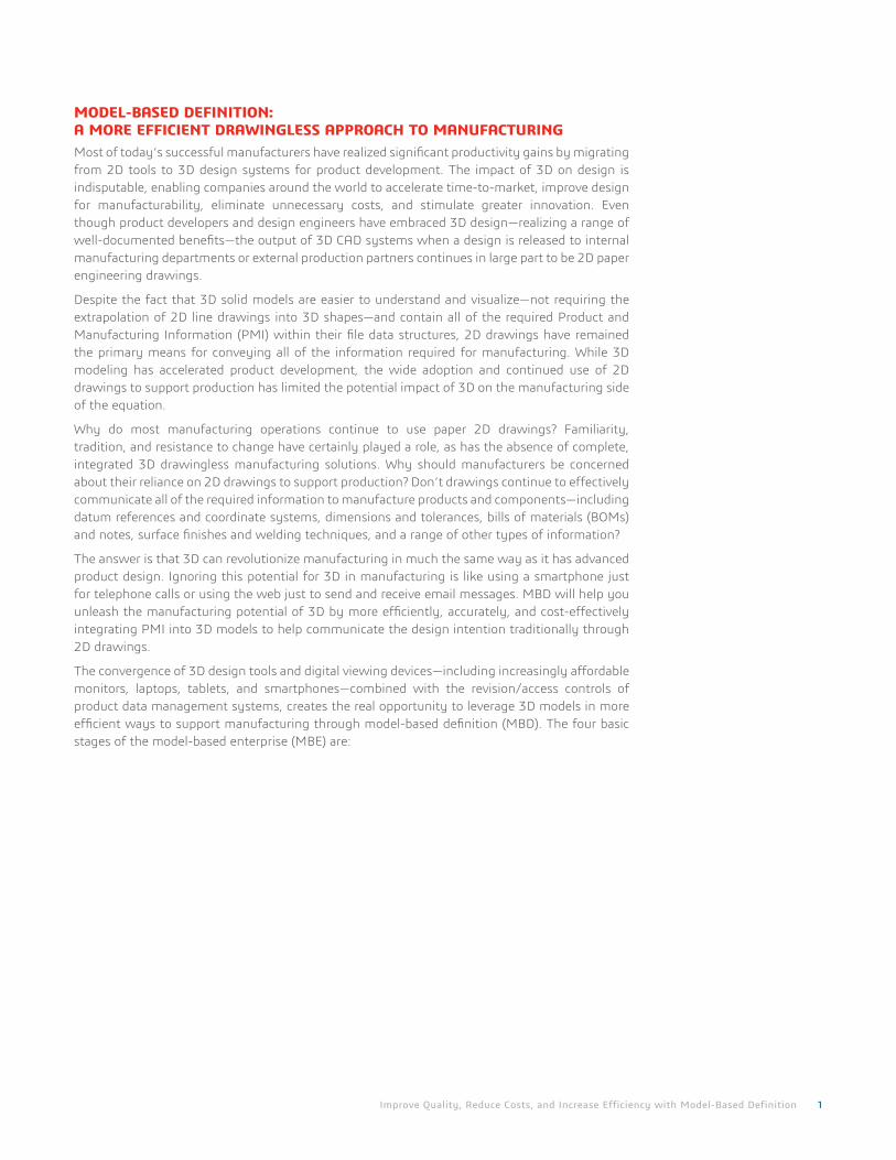
DRAWING CENTRIC
Use of 2D drawings for design and manufacturing
MBD
Use of 3D models for design and manufacturing
MODEL CENTRIC
Use of 3D models for design, but 2D drawings for manufacturing
MBE
Use of 3D models for design and manufacturing, as well as additional
functions across the enterprise
Improve Quality, Reduce Costs, and Increase Efficiency with Model-Based Definition 3
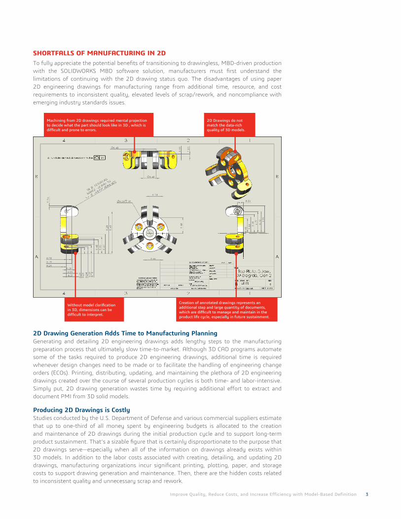
SHORTFALLS OF MANUFACTURING IN 2DTo fully appreciate the potential benefits of transitioning to drawingless, MBD-driven production with the SOLIDWORKS MBD software solution, manufacturers must first understand the limitations of continuing with the 2D drawing status quo. The disadvantages of using paper 2D engineering drawings for manufacturing range from additional time, resource, and cost requirements to inconsistent quality, elevated levels of scrap/rework, and noncompliance with emerging industry standards issues.
2D Drawing Generation Adds Time to Manufacturing PlanningGenerating and detailing 2D engineering drawings adds lengthy steps to the manufacturing preparation process that ultimately slow time-to-market. Although 3D CAD programs automate some of the tasks required to produce 2D engineering drawings, additional time is required whenever design changes need to be made or to facilitate the handling of engineering change orders (ECOs). Printing, distributing, updating, and maintaining the plethora of 2D engineering drawings created over the course of several production cycles is both time- and labor-intensive. Simply put, 2D drawing generation wastes time by requiring additional effort to extract and document PMI from 3D solid models.
Producing 2D Drawings is CostlyStudies conducted by the U.S. Department of Defense and various commercial suppliers estimate that up to one-third of all money spent by engineering budgets is allocated to the creation and maintenance of 2D drawings during the initial production cycle and to support long-term product sustainment. That’s a sizable figure that is certainly disproportionate to the purpose that 2D drawings serve—especially when all of the information on drawings already exists within 3D models. In addition to the labor costs associated with creating, detailing, and updating 2D drawings, manufacturing organizations incur significant printing, plotting, paper, and storage costs to support drawing generation and maintenance. Then, there are the hidden costs related to inconsistent quality and unnecessary scrap and rework.
Machining from 2D drawings required mental projection to decide what the part should look like in 3D , which is difficult and prone to errors.
Without model clarification in 3D, dimensions can be difficult to interpret.
2D Drawings do not match the data-rich quality of 3D models.
Creation of annotated drawings represents an additional step and large quantity of documents, which are difficult to manage and maintain in the product life cycle, especially in future sustainment.
Improve Quality, Reduce Costs, and Increase Efficiency with Model-Based Definition 4
2D Creates the Potential for Quality IssuesNot only are 2D drawings often difficult to understand and easy to misinterpret, they don’t always match their associated 3D designs. Studies show that this disconnect occurs up to 60 percent of the time, resulting in massive downstream production failures, inconsistent quality, and unnecessary waste. While this disconnect rate varies from company to company, 2D drawings require manufacturers to actually retreat from the intuitive nature of 3D—projecting from 3D to fully detail 2D drawings—then reconstructing 2D representations into 3D for production. This process exposes manufacturers to quality issues by creating opportunities for misinterpretation and errors, leading to product failures, the need to engage in retrofits during manufacturing to address problems, or higher volumes of scrap and waste.
Emerging Industry Standards Require 3DAlthough manufacturers have utilized 2D engineering drawings to support production for many years, some large organizational customers are beginning to demand production data in 3D as a basic requirement for doing business. For example, the U.S. Department of Defense acknowledged the substantial benefits of MBD 3D-driven manufacturing by publishing Revision A to Military Standard-31000 in 2013, fully defining the requirements for model-based deliverables for its entire supply chain, a requirement that it expects to save hundreds of millions of dollars annually when fully adopted. Similarly, some large commercial concerns have set targets, as well as cycle time objectives, related to MBD. These trends are generating strong ripple effects throughout the supply chain, at machine shops, and for small manufacturing businesses.
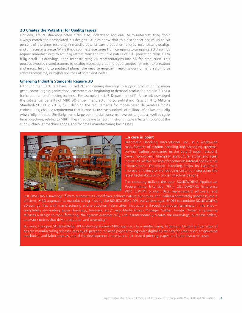
…a case in pointAutomatic Handling International, Inc., is a worldwide manufacturer of custom handling and packaging systems, serving leading companies in the pulp & paper, tissue & towel, nonwovens, fiberglass, agriculture, stone, and steel industries. With a mission of continuous internal and external improvement, Automatic Handling helps its customers improve efficiency while reducing costs by integrating the latest technology with proven machine designs.
The company utilized the open SOLIDWORKS Application Programming Interface (API), SOLIDWORKS Enterprise PDM (EPDM) product data management software, and
SOLIDWORKS eDrawings® files to automate its workflows, achieve natural synergies, and realize a completely paperless, more efficient, MBD approach to manufacturing. “Using the SOLIDWORKS API, we’ve leveraged EPDM to combine SOLIDWORKS eDrawings files with manufacturing and production information instructions through computer terminals in the shop—completely eliminating paper drawings, travelers, etc.,” says Media Group Manager Nathan Pienta. “When engineering releases a design to manufacturing, the system automatically and instantaneously creates the eDrawings, purchase orders, and work orders that drive production and assembly.”
By using the open SOLIDWORKS API to develop its own MBD approach to manufacturing, Automatic Handling International has cut manufacturing release times by 80 percent; replaced paper drawings with digital 3D models for production; empowered machinists and fabricators as part of the development process; and eliminated printing, paper, and administrative costs.
Improve Quality, Reduce Costs, and Increase Efficiency with Model-Based Definition 5
ADVANTAGES OF DRAWINGLESS MANUFACTURINGWith drawingless production, manufacturers can realize many of the same benefits that they’ve enjoyed from developing products in 3D in their manufacturing operations. Incorporating a MBD manufacturing approach is a smoother transition—with faster return on investment (ROI)—than migrating from 2D to 3D for design. That’s because the information provided in 3D digital formats is the same as the PMI data included on 2D engineering drawings. 3D is simply clearer and easier to understand, and it’s more efficient to generate and utilize MBD information for production. Even further, with the help of digital devices, instead of shuffling through stacks of paper prints, production personnel can access PMI electronically and actually see the part to be manufactured, or the product to be assembled, in 3D.
Bringing Products to Market FasterBecause MBD eliminates the need to generate 2D engineering drawings for production and reduces the time and effort required to repeatedly clarify confusing 2D drawings and to provide detailed PMI data by calling out only critical dimensions and querying models for the rest, it can help manufacturers shorten production cycles and accelerate time-to-market. MBD production also accelerates the handling of engineering change orders (ECOs) when design changes are made after a part or product is released to manufacturing, because the change to the model will automatically update all associated PMI in one master model rather across multiple disconnected documents. Instead of having to manually detail updates to various drawings views, MBD automates the process, saving valuable time and keeping production online.
Reducing Production CostsDrawingless MBD production enables reductions in manufacturing costs. Some of the cost savings are obvious, such as labor cost reductions associated with 2D detailing and the expenses related to printing and maintaining drawings, including printing, plotting, and paper expenses if digital devices are fully implemented. Other savings come in the form of improved quality—resulting in less scrap/rework and fewer warranty claims/returns—or decreased procurement costs for purchased parts because suppliers can lower their cost by reusing 3D PMI, rather than rebuilding 3D models per 2D drawings. MBD also lowers the overall sustainment costs of a product over its entire lifecycle by providing an easily accessible “digital thread” of manufacturing information for years to come.
Improving Quality, Accelerating Engineering Change OrdersMBD addresses the limitations of 2D drawings that can lead to inconsistent quality. By providing fast access to detailed 3D views containing all of the necessary PMI for manufacturing parts or assembling them into a product, MBD production minimizes the misinterpretations and surprises that can result in errors, defects, and field failures. Because handling an ECO becomes an easy, streamlined process with MBD—rather than the deadline- and budget-busting nightmare associated with executing ECOs in 2D— manufacturers have greater incentive to make quality improvements and changes immediately, leading to more consistently high levels of quality.
Complying with New StandardsJust as manufacturers have required 2D engineering drawings for production, new standards and targets that require PMI in MBD formats have begun to emerge. Commercial companies, governmental agencies, and international organizations are driving this transition to Model-Based Definition. For example, The U.S. Department of Defense published Revision A to Military Standard-31000 in 2013 to fully define the requirements for model-based deliverables for its entire supply chain. Other applicable standards include ASME Y14.41, ISO 16792, DIN ISO 16792, and GB/T 24734.
Improve Quality, Reduce Costs, and Increase Efficiency with Model-Based Definition 6
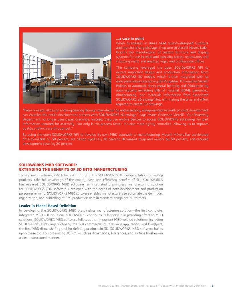
…a case in pointWhen businesses in Brazil need custom-designed furniture and merchandising displays, they turn to Viecelli Móveis Ltda., Brazil’s top manufacturer of custom furniture and display systems for use in retail and specialty stores; restaurants and shopping malls; and medical, legal, and professional offices.
The company leveraged the open SOLIDWORKS API to extract important design and production information from SOLIDWORKS 3D models, which it then integrated with its enterprise resource planning (ERP) system. This enables Viecelli Móveis to automate sheet metal bending and fabrication by automatically extracting bills of material (BOM), geometric, dimensioning, and materials information from associated SOLIDWORKS eDrawings files, eliminating the time and effort required to create 2D drawings.
“From conceptual design and engineering through manufacturing and assembly, everyone involved with product development can visualize the entire development process with SOLIDWORKS eDrawings,” says owner Anderson Viecelli. “Our Assembly Department no longer uses paper drawings. Instead, they use mobile devices to access SOLIDWORKS eDrawings for part information required for assembly. Not only is the process faster, it’s also more tightly controlled, allowing us to improve quality and increase throughput.”
By using the open SOLIDWORKS API to develop its own MBD approach to manufacturing, Viecelli Móveis has accelerated time-to-market by 50 percent, cut design cycles by 30 percent, decreased scrap and rework by 50 percent, and reduced development costs by 20 percent.
SOLIDWORKS MBD SOFTWARE: EXTENDING THE BENEFITS OF 3D INTO MANUFACTURINGTo help manufacturers, which benefit from using the SOLIDWORKS 3D design solution to develop products, take full advantage of the quality, cost, and efficiency benefits of 3D, SOLIDWORKS has released SOLIDWORKS MBD software, an integrated drawingless manufacturing solution for SOLIDWORKS CAD software. Developed with the needs of both development and production personnel in mind, SOLIDWORKS MBD software enables manufacturers to automate the definition, organization, and publishing of PMI production data in standard-compliant 3D formats.
Leader in Model-Based DefinitionIn developing the SOLIDWORKS MBD drawingless manufacturing solution—the first complete, integrated MBD CAD solution—SOLIDWORKS continues its leadership in providing effective MBD solutions. SOLIDWORKS MBD software follows other important MBD-related solutions, including SOLIDWORKS eDrawings software, the first commercial 3D drawings application; and DimXpert, the first MBD dimensioning tool for defining products in 3D. SOLIDWORKS MBD software builds upon these tools by organizing 3D PMI—such as dimensions, tolerances, and surface finishes—in a clean, structured manner.
Improve Quality, Reduce Costs, and Increase Efficiency with Model-Based Definition 7
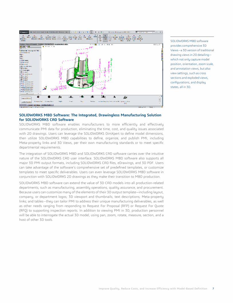
SOLIDWORKS MBD Software: The Integrated, Drawingless Manufacturing Solution for SOLIDWORKS CAD SoftwareSOLIDWORKS MBD software enables manufacturers to more efficiently and effectively communicate PMI data for production, eliminating the time, cost, and quality issues associated with 2D drawings. Users can leverage the SOLIDWORKS DimXpert to define model dimensions, then utilize SOLIDWORKS MBD capabilities to define, organize, and publish PMI, including Meta-property links and 3D Views, per their own manufacturing standards or to meet specific departmental requirements.
The integration of SOLIDWORKS MBD and SOLIDWORKS CAD software carries over the intuitive nature of the SOLIDWORKS CAD user interface. SOLIDWORKS MBD software also supports all major 3D PMI output formats, including SOLIDWORKS CAD files, eDrawings, and 3D PDF. Users can take advantage of the software’s comprehensive set of predefined templates, or customize templates to meet specific deliverables. Users can even leverage SOLIDWORKS MBD software in conjunction with SOLIDWORKS 2D drawings as they make their transition to MBD production.
SOLIDWORKS MBD software can extend the value of 3D CAD models into all production-related departments, such as manufacturing, assembly operations, quality assurance, and procurement. Because users can customize many of the elements of their 3D output template—including layout, company, or department logos; 3D viewport and thumbnails; text descriptions; Meta-property links; and tables—they can tailor PMI to address their unique manufacturing deliverables, as well as other needs ranging from responding to Request For Proposal (RFP) or Request For Quote (RFQ) to supporting inspection reports. In addition to viewing PMI in 3D, production personnel will be able to interrogate the actual 3D model, using pan, zoom, rotate, measure, section, and a host of other 3D tools.
SOLIDWORKS MBD software provides comprehensive 3D Views—a 3D version of traditional drawing views in 2D detailing—which not only capture model position, orientation, zoom scale, and annotation views, but also view settings, such as cross sections and exploded views, configurations, and display states, all in 3D.
Improve Quality, Reduce Costs, and Increase Efficiency with Model-Based Definition 8
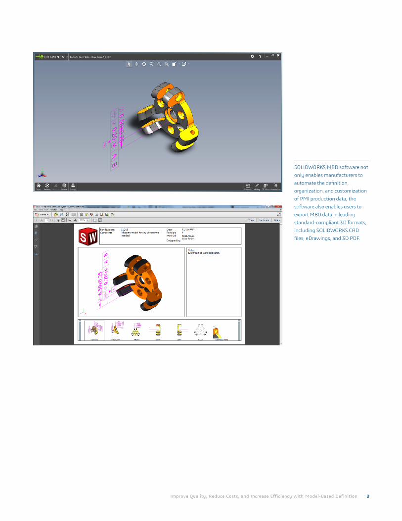
SOLIDWORKS MBD software not only enables manufacturers to automate the definition, organization, and customization of PMI production data, the software also enables users to export MBD data in leading standard-compliant 3D formats, including SOLIDWORKS CAD files, eDrawings, and 3D PDF.
Improve Quality, Reduce Costs, and Increase Efficiency with Model-Based Definition 9
Benefits of SOLIDWORKS MBD Software• Reduces procurement cost and achieves quicker supplier response through model-based
communication.
• Cuts tooling and fabrication costs.
• Removes the time required to clean up 2D drawings.
• Reduces time required to create and maintain manufacturing documentation.
• Reduces the number of annotations and dimensions.
• Reduces engineering changes.
• Streamlines the ECO process.
• Reduces the number of files for sign-off.
• Reduces errors.
• Removes model-to-drawing discrepancy.
• Manipulates the 3D model directly for clarity.
• Cuts scrap and rework.
• Complies with emerging industry standards
• Fits into a company’s and/or supply chain’s existing processes seamlessly.
• Exports widely accepted industry formats, including 3D PDF, eDrawings, and SOLIDWORKS files.
• SOLIDWORKS reads DWG files into sketches or 2D Drawings so that users can build 3D models based on legacy data.
• Saves time wasted on re-modeling parts based on 2D Drawings.
• Shares and archives intelligent and intuitive 3D data directly to models, PMI, views, and Meta properties so that users and their suppliers don’t have to waste time in re-modeling parts based on traditional 2D drawings. Upgrades existing products to new models much faster and designs tooling and fixtures more easily based on 3D data.
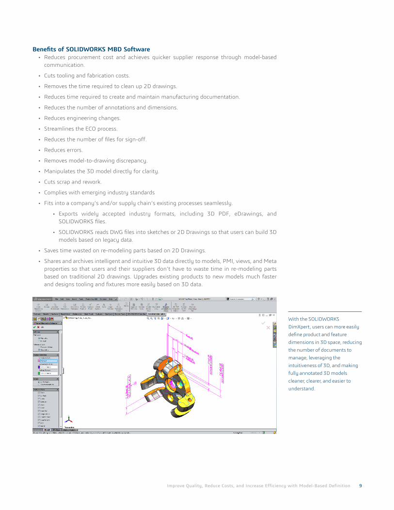
With the SOLIDWORKS DimXpert, users can more easily define product and feature dimensions in 3D space, reducing the number of documents to manage, leveraging the intuitiveness of 3D, and making fully annotated 3D models cleaner, clearer, and easier to understand.
Our 3DEXPERIENCE Platform powers our brand applications, serving 12 industries, and provides a rich portfolio of industry solution experiences. Dassault Systèmes, the 3DEXPERIENCE Company, provides business and people with virtual universes to imagine sustainable innovations. Its world-leading solutions transform the way products are designed, produced, and supported. Dassault Systèmes’ collaborative solutions foster social innovation, expanding possibilities for the virtual world to improve the real world. The group brings value to over 170,000 customers of all sizes in all industries in more than 140 countries. For more information, visit www.3ds.com.
©20
14 D
assa
ult S
ystè
mes
. All
righ
ts re
serv
ed. 3
DEX
PER
IEN
CE, t
he C
ompa
ss ic
on a
nd th
e 3D
S lo
go, C
ATI
A, S
OLI
DW
OR
KS, E
NO
VIA
, DEL
MIA
, SIM
ULI
A, G
EOVI
A, E
XALE
AD
, 3D
VIA
, BIO
VIA
, NET
VIB
ES, a
nd 3
DXC
ITE
are
com
mer
cial
trad
emar
ks
or re
gist
ered
trad
emar
ks o
f Das
saul
t Sys
tèm
es o
r its
sub
sidi
arie
s in
the
U.S
. and
/or o
ther
cou
ntri
es. A
ll ot
her t
rade
mar
ks a
re o
wne
d by
thei
r res
pect
ive
owne
rs. U
se o
f any
Das
saul
t Sys
tèm
es o
r its
sub
sidi
arie
s tr
adem
arks
is s
ubje
ct to
thei
r exp
ress
wri
tten
app
rova
l.
Corporate HeadquartersDassault Systèmes 10, rue Marcel Dassault CS 40501 78946 Vélizy-Villacoublay Cedex France
AmericasDassault Systèmes SolidWorks Corporation 175 Wyman Street Waltham, MA 02451 USA Phone: 1 800 693 9000 Outside the US: +1 781 810 5011 Email: [email protected]
Asia-PacificDassault Systèmes K.K.ThnkPark Tower2-1-1 Osaki, Shinagawa-ku,Tokyo 141-6020Japan
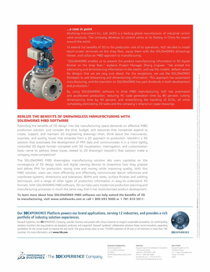
…a case in pointWuzhong Instrument Co., Ltd. (WZI) is a leading global manufacturer of industrial control valve products. The company develops its control valves at its factory in China for export around the world.
To extend the benefits of 3D to the production side of its operations, WZI decided to install touch-screen terminals on the shop floor, equip them with the SOLIDWORKS eDrawings Viewer, and utilize an MBD approach to manufacturing.
“SOLIDWORKS enables us to present the product manufacturing information in 3D digital format on the shop floor,” explains Project Manager Zhang Jingwen. “We embed the tolerancing and dimensioning information in the sketch, and use the models’ default values for designs that we are very sure about. For the exceptions, we use the SOLIDWORKS DimXpert to add tolerancing and dimensioning information. This approach has automated manufacturing, and the transition to SOLIDWORKS has paid dividends in both development and production.”
By using SOLIDWORKS software to drive MBD manufacturing, WZI has automated and accelerated production, reducing NC code generation time by 80 percent, cutting dimensioning time by 40 percent, and streamlining the handling of ECOs, all while completely eliminating 2D tasks and the company’s reliance on paper drawings.
REALIZE THE BENEFITS OF DRAWINGLESS MANUFACTURING WITH SOLIDWORKS MBD SOFTWAREExtending the benefits of 3D design into the manufacturing space demands an effective MBD production solution. Just consider the time, budget, and resources that companies expend to create, support, and maintain 2D engineering drawings—then, think about the inaccuracies, surprises, and quality issues that emanate from a 2D approach to production. Wouldn’t a 3D solution that automates the development of PMI data and communicates it in a more tightly controlled 3D digital format—complete with 3D visualization, interrogation, and customization tools—serve to address these issues related to 2D drawings? Wouldn’t that solution make a company more competitive?
The SOLIDWORKS MBD drawingless manufacturing solution lets users capitalize on the convergence of 3D design tools and digital viewing devices to streamline how they prepare and deliver PMI for production, saving time and money while improving quality. With this MBD solution, users can more efficiently and effectively communicate datum references and coordinate systems, dimensions and tolerances, BOMs and notes, surface finishes and welding techniques, and a range of other types of production information in easy-to-understand 3D formats. With SOLIDWORKS MBD software, 3D can help users modernize production planning and manufacturing processes in much the same way that it has revolutionized product development.
To learn more about how SOLIDWORKS MBD software can help extend the benefits of 3D to manufacturing, visit www.solidworks.com or call 1 800 693 9000 or 1 781 810 5011.