
Impression Evidence: Footwear and Tool Marks Cases...
53
1 Impression Evidence: Footwear and Tool Marks Cases from the Crime Scene to the Courtroom By Nicholas Petraco, MS, D-ABC Nicholas D. K. Petraco, PhD In: Forensic Science Handbook, Volume II; CRC Press, Boca Raton, FL, 2016
Transcript of Impression Evidence: Footwear and Tool Marks Cases...

1
Impression Evidence: Footwear and Tool Marks Cases from the Crime Scene to the Courtroom
By
Nicholas Petraco, MS, D-ABC Nicholas D. K. Petraco, PhD
In: Forensic Science Handbook, Volume II; CRC Press, Boca Raton, FL, 2016

2
Marks in the form of imprints deposited onto surfaces resulting from the interaction of objects with surfaces were often used as proof in court to confirm that a known object was used to make a questioned mark or impression found at the scene of a crime. Objects such as footwear, tires and tools typically leave 2 or 3 dimensional images of their profiles on or within the surfaces with which they come into contact as shown in Figures 1-3.
Figure 1 – Two-dimensional residual blood footwear print from a homicide scene. The chain of events leading to testimony in court normally starts with the discovery, documentation and collection of a questioned mark or imprint at a crime scene by a crime scene technician who packages and transports the evidence to an accredited forensic laboratory. Next, the collected evidence is assigned to the appropriate certified forensic expert. The expert should be informed by the investigator of all the details pertaining to the crime. The forensic expert will first assess any questioned impression he or she receives during the investigations. In the case of footwear evidence, if required, the footwear experts have a great number of will accepted enhancement techniques at their disposal to further develop the questioned print(s). Next, the footwear expert most obtain a suspect’s known shoes in order make an assessment as to the possible origin of the questioned print(s). After first photographing the suspect’s shoes, the expert prepares known test impressions of the suspect’s shoes by preparing the appropriate 2 or 3-dimensional test print. Finally, the known and questioned impressions were compared to assess whether the questioned prints found at the crime scene could have been made by the suspect’s known shoes. This is normally achieved by examining and comparing the class characteristics, subclass characteristics, wear patterns and accidental marks exhibited by the questioned and known prints.

3
Figure 2 – Three-dimensional questioned footwear impression in sand from homicide scene. In the case of tool mark evidence the forensic expert follows the same general rational in comparing and assessing whether a questioned tool mark found at a crime scene was made by a known tool obtained from a suspect.
Figure 3 – Questioned tool marks made on a locks strike plate. Unfortunately, most police investigator personnel, even in the 21st century; do not possess the training or the knowledge, skills and ability to successfully document, recover, process, examine, compare and bring to the judicial system these forms of impression evidence. This chapter is presented to help remedy this situation.

4
Most scene of crime often appears chaotic, as seen in Figure 4. Understanding the nature and complexity of impression evidence and how it relates to the rest of the crime scene can only be achieved with hard work, practice and experience. The visual nature of this form of physical evidence whether a distinct foot print, or obvious tool mark often fool even the most seasoned investigator(s) into thinking they can interpret its significance with a cursory examination. This approach often leads to misinterpretation of the evidence and even worse, wrongful arrest and/or convictions. Consequently, only highly trained, certified criminalists or crime scene specialists following discipline wide accepted evidence collection protocols should be allowed to process scenes of crimes. General guidelines for crime scene examination can be found in the forensic literature. 1
Figure 4- Scene of a multimillion dollar burglary where fractured glass, footwear, tool marks and other categories of physical evidence were present. Description of crime scene: 3rd floor: point of entry into premises through a window, broken from the outside; 2nd floor: wood flooring and plaster board ceiling broken to gain entry into 1st floor office with safe; and 1st floor: portable ladder hanging from 2nd floor entry point down into office, safe broken into with several hand tools, numerous highly detailed plaster dust footwear prints present on office floor leading from the back office to the front door, exit point. To begin with, an outer perimeter of the scene should be established by the first officers at the scene. Next, accesses to the crime scene should be strictly maintained. Only necessary authorized personnel should be allowed into the crime scene. A log of each person allowed to enter and exit the crime scene should by keep by a supervisory forensic scientist. When processing crime scenes one must remember that each scene is unique. Although general methods and protocols exist that one could use in most situation the criminalist or crime scene specialists must above all keep an opened mind when executing his or her duties.

5
The crime scene is generally considered the area surrounding the location where a crime or incident has occurred and were a where evidence pertinent to the investigation may be found, see Figure 5. An evaluation must be made as soon as possible after the crime, so that evidence relating to the crime can be obtained. Rapid crime scene response is imperative so that evidentiary materials may be discovered and protected before destroyed or lost. The primary goals were:
1. to present straightforward, scientifically supported, valid, systematic procedures for the recognition, documentation, processing, collecting, packaging, preserving physical evidence
2. safeguard all potential items of physical evidence discovered during the search of the scene 3. establish an undisputable chain of custody for all items of physical evidence collected at a scene
of a forensic inquiry The primary reasons for processing the crime scene and preserving potential evidence were to:
1. identify the people involved 2. associate the people, places and things that interacted during the event 3. ascertain a timeline 4. reconstruction the actual event
The Crime Scene Examiner must be sure that the crime scene is properly secured and protected so that potential evidence is not inadvertently destroyed or contaminated. The security of the scene is attained by:
1. establishing the limits of the crime scene 2. roping off the suspected crime scene 3. limiting access to the crime 4. allow only authorized essential personnel to enter or exit 5. keep a log of all individuals entering and exiting the crime scene 6. keep a chronological log of events
The crime scene technician must document upon his or her arrival:
1. the time and date of arrival on the scene 2. the address of the location where the incident occurred 3. specific scene conditions i.e. the weather, the temperature, the visibility, lighting conditions 4. find out all available information relative to the crime and its location
• speak to first office at scene • discuss scene with Investigators • determine the original crime scene conditions and access scene was secured prior to
your arrival • put on the necessary safety protective clothing • approach the crime scene and establish its limits by determining entry and exit points • form search plan for initial walk-through

6
• look for potential evidence • watch for signs of activity • theorize what may have occurred • determine specific equipment required for search and evidence collection • photograph the crime scene taking overall, intermediate, close-up and macro-
photographs • take photographs with and without using a scale • prepare a log of each photograph (see Table 1) • prepare a log of each individual going into and leaving the crime scene
Figure 5- Homicide victim found dumped alongside an obscure roadway. Two police road blocks were set up to limit access to the scene.
Establishing a chain of custody is of the highest priority to any investigation. Evidence must be packaged and marked so that its integrity is established and maintained from its initial discovery until its presentation in court. All items of evidence must be packaged in separate containers to prevent cross-contamination. Only new, unused containers should be used to prevent outside contamination. Properly seal evidence packages so as to retain contents within the package and prevent unauthorized handling. Accurately document the location of each item of physical evidence in its original position by measuring, sketching, photographing (with and without a scale) and videoing the crime scene. Next, process each item if necessary, collect, package, seal, mark for identification and log each item of evidence using case number(s), initials of recovering evidence technician, and time, date, and location retrieved as demonstrated in Figures 6 and 7.

7
Table 1- Photographic Log Location 110 19th Street, Apt. 3C, NYC Date 6/23/14 , Time 0900 hours , Case No._____________________________ Digital or Film Digital, Camera Model Nikon D800, Lens 18-150mm
Picture No.
Description of Item Photographed
Date/Time f- Stop/ Shutter Speed
Iso/Din
1 Front of 110 19th Street, NYC
6/23/14/0910
f-8/1/60 200

8
Figure 6 – Wrap Dentstone® cast in Bubble Wrap® or newspaper, secure with cord or plastic ties.
Figure 7 – Seal evidence box with tape, initial and date. Record all important information as demonstrated above. After the scene is processed and all of the evidence is sealed and package a final review of the crime scene must be conducted. The primary crime scene examiner (CSE) must prepare a crime scene review sheet of the incident, see Table 2. In addition, the CSE should prepare rough sketches (see Figure 8) and write a thorough narrative of the crime scene while details were still fresh in your mind. Release the crime scene upon completions of all work.

9
Figure8–Roughsketchofcrimescene,shouldhavealegend,measurements,andNorth’sdirection.Additionally,importantcommentsi.e.,Crime Scene Examiner (CSE) Remarks: pry bar found on bed near window 1st floor, should be noted on the sketch. Once properly packaged and logged, all items of evidence must be promptly, safely, and securely transported to its proper destination so that they can be examined and evaluated by the appropriate expert.

10
Table 2 – A crime scene review sheet. Generic Crime Scene Review or Recap Sheet Crime Classification Burglary Page 1 of 1 Date 6/23/2014 Time 0900 hours’ Case# CS2014-0450 CSE Det. Nicks Assistant N/A Investigator Assigned Det. Johnson, 9th Sqd First Officer at the Scene PO Jane Smith, Sh. 111, 9th Pct. Occurrence Location 110 19th Street, Apt. 3C, NYC Date 6/23/2014 Time 0900 Weather Condition Sunny Day Victim Name Hal Johnson Owner Address 110 19th Street, Apt. 3C, NYC ______________________________________________________ Male Female Age___ Race___ Eye Color____ Hair Color______ Height ___ Weight____ Type of Injury N/A Assault Kit Prepared Serial No.__________________________________________________ Was Weapon Used Yes/ No If yes type____________________________________________
Ballistics Evidence N/A Weapon: Hand Gun Knife Rifle Shot Gun Other________ Discharge Ballets_____ Discharged Shells___________ Cartridges________ Weapon Safeguarded_____________________________________________________________Fingerprint Evidence Latent 3 Latent Fingerprints on Window Sill Patent__________________ Plastic_________________ Process: Dusted XXX Fumed______ Chemical______ Elimination Prints Yes No Location/Item Obtained Window Sill Physical Evidence /Trace Evidence/DNA Hair/ Fibers Yes Glass _______ Paint______ Soil______ Blood______ Semen______ Other Pry Bar near window on bed no prints Tape Lifts 3 Vacuum Sweepings ___________ Other_____________________ Footprints____ Tire Treads____ Arson/Explosive____ Tool Marks____ Documents_____ Textile______ Other__________________________________________________________ Tool Marks Yes Safe Involved____________ Safety Deposit Box___________ Points of Entry/Exit Rear Window both entrance and exit Broken Glass N/A Alarm Defeated N/A Property Damage None Description or Comment Burglary money taken from bedroom Three latent prints sent to Latent Unit for ID, Tool marks on window cast with Mikrosil™ sent to lab with pry bar found by window.

11
When questioned items of impression evidences were received at the forensic laboratory they should be inventoried. All the information pertaining to each item of evidence should be checked and rechecked. A unique laboratory identification number should be assigned to the evidence involved in each case. Detailed note sheets must be made for each item. Scrupulous notes concerning each item should be recorded to help maintain an impeachable chain of custody. Notes concerning the file or case number, description, time, date and location of recovery, method of collection, collecting officer’s name and shield as well as any other preliminary data should be recorded. Each item of evidence should be examined separately top avoid any possibility of mix-up or cross contamination. All items should be assessed for trace evidence, DNA evidence, latent or patent fingerprints. All items should be photographed before any type of processing is conducted. Detailed contemporaneous laboratory note containing the pagination, time and date of examination, the equipment utilized, calibration information of equipment, lot numbers of reagents, measurements, all observations, as well as any drawings or sketches must be made for each item and action taken thorough out the examinations. A complete photographic recorded with a photographic log should be maintained for all questioned and known items pertaining to the conclusion reached in the case. A file containing the unique identification number with all forms, notes, diagrams and photographs should maintained at the laboratory. In the case of impression evidence class features such as design pattern, logo, size, and so on, intended by the manufacture were initially compared in order to determine if the known item can be excluded as the source of the questioned mark or impression. Next, subclass features produced incidental to manufacture and relate only to a smaller group of items from a source if present, were compared. If these primary features were present in both the known and questioned the examiner continues his/her examination by comparing any wear patterns acquired during normal use or misuse, and then the accidental characteristics randomly obtained during use in order to eliminate the known object or to establish that the known object produced the questioned mark or impression recovered from the crime scene. Footwear General SOP for Footwear Examination in an Accredited Laboratory
Purpose of this SOP is to process evidence for the presence of footwear impression(s) and / or to compare a questioned footwear impression(s) to known footwear when available. Upon receipt of evidence to determine the presence of footwear impression(s) and/ or to compare questioned footwear impression(s) to known footwear, general guidelines for footwear analysis can be found in the forensic literature: 2-4
1. Preparation of Control Footwear Impression Overlays:
a. Footwear comparisons require the examiner to compare the: class characteristics, wear patterns, and the individual or accidental characteristics comprising the known or control specimens made from the known footwear with to the question footwear prints recovered from the crime scene.

12
b. Control prints made from suspect footwear can be made in various ways, depending on the
need of the analyst. A few of these procedures were as follows:
c. Overlays with Fingerprint Powder.
d. The outsoles of the suspect’s footwear is covered with a thin, film of is contrasting colored fingerprint powder applied with a fingerprint brush.
e. The suspected shoe is fitted to an appropriate size foot.
f. The fingerprint powder is transferred to a piece of heavy, previously dampened, now tacky
Roller Transport Film®, or a piece of clear plastic film by simply stepping directly onto the film with the control item of footwear.5
g. The clear overlay should be marked for identification with a Sharpie® marker.
h. The case number, whether right or left shoe, date and initials of the individual preparing the
overlay is marked on the bottom of the overlay is a permanent record and can be stored with little or no risk of damage or alteration.
An example of an overlay made from the known suspected footwear is illustrated in Figure 9.
Figure 9- An overlay made with a known boot’s outsole pattern received in a homicide Investigation. The overlay was prepared with a sheet of Kodak® roller transport films.5

13
2. Initial Processing of Questioned Footwear Prints:
a. Examine each questioned item of evidence for the presence of footwear impression(s) using
various illumination techniques, i.e., overhead, oblique, fluorescence, etc. If impression(s) were found or suspected, examine impression(s) under low magnification using a magnifying glass if appropriate. Record item(s), location(s) and appearance of impression(s). Photograph impression(s) if appropriate.
NOTE: An appropriate scale (traceable) must be placed in the field of view when performing any photographic techniques. Additionally, when possible, all comparative examinations should be performed on a one-to-one scale. b. Record a description of any footwear impression(s) and / or residual print(s) found on
submitted evidentiary items. If no footwear impressions of value were found or if no footwear for comparison is submitted, close case (see Sealing a Case after Analysis), otherwise proceed to Footwear Impression Comparison section of this procedure.
c. Typically, the examiner is asked to determine if a questioned footwear print(s) was made by
a particular item of footwear.
d. Normally this is accomplished by evaluating and comparing the class characteristics, wear patterns and accidental features dust print composing both the questioned and known prints.
e. Prior to making impressions with the submitted footwear, the soles should be checked for the
presence of any trace evidence that could prove to be of evidential value such as: glass, paint chips, soil. If present these materials must be collected, documented, and preserved.
An example of the use of a lighting technique to enhance footwear prints is demonstrated in Figure 10.

14
Figure 10- A dust footwear print on a books cover found at the scene of a homicide enhanced with a Poli® light and oblique illumination. 3. Enhancing Questioned Footwear Prints Photographic:
a. Questioned dust prints and blood prints that were transferred to surfaces at the scenes of crime were the most common forms of footwear evidence received in this laboratory. These residual prints present no problem if the deposit of material(s) forming the tread pattern is heavy and clear in detail.
b. Photographic enhancement of a faint evidence print should be attempted before any other
chemical or physical enhancement procedures were applied. This is done by high contrast photography to a scale of one-to-one. This enhancement may suffice to allow the examiner to make a reliable comparative examination and is preferred to any of the other procedures.
c. If necessary, weak prints can be further enhanced by photographing the questioned print
while utilizing oblique illumination using an intense illumination source of various wavelengths.
Chemical:
a. If Chemical enhancement is necessary, ALL Questioned Footwear PRINTS SHOULD BE PHOTOGRAPHED AS RECEIVED AT THE LABORATORY BEFORE ENHANCING.
b. When photographic enhancement cannot resolve the fine, unique, details, chemical
enhancement is often used.
c. Dust prints were usually enhances with a solution of potassium ferro-cyanide which reacts with the iron found in dust. This reaction results in a dark blue color.
d. The evidence print is mounted on a stiff piece of cardboard to minimize curling and is
sprayed with a 50-50 solution of hydrochloric acid and methanol. Follow this by spraying with a 5% solution of potassium ferro-cyanide in repeated light dustings until enhancement can is accomplished. The print is then dried and immediately photographed to a one-to-one scale. BE AWARE THAT THIS PROCEDURE MAY RESULT IN DESTRUCTION OF THE ORIGINAL EVIDENCE. THEREFORE, ALL PHOTOGRAPHS MUST BE TREATED AS EVIDENCE.
e. A second situation that may require chemical enhancement is when you have bloody
footprints. The chemical reagent for enhancing bloody footprints is Amido-Black solution.
f. The spray is applied in repeated light dustings until enhancement is accomplished. . The print is then dried and immediately photographed to a one-to-one scale. Comparative examination can be made with the suspect print or the high contrast photograph of the chemically enhanced print

15
Examples of the chemical enhancement of a blood footwear prints discovered at the scene of a homicide is shown in Figures 11 and 12
Figure 11 – The enhancement of a questioned blood footwear print with amido-black (methanol base) reagent. The reagent was lightly brushed over the surface of the questioned footwear print with an 8” square piece of white filter paper.
Figure 12 – Shown on the right is the working picture produced by the suspect while exiting the apartment, on the left, the scene of a violent homicide. All of the footwear prints in the hallway were developed with amido-black.

16
Electrostatic Dust Lifting:
a. Electrostatic lifting may be an alternative if the texture of the surface of the color of the surface interferes with the other procedures.
b. This procedure uses an electronic device that causes a static charge on a black, foil-backed
Mylar® plastic sheet as it is resting over a dust print. The dust from the print is attracted to the Mylar® and transfers to the sheet giving the examiner a contrast of a grayish-white print on a dark black background.
c. This procedure may not always work properly, and therefore, should be used as an alternative
to the above mentioned procedures.
d. Directions for the use of the electrostatic lifter were stored with the device.
Exhibited in Figure 13 is the process used to lift a questioned dust footwear print with an Electrostatic Dust Lifting device.
Figure 13- Shown is the use of an Electrostatic Dust Lifter to lift a dust print off a newspaper recovered at the scene of a $2,000,000.00 burglary Tape Lifting:
a. Tape lifting may be an alternative for the removal of a dust print from a surface that would be impractical to submit to the laboratory.

17
b. Using fingerprint powder prior to lifting the print, may enhance the existing dust print.
c. The tape is an 8" x 14" white plastic with one adhesive side. The tape lifts come with a clear
protective sheet that can be placed over the sticky side, once the print has been lifted. d. These lifts can be used on a print submitted as an alternative method of enhancement at the
laboratory.
e. The procedure for tape lifting is as follows: The latent print is dusted with magnetic fingerprint powder until no further enhancement can be achieved.
f. Then the protective sheet is removed from the sticky side of the lifting sheet and the sheet is
carefully positioned along the enhanced print.
g. With the assistance of a rubber roller, the sheet is flattened out using caution to avoid creases or air pockets. Then, the sheet is carefully pulled from the surface and the clear protective sheet, which is provided with the lift, is carefully placed over the sticky side of the sheet containing the print.
Grease Footwear Prints:
a. This chemical enhancement is based on the application of iodine fuming and there action of iodine with alpha-naphthoflavone to form a dark violet color complex.
b. The questioned evidence print is iodine fumed, using an iodine chamber or a hand fuming
apparatus.
c. The print is then sprayed repeatedly with alpha-naphthoflavone until no further enhancement can be accomplished.
d. Further enhancement can be gained by carefully re-fuming with iodine.
e. Photograph.
f. Reagent Alpha-naphthoflavone - Aldrich Chemical Company, Inc. In 10-ml of chloroform,
dissolve 300-mg of alpha-naphthoflavone and add 90-ml of cyclohexane. 4. FOOTWEAR IMPRESSION COMPARISON
1. Prepare footwear test prints (imprints) from the submitted evidentiary footwear using the appropriate technique.
1. Compare known footwear and/or to questioned impression(s) by placing overlays directly
over questioned prints.

18
2. Compare and record the class characteristics, wear patterns and any accidental characteristics of the questioned footwear prints(s) to the known footwear / footwear imprint.
3. Determine and record if the known footwear can be included or excluded as a source of
the questioned impression(s). 4. Determine and record if the known footwear can be individually associated to the
questioned impression(s)/residual print(s).
5. Close and seal case. Processing a Footwear Case Case 1 - Homicide Investigation
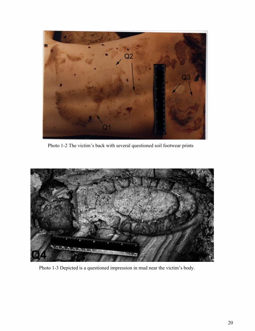
Evidence Submitted: A crime scene photograph of the victim’s back with several questioned footwear
impressions made of blood, dust, dirt or soil, a crime scene photograph of a questioned footwear
impression in mud near the victim’s body, one Dentstone® cast of the questioned footwear impression
in mud, and one pair of the suspect’s size 11 Texas Steer® shoes designated K1.
Request: Determine if the known pair of the designated K1 (see Photo 1-1) is the source of the
questioned footwear impressions on the victim’s back and in the mud near the victim’s body.
Collected Data: Life size (1:1) photographs of the questioned dirt footwear impressions present on the
victim’s back were made. The photographs were directly compared to the outsoles of the suspected
known shoes K1. The visual and macroscopic examination and comparison of the questioned footwear
prints on the victim’s back with the known outsoles represented by K1 divulged that the questioned
prints in Photo 1-2 (Q1- Q3) were dissimilar in all class characteristics to the known shoes
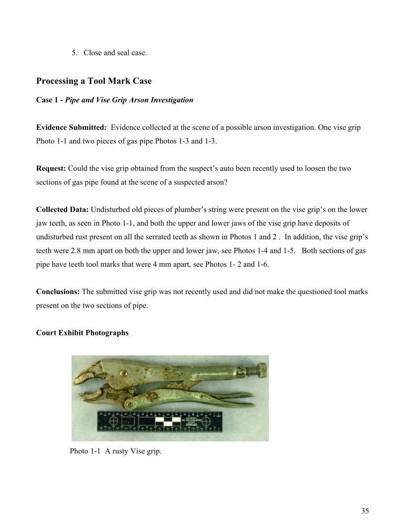
An examination of the crime scene photograph of the impression in the mud near the body Q4 and the
Dentstone cast® of the impression Q5 collected at the crime scene revealed the presence a left footwear
impression containing a Texas Steer® logo and outsole design see Photos 1-3 and 1-4.
An impression of the suspect’s left shoe was made in mud and cast with Dentsone®, see Photo 1-5.
Next a direct comparison was made with the known cast K1 left to the Dentstone cast® of the

19
impression Q5 imprint made in mud see Photo 1-6. The questioned imprints Q1 to Q5 class
characteristics i.e., outsole thread design, size, logo, and so on were examined and compared to the K1
left cast. All the collected data was used to form the examiner’s stated conclusion.
Conclusions: In the opinion of the examiner the questioned soil footwear prints present on the
victim’s back Q1-Q3 and the questioned impression in the mud near the victim’s body Q4 & Q5 were
not made by the suspect’s known shoe K1 left. Testimony was given in court stating these conclusions.
Court Exhibit Photographs
Photo 1-1 The outsole pattern of the suspect’s size 11 Texas Steer® shoes.
20
Photo 1-2 The victim’s back with several questioned soil footwear prints
Photo 1-3 Depicted is a questioned impression in mud near the victim’s body.

21
Photo 1-4 Cast of the questioned mud impression located near the victim’s body.
Photo 1-5 Known impression of suspect’s K1 left shoe made in mud.

22
Photo 1-6 Comparison of the Questioned cast made at the crime scene and the Dentstone ® cast made of the suspect’s K1 left shoe.
Case 2 - Execution of Two Police Officers a during Gun Buy Operation - Homicide Investigation
Evidence Submitted: One section of black colored 6” diameter pipe with several overlapping footwear
prints see Photo 2-1, and the outsole pattern of one pair of Diadora® brand, black sneakers, size 11½,
designated (K1) as seen in Photo 2-2.
Request: Determine if the known pair of sneakers designated K1 is the source of the questioned white
colored footwear impressions present on the black pipe.
Collected Data: Visual and macroscopic examination of the 6” black pipe with oblique illumination
reveals the presence of two questioned white colored, partial, negative footwear prints. One of the
questioned partials footwear prints appears to be that of a right sneaker designated Q1 and one of the

23
questioned partials footwear prints appears to be that of a left sneaker designated Q2 as seen in Photo 2-
3.
Known overlays were prepared of the outsole patterns of the K1 sneakers, see Photo 2-4. The overlays
were than compared to the questioned prints on the pipe. Class characteristics such as outsole thread
design, size, and logo were examined and compared to the K1 overlays and the questioned footwear
prints. Wear patterns and accident characteristics were evaluated and assessed. All the collected data
was used to form the examiner’s stated conclusion.
Conclusions: In the opinion of the examiner one of the questioned footwear impressions Q1 found on
the pipe’s surface could have been made by K1 left, and one of the questioned footwear impressions Q2
found on the pipe’s surface could have been made by K1 right. Testimony was given in court stating the
author’s conclusions.
Court Exhibit Photographs
Photo 2-1 One section of black pipe

24
Photo 2-2 Outsole patterns of K1 Diadaro® brand black sneakers.
Photo 2-3 The questioned prints found on the pipe’s surface.

25
Photo 2-4 Overlays made from known K1 sneakers. Case 3 - Homicide Investigation
Evidence Submitted: An old woman was standing on the sidewalk waiting to cross the street when a
female assailant, pushed her to the sidewalk and beat her by punching and kicking her until she was no
longer moving. She then proceeded to take her belongings. Two pieces of concrete side walk and
several photographs of two different questioned footwear imprints made from apparent blood present on
a concrete sidewalk at the scene of a homicide. One extremely worn pair of sneakers, manufacture
unknown.
Request: Determine if the known pair of sneakers designated K1 is the source of the two questioned
footwear blood prints present on the concrete sidewalk designed Q1 and Q2.
Collected Data: Visual examination of the concrete sections of sidewalk with oblique illumination
reveals the presence of two questioned reddish brown, dried partial, residual footwear prints. The prints
were photographed and enhanced with a solution made of crystal violet reagent (not shown).

26
Known overlays were prepared of the outsole patterns of the K1 sneakers, see Photo 3-1 (center). The
overlays were than compared to the Q1 and Q2 questioned prints present on the concrete blocks depicted
in Photo 3-1, Q1 (left) and Q2 (right). Next, the class characteristics such as outsole thread design, and
size, were examined and compared to the K1 overlays and the questioned footwear prints. The wear
patterns configuration and accident characteristics were evaluated and assessed. All the collected data
was used to form the examiner’s stated conclusion. The class characteristics and wear pattern
configuration present in K1 were found to be consistent with the corresponding features exhibited in
both questioned prints. No corresponding accidental features were observed between the known and
questioned prints.
Conclusions: In the opinion of the examiner both of the questioned residual footwear blood imprints
designated Q1 and Q2 could have been made by the K1 right sneaker, see Photo 3-1.
Court Exhibit
Photo 3-1 – Court display showing the two questioned prints Q1 (left) and Q2 (right) and the known overlay print made from the right sneaker K1.

27
Case 4 – Burglary Investigation
Evidence Submitted: A burglary was committed in a Manhattan apartment. When the apartment’s
occupant arrived home from work and entered her kitchen area she notices a white piece of sandwich
bread on the floor. She picked up the slice of bread and observed what appeared to be a shoe heals print
impression on the bread’s surface. Upon entering her bedroom she realized her apartment had been
burglarized. The woman notified the police. During their investigation the investigating officer
determined that there was no signs entry into the apartment. He asked the woman if they was a building
Superintendents with keys to all the apartments? There was, so the officer questioned the man and
noticed he was wearing shoe. The officer further questioned the man, and then arrested him for
burglary. The officer submitted the suspect’s shoes and the slice of white bread, see Photo 4-1.
Request: Determine if the known pair of shoes designated K1 is the source of the questioned footwear
impression on the slice of bread designated Q1.
Collected Data: Visual examination of the slice of bread revealed the presence of a reversed, right shoe,
heal print marked “Stuart Holmes.” Next, the class characteristics such as the brand name, heal logo,
thread pattern and design, size, wear pattern configuration and accidental marks were assessed and
evaluated. All the collected data was used to form the examiner’s stated conclusion. The class
characteristics and wear features present in K1Right were found to be consistent with the corresponding
features exhibited in the questioned imprint present on the slice of white bread. No corresponding
accidental features were observed between the known and questioned.
Conclusions: In the opinion of the examiner the questioned heal imprint designated Q1 could have
been made by the K1 right shoe heal, see Photo 4-1.
Court Exhibit

28
Photo 4-1 - Court display showing the questioned prints Q1 (on left) and the known right shoe heal K1Right (on right). Case 5 – Double Homicide Investigation
Evidence Submitted: A double homicide was committed in a Brooklyn apartment. An elderly couple
was beaten to death by unknown assailant(s). When the elderly couple’s son went to the apartment to
check up on his parents (as it was his daily custom) he discovered the apartment’s door ajar. Upon
entering the apartment he found his parent’s lifeless bodies lying face down, on the floor, in pools of
blood. The man immediately notified the police. During the investigation the detective determined that
there were no signs of entry into the apartment. The office processing the crime scene discovered an
envelope addressed to the couple when he moved the woman’s body. The envelope appeared to have a
bloody footwear imprint on the back of the envelope. The couple’s son told the investigator that the
next door neighbor (a young woman) normally picked up the couples’ mail and delivered it to them.
The detective knocked on the neighbor’s door and asked the young woman if she had noticed anything
unusual when she delivered the couples mail. She denied delivering the mail. The detective noticed
what appeared to be a small blood stain on the woman’s white sneaker. Upon further questioning he
arrested the young woman and her girlfriend. The investigating officer submitted the suspect’s sneakers
and the envelope with the bloody residual footwear print.

29
Request: Determine if the known pair of sneakers designated K1 is the source of the questioned bloody
footwear imprint on the envelope designated Q1.
Collected Data: A visual examination of the envelope disclosed the presence of one partial bloody
right sneaker print on the white envelope’s back surface designated Q1 which was compared to known
imprints made from the K1 right sneaker. Next, the class characteristics such as the right sneaks thread
and design pattern, size, wear pattern configuration and accidental marks were assessed, evaluated and
compared to K1 knowns. The class characteristics, wear pattern configuration and random accidental
markings present within the known test prints made by K1 right were found to be consistent with the
corresponding features exhibited in the questioned imprint Q1 present on the white envelope.
Conclusions: In the opinion of the examiner the questioned heal imprint designated Q1 was made by the K1 right sneaker, see Photo 5-1. Testimony was given in court stating the author’s conclusion.
Court Exhibit
Photo 5-1 Shown above is a court display depicting the similarities in class characteristics and wear pattern configuration between the questioned prints Q1 (on left) and the known right sneaker print K1 (on right). Twelve (12) randomly occurring accidental marks are noted for K1 and Q1. Testimony was given in court stating the author’s conclusion.

30
Tool Marks General SOP for Tool mark Examination in an ASCLAD Accredited Laboratory
Purpose of this SOP is to process evidence for the presence of questioned tool mark impression(s) and / or to compare a questioned tool mark impression(s) to known tool mark test impressions when available. Upon receipt of evidence to determine the presence of tool mark impression(s) and/ or to compare questioned tool mark impression(s) to known tool mark impressions. General guidelines for tool mark examination and comparison can be found in the forensic literature: 6
1. Preparation of Control Tool mark Impression:
i. Tool mark comparisons require the examiner to compare the: class characteristics, subclass, wear patterns, and individual or accidental characteristics comprising the known or control specimens made from the known tool mark with to the question tool marks recovered from the crime scene.
j. Before test tool marks were made with the questioned tool it must be examined for trace
evidence, i.e. paint smears or chips, metal shavings, DNA or fingerprints. Any trace evidence present on the tools surface should be photographed, fully removed and preserved.
k. Control or test tool marks made from suspected tool(s) can be made in various ways,
depending on the need of the analyst. A few of these procedures were as follows:
l. The material the questioned tool mark(s) were made on and the shape of the object the tool marks were present on often dictates the materials used to make the test tool marks.
m. If the questioned tool marks were present on soft surfaces such as wood, plastic, painted
surface and so on, the test tool marks can be made on the same type of material as the questioned mark is found. After closed study and observation of the questioned marks the analyst should attempt to reproduce the questioned marks on the test material by applying the subject tool to the test material in the manner the analyst believe the questioned marks were created.
n. Test tool marks can be made directly on soft lead sheet(s) or pieces of lead sheeting wrapped
around pipe(s).
o. Test tool marks can be made directly on soft lead sheet(s) or pieces of lead sheeting wrapped around pipe(s).
p. In cases involving wire cutters, cable cutters and similar tools, the test tool marks can be
made directly on strands of thin gauge wire or cable made from copper or aluminum. q. Test tool marks can be made directly on modeling wax sheets of varying hardness or pieces

31
of modeling waxes produced in the shape of cylinders or blocks. r. Test tool marks can be made directly on modeling clays of varying hardness.. s. Test tool marks can be made directly on pieces of textiles, and leather.
t. Test marks should be clearly marked for identification with a Sharpie® marker or diamond scribes. The unique identifier, test mark number, tool used, date and initials of the individual preparing the test tool marks.
Demonstrated in Figures 14 -16 are some of the processes used to produce standard tool marks from known subject tools for the purpose of utilizing them in comparison with questioned tool marks obtained from scenes of crime.
Figure 14 – Preparation of screwdrivers tool marks standards being made on a piece of lead sheet.

32
An engraver’s tool sharpening holder with a variable height adjustment and two angle adjustments holds the test tool to make exemplar tool marks in the manner suggested by Burd and Kirk.7
Figure 15 – Preparation of known test impression made test tool marks made in No. Roma® Plastilina sculpting clay of various screw driver tips.
Figure 16 – Preparation of known test impression of a ball-peen hammer on a block of red sculpture
wax.

33
2. Initial Processing of Questioned Tool mark(s):
f. Examine each questioned item of evidence for the presence of tool mark impression(s) using
oblique illumination. If impression(s) were found or suspected, examine impression(s) under low magnification using a magnifying glass if appropriate. Record item(s), location(s) and appearance of impression(s). Photograph impression(s) if appropriate.
NOTE: An appropriate scale (NIST™ traceable) can be placed in the field of view when performing any photographic techniques. Additionally, when possible, all comparative examinations should be performed on a one-to-one scale.
g. Record a description of any tool mark impression(s) found on evidentiary items. If no tool mark impressions of value were found or if no tool mark for comparison were submitted, close case and seal, otherwise proceed to Tool mark Impression Comparison section of this procedure.
h. Typically, the examiner is asked to determine if a questioned tool mark(s) was made by a
particular tool mark.
i. Normally this is accomplished by evaluating and comparing the class characteristics, subclass characteristics, wear patterns and accidental features composing both the questioned and known marks(s).
3. Enhancing Questioned Tool mark Prints Photographic:
d. Questioned marks made on surfaces at the scenes of crime were the most common form of tool mark(s) evidence received in this laboratory.
e. Photographic any questioned tool mark(s) found on the substrate item. This is done with
digital photography. Overall, intermediate, close-up and macro photographs should be taken when necessary.
f. Cast of both questioned and known test tool marks can be made with Mikrosil® silicone casting material. A one to one mixture of the two components were thoroughly mixed with a spatula and quickly applied to the subject tool mark. The mixture is allowed to set until dried. The cast is carefully removed from the substrate material.
Shown in Figure 17 is the use of Adobe Photoshop spotlight effects command to look into the interior of a test tool mark made in No. Roma® Plastilina sculpting clay

34
Figure 17 – A Roughneck® pry bar; the numbers number designation about the tool correspond to the numbered test tool marks made in No. Roma® Plastilina sculpting clay. The Adobe Photoshop spotlight effects command was used to light up the inside of tool mark #2 on the clay block (bottom right).
4. TOOL MARK IMPRESSION COMPARISON
1. Prepare tool mark test prints from the submitted evidentiary tool mark using the appropriate technique.
2. Compare known tool mark and/or to questioned tool marks(s) by examining both with a
stereomicroscope and a comparison microscope.
2. Compare and record the class characteristics, subclass characteristics, wear patterns and any accidental characteristics appearing on the questioned tool mark to the known test tool mark.
3. Determine and record if the known tool can be included or excluded as a source of the
questioned tool mark(s). 4. Determine and record if the known tool mark can be individually associated to the
questioned tool mark
35
5. Close and seal case.
Processing a Tool Mark Case Case 1 - Pipe and Vise Grip Arson Investigation
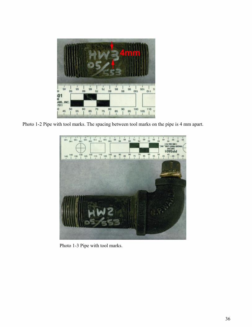
Evidence Submitted: Evidence collected at the scene of a possible arson investigation. One vise grip
Photo 1-1 and two pieces of gas pipe Photos 1-3 and 1-3.
Request: Could the vise grip obtained from the suspect’s auto been recently used to loosen the two
sections of gas pipe found at the scene of a suspected arson?
Collected Data: Undisturbed old pieces of plumber’s string were present on the vise grip’s on the lower
jaw teeth, as seen in Photo 1-1, and both the upper and lower jaws of the vise grip have deposits of
undisturbed rust present on all the serrated teeth as shown in Photos 1 and 2 . In addition, the vise grip’s
teeth were 2.8 mm apart on both the upper and lower jaw, see Photos 1-4 and 1-5. Both sections of gas
pipe have teeth tool marks that were 4 mm apart, see Photos 1- 2 and 1-6.
Conclusions: The submitted vise grip was not recently used and did not make the questioned tool marks
present on the two sections of pipe.
Court Exhibit Photographs
Photo 1-1 A rusty Vise grip.
36
Photo 1-2 Pipe with tool marks. The spacing between tool marks on the pipe is 4 mm apart.
Photo 1-3 Pipe with tool marks.

37
Photo 1-4 Vise grip with undisturbed traces of old twine and serrated teeth with undisturbed deposits of rust on lower jaw.

38
Photo 1-5 Depicted is a vise grip with undisturbed deposits of rust on the jaws.
Photo 1-6 Shown is the opposite side of pipe in Photo 1-3. Spacing between teeth tool marks on the pipe are 4 mm apart.
Case 2 - Narcotics Investigation/Textile Impression
Evidence Submitted: During a narcotics investigation, a team of narcotics undercover officer carried
out a search warrant in the suspect’s apartment which on the 5th floor of an apartment house. The search
warrant only allowed the officers to search the suspect’s bedroom. After the search, while exiting the
building one of the officer noticed a small pistol lying on the ground directly under the suspect’s
apartment window. The officers obtained a news search warrant for the suspect’s living. The officers
returned to the suspect’s apartment and searched the suspect’s living room couch (where the suspect had
been previously been sitting during the first search. The officers discovered that an impression of a
small pistol was embedded in the textile under the sofa’s top cushion. A section of the upholstery fabric
with the impression was removed and forwarded for comparison with one “Davis Industries” P-32
pistol (Q1) found 5 floors below suspect’s living room window in grass (see Photo 2-1).

39
Request: Could the questioned pistol (Q1) be the source of the impression (K1) found underneath the
top cushion, embossed in the sofa upholstery collected in the course of a search pursuant to the arrest of
a suspected drug dealer during a buy/bust operation?
Collected Data: Both the questioned (Q1) pistol and the known (K1) impression were examined
separately. First the pistol was processed for the presence of fibers. One black fiber consistent in all
chemical and physical properties to the black colored fibers composing the sofa’s upholstery is found on
the pistol. Next the pistol and impression in the textile were examined for design features. Linear and
angular measurements of both were made. Photo 2-2 demonstrates that all the obtained measurements
and design features present on both specimens. Finally, a photographic overlay is made of the pistol and
placed directly over the K1 impression on the textile as shown in Photo 2-3.
Conclusions: It was reported that the K1 impression present on the textile was consistent with having
been made by the Q1 P- 380 pistol.
Court Exhibit Photographs
Photo 2-1 On the left, the piece of upholstery with an impression of a pistol (K1), and on the right, the pistol (Q1) obtained during the search of the grass below the suspect’s living room window.

40
Photo 2-2 The angular and linear measurements and design features observed for the impression and the pistol were found to be consistent in all respects, except for the absence of presence of impression of a trigger guard and magazine release.

41
Photo 2- 3 The overlay of the Q1 pistol as it appears placed directly over the K1 impression on the upholstery. This type of image processing can easily be done with Adobe Photoshop®.
Case 3 – Burglary Investigation
Evidence Submitted: A man arrives home after work and discovered that his home had been
burglarized. The rear screen storm door of his home was apparently cut opened. He called the local
police. The responding officer took down the details and decided to search the area. He knocked on the
next door neighbor’s door. A young man answers the door. When questioning the young man (who
appeared high on something) as to whether he had seen any suspicious persons in the neighborhood he
spotted a piece of screen inside the premises. After questioning the young man about the piece screen
he arrested him for burglary. The questioned piece of screen, designated Q1, and the screen door from
the victim’s home, designated K1, were forwarded for comparison.
Request: Could the questioned piece of screen found in the suspect’s home Q1 be from the victim’s
damaged screen door K1?
Collected Data: First, several tiny pieces of screen from Q1 and K1 were examined with x-ray
fluorescence to determine their elemental composition. Each was found to be composed of aluminum
metal. The physical makeup of Q1 and K1 were studied and found to be the same. Finally, the Q1 piece
of screen was jig-sawed into the known screen door K1.

42
Conclusions: It was reported that the Q1 section of aluminum screen was cut out of the from the K1 aluminum screen door, see the images of Q1 and K1 in Photo 3-1.
Photo 3-1 Shown is the jig-saw match between the Q1 piece of screen from the suspect’s home and the known back screen door from the victim’s home K1.

43
Case 4 – 1st Degree Assault Investigation
Evidence Submitted: A man was arrested jumping a subway turnstile in order to beat the fare. He was
apprehended by several officers, held down with one of the officer’s baton, given a summons and
released. Several hours later the man went to a local hospital for medical aid. At the hospital the man
claimed the officers had violently attacked him by pushing a baton, through his underpants and into his
anus causing him severe injury. An investigation was conducted and the offices were arrested and
indicted. The officers and their work lockers were all searched, and over 150 objects confiscated i.e.,
wooden batons, rubber batons, metal batons, flash lights, radio antennae and so on. All of the objects
and the complainant’s damaged underwear were forwarded for examination.
Request: Could any of the known objects obtained from the officers and /or their work lockers’ been
used to cause the damage found on the complainant’s underpants?
Collected Data: First, in the presence of several witnesses the under pants were removed from their
sealed paper evidence container (brown Kraft bag) examined and immediately photographed. Upon
examination, it was instantaneously realized that the hole in the textile was square. The tread
surrounding the perimeter of the hole appeared slightly pulled; however, their ends were cut as if
someone had used a punch like devices to make the hole. In addition several square shaped , blood
colored imprints, having prominent borders was found on the garment near the square hole. The hole
was measured with a calibrated stereo microscope ocular micrometer and found to be 1/2” square, see
Photo 4-1. All of the objects were examined and tested to determine if any of them could have made the
hole present in the garment. All of the objects had round ends, it was determined that the questioned
hole could not have been produced by any of these known objects.
An inquiry was conducted by the author to determine the nature of the object which could have
produced the hole and square blood colored stains on the undergarment. It was determine that the likely
implement was a stainless steel, ½” square tattoo machine dye needle, see Photo 4-2.
Conclusions: In court testimony, it was reported that the questioned hole in the garment was not made by
any of the objects obtained from the officers and their lockers’. All the officers were found not guilty.

44
Photo 4-1 The rear of the garment showing the questioned square hole.

45
Photo 4-2 On the right, is depicted a tattoo machine needle which could have easily produced the hole and blood colored stains present on the rear of the undergarment. Case 5 – Gas Explosion Homicide Investigation
Evidence Submitted: A landlord had been unsuccessfully trying to evict an old woman from her rent
controlled apart for years. A gas explosion occurred at the location and the old woman was killed. The
arson investigator suspected foul play, obtained two search warrants, and searches the building’s
basement and the landlord’s home. Two sections of gas pipes with apparent tool marks were forwarded
for examination. One section designated (Q-1a) recovered in the building’s basement where the
explosion occurred, and one section was recovered from the landlord’s basement designated (K-2a),

46
Request: Determine if the tool marks on the known gas pipe (K-2a) were consistent with the tool marks
present on the questioned gas pipe (Q-1a).
Collected Data: All of the tool mark impressions present on the Q-1a pipe were carefully examined
with a stereomicroscope under 4X to 20X magnification. The class patterns present on the Q-1a pipe
were consistent with marks left by a pipe wrench as demonstrated in Photo 5-1). Linear and angular
dimensions of the circled (Red) pipe tooth impression on the Q-1a section of pipe were measured with a
calibrated ocular micrometer and a protractor ocular micrometer. The dimensions were noted in Photo
5-2.
Next, all of the tool mark impressions present on the K-2a pipe were carefully examined with a
stereomicroscope under 4X to 20X magnification. The class patterns present on the K-2a pipe were
consistent with marks left by a pipe wrench (see Court Exhibit Photo 1). Linear and angular dimensions
of the circled (Red) pipe tooth impression on the K2-a section of pipe were measured with a calibrated
ocular micrometer and a protractor ocular micrometer the dimensions were noted in Photo 2. Both the
questioned and known circled tooth impressions were found to have the same class features and
dimensions. Both singled out tooth impressions in Q-1a and K-2a had the shape of a parallelogram,
having two sets of equal length, parallel, opposite sides. The questioned (Q-1a) and known (K-2a) tooth
mark impressions were compared on a comparison microscope. Both tooth impressions were found to
possess the same patterns of accidental striation features, as seen in the superimposed images of the Q-
1a and K-2a pipe wrench tooth impressions shown in Court Exhibit Photo 5-3.
Conclusions: In the opinion of the examiner both the questioned gas pipe Q1a, and the known gas
pipe K2a possessed tool marks made with the same pipe wrench.
Court Exhibit Photographs

47
Photo 5-1 Two gas pipes, one (Q-1a) from the scene of a homicide and gas explosion investigation, and one gas pipe with known tool marks made with a wrench from the landlord’s basement (pipe marked K-2a).
Photo 5-2 A comparison of the linear and angular dimensions of the Q-1a tooth impression (top) and the K-2a tooth impression (bottom). Two sets of parallel sides were found to be present. One set of sides were 337µm in length and the second set of parallel sides were 261 µm in length. The opposite angles were also equal. The smaller set of angles is 46º and the second set is 134º.
Photo 5-3 Comparison microscope photomicrograph showing one tooth mark on the K-2a pipe overlapped with one tooth mark on the Q-1a pipe. Note the corresponding accidental striation patterns in both specimens.

48
Statistical Analysis of Impression Evidence Over the course of the last two decades, DNA profiling has grown to be one of the most widely known
and applied techniques for the identification of biological samples in forensic science. Arguably, the
success of DNA profiling techniques is responsible for the courts’ current interest in the raising of
standards for scientific examination of all forms of physical evidence (e.g. tool marks, soils, fingerprints,
gunshot residue, etc.). It is undoubtedly the clear applicability of simple statistical methods to DNA
profiling techniques which lies at the core of their success. The question remains however; how can
statistical methods be applied to other forms of physical evidence? To address this question, below we
briefly review several methods for objective, numerical computational pattern matching which can be
applied to tool marks and footwear.
Industries, particularly those that employ some type of sorting into categories, face similar problems as
those faced in the examination of physical evidence in forensic science. They have been applying
statistical pattern recognition techniques for the automation of assorted classification tasks for
approximately the last half century 8-13.
The starting point for the statistical analysis and comparison of any set of patterns is the collection of
features of the pattern in question. Every measurement of a feature is a random variable Xi. Collection of
various features into a list constitutes the feature vector, x for that pattern. The feature vector may
consist of anywhere from 1 component (one-dimension or 1D-univariate feature) to n-components (n-
dimensional or nD-multivariate features).
Once extracted the feature vectors can be subjected to a myriad of statistical pattern recognition
methodologies depending on their dimensionality. The techniques fall into two broad categories,
univariate for 1D features and multivariate for 2D and greater features. Univariate techniques are usually
based around a 1D feature statistic which is a measure of similarity between two pattern (so called
“score based” techniques). An example for comparing striated tool marks appears below:

49
Figure 18 - Illustration of a univariate “max-ccf” similarity score based approach for associating patterns. Green shows a sample of max-ccf score for known matches (KM). Pink shows a sample of max-ccf scores for known non-matches (KNM) Figure18 shows a maximum cross correlation metric applies to a sample of striated toolmarks compared
a pair at a time. Cross correlation computes a series of correlation coefficients as two patterns are
translated with respect to one another, and ranges on a scale of -1 to 1. The maximum of these values
(max-ccf) is a measure of similarity between the two patterns.
The pink histogram represents a sample of scores for tool marks known not to have been made by the
same tools. The green histogram shows a sample of scores for tool marks known to have been made by
the same tool. Cut-off scores can be introduced such that when two patterns are compared, the algorithm
renders an opinion that they were generated by the same tool (or shoe in the case of footwear). Below
this threshold the algorithm renders an opinion of exclusion (i.e. not a “match”).
Multivariate techniques can also be used to perform a comparison task for tool marks and footwear
evidence. In combination with probability theory, they can also be used to render a metric as to “how
good” the “matches” they propose are. Petraco et al. 14-15 have found that the support vector machine
(SVM) discrimination algorithm combined with PCA to be a well multivariate statistical pattern
recognition technique for forensic pattern discrimination. SVMs attempt to find efficient decision rules
by determining maximum margins of separation between classes of objects.

50
Conformal prediction can be used in combination with PCA-SVM to put rigorous levels of confidence
on each pattern identification output by the algorithm. 16
The way the method works is actually very simple. Given a training set of striation patterns with known
identities (called a bag) and at least one pattern of unknown identity, an estimate of randomness is
computed for the bags containing the unknown pattern with all possible labels for its identity. A (1-α) x
100% confidence interval for the patterns’ identity is then found from the set of p-values computed
using this process.
An example of the confidence prediction for tool marks in action appears in Figure 2. One thousand
three hundred real and simulated screwdriver mean profiles derived from 3D confocal microscopy data
from 58 screwdrivers were identified by the conformal prediction at the 95% level of confidence. This
means that the ID of each unknown tool mark is output (right or wrong) with 95% confidence. The
system should then produce misidentifications at a rate of about 5%. This is indeed the case as can be
seen from Figure 19.
Figure 19- Shown is a 95% confidence plot for identification of unknown tool marks. For such a plot the slope of the empirical error rate line should be about 5%.
A testable Bayesian alternative to conformal prediction for algorithm-made ID “sure-ness” can be
implemented with Efron’s Empirical Bayes methodology. 17 Modern machine learning methods output

51
a voluminous amount of information when executing a discrimination task. Such a large amount of
derived data can be used to harness powerful Bayes theorem-based methods to compute posterior match
probability (also called the local true discovery rate). Such a quantity is the algorithm’s degree of belief
in the “match” once it has been presented with the pattern data (feature vector) from a relevant
population of possible patterns.
Bayesian hierarchical Poisson regression, carried out with Markov Chain Monte Carlo (MCMC)
sampling, can be used to fit this “match” probability model. The MCMC sampling procedure also allows
for the determination of uncertianty intervals around the estimated posterior match probabilities. An
example posterior random match probability (RMP =1 - posterior match probability) plot for
screwdriver mean profiles appears in Figure 20.
Figure 20- Plot of posterior estimated RMPs for patterns identifies with PCA-SVM. This decision model is operating at an acceptable level; the empirical error rate is 0% and the vast majority of the IDs have very low RMPs. The low RMP (<10%) “matches” can be judged as “high quality” hits in a probabilistic sense. Any “matches” above that are judged as “low” to “very low” quality and thus very uncertain.

52
References
1. Petraco, N. and Sherman, Hal, Illustrated Guide to Crime Scene Investigation, CRC Press, Boca Raton, FL. 2006.
2. Abbott, J. R., Footwear Evidence, Germann, A.C., Ed. Springfield, Ill., Charles C.
Thomas, 1964. 3. Cassidy, M. J., Foootwear Identification. Royal Canadian Mounted Police, Ottawa, 1980.
4. Bodziak, W. J., Footwear Impression Evidence, 2nd ed., CRC Press, Boca Raton, FL,
2000. 5. Petraco, N. and Resua, R. A Rapid Method for the Preparation of Transparent Footwear
Test Prints, J. F. S., 24, 4, pp. 935-37, 1982.
6. Petraco, N., Color Atlas of Forensic Toolmark Identification, CRC Press, Boca Raton, FL, 2011.
7. Burd, D.Q., and Kirk, P.L., Toolmarks: Factors involved and their comparison and use as
evidence, J. Crim. Law Criminology, Vol. 32, pp. 679-86, 1942.
8. Petraco N, Petraco N.D.K. and Pizzola, PA., An Ideal Material for the Preparation of Tool mark Test Prints, J. F. S., 50, 6, pp. 1407-10, 2005.
9. Bhagat, P. Pattern Recognition in Industry. 1 ed. Amsterdam: Elsevier, 2005.
10. Duda,R.O., Hart, P.E., and Stork, D.G.. Pattern Classification. 2 ed. New York: Wiley,
2001.
11. Theodoridis, S. and Koutroumbas, K., Pattern Recognition. 3 ed. San Diego: Academic Press, 2006.
12. Fukunaga, K., Statistical Pattern Recognition. 2 ed. San Diego: Academic Press, 1990. 13. Bishop, C.M., Pattern Recognition and Machine Learning. 1st ed. New York: Springer,
2006. 14. Petraco, N.D.K., Chan, H., De Forest, P., Diaczuk, P., Gambino, C., Hamby, J.,
Kammerman, F., Kammrath, B., Kubic, T., Kuo, L., McLaughlin, P., Petillo, G., Petraco, N., Phelps, E., Pizzola, P., Purcell, D. and Shenkin, P. Application of Machine Learning to Tool marks: Statistically Based Methods for Impression Pattern Comparisons. NIJ Report: 2009-DN-BX-K041.

53
15. Petraco, N.D.K, Kuo, L., Chan, H., Phelps, E., Gambino, C., McLaughlin, P.,
Kammerman, F., Diaczuk, P., Shenkin, P., Petraco, N., and Hamby, J. Estimates of Striation Pattern Identification Error Rates by Algorithmic Methods. AFTE J, 45(3):235-244 (2013)
16. Vovk, V., Gammerman A. and Shafer, G., Algorithmic learning in a random world. 1st
ed. Springer, New York, 2005. 17. Efron, B., Large-Scale Inference: Empirical Bayes Methods for Estimation, Testing, and Prediction. New York: Cambridge University Press, 2010.


![Accurate 3D Footwear Impression Recovery From Photographs€¦ · Accurate 3D Footwear Impression Recovery From Photographs ... nosaur footprints [17]. Table 1 summarizes the three](https://static.fdocuments.net/doc/165x107/5f0780767e708231d41d4c34/accurate-3d-footwear-impression-recovery-from-photographs-accurate-3d-footwear-impression.jpg)