Implications for Conventional and Expandable Hanger Assembly
15
energies Article Investigation of Elastomer Seal Energization: Implications for Conventional and Expandable Hanger Assembly Harshkumar Patel and Saeed Salehi * Mewbourne School of Petroleum and Geological Engineering, University of Oklahoma, Norman, OK 73071, USA; [email protected] * Correspondence: [email protected]; Tel.: +1-405-325-6829 Received: 16 January 2019; Accepted: 22 February 2019; Published: 25 February 2019 Abstract: Elastomer seals are extensively used in various wellhead and casing/liner hanger equipment as barriers for isolating fluids. Seal assemblies have been identified as one of the major cause of well control incidents. Majority of hangers utilize conventional weight- or mechanical-set slip-and-seal assembly. The objective of this paper is to conduct a detailed investigation of seal energization in conventional and relatively newer expandable type hanger seal assembly. To achieve the objective, the finite element modeling approach was employed. Three dimensional computer models consisting of concentric casings and annular elastomer seal element were constructed. Seal energization process was modelled by manipulating boundary conditions. Conventional seal energization was mimicked by applying rigid support at the bottom of elastomer element and compressing it from the top. Expandable hanger type seal energization was modelled by radially displacing the inner pipe to compress annular seal element. Seal quality was evaluated in terms of contact stress values and profile along the seal-pipe interface. Different amounts of seal energization were simulated. Both types of seal energization processes yielded different contact stress profiles. For the same amount of seal volumetric compression, contact stress profiles were compared. In case of conventional seal energization, contact stress profile decreases from the compression side towards support side. The seal in expandable hanger generates contact stress profile that peaks at the center of contact interface and reduces towards the ends. Convectional seal assembly has more moving parts, making it more prone to failure or under-energization. Finite Element Models were validated using analytical equations, and a good match was obtained. The majority of research related to elastomer seal is focused on material properties evaluation. Limited information is available in public domain on functional design and assessment of seal assembly. This paper adds novel information by providing detailed assessment of advantages and limitations of two different seal energization process. This opens doors for further research in functional failure modes in seal assembly. Keywords: elastomer seal; finite element analysis; contact pressure; sensitivity analysis; well integrity; liner hanger 1. Introduction Elastomer is a cross-linked network of natural or synthetic polymers. Elastomer material is relatively cheaper and exhibits characteristics property of deforming and recovering under load (elasticity and resilience). Moreover, elastomer seals are suitable for dynamic application [1] and their sealability does not depend on surface characteristic like metal-to-metal seal [2]. Because of these advantages, elastomer material is still widely used in various drilling, completion, and wellhead equipment. In addition to packers, blow-out preventers, and safety valves, elastomer seals is a critical component of casing and liner hanger assemblies. Energies 2019, 12, 763; doi:10.3390/en12040763 www.mdpi.com/journal/energies
Transcript of Implications for Conventional and Expandable Hanger Assembly

energies
Article
Investigation of Elastomer Seal Energization:Implications for Conventional and ExpandableHanger Assembly
Harshkumar Patel and Saeed Salehi *Mewbourne School of Petroleum and Geological Engineering, University of Oklahoma, Norman, OK 73071,USA; [email protected]* Correspondence: [email protected]; Tel.: +1-405-325-6829
Received: 16 January 2019; Accepted: 22 February 2019; Published: 25 February 2019�����������������
Abstract: Elastomer seals are extensively used in various wellhead and casing/liner hangerequipment as barriers for isolating fluids. Seal assemblies have been identified as one of the majorcause of well control incidents. Majority of hangers utilize conventional weight- or mechanical-setslip-and-seal assembly. The objective of this paper is to conduct a detailed investigation of sealenergization in conventional and relatively newer expandable type hanger seal assembly. To achievethe objective, the finite element modeling approach was employed. Three dimensional computermodels consisting of concentric casings and annular elastomer seal element were constructed. Sealenergization process was modelled by manipulating boundary conditions. Conventional sealenergization was mimicked by applying rigid support at the bottom of elastomer element andcompressing it from the top. Expandable hanger type seal energization was modelled by radiallydisplacing the inner pipe to compress annular seal element. Seal quality was evaluated in terms ofcontact stress values and profile along the seal-pipe interface. Different amounts of seal energizationwere simulated. Both types of seal energization processes yielded different contact stress profiles. Forthe same amount of seal volumetric compression, contact stress profiles were compared. In case ofconventional seal energization, contact stress profile decreases from the compression side towardssupport side. The seal in expandable hanger generates contact stress profile that peaks at the centerof contact interface and reduces towards the ends. Convectional seal assembly has more movingparts, making it more prone to failure or under-energization. Finite Element Models were validatedusing analytical equations, and a good match was obtained. The majority of research related toelastomer seal is focused on material properties evaluation. Limited information is available in publicdomain on functional design and assessment of seal assembly. This paper adds novel informationby providing detailed assessment of advantages and limitations of two different seal energizationprocess. This opens doors for further research in functional failure modes in seal assembly.
Keywords: elastomer seal; finite element analysis; contact pressure; sensitivity analysis; well integrity;liner hanger
1. Introduction
Elastomer is a cross-linked network of natural or synthetic polymers. Elastomer material isrelatively cheaper and exhibits characteristics property of deforming and recovering under load(elasticity and resilience). Moreover, elastomer seals are suitable for dynamic application [1] and theirsealability does not depend on surface characteristic like metal-to-metal seal [2]. Because of theseadvantages, elastomer material is still widely used in various drilling, completion, and wellheadequipment. In addition to packers, blow-out preventers, and safety valves, elastomer seals is a criticalcomponent of casing and liner hanger assemblies.
Energies 2019, 12, 763; doi:10.3390/en12040763 www.mdpi.com/journal/energies

Energies 2019, 12, 763 2 of 15
There are two major types of elastomer seal assembly in liner hangers—conventional andexpandable. As shown in Figure 1a, conventional seal assembly is set by applying axial compressionload on compression plate or cone either mechanically or hydraulically. As the load is applied,elastomer component expands radially and seals annular pressure below the hanger. Slips element hasserrated teeth which engages the opposing surface when the compression is applied and keeps theseal under energization. Expandable liner hanger is a relatively newer technology which offers severaloperational advantages over traditional assemblies [3–7]. Expandable liner hanger consists of a smoothbody with no moving parts and elastomer elements bonded to its outer profile (Figure 1b). The idea isto expand the liner either hydraulically by applying internal pressure or mechanically by running in asolid mandrel having larger outer diameter than the internal diameter of hanger. Expansion of hangerbody leads elastomer elements to compress against the casing resulting in seal energization. The sealsnot only provide hydraulic integrity, but also act as anchor for the liner.
Energies 2019, 12, x FOR PEER REVIEW 2 of 16
There are two major types of elastomer seal assembly in liner hangers—conventional and expandable. As shown in Figure 1a, conventional seal assembly is set by applying axial compression load on compression plate or cone either mechanically or hydraulically. As the load is applied, elastomer component expands radially and seals annular pressure below the hanger. Slips element has serrated teeth which engages the opposing surface when the compression is applied and keeps the seal under energization. Expandable liner hanger is a relatively newer technology which offers several operational advantages over traditional assemblies [3–7]. Expandable liner hanger consists of a smooth body with no moving parts and elastomer elements bonded to its outer profile (Figure 1b). The idea is to expand the liner either hydraulically by applying internal pressure or mechanically by running in a solid mandrel having larger outer diameter than the internal diameter of hanger. Expansion of hanger body leads elastomer elements to compress against the casing resulting in seal energization. The seals not only provide hydraulic integrity, but also act as anchor for the liner.
(a) (b)
Figure 1. Schematic of (a) typical conventional and (b) expandable type hanger seal assemblies.
Failure in elastomer seal can compromise the well integrity and lead to a loss of well control (LOWC) event with health, safety, environment, and business consequences. An informal survey of Gulf of Mexico operators conducted by Lohoefer et al. [7] revealed that about 30% to 50% of the seals in liner-casing overlap fail. Another study indicated that up to 18% of offshore wells have some form of failure or weakness [8]. This problem has also been acknowledged by regulator Bureau of Safety and Environmental Enforcement (BSEE) in a recent investigation report of an incident [9]. Analysis of 156 LOWC events’ data (2000–2015) [10,11] reveal that almost half (46%) of the causes of secondary barrier failure are associated with seal or seal containing components of the well (Figure 2). A 2015 survey by Oil & Gas iQ [12] puts seals as one of the top technical challenges (18% of total) associated with High-Pressure High-Temperature (HPHT) oil and gas exploration.
Figure 1. Schematic of (a) typical conventional and (b) expandable type hanger seal assemblies.
Failure in elastomer seal can compromise the well integrity and lead to a loss of well control(LOWC) event with health, safety, environment, and business consequences. An informal survey ofGulf of Mexico operators conducted by Lohoefer et al. [7] revealed that about 30% to 50% of the sealsin liner-casing overlap fail. Another study indicated that up to 18% of offshore wells have some formof failure or weakness [8]. This problem has also been acknowledged by regulator Bureau of Safetyand Environmental Enforcement (BSEE) in a recent investigation report of an incident [9]. Analysis of156 LOWC events’ data (2000–2015) [10,11] reveal that almost half (46%) of the causes of secondarybarrier failure are associated with seal or seal containing components of the well (Figure 2). A 2015survey by Oil & Gas iQ [12] puts seals as one of the top technical challenges (18% of total) associatedwith High-Pressure High-Temperature (HPHT) oil and gas exploration.
Majority of the research related to elastomer seal and industry standards/guidelines have beenfocused on material composition, properties evaluation, and qualification [11,13]. Elastomer sealfailure in the form of physical and chemical degradation such as rapid gas decompression, extrusion,compression set, abrasion, volumetric swelling, etc., is widely studied [11,14–16]. However, verylimited information is available on function aspects of elastomer seal assemblies. Particularly, majorresearch gaps are: the effect of seal energization method, the impact of energization failure, theconsequence of failure in supporting components, and the effect of low quality energization. This

Energies 2019, 12, 763 3 of 15
paper attempts to fill one of these knowledge gaps by performing detailed comparison of conventionalversus expandable type energization method.Energies 2019, 12, x FOR PEER REVIEW 3 of 16
Figure 2. Causes of secondary barrier failure in 156 loss of well control events occurred during 2000–2015.
Majority of the research related to elastomer seal and industry standards/guidelines have been focused on material composition, properties evaluation, and qualification [11,13]. Elastomer seal failure in the form of physical and chemical degradation such as rapid gas decompression, extrusion, compression set, abrasion, volumetric swelling, etc., is widely studied [11,14–16]. However, very limited information is available on function aspects of elastomer seal assemblies. Particularly, major research gaps are: the effect of seal energization method, the impact of energization failure, the consequence of failure in supporting components, and the effect of low quality energization. This paper attempts to fill one of these knowledge gaps by performing detailed comparison of conventional versus expandable type energization method.
2. Literature Review
Commonly used elastomer material in the oil & gas industry can be grouped into seven groups—NBR (Nitrile Butadiene Rubber), HNBR (Hydrogenated Nitrile Butadiene Rubber), EPDM (Ethylene Propylene Diene Monomer), FKM (Fluorocarbon), FEPM (Tetrafluoroethylene Propylene), FFKM (Perfluorocarbon), and PTFE (Polytetrafluoroethylen). The elastomer used are relatively stiffer and strain values are less, permitting assumption of linear elastic material behavior requiring only elastic modulus and Poisson’s ratio [17]. For high deformations, use of hyperelastic material model such as neo-Hookean, Mooney–Rivlin, Ogden, Yeoh, and so forth, is needed. The hyperelastic material model requires various physical measurements like uniaxial, planer, biaxial stress behavior, and volumetric compression data.
The majority of relevant studies in the literature are focused on packer equipment, and to some extent, expandable tubular. Nonetheless, they provide useful information. Berger [18] performed physical tests on 7 ¾-in. packer to assess different types of backup mechanisms such as steel foldback ring, mesh rings, and garter springs that support seal during energization process and maintains it under compression. Feng et al. [19] conducted 2D Finite Element Analysis (FEA) of axial compression in packer equipment with two elastomer components. They observed consistently higher contact pressure at the top elastomer element compared to bottom elastomer element. Alzebdeh et al. [20] studied the effect of seal length, thickness, and compression amount in 2D FEA model of expandable tubular sealing against different formations. Al-Kharusi et al. [21] and Al-Hiddabi et al. [22] conducted theoretical analysis of compression of elastomer seal in expandable tubular. Assuming linear elastic material properties, they presented analytical model to predict contact stress as a function of different amount of compression and differential fluid pressure across the seal.
Lin [23] used FEA to investigate structural integrity of slip element of packer. The author modelled different teeth spacing in slip and examined how it affects risk of failure. Ma et al. [24] used 2D FEA model of swelling elastomer packer element to investigate the effects of seal length, swelling amount, and different formation on seal quality and contact stress. They observed that in swellable
Figure 2. Causes of secondary barrier failure in 156 loss of well control events occurred during2000–2015.
2. Literature Review
Commonly used elastomer material in the oil & gas industry can be grouped into sevengroups—NBR (Nitrile Butadiene Rubber), HNBR (Hydrogenated Nitrile Butadiene Rubber), EPDM(Ethylene Propylene Diene Monomer), FKM (Fluorocarbon), FEPM (Tetrafluoroethylene Propylene),FFKM (Perfluorocarbon), and PTFE (Polytetrafluoroethylen). The elastomer used are relatively stifferand strain values are less, permitting assumption of linear elastic material behavior requiring onlyelastic modulus and Poisson’s ratio [17]. For high deformations, use of hyperelastic material modelsuch as neo-Hookean, Mooney–Rivlin, Ogden, Yeoh, and so forth, is needed. The hyperelastic materialmodel requires various physical measurements like uniaxial, planer, biaxial stress behavior, andvolumetric compression data.
The majority of relevant studies in the literature are focused on packer equipment, and to someextent, expandable tubular. Nonetheless, they provide useful information. Berger [18] performedphysical tests on 7 3
4 -in. packer to assess different types of backup mechanisms such as steel foldbackring, mesh rings, and garter springs that support seal during energization process and maintains itunder compression. Feng et al. [19] conducted 2D Finite Element Analysis (FEA) of axial compressionin packer equipment with two elastomer components. They observed consistently higher contactpressure at the top elastomer element compared to bottom elastomer element. Alzebdeh et al. [20]studied the effect of seal length, thickness, and compression amount in 2D FEA model of expandabletubular sealing against different formations. Al-Kharusi et al. [21] and Al-Hiddabi et al. [22] conductedtheoretical analysis of compression of elastomer seal in expandable tubular. Assuming linear elasticmaterial properties, they presented analytical model to predict contact stress as a function of differentamount of compression and differential fluid pressure across the seal.
Lin [23] used FEA to investigate structural integrity of slip element of packer. The author modelleddifferent teeth spacing in slip and examined how it affects risk of failure. Ma et al. [24] used 2D FEAmodel of swelling elastomer packer element to investigate the effects of seal length, swelling amount,and different formation on seal quality and contact stress. They observed that in swellable elastomerpacker equipment, contact stress profile peaks at the center of the element and declines towards bothends of the axial length. Wang et al. [25] studied elastomer failure modes such as extrusion, sliding,and rupture by conducting theoretical analysis supported by visual experimental observations. Zhonget al. [26] used FEA model of large bore expandable liner hanger to assess expansion force, cone pullout fore, contact stress at the seal-pipe interface, and deformations in hanger, casing, containmentspikes, and cone body.

Energies 2019, 12, 763 4 of 15
Hu et al. [27] conducted 3D finite element analysis of compression packer equipment. Theystudied the effect of carbon black content in HNBR formulation and ranked the materials in terms ofcontact stress, shoulder extrusion, and stresses in structure of the packer. Elhard et al. [11] conductedextensive material properties measurement of commonly used oil and gas elastomer material andpresented hyper-elastic models parameters. They also conducted experimental and finite elementmodelling study of O-ring extrusion. Recently, Patel et al. [13] used 3D finite element modelling toevaluate the performance of conventional liner hanger seal assembly. They conducted parametricstudy and ranked various design parameters based on the impact on seal performance. They alsopresented an empirical correlation to predict contact pressure.
3. Objectives and Scope
The objective of this paper was to compare seal energization and resultant contact stress profilesin conventional and expandable type hanger seal assembly.
For this purpose, three dimensional finite element model consisting of liner, elastomer seal,and casing elements was created. Both types of energization were simulated by manipulatingboundary conditions. The simulations were performed at different amount of volumetric compressions.Comparison between both types of equipment was performed in terms of contact stress profilegenerated at the seal-pipe interface. For thorough comparison, investigation was conducted using bothlinear-elastic and hyper-elastic material models under frictionless and frictional surface conditions.For expandable hanger, configuration of containment spikes were also varied to examine its impact oncontact stress profile. The commonly used FKM elastomer was employed as the reference material inthe study.
4. Finite Element Models
Two dimensional schematic and top view of the both FEA models are shown in Figure 3.Dimensions of 18-in. liner and 20-in. casing were based on the actual well design where cementin liner-casing overlap likely failed [9]. The length of pipes were kept long enough to avoid anyend-effects. Seal axial length was 2.5-in. and radial width was 0.6875-in. To save number of meshnodes used and minimize computational power, 1/16th of the model was used for the simulations.
Energies 2019, 12, x FOR PEER REVIEW 4 of 16
elastomer packer equipment, contact stress profile peaks at the center of the element and declines towards both ends of the axial length. Wang et al. [25] studied elastomer failure modes such as extrusion, sliding, and rupture by conducting theoretical analysis supported by visual experimental observations. Zhong et al. [26] used FEA model of large bore expandable liner hanger to assess expansion force, cone pull out fore, contact stress at the seal-pipe interface, and deformations in hanger, casing, containment spikes, and cone body.
Hu et al. [27] conducted 3D finite element analysis of compression packer equipment. They studied the effect of carbon black content in HNBR formulation and ranked the materials in terms of contact stress, shoulder extrusion, and stresses in structure of the packer. Elhard et al. [11] conducted extensive material properties measurement of commonly used oil and gas elastomer material and presented hyper-elastic models parameters. They also conducted experimental and finite element modelling study of O-ring extrusion. Recently, Patel et al. [13] used 3D finite element modelling to evaluate the performance of conventional liner hanger seal assembly. They conducted parametric study and ranked various design parameters based on the impact on seal performance. They also presented an empirical correlation to predict contact pressure.
3. Objectives and Scope
The objective of this paper was to compare seal energization and resultant contact stress profiles in conventional and expandable type hanger seal assembly.
For this purpose, three dimensional finite element model consisting of liner, elastomer seal, and casing elements was created. Both types of energization were simulated by manipulating boundary conditions. The simulations were performed at different amount of volumetric compressions. Comparison between both types of equipment was performed in terms of contact stress profile generated at the seal-pipe interface. For thorough comparison, investigation was conducted using both linear-elastic and hyper-elastic material models under frictionless and frictional surface conditions. For expandable hanger, configuration of containment spikes were also varied to examine its impact on contact stress profile. The commonly used FKM elastomer was employed as the reference material in the study.
4. Finite Element Models
Two dimensional schematic and top view of the both FEA models are shown in Figure 3. Dimensions of 18-in. liner and 20-in. casing were based on the actual well design where cement in liner-casing overlap likely failed [9]. The length of pipes were kept long enough to avoid any end-effects. Seal axial length was 2.5-in. and radial width was 0.6875-in. To save number of mesh nodes used and minimize computational power, 1/16th of the model was used for the simulations.
(a) (b) (c)
Figure 3. Two dimensional schematic of the Finite Element Analysis (FEA) models of (a) conventional and (b) expandable type hanger seal assembly, and (c) the top view.
Conventional seal energization was mimicked by applying zero displacement boundary conditions i.e., support at the bottom of elastomer element and compressing it from the top. To
Figure 3. Two dimensional schematic of the Finite Element Analysis (FEA) models of (a) conventionaland (b) expandable type hanger seal assembly, and (c) the top view.
Conventional seal energization was mimicked by applying zero displacement boundaryconditions i.e., support at the bottom of elastomer element and compressing it from the top. Toachieve compression, displacement type boundary condition was used. Displacement boundarycondition was used instead of directly applying load because it provides faster and more controllednumerical convergence with less susceptibility to failure. Expandable hanger type seal energization

Energies 2019, 12, 763 5 of 15
was modelled by radially displacing the liner to compress annular seal element. Casing was fixedradial and axial during the energization process.
Liner and casing were modelled as isotropic linear elastic material. FKM elastomer was modelledas both linear elastic and hyper-elastic (Ogden 3rd order) material. Material properties of FKM wereobtained from existing literature [11]. FKM is a common elastomer material used in the oil and gasapplications because of its high resistance to chemical degradation [28]. The material properties forall three components are listed in Table 1. Hyper-elastic stress-strain behavior of FKM is graphicallypresented in Figure 4.
Table 1. Material properties used in the FEA model.
Material Properties
Linear elastic FKM at 73◦F [11]Young’s modulus = 310.5 psi
Poisson’s ratio = 0.49
Hyper-elastic FKM at 73◦F [11]
Ogden 3rd Orderµ1 = 278 psi, µ1 = 32.31 psi, µ1 = 0.198 psi
α1 = 2.661, α1 = -2.661, α1 = 10.79D1 = 1.4 × 10⁻⁵ psi−1, D2 = 2.7 × 10⁻⁶ psi−1, D1 = 0
Liner and casing Young’s modulus = 29 × 106 psiPoisson’s ratio = 0.3
Energies 2019, 12, x FOR PEER REVIEW 5 of 16
achieve compression, displacement type boundary condition was used. Displacement boundary condition was used instead of directly applying load because it provides faster and more controlled numerical convergence with less susceptibility to failure. Expandable hanger type seal energization was modelled by radially displacing the liner to compress annular seal element. Casing was fixed radial and axial during the energization process.
Liner and casing were modelled as isotropic linear elastic material. FKM elastomer was modelled as both linear elastic and hyper-elastic (Ogden 3rd order) material. Material properties of FKM were obtained from existing literature [11]. FKM is a common elastomer material used in the oil and gas applications because of its high resistance to chemical degradation [28]. The material properties for all three components are listed in Table 1. Hyper-elastic stress-strain behavior of FKM is graphically presented in Figure 4.
Figure 4. Uniaxial, shear, and biaxial material behavior of Fluorocarbon (FKM).
Table 1. Material properties used in the FEA model.
Material Properties
Linear elastic FKM at 73°F [11] Young’s modulus = 310.5 psi
Poisson’s ratio = 0.49
Hyper-elastic FKM at 73°F [11]
Ogden 3rd Order
μ1 = 278 psi, μ1 = 32.31 psi, μ1 = 0.198 psi
α1 = 2.661, α1 = -2.661, α1 = 10.79
D1 = 1.4 × 10⁻⁵ psi−1, D2 = 2.7 × 10⁻⁶ psi−1, D1 = 0
Liner and casing Young’s modulus = 29 × 106 psi
Poisson’s ratio = 0.3
The model was discretized using hexahedral mesh because of its near orthogonality. Augmented Lagrange type contact formulation was used for representing seal-pipe contact interfaces. Stiffness factor was adjusted to achieve minimum possible penetration (10−3 to 10−4 inch) while still successfully achieving convergence.
Model verification was performed by ensuring that boundary conditions were being fulfilled and results were independent of symmetry plane selection and mesh size. Additionally, analytical validation was performed to ensure accuracy of the model predictions.
5. Analytical Validation
Figure 4. Uniaxial, shear, and biaxial material behavior of Fluorocarbon (FKM).
The model was discretized using hexahedral mesh because of its near orthogonality. AugmentedLagrange type contact formulation was used for representing seal-pipe contact interfaces. Stiffnessfactor was adjusted to achieve minimum possible penetration (10−3 to 10−4 inch) while still successfullyachieving convergence.
Model verification was performed by ensuring that boundary conditions were being fulfilledand results were independent of symmetry plane selection and mesh size. Additionally, analyticalvalidation was performed to ensure accuracy of the model predictions.
5. Analytical Validation
To validate the FEA model, the analytical relationship between bulk modulus, volumetriccompression, and pressure can be used. As shown in the Figure 5, conventional hanger seal modelis constrained in radial and axial direction after energization. The pressure generated at all fourfrictionless contacting surfaces should be same. This situation is similar to how bulk modulus is

Energies 2019, 12, 763 6 of 15
defined, i.e. application of equal external pressure over the surface of a three dimensional body toachieve bulk volumetric compression.
∆VV
= − PK
. (1)
K =E
3(1 − 2ν)(2)
where P, K, and ν are pressure, bulk modulus, and Poisson’s ratio, respectively. V is the originalvolume of elastomer seal, and ∆V is change in volume as shown in Figure 5.
Energies 2019, 12, x FOR PEER REVIEW 6 of 16
To validate the FEA model, the analytical relationship between bulk modulus, volumetric compression, and pressure can be used. As shown in the Figure 5, conventional hanger seal model is constrained in radial and axial direction after energization. The pressure generated at all four frictionless contacting surfaces should be same. This situation is similar to how bulk modulus is defined, i.e. application of equal external pressure over the surface of a three dimensional body to achieve bulk volumetric compression.
Figure 5. Volumetric compression in FEA model of conventional hanger seal ∆VV PK. (1)
K E3 1 2ν (2)
where P, K, and ν are pressure, bulk modulus, and Poisson’s ratio, respectively. V is the original volume of elastomer seal, and ΔV is change in volume as shown in Figure 5.
Pressure calculated using Equation (1) were compared with FEA simulated contact pressure for different volumetric compression values. As shown in the Figure 6, a good match was obtained. Deviation from analytical calculation was 4% to 7% at lower ends of compression (less than 5%) and less than 3% at higher ends of compression (more than 5%).
Figure 6. Comparison between contact stress simulated by FEA model and calculated using analytical equation.
6. Simulation Results
Five parameters were varied to run a total of 50 simulation cases. Factors investigated were energization method, amount of volumetric compression, friction coefficient, and material behavior. Results were grouped based on the individual parameters being examined.
Figure 5. Volumetric compression in FEA model of conventional hanger seal.
Pressure calculated using Equation (1) were compared with FEA simulated contact pressurefor different volumetric compression values. As shown in the Figure 6, a good match was obtained.Deviation from analytical calculation was 4% to 7% at lower ends of compression (less than 5%) andless than 3% at higher ends of compression (more than 5%).
Energies 2019, 12, x FOR PEER REVIEW 6 of 16
To validate the FEA model, the analytical relationship between bulk modulus, volumetric compression, and pressure can be used. As shown in the Figure 5, conventional hanger seal model is constrained in radial and axial direction after energization. The pressure generated at all four frictionless contacting surfaces should be same. This situation is similar to how bulk modulus is defined, i.e. application of equal external pressure over the surface of a three dimensional body to achieve bulk volumetric compression.
Figure 5. Volumetric compression in FEA model of conventional hanger seal ∆VV PK. (1)
K E3 1 2ν (2)
where P, K, and ν are pressure, bulk modulus, and Poisson’s ratio, respectively. V is the original volume of elastomer seal, and ΔV is change in volume as shown in Figure 5.
Pressure calculated using Equation (1) were compared with FEA simulated contact pressure for different volumetric compression values. As shown in the Figure 6, a good match was obtained. Deviation from analytical calculation was 4% to 7% at lower ends of compression (less than 5%) and less than 3% at higher ends of compression (more than 5%).
Figure 6. Comparison between contact stress simulated by FEA model and calculated using analytical equation.
6. Simulation Results
Five parameters were varied to run a total of 50 simulation cases. Factors investigated were energization method, amount of volumetric compression, friction coefficient, and material behavior. Results were grouped based on the individual parameters being examined.
Figure 6. Comparison between contact stress simulated by FEA model and calculated usinganalytical equation.
6. Simulation Results
Five parameters were varied to run a total of 50 simulation cases. Factors investigated wereenergization method, amount of volumetric compression, friction coefficient, and material behavior.Results were grouped based on the individual parameters being examined.
6.1. Effect of Energization Method
Contact stress profiles generated in conventional and expandable liner hanger are presentedin Figures 7 and 8 respectively. The profiles were generated at different volumetric compression
Energies 2019, 12, 763 7 of 15
using linear elastic FKM elastomer. Compression ratio defined as % change in axial seal height(for conventional assembly) and % change in seal inner radius (for expandable assembly) are alsoprovided. Surface conditions were assumed to be frictionless. For expandable seal assembly, elastomercontainment in axial direction was not considered.
Energies 2019, 12, x FOR PEER REVIEW 7 of 16
6.1. Effect of Energization Method
Contact stress profiles generated in conventional and expandable liner hanger are presented in Figures 7 and 8 respectively. The profiles were generated at different volumetric compression using linear elastic FKM elastomer. Compression ratio defined as % change in axial seal height (for conventional assembly) and % change in seal inner radius (for expandable assembly) are also provided. Surface conditions were assumed to be frictionless. For expandable seal assembly, elastomer containment in axial direction was not considered.
Figure 7. Contact stress profiles generated in conventional seal assembly at different volumetric compression.
As shown in the Figure 7, contact stress values remained constant along the seal length. This is because of the frictionless assumption for surface. For expandable liner hanger seal assembly (Figure 8), the contact stress peaked at the center of the seal and declines away from it. This is due to the fact that elastomer is not contained at the ends. Plus, seal-pipe interface is frictionless. Hence, the seal slides away from the center while being compressed; leading to peak contact stress at the middle and zero contact stress at the ends.
Figure 8. Contact stress profiles generate in expandable seal assembly at different volumetric compression.
Figure 7. Contact stress profiles generated in conventional seal assembly at different volumetriccompression.
Energies 2019, 12, x FOR PEER REVIEW 7 of 16
6.1. Effect of Energization Method
Contact stress profiles generated in conventional and expandable liner hanger are presented in Figures 7 and 8 respectively. The profiles were generated at different volumetric compression using linear elastic FKM elastomer. Compression ratio defined as % change in axial seal height (for conventional assembly) and % change in seal inner radius (for expandable assembly) are also provided. Surface conditions were assumed to be frictionless. For expandable seal assembly, elastomer containment in axial direction was not considered.
Figure 7. Contact stress profiles generated in conventional seal assembly at different volumetric compression.
As shown in the Figure 7, contact stress values remained constant along the seal length. This is because of the frictionless assumption for surface. For expandable liner hanger seal assembly (Figure 8), the contact stress peaked at the center of the seal and declines away from it. This is due to the fact that elastomer is not contained at the ends. Plus, seal-pipe interface is frictionless. Hence, the seal slides away from the center while being compressed; leading to peak contact stress at the middle and zero contact stress at the ends.
Figure 8. Contact stress profiles generate in expandable seal assembly at different volumetric compression.
Figure 8. Contact stress profiles generate in expandable seal assembly at different volumetriccompression.
As shown in the Figure 7, contact stress values remained constant along the seal length. This isbecause of the frictionless assumption for surface. For expandable liner hanger seal assembly (Figure 8),the contact stress peaked at the center of the seal and declines away from it. This is due to the fact thatelastomer is not contained at the ends. Plus, seal-pipe interface is frictionless. Hence, the seal slidesaway from the center while being compressed; leading to peak contact stress at the middle and zerocontact stress at the ends.
It is clear from the profiles that contact stress value increases with an increase in the amountof compression. The increment is practically linear for both of the seal assemblies as shown in theFigure 9. For the same amount of volumetric compression, conventional energization yields highercontact stress. For example, at 7% volumetric compression, conventional and expandable assembly

Energies 2019, 12, 763 8 of 15
generate 355 psi and 63 psi peak contact stress, respectively. This is expected because of the lack ofelastomer containment in expandable seal assembly.
Energies 2019, 12, x FOR PEER REVIEW 8 of 16
It is clear from the profiles that contact stress value increases with an increase in the amount of compression. The increment is practically linear for both of the seal assemblies as shown in the Figure 9. For the same amount of volumetric compression, conventional energization yields higher contact stress. For example, at 7% volumetric compression, conventional and expandable assembly generate 355 psi and 63 psi peak contact stress, respectively. This is expected because of the lack of elastomer containment in expandable seal assembly.
Figure 9. Contact pressure as a function of volumetric compression for conventional and expandable assembly (with and without elastomer containment).
Next, the effect of elastomer containment spikes was studied. Containment spikes were represented by zero displacement boundary conditions as shown in Figure 10. Five containment configurations were studied—0, 25, 50, 75, and 100% containment. The configurations on either side were kept the same. Volumetric compression was kept constant at 4% and surfaces were considered frictionless.
(a) (b) (c)
Figure 10. Elastomer seal containment in expandable liner hanger: (a) no containment, (b) 50% containment, and (c) 100% containment.
It is clear from the results shown in Figure 11 that as elastomer containment increases, contact stress profile changes from parabolic to a progressively flatter one and eventually becomes constant at 100% containment. Peak contact stress values increases with increase in % containment. The increment is not linear. At the same volumetric compression contact stress profile and values at 100% containment is same as in the conventional seal assembly (Figure 9 and Figure 12).
Figure 9. Contact pressure as a function of volumetric compression for conventional and expandableassembly (with and without elastomer containment).
Next, the effect of elastomer containment spikes was studied. Containment spikes wererepresented by zero displacement boundary conditions as shown in Figure 10. Five containmentconfigurations were studied—0, 25, 50, 75, and 100% containment. The configurations on eitherside were kept the same. Volumetric compression was kept constant at 4% and surfaces wereconsidered frictionless.
Energies 2019, 12, x FOR PEER REVIEW 8 of 16
It is clear from the profiles that contact stress value increases with an increase in the amount of compression. The increment is practically linear for both of the seal assemblies as shown in the Figure 9. For the same amount of volumetric compression, conventional energization yields higher contact stress. For example, at 7% volumetric compression, conventional and expandable assembly generate 355 psi and 63 psi peak contact stress, respectively. This is expected because of the lack of elastomer containment in expandable seal assembly.
Figure 9. Contact pressure as a function of volumetric compression for conventional and expandable assembly (with and without elastomer containment).
Next, the effect of elastomer containment spikes was studied. Containment spikes were represented by zero displacement boundary conditions as shown in Figure 10. Five containment configurations were studied—0, 25, 50, 75, and 100% containment. The configurations on either side were kept the same. Volumetric compression was kept constant at 4% and surfaces were considered frictionless.
(a) (b) (c)
Figure 10. Elastomer seal containment in expandable liner hanger: (a) no containment, (b) 50% containment, and (c) 100% containment.
It is clear from the results shown in Figure 11 that as elastomer containment increases, contact stress profile changes from parabolic to a progressively flatter one and eventually becomes constant at 100% containment. Peak contact stress values increases with increase in % containment. The increment is not linear. At the same volumetric compression contact stress profile and values at 100% containment is same as in the conventional seal assembly (Figure 9 and Figure 12).
Figure 10. Elastomer seal containment in expandable liner hanger: (a) no containment, (b) 50%containment, and (c) 100% containment.
It is clear from the results shown in Figure 11 that as elastomer containment increases, contactstress profile changes from parabolic to a progressively flatter one and eventually becomes constant at100% containment. Peak contact stress values increases with increase in % containment. The incrementis not linear. At the same volumetric compression contact stress profile and values at 100% containmentis same as in the conventional seal assembly (Figures 9 and 12).
Energies 2019, 12, x FOR PEER REVIEW 9 of 16
Figure 11. Contact stress profiles generated in expandable seal assembly at different amounts of seal containment.
Figure 12. Contact stress profiles generate in expandable seal assembly with 100% containment and different volumetric compression.
6.2. Effect of Material Behavior
Next, the effect of material behavior was studied. Specifically, hyper-elastic material behavior of FKM (Ogden 3rd order) was modelled and resultant contact stress profiles were compared with the ones generated using linear-elastic material behavior. Contact stress profiles using the hyper-elastic FKM for conventional and expandable assembly without containment are presented in Figures 13 and 14 respectively.
Figure 11. Contact stress profiles generated in expandable seal assembly at different amounts ofseal containment.

Energies 2019, 12, 763 9 of 15
Energies 2019, 12, x FOR PEER REVIEW 9 of 16
Figure 11. Contact stress profiles generated in expandable seal assembly at different amounts of seal containment.
Figure 12. Contact stress profiles generate in expandable seal assembly with 100% containment and different volumetric compression.
6.2. Effect of Material Behavior
Next, the effect of material behavior was studied. Specifically, hyper-elastic material behavior of FKM (Ogden 3rd order) was modelled and resultant contact stress profiles were compared with the ones generated using linear-elastic material behavior. Contact stress profiles using the hyper-elastic FKM for conventional and expandable assembly without containment are presented in Figures 13 and 14 respectively.
Figure 12. Contact stress profiles generate in expandable seal assembly with 100% containment anddifferent volumetric compression.
6.2. Effect of Material Behavior
Next, the effect of material behavior was studied. Specifically, hyper-elastic material behavior ofFKM (Ogden 3rd order) was modelled and resultant contact stress profiles were compared with theones generated using linear-elastic material behavior. Contact stress profiles using the hyper-elasticFKM for conventional and expandable assembly without containment are presented in Figures 13and 14 respectively.Energies 2019, 12, x FOR PEER REVIEW 10 of 16
Figure 13. Contact stress profiles in conventional seal assembly for hyper-elastic FKM.
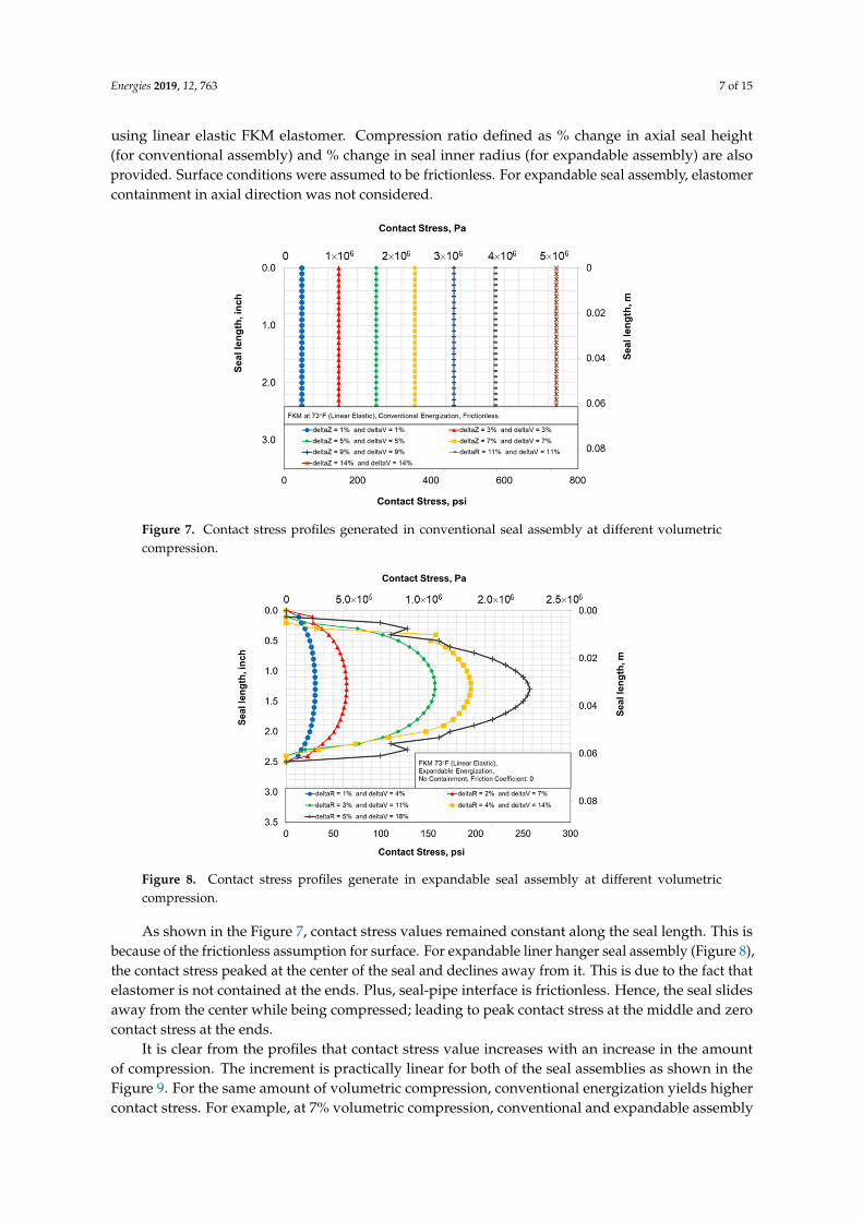
Figure 14. Contact stress profiles in expandable seal assembly for hyper-elastic FKM.
Results indicate that the contact stress profile in both assembly remains unchanged after switching to hyper-elastic material model. The contact stress values are notably higher than in the case of linear-elastic model (Figure 15). This is most likely due to the fact that in hyper-elastic model, elastomer material typically becomes stiffer at higher strain values and hence, at the same amount of deformation, higher contact stress is generated. As shown in the Figure 15, seal energization curve still remained practically linear with hyper-elastic material behavior.
Figure 13. Contact stress profiles in conventional seal assembly for hyper-elastic FKM.
Energies 2019, 12, 763 10 of 15
Energies 2019, 12, x FOR PEER REVIEW 10 of 16
Figure 13. Contact stress profiles in conventional seal assembly for hyper-elastic FKM.
Figure 14. Contact stress profiles in expandable seal assembly for hyper-elastic FKM.
Results indicate that the contact stress profile in both assembly remains unchanged after switching to hyper-elastic material model. The contact stress values are notably higher than in the case of linear-elastic model (Figure 15). This is most likely due to the fact that in hyper-elastic model, elastomer material typically becomes stiffer at higher strain values and hence, at the same amount of deformation, higher contact stress is generated. As shown in the Figure 15, seal energization curve still remained practically linear with hyper-elastic material behavior.
Figure 14. Contact stress profiles in expandable seal assembly for hyper-elastic FKM.
Results indicate that the contact stress profile in both assembly remains unchanged after switchingto hyper-elastic material model. The contact stress values are notably higher than in the case oflinear-elastic model (Figure 15). This is most likely due to the fact that in hyper-elastic model, elastomermaterial typically becomes stiffer at higher strain values and hence, at the same amount of deformation,higher contact stress is generated. As shown in the Figure 15, seal energization curve still remainedpractically linear with hyper-elastic material behavior.Energies 2019, 12, x FOR PEER REVIEW 11 of 16
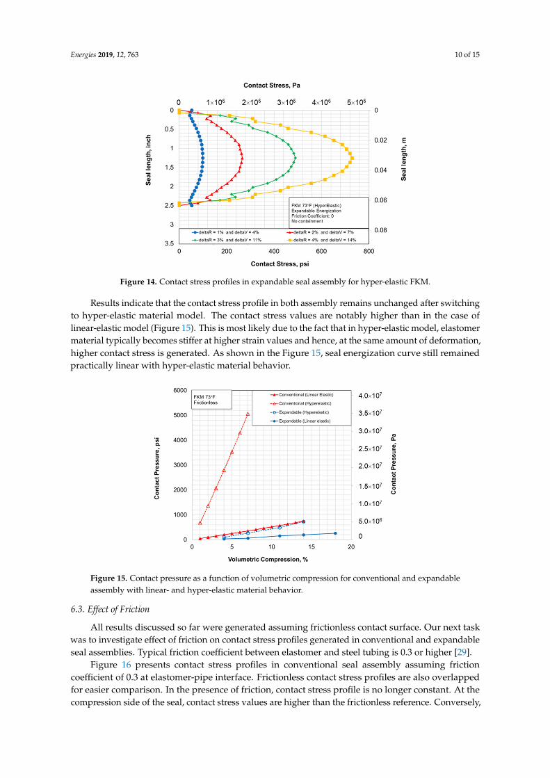
Figure 15. Contact pressure as a function of volumetric compression for conventional and expandable assembly with linear- and hyper-elastic material behavior.
6.3. Effect of Friction
All results discussed so far were generated assuming frictionless contact surface. Our next task was to investigate effect of friction on contact stress profiles generated in conventional and expandable seal assemblies. Typical friction coefficient between elastomer and steel tubing is 0.3 or higher [29].
Figure 16 presents contact stress profiles in conventional seal assembly assuming friction coefficient of 0.3 at elastomer-pipe interface. Frictionless contact stress profiles are also overlapped for easier comparison. In the presence of friction, contact stress profile is no longer constant. At the compression side of the seal, contact stress values are higher than the frictionless reference. Conversely, at the support side, contact pressure values are notably lesser than frictionless. It is clear that the compression or energization is not translated to the axially opposite end of the seal. The effect is more pronounced as volumetric compression increases. It can also be extrapolated that longer seal would also have more pronounced effect of friction. Failure to consider true frictional effect in conventional seal assembly design could be detrimental since significantly lower contact pressure values at the bottom of the seal can increase the risk of fluid penetration.
Figure 16. Effect of friction on contact stress profile in conventional seal assembly.
Figure 15. Contact pressure as a function of volumetric compression for conventional and expandableassembly with linear- and hyper-elastic material behavior.
6.3. Effect of Friction
All results discussed so far were generated assuming frictionless contact surface. Our next taskwas to investigate effect of friction on contact stress profiles generated in conventional and expandableseal assemblies. Typical friction coefficient between elastomer and steel tubing is 0.3 or higher [29].
Figure 16 presents contact stress profiles in conventional seal assembly assuming frictioncoefficient of 0.3 at elastomer-pipe interface. Frictionless contact stress profiles are also overlappedfor easier comparison. In the presence of friction, contact stress profile is no longer constant. At thecompression side of the seal, contact stress values are higher than the frictionless reference. Conversely,

Energies 2019, 12, 763 11 of 15
at the support side, contact pressure values are notably lesser than frictionless. It is clear that thecompression or energization is not translated to the axially opposite end of the seal. The effect is morepronounced as volumetric compression increases. It can also be extrapolated that longer seal wouldalso have more pronounced effect of friction. Failure to consider true frictional effect in conventionalseal assembly design could be detrimental since significantly lower contact pressure values at thebottom of the seal can increase the risk of fluid penetration.
Energies 2019, 12, x FOR PEER REVIEW 11 of 16
Figure 15. Contact pressure as a function of volumetric compression for conventional and expandable assembly with linear- and hyper-elastic material behavior.
6.3. Effect of Friction
All results discussed so far were generated assuming frictionless contact surface. Our next task was to investigate effect of friction on contact stress profiles generated in conventional and expandable seal assemblies. Typical friction coefficient between elastomer and steel tubing is 0.3 or higher [29].
Figure 16 presents contact stress profiles in conventional seal assembly assuming friction coefficient of 0.3 at elastomer-pipe interface. Frictionless contact stress profiles are also overlapped for easier comparison. In the presence of friction, contact stress profile is no longer constant. At the compression side of the seal, contact stress values are higher than the frictionless reference. Conversely, at the support side, contact pressure values are notably lesser than frictionless. It is clear that the compression or energization is not translated to the axially opposite end of the seal. The effect is more pronounced as volumetric compression increases. It can also be extrapolated that longer seal would also have more pronounced effect of friction. Failure to consider true frictional effect in conventional seal assembly design could be detrimental since significantly lower contact pressure values at the bottom of the seal can increase the risk of fluid penetration.
Figure 16. Effect of friction on contact stress profile in conventional seal assembly. Figure 16. Effect of friction on contact stress profile in conventional seal assembly.
As shown in Figure 17, unlike conventional seal assembly, expandable assembly retained theoverall shape of contact stress profile in presence of frictional sliding. However, the peak contact stressvalue increased with increase in friction coefficient from 0 to 0.3 to 0.6.
Energies 2019, 12, x FOR PEER REVIEW 12 of 16
As shown in Figure 17, unlike conventional seal assembly, expandable assembly retained the overall shape of contact stress profile in presence of frictional sliding. However, the peak contact stress value increased with increase in friction coefficient from 0 to 0.3 to 0.6.
Figure 17. Effect of friction on contact stress profile in expandable seal assembly.
7. Practical Implications
For the same volumetric compression, conventional seal assembly yields higher contact pressure than expandable seal assembly without containment. At 100% elastomer containment, contact stress profile in the expandable assembly matches with the conventional assembly. Actual expandable seal hanger assembly would almost always have elastomer containment spikes on either sides. However, to facilitate smooth running-in of the tool into the well, the spikes have to be shorter. This would provide less than 100% containment. Thus, in frictionless conditions, assuming that supporting components of either assemblies do not fail, conventional type energization will always yield higher contact pressure and should be preferred to the expandable type energization mechanism.
However, in the real field applications, contact surfaces are never frictionless. In presence of frictional stresses, contact stress profile of conventional seal assembly deviates from the uniform profile observed in frictionless condition (Figure 16). Moreover, the deviation is significantly dependent on amount of volumetric compression. Contact pressure peaks at a shorter distance from the compression side and declines rapidly towards the support side (Figure 16). Low contact pressure at the bottom would permit easy penetration of the fluid. On the other side, in expandable type energization, contact stress profile in frictional case maintains the same symmetry as the frictionless case (Figure 17). The profile becomes slightly narrower at the center but the contact pressure values at all locations are higher than the frictionless case. This improves the seal’s performance. Although, peak contact pressure values are lesser than in the conventional energization, the difference would reduce with elastomer containment spikes. Overall, in presence of friction, expandable type energization is likely to be more reliable than the conventional energization because the former yields uniformly higher contact pressure than frictionless case while also maintaining the symmetry of the contact pressure profile.
Conventional seal assembly, in addition to the compression plates on either side, has moving parts like slips for supporting bottom plate and a mechanism to exert load on the top plate. Expandable seal assembly only has non-moving containment spikes on either side of the seal (Figure 1). If elastomer containment spikes in expandable assembly fail, the seal would still maintain contact pressure as shown in Figure 8. However, if slips or compression plates in conventional assembly fail, contact pressure and consequently sealability will be completely lost.
Figure 17. Effect of friction on contact stress profile in expandable seal assembly.
7. Practical Implications
For the same volumetric compression, conventional seal assembly yields higher contact pressurethan expandable seal assembly without containment. At 100% elastomer containment, contact stressprofile in the expandable assembly matches with the conventional assembly. Actual expandable sealhanger assembly would almost always have elastomer containment spikes on either sides. However, to
Energies 2019, 12, 763 12 of 15
facilitate smooth running-in of the tool into the well, the spikes have to be shorter. This would provideless than 100% containment. Thus, in frictionless conditions, assuming that supporting components ofeither assemblies do not fail, conventional type energization will always yield higher contact pressureand should be preferred to the expandable type energization mechanism.
However, in the real field applications, contact surfaces are never frictionless. In presence offrictional stresses, contact stress profile of conventional seal assembly deviates from the uniform profileobserved in frictionless condition (Figure 16). Moreover, the deviation is significantly dependent onamount of volumetric compression. Contact pressure peaks at a shorter distance from the compressionside and declines rapidly towards the support side (Figure 16). Low contact pressure at the bottomwould permit easy penetration of the fluid. On the other side, in expandable type energization, contactstress profile in frictional case maintains the same symmetry as the frictionless case (Figure 17). Theprofile becomes slightly narrower at the center but the contact pressure values at all locations are higherthan the frictionless case. This improves the seal’s performance. Although, peak contact pressurevalues are lesser than in the conventional energization, the difference would reduce with elastomercontainment spikes. Overall, in presence of friction, expandable type energization is likely to bemore reliable than the conventional energization because the former yields uniformly higher contactpressure than frictionless case while also maintaining the symmetry of the contact pressure profile.
Conventional seal assembly, in addition to the compression plates on either side, has moving partslike slips for supporting bottom plate and a mechanism to exert load on the top plate. Expandable sealassembly only has non-moving containment spikes on either side of the seal (Figure 1). If elastomercontainment spikes in expandable assembly fail, the seal would still maintain contact pressure asshown in Figure 8. However, if slips or compression plates in conventional assembly fail, contactpressure and consequently sealability will be completely lost.
Expandable type seal energization also has additional design advantages over the conventionalassembly. In expandable assembly, the seal is energized radially. Hence, it is possible to installmultiple seal elements along the length of pipe and achieve same contact pressure in all of them. Thisredundancy further minimizes the risk of failure. In conventional assembly with multiple alternatingseal elements and compression plates, because of the frictional stress being parallel to the compressionload, it is not possible to achieve the same contact pressure in each seal. Based on the effect of frictionshown in Figure 16, it can be inferred that the peak contact pressure would subsequently decreasefrom the top seal element to the bottom seal element. This effect of friction has also been demonstratedpreviously by Ma et al. [27] in simulations of dual rubber packer equipment.
As discussed in Section 6.2, selection of material model in modelling did not impact the shape ofcontact pressure profile in either of the seal assemblies. However, hyper-elastic FKM yielded highercontact pressure values than the linear elastic FKM. This is because of the fact that FKM materialexhibited more stiffness at higher strain values. Thus, to prevent under-estimation or over-estimationof the seal’s performance, it is important to measure the elastomer material behavior over the range ofoperating strains and use correct material model in predictions.
8. Conclusions
Using three dimensional finite element models, this study presents detailed comparison of sealenergization in conventional and expandable liner hanger seal assemblies. The following are majorconclusions from this work:
• In conventional seal assembly, contact stress value decreases along the seal length from thecompression side towards the support side. In case of frictionless assumption, contact stressremains constant along the seal length.
• In expandable seal assembly, irrespective of friction coefficient, contact stress peaks at thecenter of the seal length and declines towards either sides of the axial ends. The profilebecomes progressively flatter with increase in elastomer seal containment and becomes similar toconventional seal assembly at 100% containment.

Energies 2019, 12, 763 13 of 15
• Contact pressure values increases with increase in amount of compression, i.e., %volumetriccompression. The increment is practically linear, irrespective of energization method andmaterial behavior.
• Selection of material model in modelling did not impact the shape of contact pressure profile ineither of the seal assemblies. However, hyper-elastic FKM yielded higher contact pressure valuesthan the linear elastic FKM. Therefore, it is important to measure the elastomer material behaviorover the range of operating strains and use appropriate model in predictions.
• In frictionless condition, conventional type energization will almost always provide higher peakcontact pressure values and should be preferred to the expandable type energization mechanism.
• In case of frictional contacts, expandable type energization is likely to be more reliable than theconventional energization because the former yields higher contact pressure than the frictionlesscase while also maintaining the symmetry of the contact pressure profile.
• Expandable energization is more robust to failure in supporting components than the conventionalassembly. Even if both elastomer containment spikes completely fail, the expandable seal assemblywould still maintain contact pressure.
• In expandable energization, it is possible to install multiple seal elements along the length ofpipe and achieve same contact pressure in all elements. In conventional assembly with multiplealternating seals and compression plates, peak contact pressure would subsequently decreasefrom the top seal element to the bottom seal element.
Author Contributions: H.K.P. conceptualized the idea, developed FEA models, and ran simulations. S.S. providedguidance in data analysis and paper writeup.
Funding: Work was partially funded by Bureau of Safety and Environmental Enforcement (Project No:E17PC00005).
Acknowledgments: The authors would like to extend their sincere gratitude to the University of Oklahoma forproviding necessary resources and granting the permission to publish this work.
Conflicts of Interest: The authors declare no conflict of interest.
Nomenclature
AcronymsBSEE Bureau of Safety and Environmental EnforcementEPDM Ethylene Propylene Diene MonomerFEPM Tetrafluoroethylene PropyleneFFKM PerfluorocarbonFEA Finite Element AnalysisFKM FluorocarbonHPHT High Pressure High TemperatureHNBR Hydrogenated NitrileLOWC Loss of Well ControlSymbolsαi Ogden 3rd order material constantdeltaR Percentage change in inner radius of sealdeltaV Change in seal volume due to energizationdeltaZ Percentage change in axial seal heightDi Ogden 3rd order material constantE Elastic modulus / Young’s modulusK Bulk modulusµi Ogden 3rd order material constantν Poisson’s ratioP Contact pressureV Initial seal volume∆V Change in seal volume due to energization

Energies 2019, 12, 763 14 of 15
References
1. Tu, B.; Cheng, H.L. Alternative Methodology for Elastomeric Seal RGD and Aging Testing ValidatesLong-Term Subsea Seal Performance and Integrity. In Proceedings of the Offshore Technology Conference,Houston, TX, USA, 2–5 May 2016. [CrossRef]
2. Patel, H.; Hariharan, H.; Bailey, G.; Jung, G. Advanced computer modelling for metal-to-metal seal in APIflanges. In Proceedings of the SPE Annual Technical Conference and Exhibition, Dallas, TX, USA, 24–26September 2018. [CrossRef]
3. Mullins, F. Metal-Formed Liner Hanger Avoids High-Setting-Pressure Requirements. J. Pet. Technol. 2016, 68,4–8. [CrossRef]
4. Mccormick, J.; Matice, M.; Cramp, S. Big Bore Expandable Liner Hangers for Offshore and DeepwaterApplications Reduces Cost and Increases Reliability: Global Case History. In Proceedings of the SPETT 2012Energy Conference and Exhibition, Port-of-Spain, Trinidad, 11–13 June 2012. [CrossRef]
5. Walvekar, S.; Jackson, T. Development of an Expandable Liner-Hanger System to Improve Reliability ofLiner Installations. In Proceedings of the Offshore Technology Conference, Houston, TX, USA, 30 April–3May 2007. [CrossRef]
6. Smith, P.; Williford, J. Case Histories: Liner-Completion Difficulties Resolved With Expandable Liner-TopTechnology. In Proceedings of the Canadian International Petroleum Conference, Calgary, AB, Canada,13–15 June 2006. [CrossRef]
7. Lohoefer, C.L.; Mathis, B.; Brisco, D.; Waddell, K.; Ring, L.; York, P. Expandable liner hanger providescosteffective alternative solution. In Proceedings of the IADC/SPE Drilling Conference, New Orleans, LA,USA, 23–25 February 2000. [CrossRef]
8. Van Dort, R. Metal-to-metal seals meet downhole hazard demands. J. Pet. Technol. 2009, 61, 24–26. [CrossRef]9. BSEE. QC-FIT Evaluation of Seal Assembly & Cement Failures Interim Summary of Findings; Internal QC-FIT
Report #2014-02; Bureau of Safety and Environmental Enforcement: Washington, DC, USA, 2014.10. Holand, P. Loss of Well Control Occurrence and 49 Size Estimators, Phase I and II; 51 Report #ES201471/2; Bureau
of Safety and Environmental Enforcement: Washington, DC, USA, 2017.11. Elhard, J.D.; Duguid, A.; Heinrichs, M. Research on Safety Technology Verification for Materials and Pressure
High Temperature (HPHT) Continental Shelf (OCS), High Corrosions in the U.S. Outer Material Evaluation.Technical Assessment Program Report (TAP 767AA) Prepared for Bureau of Safety and EnvironmentalEnforcement. Available online: https://www.bsee.gov/tap-technical-assessment-program/research-on-safety-technology-verification-for-materials-and (accessed on 15 September 2018).
12. Oil & Gas iQ. High Pressure High Temperate, High Costs, High Stakes? 2015. Available online: https://www.oilandgasiq.com/content-auto-download/5b04c1b543dfd0385d3c7c22 (accessed on 4 October 2018).
13. Patel, H.; Salehi, S.; Teodoriu, C.; Ahmed, R. Performance evaluation and parametric study of elastomer sealin conventional hanger assembly. J. Pet. Sci. Eng. 2019, 175, 246–254. [CrossRef]
14. Fernández, C.; Castaño, P. Compatibility Behavior of Elastomers for PCP Applications. 2016. Availableonline: https://www.onepetro.org/conferencepaper/NACE-2016-7106 (accessed on 20 October 2018).
15. Cong, C.B.; Cui, C.C.; Meng, X.Y.; Lu, S.J.; Zhou, Q. Degradation of hydrogenated nitrile-butadiene rubber inaqueous solutions of H2S or HCl. Chem. Res. Chin. Univ. 2013, 29, 806–810. [CrossRef]
16. Campion, R.P.; Thomson, B.; Harris, J.A. Elastomers for Fluid Containment in Offshore Oil and GasProduction: Guidelines and Review. Research Report (RR 320) Prepared by MERL Ltd for the Healthand Safety Executive, U.K. 2005. Available online: http://www.hse.gov.uk/research/rrpdf/rr320.pdf(accessed on 20 September 2018).
17. Bosma, M.G.R.; Cornelissen, E.K.; Schwing, A. Improved Experimental Characterization of Cement/RubberZonal Isolation Materials. In Proceedings of the SPE Asia Pacific Oil and Gas Conference and Exhibition,Brisbane, Australia, 16–18 October 2000. [CrossRef]
18. Berger, S. Experimental and Finite Element Analysis of High Pressure Packer Elements. Master’s Thesis, MAInstitute of Technology, Cambridge, MA, USA, September 2004.
19. Feng, D.; Yuan, Y.; Tan, B.; Yang, C.; Xu, G.; Wang, P. Finite Element Analysis of The Packer Rubbers onSealing Process. In Proceedings of the 2010 International Conference on Mechanic Automation and ControlEngineering, Wuhan, China, 26–28 June 2010. [CrossRef]

Energies 2019, 12, 763 15 of 15
20. Alzebdeh, K.; Pervez, T.; Qamar, S.Z. Finite Element Simulation of Compression of Elastomeric Seals inOpen Hole Liners. J. Energy Resour. Technol. 2010, 132, 031002. [CrossRef]
21. Al-Kharusi, M.S.; Qamar, S.Z.; Pervez, T.; Akhtar, M. Non-Linear Model for Evaluation of ElastomerSeals Subjected to Differential Pressure. In Proceedings of the SPE/DGS Saudi Arabia Section TechnicalSymposium and Exhibition, Al-Khobar, Saudi Arabia, 15–18 May 2011. [CrossRef]
22. Al-Hiddabi, S.A.; Pervez, T.; Qamar, S.Z.; Al-Jahwari, F.K.; Marketz, F.; Al-Houqani, S.; van de Velden, M.Analytical model of elastomer seal performance in oil wells. Appl. Math. Model. 2015, 39, 2836–2848.[CrossRef]
23. Lin, Z.C. The strength analysis and structure optimization of packer slip based on ANSYS. Appl. Mech. Mater.2013, 423, 1967–1971. [CrossRef]
24. Ma, M.; Jia, W.; Bu, Y.; Guo, S. Study on rubber seal design of a swellpacker in oil well cementing. OpenAccess Libr. J. 2014, 1, 1. [CrossRef]
25. Wang, Z.; Chen, C.; Liu, Q.; Lou, Y.; Suo, Z. Extrusion, slide, and rupture of an elastomeric seal. J. Mech. Phys.Solids 2017, 99, 289–303. [CrossRef]
26. Zhong, A.; Johnson, M.R.; Kohn, G.; Koons, B.; Saleh, M. Performance Evaluation of a Large Bore ExpandableLiner Hanger for Field Operations in the Gulf of Mexico. In Proceedings of the Offshore TechnologyConference, Houston, TX, USA, 4–7 May 2015. [CrossRef]
27. Hu, G.; Zhang, P.; Wang, G.; Zhang, M.; Li, M. The influence of rubber material on sealing performance ofpacking element in compression packer. J. Nat. Gas Sci. Eng. 2017, 38, 120–138. [CrossRef]
28. Salehi, S.; Ezeakacha, C.P.; Kwatia, G.; Ahmed, R.; Teodoriu, C. Performance verification of elastomermaterials in corrosive gas and liquid conditions. Polym. Test. 2019, 75, 48–63. [CrossRef]
29. Ma, W.; Qu, B.; Guan, F. Effect of the friction coefficient for contact pressure of packer rubber. Proc. Inst.Mech. Eng. Part C J. Mech. Eng. Sci. 2014, 228, 2881–2887. [CrossRef]
© 2019 by the authors. Licensee MDPI, Basel, Switzerland. This article is an open accessarticle distributed under the terms and conditions of the Creative Commons Attribution(CC BY) license (http://creativecommons.org/licenses/by/4.0/).