![[XLS]„œ버-2014년01월.xlsx · Web viewIBM SNSC v7.x for 1000 Switches Per Install w/3 Yr SW S&S 00AE864 00AE867 2072L2C V3700 LFF Dual Control 2072LEU V3700 LFF Expansion 2072S2C](https://static.fdocuments.net/doc/165x107/5b07b98e7f8b9a93738b5cca/xls-201401xlsxweb-viewibm-snsc-v7x-for-1000-switches-per-install.jpg)
lenovopress.com Implementing the Lenovo Storage V3700 V2 and V5030 Systems Chapter 2. Initial...
742
Last Update: 12 April 2018 Implementing the Lenovo Storage V3700 V2 and V5030 Systems Provides overview of Lenovo Storage V3700 V2, V3700 V2 XP and V5030 systems Introduces configuration setup for the storage systems Explains storage terminologies and concepts for various applications Describes troubleshooting and monitoring procedures
Transcript of lenovopress.com Implementing the Lenovo Storage V3700 V2 and V5030 Systems Chapter 2. Initial...
Last Update: 12 April 2018
Front cover
Implementing the Lenovo Storage V3700 V2 and V5030 Systems
Provides overview of Lenovo Storage V3700 V2, V3700 V2 XP and V5030 systems
Introduces configuration setup for the storage systems
Explains storage terminologies and concepts for various applications
Describes troubleshooting and monitoring procedures

2 Implementing the Lenovo Storage V3700 V2 and V5030 Systems

Implementing the Lenovo Storage V3700 V2 and V5030 Systems
12 April 2018
LP-0836-00

© Copyright Lenovo 2018. All rights reserved.Note to U.S. Government Users Restricted Rights -- Use, duplication or disclosure restricted by GSA ADP Schedule Contract
Last update 12 April 2018
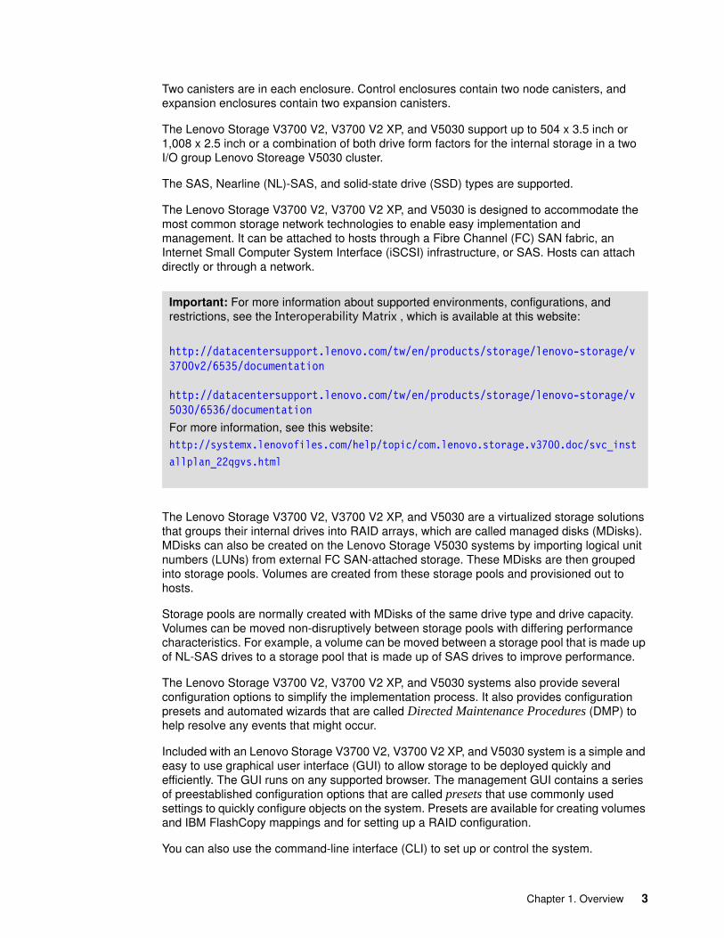
This edition applies to software version 7.6.1.3.
Note: Before using this information and the product it supports, read the information in “Notices” on page 725.

Contents
Preface . . . . . . . . . . . . . . . . . . . . . . . . . . . . . . . . . . . . . . . . . . . . . . . . . . . . . . . . . . . . . . . . . xiComments welcome. . . . . . . . . . . . . . . . . . . . . . . . . . . . . . . . . . . . . . . . . . . . . . . . . . . . . . . . xiDo you have the latest version?. . . . . . . . . . . . . . . . . . . . . . . . . . . . . . . . . . . . . . . . . . . . . . . xi
Chapter 1. Overview . . . . . . . . . . . . . . . . . . . . . . . . . . . . . . . . . . . . . . . . . . . . . . . . . . . . . . 11.1 Overview . . . . . . . . . . . . . . . . . . . . . . . . . . . . . . . . . . . . . . . . . . . . . . . . . . . . . . . . . . . . . 21.2 Terminology . . . . . . . . . . . . . . . . . . . . . . . . . . . . . . . . . . . . . . . . . . . . . . . . . . . . . . . . . . 41.3 Models. . . . . . . . . . . . . . . . . . . . . . . . . . . . . . . . . . . . . . . . . . . . . . . . . . . . . . . . . . . . . . . 51.4 Compatibility . . . . . . . . . . . . . . . . . . . . . . . . . . . . . . . . . . . . . . . . . . . . . . . . . . . . . . . . . . 81.5 Hardware platform. . . . . . . . . . . . . . . . . . . . . . . . . . . . . . . . . . . . . . . . . . . . . . . . . . . . . . 9
1.5.1 Control enclosure . . . . . . . . . . . . . . . . . . . . . . . . . . . . . . . . . . . . . . . . . . . . . . . . . 101.5.2 Lenovo Storage V3700 V2 . . . . . . . . . . . . . . . . . . . . . . . . . . . . . . . . . . . . . . . . . . 101.5.3 Lenovo Storage V3700 V2 XP . . . . . . . . . . . . . . . . . . . . . . . . . . . . . . . . . . . . . . . 111.5.4 Lenovo Storage V5030 . . . . . . . . . . . . . . . . . . . . . . . . . . . . . . . . . . . . . . . . . . . . . 121.5.5 Expansion enclosure. . . . . . . . . . . . . . . . . . . . . . . . . . . . . . . . . . . . . . . . . . . . . . . 131.5.6 Host interface cards . . . . . . . . . . . . . . . . . . . . . . . . . . . . . . . . . . . . . . . . . . . . . . . 151.5.7 Disk drive types. . . . . . . . . . . . . . . . . . . . . . . . . . . . . . . . . . . . . . . . . . . . . . . . . . . 15
1.6 Definitions of terms . . . . . . . . . . . . . . . . . . . . . . . . . . . . . . . . . . . . . . . . . . . . . . . . . . . . 161.6.1 Hosts . . . . . . . . . . . . . . . . . . . . . . . . . . . . . . . . . . . . . . . . . . . . . . . . . . . . . . . . . . . 161.6.2 Node canister . . . . . . . . . . . . . . . . . . . . . . . . . . . . . . . . . . . . . . . . . . . . . . . . . . . . 161.6.3 I/O groups . . . . . . . . . . . . . . . . . . . . . . . . . . . . . . . . . . . . . . . . . . . . . . . . . . . . . . . 171.6.4 Clustered system . . . . . . . . . . . . . . . . . . . . . . . . . . . . . . . . . . . . . . . . . . . . . . . . . 171.6.5 RAID . . . . . . . . . . . . . . . . . . . . . . . . . . . . . . . . . . . . . . . . . . . . . . . . . . . . . . . . . . . 181.6.6 Managed disks . . . . . . . . . . . . . . . . . . . . . . . . . . . . . . . . . . . . . . . . . . . . . . . . . . . 181.6.7 Quorum disks . . . . . . . . . . . . . . . . . . . . . . . . . . . . . . . . . . . . . . . . . . . . . . . . . . . . 191.6.8 Storage pools . . . . . . . . . . . . . . . . . . . . . . . . . . . . . . . . . . . . . . . . . . . . . . . . . . . . 191.6.9 Volumes . . . . . . . . . . . . . . . . . . . . . . . . . . . . . . . . . . . . . . . . . . . . . . . . . . . . . . . . 211.6.10 iSCSI. . . . . . . . . . . . . . . . . . . . . . . . . . . . . . . . . . . . . . . . . . . . . . . . . . . . . . . . . . 241.6.11 Serial-attached SCSI . . . . . . . . . . . . . . . . . . . . . . . . . . . . . . . . . . . . . . . . . . . . . 241.6.12 Fibre Channel . . . . . . . . . . . . . . . . . . . . . . . . . . . . . . . . . . . . . . . . . . . . . . . . . . . 24
1.7 Features . . . . . . . . . . . . . . . . . . . . . . . . . . . . . . . . . . . . . . . . . . . . . . . . . . . . . . . . . . . . 251.7.1 Mirrored volumes . . . . . . . . . . . . . . . . . . . . . . . . . . . . . . . . . . . . . . . . . . . . . . . . . 251.7.2 Thin Provisioning . . . . . . . . . . . . . . . . . . . . . . . . . . . . . . . . . . . . . . . . . . . . . . . . . 251.7.3 Real-time Compression. . . . . . . . . . . . . . . . . . . . . . . . . . . . . . . . . . . . . . . . . . . . . 261.7.4 Easy Tier . . . . . . . . . . . . . . . . . . . . . . . . . . . . . . . . . . . . . . . . . . . . . . . . . . . . . . . . 271.7.5 Storage Migration . . . . . . . . . . . . . . . . . . . . . . . . . . . . . . . . . . . . . . . . . . . . . . . . . 271.7.6 FlashCopy. . . . . . . . . . . . . . . . . . . . . . . . . . . . . . . . . . . . . . . . . . . . . . . . . . . . . . . 271.7.7 Remote Copy . . . . . . . . . . . . . . . . . . . . . . . . . . . . . . . . . . . . . . . . . . . . . . . . . . . . 281.7.8 IP replication . . . . . . . . . . . . . . . . . . . . . . . . . . . . . . . . . . . . . . . . . . . . . . . . . . . . . 291.7.9 External virtualization . . . . . . . . . . . . . . . . . . . . . . . . . . . . . . . . . . . . . . . . . . . . . . 291.7.10 Encryption . . . . . . . . . . . . . . . . . . . . . . . . . . . . . . . . . . . . . . . . . . . . . . . . . . . . . . 30
1.8 Problem management and support . . . . . . . . . . . . . . . . . . . . . . . . . . . . . . . . . . . . . . . . 301.8.1 Event notifications. . . . . . . . . . . . . . . . . . . . . . . . . . . . . . . . . . . . . . . . . . . . . . . . . 301.8.2 SNMP traps. . . . . . . . . . . . . . . . . . . . . . . . . . . . . . . . . . . . . . . . . . . . . . . . . . . . . . 301.8.3 Syslog messages . . . . . . . . . . . . . . . . . . . . . . . . . . . . . . . . . . . . . . . . . . . . . . . . . 301.8.4 Call Home email . . . . . . . . . . . . . . . . . . . . . . . . . . . . . . . . . . . . . . . . . . . . . . . . . . 31
1.9 More information resources . . . . . . . . . . . . . . . . . . . . . . . . . . . . . . . . . . . . . . . . . . . . . 311.9.1 Useful websites . . . . . . . . . . . . . . . . . . . . . . . . . . . . . . . . . . . . . . . . . . . . . . . . . . . 31
© Copyright Lenovo 2018. All rights reserved. iii

Chapter 2. Initial configuration . . . . . . . . . . . . . . . . . . . . . . . . . . . . . . . . . . . . . . . . . . . . 332.1 Hardware installation planning . . . . . . . . . . . . . . . . . . . . . . . . . . . . . . . . . . . . . . . . . . . 34
2.1.1 Procedure to install the SAS cables . . . . . . . . . . . . . . . . . . . . . . . . . . . . . . . . . . . 352.2 SAN configuration planning. . . . . . . . . . . . . . . . . . . . . . . . . . . . . . . . . . . . . . . . . . . . . . 382.3 FC direct-attach planning . . . . . . . . . . . . . . . . . . . . . . . . . . . . . . . . . . . . . . . . . . . . . . . 412.4 SAS direct-attach planning . . . . . . . . . . . . . . . . . . . . . . . . . . . . . . . . . . . . . . . . . . . . . . 432.5 LAN configuration planning . . . . . . . . . . . . . . . . . . . . . . . . . . . . . . . . . . . . . . . . . . . . . . 44
2.5.1 Management IP address considerations. . . . . . . . . . . . . . . . . . . . . . . . . . . . . . . . 452.5.2 Service IP address considerations . . . . . . . . . . . . . . . . . . . . . . . . . . . . . . . . . . . . 45
2.6 Host configuration planning. . . . . . . . . . . . . . . . . . . . . . . . . . . . . . . . . . . . . . . . . . . . . . 462.7 Miscellaneous configuration planning . . . . . . . . . . . . . . . . . . . . . . . . . . . . . . . . . . . . . . 482.8 System management . . . . . . . . . . . . . . . . . . . . . . . . . . . . . . . . . . . . . . . . . . . . . . . . . . 49
2.8.1 Graphical user interface (GUI) . . . . . . . . . . . . . . . . . . . . . . . . . . . . . . . . . . . . . . . 492.8.2 Command-line interface (CLI) . . . . . . . . . . . . . . . . . . . . . . . . . . . . . . . . . . . . . . . . 50
2.9 First-time setup . . . . . . . . . . . . . . . . . . . . . . . . . . . . . . . . . . . . . . . . . . . . . . . . . . . . . . . 512.10 Initial configuration . . . . . . . . . . . . . . . . . . . . . . . . . . . . . . . . . . . . . . . . . . . . . . . . . . . 56
2.10.1 Configuring storage. . . . . . . . . . . . . . . . . . . . . . . . . . . . . . . . . . . . . . . . . . . . . . . 672.10.2 Adding enclosures after the initial configuration . . . . . . . . . . . . . . . . . . . . . . . . . 682.10.3 Configuring Call Home, email alert, and inventory . . . . . . . . . . . . . . . . . . . . . . . 752.10.4 Service Assistant Tool . . . . . . . . . . . . . . . . . . . . . . . . . . . . . . . . . . . . . . . . . . . . 77
Chapter 3. Graphical user interface overview . . . . . . . . . . . . . . . . . . . . . . . . . . . . . . . . 813.1 Overview of IBM Spectrum Virtualize management software . . . . . . . . . . . . . . . . . . . . 82
3.1.1 Access to the storage management software . . . . . . . . . . . . . . . . . . . . . . . . . . . . 823.1.2 System pane layout . . . . . . . . . . . . . . . . . . . . . . . . . . . . . . . . . . . . . . . . . . . . . . . 853.1.3 Navigation . . . . . . . . . . . . . . . . . . . . . . . . . . . . . . . . . . . . . . . . . . . . . . . . . . . . . . . 863.1.4 Multiple selection . . . . . . . . . . . . . . . . . . . . . . . . . . . . . . . . . . . . . . . . . . . . . . . . . 873.1.5 Status indicators area . . . . . . . . . . . . . . . . . . . . . . . . . . . . . . . . . . . . . . . . . . . . . . 88
3.2 Overview pane . . . . . . . . . . . . . . . . . . . . . . . . . . . . . . . . . . . . . . . . . . . . . . . . . . . . . . . 913.3 Monitoring menu . . . . . . . . . . . . . . . . . . . . . . . . . . . . . . . . . . . . . . . . . . . . . . . . . . . . . . 91
3.3.1 System overview. . . . . . . . . . . . . . . . . . . . . . . . . . . . . . . . . . . . . . . . . . . . . . . . . . 923.3.2 System details. . . . . . . . . . . . . . . . . . . . . . . . . . . . . . . . . . . . . . . . . . . . . . . . . . . . 953.3.3 Events . . . . . . . . . . . . . . . . . . . . . . . . . . . . . . . . . . . . . . . . . . . . . . . . . . . . . . . . . . 973.3.4 Performance . . . . . . . . . . . . . . . . . . . . . . . . . . . . . . . . . . . . . . . . . . . . . . . . . . . . . 97
3.4 Pools menu . . . . . . . . . . . . . . . . . . . . . . . . . . . . . . . . . . . . . . . . . . . . . . . . . . . . . . . . . . 983.4.1 Pools . . . . . . . . . . . . . . . . . . . . . . . . . . . . . . . . . . . . . . . . . . . . . . . . . . . . . . . . . . 1003.4.2 Child pools . . . . . . . . . . . . . . . . . . . . . . . . . . . . . . . . . . . . . . . . . . . . . . . . . . . . . 1023.4.3 Volumes by pool . . . . . . . . . . . . . . . . . . . . . . . . . . . . . . . . . . . . . . . . . . . . . . . . . 1033.4.4 Internal storage . . . . . . . . . . . . . . . . . . . . . . . . . . . . . . . . . . . . . . . . . . . . . . . . . . 1053.4.5 External storage . . . . . . . . . . . . . . . . . . . . . . . . . . . . . . . . . . . . . . . . . . . . . . . . . 1053.4.6 MDisks by pools . . . . . . . . . . . . . . . . . . . . . . . . . . . . . . . . . . . . . . . . . . . . . . . . . 1073.4.7 System migration . . . . . . . . . . . . . . . . . . . . . . . . . . . . . . . . . . . . . . . . . . . . . . . . 107
3.5 Volumes menu . . . . . . . . . . . . . . . . . . . . . . . . . . . . . . . . . . . . . . . . . . . . . . . . . . . . . . 1083.5.1 All volumes . . . . . . . . . . . . . . . . . . . . . . . . . . . . . . . . . . . . . . . . . . . . . . . . . . . . . 1103.5.2 Volumes by pool . . . . . . . . . . . . . . . . . . . . . . . . . . . . . . . . . . . . . . . . . . . . . . . . . 1123.5.3 Volumes by host . . . . . . . . . . . . . . . . . . . . . . . . . . . . . . . . . . . . . . . . . . . . . . . . . 112
3.6 Hosts menu . . . . . . . . . . . . . . . . . . . . . . . . . . . . . . . . . . . . . . . . . . . . . . . . . . . . . . . . . 1133.6.1 Hosts . . . . . . . . . . . . . . . . . . . . . . . . . . . . . . . . . . . . . . . . . . . . . . . . . . . . . . . . . . 1133.6.2 Ports by host . . . . . . . . . . . . . . . . . . . . . . . . . . . . . . . . . . . . . . . . . . . . . . . . . . . . 1153.6.3 Host mappings . . . . . . . . . . . . . . . . . . . . . . . . . . . . . . . . . . . . . . . . . . . . . . . . . . 1163.6.4 Volumes by host . . . . . . . . . . . . . . . . . . . . . . . . . . . . . . . . . . . . . . . . . . . . . . . . . 117
3.7 Copy services . . . . . . . . . . . . . . . . . . . . . . . . . . . . . . . . . . . . . . . . . . . . . . . . . . . . . . . 1173.7.1 FlashCopy. . . . . . . . . . . . . . . . . . . . . . . . . . . . . . . . . . . . . . . . . . . . . . . . . . . . . . 117
iv Implementing the Lenovo Storage V3700 V2 and V5030 Systems

3.7.2 Consistency group . . . . . . . . . . . . . . . . . . . . . . . . . . . . . . . . . . . . . . . . . . . . . . . 1193.7.3 FlashCopy mappings . . . . . . . . . . . . . . . . . . . . . . . . . . . . . . . . . . . . . . . . . . . . . 1213.7.4 Remote copy. . . . . . . . . . . . . . . . . . . . . . . . . . . . . . . . . . . . . . . . . . . . . . . . . . . . 1223.7.5 Partnerships . . . . . . . . . . . . . . . . . . . . . . . . . . . . . . . . . . . . . . . . . . . . . . . . . . . . 123
3.8 Access menu. . . . . . . . . . . . . . . . . . . . . . . . . . . . . . . . . . . . . . . . . . . . . . . . . . . . . . . . 1243.8.1 Users. . . . . . . . . . . . . . . . . . . . . . . . . . . . . . . . . . . . . . . . . . . . . . . . . . . . . . . . . . 1253.8.2 Audit Log option . . . . . . . . . . . . . . . . . . . . . . . . . . . . . . . . . . . . . . . . . . . . . . . . . 126
3.9 Settings menu . . . . . . . . . . . . . . . . . . . . . . . . . . . . . . . . . . . . . . . . . . . . . . . . . . . . . . . 1283.9.1 Notifications . . . . . . . . . . . . . . . . . . . . . . . . . . . . . . . . . . . . . . . . . . . . . . . . . . . . 1283.9.2 Network. . . . . . . . . . . . . . . . . . . . . . . . . . . . . . . . . . . . . . . . . . . . . . . . . . . . . . . . 1293.9.3 Security . . . . . . . . . . . . . . . . . . . . . . . . . . . . . . . . . . . . . . . . . . . . . . . . . . . . . . . . 1303.9.4 System . . . . . . . . . . . . . . . . . . . . . . . . . . . . . . . . . . . . . . . . . . . . . . . . . . . . . . . . 1333.9.5 Support . . . . . . . . . . . . . . . . . . . . . . . . . . . . . . . . . . . . . . . . . . . . . . . . . . . . . . . . 1353.9.6 GUI preferences . . . . . . . . . . . . . . . . . . . . . . . . . . . . . . . . . . . . . . . . . . . . . . . . . 136
Chapter 4. Host configuration . . . . . . . . . . . . . . . . . . . . . . . . . . . . . . . . . . . . . . . . . . . . 1394.1 Host attachment overview. . . . . . . . . . . . . . . . . . . . . . . . . . . . . . . . . . . . . . . . . . . . . . 1404.2 Planning for direct-attached hosts. . . . . . . . . . . . . . . . . . . . . . . . . . . . . . . . . . . . . . . . 141
4.2.1 Fibre Channel direct attachment to host systems. . . . . . . . . . . . . . . . . . . . . . . . 1414.2.2 FC direct attachment between nodes . . . . . . . . . . . . . . . . . . . . . . . . . . . . . . . . . 141
4.3 Preparing the host operating system . . . . . . . . . . . . . . . . . . . . . . . . . . . . . . . . . . . . . 1424.3.1 Windows 2008 R2 and 2012 R2: Preparing for Fibre Channel attachment . . . . 1424.3.2 Windows 2008 R2 and Windows 2012 R2: Preparing for iSCSI attachment . . . 1484.3.3 Windows 2012 R2: Preparing for SAS attachment . . . . . . . . . . . . . . . . . . . . . . . 1544.3.4 VMware ESXi: Preparing for Fibre Channel attachment. . . . . . . . . . . . . . . . . . . 1554.3.5 VMware ESXi: Preparing for iSCSI attachment . . . . . . . . . . . . . . . . . . . . . . . . . 1584.3.6 VMware ESXi: Preparing for SAS attachment . . . . . . . . . . . . . . . . . . . . . . . . . . 167
4.4 Creating hosts by using the GUI . . . . . . . . . . . . . . . . . . . . . . . . . . . . . . . . . . . . . . . . . 1684.4.1 Creating Fibre Channel hosts . . . . . . . . . . . . . . . . . . . . . . . . . . . . . . . . . . . . . . . 1704.4.2 Configuring the Storage Systems for FC connectivity. . . . . . . . . . . . . . . . . . . . . 1754.4.3 Creating iSCSI hosts. . . . . . . . . . . . . . . . . . . . . . . . . . . . . . . . . . . . . . . . . . . . . . 1784.4.4 Configuring the Storage Systems for iSCSI host connectivity . . . . . . . . . . . . . . 1804.4.5 Creating SAS hosts. . . . . . . . . . . . . . . . . . . . . . . . . . . . . . . . . . . . . . . . . . . . . . . 185
Chapter 5. Volume configuration . . . . . . . . . . . . . . . . . . . . . . . . . . . . . . . . . . . . . . . . . . 1895.1 Creating volumes . . . . . . . . . . . . . . . . . . . . . . . . . . . . . . . . . . . . . . . . . . . . . . . . . . . . 1905.2 Creating volumes by using the Quick Volume Creation option . . . . . . . . . . . . . . . . . . 193
5.2.1 Creating basic volumes by using the Quick Volume Creation option . . . . . . . . . 1935.2.2 Creating mirrored volumes by using Quick Volume Creation option. . . . . . . . . . 196
5.3 Mapping a volume to the host . . . . . . . . . . . . . . . . . . . . . . . . . . . . . . . . . . . . . . . . . . . 2005.4 Creating custom volumes by using the Advanced option . . . . . . . . . . . . . . . . . . . . . . 202
5.4.1 Creating a custom thin-provisioned volume . . . . . . . . . . . . . . . . . . . . . . . . . . . . 2025.5 Using Real-time Compression Software . . . . . . . . . . . . . . . . . . . . . . . . . . . . . . . . . . . 205
5.5.1 RtC overview. . . . . . . . . . . . . . . . . . . . . . . . . . . . . . . . . . . . . . . . . . . . . . . . . . . . 2065.5.2 Common use cases . . . . . . . . . . . . . . . . . . . . . . . . . . . . . . . . . . . . . . . . . . . . . . 2065.5.3 Real-time Compression concepts . . . . . . . . . . . . . . . . . . . . . . . . . . . . . . . . . . . . 2075.5.4 Random Access Compression Engine . . . . . . . . . . . . . . . . . . . . . . . . . . . . . . . . 2085.5.5 RACE technology in the Lenovo Storage V-series software stack . . . . . . . . . . . 2135.5.6 Write request data flow . . . . . . . . . . . . . . . . . . . . . . . . . . . . . . . . . . . . . . . . . . . . 2145.5.7 Read request data flow . . . . . . . . . . . . . . . . . . . . . . . . . . . . . . . . . . . . . . . . . . . . 2145.5.8 Compression of existing data . . . . . . . . . . . . . . . . . . . . . . . . . . . . . . . . . . . . . . . 2155.5.9 Creating custom compressed volumes. . . . . . . . . . . . . . . . . . . . . . . . . . . . . . . . 2165.5.10 Custom mirrored volumes. . . . . . . . . . . . . . . . . . . . . . . . . . . . . . . . . . . . . . . . . 217
Contents v

Chapter 6. Storage migration . . . . . . . . . . . . . . . . . . . . . . . . . . . . . . . . . . . . . . . . . . . . . 2216.1 Interoperability and compatibility . . . . . . . . . . . . . . . . . . . . . . . . . . . . . . . . . . . . . . . . . 2226.2 Storage migration wizard . . . . . . . . . . . . . . . . . . . . . . . . . . . . . . . . . . . . . . . . . . . . . . 222
6.2.1 External virtualization capability . . . . . . . . . . . . . . . . . . . . . . . . . . . . . . . . . . . . . 2226.2.2 Model and adapter card considerations . . . . . . . . . . . . . . . . . . . . . . . . . . . . . . . 2226.2.3 Overview of the storage migration wizard . . . . . . . . . . . . . . . . . . . . . . . . . . . . . . 2236.2.4 Storage migration wizard tasks. . . . . . . . . . . . . . . . . . . . . . . . . . . . . . . . . . . . . . 224
Chapter 7. Storage pools . . . . . . . . . . . . . . . . . . . . . . . . . . . . . . . . . . . . . . . . . . . . . . . . 2537.1 Working with internal drives . . . . . . . . . . . . . . . . . . . . . . . . . . . . . . . . . . . . . . . . . . . . 254
7.1.1 Internal Storage window . . . . . . . . . . . . . . . . . . . . . . . . . . . . . . . . . . . . . . . . . . . 2557.1.2 Actions on internal drives . . . . . . . . . . . . . . . . . . . . . . . . . . . . . . . . . . . . . . . . . . 257
7.2 Configuring internal storage . . . . . . . . . . . . . . . . . . . . . . . . . . . . . . . . . . . . . . . . . . . . 2677.2.1 RAID configuration . . . . . . . . . . . . . . . . . . . . . . . . . . . . . . . . . . . . . . . . . . . . . . . 2697.2.2 Distributed RAID . . . . . . . . . . . . . . . . . . . . . . . . . . . . . . . . . . . . . . . . . . . . . . . . . 2707.2.3 RAID configuration presets . . . . . . . . . . . . . . . . . . . . . . . . . . . . . . . . . . . . . . . . . 2737.2.4 Customizing storage configuration . . . . . . . . . . . . . . . . . . . . . . . . . . . . . . . . . . . 2757.2.5 Creating a pool . . . . . . . . . . . . . . . . . . . . . . . . . . . . . . . . . . . . . . . . . . . . . . . . . . 2767.2.6 Add storage to a pool . . . . . . . . . . . . . . . . . . . . . . . . . . . . . . . . . . . . . . . . . . . . . 2787.2.7 Assign storage to a pool . . . . . . . . . . . . . . . . . . . . . . . . . . . . . . . . . . . . . . . . . . . 2867.2.8 More actions on MDisks . . . . . . . . . . . . . . . . . . . . . . . . . . . . . . . . . . . . . . . . . . . 289
7.3 Working with storage pools . . . . . . . . . . . . . . . . . . . . . . . . . . . . . . . . . . . . . . . . . . . . . 2937.3.1 Create Pool option . . . . . . . . . . . . . . . . . . . . . . . . . . . . . . . . . . . . . . . . . . . . . . . 2957.3.2 Actions on storage pools. . . . . . . . . . . . . . . . . . . . . . . . . . . . . . . . . . . . . . . . . . . 297
7.4 Working with MDisks on external storage . . . . . . . . . . . . . . . . . . . . . . . . . . . . . . . . . . 303
Chapter 8. Advanced host and volume administration . . . . . . . . . . . . . . . . . . . . . . . . 3058.1 Advanced host administration . . . . . . . . . . . . . . . . . . . . . . . . . . . . . . . . . . . . . . . . . . . 306
8.1.1 Modifying volume mappings . . . . . . . . . . . . . . . . . . . . . . . . . . . . . . . . . . . . . . . . 3088.1.2 Unmapping volumes from a host . . . . . . . . . . . . . . . . . . . . . . . . . . . . . . . . . . . . 3118.1.3 Renaming a host . . . . . . . . . . . . . . . . . . . . . . . . . . . . . . . . . . . . . . . . . . . . . . . . . 3148.1.4 Removing a host . . . . . . . . . . . . . . . . . . . . . . . . . . . . . . . . . . . . . . . . . . . . . . . . . 3158.1.5 Host properties . . . . . . . . . . . . . . . . . . . . . . . . . . . . . . . . . . . . . . . . . . . . . . . . . . 316
8.2 Adding and deleting host ports . . . . . . . . . . . . . . . . . . . . . . . . . . . . . . . . . . . . . . . . . . 3208.2.1 Adding a host port . . . . . . . . . . . . . . . . . . . . . . . . . . . . . . . . . . . . . . . . . . . . . . . . 3218.2.2 Adding a Fibre Channel port . . . . . . . . . . . . . . . . . . . . . . . . . . . . . . . . . . . . . . . . 3228.2.3 Adding a SAS host port. . . . . . . . . . . . . . . . . . . . . . . . . . . . . . . . . . . . . . . . . . . . 3238.2.4 Adding an iSCSI host port. . . . . . . . . . . . . . . . . . . . . . . . . . . . . . . . . . . . . . . . . . 3248.2.5 Deleting a host port . . . . . . . . . . . . . . . . . . . . . . . . . . . . . . . . . . . . . . . . . . . . . . . 325
8.3 Host mappings overview . . . . . . . . . . . . . . . . . . . . . . . . . . . . . . . . . . . . . . . . . . . . . . . 3268.3.1 Unmap Volumes . . . . . . . . . . . . . . . . . . . . . . . . . . . . . . . . . . . . . . . . . . . . . . . . . 3288.3.2 Properties (Host) . . . . . . . . . . . . . . . . . . . . . . . . . . . . . . . . . . . . . . . . . . . . . . . . . 3288.3.3 Properties (Volume) . . . . . . . . . . . . . . . . . . . . . . . . . . . . . . . . . . . . . . . . . . . . . . 328
8.4 Advanced volume administration . . . . . . . . . . . . . . . . . . . . . . . . . . . . . . . . . . . . . . . . 3288.4.1 Advanced volume functions . . . . . . . . . . . . . . . . . . . . . . . . . . . . . . . . . . . . . . . . 3298.4.2 Mapping a volume to a host . . . . . . . . . . . . . . . . . . . . . . . . . . . . . . . . . . . . . . . . 3318.4.3 Unmapping volumes from all hosts . . . . . . . . . . . . . . . . . . . . . . . . . . . . . . . . . . . 3328.4.4 Viewing which host is mapped to a volume . . . . . . . . . . . . . . . . . . . . . . . . . . . . 3338.4.5 Renaming a volume . . . . . . . . . . . . . . . . . . . . . . . . . . . . . . . . . . . . . . . . . . . . . . 3338.4.6 Shrinking a volume . . . . . . . . . . . . . . . . . . . . . . . . . . . . . . . . . . . . . . . . . . . . . . . 3348.4.7 Expanding a volume . . . . . . . . . . . . . . . . . . . . . . . . . . . . . . . . . . . . . . . . . . . . . . 3358.4.8 Migrating a volume to another storage pool . . . . . . . . . . . . . . . . . . . . . . . . . . . . 3358.4.9 Exporting to an image mode volume. . . . . . . . . . . . . . . . . . . . . . . . . . . . . . . . . . 3388.4.10 Deleting a volume . . . . . . . . . . . . . . . . . . . . . . . . . . . . . . . . . . . . . . . . . . . . . . . 340
vi Implementing the Lenovo Storage V3700 V2 and V5030 Systems

8.4.11 Duplicating a volume. . . . . . . . . . . . . . . . . . . . . . . . . . . . . . . . . . . . . . . . . . . . . 3408.4.12 Adding a volume copy. . . . . . . . . . . . . . . . . . . . . . . . . . . . . . . . . . . . . . . . . . . . 342
8.5 Volume properties and volume copy properties . . . . . . . . . . . . . . . . . . . . . . . . . . . . . 3448.6 Advanced volume copy functions . . . . . . . . . . . . . . . . . . . . . . . . . . . . . . . . . . . . . . . . 347
8.6.1 Volume copy: Make Primary . . . . . . . . . . . . . . . . . . . . . . . . . . . . . . . . . . . . . . . . 3488.6.2 Splitting into a new volume . . . . . . . . . . . . . . . . . . . . . . . . . . . . . . . . . . . . . . . . . 3498.6.3 Validate Volume Copies option. . . . . . . . . . . . . . . . . . . . . . . . . . . . . . . . . . . . . . 3508.6.4 Delete volume copy option . . . . . . . . . . . . . . . . . . . . . . . . . . . . . . . . . . . . . . . . . 3538.6.5 Migrating volumes by using the volume copy features . . . . . . . . . . . . . . . . . . . . 354
8.7 Volumes by storage pool. . . . . . . . . . . . . . . . . . . . . . . . . . . . . . . . . . . . . . . . . . . . . . . 3558.8 Volumes by host . . . . . . . . . . . . . . . . . . . . . . . . . . . . . . . . . . . . . . . . . . . . . . . . . . . . . 356
Chapter 9. Easy Tier . . . . . . . . . . . . . . . . . . . . . . . . . . . . . . . . . . . . . . . . . . . . . . . . . . . . 3599.1 Generations of Easy Tier . . . . . . . . . . . . . . . . . . . . . . . . . . . . . . . . . . . . . . . . . . . . . . 3609.2 New features in Easy Tier 3 . . . . . . . . . . . . . . . . . . . . . . . . . . . . . . . . . . . . . . . . . . . . 3609.3 Easy Tier overview . . . . . . . . . . . . . . . . . . . . . . . . . . . . . . . . . . . . . . . . . . . . . . . . . . . 361
9.3.1 Tiered storage pools . . . . . . . . . . . . . . . . . . . . . . . . . . . . . . . . . . . . . . . . . . . . . . 3629.4 Easy Tier process . . . . . . . . . . . . . . . . . . . . . . . . . . . . . . . . . . . . . . . . . . . . . . . . . . . . 365
9.4.1 I/O Monitoring . . . . . . . . . . . . . . . . . . . . . . . . . . . . . . . . . . . . . . . . . . . . . . . . . . . 3659.4.2 Data Placement Advisor . . . . . . . . . . . . . . . . . . . . . . . . . . . . . . . . . . . . . . . . . . . 3659.4.3 Data Migration Planner . . . . . . . . . . . . . . . . . . . . . . . . . . . . . . . . . . . . . . . . . . . . 3659.4.4 Data Migrator . . . . . . . . . . . . . . . . . . . . . . . . . . . . . . . . . . . . . . . . . . . . . . . . . . . 3659.4.5 Easy Tier accelerated mode . . . . . . . . . . . . . . . . . . . . . . . . . . . . . . . . . . . . . . . . 3669.4.6 Easy Tier operating modes . . . . . . . . . . . . . . . . . . . . . . . . . . . . . . . . . . . . . . . . . 3679.4.7 Easy Tier status . . . . . . . . . . . . . . . . . . . . . . . . . . . . . . . . . . . . . . . . . . . . . . . . . 3689.4.8 Storage Pool Balancing . . . . . . . . . . . . . . . . . . . . . . . . . . . . . . . . . . . . . . . . . . . 3689.4.9 Easy Tier rules . . . . . . . . . . . . . . . . . . . . . . . . . . . . . . . . . . . . . . . . . . . . . . . . . . 369
9.5 Easy Tier configuration by using the GUI . . . . . . . . . . . . . . . . . . . . . . . . . . . . . . . . . . 3719.5.1 Creating multi-tiered pools: Enabling Easy Tier . . . . . . . . . . . . . . . . . . . . . . . . . 3719.5.2 Downloading Easy Tier I/O measurements. . . . . . . . . . . . . . . . . . . . . . . . . . . . . 379
9.6 Easy Tier configuration by using the command-line interface. . . . . . . . . . . . . . . . . . . 3819.6.1 Enabling Easy Tier measured mode. . . . . . . . . . . . . . . . . . . . . . . . . . . . . . . . . . 3829.6.2 Enabling or disabling Easy Tier on single volumes. . . . . . . . . . . . . . . . . . . . . . . 385
9.7 IBM Storage Tier Advisor Tool . . . . . . . . . . . . . . . . . . . . . . . . . . . . . . . . . . . . . . . . . . 3889.7.1 Processing heat log files . . . . . . . . . . . . . . . . . . . . . . . . . . . . . . . . . . . . . . . . . . . 3889.7.2 Storage Tier Advisor Tool reports . . . . . . . . . . . . . . . . . . . . . . . . . . . . . . . . . . . . 389
Chapter 10. Copy services . . . . . . . . . . . . . . . . . . . . . . . . . . . . . . . . . . . . . . . . . . . . . . . 39310.1 FlashCopy . . . . . . . . . . . . . . . . . . . . . . . . . . . . . . . . . . . . . . . . . . . . . . . . . . . . . . . . . 394
10.1.1 Business requirements for FlashCopy . . . . . . . . . . . . . . . . . . . . . . . . . . . . . . . 39410.1.2 FlashCopy functional overview . . . . . . . . . . . . . . . . . . . . . . . . . . . . . . . . . . . . . 39510.1.3 Planning for FlashCopy. . . . . . . . . . . . . . . . . . . . . . . . . . . . . . . . . . . . . . . . . . . 40410.1.4 Managing FlashCopy by using the GUI . . . . . . . . . . . . . . . . . . . . . . . . . . . . . . 40610.1.5 Managing FlashCopy mappings . . . . . . . . . . . . . . . . . . . . . . . . . . . . . . . . . . . . 41410.1.6 Managing a FlashCopy consistency group . . . . . . . . . . . . . . . . . . . . . . . . . . . . 442
10.2 Remote Copy . . . . . . . . . . . . . . . . . . . . . . . . . . . . . . . . . . . . . . . . . . . . . . . . . . . . . . 45310.2.1 Remote Copy concepts. . . . . . . . . . . . . . . . . . . . . . . . . . . . . . . . . . . . . . . . . . . 45410.2.2 Global Mirror with Change Volumes . . . . . . . . . . . . . . . . . . . . . . . . . . . . . . . . . 46110.2.3 Remote Copy planning . . . . . . . . . . . . . . . . . . . . . . . . . . . . . . . . . . . . . . . . . . . 466
10.3 Troubleshooting Remote Copy . . . . . . . . . . . . . . . . . . . . . . . . . . . . . . . . . . . . . . . . . 46910.3.1 1920 error . . . . . . . . . . . . . . . . . . . . . . . . . . . . . . . . . . . . . . . . . . . . . . . . . . . . . 46910.3.2 1720 error . . . . . . . . . . . . . . . . . . . . . . . . . . . . . . . . . . . . . . . . . . . . . . . . . . . . . 472
10.4 Managing Remote Copy by using the GUI . . . . . . . . . . . . . . . . . . . . . . . . . . . . . . . . 473
Contents vii

10.4.1 Managing cluster partnerships . . . . . . . . . . . . . . . . . . . . . . . . . . . . . . . . . . . . . 47310.4.2 Managing stand-alone Remote Copy relationships . . . . . . . . . . . . . . . . . . . . . 48110.4.3 Managing a Remote Copy consistency group . . . . . . . . . . . . . . . . . . . . . . . . . 494
10.5 HyperSwap . . . . . . . . . . . . . . . . . . . . . . . . . . . . . . . . . . . . . . . . . . . . . . . . . . . . . . . . 51110.5.1 Introduction to HyperSwap volumes . . . . . . . . . . . . . . . . . . . . . . . . . . . . . . . . . 51210.5.2 Failure scenarios. . . . . . . . . . . . . . . . . . . . . . . . . . . . . . . . . . . . . . . . . . . . . . . . 51910.5.3 Current HyperSwap limitations . . . . . . . . . . . . . . . . . . . . . . . . . . . . . . . . . . . . . 52210.5.4 Configuring HyperSwap . . . . . . . . . . . . . . . . . . . . . . . . . . . . . . . . . . . . . . . . . . 52310.5.5 Consistency groups for HyperSwap volumes . . . . . . . . . . . . . . . . . . . . . . . . . . 53810.5.6 FlashCopy operations and HyperSwap volumes . . . . . . . . . . . . . . . . . . . . . . . 54310.5.7 Data migration to HyperSwap volumes. . . . . . . . . . . . . . . . . . . . . . . . . . . . . . . 547
Chapter 11. External storage virtualization . . . . . . . . . . . . . . . . . . . . . . . . . . . . . . . . . 54911.1 Planning for external storage virtualization . . . . . . . . . . . . . . . . . . . . . . . . . . . . . . . . 550
11.1.1 License for external storage virtualization. . . . . . . . . . . . . . . . . . . . . . . . . . . . . 55011.1.2 SAN configuration planning . . . . . . . . . . . . . . . . . . . . . . . . . . . . . . . . . . . . . . . 55011.1.3 External storage configuration planning . . . . . . . . . . . . . . . . . . . . . . . . . . . . . . 55211.1.4 Guidelines for virtualizing external storage . . . . . . . . . . . . . . . . . . . . . . . . . . . . 552
11.2 Working with external storage. . . . . . . . . . . . . . . . . . . . . . . . . . . . . . . . . . . . . . . . . . 55311.2.1 Adding external storage . . . . . . . . . . . . . . . . . . . . . . . . . . . . . . . . . . . . . . . . . . 55311.2.2 Importing image mode volumes . . . . . . . . . . . . . . . . . . . . . . . . . . . . . . . . . . . . 55811.2.3 Managing external storage . . . . . . . . . . . . . . . . . . . . . . . . . . . . . . . . . . . . . . . . 56711.2.4 Removing external storage . . . . . . . . . . . . . . . . . . . . . . . . . . . . . . . . . . . . . . . . 573
Chapter 12. RAS, monitoring, and troubleshooting. . . . . . . . . . . . . . . . . . . . . . . . . . . 57512.1 Reliability, availability, and serviceability features. . . . . . . . . . . . . . . . . . . . . . . . . . . 57612.2 System components . . . . . . . . . . . . . . . . . . . . . . . . . . . . . . . . . . . . . . . . . . . . . . . . . 577
12.2.1 Enclosure midplane . . . . . . . . . . . . . . . . . . . . . . . . . . . . . . . . . . . . . . . . . . . . . 57712.2.2 Node canisters . . . . . . . . . . . . . . . . . . . . . . . . . . . . . . . . . . . . . . . . . . . . . . . . . 57712.2.3 Expansion canisters . . . . . . . . . . . . . . . . . . . . . . . . . . . . . . . . . . . . . . . . . . . . . 58612.2.4 Disk subsystem. . . . . . . . . . . . . . . . . . . . . . . . . . . . . . . . . . . . . . . . . . . . . . . . . 58812.2.5 Power supply units . . . . . . . . . . . . . . . . . . . . . . . . . . . . . . . . . . . . . . . . . . . . . . 592
12.3 Configuration backup . . . . . . . . . . . . . . . . . . . . . . . . . . . . . . . . . . . . . . . . . . . . . . . . 59412.3.1 Generating a manual configuration backup by using the CLI . . . . . . . . . . . . . . 59412.3.2 Downloading a configuration backup by using the GUI . . . . . . . . . . . . . . . . . . 595
12.4 System update . . . . . . . . . . . . . . . . . . . . . . . . . . . . . . . . . . . . . . . . . . . . . . . . . . . . . 59712.4.1 Updating node canister software . . . . . . . . . . . . . . . . . . . . . . . . . . . . . . . . . . . 59712.4.2 Updating the drive firmware . . . . . . . . . . . . . . . . . . . . . . . . . . . . . . . . . . . . . . . 611
12.5 Monitoring . . . . . . . . . . . . . . . . . . . . . . . . . . . . . . . . . . . . . . . . . . . . . . . . . . . . . . . . . 61612.5.1 Email notifications and Call Home . . . . . . . . . . . . . . . . . . . . . . . . . . . . . . . . . . 616
12.6 Audit log . . . . . . . . . . . . . . . . . . . . . . . . . . . . . . . . . . . . . . . . . . . . . . . . . . . . . . . . . . 62012.7 Event log . . . . . . . . . . . . . . . . . . . . . . . . . . . . . . . . . . . . . . . . . . . . . . . . . . . . . . . . . . 622
12.7.1 Managing the event log. . . . . . . . . . . . . . . . . . . . . . . . . . . . . . . . . . . . . . . . . . . 62312.7.2 Alert handling and recommended actions. . . . . . . . . . . . . . . . . . . . . . . . . . . . . 626
12.8 Collecting support information. . . . . . . . . . . . . . . . . . . . . . . . . . . . . . . . . . . . . . . . . . 63012.8.1 Collecting support information by using the GUI. . . . . . . . . . . . . . . . . . . . . . . . 63012.8.2 Collecting support information by using the SAT . . . . . . . . . . . . . . . . . . . . . . . 632
12.9 Powering off the system and shutting down the infrastructure . . . . . . . . . . . . . . . . . 63512.9.1 Powering off . . . . . . . . . . . . . . . . . . . . . . . . . . . . . . . . . . . . . . . . . . . . . . . . . . . 63512.9.2 Shutting down and starting up the infrastructure. . . . . . . . . . . . . . . . . . . . . . . . 639
Chapter 13. Encryption . . . . . . . . . . . . . . . . . . . . . . . . . . . . . . . . . . . . . . . . . . . . . . . . . . 64113.1 Introducing encryption. . . . . . . . . . . . . . . . . . . . . . . . . . . . . . . . . . . . . . . . . . . . . . . . 64213.2 Defining encryption of data at rest . . . . . . . . . . . . . . . . . . . . . . . . . . . . . . . . . . . . . . 642
viii Implementing the Lenovo Storage V3700 V2 and V5030 Systems

13.2.1 Encryption keys. . . . . . . . . . . . . . . . . . . . . . . . . . . . . . . . . . . . . . . . . . . . . . . . . 64613.2.2 Encryption licenses . . . . . . . . . . . . . . . . . . . . . . . . . . . . . . . . . . . . . . . . . . . . . . 647
13.3 Activating encryption . . . . . . . . . . . . . . . . . . . . . . . . . . . . . . . . . . . . . . . . . . . . . . . . . 64813.3.1 Obtaining an encryption license . . . . . . . . . . . . . . . . . . . . . . . . . . . . . . . . . . . . 64813.3.2 Activating an encryption license . . . . . . . . . . . . . . . . . . . . . . . . . . . . . . . . . . . . 648
13.4 Enabling encryption. . . . . . . . . . . . . . . . . . . . . . . . . . . . . . . . . . . . . . . . . . . . . . . . . . 66413.4.1 Introduction to encryption enablement . . . . . . . . . . . . . . . . . . . . . . . . . . . . . . . 664
13.5 Using encryption . . . . . . . . . . . . . . . . . . . . . . . . . . . . . . . . . . . . . . . . . . . . . . . . . . . . 67313.5.1 Encryption . . . . . . . . . . . . . . . . . . . . . . . . . . . . . . . . . . . . . . . . . . . . . . . . . . . . . 674
13.6 Creating pools and adding internal storage . . . . . . . . . . . . . . . . . . . . . . . . . . . . . . . 67613.7 Creating a software-encrypted external pool . . . . . . . . . . . . . . . . . . . . . . . . . . . . . . 68013.8 Encrypting volumes. . . . . . . . . . . . . . . . . . . . . . . . . . . . . . . . . . . . . . . . . . . . . . . . . . 685
13.8.1 Create encrypted volumes . . . . . . . . . . . . . . . . . . . . . . . . . . . . . . . . . . . . . . . . 68513.8.2 Volume migration methods . . . . . . . . . . . . . . . . . . . . . . . . . . . . . . . . . . . . . . . . 686
13.9 Encrypting pools and child pools. . . . . . . . . . . . . . . . . . . . . . . . . . . . . . . . . . . . . . . . 68913.9.1 Creating an encrypted child pool . . . . . . . . . . . . . . . . . . . . . . . . . . . . . . . . . . . 690
13.10 Migrating unencrypted pools and arrays . . . . . . . . . . . . . . . . . . . . . . . . . . . . . . . . . 69113.11 Rekeying an encryption-enabled system . . . . . . . . . . . . . . . . . . . . . . . . . . . . . . . . 69713.12 Disabling encryption . . . . . . . . . . . . . . . . . . . . . . . . . . . . . . . . . . . . . . . . . . . . . . . . 70013.13 Using CLI commands for encryption . . . . . . . . . . . . . . . . . . . . . . . . . . . . . . . . . . . . 702
13.13.1 Enabling and disabling hardware encryption . . . . . . . . . . . . . . . . . . . . . . . . . 70213.13.2 Quick reference CLI for hardware encryption . . . . . . . . . . . . . . . . . . . . . . . . . 70213.13.3 Encryption keys. . . . . . . . . . . . . . . . . . . . . . . . . . . . . . . . . . . . . . . . . . . . . . . . 70313.13.4 Self-encrypting . . . . . . . . . . . . . . . . . . . . . . . . . . . . . . . . . . . . . . . . . . . . . . . . 705
Appendix A. CLI setup and SAN Boot. . . . . . . . . . . . . . . . . . . . . . . . . . . . . . . . . . . . . . 707Command-line interface . . . . . . . . . . . . . . . . . . . . . . . . . . . . . . . . . . . . . . . . . . . . . . . . . . . 708
Basic setup . . . . . . . . . . . . . . . . . . . . . . . . . . . . . . . . . . . . . . . . . . . . . . . . . . . . . . . . . . 708SAN Boot . . . . . . . . . . . . . . . . . . . . . . . . . . . . . . . . . . . . . . . . . . . . . . . . . . . . . . . . . . . . . . 721
Enabling SAN Boot for Windows. . . . . . . . . . . . . . . . . . . . . . . . . . . . . . . . . . . . . . . . . . 722Enabling SAN Boot for VMware . . . . . . . . . . . . . . . . . . . . . . . . . . . . . . . . . . . . . . . . . . 722Windows SAN Boot migration. . . . . . . . . . . . . . . . . . . . . . . . . . . . . . . . . . . . . . . . . . . . 722
Notices . . . . . . . . . . . . . . . . . . . . . . . . . . . . . . . . . . . . . . . . . . . . . . . . . . . . . . . . . . . . . . . 725Trademarks . . . . . . . . . . . . . . . . . . . . . . . . . . . . . . . . . . . . . . . . . . . . . . . . . . . . . . . . . . . . 726
Contents ix

x Implementing the Lenovo Storage V3700 V2 and V5030 Systems

Preface
Organizations of all sizes face the challenge of managing massive volumes of increasingly valuable data. But storing this data can be costly, and extracting value from the data is becoming more difficult. IT organizations have limited resources but must stay responsive to dynamic environments and act quickly to consolidate, simplify, and optimize their IT infrastructures. The Lenovo Storage V3700 V2, V2 XP and V5030 systems provide a smarter solution that is affordable, easy to use, and self-optimizing, which enables organizations to overcome these storage challenges.
These storage systems deliver efficient, entry-level configurations that are designed to meet the needs of small and midsize businesses. Designed to provide organizations with the ability to consolidate and share data at an affordable price, the Lenovo Storage V3700 V2, V2 XP and V5030 offer advanced software capabilities that are found in more expensive systems.
This book is intended for pre-sales and post-sales technical support professionals and storage administrators. It applies to the Lenovo Storage V3700 V2, V3700 V2 XP and V5030. The concepts in this book also relate to the IBM Storwize V3700 for Lenovo where applicable.
Comments welcome
Your comments are important to us!
We want our books to be as helpful as possible. Send us your comments about this book or in one of the following ways:
� Use the online feedback form found at the web page for this document:
http://lenovopress.com/lp0836
� Send your comments in an email to:
Do you have the latest version?
We update our books and papers from time to time, so check whether you have the latest version of this document by clicking the Check for Updates button on the front page of the PDF. Pressing this button will take you to a web page that will tell you if you are reading the latest version of the document and give you a link to the latest if needed. While you’re there, you can also sign up to get notified via email whenever we make an update.
© Copyright Lenovo 2018. All rights reserved. xi

xii Implementing the Lenovo Storage V3700 V2 and V5030 Systems

Chapter 1. Overview
This chapter provides an overview of the Lenovo® Storage V3700 V2, V3700 V2 XP, and V5030 architecture and includes a brief explanation of storage virtualization.
This chapter includes the following topics:
� 1.1, “Overview” on page 2
� 1.2, “Terminology” on page 4
� 1.3, “Models” on page 5
� 1.4, “Compatibility” on page 8
� 1.5, “Hardware platform” on page 9
� 1.6, “Definitions of terms” on page 16
� 1.7, “Features” on page 25
� 1.8, “Problem management and support” on page 30
� 1.9, “More information resources” on page 31
1
© Copyright Lenovo 2018. All rights reserved. 1

1.1 Overview
The Lenovo Storage V3700 V2, V3700 V2 XP, and V5030 are modular entry level and midrange storage solution. The Lenovo Storage V3700 V2, V3700 V2 XP, and V5030 includes the capability to virtualize its own internal Redundant Array of Independent Disk (RAID) storage and existing external storage area network (SAN)-attached storage (the Lenovo Storage V5030 only).
The three Lenovo Storage V3700 V2, V3700 V2 XP, and V5030 models offer a range of performance scalability and functional capabilities. Table 1-1 shows a summary of the features of these models.
Table 1-1 Lenovo Storage V3700 V2, V3700 V2 XP, and V5030 models
For a more detailed comparison, see Table on page 5.
Lenovo Storage V3700 V2, V3700 V2 XP, and V5030 features the following benefits:
� Enterprise technology available to entry and midrange storage� Expert administrators are not required� Easy client setup and service� Simple integration into the server environment� Ability to grow the system incrementally as storage capacity and performance needs
change
The Lenovo Storage V3700 V2, V3700 V2 XP, and V5030 addresses the block storage requirements of small and midsize organizations. The Lenovo Storage V3700 V2, V3700 V2 XP, and V5030 consists of one 2U control enclosure and, optionally, up to ten 2U expansion enclosures on the Lenovo Storage V3700 V2 and Lenovo Storage V3700 V2 XP systems and up to twenty 2U expansion enclosures on the Lenovo Storage V5030 systems. The Lenovo Storage V5030 systems are connected by serial-attached Small Computer Systems Interface (SCSI) (SAS) cables that make up one system that is called an I/O group.
With the Lenovo Storage V5030 systems, two I/O groups can be connected to form a cluster, providing a maximum of two control enclosures and 40 expansion enclosures.
The control and expansion enclosures are available in the following form factors, and they can be intermixed within an I/O group:
� 12 x 3.5-inch (8.89-centimeter) drives in a 2U unit� 24 x 2.5-inch (6.35-centimeter) drives in a 2U unit
Lenovo V3700 V2 Lenovo V3700 V2 XP Lenovo V5030
CPU cores 2 2 6
Cache 16 GB Up to 32 GB Up to 64 GB
Supported expansion enclosures
9 9 20
External storage virtualization
No No Yes
Compression No No Yes
Encryption No Yes Yes
2 Implementing the Lenovo Storage V3700 V2 and V5030 Systems
Two canisters are in each enclosure. Control enclosures contain two node canisters, and expansion enclosures contain two expansion canisters.
The Lenovo Storage V3700 V2, V3700 V2 XP, and V5030 support up to 504 x 3.5 inch or 1,008 x 2.5 inch or a combination of both drive form factors for the internal storage in a two I/O group Lenovo Storeage V5030 cluster.
The SAS, Nearline (NL)-SAS, and solid-state drive (SSD) types are supported.
The Lenovo Storage V3700 V2, V3700 V2 XP, and V5030 is designed to accommodate the most common storage network technologies to enable easy implementation and management. It can be attached to hosts through a Fibre Channel (FC) SAN fabric, an Internet Small Computer System Interface (iSCSI) infrastructure, or SAS. Hosts can attach directly or through a network.
The Lenovo Storage V3700 V2, V3700 V2 XP, and V5030 are a virtualized storage solutions that groups their internal drives into RAID arrays, which are called managed disks (MDisks). MDisks can also be created on the Lenovo Storage V5030 systems by importing logical unit numbers (LUNs) from external FC SAN-attached storage. These MDisks are then grouped into storage pools. Volumes are created from these storage pools and provisioned out to hosts.
Storage pools are normally created with MDisks of the same drive type and drive capacity. Volumes can be moved non-disruptively between storage pools with differing performance characteristics. For example, a volume can be moved between a storage pool that is made up of NL-SAS drives to a storage pool that is made up of SAS drives to improve performance.
The Lenovo Storage V3700 V2, V3700 V2 XP, and V5030 systems also provide several configuration options to simplify the implementation process. It also provides configuration presets and automated wizards that are called Directed Maintenance Procedures (DMP) to help resolve any events that might occur.
Included with an Lenovo Storage V3700 V2, V3700 V2 XP, and V5030 system is a simple and easy to use graphical user interface (GUI) to allow storage to be deployed quickly and efficiently. The GUI runs on any supported browser. The management GUI contains a series of preestablished configuration options that are called presets that use commonly used settings to quickly configure objects on the system. Presets are available for creating volumes and IBM FlashCopy mappings and for setting up a RAID configuration.
You can also use the command-line interface (CLI) to set up or control the system.
Important: For more information about supported environments, configurations, and restrictions, see the Interoperability Matrix , which is available at this website:
http://datacentersupport.lenovo.com/tw/en/products/storage/lenovo-storage/v3700v2/6535/documentation
http://datacentersupport.lenovo.com/tw/en/products/storage/lenovo-storage/v5030/6536/documentationFor more information, see this website:http://systemx.lenovofiles.com/help/topic/com.lenovo.storage.v3700.doc/svc_installplan_22qgvs.html
Chapter 1. Overview 3

1.2 Terminology
The Lenovo Storage V3700 V2, V3700 V2 XP, and V5030 systems use terminology that is consistent with the entire IBM Storwize for Lenovo family. The terms are defined in Table 1-2.
Table 1-2 Lenovo Storage V3700 V2, V3700 V2 XP, and V5030 terminology
Lenovo Storage V3700 V2, V3700 V2 XP, and V5030 term
Definition
Battery Each control enclosure node canister in a Lenovo Storage V3700 V2, V3700 V2 XP and V5030 contains a battery.
Chain Each control enclosure has either one or two chains, which are used to connect expansion enclosures to provide redundant connections to the inside drives.
Clone A copy of a volume on a server at a particular point. The contents of the copy can be customized and the contents of the original volume are preserved.
Control enclosure A hardware unit that includes a chassis, node canisters, drives, and power sources.
Data migration Lenovo Storage V3700 V2, V3700 V2 XP and V5030 can migrate data from existing external storage to its internal volumes.
Distributed RAID (DRAID) No dedicated spare drives are in an array. The spare capacity is distributed across the array, which allows faster rebuild of the failed disk.
Drive Lenovo Storage V3700 V2, V3700 V2 XP and V5030 supports a range of hard disk drives (HDDs) and SSDs.
Event An occurrence that is significant to a task or system. Events can include the completion or failure of an operation, a user action, or the change in the state of a process.
Expansion canister A hardware unit that includes the SAS interface hardware that enables the control enclosure hardware to use the drives of the expansion enclosure. Each expansion enclosure has two expansion canisters.
Expansion enclosure A hardware unit that includes expansion canisters, drives, and power supply units.
External storage MDisks that are SCSI logical units (LUs) that are presented by storage systems that are attached to and managed by the clustered system.
Fibre Channel port Fibre Channel ports are connections for the hosts to get access to the Lenovo Storage V3700 V2, V3700 V2 XP and V5030 systems .
Host mapping The process of controlling which hosts can access specific volumes within an Lenovo Storage V3700 V2, V3700 V2 XP and V5030 system.
Internal storage Array MDisks and drives that are held in enclosures that are part of the Lenovo Storage V3700 V2, V3700 V2 XP and V5030 system.
iSCSI (Internet Small Computer System Interface)
Internet Protocol (IP)-based storage networking standard for linking data storage facilities.
4 Implementing the Lenovo Storage V3700 V2 and V5030 Systems

1.3 Models
The Lenovo Storage V3700 V2, V3700 V2 XP, and V5030 platform consists many different models. Each model type supports a different set of features, as shown in Table .
IBM Storwize V5000 for Lenovo Storage V3700 V2, V3700 V2 XP, and V5030 feature comparison
Managed disk (MDisk) A component of a storage pool that is managed by a clustered system. An MDisk is part of a RAID array of internal storage or a SCSI LU for external storage. An MDisk is not visible to a host system on the SAN.
Node canister A hardware unit that includes the node hardware, fabric, and service interfaces, SAS expansion ports, and battery. Each control enclosure contains two node canisters.
PHY A single SAS lane. Four PHYs are in each SAS cable.
Power Supply Unit Each enclosure has two power supply units (PSU).
Quorum disk A disk that contains a reserved area that is used exclusively for cluster management. The quorum disk is accessed when it is necessary to determine which half of the cluster continues to read and write data.
Serial-Attached SCSI (SAS) ports SAS ports are connections for expansion enclosures and direct attachment of hosts to access the Lenovo Storage V3700 V2, V3700 V2 XP, and V5030 systems.
Snapshot An image backup type that consists of a point-in-time view of a volume.
Storage pool An amount of storage capacity that provides the capacity requirements for a volume.
Strand The SAS connectivity of a set of drives within multiple enclosures. The enclosures can be control enclosures or expansion enclosures.
Thin provisioning or thin provisioned
The ability to define a storage unit (full system, storage pool, or volume) with a logical capacity size that is larger than the physical capacity that is assigned to that storage unit.
Volume A discrete unit of storage on disk, tape, or other data recording medium that supports a form of identifier and parameter list, such as a volume label or input/output control.
Worldwide port names Each Fibre Channel port and SAS port is identified by its physical port number and worldwide port name (WWPN).
Lenovo Storage V3700 V2, V3700 V2 XP, and V5030 term
Definition
Feature IBM V5000 for Lenovo
Lenovo V3700 V2
Lenovo V3700 V2 XP
Lenovo V5030
Cache 16 GB 16 GB 16 GB or 32 GB 32 GB or 64 GB
Compression None None None Licensed (64 GB cache only)
DRAID Yes Yes Yes Yes
Chapter 1. Overview 5

The Lenovo Storage V3700 V2, V3700 V2 XP, and V5030 models are described in Table . All control enclosures have two node canisters. F models are expansion enclosures.
Lenovo Storage V3700 V2, V3700 V2 XP, and V5030 models
Encryption None None Licensed Licensed
External Virtualization
Licensed Data Migration Only
Data Migration Only
Licensed
IBM Easy Tier Licensed Licensed Licensed Licensed
FlashCopy Licensed Licensed Licensed Licensed
Hyperswap Yes No No Yes
Remote Copy Licensed Licensed Licensed Licensed
Thin Provisioning Yes Yes Yes Yes
Traditional RAID Yes Yes Yes Yes
Volume Mirroring Yes Yes Yes Yes
VMware Virtual Volumes (VVols)
Yes Yes Yes Yes
More information: For more information about the features, benefits, and specifications of Lenovo Storage V3700 V2, V3700 V2 XP, and V5030 models, see this website:
https://lenovopress.com/lp0497-lenovo-storage-v3700-v2-and-v3700-v2-xp
https://lenovopress.com/lp0498-lenovo-storage-v5030
The information in this book is accurate at the time of writing. However, as the Lenovo Storage V3700 V2, V3700 V2 XP, and V5030 mature, expect to see new features and enhanced specifications.
Model Description Cache Drive Slots
6535-HC1 LenovoV3700 V2 large form factor (LFF) Control Enclosure
16 GB 12 x 3.5-inch
6535-HC4 LenovoV3700 V2 small form factor (SFF) Control Enclosure
16 GB 24 x 2.5-inch
6535-HC2 Lenovo V3700 V2 XPLFF Control Enclosure
16 GB or 32 GB 12 x 3.5-inch
6535-HC5 Lenovo V3700 V2 XPSFF Control Enclosure
16 GB or 32 GB 24 x 2.5-inch
6536-HC3 Lenovo V5030 LFF Control Enclosure
32 GB or 64 GB 12 x 3.5-inch
Feature IBM V5000 for Lenovo
Lenovo V3700 V2
Lenovo V3700 V2 XP
Lenovo V5030
6 Implementing the Lenovo Storage V3700 V2 and V5030 Systems

The Lenovo Storage V5030 system can be added to an existing IBM Storwize V5000 for Lenovo cluster to form a two-I/O group configuration. This configuration can be used as a migration mechanism to upgrade from the IBM Storwize V5000 for Lenovo to the Lenovo Storage V3700 V2, V3700 V2 XP, and V5030. The IBM Storwize V5000 for Lenovo models are described in Table 1-3 for completeness.
Table 1-3 IBM Storwize V5000 for Lenovo models
Figure 1-1 shows the front view of the 6535/6536 LFF(12 x 3.5-inch) enclosures.
Figure 1-1 Lenovo Storage V3700 V2, V3700 V2 XP, and V5030 front view for 6535/6536 LFF(12 x 3.5 inch) enclosures
The drives are positioned in four columns of three horizontally mounted drive assemblies. The drive slots are numbered 1 - 12, starting at the upper left and moving left to right, top to bottom.
6536-HC6 Lenovo V5030 SFF Control Enclosure
32 GB or 64 GB 24 x 2.5-inch
6535-HC7 Lenovo V3700 V2 LFF Expansion Enclosure
N/A 12 x 3.5-inch
6535-HC8 Lenovo V3700 V2 SFF Expansion Enclosure
N/A 24 x 2.5-inch
6536-HC7 Lenovo V5030 LFF Expansion Enclosure
N/A 12 x 3.5-inch
6536-HC8 Lenovo V5030 SFF Expansion Enclosure
N/A 24 x 2.5-inch
Model Cache Drive slots
6194-12C 16 GB 12 x 3.5-inch
6194-24C 16 GB 24 x 2.5-inch
6194-12E N/A 12 x 3.5-inch
6194-24E N/A 24 x 2.5-inch
Model Description Cache Drive Slots
Chapter 1. Overview 7

Figure 1-2 shows the front view of the 6535/6536 SFF(24 x 2.5-inch) enclosures.
Figure 1-2 Lenovo Storage V3700 V2, V3700 V2 XP, and V5030 front view for 6535/6536 SFF(24 x 2.5-inch) enclosure
The drives are positioned in one row of 24 vertically mounted drive assemblies. The drive slots are numbered 1 - 24, starting from the left. A vertical center drive bay molding is between slots 12 and 13.
1.4 Compatibility
The Lenovo Storage V5030 system can be added into existing IBM Storwize V5000 for Lenovo clustered systems. All systems within a cluster must use the same version of IBM Storwize V5000 for Lenovo software, which is version 7.6.1 or later.
A single Lenovo Storage V5030 control enclosure can be added to a single IBM Storwize V5000 for Lenovo cluster to bring the total number of I/O groups to two. They can be clustered by using either Fibre Channel or Fibre Channel over Ethernet (FCoE). The possible I/O group configuration options for all IBM Storwize V5000 for Lenovo and Lenovo Storage V3700 V2, V3700 V2 XP, and V5030 models are shown in Table 1-4.
Table 1-4 IBM Storwize V5000 for Lenovo and Lenovo Storage V3700 V2, V3700 V2 XP, and V5030 I/O group configurations
Restriction: The Lenovo Storage V3700 V2 and V3700 V2 XP are not compatible with IBM Storwize V5000 for Lenovo system.
I/O group 0 I/O group 1
Lenovo Storage V3700 V2 N/A
Lenovo Storage V3700 V2 XP N/A
Lenovo Storage V5030 N/A
Lenovo Storage V5030 Lenovo Storage V5030
IBM Storwize V5000 for Lenovo Lenovo Storage V5030
IBM Storwize V5000 for Lenovo N/A
IBM Storwize V5000 for Lenovo IBM Storwize V5000 for Lenovo
8 Implementing the Lenovo Storage V3700 V2 and V5030 Systems

1.5 Hardware platform
The Lenovo Storage V3700 V2, V3700 V2 XP, and V5030 solution is a modular storage system that is built on a common enclosure platform that is shared by the control enclosures and expansion enclosures.
Figure 1-3 shows an overview of hardware components of the Lenovo Storage V3700 V2, V3700 V2 XP, and V5030 solution.
Figure 1-3 Lenovo Storage V3700 V2, V3700 V2 XP, and V5030 hardware components
Figure 1-4 shows the control enclosure rear view of an Lenovo Storage V3700 V2, V3700 XP, and V5030 enclosure.
Figure 1-4 Lenovo Storage V3700 V2 XP control enclosure rear view
Chapter 1. Overview 9

In Figure 1-4, you can see two power supply slots at the bottom of the enclosure. The power supplies are identical and exchangeable. Two canister slots are at the top of the chassis.
In Figure 1-5, you can see the rear view of an Lenovo Storage V3700, V3700 V2 XP, and V5030 expansion enclosure.
Figure 1-5 Lenovo Storage V3700 V2, V3700 V2 XP, and V5030 expansion enclosure rear view
You can see that the only difference between the control enclosure and the expansion enclosure is the canisters. The canisters of the expansion enclosure have only two SAS ports.
For more information about the expansion enclosure, see 1.5.5, “Expansion enclosure” on page 13.
1.5.1 Control enclosure
Each Lenovo Storage V3700 V2, V3700 V2 XP, and V5030 system has one control enclosure that contains two node canisters (nodes), disk drives, and two power supplies.
The two node canisters act as a single processing unit and form an I/O group that is attached to the SAN fabric, an iSCSI infrastructure, or that is directly attached to hosts through FC or SAS. The pair of nodes is responsible for serving I/O to a volume. The two nodes provide a highly available fault-tolerant controller so that if one node fails, the surviving node automatically takes over. Nodes are deployed in pairs that are called I/O groups.
One node is designated as the configuration node, but each node in the control enclosure holds a copy of the control enclosure state information.
The Lenovo Storage V3700 V2 and Lenovo Storage V3700 V2 XP support a single I/O group. The Lenovo Storage V5030 supports two I/O groups in a clustered system.
The terms node canister and node are used interchangeably throughout this book.
The battery is used if power is lost. The Lenovo Storage V3700 V2, V3700 V2 XP, and V5030 system uses this battery to power the canister while the cache data is written to the internal system flash. This memory dump is called a fire hose memory dump. After the system is up again, this data is loaded back to the cache for destage to the disks.
1.5.2 Lenovo Storage V3700 V2
Figure 1-6 shows a single Lenovo Storage V3700 V2 node canister.
10 Implementing the Lenovo Storage V3700 V2 and V5030 Systems

Figure 1-6 Lenovo Storage V3700 V2 node canister
Each Lenovo Storage V3700 V2 node canister contains the following hardware:
� Battery� Memory: 8 GB� One 12 Gbps SAS port� Two 10/100/1000 Mbps Ethernet ports� One USB 2.0 port that is used to gather system information� System flash� Host interface card (HIC) slot (different options are possible)
Figure 1-6 shows the following features that are provided by the Lenovo Storage V3700 V2 node canister:
� Two 10/100/1000 Mbps Ethernet ports. Port 1 must be used for management, and port 2 can optionally be used for management. Port 2 serves as a technician port (as denoted by the white box with “T” in it) for system initialization and service. Both ports can be used for iSCSI traffic and IP replication. For more information, see Chapter 4, “Host configuration” on page 139 and Chapter 10, “Copy services” on page 393.
� One USB port for gathering system information.
� One 12G serial-attached SCSI (SAS 3.0) port to connect to the optional expansion enclosures. The Lenovo Storage V3700 V2 supports up to 10 expansion enclosures with firmware v7.8.1.3 or above.
1.5.3 Lenovo Storage V3700 V2 XP
Figure 1-7 shows a single Lenovo Storage V3700 V2 XP node canister.
System initialization: Unlike IBM Storwize V5000 for Lenovo, you must perform the system initialization of the Lenovo Storage V3700 V2 by using the technician port instead of the USB port.
Important: The canister SAS port on the Lenovo Storage V3700 V2 does not support SAS host attachment. The Lenovo Storage V3700 V2 supports SAS hosts by using an optional host interface card. See 1.5.6, “Host interface cards” on page 15.
Do not use the port that is marked with a wrench. This port is a service port only.
Chapter 1. Overview 11

Figure 1-7 Lenovo Storage V3700 V2 XP node canister
Each node canister contains the following hardware:
� Battery� Memory: 8 GB upgradable to 16 GB� Three 12 Gbps SAS ports� Two 10/100/1000 Mbps Ethernet ports� One USB 2.0 port that is used to gather system information� System flash� HIC slot (different options are possible)
Figure 1-7 shows the following features that are provided by the Lenovo Storage V3700 V2 XP node canister:
� Two 10/100/1000 Mbps Ethernet ports. Port 1 must be used for management, and port 2 can optionally be used for management. Port 2 serves as a technician port (as denoted by the white box with “T” in it) for system initialization and service.
� One USB port for gathering system information.
� Three 12G serial-attached SCSI (SAS 3.0) ports. The ports are numbered 1 - 3 from left to right. Port 1 is used to connect to the optional expansion enclosures. Ports 2 and 3 can be used to connect directly to SAS hosts. (Both 6G and 12G hosts are supported.) The Lenovo Storage V3700 V2 XP supports up to 10 expansion enclosures with firmware v7.8.1.3 or above.
1.5.4 Lenovo Storage V5030
Figure 1-8 shows a single Lenovo Storage V5030 node canister.
Figure 1-8 Lenovo Storage V5030 node canister
System initialization: Unlike the IBM Storwize V5000 for Lenovo, you must perform the system initialization of the Lenovo Storage V3700 V2 XP by using the technician port instead of the USB port.
Service port: Do not use the port that is marked with a wrench. This port is a service port only.
12 Implementing the Lenovo Storage V3700 V2 and V5030 Systems

Each node canister contains the following hardware:
� Battery� Memory: 16 GB upgradable to 32 GB� Two 12 Gbps SAS ports� One 10/100/1000 Mbps Ethernet technician port� Two 1/10 Gbps Ethernet ports� One USB 2.0 port that is used to gather system information� System flash� HIC slot (different options are possible)
Figure 1-8 shows the following features that are provided by the Lenovo Storage V5030 node canister:
� One Ethernet technician port (as denoted by the white box with “T” in it). This port can be used for system initialization and service only. For more information, see Chapter 2, “Initial configuration” on page 33. It cannot be used for anything else.
� Two 1/10 Gbps Ethernet ports. These ports are Copper 10GBASE-T with RJ45 connectors. Port 1 must be used for management. Port 2 can optionally be used for management. Both ports can be used for iSCSI traffic and IP replication. For more information, see Chapter 4, “Host configuration” on page 139 and Chapter 10, “Copy services” on page 393.
� One USB port to gather system information.
� Two 12G serial-attached SCSI (SAS 3.0) ports. The ports are numbered 1 and 2 from left to right to connect to the optional expansion enclosures. The Lenovo Storage V5030 supports up to 20 expansion enclosures. Ten expansion enclosures can be connected to each port.
1.5.5 Expansion enclosure
The optional Lenovo Storage V3700 V2, V3700 V2 XP, and V5030 expansion enclosure contains two expansion canisters, disk drives, and two power supplies. Two types of
Important: The 1/10 Gbps Ethernet ports do not support speeds less than 1 Gbps. (100 Mbps is not supported.)
Ensure that you use the correct port connectors. The Lenovo Storage V5030 canister 10 Gbps connectors appear the same as the 1 Gbps connectors on the other IBM Storwize V5000 for Lenovo models. These RJ45 connectors differ from the optical small form-factor pluggable (SFP+) connectors on the optional 10 Gbps HIC. When you plan to implement the Lenovo Storage V5030, ensure that any network switches provide the correct connector type.
System initialization: Unlike the IBM Storwize V5000 for Lenovo, you must perform the system initialization of the Lenovo Storage V5030 by using the technician port instead of the USB port.
Important: The canister SAS ports on the Lenovo Storage V5030 do not support SAS host attachment. The Lenovo Storage V5030 supports SAS hosts by using an HIC. See 1.5.6, “Host interface cards” on page 15.
Do not use the port that is marked with a wrench. This port is a service port only.
Chapter 1. Overview 13

expansion enclosures are available: large form factor (LFF) Expansion Enclosure and small form factor (SFF) Expansion Enclosure. They are both available with one-year and three-year warranties.
Figure 1-9 shows the rear of the expansion enclosure.
Figure 1-9 Expansion enclosure of the Lenovo Storage V3700 V2, V3700 V2 XP, and V5030
The expansion enclosure power supplies are the same as the control enclosure power supplies. A single power lead connector is on each power supply unit.
Each expansion canister provides two SAS interfaces that are used to connect to the control enclosure and any further optional expansion enclosures. The ports are numbered 1 on the left and 2 on the right. SAS port 1 is the IN port, and SAS port 2 is the OUT port.
The use of SAS connector 1 is mandatory because the expansion enclosure must be attached to a control enclosure or another expansion enclosure further up in the chain. SAS connector 2 is optional because it is used to attach to further expansion enclosures down the chain.
The Lenovo Storage V3700 V2 and Lenovo StorageV3700 V2 XP support a single chain of up to 10 expansion enclosures with firmware v7.8.1.3 or above that attach to the control enclosure. The Lenovo Storage V5030 supports up to 40 expansion enclosures in a configuration that consists of two control enclosures, which are each attached to 20 expansion enclosures in two separate chains.
Table 1-5 shows the maximum number of supported expansion enclosures and the drive limits for each model.
Table 1-5 Expansion enclosure and drive limits
Each port includes two LEDs to show the status. The first LED indicates the link status and the second LED indicates the fault status.
For more information about LED and ports, see this website:
http://systemx.lenovofiles.com/help/topic/com.lenovo.storage.v3700.doc/Viewing_status_information.html
V3700 V2
V3700 V2 XP
V5030
Maximum number of supported expansion enclosures 9 9 40
Maximum number of supported drives 240 240 1008
14 Implementing the Lenovo Storage V3700 V2 and V5030 Systems

1.5.6 Host interface cards
All Lenovo Storage V3700 V2, V3700 V2 XP, and V5030 support Ethernet ports as standard for iSCSI connectivity. For the Lenovo Storage V3700 V2 and Lenovo Storage V3700 V2 XP, these Ethernet ports are 1 GbE ports. For the Lenovo Storage V5030, these Ethernet ports are 10 GbE ports. The Lenovo Storage V3700 V2 XP also includes 12 Gb SAS ports for host connectivity as a standard.
Additional host connectivity options are available through an optional adapter card. Table 1-6 shows the available configurations for a single control enclosure.
Table 1-6 Lenovo Storage V3700 V2, V3700 V2 XP, and V5030 configurations available
1.5.7 Disk drive types
Lenovo Storage V3700 V2, V3700 V2 XP, and V5030 enclosure support SSD, SAS, and Nearline SAS drive types. Each drive has two ports (two PHYs) to provide fully redundant access from each node canister. I/O can be issued down both paths simultaneously.
Restriction: The Lenovo Storage V3700 V2, V3700 V2 XP, and V5030 expansion enclosures can be used with an Lenovo Storage V3700 V2, V3700 V2 XP, and V5030 control enclosure only. The IBM Storwize V5000 for Lenovo expansion enclosures cannot be used with an Lenovo Storage V3700 V2, V3700 V2 XP, and V5030 control enclosure.
1 Gb Ethernet (iSCSI)
10 Gb Ethernet Copper 10GBASE-T (iSCSI)
12 Gb SAS 16 Gb FC 10 Gb Ethernet Optical SFP+ iSCSI/FCoE
V5030 8 ports (with optional adapter card).
4 ports (standard).
8 ports (with optional adapter card).
8 ports (with optional adapter card).
8 ports (with optional adapter card).
V3700 V2 XP 4 ports (standard). Additional 8 ports (with optional adapter card)
N/A 4 ports (standard). Additional 8 ports (with optional adapter card).
8 ports (with optional adapter card).
8 ports (with optional adapter card).
V3700 V2 4 ports (standard) Additional 8 ports (with optional adapter card)
N/A 8 ports (with optional adapter card)
8 ports (with optional adapter card)
8 ports (with optional adapter card)
Optional adapter cards: Only one pair of adapter cards is allowed for each control enclosure.
Chapter 1. Overview 15

Table 1-7 shows the Lenovo Storage V3700 V2, V3700 V2 XP, and V5030 disk drive types, disk revolutions per minute (RPMs), and sizes that are available at the time of writing.
Table 1-7 Lenovo Storage V3700 V2, V3700 V2 XP, and V5030 disk drive types
1.6 Definitions of terms
In this section, we introduce the terms that are used for the Lenovo Storage V3700 V2, V3700 V2 XP, and V5030 throughout this book.
1.6.1 Hosts
A host system is a server that is connected to Lenovo Storage V3700 V2, V3700 V2 XP, and V5030 through a Fibre Channel connection, an iSCSI connection, or an SAS connection.
Hosts are defined on Lenovo Storage V3700 V2, V3700 V2 XP, and V5030 by identifying their WWPNs for Fibre Channel and SAS hosts. The iSCSI hosts are identified by using their iSCSI names. The iSCSI names can be iSCSI qualified names (IQNs) or extended unique identifiers (EUIs). For more information, see Chapter 4, “Host configuration” on page 139.
Hosts can be Fibre Channel-attached through an existing Fibre Channel network infrastructure or direct-attached, iSCSI-attached through an existing IP network, or directly attached through SAS.
1.6.2 Node canister
A node canister provides host interfaces, management interfaces, and SAS interfaces to the control enclosure. A node canister has the cache memory, the internal storage to store software and logs, and the processing power to run the Lenovo Storage V3700 V2, V3700 V2 XP, and V5030 virtualization and management software. A clustered system consists of one or two node pairs. Each node pair forms one I/O group. I/O groups are explained in 1.6.3, “I/O groups” on page 17.
One of the nodes within the system, which is known as the configuration node, manages configuration activity for the clustered system. If this node fails, the system nominates the other node to become the configuration node.
Drive type RPM Size
2.5-inch form factor Solid-state disk N/A 400 GB, 800 GB, 1.6 TB, and 3.2 TB
2.5-inch form factor SAS 10,000 900 GB, 1.2 TB, and 1.8 TB
2.5-inch form factor SAS 15,000 300 GB and 600 GB
2.5-inch form factor Nearline SAS 7,200 2 TB
3.5-inch form factor SAS 10,000 900 GB, 1.2 TB, and 1.8 TBa
a. 2.5-inch drive in a 3.5-inch drive carrier
3.5-inch form factor SAS 15,000 300 GB and 600 GBb
b. 2.5-inch drive in a 3.5-inch drive carrier
3.5-inch form factor Nearline SAS 7,200 4 TB, 6 TB, and 8 TB
16 Implementing the Lenovo Storage V3700 V2 and V5030 Systems

1.6.3 I/O groups
Within Lenovo Storage V3700 V2, V3700 V2 XP, and V5030, one or two pairs of node canisters are known as I/O groups. The Lenovo Storage V3700 V2, V3700 V2 XP, and V5030 support either two-node or four-node canisters in a clustered system, which provides either one or two I/O groups, depending on the model. See Table 1-4 on page 8 for more details.
When a host server performs I/O to one of its volumes, all of the I/Os for a specific volume are directed to the I/O group. Also, under normal conditions, the I/Os for that specific volume are always processed by the same node within the I/O group.
When a host server performs I/O to one of its volumes, all of the I/O for that volume is directed to the I/O group where the volume was defined. Under normal conditions, these I/Os are also always processed by the same node within that I/O group.
Both nodes of the I/O group act as preferred nodes for their own specific subset of the total number of volumes that the I/O group presents to the host servers (a maximum of 2,048 volumes for each host). However, both nodes also act as a failover node for the partner node within the I/O group. Therefore, a node takes over the I/O workload from its partner node (if required) without affecting the server’s application.
In a Lenovo Storage V3700 V2, V3700 V2 XP, and V5030 environment (which uses active-active architecture), the I/O handling for a volume can be managed by both nodes of the I/O group. The I/O groups must be connected to the SAN so that all hosts can access all nodes. The hosts must use multipath device drivers to handle this capability.
Up to 256 host server objects can be defined to one-I/O group or 512 host server objects can be defined in a two-I/O group system. More information about I/O groups is in Chapter 5, “Volume configuration” on page 189.
1.6.4 Clustered system
A clustered system consists of one or two pairs of node canisters. Each pair forms an I/O group. All configuration, monitoring, and service tasks are performed at the system level. The configuration settings are replicated across all node canisters in the clustered system. To facilitate these tasks, one or two management IP addresses are set for the clustered system. By using this configuration, you can manage the clustered system as a single entity.
A process exists to back up the system configuration data on to disk so that the clustered system can be restored in a disaster. This method does not back up application data. Only Lenovo Storage V3700 V2, V3700 V2 XP, and V5030 system configuration information is backed up.
Important: The active/active architecture provides the availability to process I/Os for both controller nodes and allows the application to continue to run smoothly, even if the server has only one access route or path to the storage controller. This type of architecture eliminates the path/LUN thrashing that is typical of an active/passive architecture.
System configuration backup: After the system configuration is backed up, save the backup data on to your local hard disk (or at the least outside of the SAN). If you are unable to access the Lenovo Storage V3700 V2, V3700 V2 XP, and V5030, you do not have access to the backup data if it is on the SAN. Perform this configuration backup after each configuration change to be safe.
Chapter 1. Overview 17

The system can be configured by using the Lenovo Storage V3700 V2, V3700 V2 XP, and V5030 management software (GUI), CLI, or USB key.
1.6.5 RAID
The Lenovo Storage V3700 V2, V3700 V2 XP, and V5030 contain several internal drive objects, but these drives cannot be directly added to the storage pools. Drives need to be included in a Redundant Array of Independent Disks (RAID) to provide protection against the failure of individual drives.
These drives are referred to as members of the array. Each array has a RAID level. RAID levels provide various degrees of redundancy and performance. The maximum number of members in the array varies based on the RAID level.
Traditional RAID (TRAID) has the concept of hot spare drives. When an array member drive fails, the system automatically replaces the failed member with a hot spare drive and rebuilds the array to restore its redundancy. Candidate and spare drives can be manually exchanged with array members.
Apart from traditional disk arrays, IBM Spectrum Virtualize V7.6 introduced Distributed RAIDs. Distributed RAID improves recovery time of failed disk drives in an array by the distribution of spare capacity between primary disks, rather than dedicating a whole spare drive for replacement.
Details about traditional and distributed RAID arrays are described in details in Chapter 7, “Storage pools” on page 253.
1.6.6 Managed disks
A managed disk (MDisk) refers to the unit of storage that Lenovo Storage V3700 V2, V3700 V2 XP, and V5030 virtualizes. This unit can be a logical volume on an external storage array that is presented to the Lenovo Storage V3700 V2, V3700 V2 XP, and V5030 or a (traditional or distributed) RAID array that consists of internal drives. The Lenovo Storage V3700 V2, V3700 V2 XP, and V5030 can then allocate these MDisks into storage pools.
An MDisk is invisible to a host system on the storage area network because it is internal to the Lenovo Storage V3700 V2, V3700 V2 XP, and V5030 systems.
An MDisk features the following modes:
� Array
Array mode MDisks are constructed from internal drives by using the RAID functionality. Array MDisks are always associated with storage pools.
� Unmanaged
LUNs that are presented by external storage systems to Lenovo Storage V3700 V2, V3700 V2 XP, and V5030 are discovered as unmanaged MDisks. The MDisk is not a member of any storage pools, which means that it is not used by the Lenovo Storage V3700 V2, V3700 V2 XP, and V5030 storage systems.
� Managed
Managed MDisks are LUNs, which are presented by external storage systems to an Lenovo Storage V3700 V2, V3700 V2 XP, and V5030, that are assigned to a storage pool and provide extents so that volumes can use them. Any data that might be on these LUNs when they are added is lost.
18 Implementing the Lenovo Storage V3700 V2 and V5030 Systems

� Image
Image MDisks are LUNs that are presented by external storage systems to an Lenovo Storage V3700 V2, V3700 V2 XP, and V5030 and assigned directly to a volume with a one-to-one mapping of extents between the MDisk and the volume. For more information, see Chapter 6, “Storage migration” on page 221.
1.6.7 Quorum disks
A quorum disk is an MDisk that contains a reserved area for use exclusively by the system. In the Lenovo Storage V3700 V2, V3700 V2 XP, and V5030, internal drives can be considered as quorum candidates. The clustered system uses quorum disks to break a tie when exactly half the nodes in the system remain after a SAN failure.
The clustered system automatically forms the quorum disk by taking a small amount of space from an MDisk. It allocates space from up to three different MDisks for redundancy, although only one quorum disk is active.
To avoid the possibility of losing all of the quorum disks because of a failure of a single storage system if the environment has multiple storage systems, you need to allocate the quorum disk on different storage systems. You can manage the quorum disks by using the CLI.
IP quorum base support provides an alternative for IBM Storwize V5000 for Lenovo Hyperswap implementations. Instead of Fibre Channel storage on a third site, the IP network is used for communication between the IP quorum application and node canisters in the system to cope with tie-break situations if the inter-site link fails. The IP quorum application is a Java application that runs on a host at the third site. The IP quorum application enables the use of a lower-cost IP network-attached host as a quorum disk for simplified implementation and operation.
1.6.8 Storage pools
A storage pool is a collection of MDisks (up to 128) that are grouped to provide capacity for volumes. All MDisks in the pool are split into extents of the same size. Volumes are then allocated out of the storage pool and are mapped to a host system.
MDisks can be added to a storage pool at any time to increase the capacity of the pool. MDisks can belong in only one storage pool. For more information, see Chapter 7, “Storage pools” on page 253.
Each MDisk in the storage pool is divided into a number of extents. The size of the extent is selected by the administrator when the storage pool is created and cannot be changed later. The size of the extent ranges from 16 MB - 8 GB.
The extent size directly affects the maximum volume size and storage capacity of the clustered system.
A system can manage 2^22 (4,194,304) extents. For example, with a 16 MB extent size, the system can manage up to 16 MB x 4,194,304 = 64 TB of storage.
Default extent size: The GUI of Lenovo Storage V3700 V2, V3700 V2 XP, and V5030 has a default extent size value of 1 GB when you define a new storage pool.
Chapter 1. Overview 19

The effect of extent size on the maximum volume and cluster size is shown in Table 1-8.
Table 1-8 Maximum volume and cluster capacity by extent size
Use the same extent size for all storage pools in a clustered system. This rule is a prerequisite if you want to migrate a volume between two storage pools. If the storage pool extent sizes are not the same, you must use volume mirroring to copy volumes between storage pools, as described in Chapter 7, “Storage pools” on page 253.
You can set a threshold warning for a storage pool that automatically issues a warning alert when the used capacity of the storage pool exceeds the set limit.
Child storage poolsInstead of being created directly from MDisks, child pools are created from existing capacity that is allocated to a parent pool. As with parent pools, volumes can be created that specifically use the capacity that is allocated to the child pool. Parent pools grow automatically as more MDisks are allocated to them. However, child pools provide a fixed capacity pool of storage. You can use a child pool to manage a quota of storage for a particular purpose.
Child pools can be created by using the management GUI, CLI, or IBM Spectrum Control when you create VMware vSphere virtual volumes. For more information about child pools, see Chapter 7, “Storage pools” on page 253.
Single-tiered storage poolMDisks that are used in a single-tiered storage pool must have the following characteristics to prevent performance problems and other problems:
� They must have the same hardware characteristics, for example, the same RAID type, RAID array size, disk type, and disk revolutions per minute (RPMs).
� The disk subsystems that provide the MDisks must have similar characteristics, for example, maximum input/output operations per second (IOPS), response time, cache, and throughput.
� You need to use MDisks of the same size and ensure that the MDisks provide the same number of extents. If this configuration is not feasible, you must check the distribution of the volumes’ extents in that storage pool.
Extent size Maximum volume capacity for normal volumes (GB)
Maximum storage capacity of cluster
16 2048 (2 TB) 64 TB
32 4096 (4 TB) 128 TB
64 8192 (8 TB) 256 TB
128 16384 (16 TB) 512 TB
256 32768 (32 TB) 1 PB
512 65536 (64 TB) 2 PB
1024 131072 (128 TB) 4 PB
2048 262144 (256 TB) 8 PB
4096 262144 (256 TB) 16 PB
8192 262144 (256 TB) 32 PB
20 Implementing the Lenovo Storage V3700 V2 and V5030 Systems

Multi-tiered storage poolA multi-tiered storage pool has a mix of MDisks with more than one type of disk, for example, a storage pool that contains a mix of generic_hdd and generic_ssd MDisks.
A multi-tiered storage pool contains MDisks with different characteristics unlike the single-tiered storage pool. MDisks with similar characteristics then form the tiers within the pool. However, each tier needs to have MDisks of the same size and that provide the same number of extents.
A multi-tiered storage pool is used to enable automatic migration of extents between disk tiers by using the Lenovo Storage V3700 V2, V3700 V2 XP, and V5030 Easy Tier function, as described in Chapter 9, “Easy Tier” on page 359. This functionality can help improve the performance of host volumes on the IBM Storwize V5000 for Lenovo.
1.6.9 Volumes
A volume is a logical disk that is presented to a host system by the clustered system. In our virtualized environment, the host system has a volume that is mapped to it by Lenovo Storage V3700 V2, V3700 V2 XP, and V5030. Lenovo Storage V3700 V2, V3700 V2 XP, and V5030 translate this volume into a number of extents, which are allocated across MDisks. The advantage with storage virtualization is that the host is decoupled from the underlying storage, so the virtualization appliance can move around the extents without affecting the host system.
The host system cannot directly access the underlying MDisks in the same manner as it can access RAID arrays in a traditional storage environment.
The following types of volumes are available:
� Striped
Chapter 1. Overview 21

A striped volume is allocated one extent in turn from each MDisk in the storage pool. This process continues until the space that is required for the volume is satisfied.
It also is possible to supply a list of MDisks to use.
Figure 1-10 shows how a striped volume is allocated, assuming that 10 extents are required.
Figure 1-10 Striped volume
� Sequential
A sequential volume is a volume in which the extents are allocated one after the other from one MDisk to the next MDisk, as shown in Figure 1-11.
Figure 1-11 Sequential volume
� Image mode
22 Implementing the Lenovo Storage V3700 V2 and V5030 Systems

Image mode volumes are special volumes that have a direct relationship with one MDisk. They are used to migrate existing data into and out of the clustered system to or from external FC SAN-attached storage.
When the image mode volume is created, a direct mapping is made between extents that are on the MDisk and the extents that are on the volume. The logical block address (LBA) x on the MDisk is the same as the LBA x on the volume, which ensures that the data on the MDisk is preserved as it is brought into the clustered system, as shown in Figure 1-12.
Figure 1-12 Image mode volume
Certain virtualization functions are not available for image mode volumes, so it is often useful to migrate the volume into a new storage pool. After it is migrated, the MDisk becomes a managed MDisk.
If you want to migrate data from an existing storage subsystem, use the storage migration wizard, which guides you through the process.
For more information, see Chapter 6, “Storage migration” on page 221.
If you add an MDisk that contains data to a storage pool, any data on the MDisk is lost. If you are presenting externally virtualized LUNs that contain data to an Lenovo Storage V3700 V2, V3700 V2 XP, and V5030, import them as image mode volumes to ensure data integrity or use the migration wizard.
Chapter 1. Overview 23

1.6.10 iSCSI
iSCSI is an alternative method of attaching hosts to the Lenovo Storage V3700 V2, V3700 V2 XP, and V5030. The iSCSI function is a software function that is provided by the Lenovo Storage V3700 V2, V3700 V2 XP, and V5030 code, not hardware.
In the simplest terms, iSCSI allows the transport of SCSI commands and data over an Internet Protocol network that is based on IP routers and Ethernet switches. iSCSI is a block-level protocol that encapsulates SCSI commands into TCP/IP packets and uses an existing IP network instead of requiring FC host bus adapters (HBAs) and a SAN fabric infrastructure.
Concepts of names and addresses are carefully separated in iSCSI.
An iSCSI name is a location-independent, permanent identifier for an iSCSI node. An iSCSI node has one iSCSI name, which stays constant for the life of the node. The terms initiator name and target name also refer to an iSCSI name.
An iSCSI address specifies the iSCSI name of an iSCSI node and a location of that node. The address consists of a host name or IP address, a TCP port number (for the target), and the iSCSI name of the node. An iSCSI node can have any number of addresses, which can change at any time, particularly if they are assigned by way of Dynamic Host Configuration Protocol (DHCP). An IBM Storwize V5000 for Lenovo node represents an iSCSI node and provides statically allocated IP addresses.
Each iSCSI node, that is, an initiator or target, has a unique IQN, which can have a size of up to 255 bytes. The IQN is formed according to the rules that were adopted for Internet nodes. The IQNs can be abbreviated by using a descriptive name, which is known as an alias. An alias can be assigned to an initiator or a target.
For more information about configuring iSCSI, see Chapter 4, “Host configuration” on page 139.
1.6.11 Serial-attached SCSI
The serial-attached SCSI (SAS) standard is an alternative method of attaching hosts to the Lenovo Storage V3700 V2, V3700 V2 XP, and V5030. The Lenovo Storage V3700 V2, V3700 V2 XP, and V5030 support direct SAS host attachment to address easy-to-use, affordable storage needs. Each SAS port device has a worldwide unique 64-bit SAS address and operates at 6 Gbps.
1.6.12 Fibre Channel
Fibre Channel (FC) is the traditional method that is used for data center storage connectivity. The Lenovo Storage V3700 V2, V3700 V2 XP, and V5030 support FC connectivity at speeds of 2, 4, 8, and 16 Gbps. Fibre Channel Protocol is used to encapsulate SCSI commands over the FC network. Each device in the network has a unique 64-bit worldwide port name (WWPN). The Lenovo Storage V3700 V2, V3700 V2 XP, and V5030 support FC connections directly to a host server or to external FC switched fabrics.
24 Implementing the Lenovo Storage V3700 V2 and V5030 Systems

1.7 Features
In this section, we describe the features of the Lenovo Storage V3700 V2, V3700 V2 XP, and V5030. Different models offer a different range of features. See Table on page 5 for a comparison.
1.7.1 Mirrored volumes
Lenovo Storage V3700 V2, V3700 V2 XP, and V5030 provide a function that is called storage volume mirroring, which enables a volume to have two physical copies. Each volume copy can belong to a different storage pool and be on a different physical storage system to provide a high-availability (HA) solution. Each mirrored copy can be either a generic, thin-provisioned, or compressed volume copy.
When a host system issues a write to a mirrored volume, Lenovo Storage V3700 V2, V3700 V2 XP, and V5030 write the data to both copies. When a host system issues a read to a mirrored volume, Lenovo Storage V3700 V2, V3700 V2 XP, and V5030 request it from the primary copy. If one of the mirrored volume copies is temporarily unavailable, the Lenovo Storage V3700 V2, V3700 V2 XP, and V5030 automatically use the alternative copy without any outage for the host system. When the mirrored volume copy is repaired, Lenovo Storage V3700 V2, V3700 V2 XP, and V5030 synchronize the data again.
A mirrored volume can be converted into a non-mirrored volume by deleting one copy or by splitting away one copy to create a non-mirrored volume.
The use of mirrored volumes can also assist with migrating volumes between storage pools that have different extent sizes. Mirrored volumes can also provide a mechanism to migrate fully allocated volumes to thin-provisioned or compressed volumes without any host outages.
The Volume Mirroring feature is included as part of the base software, and no license is required.
1.7.2 Thin Provisioning
Volumes can be configured to be thin-provisioned or fully allocated. A thin-provisioned volume behaves as though it were a fully allocated volume in terms of read/write I/O. However, when a volume is created, the user specifies two capacities: the real capacity of the volume and its virtual capacity.
The real capacity determines the quantity of MDisk extents that are allocated for the volume. The virtual capacity is the capacity of the volume that is reported to Lenovo Storage V3700 V2, V3700 V2 XP, and V5030 and to the host servers.
The real capacity is used to store the user data and the metadata for the thin-provisioned volume. The real capacity can be specified as an absolute value or a percentage of the virtual capacity.
The Thin Provisioning feature can be used on its own to create over-allocated volumes, or it can be used with FlashCopy. Thin-provisioned volumes can be used with the mirrored volume feature, also.
Chapter 1. Overview 25

A thin-provisioned volume can be configured to autoexpand, which causes the Lenovo Storage V3700 V2, V3700 V2 XP, and V5030 to automatically expand the real capacity of a thin-provisioned volume as it gets used. This feature prevents the volume from going offline. Autoexpand attempts to maintain a fixed amount of unused real capacity on the volume. This amount is known as the contingency capacity. When the thin-provisioned volume is initially created, the IBM Storwize V5000 for Lenovo initially allocates only 2% of the virtual capacity in real physical storage. The contingency capacity and autoexpand features seek to preserve this 2% of free space as the volume grows.
If the user modifies the real capacity, the contingency capacity is reset to be the difference between the used capacity and real capacity. In this way, the autoexpand feature does not cause the real capacity to grow much beyond the virtual capacity.
A volume that is created with a zero contingency capacity goes offline when it must expand. A volume with a non-zero contingency capacity stays online until it is used up.
To support the autoexpansion of thin-provisioned volumes, the volumes themselves have a configurable warning capacity. When the used free capacity of the volume exceeds the warning capacity, a warning is logged. For example, if a warning of 80% is specified, the warning is logged when 20% of the free capacity remains. This approach is similar to the capacity warning that is available on storage pools.
A thin-provisioned volume can be converted to a either a fully allocated volume or compressed volume by using volume mirroring (and vice versa).
The Thin Provisioning feature is included as part of the base software, and no license is required.
1.7.3 Real-time Compression
The Lenovo Syorage V5030 model can create compressed volumes, allowing more data to be stored in the same physical space. IBM Real-time Compression (RtC) can be used for primary active volumes and with mirroring and replication (FlashCopy/Remote Copy).
Existing volumes can take advantage of Real-time Compression to result in an immediate capacity saving. An existing volume can be converted to a compressed volume by creating a compressed volume copy of the original volume followed by deleting the original volume.
No changes to the existing environment are required to take advantage of RtC. It is transparent to hosts while the compression occurs within the Lenovo Storage V3700 V2, V3700 V2 XP, and V5030 systems.
RtC is available on the Lenovo Storage V5030 model only. The Lenovo Storage V5030 model has the additional memory upgrade (32 GB for each node canister). The feature is licensed per enclosure. Conversely, Real-time Compression is not available on the Lenovo Storage V3700 V2 or Lenovo Storage V3700 V2 XP model.
Software-only compression: The use of RtC on the Lenovo Storage V5030 requires dedicated CPU resources from the node canisters. If more performance is required for deploying RtC, consider purchasing the IBM Storwize V7000 for Lenovo system. The IBM Storwize V7000 for Lenovo system uses dedicated hardware options for compression acceleration.
26 Implementing the Lenovo Storage V3700 V2 and V5030 Systems

1.7.4 Easy Tier
IBM Easy Tier provides a mechanism to seamlessly migrate extents to the most appropriate tier within the Lenovo Storage V3700 V2, V3700 V2 XP, and V5030 solutions. This migration can be to different tiers of internal drives within Lenovo Storage V3700 V2, V3700 V2 XP, and V5030 or to external storage systems that are virtualized by Lenovo Storage V3700 V2, V3700 V2 XP, and V5030, for example, an IBM FlashSystem 900.
The Easy Tier function can be turned on or turned off at the storage pool and volume level.
You can demonstrate the potential benefit of Easy Tier in your environment before you install SSDs by using the IBM Storage Advisor Tool. For more information about Easy Tier, see Chapter 9, “Easy Tier” on page 359.
The IBM Easy Tier feature is licensed per enclosure.
1.7.5 Storage Migration
By using the Lenovo Storage V3700 V2, V3700 V2 XP, and V5030 Storage Migration feature, you can easily move data from other existing Fibre Channel-attached external storage to the internal capacity of the Lenovo Storage V3700 V2, V3700 V2 XP, and V5030. You can migrate data from other storage to the Lenovo Storage V3700 V2, V3700 V2 XP, and V5030 storage system to realize the benefits of the IBM Storwize V5000 for Lenovo with features, such as the easy-to-use GUI, internal virtualization, thin provisioning, and copy services.
The Storage Migration feature is included in the base software, and no license is required.
1.7.6 FlashCopy
The FlashCopy feature copies a source volume on to a target volume. The original contents of the target volume is lost. After the copy operation starts, the target volume has the contents of the source volume as it existed at a single point in time. Although the copy operation completes in the background, the resulting data at the target appears as though the copy was made instantaneously. FlashCopy is sometimes described as an instance of a time-zero (T0) copy or point-in-time (PiT) copy technology.
FlashCopy can be performed on multiple source and target volumes. FlashCopy permits the management operations to be coordinated so that a common single point in time is chosen for copying target volumes from their respective source volumes.
Lenovo Storage V3700 V2, V3700 V2 XP, and V5030 also permit multiple target volumes to be FlashCopied from the same source volume. This capability can be used to create images from separate points in time for the source volume, and to create multiple images from a source volume at a common point in time. Source and target volumes can be any volume type (generic, thin-provisioned, or compressed).
Reverse FlashCopy enables target volumes to become restore points for the source volume without breaking the FlashCopy relationship and without waiting for the original copy operation to complete. Lenovo Storage V3700 V2, V3700 V2 XP, and V5030 support multiple targets and multiple rollback points.
The FlashCopy feature is licensed per enclosure.
For more information about FlashCopy copy services, see Chapter 10, “Copy services” on page 393.
Chapter 1. Overview 27

1.7.7 Remote Copy
Remote Copy can be implemented in one of two modes, synchronous or asynchronous.
With the Lenovo Storage V3700 V2, V3700 V2 XP, and V5030, Metro Mirror and Global Mirror are the IBM branded terms for the functions that are synchronous Remote Copy and asynchronous Remote Copy.
By using the Metro Mirror and Global Mirror copy services features, you can set up a relationship between two volumes so that updates that are made by an application to one volume are mirrored on the other volume. The volumes can be in the same system or on two different systems.
For both Metro Mirror and Global Mirror copy types, one volume is designated as the primary and the other volume is designated as the secondary. Host applications write data to the primary volume, and updates to the primary volume are copied to the secondary volume. Normally, host applications do not perform I/O operations to the secondary volume.
The Metro Mirror feature provides a synchronous copy process. When a host writes to the primary volume, it does not receive confirmation of I/O completion until the write operation completes for the copy on the primary and secondary volumes. This design ensures that the secondary volume is always up-to-date with the primary volume if a failover operation must be performed.
The Global Mirror feature provides an asynchronous copy process. When a host writes to the primary volume, confirmation of I/O completion is received before the write operation completes for the copy on the secondary volume. If a failover operation is performed, the application must recover and apply any updates that were not committed to the secondary volume. If I/O operations on the primary volume are paused for a brief time, the secondary volume can become an exact match of the primary volume.
Global Mirror can operate with or without cycling. When it is operating without cycling, write operations are applied to the secondary volume as soon as possible after they are applied to the primary volume. The secondary volume is less than 1 second behind the primary volume, which minimizes the amount of data that must be recovered in a failover. However, this approach requires that a high-bandwidth link is provisioned between the two sites.
When Global Mirror operates with cycling mode, changes are tracked and where needed copied to intermediate change volumes. Changes are transmitted to the secondary site periodically. The secondary volumes are much further behind the primary volume, and more data must be recovered in a failover. Because the data transfer can be smoothed over a longer time period, lower bandwidth is required to provide an effective solution.
For more information about the Lenovo Storage V3700 V2, V3700 V2 XP, and V5030 copy services, see Chapter 10, “Copy services” on page 393.
The Lenovo Remote Copy feature is licensed for each enclosure.
28 Implementing the Lenovo Storage V3700 V2 and V5030 Systems

1.7.8 IP replication
IP replication enables the use of lower-cost Ethernet connections for remote mirroring. The capability is available as a chargeable option on all IBM Storwize for Lenovo and Lenovo Storage V-series family systems.
The function is transparent to servers and applications in the same way that traditional Fibre Channel-based mirroring is transparent. All remote mirroring modes (Metro Mirror, Global Mirror, and Global Mirror with Change Volumes) are supported.
Configuration of the system is straightforward. The IBM Storwize for Lenovo and Lenovo Storage V-series systems normally find each other in the network, and they can be selected from the GUI.
IP replication includes Bridgeworks SANSlide network optimization technology, and it is available at no additional charge. Remember, Remote Mirror is a chargeable option but the price does not change with IP replication. Existing Remote Mirror users have access to the function at no additional charge.
IP connections that are used for replication can have long latency (the time to transmit a signal from one end to the other), which can be caused by distance or by many “hops” between switches and other appliances in the network. Traditional replication solutions transmit data, wait for a response, and then transmit more data, which can result in network utilization as low as 20% (based on IBM measurements). And this scenario gets worse the longer the latency.
Bridgeworks SANSlide technology that is integrated with the IBM Storwize for Lenovo and Lenovo Storage V-series families require no separate appliances, no additional cost, and no configuration steps. It uses artificial intelligence (AI) technology to transmit multiple data streams in parallel, adjusting automatically to changing network environments and workloads. SANSlide improves network bandwidth utilization up to 3x so clients can deploy a less costly network infrastructure or take advantage of faster data transfer to speed up replication cycles, improve remote data currency, and enjoy faster recovery.
IP replication can be configured to use any of the available 1 GbE or 10 GbE Ethernet ports (apart from the technician port) on the Lenovo Storage V3700 V2, V3700 V2 XP, and V5030. See Table 1-6 on page 15 for port configuration options.
Copy services configuration limitsFor the most up-to-date list of these limits, see the following website:
https://support.lenovo.com/us/en/solutions/ht505190
1.7.9 External virtualization
By using this feature, you can consolidate FC SAN-attached disk controllers from various vendors into pools of storage. In this way, the storage administrator can manage and provision storage to applications from a single user interface and use a common set of advanced functions across all of the storage systems under the control of the Lenovo Storage V3700 V2, V3700 V2 XP, and V5030.
The External Virtualization feature is licensed per disk enclosure.
Chapter 1. Overview 29

1.7.10 Encryption
Lenovo Storage V3700 V2, V3700 V2 XP, and V5030 provide optional encryption of data-at-rest functionality, which protects against the potential exposure of sensitive user data and user metadata that is stored on discarded, lost, or stolen storage devices. Encryption can be enabled and configured only on the Lenovo Storage V3700 V2 XP and Lenovo Storage V5030 enclosure that support encryption. The Lenovo Storage V3700 V2 does not offer encryption functionality.
Encryption is a licensed feature that requires a license key to enable it before it can be used.
1.8 Problem management and support
In this section, we introduce problem management and support topics.
1.8.1 Event notifications
Lenovo Storage V3700 V2, V3700 V2 XP, and V5030 can use Simple Network Management Protocol (SNMP) traps, syslog messages, and email to notify you and the Lenovo Support Center when significant events are detected. Any combination of these notification methods can be used simultaneously.
You can configure Lenovo Storage V3700 V2, V3700 V2 XP, and V5030 to send different types of notification to specific recipients and choose the alerts that are important to you. When you configure Call Home to the Lenovo Support Center, all events are sent through email only.
1.8.2 SNMP traps
SNMP is a standard protocol for managing networks and exchanging messages. Lenovo Storage V3700 V2, V3700 V2 XP, and V5030 can send SNMP messages that notify personnel about an event. You can use an SNMP manager to view the SNMP messages that Lenovo Storage V3700 V2, V3700 V2 XP, and V5030 send. You can use the management GUI or the Lenovo Storage V3700 V2, V3700 V2 XP, and V5030 CLI to configure and modify your SNMP settings.
You can use the Management Information Base (MIB) file for SNMP to configure a network management program to receive SNMP messages that are sent by the Lenovo Storage V3700 V2, V3700 V2 XP, and V5030. This file can be used with SNMP messages from all versions of Lenovo Storage V3700 V2, V3700 V2 XP, and V5030 softwares.
1.8.3 Syslog messages
The syslog protocol is a standard protocol for forwarding log messages from a sender to a receiver on an IP network. The IP network can be IPv4 or IPv6. Lenovo Storage V3700 V2, V3700 V2 XP, and V5030 can send syslog messages that notify personnel about an event. Lenovo Storage V3700 V2, V3700 V2 XP, and V5030 can transmit syslog messages in expanded or concise format. You can use a syslog manager to view the syslog messages that Lenovo Storage V3700 V2, V3700 V2 XP, and V5030 sends. Lenovo Storage V3700 V2, V3700 V2 XP, and V5030 use the User Datagram Protocol (UDP) to transmit the syslog message. You can use the management GUI or the CLI to configure and modify your syslog settings.
30 Implementing the Lenovo Storage V3700 V2 and V5030 Systems

1.8.4 Call Home email
The Call Home feature transmits operational and error-related data to you and Lenovo through a Simple Mail Transfer Protocol (SMTP) server connection in the form of an event notification email. When configured, this function alerts Lenovo service personnel about hardware failures and potentially serious configuration or environmental issues. You can use the Call Home function if you have a maintenance contract with Lenovo or if the Lenovo Storage V3700 V2, V3700 V2 XP, and V5030 are within the warranty period.
To send email, you must configure at least one SMTP server. You can specify as many as five other SMTP servers for backup purposes. The SMTP server must accept the relaying of email from the Lenovo Storage V3700 V2, V3700 V2 XP, and V5030 clustered system IP address. You can then use the management GUI or the CLI to configure the email settings, including contact information and email recipients. Set the reply address to a valid email address. Send a test email to check that all connections and infrastructure are set up correctly. You can disable the Call Home function at any time by using the management GUI or the CLI.
1.9 More information resources
This section describes resources that are available for more information.
1.9.1 Useful websites
For more information about Lenovo Storage V3700 V2, V3700 V2 XP, and V5030, see the following websites:
� The Lenovo Storage V3700 V2, V3700 V2 XP, and V5030 home page:
http://systemx.lenovofiles.com/help/topic/com.lenovo.storage.v3700.doc/lenovo_vseries.html
� The Lenovo Storage V3700 V2, V3700 V2 XP, and V5030 support site:
Lenovo Storage V3700 V2 and V3700 V2 XPhttp://datacentersupport.lenovo.com/us/en/products/storage/lenovo-storage/v3700v2/6535
Lenovo Storage V5030http://datacentersupport.lenovo.com/us/en/products/storage/lenovo-storage/v5030/6536
Chapter 1. Overview 31

32 Implementing the Lenovo Storage V3700 V2 and V5030 Systems

Chapter 2. Initial configuration
This chapter describes the initial configuration steps for the Lenovo Storage V3700 V2, V3700 V2 XP, and V5030.
Specifically, this chapter includes the following topics:
� 2.1, “Hardware installation planning” on page 34� 2.2, “SAN configuration planning” on page 38� 2.3, “FC direct-attach planning” on page 41� 2.4, “SAS direct-attach planning” on page 43� 2.5, “LAN configuration planning” on page 44� 2.6, “Host configuration planning” on page 46� 2.7, “Miscellaneous configuration planning” on page 48� 2.8, “System management” on page 49� 2.9, “First-time setup” on page 51� 2.10, “Initial configuration” on page 56
2
© Copyright Lenovo 2018. All rights reserved. 33

2.1 Hardware installation planning
After you verify that you have all of the hardware components that you purchased, it is important to perform the correct planning before the actual physical installation. The following checklist of requirements can be used to plan your installation:
Install the hardware as described in Chapter 2 of the Lenovo Storage V3700 V2, V3700 V2 XP, and V5030 Quick Installation Guide. The document is available at this website:
http://datacentersupport.lenovo.com/tw/en/products/storage/lenovo-storage/v3700v2/6535/documentation
http://datacentersupport.lenovo.com/tw/en/products/storage/lenovo-storage/v5030/6536/documentation
An appropriate 19-inch rack must be available. Depending on the number of enclosures to install, more than one might be required. Each enclosure measures 2 U. A single Lenovo Storage V3700 V2 or Lenovo Storage V3700 V2 XP control enclosure supports up to 10 expansion enclosures. A single Lenovo Storage V5030 control enclosure supports up to 20 expansion enclosures.
Redundant power outlets must be in the rack for each of the two power cords that are required for each enclosure to be installed. Several power outlets are required, depending on the number of enclosures to be installed. The power cords conform to the IEC320 C13/C14 standards.
A minimum of four Fibre Channel ports that are attached to redundant fabrics are required. For dual I/O group systems, a minimum of eight Fibre Channel ports are required.
For the Lenovo Storage V3700 V2 XP system, up to two hosts can be directly connected by using SAS ports 2 and 3 on each node canister, with SFF-8644 mini SAS HD cabling.
You must have a minimum of two Ethernet ports on the LAN, with four preferred for more redundancy or iSCSI host access.
You must have a minimum of two Ethernet cable drops, with four preferred for more redundancy or iSCSI host access. If you have two I/O groups, you must have a minimum of four Ethernet cable drops. Ethernet port 1 on each node canister must be connected to the LAN, with port two as optional.
Fibre Channel ports: Fibre Channel (FC) ports are required only if you are using FC hosts or clustered systems that are arranged as two I/O groups. You can use the Lenovo Storage V3700 V2, V3700 V2 XP, and V5030 with Ethernet-only cabling for Internet Small Computer System Interface (iSCSI) hosts or use serial-attached SCSI (SAS) cabling for hosts that are directly attached.
LAN connectivity: Port 1 on each node canister must be connected to the same physical local area network (LAN) or be configured in the same virtual LAN (VLAN) and be on the same subnet or set of subnets.
Technician port: On the Lenovo Storage V3700 V2 and V3700 V2 XP models, Port 2 is the technician port, which is used for system initialization and service. Port 2 must not be connected to the LAN until the system initialization or service is complete.
The Lenovo Storage V5030 model has a dedicated technician port.
34 Implementing the Lenovo Storage V3700 V2 and V5030 Systems
http://datacentersupport.lenovo.com/tw/en/products/storage/lenovo-storage/v3700v2/6535/documentation

The 10 Gb Ethernet (copper) ports of a Lenovo Storage V5030 system require a Category 6A shielded cable that is terminated with an 8P8C modular connector (RJ45 compatible connector) to function at 10 Gb.
Verify that the default IP addresses that are configured on Ethernet port 1 on each of the node canisters (192.168.70.121 on node 1 and 192.168.70.122 on node 2) do not conflict with existing IP addresses on the LAN. The default mask that is used with these IP addresses is 255.255.255.0, and the default gateway address that is used is 192.168.70.1.
You need a minimum of three IPv4 or IPv6 IP addresses for systems that are arranged as one I/O group and minimum of five if you have two I/O groups. One is for the clustered system and is used by the administrator for management, and one for each node canister for service access as needed.
A minimum of one and up to eight IPv4 or IPv6 addresses are needed if iSCSI-attached hosts access volumes from the Lenovo Storage V3700 V2, V3700 V2 XP, and V5030.
At least two 0.6-meter (1.96 feet), 1.5-meter (4.9 feet), or 3-meter (9.8 feet) 12 Gb mini-SAS cables are required for each expansion enclosure. The length of the cables depends on the physical rack location of the expansion enclosure relative to the control enclosures or other expansion enclosures.
2.1.1 Procedure to install the SAS cables
We show the procedures to install the SAS cables for the different models.
Lenovo Storage V3700 V2 and Lenovo Storage V3700 V2 XPThe Lenovo Storage V3700 V2 and Lenovo Storage V3700 V2 XP support up to 10 expansion enclosures in a single chain. To install the cables, complete the following steps:
1. By using the supplied SAS cables, connect the control enclosure to the first expansion enclosure:
a. Connect SAS port 1 of the left node canister in the control enclosure to SAS port 1 of the left expansion canister in the first expansion enclosure.
b. Connect SAS port 1 of the right node canister in the control enclosure to SAS port 1 of the right expansion canister in the first expansion enclosure.
2. To connect a second expansion enclosure, use the supplied SAS cables to connect it to the previous enclosure in the chain:
a. Connect SAS port 2 of the left canister in the previous expansion enclosure to SAS port 1 of the left expansion canister in the next expansion enclosure.
b. Connect SAS port 2 of the right canister in the previous expansion enclosure to SAS port 1 of the right expansion canister in the next expansion enclosure.
3. Repeat the previous steps until all expansion enclosures are connected.
IP addresses: An additional IP address must be used for backup configuration access. This other IP address allows a second system IP address to be configured on port 2 of either node canister, which the storage administrator can also use for management of the Lenovo Storage V3700 V2, V3700 V2 XP, and V5030 systems.
Chapter 2. Initial configuration 35

Figure 2-1 shows how to cable a Lenovo Storage V3700 V2.
Figure 2-1 Lenovo Storage V3700 V2 SAS cabling
Figure 2-2 shows how to cable a Lenovo Storage V3700 V2 XP.
Figure 2-2 Lenovo Storage V3700 V2 XP SAS cabling
36 Implementing the Lenovo Storage V3700 V2 and V5030 Systems

Lenovo Storage V5030The Lenovo Storage V5030 supports up to 20 expansion enclosures per I/O group in two SAS chains of 10. Up to 40 expansion enclosures can be supported in a two I/O group configuration. To install the cables, complete the following steps:
1. By using the supplied SAS cables, connect the control enclosure to first expansion enclosure by using the first chain:
a. Connect SAS port 1 of the left node canister in the control enclosure to SAS port 1 of the left expansion canister in the first expansion enclosure.
b. Connect SAS port 1 of the right node canister in the control enclosure to SAS port 1 of the right expansion canister in the first expansion enclosure.
2. To connect a second expansion enclosure, use the supplied SAS cables to connect the control enclosure to expansion enclosure by using the second chain:
a. Connect SAS port 2 of the left node canister in the control enclosure to SAS port 1 of the left expansion canister in the second expansion enclosure.
b. Connect SAS port 2 of the right node canister in the control enclosure to SAS port 1 of the right expansion canister in the second expansion enclosure.
3. To connect additional expansion enclosures, alternate connecting them between chain one and chain two to keep the configuration balanced:
a. Connect SAS port 2 of the left canister in the previous expansion enclosure to SAS port 1 of the left expansion canister in the next expansion enclosure.
b. Connect SAS port 2 of the right canister in the previous expansion enclosure to SAS port 1 of the right expansion canister in the next expansion enclosure.
4. Repeat the steps until all expansion enclosures are connected.
Chapter 2. Initial configuration 37

Figure 2-3 shows how to cable a Lenovo Storage V5030.
Figure 2-3 Lenovo Storage V5030 cabling
2.2 SAN configuration planning
To connect a Lenovo Storage V3700 V2, V3700 V2 XP, and V5030 systems to a Fibre Channel (FC) SAN, you must first install the optional 16 Gb FC adapters in every node canister that you connect. Ensure that you use the correct fibre cables to connect the Lenovo Storage V3700 V2, V3700 V2 XP, and V5030 to the Fibre Channel SAN. With the FC cards installed, the Lenovo Storage V3700 V2, V3700 V2 XP, and V5030 can be used to interface with FC hosts, external storage controllers, and other Storwize for Lenovo systems that are visible on the SAN fabric.
The Lenovo Storage V3700 V2 and V3700 V2 XP models support a single I/O group only and can migrate from external storage controllers only. The Lenovo Storage V5030 supports up to two I/O groups that form a cluster over the FC fabric. The Lenovo Storage V5030 also supports full virtualization of external storage controllers.
The advised SAN configuration consists of a minimum of two fabrics that encompass all host ports and any ports on external storage systems that are to be virtualized by the Lenovo Storage V3700 V2, V3700 V2 XP, and V5030. The Lenovo Storage V3700 V2, V3700 V2 XP, and V5030 ports must have the same number of cables that are connected, and they must be evenly split between the two fabrics to provide redundancy if one of the fabrics goes offline (planned or unplanned).
38 Implementing the Lenovo Storage V3700 V2 and V5030 Systems

Zoning must be implemented after the Lenovo Storage V3700 V2, V3700 V2 XP, and V5030, hosts, and optional external storage systems are connected to the SAN fabrics. To enable the node canisters to communicate with each other in band, create a zone with only the Lenovo Storage V3700 V2, V3700 V2 XP, and V5030 WWPNs (two from each node canister) on each of the two fabrics.
If an external storage system is to be virtualized, create a zone in each fabric with the Lenovo Storage V3700 V2, V3700 V2 XP, and V5030 worldwide port names (WWPNs) (two from each node canister) with up to a maximum of eight WWPNs from the external storage system. Assume that every host has a Fibre Channel connection to each fabric. Create a zone with the host WWPN and one WWPN from each node canister in the Lenovo Storage V3700 V2, V3700 V2 XP, and V5030 systems in each fabric.
For load balancing between the node ports on the Lenovo Storage V3700 V2, V3700 V2 XP, and V5030, alternate the host Fibre Channel ports between the ports of the Lenovo Storage V3700 V2, V3700 V2 XP, and V5030.
A maximum of eight paths through the SAN are allowed from each host to the Lenovo Storage V3700 V2, V3700 V2 XP, and V5030. Hosts where this number is exceeded are not supported. The restriction limits the number of paths that the multipathing driver must resolve. A host with only two HBAs must not exceed this limit with the correct zoning in a dual fabric SAN.
Figure 2-4 shows how to cable devices to the SAN. Optionally, ports 3 and 4 can be connected to SAN fabrics to provide additional redundancy and throughput. Refer to this example as the zoning is described.
Figure 2-4 SAN cabling and zoning diagram
Important: It is critical that only one initiator (host host bus adapter (HBA)) is in any zone.
Maximum ports or WWPNs: The Lenovo Storage V3700 V2, V3700 V2 XP, and V5030 supports a maximum of 16 ports or WWPNs from a virtualized external storage system.
Chapter 2. Initial configuration 39

Create a host/Lenovo Storage V3700 V2, V3700 V2 XP, and V5030 zone for each server that volumes are mapped to and from the clustered system, as shown in the following examples in Figure 2-4 on page 39:
� Zone Host A port 1 (HBA 1) with all node canister ports 1� Zone Host A port 2 (HBA 2) with all node canister ports 2� Zone Host B port 1 (HBA 1) with all node canister ports 3� Zone Host B port 2 (HBA 2) with all node canister ports 4
Similar zones must be created for all other hosts with volumes on the Lenovo Storage V3700 V2, V3700 V2 XP, and V5030 I/O groups.
Verify the interoperability with which the Lenovo Storage V3700 V2, V3700 V2 XP, and V5030 connect to SAN switches or directors by following the requirements that are provided at this website:
Lenovo Storage V3700 V2 and V3700 V2 XP
http://datacentersupport.lenovo.com/tw/en/products/storage/lenovo-storage/v3700v2/6535/documentation
Lenovo Storage V5030
http://datacentersupport.lenovo.com/tw/en/products/storage/lenovo-storage/v5030/6536/documentation
Switches or directors are at the firmware levels that are supported by the Lenovo Storage V3700 V2, V3700 V2 XP, and V5030.
Important: The Lenovo Storage V3700 V2, V3700 V2 XP, and V5030 port login maximum that is listed in the restriction document must not be exceeded. The document is available at this website:
http://systemx.lenovofiles.com/help/topic/com.lenovo.storage.v3700.doc/svc_webgetstartovr_21pax3.html
Connectivity issues: If any connectivity issues occur between the Lenovo Storage V3700 V2, V3700 V2 XP, and V5030 ports and the Brocade SAN switches or directors at 8 Gbps, see this website for the correct setting of the fillword port config parameter in the Brocade operating system:
https://ibm.biz/Bdrb4g
40 Implementing the Lenovo Storage V3700 V2 and V5030 Systems

2.3 FC direct-attach planning
The Lenovo Storage V3700 V2, V3700 V2 XP, and V5030 can be used with a direct-attach Fibre Channel host configuration. The advised configuration for direct attachment is at least one Fibre Channel cable from the host that is connected to each node of the Lenovo Storage V3700 V2, V3700 V2 XP, and V5030 to provide redundancy if one of the nodes goes offline, as shown in Figure 2-5.
Figure 2-5 Lenovo Storage V3700 V2, V3700 V2 XP, and V5030 FC direct-attach host configuration
Chapter 2. Initial configuration 41

If your direct-attach Fibre Channel host requires connectivity to both of the Lenovo Storage V3700 V2, V3700 V2 XP, and V5030 I/O groups (the Lenovo Storage V5030), we suggest that at least one Fibre Channel cable is used from the host to each of the node canisters of the Lenovo Storage V3700 V2, V3700 V2 XP, and V5030, as shown in Figure 2-6. This suggestion also applies to a cluster where one I/O group is an Lenovo Storage V3700 V2, V3700 V2 XP, and the other I/O group is a Lenovo Storage V5030.
Figure 2-6 Lenovo Storage V5030 FC direct-attach host configuration to I/O groups
Verify direct-attach interoperability with the Lenovo Storage V3700 V2, V3700 V2 XP, and V5030 and the supported server operating systems by following the requirements that are provided at this website:
http://datacentersupport.lenovo.com/tw/en/products/storage/lenovo-storage/v3700v2/6535/documentation
http://datacentersupport.lenovo.com/tw/en/products/storage/lenovo-storage/v5030/6536/documentation
42 Implementing the Lenovo Storage V3700 V2 and V5030 Systems

2.4 SAS direct-attach planning
The Lenovo Storage V3700 V2, V3700 V2 XP, and V5030 allow SAS host attachment by using an optional SAS card that must be installed in both node canisters. In addition, the Lenovo Storage V3700 V2 XP has two onboard SAS ports for host attachment. The SAS expansion ports cannot be used for host attachment. Figure 2-7, Figure 2-8, and Figure 2-9 show the SAS ports that can be used for host attachment in yellow for each Lenovo Storage V3700 V2, V3700 V2 XP, and V5030 models.
Figure 2-7 Lenovo Storage V3700 V2 SAS host attachment
Figure 2-8 Lenovo Storage V3700 V2 XP SAS host attachment
Figure 2-9 Lenovo Storage V5030 SAS host attachment
Inserting cables: You can insert the cables upside down despite the keyway. Ensure that the blue tag on the SAS connector is underneath when you insert the cables.
Chapter 2. Initial configuration 43

We suggest that each SAS host is connected to both node canisters because this approach provides redundancy in a path or canister failure.
2.5 LAN configuration planning
Two Ethernet ports per node canister are available for connection to the LAN on an Lenovo Storage V3700 V2, V3700 V2 XP, and V5030 systems.
Use Ethernet port 1 to access the management graphical user interface (GUI), the service assistant GUI for the node canister, and iSCSI host attachment. Port 2 can be used for the management GUI and iSCSI host attachment.
Each node canister in a control enclosure connects over an Ethernet cable from Ethernet port 1 of the canister to an enabled port on your Ethernet switch or router. Optionally, you can attach an Ethernet cable from Ethernet port 2 on the canister to your Ethernet network.
Table 2-1 shows possible IP configuration options of the Ethernet ports on the Lenovo Storage V3700 V2, V3700 V2 XP, and V5030 systems.
Table 2-1 Lenovo Storage V3700 V2, V3700 V2 XP, V5030 IP address configuration options per node canister
Configuring IP addresses: No issue exists with the configuration of multiple IPv4 or IPv6 addresses on an Ethernet port or with the use of the same Ethernet port for management and iSCSI access.
However, you cannot use the same IP address for management and iSCSI host use.
Lenovo Storage V3700 V2, V3700 V2 XP, and V5030 management node canister 1
Lenovo Storage V3700 V2, V3700 V2 XP, and V5030 partner node canister 2
IPv4/6 management address Ethernet port 1 IPv4/6 service address Ethernet port 1
IPv4/6 service address IPv4/6 iSCSI address
IPv4/6 iSCSI address
IPv4/6 management address Ethernet port 2 IPv4/6 iSCSI address Ethernet port 2
IPv4/6 iSCSI address
IP management addresses: The IP management address that is shown on node canister 1 in Table 2-1 is an address on the configuration node. If a failover occurs, this address transfers to node canister 2, and this node canister becomes the new configuration node. The management addresses are managed by the configuration node canister only (1 or 2, and in this case, node canister 1).
Technician port: On the Lenovo Storage V3700 V2 and V3700 V2 XP models, port 2 serves as the technician port, which is used for system initialization and service. Port 2 must not be connected to the LAN until the system initialization or service is complete.
The Lenovo Storage V5030 model has a dedicated technician port.
44 Implementing the Lenovo Storage V3700 V2 and V5030 Systems

2.5.1 Management IP address considerations
Because Ethernet port 1 from each node canister must connect to the LAN, a single management IP address for the clustered system is configured as part of the initial setup of the Lenovo Storage V3700 V2, V3700 V2 XP, and V5030 systems.
The management IP address is associated with one of the node canisters in the clustered system and that node then becomes the configuration node. If this node goes offline (planned or unplanned), the management IP address fails over to the other node’s Ethernet port 1.
For more clustered system management redundancy, you need to connect Ethernet port 2 on each of the node canisters to the LAN, which allows for a backup management IP address to be configured for access, if necessary.
Figure 2-10 shows a logical view of the Ethernet ports that are available for the configuration of the one or two management IP addresses. These IP addresses are for the clustered system and associated with only one node, which is then considered the configuration node.
Figure 2-10 Ethernet ports that are available for configuration
2.5.2 Service IP address considerations
Ethernet port 1 on each node canister is used for system management and for service access, when required. In normal operation, the service IP addresses are not needed. However, if a node canister problem occurs, it might be necessary for service personnel to log on to the node to perform service actions.
Chapter 2. Initial configuration 45

Figure 2-11 shows a logical view of the Ethernet ports that are available for the configuration of the service IP addresses. Only port one on each node can be configured with a service IP address.
Figure 2-11 Service IP addresses that are available for configuration
2.6 Host configuration planning
Hosts must have two Fibre Channel connections for redundancy, but the Lenovo Storage V3700 V2, V3700 V2 XP, and V5030 also support hosts with a single HBA port connection. However, if that HBA loses its link to the SAN fabric or the fabric fails, the host loses access to its volumes. Even with a single connection to the SAN, the host has multiple paths to the Lenovo Storage V3700 V2, V3700 V2 XP, and V5030 volumes because that single connection must be zoned with at least one Fibre Channel port per node. Therefore, multipath software is required. Multipath software is required also for direct-attach SAS hosts. They can connect by using a single host port, but for redundancy, two SAS connections per host are advised.
If two connections per host are used, multipath software is also required on the host. If an iSCSI host is deployed, it also requires multipath software. All node canisters must be configured and connected to the network so that any iSCSI hosts see at least two paths to volumes. Multipath software is required to manage these paths.
SAN Boot is supported by the Lenovo Storage V3700 V2, V3700 V2 XP, and V5030. For more information, see the Lenovo Storage V3700 V2, V3700 V2 XP, and V5030 Information Center at this website:
http://systemx.lenovofiles.com/help/index.jsp?topic=%2Fcom.lenovo.storage.common.nav.doc%2Foverview_storage_vseries.html
46 Implementing the Lenovo Storage V3700 V2 and V5030 Systems

Verify that the hosts that access volumes from the Lenovo Storage V3700 V2, V3700 V2 XP, and V5030 meet the requirements that are at this website:
http://systemx.lenovofiles.com/help/topic/com.lenovo.storage.v3700.doc/lenovo_vseries.html
Multiple operating systems are supported by the Lenovo Storage V3700 V2, V3700 V2 XP, and V5030. For more information about HBA/driver/multipath combinations, see this websites:
http://datacentersupport.lenovo.com/tw/en/products/storage/lenovo-storage/v3700v2/6535/documentation
http://datacentersupport.lenovo.com/tw/en/products/storage/lenovo-storage/v5030/6536/documentation
The Lenono Storage Interoperability matrix suggests that you keep the following items under consideration:
� Host operating systems are at the levels that are supported by the Lenovo Storage V3700 V2, V3700 V2 XP, and V5030:
http://datacentersupport.lenovo.com/tw/en/products/storage/lenovo-storage/v3700v2/6535/documentation
http://datacentersupport.lenovo.com/tw/en/products/storage/lenovo-storage/v5030/6536/documentation
� HBA BIOS, device drivers, firmware, and multipathing drivers are at the levels that are supported by the Lenovo Storage V3700 V2, V3700 V2 XP, and V5030
� If boot from SAN is required, ensure that it is supported for the operating systems that are deployed.
� If host clustering is required, ensure that it is supported for the operating systems that are deployed.
� For all direct-connect hosts, you must set the HBA to point-to-point.
For more information, see Chapter 4, “Host configuration” on page 139.
Chapter 2. Initial configuration 47
http://datacentersupport.lenovo.com/tw/en/products/storage/lenovo-storage/v3700v2/6535/documentation

2.7 Miscellaneous configuration planning
During the initial setup of the Lenovo Storage V3700 V2, V3700 V2 XP, and V5030 systems, the installation wizard asks for various information that needs to be available during the installation process. Several of these fields are mandatory to complete the initial configuration.
Collect the information in the following checklist before the initial setup is performed. The date and time can be manually entered, but to keep the clock synchronized, use a Network Time Protocol (NTP) service:
Document the LAN NTP server IP address that is used for the synchronization of devices.
To send alerts to storage administrators and to set up Call Home to Lenovo for service and support, you need the following information:
Name of the primary storage administrator for Lenovo to contact, if necessary.
Email address of the storage administrator for Lenovo to contact, if necessary.
Phone number of the storage administrator for Lenovo to contact, if necessary.
Physical location of the Lenovo Storage V3700 V2, V3700 V2 XP, and V5030 systems for Lenovo service (for example, Building 22, first floor).
Simple Mail Transfer Protocol (SMTP) or email server address to direct alerts to and from the Lenovo Storage V3700 V2, V3700 V2 XP, and V5030.
For the Call Home service to work, the Lenovo Storage V3700 V2, V3700 V2 XP, and V5030 systems must have access to an SMTP server on the LAN that can forward emails to the default Lenovo service address: @lenovo.com for Americas-based systems and @lenovo.com for the rest of the world.
Email address of local administrators that must be notified of alerts.
IP address of Simple Network Management Protocol (SNMP) server to direct alerts to, if required (for example, operations or Help desk).
After the Lenovo Storage V3700 V2, V3700 V2 XP, and V5030 initial configuration, you might want to add more users who can manage the system. You can create as many users as you need, but the following roles generally are configured for users:
� Security Admin� Administrator� CopyOperator� Service� Monitor
The user in the Security Admin role can perform any function on the Lenovo Storage V3700 V2, V3700 V2 XP, and V5030.
The user in the Administrator role can perform any function on the Lenovo Storage V3700 V2, V3700 V2 XP, and V5030 systems, except manage users.
The user in the CopyOperator role can view anything in the system, but the user can configure and manage only the copy functions of the FlashCopy capabilities.
User creation: The Security Admin role is the only role that has the create users function. Limit this role to as few users as possible.
48 Implementing the Lenovo Storage V3700 V2 and V5030 Systems

The user in the Monitor role can view object and system configuration information but cannot configure, manage, or modify any system resource.
The only other role that is available is the service role, which is used if you create a user ID for the Lenovo service support representative (SSR). With this user role, Lenovo service personnel can view anything on the system (as with the Monitor role) and perform service-related commands, such as adding a node back to the system after it is serviced or including disks that were excluded.
2.8 System management
The graphical user interface (GUI) is used to configure, manage, and troubleshoot the Lenovo Storage V3700 V2, V3700 V2 XP, and V5030 systems. It is used primarily to configure Redundant Array of Independent Disks (RAID) arrays and logical drives, assign logical drives to hosts, replace and rebuild failed disk drives, and expand the logical drives.
It allows for troubleshooting and management tasks, such as checking the status of the storage server components, updating the firmware, and managing the storage server.
The GUI also offers advanced functions, such as FlashCopy, Volume Mirroring, Remote Mirroring, and Easy Tier. A command-line interface (CLI) for the Lenovo Storage V3700 V2, V3700 V2 XP, and V5030 systems also are available.
This section describes system management by using the GUI and CLI.
2.8.1 Graphical user interface (GUI)
A web browser is used for GUI access. You must use a supported web browser to access the management GUI. At the time of writing, the Lenovo Storage V3700 V2, V3700 V2 XP, and V5030 support the following browsers:
� Mozilla Firefox 41� Mozilla Firefox Extended Support Release (ESR) 38� Microsoft Internet Explorer (IE) 11 and Microsoft Edge� Google Chrome 46
Complete the following steps to open the management GUI from any web browser:
1. Browse to one of the following locations:
– http(s)://host name of your cluster/
– http(s)://cluster IP address of your cluster/ (An example is https://192.168.70.120.)
2. Use the password that you created during system setup to authenticate with the superuser or any additional accounts that you created. The default user name and password for the management GUI is shown:
– User name: superuser
– Password: passw0rd
Supported web browsers: Follow this link to find more information about supported browsers and to check the latest supported levels:
http://systemx.lenovofiles.com/help/topic/com.lenovo.storage.v3700.doc/svc_webbrowserreqmts_3rdhu7.html
Chapter 2. Initial configuration 49

For more information, see Chapter 3, “Graphical user interface overview” on page 81.
After you complete the initial configuration that is described in 2.10, “Initial configuration” on page 56, the Lenovo Storage V3700 V2, V3700 V2 XP, and V5030 Systems overview window opens, as shown in Figure 2-12.
Figure 2-12 Setup wizard: Overview window
2.8.2 Command-line interface (CLI)
The command-line interface (CLI) is a flexible tool for system management that uses the Secure Shell (SSH) protocol. A public/private SSH key pair is optional for SSH access. The storage system can be managed by using the CLI, as shown in Example 2-1.
Example 2-1 System management by using the command-line interface
LenovoStorage:V5030:superuser>svcinfo lsenclosureslotenclosure_id slot_id port_1_status port_2_status drive_present drive_id1 1 online online yes 101 2 online online yes 111 3 online online yes 151 4 online online yes 161 5 online online yes 121 6 online online yes 41 7 online online yes 71 8 online online yes 8
Note: The 0 character in the password is the number zero, not the letter O.
50 Implementing the Lenovo Storage V3700 V2 and V5030 Systems

1 9 online online yes 91 10 online online yes 51 11 online online yes 181 12 online online yes 141 13 online online yes 131 14 online online yes 21 15 online online yes 61 16 online online yes 31 17 online online yes 11 18 online online yes 01 19 online online yes 201 20 online online no1 21 online online yes 191 22 online online yes 211 23 online online yes 221 24 online online yes 172 1 online online yes 252 2 online online yes 272 3 online online no2 4 online online yes 312 5 online online yes 242 6 online online yes 262 7 online online yes 332 8 online online yes 322 9 online online yes 232 10 online online yes 282 11 online online yes 292 12 online online yes 30IBM_Storwize:ITSO-V5000:superuser>
You can set up the initial Lenovo Storage V3700 V2, V3700 V2 XP, and V5030 systems by using the process and tools that are described in 2.9, “First-time setup” on page 51.
2.9 First-time setup
This section describes how to set up a first-time Lenovo Storage V3700 V2, V3700 V2 XP, and V5030 services and systems.
Before you set up the initial Lenovo Storage V3700 V2, V3700 V2 XP, and V5030 systems, ensure that the system is powered on.
Power on: See the following information to check the power status of the system:
http://systemx.lenovofiles.com/help/topic/com.lenovo.storage.v3700.doc/v3700_system_leds.html
Chapter 2. Initial configuration 51

Set up the Lenovo Storage V3700 V2, V3700 V2 XP, and V5030 systems by using the technician Ethernet port:
1. Configure an Ethernet port on the personal computer to enable the Dynamic Host Configuration Protocol (DHCP) configuration of its IP address and Domain Name System (DNS) settings.
If you do not use DHCP, you must manually configure the personal computer. Specify the static IPv4 address 192.168.0.2, subnet mask 255.255.255.0, gateway 192.168.0.1, and DNS 192.168.0.1.
2. Locate the Ethernet port that is labeled T on the rear of the node canister.
On the Lenovo Storage V3700 V2 and Lenovo Storage V3700 V2 XP systems, the second Ethernet port is also used as the technician port, as shown in Figure 2-13 and Figure 2-14.
Figure 2-13 Lenovo Storage V3700 V2 technician port
Figure 2-14 Lenovo Storage V3700 V2 XP technician port
The Lenovo Storage V5030 system uses a dedicated technician port, which is shown in Figure 2-15.
Figure 2-15 Lenovo Storage V5030 technician port
3. Connect an Ethernet cable between the port of the personal computer that is configured in step 2 and the technician port. After the connection is made, the system automatically
52 Implementing the Lenovo Storage V3700 V2 and V5030 Systems
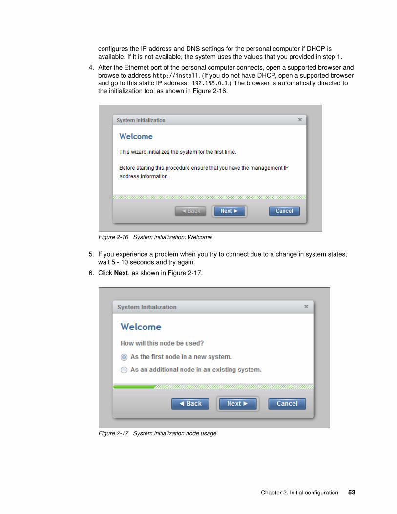
configures the IP address and DNS settings for the personal computer if DHCP is available. If it is not available, the system uses the values that you provided in step 1.
4. After the Ethernet port of the personal computer connects, open a supported browser and browse to address http://install. (If you do not have DHCP, open a supported browser and go to this static IP address: 192.168.0.1.) The browser is automatically directed to the initialization tool as shown in Figure 2-16.
Figure 2-16 System initialization: Welcome
5. If you experience a problem when you try to connect due to a change in system states, wait 5 - 10 seconds and try again.
6. Click Next, as shown in Figure 2-17.
Figure 2-17 System initialization node usage
Chapter 2. Initial configuration 53

7. Choose the first option to set up the node as a new system and click Next to continue to the window that is shown in Figure 2-18.
Figure 2-18 System initialization: Create a New System
8. Complete all of the fields with the networking details for managing the system and click Next. When the task completes, as shown in Figure 2-19, click Close.
Figure 2-19 System initialization: Cluster creation
54 Implementing the Lenovo Storage V3700 V2 and V5030 Systems

9. The system takes approximately 10 minutes to reboot and reconfigure the Web Server as shown in Figure 2-20. After this time, click Next to proceed to the final step.
Figure 2-20 System Initialization: Restarting Web Server
10.After you complete the initialization process, disconnect the cable between the personal computer and the technician port as instructed in Figure 2-21. Reestablish the connection to the customer network and click Next to be redirected to the management address that you provided to configure the system initially.
Figure 2-21 System initialization: Completion summary
Note: The Lenovo Storage V3700 V2, V3700 V2 XP, and V5030 GUI show the CLI as you go through the configuration steps.
Chapter 2. Initial configuration 55

2.10 Initial configuration
This section describes how to complete the initial configuration, including the following tasks:
� System components verification� Email event notifications� System name, date, and time settings� License functions� Initial storage configuration� Initial configuration summary
If you completed the initial setup, that wizard automatically redirects you to the Lenovo Storage V3700 V2, V3700 V2 XP, and V5030 GUI. Otherwise, complete the following steps to complete the initial configuration process:
1. Start the service configuration wizard by using a web browser on a workstation and point it to the system management IP address that was defined in Figure 2-18 on page 54. By clicking Accept, you certify that you agree to the terms and conditions, as shown in Figure 2-22
Figure 2-22 Setup wizard: License Agreement
56 Implementing the Lenovo Storage V3700 V2 and V5030 Systems

2. Enter a new secure password twice for the superuser user as shown in Figure 2-23 and click Log in.
Figure 2-23 Setup wizard: Password prompt
3. Verify the prerequisites in the Welcome window as shown in Figure 2-24 and click Next.
Figure 2-24 Setup wizard: Welcome
Chapter 2. Initial configuration 57

4. In the System Name window, enter the system name and click Apply and Next as shown in Figure 2-25.
Figure 2-25 Setup wizard: System Name
Note: Use the chsystem command to modify the attributes of the clustered system. This command can be used any time after a system is created.
58 Implementing the Lenovo Storage V3700 V2 and V5030 Systems

5. In the next window, the Lenovo Storage V3700 V2, V3700 V2 XP, and V5030 GUI provides help and guidance about additional licenses that are required for certain system functions. A license must be purchased for each enclosure that is attached to, or externally managed by, the Lenovo Storage V3700 V2, V3700 V2 XP, and V5030. For each of the functions, enter the number of enclosures as shown in Figure 2-26 and click Apply and Next.
Figure 2-26 Setup wizard: Licensed Functions
The following actions are required for each of the licensed functions:
– FlashCopy: Enter the number of enclosures that are licensed to use FlashCopy function.
– Remote copy: Enter the number of Remote Mirroring licenses. This license setting enables the use of Metro Mirror and Global Mirror functions. This value must be equal to the number of enclosures that are licensed for external virtualization, plus the number of attached internal enclosures.
– Easy Tier: Enter the number of enclosures that are licensed to use Easy Tier function.
– External Virtualization: Enter the number of external enclosures that you are virtualizing. An external virtualization license is required for each physical enclosure that is attached to your system.
– Real-time Compression (RtC): Enter the number of enclosures that are licensed to use RtC.
Chapter 2. Initial configuration 59

6. Two options are available for configuring the date and time. Select the required method and enter the date and time manually or specify a network address for a Network Time Protocol (NTP) server. After this selection, the Apply and Next option becomes active, as shown in Figure 2-27. Click Apply and Next.
Figure 2-27 Setup wizard: Date and Time
Encryption license: The encryption feature that is available on the Lenovo Storage V3700 V2 XP and Lenovo Storage V5030 systems use a special licensing system that differs from the licensing system for the other features. Encryption requires a license key that can be activated in step 7.
60 Implementing the Lenovo Storage V3700 V2 and V5030 Systems
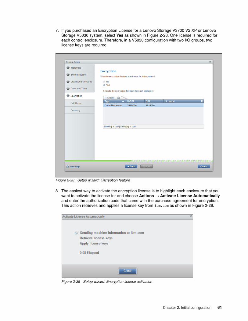
7. If you purchased an Encryption License for a Lenovo Storage V3700 V2 XP or Lenovo Storage V5030 system, select Yes as shown in Figure 2-28. One license is required for each control enclosure. Therefore, in a V5030 configuration with two I/O groups, two license keys are required.
Figure 2-28 Setup wizard: Encryption feature
8. The easiest way to activate the encryption license is to highlight each enclosure that you want to activate the license for and choose Actions → Activate License Automatically and enter the authorization code that came with the purchase agreement for encryption. This action retrieves and applies a license key from ibm.com as shown in Figure 2-29.
Figure 2-29 Setup wizard: Encryption license activation
Chapter 2. Initial configuration 61

9. If automatic activation cannot be performed, for example, if the Lenovo Storage V3700 V2, V3700 V2 XP, and V5030 systems are behind a firewall that prevents it from accessing the internet, choose Actions → Activate License Manually. Follow these steps:
a. Go to this website:
https://www.ibm.com/storage/dsfa
b. Select Storwize. Enter the machine type (6535 or 6536), serial number, and machine signature of the system. You can obtain this information by clicking Need Help.
c. Enter the authorization codes that were sent with your purchase agreement for the encryption function.
d. Copy or download the key and paste it into the management GUI to activate the license.
10.When all licenses are active, click Next to set up Call Home.
11.You can configure your system to send email reports to field support if an issue is detected that requires hardware replacement. This function is called Call Home. When this email is received, field support automatically opens a problem report and contacts you to verify whether replacements parts are required.
The Lenovo Storage V3700 V2, V3700 V2 XP, and V5030 can use Simple Network Management Protocol (SNMP) traps, syslog messages, and Call Home email to notify you and the Field Support Center when significant events are detected. Any combination of these notification methods can be used simultaneously.
To set up Call Home, you need the location details of the Lenovo Storage V3700 V2, V3700 V2 XP, and V5030, Storage Administrator details, and at least one valid SMTP server IP address. If you do not want to configure Call Home now, you can configure it later by using the GUI and clicking Settings → Notifications. For more information, see 2.10.3, “Configuring Call Home, email alert, and inventory” on page 75.
If your system is under warranty or you bought a hardware maintenance agreement, we advise you to configure Call Home to enable proactive support of the Lenovo Storage V3700 V2, V3700 V2 XP, and V5030.
Call Home: When Call Home is configured, the Lenovo Storage V3700 V2, V3700 V2 XP, and V5030 automatically create a Support Contact with one of the following email addresses, depending on the country or region of installation:
� US, Canada, Latin America, and Caribbean Islands: [email protected]� All other countries or regions: [email protected]
62 Implementing the Lenovo Storage V3700 V2 and V5030 Systems

12.Enter the system location information. These details appear on the Call Home data to enable field Support to correctly identify where the Lenovo Storage V3700 V2, V3700 V2 XP, and V5030 arelocated, as shown in Figure 2-30.
Figure 2-30 Setup wizard: System Location
Important: Unless the Lenovo Storage V3700 V2, V3700 V2 XP, and V5030 are in the US, you must enter XX in the state or province field. Follow the help for the correct entries for locations inside the US.
Chapter 2. Initial configuration 63

13.In the next window, you must enter the contact details of the main storage administrator, as shown in Figure 2-31. You can choose to enter the details for a 24-hour operations desk. These details also are sent with any Call Home. Field Support uses this information to contact the correct people quickly if an issue occurs.
Figure 2-31 Setup wizard: Contact details
14.Click Apply and Next.
64 Implementing the Lenovo Storage V3700 V2 and V5030 Systems

15.The next window is for email server details. To enter more than one email server, click the plus sign (+) icon, as shown in Figure 2-32. Then, click Apply and Next to commit.
Figure 2-32 Initial setup: Email server details
Chapter 2. Initial configuration 65

16.The Summary window for the contact details, system location, email server, Call Home, and email notification options is shown in Figure 2-33. After you click Finish, the web browser is redirected to the management GUI.
Figure 2-33 Initial setup: Summary
66 Implementing the Lenovo Storage V3700 V2 and V5030 Systems

2.10.1 Configuring storage
The first time that you log in to the management GUI after you complete the initial setup, you are prompted to create storage pools as shown in Figure 2-34. You must create the storage pools before you create the volumes.
Figure 2-34 Suggested task: Create Pools
Click Create Pools to create the first storage pool. Enter a name for the pool and click Create. After you create the first pool, you are prompted to create arrays as shown in Figure 2-35.
Figure 2-35 Suggested task: Create Arrays
Before the internal drives in the Lenovo Storage V3700 V2, V3700 V2 XP, and V5030 can be used, they must first be managed by one or more RAID arrays to provide redundancy if a disk failure occurs. For more information about configuring pools and arrays, see Chapter 7, “Storage pools” on page 253.
Chapter 2. Initial configuration 67

2.10.2 Adding enclosures after the initial configuration
When the initial installation of the Lenovo Storage V3700 V2, V3700 V2 XP, and V5030 are complete, all expansion enclosures and control enclosures that were purchased at that time must be installed as part of the initial configuration. This process enables the system to make the best use of the enclosures and drives that are available.
Adding a control enclosureIf you are expanding the Lenovo Storage V3700 V2, V3700 V2 XP, and V5030 after the initial installation by adding a second I/O group (a second control enclosure), you must install it in the rack and connect it to the SAN. Ensure that you rezone your Fibre Channel switches so that the new control enclosure and the existing control enclosure are connected. For more information about zoning the node canisters, see 2.2, “SAN configuration planning” on page 38.
After the hardware is installed, cabled, zoned, and powered on, a second control enclosure is visible from the Lenovo Storage V3700 V2, V3700 V2 XP, and V5030 GUI, as shown in Figure 2-36.
Figure 2-36 Second control enclosure
68 Implementing the Lenovo Storage V3700 V2 and V5030 Systems

Complete the following steps to use the management GUI to configure the new enclosure:
1. In the main window, click Actions in the upper-left corner and select Add Enclosures. Alternatively, you can click the available control enclosure as shown in Figure 2-37.
Figure 2-37 Option to add a control enclosure
Chapter 2. Initial configuration 69

2. If the control enclosure is configured correctly, the new control enclosure is identified in the next window, as shown in Figure 2-38.
Figure 2-38 New control enclosure identification
3. Select the control enclosure and click Actions → Identify to turn on the identify LEDs of the new enclosure, if required. Otherwise, click Next.
70 Implementing the Lenovo Storage V3700 V2 and V5030 Systems

4. The new control enclosure is added to the system as shown in Figure 2-39. Click Finish to complete the operation.
Figure 2-39 Added enclosure summary
5. When the new enclosure is added, the storage that is provided by the internal drives is available to use as shown in Figure 2-40.
Figure 2-40 Adding storage completed
Chapter 2. Initial configuration 71

6. After the wizard completes the addition of the new control enclosure, the Lenovo Storage V3700 V2, V3700 V2 XP, and V5030 show the management GUI that contains two I/O groups, as shown in Figure 2-41.
Figure 2-41 Lenovo Storage V3700 V2, V3700 V2 XP, and V5030 GUI with two I/O groups
Adding an expansion enclosureComplete the following steps to add an expansion controller:
1. To add an expansion enclosure, change to the Monitoring tab and select System. If no new hardware is shown, check your cabling to ensure that the new expansion enclosure is connected correctly and refresh the window.
In the main window, click Actions in the upper-left corner and select Add Enclosures. Alternatively, you can click the available expansion enclosure as shown in Figure 2-42.
Figure 2-42 Adding an expansion enclosure
72 Implementing the Lenovo Storage V3700 V2 and V5030 Systems

2. If the enclosure is cabled correctly, the wizard identifies the candidate expansion enclosure. Select the expansion enclosure and click Next, as shown in Figure 2-43.
Figure 2-43 Expansion enclosure cable check
3. Select the expansion enclosure and click Actions → Identify to turn on the identify LEDs of the new enclosure, if required. Otherwise, click Next.
Chapter 2. Initial configuration 73

4. The new expansion enclosure is added to the system as shown in Figure 2-44. Click Finish to complete the operation.
Figure 2-44 Added enclosure summary
5. After the expansion enclosure is added, the Lenovo Storage V3700 V2, V3700 V2 XP, and V5030 show the management GUI that contains two enclosures, as shown in Figure 2-45.
Figure 2-45 Lenovo Storage V3700 V2, V3700 V2 XP, and V5030 GUI with two enclosures in a single I/O group
74 Implementing the Lenovo Storage V3700 V2 and V5030 Systems

2.10.3 Configuring Call Home, email alert, and inventory
If your system is under warranty or you bought a hardware maintenance agreement, we advise you to configure your system to send email reports to field support. If an issue occurs that requires hardware investigation, the Lenovo Storage V3700 V2, V3700 V2 XP, and V5030 send an email to the support teams at Lenovo, creates a problem record, and alerts the support teams about the issue. A Lenovo Support representative contacts you proactively to investigate the issue. This feature is known as Call Home. It is typically configured during the initial configuration of the system.
To configure Call Home and email alert event notification in the Lenovo Storage V3700 V2, V3700 V2 XP, and V5030 after the initial configuration, complete the following steps:
1. Click Settings → Notifications, as shown in Figure 2-46.
Figure 2-46 Enabling Call Home
Chapter 2. Initial configuration 75

2. If email notification is disabled on your system, as shown in Figure 2-47, you can enable it by clicking Enable Notifications.
Figure 2-47 Enabling email notifications
If the email and Call Home notifications were never configured in the Lenovo Storage V3700 V2, V3700 V2 XP, and V5030, a window opens and the wizard guides you to the steps that are described in 2.10, “Initial configuration” on page 56.
3. Click Notifications → Email as shown in Figure 2-48.
Figure 2-48 Selecting event notifications
76 Implementing the Lenovo Storage V3700 V2 and V5030 Systems

The fields to configure Call Home are shown. You must enter accurate and complete information about both your company and the contact. The email contact is the person who is contacted by the Lenovo Support Center about any issues and for more information. You can enter a network operations center email address in this field for 24x7 coverage. Enter the IP address and the server port for one or more of the email servers that send an email to field support.
If you want email alerts to be sent to recipients in addition to the field support, add their addresses in the Email Notifications section. Click the plus sign (+) to add more recipients and select one or more event types for each user, as shown in Figure 2-49.
Figure 2-49 Setting up Call Home
4. Click Save to save the changes.
2.10.4 Service Assistant Tool
The Lenovo Storage V3700 V2, V3700 V2 XP, and 5030, as a single I/O group, are configured initially with three IP addresses, one service IP address for each node canister, and a management IP address, which is set when the cluster is started.
The management IP and service IP addresses can be changed within the GUI as shown in Chapter 3, “Graphical user interface overview” on page 81.
Chapter 2. Initial configuration 77

Service Assistant (SA) Tool is a web-based GUI that is used to service individual node canisters, primarily when a node has a fault and it is in a service state. A node cannot be active as part of a clustered system while the node is in a service state. The SA Tool is available even when the management GUI is not accessible. The following information and tasks are included:
� Status information about the connections and the node canister
� Basic configuration information, such as configuring IP addresses
� Service tasks, such as restarting the Common Information Model object manager (CIMOM) and updating the worldwide node name (WWNN)
� Details about node error codes and hints about how to fix the node error
The Service Assistance GUI is available by using a service assistant IP address on each node. The SA GUI is accessed through the cluster IP addresses by appending service to the cluster management URL. If the system is down, the only other method of communicating with the node canisters is through the SA IP address directly. Each node can have a single SA IP address on Ethernet port 1. We advise that these IP addresses are configured on all of the Lenovo Storage V3700 V2, V3700 V2 XP, and V5030 node canisters.
The default IP address of canister 1 is 192.168.70.121 with a subnet mask of 255.255.255.0.
The default IP address of canister 2 is 192.168.70.122 with a subnet mask of 255.255.255.0.
To open the SA GUI, enter one of the following URLs into any web browser:
� http(s)://cluster IP address of your cluster/service � http(s)://service IP address of a node/service
The following examples open the SA GUI:
� Management address: http://1.2.3.4/service � SA access address: http://1.2.3.5/service
Important: Service Assistant Tool can be accessed by using the superuser account only. You must access Service Assistant Tool under the direction of Lenovo Support only.
78 Implementing the Lenovo Storage V3700 V2 and V5030 Systems

When you access SA by using the <cluster address>/service, the configuration node canister SA GUI login window opens, as shown in Figure 2-50.
Figure 2-50 Service Assistant Tool login
The SA interface can view status and run service actions on other nodes and the node where the user is connected.
Chapter 2. Initial configuration 79

After you are logged in, you see the Service Assistant Tool Home window, as shown in Figure 2-51.
Figure 2-51 Service Assistant Tool Home window
The current canister node is displayed in the upper-left corner of the GUI. As shown in Figure 2-51, the current canister node is node 1. To change the canister, select the relevant node in the Change Node section of the window. You see that the details in the upper-left corner change to reflect the new canister.
The SA GUI provides access to service procedures and shows the status of the node canisters. We advise that you perform these procedures only if you are directed to use them by IBM Support.
For more information about how to use the SA Tool, see this website:
https://ibm.biz/BdrDiW
80 Implementing the Lenovo Storage V3700 V2 and V5030 Systems

Chapter 3. Graphical user interface overview
This chapter provides an overview of the graphical user interface (GUI) of IBM Spectrum Virtualize on the Lenovo Storage V3700 V2, V3700 V2 XP, and V5030 and shows you how to use the navigation tools.
This chapter includes the following topics:
� 3.1, “Overview of IBM Spectrum Virtualize management software” on page 82� 3.2, “Overview pane” on page 91� 3.3, “Monitoring menu” on page 91� 3.4, “Pools menu” on page 98� 3.5, “Volumes menu” on page 108� 3.6, “Hosts menu” on page 113� 3.7, “Copy services” on page 117� 3.8, “Access menu” on page 124� 3.9, “Settings menu” on page 128
3
© Copyright Lenovo 2018. All rights reserved. 81
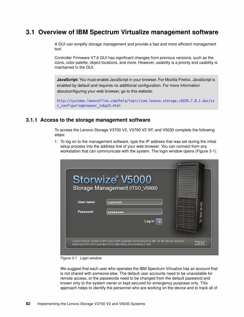
3.1 Overview of IBM Spectrum Virtualize management software
A GUI can simplify storage management and provide a fast and more efficient management tool.
Controller Firmware V7.6 GUI has significant changes from previous versions, such as the icons, color palette, object locations, and more. However, usability is a priority and usability is maintained in the GUI.
3.1.1 Access to the storage management software
To access the Lenovo Storage V3700 V2, V3700 V2 XP, and V5030 complete the following steps:
1. To log on to the management software, type the IP address that was set during the initial setup process into the address line of your web browser. You can connect from any workstation that can communicate with the system. The login window opens (Figure 3-1).
Figure 3-1 Login window
We suggest that each user who operates the IBM Spectrum Virtualize has an account that is not shared with someone else. The default user accounts need to be unavailable for remote access, or the passwords need to be changed from the default password and known only to the system owner or kept secured for emergency purposes only. This approach helps to identify the personnel who are working on the device and to track all of
JavaScript: You must enable JavaScript in your browser. For Mozilla Firefox, JavaScript is
enabled by default and requires no additional configuration. For more information
aboutconfiguring your web browser, go to this website:
http://systemx.lenovofiles.com/help/topic/com.lenovo.storage.v5030.7.8.1.doc/svc_configuringbrowser_1obg15.html
82 Implementing the Lenovo Storage V3700 V2 and V5030 Systems

the important changes in the systems. The Superuser account must be used for initial configuration only.
2. After a successful login, the IBM Spectrum Virtualize System pane displays the controller and an empty box graphic, as shown in Figure 3-2. An enclosure is added to this box, as shown in the next few steps.
Figure 3-2 A first view
3. To add an enclosure, click the empty box graphic and select the hardware that you want to add (Figure 3-3).
Figure 3-3 Adding an enclosure
Chapter 3. Graphical user interface overview 83

4. The next window shows information about the hardware that was added and licensing information, as shown in Figure 3-4.
Figure 3-4 Summary and finish after you add hardware
Figure 3-5 shows a message that the addition of the storage enclosure is complete.
Figure 3-5 Storage enclosure addition completed
The System pane is an important user interface. Throughout this chapter, we refer to it as the System pane. In the remaining chapters, we do not explain how to access it each time.
84 Implementing the Lenovo Storage V3700 V2 and V5030 Systems

3.1.2 System pane layout
The System pane has four main sections for navigating through the management tool:
� Top
The top menu shows the navigation path so that the user knows the exact path.
The Actions option can be used at any time to add more enclosures, modify existing hardware, or rename the system.
The top menu also has a system overview so that you can see global system topology.
� Left
The system menu (or set of function icons) is the main object that the users access. By using the system menu, the user can change or view any setting or parameter in the system.
� Center
Within the system view object, users can view or change parameters that mainly relate to the hardware of global system settings.
� Bottom
The informational pane consists of running tasks, capacity information, basic performance indicator (new since version 7.5), system health status, and status alerts.
Figure 3-5 shows these four main areas.
Figure 3-6 Main areas
Chapter 3. Graphical user interface overview 85

The main areas are described:
� The left side of the window shows seven function icons. We refer to them collectively as a dynamic menu. The dynamic menu includes these function icons:
– Monitoring menu– Pools menu– Volumes menu– Hosts menu– Copy Services menu– Access menu– Settings menu
� The middle of the window shows a component model of the existing configuration. Hovering the mouse cursor over each component and its part highlights that part and provides a pop-up menu with a description that identifies important parameters and functions of this element. To see the rear of the component, you can dynamically rotate them as in a typical 360° view. Right-clicking a component or its part opens its menu with actions, which are normally available from the dynamic menu on the left.
� The bottom of the window shows five status indicators. Clicking any of them provides more detailed information about the existing configuration of the IBM Spectrum Virtualize solution. Click any of these function icons to expand them and minimize them as required, or to switch between different types of information, for example, virtual or allocated storage. In an error or warning, those indicators are extended by the status alerts icon in the lower-right corner (Figure 3-6 on page 85).
3.1.3 Navigation
Navigating in the management tool is simple. You can hover the cursor over one of the seven function icons to emphasize that icon and display a menu of options. You can move the cursor to an option and click it. Figure 3-7 shows how to access, for example, the Pools option.
Figure 3-7 Navigate by using the menu options
86 Implementing the Lenovo Storage V3700 V2 and V5030 Systems

3.1.4 Multiple selection
With the improved management tool, you can select multiple items by using the Shift and Ctrl keys. To select multiple items in a display, click the first item, press and hold the Shift key, and click the last item that you require in the list. All rows between those two items are selected and highlighted in light blue (Figure 3-8).
Figure 3-8 Multiple selections by using the Shift key
Similarly, if you want to select multiple items that are not in sequential order, click the first item, press and hold the Ctrl key, and click the other items that you need (Figure 3-9).
Figure 3-9 Multiple selections by using the Ctrl key
Chapter 3. Graphical user interface overview 87
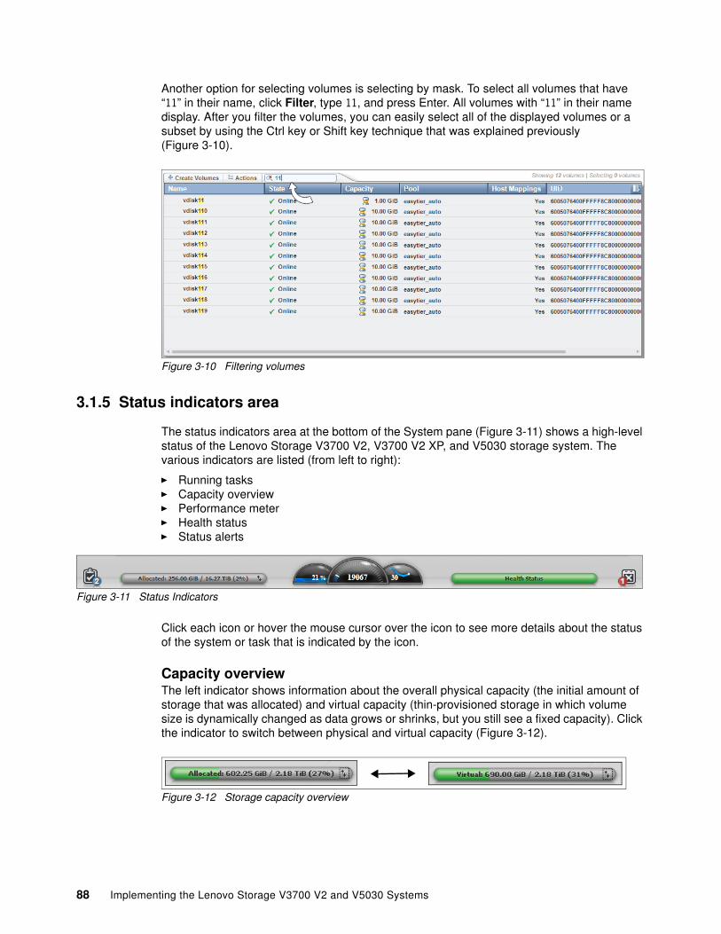
Another option for selecting volumes is selecting by mask. To select all volumes that have “11” in their name, click Filter, type 11, and press Enter. All volumes with “11” in their name display. After you filter the volumes, you can easily select all of the displayed volumes or a subset by using the Ctrl key or Shift key technique that was explained previously (Figure 3-10).
Figure 3-10 Filtering volumes
3.1.5 Status indicators area
The status indicators area at the bottom of the System pane (Figure 3-11) shows a high-level status of the Lenovo Storage V3700 V2, V3700 V2 XP, and V5030 storage system. The various indicators are listed (from left to right):
� Running tasks� Capacity overview� Performance meter� Health status� Status alerts
Figure 3-11 Status Indicators
Click each icon or hover the mouse cursor over the icon to see more details about the status of the system or task that is indicated by the icon.
Capacity overviewThe left indicator shows information about the overall physical capacity (the initial amount of storage that was allocated) and virtual capacity (thin-provisioned storage in which volume size is dynamically changed as data grows or shrinks, but you still see a fixed capacity). Click the indicator to switch between physical and virtual capacity (Figure 3-12).
Figure 3-12 Storage capacity overview
88 Implementing the Lenovo Storage V3700 V2 and V5030 Systems

Running tasksThe Running Tasks indicator on the left provides information about jobs that were initiated by the user or system and that typically run for a longer period, such as array initialization, synchronization, or rebuild. Hover the mouse cursor over the memorandum book icon on the indicator to open the Running Tasks status, which lists all running tasks (Figure 3-13).
Figure 3-13 Running tasks status
Health statusThe right Health status indicator warns administrators about critical errors or alerts that need greater attention. In a critical alert, the green color of the indicator becomes red. You can then click the X icon (Figure 3-14) to open the menu to see the status alerts. If the status is healthy (green, not red), no menu is available. A yellow color indicates a warning only.
Figure 3-14 Health status of the system
Important: Since version 7.4, the capacity units use the binary prefixes that are defined by the International Electrotechnical Commission (IEC), representing a multiplication by 1024 with symbols GiB (gibibyte), TiB (tebibyte), and PiB (pebibyte).
Chapter 3. Graphical user interface overview 89

Status alertsThe indicator for Status Alerts is at the lower-right corner. It displays only if an important error or warning exists that was not acknowledged or fixed in the event log. Hover the mouse cursor over the icon to see the list of important system messages (Figure 3-15). After all alerts are cleared from the system, the Status Alerts icon is no longer displayed.
Figure 3-15 Lenovo Storage V3700 V2, V3700 V2 XP, and V5030 status alerts
HelpAnother useful interface feature is integrated help. You can access help for certain fields and objects by hovering the mouse cursor over the question mark (?) icon next to the field or object (Figure 3-16). Panel-specific help is available by clicking Need Help or by using the Help link in the upper-right corner of the GUI.
Figure 3-16 Access to panel-specific help
90 Implementing the Lenovo Storage V3700 V2 and V5030 Systems

3.2 Overview pane
The welcome pane of the GUI changed from the well-known former Overview pane to the new System pane, as shown in Figure 3-17. Clicking Overview in the upper-right corner of the System pane opens a modified Overview pane with similar functionality as in previous versions of the software.
Figure 3-17 Opening the Overview pane
See 3.1.2, “System pane layout” on page 85 to understand the structure of the pane and how to navigate to various system components and manage them more efficient and quickly.
3.3 Monitoring menu
Hover the cursor over the Monitoring function icon to open the Monitoring menu (Figure 3-18 on page 92). The Monitoring menu offers the following navigation directions:
System Opens the general overview of your Lenovo Storage V3700 V2, V3700 V2 XP, and V5030 systems, including the depiction of all devices in a rack and the storage capacity. See 3.3.1, “System overview” on page 92.
Events Tracks all informational, warning, and error messages that occurred in the system. You can apply various filters to sort them according to your needs or export them to an external comma-separated values (CSV) file. See 3.3.3, “Events” on page 97.
Performance Reports the general system statistics about processor (CPU) use, host and internal interfaces, volumes, and managed disks (MDisk). You can switch between megabytes per second (MBps) or input/output operations per second (IOPS). See 3.3.4, “Performance” on page 97.
Chapter 3. Graphical user interface overview 91

In V7.4 and later, the option that was known as System Details is integrated into the device overview on the general System pane, which is available after login or when you click System from the Monitoring menu. The details are shown in 3.3.2, “System details” on page 95.
Figure 3-18 Accessing the Monitoring menu
In the following sections, we describe each option on the Monitoring menu.
3.3.1 System overview
The System option on the Monitoring menu provides a general overview about your for Lenovo Storage V3700 V2, V3700 V2 XP, and V5030 systems, including the depiction of all devices in a rack and the allocated or physical storage capacity. When thin-provisioned or compressed volumes are enabled, the virtual capacity is also shown by hovering your mouse over the capacity indicator. See Figure 3-19 for details.
Figure 3-19 System overview that shows capacity
92 Implementing the Lenovo Storage V3700 V2 and V5030 Systems
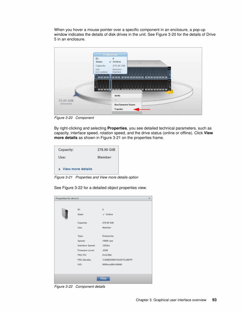
When you hover a mouse pointer over a specific component in an enclosure, a pop-up window indicates the details of disk drives in the unit. See Figure 3-20 for the details of Drive 5 in an enclosure.
Figure 3-20 Component
By right-clicking and selecting Properties, you see detailed technical parameters, such as capacity, interface speed, rotation speed, and the drive status (online or offline). Click View more details as shown in Figure 3-21 on the properties frame.
Figure 3-21 Properties and View more details option
See Figure 3-22 for a detailed object properties view.
Figure 3-22 Component details
Chapter 3. Graphical user interface overview 93

In an environment with multiple Lenovo Storage V3700 V2, V3700 V2 XP, and V5030 systems, you can easily navigate the onsite personnel or technician to the correct device by enabling the identification LED on the front pane. First, right-click the enclosure that you want to identify. Then, click Identify in the pop-up window that is shown in Figure 3-23 and wait for the confirmation from the technician that the device in the data center was identified correctly.
After the confirmation, click Turn LED Off (Figure 3-23).
Figure 3-23 Using the identification LED
Alternatively, you can use the IBM Spectrum Virtualize command-line interface (CLI) to obtain the same results. Type the following sequence of commands:
� svctask chenclosure -identify yes 1 (or just chenclosure -identify yes 1)� svctask chenclosure -identify no 1 (or just chenclosure -identify no 1)
You can use the same CLI to obtain results for a specific controller or drive.
Each system that is shown in the dynamic system view in the middle of a System pane can be rotated by 180° to see its rear side. Click the rotation arrow in the lower-right corner of the device, as illustrated in Figure 3-24.
Figure 3-24 Rotating the enclosure
94 Implementing the Lenovo Storage V3700 V2 and V5030 Systems

3.3.2 System details
The System Details option was removed from the Monitoring menu. However, its modified information is still available directly from the System pane. The Properties option provides the extended level of parameters and technical details that relate to the system, including the integration of each element with an overall system configuration. Right-click the enclosure that you want and navigate to the Properties option to obtain the detailed information (Figure 3-25).
Figure 3-25 System details
The output is shown in Figure 3-26. By using this menu, you can also power off the machine (without the option for remote start), remove the node or enclosure from the system, or list all volumes that are associated with the system (Show Dependent Volumes).
Figure 3-26 Enclosure technical details under the Properties option
Chapter 3. Graphical user interface overview 95
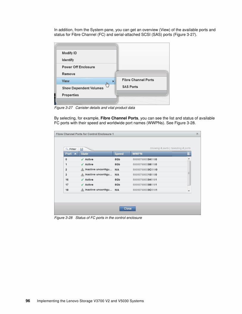
In addition, from the System pane, you can get an overview (View) of the available ports and status for Fibre Channel (FC) and serial-attached SCSI (SAS) ports (Figure 3-27).
Figure 3-27 Canister details and vital product data
By selecting, for example, Fibre Channel Ports, you can see the list and status of available FC ports with their speed and worldwide port names (WWPNs). See Figure 3-28.
Figure 3-28 Status of FC ports in the control enclosure
96 Implementing the Lenovo Storage V3700 V2 and V5030 Systems

3.3.3 Events
The Events option, which is selected from the Monitoring menu (Figure 3-18 on page 92), tracks all informational, warning, and error messages that occur in the system. You can apply various filters to sort them or export them to an external CSV file. A CSV file can be created from the information that is included in the Events list. Figure 3-29 shows the display after you click Events from the Monitoring menu.
Figure 3-29 Events log
The procedures for how to work with the events log and how to run various fix procedures by using the Events option are described in Chapter 12, “RAS, monitoring, and troubleshooting” on page 575.
3.3.4 Performance
The Performance pane reports the general system statistics that relate to processor (CPU) use, host and internal interfaces, volumes, and MDisks. You can switch between MBps or IOPS, or even navigate to the statistics at the node level. The Performance pane might be useful when you compare the performance of each node in the system if problems exist after a node failover occurs. See Figure 3-30.
Figure 3-30 Performance statistics of the Lenovo Storage V3700 V2, V3700 V2 XP, and V5030 system
Chapter 3. Graphical user interface overview 97

The performance statistics in the GUI show, by default, the last 5 minutes of data. To see the details of each sample, click the graph and select the time stamp, as shown in Figure 3-31.
Figure 3-31 Sample details
The previous charts represent 5 minutes of the data stream.
3.4 Pools menu
A pool or storage pool is a collection of MDisks that jointly contain all of the data for a specified set of volumes. All MDisks in a pool are split into extents of the same size. Volumes are created from the extents that are available in the pool. You can add MDisks to a storage pool at any time, either to increase the number of extents that are available for new volume copies or to expand existing volume copies.
Hover the cursor over the Pools function icon to display the Pools menu options (Figure 3-32).
Figure 3-32 Navigate to the Pools menu
The Pools menu includes the following options:
Pools Shows a list of pools that are already available within the system. It provides an option to create or modify pools and child pools, adding additional storage.
Volumes by Pool Applies the high-level filter, listing all defined volumes per pool. It also provides a capacity overview, which is valid for a specific, selected
98 Implementing the Lenovo Storage V3700 V2 and V5030 Systems

pool only. This view is excellent when you plan a migration of a volume to another pool so that you have a common overview of all pools and their associated volumes. Unused volumes are not listed.
Internal Storage Provides an overview of all disk drives that are installed in the Lenovo Storage V3700 V2, V3700 V2 XP, and V5030 system, including its enclosures. You can filter based on disk type and capacity and also see unused volumes that are not assigned to any pool.
External Storage Shows all pools and their volumes that are created from the systems that connect to the Lenovo Storage V3700 V2, V3700 V2 XP, and V5030 externally and that are integrated in the system repository. It does not show any internal pools or volumes. This type of storage is also called external virtualization.
MDisks by Pools Provides the list of all managed disks (MDisks) that are either internally or externally connected and associated with one of the defined pools. It also lists all unassigned MDisks separately.
System Migration Offers the migration wizard to import data from image-mode MDisks to a specific pool. It is useful when you migrate data nondisruptively to the hosts from old external storage to the Lenovo Storage V3700 V2, V3700 V2 XP, and V5030.
Chapter 3. Graphical user interface overview 99

3.4.1 Pools
If you plan to add storage to an existing pool, use the main Pools view. Right-click an existing pool (or create a pool in advance and add the storage) and select Add Storage as shown in Figure 3-33.
Figure 3-33 Add Storage option
In the next window, you can either select Internal or Internal custom. See Figure 3-34.
Figure 3-34 Internal storage selection
100 Implementing the Lenovo Storage V3700 V2 and V5030 Systems

Figure 3-35 shows the window if you select Internal. Choose the default (Quick) settings to create a new MDisk for the pool.
Figure 3-35 Internal storage selection
Chapter 3. Graphical user interface overview 101

Figure 3-36 shows you the window if you selected the Internal Custom storage panel.
Figure 3-36 Internal Custom storage selection
You can choose from the available drive classes (depending on the installed drives) and RAID sets.
3.4.2 Child pools
Before V7.4, the disk space of a storage pool was provided from MDisks so the capacity of a storage pool depended on the MDisks’ capacity. Creating or splitting a storage pool is impossible. A user cannot create a storage pool and specify the capacity that they want. A child pool is a new logical object that is created from a physical storage pool. A child pool provides most of the functions that pools offer (for example, volume creation), but the user can specify the capacity of the child pool at creation.
A child pool is an object that is similar to a storage pool, and a child pool can be used interchangeably with a storage pool. A child pool supports volume copy and migration. However, limitations and restrictions exist for child pools:
� The maximum capacity cannot exceed the parent pool’s size.� The capacity can be allocated at creation (thick) or flexible (thin).� You must always specify the parent storage pool. The child pool does not own any
MDisks.� Child pools can also be created by using the GUI.� The maximum number of child pools in one parent pool is 127.� You are restricted to migrating image-mode volumes to a child pool.� Volume extents cannot be migrated out of the child pool.
102 Implementing the Lenovo Storage V3700 V2 and V5030 Systems

� You cannot shrink capacity smaller than the real capacity.
You can view the list of child pools from the Pools menu option by clicking the plus sign (+) of a parent pool, as shown in Figure 3-37.
Figure 3-37 Working with child pools
3.4.3 Volumes by pool
The Volumes by Pool menu option lists all defined volumes, which are sorted by their pool assignment (Figure 3-38). Unassigned volumes are not visible in this window. By using this window, you can, for example, create volumes, map or unmap volumes to and from hosts, migrate volumes to another pool, and rename, shrink, or expand volumes.
In addition, you can choose a different icon (Figure 3-38) that represents this pool.
Figure 3-38 Volume by Pool option and changing the icon
Chapter 3. Graphical user interface overview 103

Also, you can rename the pool (Figure 3-39).
Figure 3-39 Volume by pool and renaming the pool
When the pools are defined and the volumes are assigned, the pool shows one of the following operational states:
Online The storage pool is online and available. All of the MDisks in the storage pool are available.
Degraded path One or more nodes in the clustered system cannot access all of the MDisks in the pool. A degraded path state is most likely the result of the incorrect configuration of either the storage system or the FC fabric. However, hardware failures in the storage system, FC fabric, or node can also be a contributing factor to this state.
Degraded ports One or more 1220 errors were logged against the MDisks in the storage pool. The 1220 error indicates that the remote FC port was excluded from the MDisk. This error might cause reduced performance on the storage system and usually indicates a hardware problem with the storage system.
To fix this problem, you must resolve any hardware problems on the storage system and fix the 1220 errors in the event log. To resolve these errors in the log, select Troubleshooting → Recommended Actions in the management GUI.
This action displays a list of unfixed errors that are in the event log. For these unfixed errors, select the error name to begin a guided maintenance procedure to resolve the errors. Errors are listed in descending order with the highest priority error listed first. Resolve the highest priority errors first.
Offline The storage pool is offline and unavailable. No nodes in the system can access the MDisks. The most likely cause is that one or more MDisks are offline or excluded.
Important: In this view, volumes from child pools are shown the same way as volumes from standard pools. The relationships between the child and parent pools are not visible.
104 Implementing the Lenovo Storage V3700 V2 and V5030 Systems

3.4.4 Internal storage
Click the Internal Storage option in the Pools menu to open a window similar to Figure 3-40. From this window, you can allocate Redundant Array of Independent Disks (RAID) arrays of internal disk drives into storage pools. This window also offers the option to display internal drives, based on their capacity and speed.
Figure 3-40 Internal storage window
Click Actions in the table header, or right-click a specific drive to take the drive offline, show its properties, or mark the drive as Unused, Candidate, or Spare.
3.4.5 External storage
Clicking the External Storage option opens the window as shown in Figure 3-41. It provides the list of all externally connected (storage area network (SAN)-attached) disk systems to the Lenovo Storage V3700 V2, V3700 V2 XP, and V5030.
When the new external storage system is zoned correctly to the Lenovo Storage V3700 V2, V3700 V2 XP, and V5030, run the Discover storage procedure either from the Actions menu in the table header or by right-clicking any of the existing MDisks in the list (Figure 3-41).
Figure 3-41 Detecting external storage systems
Chapter 3. Graphical user interface overview 105

A new storage controller (external storage system) is listed automatically when the SAN zoning is configured, but typically without detected disk drives (Figure 3-42).
Figure 3-42 Automatically detected new external storage system
By right-clicking a newly detected storage system, you can rename the controller’s default name, in our case, the IBM System Storage FlashSystem 840, to reflect the real type of the storage device. We suggest that you use a simple naming convention, which in our case is FlashSystem 840 (Figure 3-43).
Figure 3-43 Renaming the detected system
After the new external storage system is named correctly, detect all disks that are configured on that external storage, in our case, System Storage FlashSystem 840. You can also discover storage from the CLI by using the svctask detectmdisk command or detectmdisk. Figure 3-44 shows details about detected managed disks.
Figure 3-44 Newly discovered managed disks
106 Implementing the Lenovo Storage V3700 V2 and V5030 Systems

All newly discovered disks are always interpreted in an unmanaged mode. You must assign them to the specific pool to be able to operate them.
3.4.6 MDisks by pools
This option on the Pools menu provides the list of all managed disks and arrays of disks, either internally or externally connected, and associated with one of the defined pools. It also lists all unassigned MDisks separately. An example of the pane is shown in Figure 3-45.
Figure 3-45 List of managed disks that are sorted within pools
All disks that are not yet assigned to any pool are listed in the Unassigned MDisks section. This section is always at the top of the list, even if you sort the list by pool name (clicking the Name header of the table). Right-click a specific disk to open a window where you can assign selected unmanaged disks to the pool.
From the same pane, you can define a new storage pool by clicking Create Pool in the upper-left corner of the table (highlighted in Figure 3-45). The wizard window opens and you need to specify pool parameters, such as Pool Name, Extent Size, and Warning Threshold. You can directly select Unmanaged MDisks that you want to include in the pool, or skip this task and add MDisks later.
3.4.7 System migration
Migrating data from older storage systems to the Lenovo Storage V3700 V2, V3700 V2 XP, and V5030 storage systems enable applications to benefit from the new features, such as IBM Easy Tier, Space Efficient volumes, an intuitive management GUI, and advanced storage replication functions that better support applications.
Important: The MDisks are not physical disk drives, but storage arrays that are configured on external systems.
If you add a managed disk that contains existing data to a managed disk group, you lose the data that it contains. The image mode is the only mode that preserves its data.
Note: All sort functions in the header of the table apply to MDisks within pools. You cannot sort volumes based on specific criteria across all pools.
Chapter 3. Graphical user interface overview 107

To migrate existing data, use the IBM Spectrum Virtualize storage migration wizard to guide you through the procedure. This wizard is available by selecting Pools → System Migration as shown in Figure 3-46.
The migration of external volumes to the Lenovo Storage V3700 V2, V3700 V2 XP, and V5030 system is one of the key benefits and features of external storage virtualization that are provided by this product. Therefore, we dedicate a whole chapter to this topic. See Chapter 6, “Storage migration” on page 221 for detailed steps of the migration process.
Figure 3-46 System migration
At any time, you can pause the running migration processes or create a new one. No license for External Virtualization is required to migrate from old storage to your new Lenovo Storage V3700 V2, V3700 V2 XP, and V5030.
3.5 Volumes menu
A volume is a logical disk that the system presents to the attached host. Application servers access volumes, not MDisks or drives. Volumes have additional characteristics. They can be automatically expanded, mirrored, or pre-allocated. Volumes can also be generic, thin-provisioned, or compressed.
108 Implementing the Lenovo Storage V3700 V2 and V5030 Systems

The following list provides a description of the volume characteristics and differences:
Generic A generic (fully allocated) volume is the traditional data store method when any host input/output (I/O) is destaged to the drives. Even zeros are destaged. All of the zeros that exist are written.
Thin-provisioned When you create a volume, you can designate it as thin-provisioned. A thin-provisioned volume has a virtual capacity and a real capacity. Virtual capacity is the volume storage capacity that is available to a host. Real capacity is the storage capacity that is allocated to a volume copy from a storage pool.
In a fully allocated volume, the virtual capacity and real capacity are the same. In a thin-provisioned volume, the virtual capacity can be much larger than the real capacity.
Compressed This volume is a special type of volume where data is compressed and thin-provisioned at the same time. Any compressed volume is a thin-provisioned volume by default, and no option is available to change this characteristic. Data within the compressed volume is compressed as it is written to disk. This design saves additional space on the storage drive so that you can store more data within the same storage system.
To keep a volume accessible even when an MDisk on which it depends is unavailable, a mirrored copy can be added to a selected volume. Any volume (generic, thin-provisioned, or compressed) can be mirrored with a mirror from any type, even the same one. Therefore, a volume can be either thin-provisioned with compressed copy or compressed with compressed copy. Each volume can have a maximum of two copies.
Each volume copy is created from a set of extents in a storage pool. By using volume mirroring, a volume can have two physical copies. Each volume copy can belong to a different storage pool, and each copy has the same virtual capacity as the volume. In the management GUI, an asterisk (*) indicates the primary copy of the mirrored volume. The primary copy indicates the preferred volume for read requests.
Important: Compression is only available in the Lenovo Storage V5030. It requires 64 GB of RAM. To use the compression function, you must obtain the IBM Real-time Compression license.
Chapter 3. Graphical user interface overview 109

Hover the cursor over the Volumes function icon to display the Volumes menu options (Figure 3-47).
Figure 3-47 Volumes menu
3.5.1 All volumes
Select Volumes as shown in Figure 3-47. A list of all defined volumes, alphabetically sorted by the volume name (by default), is displayed. At any time, you can change the sort options by clicking a specific header in the table. You can directly configure a new volume by clicking Create Volumes (as shown by the arrow in Figure 3-48).
Figure 3-48 Create a volume
110 Implementing the Lenovo Storage V3700 V2 and V5030 Systems
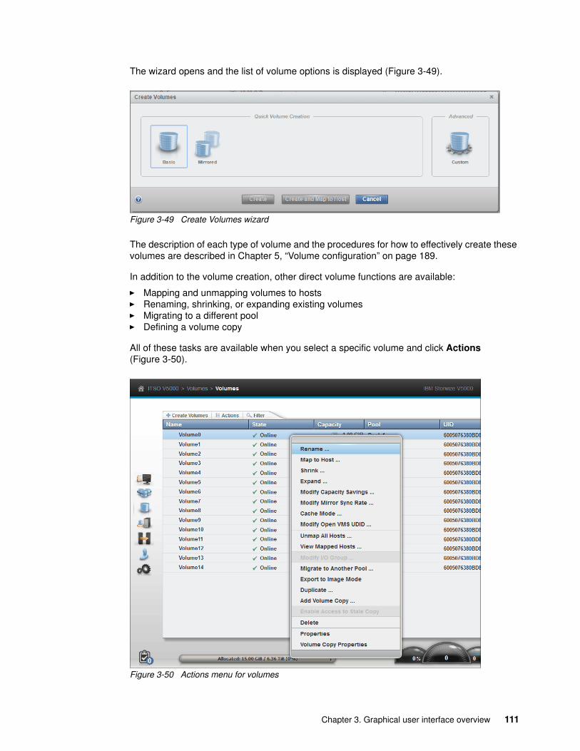
The wizard opens and the list of volume options is displayed (Figure 3-49).
Figure 3-49 Create Volumes wizard
The description of each type of volume and the procedures for how to effectively create these volumes are described in Chapter 5, “Volume configuration” on page 189.
In addition to the volume creation, other direct volume functions are available:
� Mapping and unmapping volumes to hosts� Renaming, shrinking, or expanding existing volumes� Migrating to a different pool� Defining a volume copy
All of these tasks are available when you select a specific volume and click Actions (Figure 3-50).
Figure 3-50 Actions menu for volumes
Chapter 3. Graphical user interface overview 111

When you move a volume to another I/O group (a different Lenovo Storage V5030 system), be sure that the correct host zoning is in place. The target host must have access to both systems: source and target. This function is only available on the Lenovo Storage V5030.
3.5.2 Volumes by pool
This menu is identical to the one that is described in 3.4.3, “Volumes by pool” on page 103. See that section for details.
3.5.3 Volumes by host
Click Volumes by Host to open the window that is shown in Figure 3-51. This window shows the volumes that are mapped to a certain host. You can perform the same actions with volumes as in all previous views, either by clicking Actions or by using the menu that opens after you right-click a specific volume. See Figure 3-51 for details.
Figure 3-51 Listing volumes by host
In addition, you can rename the host by clicking its name and directly typing the new name into the context line (Figure 3-52).
Figure 3-52 Renaming host
Be careful: No confirmation prompt appears. The host is renamed immediately when you click somewhere else or press Enter.
112 Implementing the Lenovo Storage V3700 V2 and V5030 Systems

3.6 Hosts menu
In a SAN environment, host systems are application servers that access data from the storage controllers that are connected to the SAN. Hosts that are running in several operating environments can connect to the storage by using the Lenovo Storage V3700 V2, V3700 V2 XP, and V5030. Host connections to the Lenovo Storage V3700 V2, V3700 V2 XP, and V5030 are either Small Computer System Interface (SCSI) over the FC SAN, Fibre Channel over Ethernet (FCoE) SAN, or Internet Small Computer System Interface (iSCSI) over an Ethernet network.
You can use several tools to manage hosts, including the management GUI, the CLI, and specialized utilities for working with host bus adapters (HBAs). To work with hosts in the management GUI, select Hosts. When you hover the cursor over the Host function icon, the Hosts menu opens, providing the following options (Figure 3-53):
� Hosts� Ports by Host� Host Mappings� Volumes by Host
Figure 3-53 Hosts menu
3.6.1 Hosts
This option provides an overview about all hosts that are connected (zoned) to the system, detected, and configured to be ready for storage allocation. This overview shows the following information about the hosts:
� The name of the host as defined in the management GUI� The type of the host� Its access status� The number of ports that is used for host mapping� Whether host mapping is active
From the same pane, you can create a new host, rename a host, delete a host, or modify a host mapping. The output of the menu selection is shown in Figure 3-54.
Figure 3-54 Overview of configured hosts
Chapter 3. Graphical user interface overview 113

For example, when you click Add Host in a pane header, a wizard opens where you define either a Fibre Channel host or an iSCSI host (Figure 3-55).
Figure 3-55 Add Host wizard
To rename multiple hosts in a single step, mark all hosts that you want by using the Ctrl or Shift key, right-click, and then from the opened menu, select Rename. The window that is shown in Figure 3-56 opens.
Figure 3-56 Renaming multiple hosts
Many of the actions that are described are available from different menus. For example, you can select Volumes and its option Volumes by Hosts, where you can also rename hosts. This flexibility is one of the advantages of the enhanced, redesigned IBM Spectrum Virtualize management GUI.
114 Implementing the Lenovo Storage V3700 V2 and V5030 Systems

3.6.2 Ports by host
Click Ports by Hosts to open the pane that is shown in Figure 3-57. This pane lists the Fibre Channel and iSCSI ports that are assigned to a particular host.
Figure 3-57 Ports by Host window
This overview shows hosts with active, inactive, or degraded ports. You can delete or add a port, or modify its characteristics. Also, in this pane, you can create a new host or rename the existing one.
To perform any of the tasks that are shown in Figure 3-58, click Actions and select a menu item.
Figure 3-58 Available port actions
To delete multiple ports, select them by using the Ctrl key or Shift key and click Delete.
Chapter 3. Graphical user interface overview 115

3.6.3 Host mappings
Click Host Mappings to open the window that is shown in Figure 3-59. It lists the host name, SCSI identifier, volume name, and volume identifier for all mapped volumes.
Figure 3-59 Host mappings
From this window, you can view the host properties. Or, you can obtain the list of mapped volumes or work with port definitions. Right-click the specific host and select Properties (Host) from the opened menu. A window similar to the one in Figure 3-60 opens.
Figure 3-60 Host properties
116 Implementing the Lenovo Storage V3700 V2 and V5030 Systems

With enabled details, you can modify host name, host type, I/O group assignment, or iSCSI Challenge Handshake Authentication Protocol (CHAP) Secret by clicking Edit and then Save, as highlighted in Figure 3-60 on page 116.
3.6.4 Volumes by host
This option is identical to the option that is available in the dynamic menu Volumes. For a description, see 3.5.3, “Volumes by host” on page 112.
3.7 Copy services
The copy services are part of the IBM Replication Family Services, which are available in all IBM Storwize for Lenovo and Lenovo V series family products. It consists of the following functions:
� FlashCopy� Metro Mirror and Global Mirror� Global Mirror with Changed Volumes� Volume Mirroring function (Volume Copy)� Stretched Cluster (formerly Split Cluster) volume mirroring
Figure 3-61 shows the Copy Services menu functions.
Figure 3-61 Copy Services menu
In this section, we briefly describe how to navigate in the Copy Services menu.
3.7.1 FlashCopy
IBM FlashCopy is a function that you use to create a point-in-time copy of one of your volumes. This function might be helpful when you back up a data or test applications. These copies can be cascaded one on another, read from, written to, and even reversed.
Chapter 3. Graphical user interface overview 117

FlashCopy snapshots can conserve storage, if needed, by being space-efficient copies (rather than full copies) that record only items that changed from the originals. Select FlashCopy from the dynamic menu to open a pane similar to the information that is shown in Figure 3-62.
Figure 3-62 FlashCopy operations
If you need to create a FlashCopy of an additional volume, right-click the volume and the list of available functions displays. You can perform several tasks, such as initiate a new snapshot, and clone or back up a volume.
118 Implementing the Lenovo Storage V3700 V2 and V5030 Systems
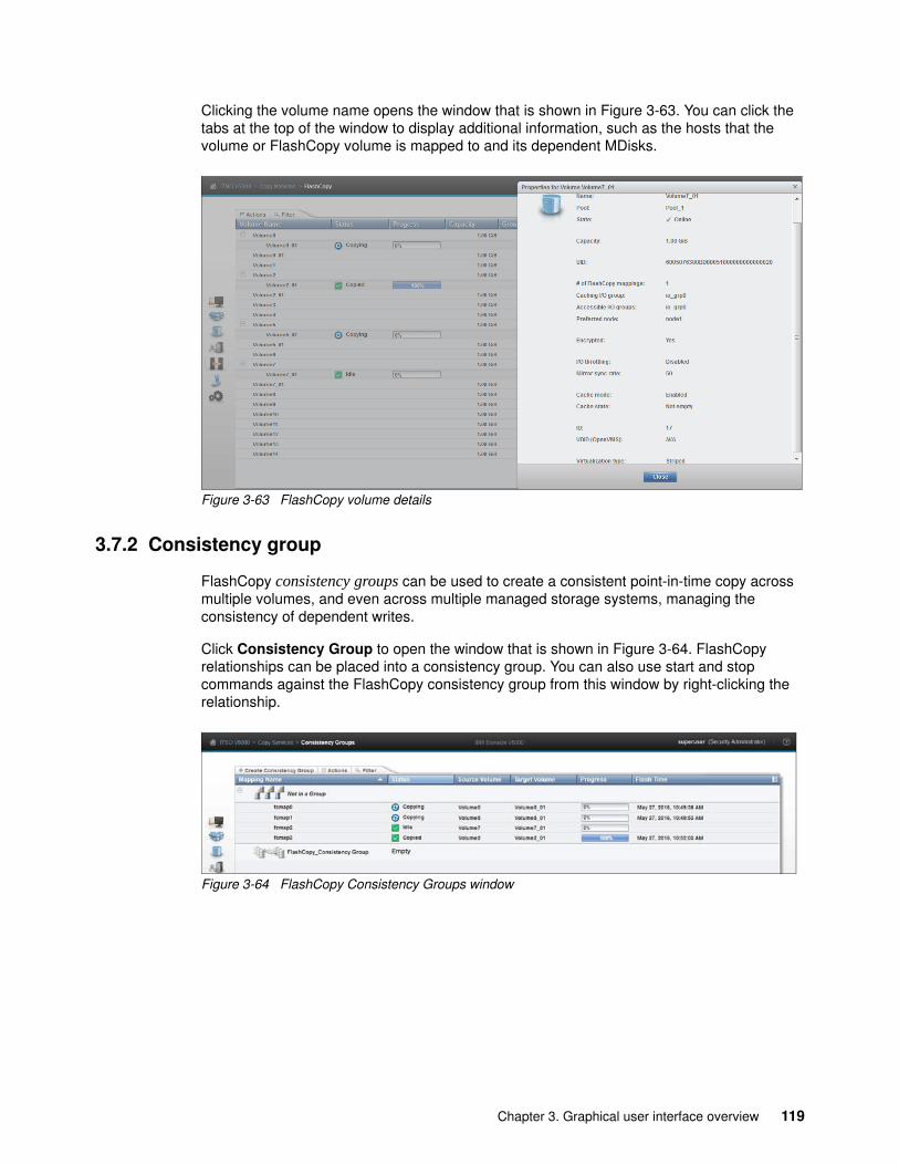
Clicking the volume name opens the window that is shown in Figure 3-63. You can click the tabs at the top of the window to display additional information, such as the hosts that the volume or FlashCopy volume is mapped to and its dependent MDisks.
Figure 3-63 FlashCopy volume details
3.7.2 Consistency group
FlashCopy consistency groups can be used to create a consistent point-in-time copy across multiple volumes, and even across multiple managed storage systems, managing the consistency of dependent writes.
Click Consistency Group to open the window that is shown in Figure 3-64. FlashCopy relationships can be placed into a consistency group. You can also use start and stop commands against the FlashCopy consistency group from this window by right-clicking the relationship.
Figure 3-64 FlashCopy Consistency Groups window
Chapter 3. Graphical user interface overview 119
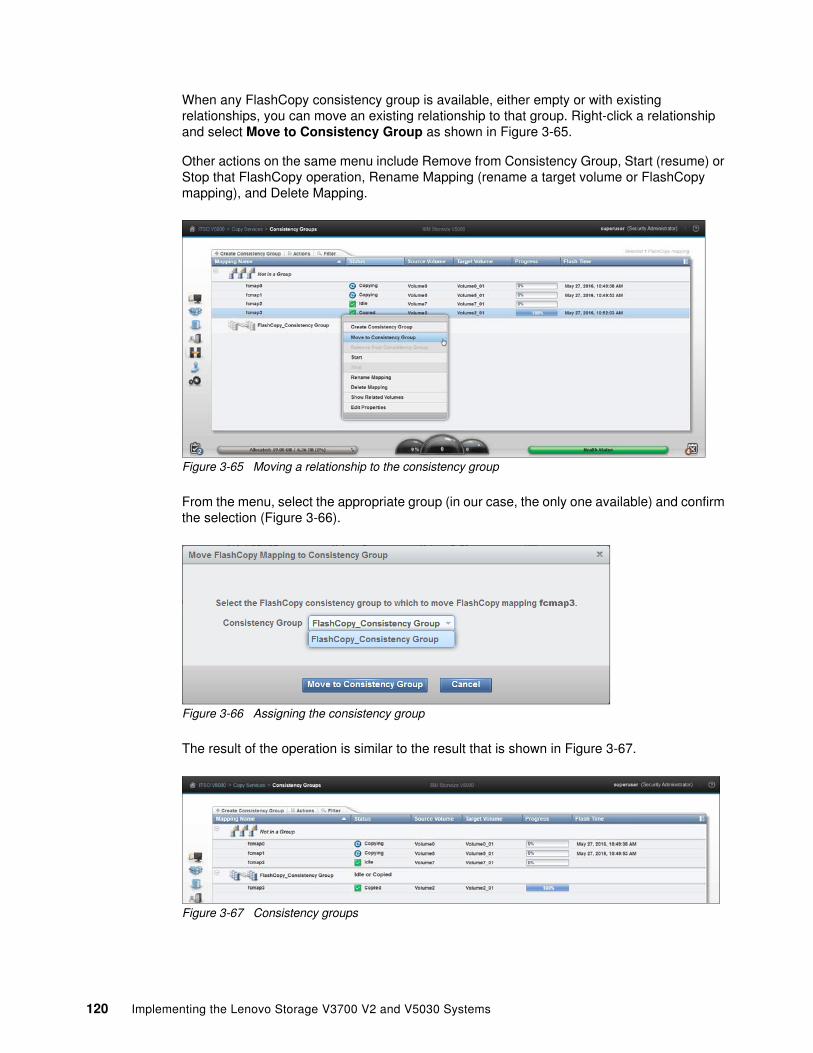
When any FlashCopy consistency group is available, either empty or with existing relationships, you can move an existing relationship to that group. Right-click a relationship and select Move to Consistency Group as shown in Figure 3-65.
Other actions on the same menu include Remove from Consistency Group, Start (resume) or Stop that FlashCopy operation, Rename Mapping (rename a target volume or FlashCopy mapping), and Delete Mapping.
Figure 3-65 Moving a relationship to the consistency group
From the menu, select the appropriate group (in our case, the only one available) and confirm the selection (Figure 3-66).
Figure 3-66 Assigning the consistency group
The result of the operation is similar to the result that is shown in Figure 3-67.
Figure 3-67 Consistency groups
120 Implementing the Lenovo Storage V3700 V2 and V5030 Systems

3.7.3 FlashCopy mappings
To create a new FlashCopy mapping, click Create FlashCopy Mapping (shown in Figure 3-68) to start a wizard. This wizard maps a source volume to a target volume to prepare for a subsequent copy. This mapping persists until it is deleted. The mapping specifies the source and destination volumes. The destination must be identical in size to the source or the mapping fails.
Figure 3-68 FlashCopy mappings
In a single mapping, the source and destination cannot be on the same volume. A mapping is triggered at the point in time when the copy is required. The mapping can optionally be given a name and assigned to a consistency group. These groups of mappings can be triggered at the same time, enabling multiple volumes to be copied at the same time, which creates a consistent copy of multiple disks. A consistent copy of multiple disks is required for database products in which the database and log files are on separate disks.
If a consistency group (ID or Name) is not specified, the mapping is assigned to the default group 0, which is a special group that cannot be started as a whole. Mappings in this group can be started only on an individual basis.
Chapter 3. Graphical user interface overview 121

An example of the wizard for FlashCopy mapping creation is shown in Figure 3-69. Select source and target volumes from the wizard.
Figure 3-69 Selecting volumes for FlashCopy mappings
You can select the Snapshot (copy-on-write), Clone (replica of the volume without effect on original one), or Backup (data recovery) type of relationship. When selected, you can specify whether you also want to add the mapping to the consistency group.
3.7.4 Remote copy
Click Remote Copy to open the window that is shown in Figure 3-70. This window shows the existing remote copy relationships, and you can set up and modify consistency groups. From this window, you can also start and stop relationships, add relationships to a consistency group, and switch the direction of the mirror.
Figure 3-70 Remote Copy window
122 Implementing the Lenovo Storage V3700 V2 and V5030 Systems

The menu provides the options to create Metro Mirror, Global Mirror, or Global Mirror with Changed Volumes:
Metro Mirror This option makes synchronous copies. The original write operations are not considered complete until the write operation to the destination disk is confirmed. The distance between your two sites is determined by how much latency your applications can handle.
Global Mirror This option makes asynchronous copies of your disk. The write is considered complete after it is complete at the local disk. It does not wait for the write to be confirmed at the remote cluster as Metro Mirror does. This method greatly reduces the latency that is experienced by your applications if the other cluster is far away. However, it also means that during a failure, the data on the remote copy might not contain the most recent changes that were committed to the local disk.
Global Mirror with Changed Volumes
This option is best described as “Continuous Remote FlashCopy.” If you use this feature, IBM Spectrum Virtualize essentially takes a periodic FlashCopy of a disk and writes it to your remote destination. This feature completely isolates the local copy from wide area network (WAN) issues and from sudden spikes in workload that might occur. The drawback is that your remote copy might lag behind the original by a significant amount of data, depending on how you set up the cycle time.
3.7.5 Partnerships
Click Partnerships to open the window that is shown in Figure 3-71. You can use this window to set up a new partnership, or delete an existing partnership for remote mirroring with another Lenovo Storage V3700 V2, V3700 V2 XP, and V5030 systems. To create a partnership, click Create Partnership. A new window displays. When you select the partnership type, for example, Fibre Channel, the window expands to a more detailed view, as shown in Figure 3-71.
Figure 3-71 Creating a partnership
Chapter 3. Graphical user interface overview 123

Clicking an existing partnership opens a window, as shown in Figure 3-72. From this window, you can also set the background copy rate. This rate specifies the bandwidth, in Mbps, that is used by the background copy process between the clusters (Figure 3-72). In our case, we configured the partnership only on one side. You can see it in the State row. It shows Partially Configured: Local, which is an indication that the configuration was only configured on one side. If you see this message, go to the second system, and configure the Create Partnership settings there, too.
Figure 3-72 Partnership properties
3.8 Access menu
The Access menu has two options:
� Users (for user management)� Audit Log
Figure 3-73 shows these options.
Figure 3-73 Access menu
124 Implementing the Lenovo Storage V3700 V2 and V5030 Systems

3.8.1 Users
Figure 3-74 shows the Users pane. You can create and delete new users, change and remove passwords, and add and remove Secure Shell (SSH) keys.
Figure 3-74 Users window
Click Create User to open the pane that is shown in Figure 3-75. Use this pane to specify the name and password of the user, and load the SSH key (if the SSH key was generated).
Figure 3-75 Adding a user
Chapter 3. Graphical user interface overview 125

3.8.2 Audit Log option
Click Audit Log to open the window that is shown in Figure 3-76. The cluster maintains an audit log of successfully run commands and displays the users that performed particular actions at certain times.
Figure 3-76 Audit Log entries
126 Implementing the Lenovo Storage V3700 V2 and V5030 Systems

You can filter audit log records by date or within a specific time frame (Figure 3-77).
Figure 3-77 Filtering the records
The following commands are not recorded in the audit log:
� All commands that failed � dumpconfig � cpdumps � cleardumps � finderr � dumperrlog � dumpinternallog � svcservicetask dumperrlog � svcservicetask finderr
Chapter 3. Graphical user interface overview 127

3.9 Settings menu
The Settings menu provides various options to adjust your system parameters according to your needs. You can configure these options (Figure 3-78):
� Notifications� Network� Security (remote authentication)� System� Support� GUI Preferences
Figure 3-78 Settings menu
3.9.1 Notifications
It is important to correct any issues that are reported by your IBM Spectrum Virtualize system as soon as possible. Configure your system to send automatic notifications when a new event is reported. To avoid monitoring for new events that use the management GUI, select the type of event that you want to be notified about, for example, restrict notifications to events that require immediate action.
You can use email, Simple Network Management Protocol (SNMP), or syslog types of notifications. If your system is within warranty, or if you use a hardware maintenance agreement, configure your Lenovo Storage V3700 V2, V3700 V2 XP, and V5030 systems to send email events to IBM directly if an issue that requires hardware replacement is detected. This mechanism is called Call Home.
128 Implementing the Lenovo Storage V3700 V2 and V5030 Systems

When an event is received, IBM automatically opens a problem report. If appropriate, IBM contacts you to verify whether replacement parts are required. The configuration window for email notifications is shown in Figure 3-79.
Figure 3-79 Email event notifications
The procedure for how to enable email notifications is described in Chapter 12, “RAS, monitoring, and troubleshooting” on page 575.
3.9.2 Network
Click Network to open the window that is shown in Figure 3-80. You can update the network configuration, set up iSCSI definitions, and view information about the Fibre Channel connections.
Figure 3-80 Network window
Chapter 3. Graphical user interface overview 129

When you click Fibre Channel Connectivity (Figure 3-81), useful information is displayed. In this example, we click All nodes, storage systems, and hosts from the menu and then select Show Results to display the details. Other options that are available from the menu include displaying Fibre Channel details for a host, clusters, nodes, or storage systems.
Figure 3-81 Fibre Channel connectivity
3.9.3 Security
The security features are described.
Remote authenticationWith security and its directory services, the user can remotely authenticate to the controller firmware without the need for a local account. Therefore, when you log on, you authenticate with your domain user ID and password rather than a locally created user ID and password.
The benefits of remote authentication are listed:
� You do not need to configure every user on every machine. If multiple machines are in your environment, you can set up authentication more efficiently.
� When commands are run on the controller firmware, the audit log shows the domain user name that issued that command, rather than a local user name, or worse, just “superuser”. (In this case, determining who mapped a volume, acted as the superuser, and so on might be difficult.)
� You have central control over access. If someone leaves the company, you simply remove access at the domain controller, which means that orphan accounts do not remain on your storage equipment.
130 Implementing the Lenovo Storage V3700 V2 and V5030 Systems

The access pane to configure remote authentication is shown in Figure 3-82.
Figure 3-82 Configuring remote authentication
The detailed steps to configure remote logon are described at the following addresses:
� http://ibm.biz/Bd4Cr5 � https://ibm.biz/Bd4Csc
EncryptionOn the panel that is shown in Figure 3-83, you can enable or disable the encryption function on an Lenovo Storage V5030. The panel shows that no USB drives that contain encryption keys were detected. If the system needs to restart, you cannot access your encrypted data.
Figure 3-83 Encryption panel
Secure communicationsUse the Secure Communications page to enable and manage secure connections. During system setup, an initial certificate is created to use for secure connections between web browsers. Based on the security requirements for your system, you can create either a new self-signed certificate or install a signed certificate that is created by a third-party certificate authority.
Chapter 3. Graphical user interface overview 131

Self-signed certificates are generated automatically by the system and encrypt communications between the browser and the system. Self-signed certificates can generate web browser security warnings, and they might not comply with organizational security guidelines. Signed certificates are created by a third-party certificate authority. These certificate authorities ensure that certificates have the required security level for an organization based on purchase agreements. Signed certificates usually have higher security controls for the encryption of data and do not cause browser security warnings.
To use a signed certificate, first generate and download a request for a certificate that is based on the values that are specified on the Secure Communication page. Submit this request to the certificate authority to receive a signed certificate and then install it by using the Secure Communication page. Before you create a request for either type of certificate, ensure that your current browser does not restrict the type of keys that are used for certificates. Certain browsers limit the use of specific key types for security and compatibility.
On Figure 3-84, you can see the details about the security certificates.
Figure 3-84 Secure communications
If you want to update or change the certificate, click Update Certificate.
132 Implementing the Lenovo Storage V3700 V2 and V5030 Systems

The Update Certificate panel opens, as shown in Figure 3-85.
Figure 3-85 Update Certificate panel
3.9.4 System
The System menu provides four options:
� Set the system date and time� Manage licenses� Upgrade software� Virtual Volumes (VVols)
The Date and Time window opens (Figure 3-86) when you select Date and Time from the System menu. You can add a Network Time Protocol (NTP) server if available.
Figure 3-86 Date and Time window
Chapter 3. Graphical user interface overview 133

You can also update the license information for specific features, as shown in Figure 3-87.
Figure 3-87 Licensing options
To upgrade your system, use the procedure that is described in Chapter 12, “RAS, monitoring, and troubleshooting” on page 575.
Virtual Volume (VVol) is a tape volume that resides in a tape volume cache of a virtual tape server (VTS). VVol is a new feature that was introduced in controller firmware 7.6. With this new functionality, users can create volumes directly from a VMware VCenter server.
On the VVOL page, you can enable or disable the functionality, as shown in Figure 3-88. Before you can enable VVol, you must set up an NTP server. See the Date and Time settings to set up the NTP server.
Figure 3-88 Activating VVol
134 Implementing the Lenovo Storage V3700 V2 and V5030 Systems

3.9.5 Support
The Support window provides access to features that help Lenovo to analyze the critical and uncertain issues with the system based on downloaded and provided support packages. Figure 3-89 shows how to download support logs.
Figure 3-89 Downloading support packages
For more information, see Chapter 12, “RAS, monitoring, and troubleshooting” on page 575.
Chapter 3. Graphical user interface overview 135

3.9.6 GUI preferences
By using this menu, you can configure the appearance and behavior of the GUI. Click GUI Preferences in the Settings option of the Dynamic menu. The layout of the dialog window and available options are shown in Figure 3-90.
Figure 3-90 GUI preferences
To display the login message, select Enable. You can create a customized login message as shown in Figure 3-91.
Figure 3-91 Login Message window
136 Implementing the Lenovo Storage V3700 V2 and V5030 Systems

Select General to adjust the browser settings. See Figure 3-92.
Figure 3-92 General settings
Chapter 3. Graphical user interface overview 137

138 Implementing the Lenovo Storage V3700 V2 and V5030 Systems

Chapter 4. Host configuration
This chapter describes how to use the Lenovo Storage V3700 V2, V3700 V2 XP, and V5030 graphical user interface (GUI) to create hosts and how to prepare a host to access the volumes that are created. (Volume creation is described in Chapter 5, “Volume configuration” on page 189.)
This chapter includes the following topics:
� 4.1, “Host attachment overview” on page 140� 4.2, “Planning for direct-attached hosts” on page 141� 4.3, “Preparing the host operating system” on page 142� 4.4, “Creating hosts by using the GUI” on page 168
4
© Copyright Lenovo 2018. All rights reserved. 139

4.1 Host attachment overview
A host system is an open-systems computer that is connected to the switch through a Fibre Channel (FC), direct-attached, serial-attached SCSI (SAS) connection or an Internet Small Computer System Interface (iSCSI).
The Lenovo Storage V3700 V2, V3700 V2 XP, and V5030 support the following host attachment protocols:
� 16 Gb FC or 10 Gb iSCSI/FC over Ethernet (FCoE) as an optional host interface� 12 Gb SAS (standard host interface)� 1 Gb or 10 Gb iSCSI (standard host interface, depending on the model)
This chapter describes the following topics:
� Prepare the host operating system:
– Microsoft Windows:
• FC• iSCSI• SAS
– VMware:
• FC• iSCSI• SAS
� Create hosts by using the Lenovo Storage V3700 V2, V3700 V2 XP, and V5030 GUI:
– Creating FC hosts– Creating iSCSI hosts– Creating SAS hosts
In this chapter, we assume that your hosts are connected to your FC, SAS, or Internet Protocol (IP) network and you completed the steps that are described in Chapter 2, “Initial configuration” on page 33. Follow basic zoning recommendations to ensure that each host has at least two network adapters, that each adapter is on a separate network (or at minimum in a separate zone), and that each adapter is connected to both canisters. This setup ensures four paths for failover and failback.
For SAS attachment, ensure that each host has at least one SAS host bus adapter (HBA) connection to each Lenovo Storage V3700 V2, V3700 V2 XP, and V5030 canister. Further information about configuring SAS attached hosts is provided in 2.4, “SAS direct-attach planning” on page 43.
Before you map the newly created volumes on the host of your choice, preparation goes a long way toward ease of use and reliability. Several steps are required on a host in preparation for mapping new Lenovo Storage V3700 V2, V3700 V2 XP, and V5030 volumes to the host. Use the Lenovo Storage matrix shows to check the code levels that are supported to attach your host to your storage. The SSIC is a web tool that checks the interoperation of host, storage, switches, and multipathing drivers. The interoperability matrix can be obtained at the following addresses:
https://datacentersupport.lenovo.com/tw/en/products/storage/lenovo-storage/v3700v2/6535/documentation
https://datacentersupport.lenovo.com/tw/en/products/storage/lenovo-storage/v5030/6536/documentation
140 Implementing the Lenovo Storage V3700 V2 and V5030 Systems

This chapter focuses on Windows and VMware. If you want to attach any other hosts, for example, IBM AIX, Linux, or an Apple system, you can find the required information at the following address:
http://systemx.lenovofiles.com/mobile/help/topic/com.lenovo.storage.v3700.doc/lenovo_vseries.html
4.2 Planning for direct-attached hosts
Starting with V7.5, we supported direct-attached Fibre Channel hosts. A direct-attached configuration dedicates the entire port bandwidth for use for a specific connection. Planning must account for the volume of expected traffic before you decide how many ports are used in a direct-attached configuration. The Lenovo Storage V3700 V2, V3700 V2 XP, and V5030 systems offers multiple options for you to decide how to create a direct-attached configuration.
Because of the bandwidth requirements when you use a direct-attached configuration, it is important to determine the volume of expected traffic when you decide the number of required ports. For example, if a Lenovo Storage V5030 to Lenovo Storage V5030 direct-attached link is configured between nodes, the link might carry intra-node traffic, such as FlashCopy data. Therefore, enough Lenovo Storage V5030 to Lenovo Storage V5030 bandwidth needs to be available so that it can carry all possible intra-node traffic without any bandwidth bottleneck.
The following guidelines are provided for direct-attached configurations.
4.2.1 Fibre Channel direct attachment to host systems
The Lenovo Storage V3700 V2, V3700 V2 XP, and V5030 support direct attachment connectivity between its FC ports and host ports. Host systems can connect to 16 Gb FC ports on the Lenovo Storage V3700 V2, V3700 V2 XP, and V5030. No special configuration is required for host systems that use this configuration.
4.2.2 FC direct attachment between nodes
Direct connection of the Lenovo Storage V3700 V2, V3700 V2 XP, and V5030 FC ports without using an FC switch is supported. Such connections between the Lenovo Storage V3700 V2, V3700 V2 XP, and V5030 nodes might be useful in small configurations where no FC switch exists. It can also be used to connect nodes in the same input/output (I/O) group to provide a dedicated connection for mirroring the fast write cache data. Ensure that sufficient bandwidth is provisioned between nodes to accommodate all of the intra-node traffic.
The Lenovo Storage V3700 V2, V3700 V2 XP, and V5030 support 16 Gb Fibre Channel ports and support Fibre Channel direct attachment on all 16 Gb ports.
Note: Be careful about the maximum length of the Fibre Channel links in this configuration.
Chapter 4. Host configuration 141

4.3 Preparing the host operating system
The following steps are required to prepare a host to connect to the Lenovo Storage V3700 V2, V3700 V2 XP, and V5030:
1. Ensure that the latest supported system updates are applied to your host operating system.
2. Ensure that the HBAs are physically installed in the host.
3. Ensure that the latest supported HBA firmware and driver levels are installed in your host.
4. Configure the HBA parameters. Although settings are provided for each host OS in the following sections, review the Lenovo Storage V3700 V2, V3700 V2 XP, and V5030 Lenovo Information Center to obtain the latest supported settings.
5. Configure the host I/O parameters, such as the disk I/O timeout value.
6. Install and configure multipath software.
7. Determine the host worldwide port names (WWPNs).
8. Connect the HBA ports to switches by using the correct cables, or directly attach to the ports on the Lenovo Storage V3700 V2, V3700 V2 XP, and V5030.
9. Configure the switches, if applicable.
10.Optional: Configure SAN Boot.
4.3.1 Windows 2008 R2 and 2012 R2: Preparing for Fibre Channel attachment
Complete the following steps to prepare a Windows 2008 R2 or Windows 2012 R2 host to connect to an Lenovo Storage V3700 V2, V3700 V2 XP, and V5030 by using Fibre Channel:
1. Ensure that the current O/S service pack and test fixes are applied to your server.
2. Use the current firmware and driver levels on your host system.
3. Install a host bus adapter (HBA) or HBAs on the Windows server by using the current basic input/output system (BIOS) and drivers.
4. Connect the FC host adapter ports to the switches, or use direct connections.
5. Configure the switches (zoning).
6. Configure the HBA for hosts that run Windows.
7. Set the Windows timeout value.
8. Install the multipath module.
Downloading and installing the supported drivers and firmwareInstall a supported HBA driver for your configuration. Use the Windows Device Manager or vendor tools, such as QLogic Converged Console (QCC) or HBAnyware (Emulex), to install the driver. Brocade adapter software is now maintained by QLogic, so check the QLogic web pages to obtain the correct support for your Brocade adapters. Also, check and update the BIOS (firmware) level of the HBA by using the manufacturer’s provided tools. Check the readme file to see whether any Windows registry parameters must be set for the HBA driver.
You can obtain the current supported levels by navigating from the following address:
https://ibm.biz/BdHKW8
142 Implementing the Lenovo Storage V3700 V2 and V5030 Systems

Configuring Brocade HBAs for WindowsThis section applies to Windows hosts with installed Brocade HBAs. After you install the device driver and firmware, you must configure the HBAs. To perform this task, either use the Brocade Host Connectivity Manager (HCM) software or restart into the HBA BIOS, load the adapter defaults, and set the following values:
� Host Adapter BIOS: Disabled (unless the host is configured for storage area network (SAN) Boot)
� Queue depth: 4
Configuring QLogic HBAs for WindowsThis section applies to Windows hosts with installed QLogic HBAs.
After you install the device driver and firmware, you must configure the HBAs. To perform this task, either use the QLogic QConverge Console (QCC) command-line interface (CLI) software or restart into the HBA BIOS, load the adapter defaults, and set the following values:
� Host Adapter BIOS: Disabled (unless the host is configured for SAN Boot)� Adapter Hard Loop ID: Disabled� Connection Options: 1 (only point to point)� Logical unit numbers (LUNs) Per Target: 0� Port Down Retry Count: 15
The QCC Control Center Software is at this website:
https://ibm.biz/BdHjUg
Configuring Emulex HBAs for WindowsThis section applies to Windows hosts with installed Emulex HBAs.
After you install the device driver and firmware, you must configure the HBAs. To perform this task, either use the Emulex HBAnyware software or restart into the HBA BIOS, load the defaults, and set topology to 1 (10F_Port Fabric).
Setting the Windows timeout valueFor Windows hosts, the disk I/O timeout value needs to be set to 60 seconds. To verify this setting, complete the following steps:
1. Click Start → Run. Alternatively, open a Power Shell window.
2. In the dialog box or Power Shell window, type regedit and press Enter.
3. In the registry editor, locate the HKEY_LOCAL_MACHINE\System\CurrentControlSet\Services\disk\TimeOutValue key.
4. Confirm that the value for the key is 60 (decimal value), and, if not, change the value to 60 (Figure 4-1).
Figure 4-1 Windows timeout value
Installing the multipathing softwareMicrosoft Multipath Input/Output (MPIO) solutions work with device-specific modules (DSMs) that are written by vendors, but the MPIO driver package does not, by itself, form a complete solution. This joint solution enables the storage vendors to design device-specific solutions that are tightly integrated with the Windows operating system. MPIO is not included with the Windows operating system. Storage vendors must pack the MPIO drivers with their own DSM.
Chapter 4. Host configuration 143

Lenovo Subsystem Device Driver DSM (SDDDSM) is the Lenovo multipath I/O solution that is based on Microsoft MPIO technology. It is a device-specific module that supports Lenovo storage devices on Windows hosts. The intent of MPIO is to provide better integration of a multipath storage solution with the operating system, and it supports the use of multipath in the SAN infrastructure during the startup process for SAN Boot hosts.
To ensure correct multipathing with the Lenovo Storage V3700 V2, V3700 V2 XP, and V5030, SDDDSM must be installed on Windows hosts. To install SDDDSM, complete the following steps:
1. Go to the following SDDDSM download matrix to determine the correct level of SDDDSM to install for Windows 2008 R2 or Windows 2012 R2, and then download the package:
http://systemx.lenovofiles.com/help/topic/com.lenovo.storage.v3700.doc/svc_w2kmultipathovr_21osvf.html
2. Extract the package to your hard disk drive, and run setup.exe to install SDDDSM. A command prompt window opens (Figure 4-2). Confirm the installation by entering Yes.
Figure 4-2 SDDDSM setup
3. During the setup, SDDDSM also determines whether an older version is installed and prompts you to upgrade to the current version.
4. After the setup completes, you are prompted to restart the system. Confirm this restart by typing Yes and pressing Enter (Figure 4-3).
Figure 4-3 Answer Yes to restart the host
You successfully installed Lenovo SDDDSM. To check whether Lenovo SDDDSM is installed correctly, see the following sections about Windows 2008 R2 and Windows 2012 R2.
Windows 2008 R2To check the installed driver version, complete the following steps:
1. Select Start → All Programs → Subsystem Device Driver DSM → Subsystem Device Driver DSM.
2. A command prompt opens. Run datapath query version to determine the version that is installed (Example 4-1 on page 145) for this Windows 2008 R2 host.
144 Implementing the Lenovo Storage V3700 V2 and V5030 Systems

Example 4-1 The datapath query version command
C:\Program Files\IBM\SDDDSM>datapath query versionIBM SDDDSM Version 2.4.5.1Microsoft MPIO Version 6.1.7601.17514
3. The worldwide port names (WWPNs) of the FC HBA are required to correctly zone switches and configure host attachment on the Lenovo Storage V3700 V2, V3700 V2 XP, and V5030. You can obtain the WWPNS by using vendor tools, the HBA BIOS, the native Windows command line, or SDDDSM. This command can be used to determine the worldwide port names (WWPNs) of the host. Run datapath query wwpn (Example 4-2) and note the WWPNs of your host because you need them later.
Example 4-2 The datapath query wwpn command
C:\Program Files\IBM\SDDDSM>datapath query wwpn Adapter Name PortWWN
Scsi Port3: 21000024FF35B960Scsi Port4: 21000024FF25B961
If you need more detailed information about SDDDSM, see Multipath Subsystem Device Driver User’s Guide, GC52-1309. The guide is available at this website:
http://www.ibm.com/support/docview.wss?uid=ssg1S7000303
Chapter 4. Host configuration 145

Windows 2012 R2To check the installed driver version, complete the following steps:
1. First, select the Windows Start icon in the lower-left corner. See Figure 4-4.
Figure 4-4 Windows 2012 R2 start
2. Expand the view by clicking the down arrow that is shown in Figure 4-5.
Figure 4-5 Expand view to see all programs that are installed
146 Implementing the Lenovo Storage V3700 V2 and V5030 Systems

3. Search for the section Subsystem Device Driver DSM. See Figure 4-6.
Figure 4-6 Subsystem Device Driver DSM in the all programs menu
4. Click Subsystem Device Driver DSM. See Figure 4-7.
Figure 4-7 Subsystem Device Driver DSM
5. A command prompt opens. Run datapath query version to determine the version that is installed. See Figure 4-8.
Figure 4-8 Datapath query version
6. See Example 4-3 for the Windows 2012 R2 host.
Example 4-3 The datapath query version command
C:\Program Files\IBM\SDDDSM>datapath query versionIBM SDDDSM Version 2.4.5.1Microsoft MPIO Version 6.3.9600.16384C:\ProgramFiles\IBM\SDDDSM>
7. The WWPNs of the FC HBA are required to correctly zone switches and configure host attachment on the Lenovo Storage V3700 V2, V3700 V2 XP, and V5030. You can obtain the WWPNs by using vendor tools, the HBA BIOS, the native Windows command line, or SDDDSM. This command can be used to determine the WWPNs of the host. Run datapath query wwpn (Example 4-4) and document the WWPNs of your host because you need them later.
Example 4-4 The datapath query wwpn command
C:\Program Files\IBM\SDDDSM>datapath query wwpn Adapter Name PortWWN Scsi Port 7 100000051EC76B89 Scsi Port 7 100000051EC76B8A
Chapter 4. Host configuration 147

If you need more detailed information about SDDDSM, see Multipath Subsystem Device Driver User’s Guide, GC52-1309. A PDF version of the Multipath Subsystem Device Driver User’s Guide, GC52-1309, is at the following website:
https://ibm.biz/BdEqeZ
The Windows host was prepared to connect to the Lenovo Storage V3700 V2, V3700 V2 XP, and V5030, and you know the WWPNs of the host. The next step is to configure a host object for the WWPNs by using the Lenovo Storage V3700 V2, V3700 V2 XP, and V5030 GUI. This task is explained in 4.4.1, “Creating Fibre Channel hosts” on page 170.
SAN Boot hosts are beyond the intended scope of this book. For more information about that topic, search for SAN Boot on the following website:
http://systemx.lenovofiles.com/help/topic/com.lenovo.storage.v3700.doc/lenovo_vseries.html
4.3.2 Windows 2008 R2 and Windows 2012 R2: Preparing for iSCSI attachment
This section details iSCSI attachment.
Installing and updating supported HBAsInstall a supported HBA model with the latest supported firmware and drivers for your configuration. The latest supported HBAs and levels for Windows 2008 R2 and 2012 R2 are available at interoperability matrix in the following websites:
https://datacentersupport.lenovo.com/tw/en/products/storage/lenovo-storage/v3700v2/6535/documentation
https://datacentersupport.lenovo.com/tw/en/products/storage/lenovo-storage/v5030/6536/documentation
Install the driver by using Windows Device Manager or vendor tools. Also, check and update the firmware level of the HBA by using the manufacturer’s provided tools. Always check the readme file to see whether any Windows registry parameters must be set for the HBA driver.
If you use a hardware iSCSI HBA, refer to the manufacturer’s documentation and the Lenovo Storage V3700 V2, V3700 V2 XP, and V5030 Lenovo Information Center for further details and the latest information about the hardware and host OS configuration. The following section describes how to configure iSCSI by using the software initiator.
In Windows 2008 R2 and 2012, the Microsoft iSCSI software initiator is preinstalled.
Windows 2003: The examples focus on Windows 2008 R2 and Windows 2012, but the procedure for Windows 2003 is similar. If you use Windows 2003, do not forget to install Microsoft hotfix 908980. If you do not install it before you perform this procedure, preferred pathing is not available. You can download this hotfix from the following address:
http://support.microsoft.com/kb/908980
Important: For converged network adapters (CNAs), which can support both FC and iSCSI, it is important to ensure that the Ethernet networking driver is installed in addition to the FCoE driver. You are required to install the Ethernet networking driver and the FCoE driver before you configure iSCSI.
148 Implementing the Lenovo Storage V3700 V2 and V5030 Systems

Complete the following steps:
1. Enter iscsi in the search field of the Windows 2008 R2 Start window (Figure 4-9) and click iSCSI Initiator.
Figure 4-9 Windows 2008 R2 iSCSI Initiator
2. For Windows 2012 R2, go to the all programs menu and enter iSCSI in the search field at the top of the window. See Figure 4-10.
Figure 4-10 iSCSI Initiator Windows 2012 R2
3. Confirm the automatic start of the iSCSI service (Figure 4-11).
Figure 4-11 Automatic start of the iSCSI service
Chapter 4. Host configuration 149

4. The iSCSI Initiator Properties window opens. Select the Configuration tab (Figure 4-12). Write down the initiator name of your Windows host because you use it later.
Figure 4-12 iSCSI Initiator Properties window
5. You can change the initiator name, or enable advanced authentication, but these actions are out of the scope of our basic setup. By default, iSCSI authentication is not enabled. More details are available at the Lenovo Information Center for the Lenovo Storage V3700 V2, V3700 V2 XP, and V5030 at the following address:
http://systemx.lenovofiles.com/help/topic/com.lenovo.storage.v3700.doc/lenovo_vseries.html
6. From the Configuration tab, you can change the initiator name, enable CHAP authentication, and more. However, these tasks are beyond the scope of our basic setup. CHAP authentication is disabled, by default. For more information, see the Microsoft iSCSI Initiator Step-by-Step Guide:
http://technet.microsoft.com/en-us/library/ee338476%28v=ws.10%29.aspx
150 Implementing the Lenovo Storage V3700 V2 and V5030 Systems

Configuring Ethernet portsWe suggest that you use separate dedicated ports for host management and iSCSI. In this case, we need to configure IPs on the iSCSI ports in the same subnet and virtual LAN (VLAN) as the external storage that we want to attach to.
To configure Ethernet port IPs on Windows 2008 R2 and 2012 R2, complete the following steps:
1. Go to Control Panel → Network and Internet → Network and Sharing Center. The window that is shown in Figure 4-13 opens.
Figure 4-13 Network and Sharing Center in Windows 2012 R2
In this case, two networks are visible to the system. We use the first network to connect to the server. It consists of a single dedicated Ethernet port for management. The second network is our iSCSI network. It consists of two dedicated Ethernet ports for iSCSI. We suggest that you use at least two dedicated ports for failover purposes.
Chapter 4. Host configuration 151

2. To configure an IP address, click one of the iSCSI Ethernet connections (in this case, Ethernet 3 or Ethernet 4). Figure 4-14 shows the window that displays the Ethernet status.
Figure 4-14 Ethernet status
3. To configure the IP address, click Properties (Figure 4-15).
Figure 4-15 Ethernet properties
152 Implementing the Lenovo Storage V3700 V2 and V5030 Systems

4. If you use IPv6, select Internet Protocol Version 6 (TCP/IPv6) and click Properties. Otherwise, select Internet Protocol Version 4 (TCP/IPv4) and click Properties to configure an IPv4 address.
5. For IPv4, the window that is shown in Figure 4-16 opens. To manually set the IP, select “Use the following address” and enter an IP address, subnet mask, and gateway. Set the DNS server address, if required. Click OK to confirm.
Figure 4-16 Configuring an IPv4 address in Windows 2012 R2
6. Repeat the previous steps for each port that you want to configure for iSCSI attachment.
The Ethernet ports are now prepared for iSCSI attachment.
Setting the Windows registry keysModify the system registry so that your iSCSI operations are more reliable:
1. In the search field of the Windows Start window, type regedit and click regedit.exe.
2. In the registry editor, locate the following key:
HKEY_LOCAL_MACHINE\SYSTEM\CurrentControlSet\Control\Class\{4D36E97B-E325-11CE-BFC1-08002BE10318}\<bus ID>\Parameters\LinkDownTime
Confirm that the value for the LinkDownTime key is 120 (decimal value) and, if not, change the value to 120.
3. In the registry editor, locate the following key:
HKEY_LOCAL_MACHINE\SYSTEM\CurrentControlSet\Control\Class\{4D36E97B-E325-11CE-BFC1-08002BE10318}\<bus ID>\Parameters\MaxRequestHoldTime
Confirm that the value for the MaxRequestHoldTime key is 120 (decimal value) and, if not, change the value to 120.
Chapter 4. Host configuration 153

4. In the registry editor, locate the following key:
HKEY_LOCAL_MACHINE\SYSTEM\CurrentControlSet\Control\Class\{4D36E97B-E325-11CE-BFC1-08002BE10318}\<bus ID>\Parameters\MaxPendingRequests
Confirm that the value for the MaxPendingRequests key is 2048 (decimal value) and, if not, change the value to 2048.
5. In the registry editor, locate the following key:
HKEY_LOCAL_MACHINE\SYSTEM\CurrentControlSet\Services\Disk\TimeOutValue
Confirm that the value for the TimeOutValue key is 60 (decimal value) and, if not, change the value to 60.
6. Restart your host for these changes to take effect.
Multipath support for iSCSI on WindowsFor multipathing with iSCSI, we need to enable Microsoft Multipath Input/Output (MPIO). See “Installing the multipathing software” on page 143 for instructions to enable MPIO.
These basic steps are to prepare a Windows 2008 R2 or Windows 2012 R2 host for iSCSI attachment. To configure the Lenovo Storage V3700 V2, V3700 V2 XP, and V5030 for iSCSI connections, see 4.4.3, “Creating iSCSI hosts” on page 178.
4.3.3 Windows 2012 R2: Preparing for SAS attachment
This procedure is described in the following sections.
Installing and updating supported HBAsInstall a supported SAS HBA with the latest supported firmware and drivers for your configuration. A list of the latest supported HBAs and levels for Windows 2008 R2 and Windows 2012 R2 is available at interoperability matrix of the following website:
https://datacentersupport.lenovo.com/tw/en/products/storage/lenovo-storage/v3700v2/6535/documentation
https://datacentersupport.lenovo.com/tw/en/products/storage/lenovo-storage/v5030/6536/documentation
Install the driver by using Windows Device Manager or vendor tools. Also, check and update the firmware level of the HBA by using the manufacturer’s provided tools. Always check the readme file to see whether any Windows registry parameters must be set for the HBA driver.
For LSI cards, the following website provides guidance about flashing the HBA firmware and BIOS:
http://mycusthelp.info/LSI/_cs/AnswerDetail.aspx?sSessionID=&aid=8352
Determining host WWPNsThe worldwide port names (WWPNs) of the SAS HBA are required to configure host attachment on the Lenovo Storage V3700 V2, V3700 V2 XP, and V5030.
Important: Lenovo Subsystem Device Driver DSM (SDDDSM) is not supported for iSCSI attachment. Do not follow the steps to install SDDDSM that you follow to install FC or SAS.
154 Implementing the Lenovo Storage V3700 V2 and V5030 Systems

You can obtain the host WWPNs through vendor tools or the HBA BIOS. However, the easiest way is to connect the SAS cables to the ports on the Lenovo Storage V3700 V2, V3700 V2 XP, and V5030, log on to the Storwize CLI through Secure Shell (SSH), and run svcinfo lsssasportcandidate, as shown in Example 4-5.
Example 4-5 Finding host WWPNs
IBM_Storwize:ITSO_V5000:superuser>svcinfo lsssasportcandidatesas_WWPN500062B200556140500062B200556141
Configuring SAS HBAs on WindowsWe suggest these settings:
� I/O Timeout for Block Devices: 10� I/O Timeout for Sequential Devices: 10� I/O Timeout for Other Devices: 10� LUNs to Scan for Block Devices: All� LUNs to Scan for Sequential Devices: All� LUNs to Scan for Other Devices: All
Multipath support for SAS on WindowsFor multipathing with SAS, we need to enable Microsoft Multipath Input/Output (MPIO) and install Lenovo Subsystem Device Driver DSM (SDDDSM). For instructions, see “Installing the multipathing software” on page 143.
We described the basic steps to prepare a Windows 2008 R2 and 2012 R2 host for SAS attachment. For information about configuring SAS attachment on the Lenovo Storage V3700 V2, V3700 V2 XP, and V5030 side, see 4.4.5, “Creating SAS hosts” on page 185.
4.3.4 VMware ESXi: Preparing for Fibre Channel attachment
Complete the following steps to prepare a VMware ESXi host to connect to an Lenovo Storage V3700 V2, V3700 V2 XP, and V5030 by using Fibre Channel:
1. Install the HBA or HBAs on the ESXi server.2. Ensure that the current firmware levels are applied on your host system.3. Update and configure the HBA for hosts that are running ESXi.4. Connect the FC host adapter ports to the switches.5. Configure the switches (zoning).6. Install the VMware ESXi Hypervisor and load additional drivers, if required.
Downloading and installing the supported firmwareInstall the current firmware levels to your host server. For the HBAs, check the Lenovo Storage V3700 V2, V3700 V2 XP, and V5030 Supported Hardware List, Device Driver, Firmware, and Recommended Software Levels V7.6 document for VMware by navigating from the following address:
http://www.ibm.com/support/docview.wss?uid=ssg1S1005422
Chapter 4. Host configuration 155
Download the current supported HBA firmware for your configuration and apply it to your system. Certain HBAs and especially the new converged network adapters (CNAs) require an additional driver to be loaded into ESXi. Check the VMware Compatibility Guide to see whether any requirements exist for your configuration by going to the following address:
http://www.vmware.com/resources/compatibility/search.php
Configuring Brocade HBAs for VMware ESXiThis section applies to ESXi hosts with installed Brocade HBAs. After you install the firmware, load the default settings of all your adapters that are installed on the host system and ensure that the Adapter BIOS is disabled, unless you use SAN Boot.
Configuring QLogic HBAs for VMware ESXiThis section applies to ESXi hosts with installed QLogic HBAs. After you install the firmware, you must configure the HBAs. To perform this task, either use the QCC software, or use the HBA BIOS, load the adapter defaults, and set the following values:
� Host adapter settings:
– Host Adapter BIOS: Disabled (unless the host is configured for SAN Boot)– Frame size: 2048– Loop Reset Delay: 5 (minimum)– Adapter Hard Loop ID: Disabled– Hard Loop ID: 0– Spinup Delay: Disabled– Connection Options 1: Point to point only– Fibre Channel Tape Support: Disabled– Data Rate: 2
� Advanced adapter settings:
– Execution throttle: 100– LUNs per Target: 0– Enable LIP Reset: No– Enable LIP Full Login: Yes– Enable Target Reset: Yes– Login Retry Count: 8– Link Down Timeout: 10– Command Timeout: 20– Extended event logging: Disabled (Enable it for debugging only.)– RIO Operation Mode: 0– Interrupt Delay Timer: 0
The QCC management software delivers a unified web-based single-pane-of-glass management console across the QLogic family of storage and networking adapters. A graphical user interface (GUI) or command-line interface (CLI) is available. A VMware vCenter plug-in is also available. You can obtain the QCC for Windows at the following web page:
https://ibm.biz/BdEfsj
Configuring Emulex HBAs for VMware ESXiThis section applies to ESXi hosts with installed Emulex HBAs. After you install the firmware, load the default settings of all of your adapters that are installed on the host system, and ensure that the Adapter BIOS is disabled, unless you use SAN Boot.
156 Implementing the Lenovo Storage V3700 V2 and V5030 Systems

VMware ESXi installationTo install VMware ESXi, complete the following steps:
1. Install your VMware ESXi server and load any additional drivers and patches, if required. If you are not familiar with the procedure, see the installation guide at the following address:
https://docs.vmware.com/
2. After you complete your ESXi installation, connect to your ESXi server by using the vSphere web client and go to the Configuration tab.
3. Click Storage Adapters, and scroll down to your FC HBAs (Figure 4-17). Document the WWPNs of the installed adapters for later use.
Figure 4-17 Show WWPNs in VMware ESXi
VMware ESXi multipathingThe ESXi server has its own multipathing software. You do not need to install a multipathing driver, either on the ESXi server or on the guest operating systems. The ESXi multipathing policy supports several operating modes:
� Round Robin� Fixed� Most Recently Used (MRU)
The Lenovo Storage V3700 V2, V3700 V2 XP, and V5030 is an active/active storage device. The suggested multipathing policy is Round Robin. Round Robin performs static load balancing for I/O. If you do not want the I/O balanced over all available paths, the Fixed policy is supported also. This policy setting can be selected for every volume.
Set this policy after you attach the Lenovo Storage V3700 V2, V3700 V2 XP, and V5030 LUNs to the ESXi host. For more information, see Chapter 5, “Volume configuration” on page 189. If you use an older version of VMware ESX (up to version 3.5), Fixed is the suggested policy setting.
MRU selects the first working path, which is discovered at system start time. If this path becomes unavailable, the ESXi/ESX host switches to an alternative path and continues to
Chapter 4. Host configuration 157

use the new path while it is available. This policy is the default policy for LUNs that are presented from an Active/Passive array. ESXi/ESX does not return to the previous path if, or when, it returns. It remains on the working path until it, for any reason, fails.
Determining host WWPNsThe worldwide port names (WWPNs) of the FC HBA are required to correctly zone switches and configure host attachment on the Lenovo Storage V3700 V2, V3700 V2 XP, and V5030. On VMware ESXi, you can obtain these WWPNs through the VMware vSphere Client.
Connect to the ESXi server (or VMware vCenter) by using the VMware vSphere Client and browse to the Configuration tab. Click Storage Adapters to see the HBA WWPNs, as shown in Figure 4-18.
Figure 4-18 FC WWPNs in VMware vSphere Client
After all of these steps are completed, the ESXi host is prepared to connect to the Lenovo Storage V3700 V2, V3700 V2 XP, and V5030. Go to 4.4.1, “Creating Fibre Channel hosts” on page 170 to create the ESXi FC host in the Lenovo Storage V3700 V2, V3700 V2 XP, and V5030 GUI.
4.3.5 VMware ESXi: Preparing for iSCSI attachment
This section describes how to enable iSCSI on VMware ESXi hosts. We focus on vSphere because the complete iSCSI stack was rewritten in this level. This level offers improved performance and supports useful features, such as jumbo frames and Transmission Control Protocol (TCP) Segmentation Offload. We focus on the basic ESXi iSCSI setup. More detailed information is provided in the VMware vSphere Documentation Center, which is available on the following web pages, depending on which version you use:
� http://pubs.vmware.com/vsphere-55/index.jsp� http://pubs.vmware.com/vsphere-60/index.jsp
For more information, see the VMware Compatibility Guide:
Note: Beginning with VMware ESXi version 5.5, certain new features can be accessed through the vSphere Web Client only. However, we do not demonstrate any of these features. All of the following examples continue to focus on the use of the desktop client.
158 Implementing the Lenovo Storage V3700 V2 and V5030 Systems

http://www.vmware.com/resources/compatibility/search.php
For more information about the hardware and host OS configuration, if you use a hardware iSCSI HBA, see the manufacturer’s documentation and the Lenovo Storage V3700 V2, V3700 V2 XP, and V5030 Lenovo Information Center. The following section describes how to configure iSCSI by using the software initiator.
Complete the following steps to prepare a VMware ESXi host to connect to a Lenovo Storage V3700 V2, V3700 V2 XP, and V5030 by using iSCSI:
1. Ensure that the current firmware levels are applied on your host system.
2. Install VMware ESXi and load additional drivers if required.
3. Connect the ESXi server to your network. You need to use separate network interfaces for iSCSI traffic.
4. Configure your network to fulfill your security and performance requirements.
The iSCSI initiator is installed by default on your ESXi server, but you must enable it. To enable it, complete the following steps:
1. Connect to your ESXi server by using the vSphere Client. Go to Manage, and select Networking (Figure 4-19).
Figure 4-19 Select VMware networking
Important: For converged network adapters (CNAs) that support both FC and iSCSI, it is important to ensure that the Ethernet networking driver is installed in addition to the FCoE driver. The Ethernet networking driver and the FCoE driver are required for the configuration of iSCSI.
Chapter 4. Host configuration 159

2. Click Add Networking to start the Add Networking wizard (Figure 4-20). Select VMkernel Network Adapter and click Next.
Figure 4-20 VMware: Add Networking wizard
3. Click Select target device, as shown in Figure 4-21.
Figure 4-21 Select target device
160 Implementing the Lenovo Storage V3700 V2 and V5030 Systems

4. Select one or more network interfaces that you want to use for iSCSI traffic and click Next (Figure 4-22).
Figure 4-22 VMware: Select an iSCSI interface
5. Enter a meaningful network label and click Next (Figure 4-23).
Figure 4-23 VMware: Enter a network label
Chapter 4. Host configuration 161

6. Enter an IP address for your iSCSI network. Use a dedicated network for iSCSI traffic (Figure 4-24).
Figure 4-24 VMware: Enter an iSCSI network IP
7. Click Next, as shown in Figure 4-25.
Figure 4-25 VMware: Ready to complete
8. Click Finish to complete the setup.
162 Implementing the Lenovo Storage V3700 V2 and V5030 Systems

9. Check whether an iSCSI software adapter is available. Select Storage Adapters on the Manage tab. See Figure 4-26.
Figure 4-26 VMware: Select new iSCSI software adapter
10.Click the plus sign (+) to add an iSCSI software adapter. See Figure 4-27.
Figure 4-27 VMware: Add an iSCSI software adapter
11.The Add Software iSCSI Adapter window opens. See Figure 4-28.
Figure 4-28 VMware: Add Software iSCSI Adapter window
12.Click OK. A message displays that prompts you to configure the adapter after it is added.
Chapter 4. Host configuration 163

13.A new iSCSI adapter is added to the Storage Adapters window. See Figure 4-29.
Figure 4-29 VMware: New iSCSI Software Adapter
14.Select Storage Adapters and scroll to the iSCSI Software Adapter (Figure 4-30). Highlight it and you see the Adapter Details in the lower part of the window.
Figure 4-30 VMware: iSCSI Software Adapter
15.The iSCSI Software Adapter Properties window opens. Figure 4-31 shows that the initiator is enabled by default. To change this setting, click Disable.
Figure 4-31 VMware: iSCSI Software Adapter properties
164 Implementing the Lenovo Storage V3700 V2 and V5030 Systems

16.The VMware ESX iSCSI initiator is successfully enabled (Figure 4-32). Document the initiator name for later use.
Figure 4-32 Enabled VMware iSCSI initiator
Multipath support for iSCSI on VMware ESXiAs explained in 4.3.4, “VMware ESXi: Preparing for Fibre Channel attachment” on page 155, the ESXi server uses its own multipathing software.
For iSCSI, extra configuration is required in the VMkernel port properties to enable path failover. Each VMkernel port must map to one physical adapter port, which is not the default setting. Complete the following steps:
1. Browse to the Configuration tab and select Networking. Click Properties next to the vSwitch that you configured for iSCSI to open the window that is shown in Figure 4-33.
Figure 4-33 View the vSwitch properties with listed VMkernel ports
Chapter 4. Host configuration 165

2. Select one of the VMkernel ports and click Edit. The window that is shown in Figure 4-34 opens.
Figure 4-34 Editing a VMkernel port
166 Implementing the Lenovo Storage V3700 V2 and V5030 Systems

3. Click the NIC Teaming tab. Select Override switch failover order and ensure that each port is tied to one physical adapter port, as shown in Figure 4-35.
Figure 4-35 Configuring a VMkernel port to bind to a single physical adapter port
These basic steps are required to prepare a VMware ESXi host for iSCSI attachment. For information about configuring iSCSI attachment on the Lenovo Storage V3700 V2, V3700 V2 XP, and V5030, see 4.4.3, “Creating iSCSI hosts” on page 178.
For more information about configuring iSCSI attachment on the VMware ESXi side, the following white paper, which was published by VMware, is a useful resource:
https://www.vmware.com/content/dam/digitalmarketing/vmware/en/pdf/techpaper/vmware-multipathing-configuration-software-iscsi-port-binding-white-paper.pdf
4.3.6 VMware ESXi: Preparing for SAS attachment
This procedure is described in the following sections.
Installing and updating supported HBAsInstall a supported HBA with the latest supported firmware and drivers for your configuration. A list of the latest supported HBAs and levels for VMware ESXi is available at at interoperability matrix:
https://datacentersupport.lenovo.com/tw/en/products/storage/lenovo-storage/v3700v2/6535/documentation
Chapter 4. Host configuration 167

https://datacentersupport.lenovo.com/tw/en/products/storage/lenovo-storage/v5030/6536/documentation
Install the driver by using VMware vSphere Client, the ESXi CLI, or vendor tools. Also, check and update the firmware level of the HBA by using the manufacturer’s provided tools. Always check the readme file to see whether more configuration is required for the HBA driver.
For more information, see the VMware Compatibility Guide:
http://www.vmware.com/resources/compatibility/search.php
For LSI cards, the following website provides guidance about flashing the HBA firmware and BIOS:
http://mycusthelp.info/LSI/_cs/AnswerDetail.aspx?sSessionID=&aid=8352
Configuring SAS HBAs on VMware ESXiIn this example, we used an LSI 9207-8e card and did not need to configure HBA parameters beyond the default settings. We advise that you check the parameters through the HBA BIOS or vendor tools to confirm that they are suitable for your requirements.
Multipath support for SAS on VMware ESXiAs with FC, we can use native ESXi multipathing for SAS attachment on VMware ESXi 5.5. For more information, see 4.3.4, “VMware ESXi: Preparing for Fibre Channel attachment” on page 155.
Determining host WWPNsThe worldwide port names (WWPNs) of the SAS HBA are required to configure host attachment on the Lenovo Storage V3700 V2, V3700 V2 XP, and V5030.
The host WWPNs are not directly available through VMware vSphere Client. However, you can obtain them by using vendor tools or the HBA BIOS. The method that is described in 4.3.3, “Windows 2012 R2: Preparing for SAS attachment” on page 154 also works.
These basic steps are required to prepare a VMware ESXi host for SAS attachment. For information about configuring SAS attachment on the Lenovo Storage V3700 V2, V3700 V2 XP, and V5030 side, see 4.4.5, “Creating SAS hosts” on page 185.
4.4 Creating hosts by using the GUI
This section describes how to create Fibre Channel, iSCSI, and SAS hosts by using the Lenovo Storage V3700 V2, V3700 V2 XP, and V5030 GUI. We assume that the hosts are prepared for attachment, as described in 4.3, “Preparing the host operating system” on page 142, and that you know the host WWPNs and their iSCSI initiator names.
Considerations when you configure hosts in the Lenovo Storage V3700
V2,V3700 V2 XP, and V5030When you create a host object in the Lenovo Storage V3700 V2, V3700 V2 XP, and V5030, it is important to verify the configuration limits and restrictions, which are published at the following website:
168 Implementing the Lenovo Storage V3700 V2 and V5030 Systems

http://systemx.lenovofiles.com/help/topic/com.lenovo.storage.v3700.doc/lenovo_vseries.html
To create a host, complete the following steps:
1. Open the Hosts configuration window by clicking Hosts (Figure 4-36).
Figure 4-36 Open the Hosts window
2. To create a host, click Add Host to start the wizard (Figure 4-37).
Figure 4-37 Add Host
3. If you want to create a Fibre Channel host, continue with 4.4.1, “Creating Fibre Channel hosts” on page 170. To create iSCSI hosts, go to 4.4.3, “Creating iSCSI hosts” on page 178. To create SAS hosts, go to 4.4.5, “Creating SAS hosts” on page 185.
Chapter 4. Host configuration 169

4. After you click Add Host, the host selection menu opens, as shown in Figure 4-38.
Figure 4-38 Add Host window
4.4.1 Creating Fibre Channel hosts
To create Fibre Channel hosts, complete the following steps:
1. Click Fibre Channel (Figure 4-38). The Fibre Channel configuration wizard opens (Figure 4-39).
Figure 4-39 Create a Fibre Channel host
170 Implementing the Lenovo Storage V3700 V2 and V5030 Systems
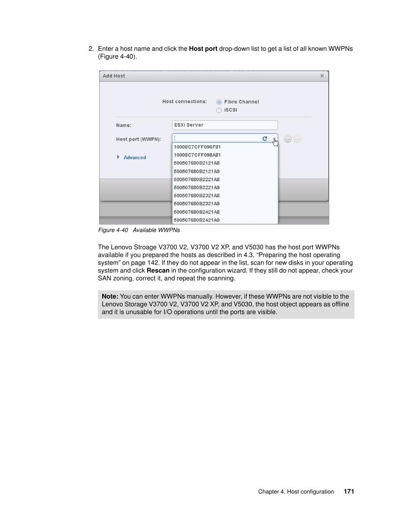
2. Enter a host name and click the Host port drop-down list to get a list of all known WWPNs (Figure 4-40).
Figure 4-40 Available WWPNs
The Lenovo Stroage V3700 V2, V3700 V2 XP, and V5030 has the host port WWPNs available if you prepared the hosts as described in 4.3, “Preparing the host operating system” on page 142. If they do not appear in the list, scan for new disks in your operating system and click Rescan in the configuration wizard. If they still do not appear, check your SAN zoning, correct it, and repeat the scanning.
Note: You can enter WWPNs manually. However, if these WWPNs are not visible to the Lenovo Storage V3700 V2, V3700 V2 XP, and V5030, the host object appears as offline and it is unusable for I/O operations until the ports are visible.
Chapter 4. Host configuration 171

3. Select the WWPN for your host (Figure 4-41).
Figure 4-41 Add a port to a list
4. If you want to add additional ports to your Host, click the plus sign (+).
5. Add all ports that belong to the host (Figure 4-42).
Figure 4-42 Add all WWPNs
172 Implementing the Lenovo Storage V3700 V2 and V5030 Systems

Figure 4-43 Manually added WWPN
6. If you are creating a Hewlett-Packard UNIX (HP-UX) or Target Port Group Support (TPGS) host, select Advanced, and more options appear (Figure 4-44). Select your host type.
Figure 4-44 Add Host: Advanced Settings
Creating offline hosts: If you want to create hosts that are offline or not connected currently, you can enter the WWPNs manually. Type them into the Host port (WWPN) field and add them to the list. See Figure 4-43.
Chapter 4. Host configuration 173

7. You can set the I/O Groups that your host can access. The host objects must belong to the same I/O groups as the volumes that you want to map. Otherwise, these volumes are not visible to the host. See Figure 4-45.
Figure 4-45 Setting I/O groups
8. Click Add Host, and the wizard creates the host (Figure 4-46).
Figure 4-46 Add Host task completes
Note: The Lenovo Storage V3700 V2, V3700 V2 XP, and V5030 supports a maximum of two nodes for each system. The two nodes are arranged as two I/O groups per cluster. Due to the host object limit per I/O group, for maximum host connectivity, it is best to create hosts that use single I/O groups.
174 Implementing the Lenovo Storage V3700 V2 and V5030 Systems

9. Click Close to return to the Hosts window. Repeat these steps for all of your Fibre Channel hosts. Figure 4-47 shows the Hosts window for all hosts after you create a second host.
Figure 4-47 All hosts: After you create a second host
After you add all of the Fibre Channel hosts, create volumes and map them to the created hosts. See Chapter 5, “Volume configuration” on page 189.
4.4.2 Configuring the Storage Systems for FC connectivity
You can configure the FC ports on the Lenovo Storage V3700 V2, V3700 V2 XP, and V5030 for use for certain connections only. This capability is referred to as port masking. In a system with multiple I/O groups and remote partnerships, port masking is a useful tool for ensuring peak performance and availability.
The following options are available per port:
� Any: Allow local and remote communication between nodes.� Local: Allow only local node communication.� Remote: Allow only remote node communication.� None: Do not allow any node communication.
In all cases, host I/O is still permitted, so the None option can be used to exclusively reserve a port for host I/O.
A limit of 16 logins exists per node from another node before an error is logged. A combination of port masking and SAN zoning can help you manage logins and provide optimum I/O performance with local, remote, and host traffic.
Chapter 4. Host configuration 175

To configure FC ports, complete the following steps:
1. Go to Settings → Network, as shown in Figure 4-48.
Figure 4-48 Opening the network settings view
2. Select Fibre Channel Ports and the Fibre Channel Ports configuration view displays, as shown in Figure 4-49.
Figure 4-49 The Fibre Channel Ports view
176 Implementing the Lenovo Storage V3700 V2 and V5030 Systems

3. To configure a port, right-click the port and select Modify. The window that is shown in Figure 4-50 opens.
Figure 4-50 Modifying the connection for Port 1
In this example, we select None to restrict traffic on this port to host I/O only. Click Modify to confirm the selection.
4. You can view connections between nodes, storage systems, and hosts by selecting Fibre Channel Connectivity while you are in the Network settings view. Choose the connections that you want to view and click Show Results, as shown in Figure 4-51.
Figure 4-51 Viewing FC connections between nodes, storage systems, and hosts
Note: This action configures Port 1 for all nodes. You cannot configure FC ports on a per node basis.
Chapter 4. Host configuration 177

4.4.3 Creating iSCSI hosts
To create iSCSI hosts, complete the following steps:
1. Click iSCSI and the iSCSI configuration wizard opens (Figure 4-52).
Figure 4-52 Add an iSCSI host
2. Enter a descriptive host name, type the iSCSI initiator name in the name field. Type the iSCSI port information in the iSCSI port field. If you want to add several initiator names to one host, repeat this step by clicking the plus sign (+).
3. If you are connecting an HP-UX or TPGS host, select Advanced (Figure 4-52) and select the correct host type (Figure 4-53). Click Add.
Figure 4-53 Create an iSCSI host: Advanced settings
178 Implementing the Lenovo Storage V3700 V2 and V5030 Systems

4. You can set the I/O groups that your host can access.
5. The wizard completes (Figure 4-54). Click Close.
Figure 4-54 Add an iSCSI host: Complete
6. Repeat these steps for every iSCSI host that you want to create. Figure 4-55 shows all of the hosts after you create two Fibre Channel hosts and one iSCSI host.
Figure 4-55 All hosts
Important: The host objects must belong to the same I/O groups as the volumes that you want to map. Otherwise, the host cannot see these volumes. For more information, see Chapter 5, “Volume configuration” on page 189.
The Lenovo Storage V3700 V2, V3700 V2 XP, and V5030 support a maximum of four nodes per system. These nodes are arranged as two I/O groups per cluster. Due to the host object limit per I/O group, for maximum host connectivity, it is best to create hosts that use single I/O groups.
Chapter 4. Host configuration 179
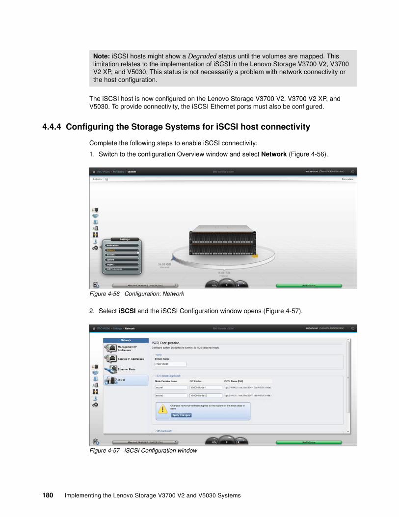
The iSCSI host is now configured on the Lenovo Storage V3700 V2, V3700 V2 XP, and V5030. To provide connectivity, the iSCSI Ethernet ports must also be configured.
4.4.4 Configuring the Storage Systems for iSCSI host connectivity
Complete the following steps to enable iSCSI connectivity:
1. Switch to the configuration Overview window and select Network (Figure 4-56).
Figure 4-56 Configuration: Network
2. Select iSCSI and the iSCSI Configuration window opens (Figure 4-57).
Figure 4-57 iSCSI Configuration window
Note: iSCSI hosts might show a Degraded status until the volumes are mapped. This limitation relates to the implementation of iSCSI in the Lenovo Storage V3700 V2, V3700 V2 XP, and V5030. This status is not necessarily a problem with network connectivity or the host configuration.
180 Implementing the Lenovo Storage V3700 V2 and V5030 Systems

3. The system waits until you apply the changes that you made. Click Apply Changes. All changes are applied, as shown in Figure 4-58.
Figure 4-58 Applying all iSCSI changes
4. The Configuration window (Figure 4-57 on page 180) shows an overview of all of the iSCSI settings for the Lenovo Storage V3700 V2, V3700 V2 XP, and V5030. You can configure the iSCSI alias, Internet Storage Name Service (iSNS) addresses, Challenge Handshake Authentication Protocol (CHAP), and the iSCSI IP address, which we also edit in the basic setup.
Chapter 4. Host configuration 181

5. Click Ethernet Ports to enter the iSCSI IP address (Figure 4-59). Repeat this step for each port that you want to use for iSCSI traffic.
Figure 4-59 Enter an iSCSI IP address
6. After you enter the IP address for each port, click Modify to enable the configuration.
7. After the changes are successfully applied, click Close (Figure 4-60).
Figure 4-60 iSCSI IP address that was successfully modified
Note: We advise that you reserve at least one port for the management IP address. Typically, reserve Port 1 for the management IP address and configure Port 2 for iSCSI. In our example, we use Port 1 due to limited cabling.
182 Implementing the Lenovo Storage V3700 V2 and V5030 Systems

8. Under Actions, you can check the hosts that are enabled for iSCSI. See Figure 4-61.
Figure 4-61 Actions menu to modify iSCSI hosts
9. By default, all iSCSI hosts are enabled (Figure 4-62).
Figure 4-62 Enabled iSCSI hosts
10.To modify virtual LAN (VLAN) settings, right-click the port again and click Modify VLAN. The window that is shown in Figure 4-63 opens. Check Enable to turn on VLAN tagging and set the tag in the field that is provided. The failover port needs to belong to the same VLAN so leave Apply change to the failover port too checked. Click Modify to confirm.
Figure 4-63 Modifying VLAN settings for Port 2 of Node 1
Chapter 4. Host configuration 183

11.Repeat the previous steps for all ports that need to be configured.
12.You can also configure iSCSI aliases, an iSNS name, and CHAP authentication. These options are located in the iSCSI Configuration view. To access this view, click iSCSI in the Network settings view, as shown in Figure 4-64.
Figure 4-64 Advanced iSCSI configuration
The Lenovo Storage V3700 V2, V3700 V2 XP, and V5030 is now configured and ready for iSCSI use. Document the initiator names of your storage canisters (Figure 4-57 on page 180) because you need them later. To create volumes and map them to a host, go to Chapter 5, “Volume configuration” on page 189.
184 Implementing the Lenovo Storage V3700 V2 and V5030 Systems

4.4.5 Creating SAS hostsTo create a SAS host, complete the following steps:
1. Click SAS Host, and the SAS host configuration wizard opens, as shown in Figure 4-65.
Figure 4-65 The SAS host configuration wizard
2. Enter a descriptive host name and click the SAS Ports drop-down list to view a list of all FC WWPNs that are visible to the system, as shown in Figure 4-66.
Figure 4-66 SAS WWPNs that are visible to the system
Chapter 4. Host configuration 185

3. If you previously prepared a SAS host, as described in 4.3, “Preparing the host operating system” on page 142, the WWPNs that you recorded in this section appear. If they do not appear in the list, verify that you completed all of the required steps and check your cabling. Then, click Rescan in the configuration wizard. Ensure that the ends of the SAS cables are aligned correctly.
4. Select the WWPNs for your host and click Add Port to List for each port. These WWPNs are added to the Port Definitions section, as shown in Figure 4-67.
Figure 4-67 Adding the host WWPNs
5. Click Advanced for the Advanced Settings section.
You can set the I/O groups that your host can access.
You can choose the host type. If you use HP/UX, OpenVMS, or TPGS, you must configure the host. Otherwise, the default option (Generic) is acceptable.
Note: You can enter WWPNs manually. However, if these WWPNs are not visible to the Lenovo Storage V3700 V2, V3700 V2 XP, and V5030 the host object appears as offline and it is unusable for I/O operations until the ports are visible.
Important: Host objects must belong to the same I/O groups as the volumes that you want to map. Otherwise, the volumes are not visible to the host.
The Lenovo Storage V3700 V2, V3700 V2 XP, and V5030 support a maximum of four nodes per system. These nodes are arranged as two I/O groups per cluster. Due to the host object limit per I/O group, for maximum host connectivity, it is best to create hosts that use single I/O groups.
186 Implementing the Lenovo Storage V3700 V2 and V5030 Systems

6. Click Add Host and the wizard completes, as shown in Figure 4-68.
Figure 4-68 Completion of the Add Host wizard
7. Click Close to return to the host view, which now lists your newly created host object, as shown in Figure 4-69.
Figure 4-69 The hosts view lists the newly created host object
8. Repeat these steps for all of your SAS hosts.
After all of the host objects are created, see Chapter 5, “Volume configuration” on page 189 to create volumes and map them to the hosts.
Chapter 4. Host configuration 187

188 Implementing the Lenovo Storage V3700 V2 and V5030 Systems

Chapter 5. Volume configuration
This chapter describes how to use the Lenovo Storage V3700 V2, V3700 V2 XP, and V5030 to create and map volumes. A volume is a logical disk on the Lenovo Storage V3700 V2, V3700 V2 XP, and V5030 that is provisioned out of a storage pool. Mappings are defined in the Lenovo Storage V3700 V2, V3700 V2 XP, V5030 between volumes and host objects. Then, the storage is ready to be used by the host operating systems.
For information about how to prepare host operating systems and create host objects in the Lenovo Storage V3700 V2, V3700 V2 XP, and V5030 see Chapter 4, “Host configuration” on page 139.
This chapter includes the following topics:
� 5.1, “Creating volumes” on page 190� 5.2, “Creating volumes by using the Quick Volume Creation option” on page 193� 5.3, “Mapping a volume to the host” on page 200� 5.4, “Creating custom volumes by using the Advanced option” on page 202� 5.5, “Using Real-time Compression Software” on page 205
5
© Copyright Lenovo 2018. All rights reserved. 189

5.1 Creating volumes
The graphical user interface (GUI) is the simplest means of volume creation. It presents different options in the Volumes menu, depending on the topology of the system.
To start the process of creating a volume or volumes, click the dynamic menu (function icons). Click Volumes (Figure 5-1).
Figure 5-1 Volumes menu
A list of existing volumes with their state, capacity, and associated storage pool is displayed.
To define a new basic volume, click Create Volumes (Figure 5-2).
Figure 5-2 Create Volumes window
The Create Volumes options tab opens the Create Volumes menu, which displays two potential creation methods, Quick Volume Creation and Advanced, and volume classes.
Note: The volume classes that are displayed on the Create Volumes menu depend on the topology of the system.
190 Implementing the Lenovo Storage V3700 V2 and V5030 Systems

Volumes can be created by using the Quick Volume Creation option or the Advanced option, as shown in Figure 5-3.
Figure 5-3 Quick and Advanced Volume Creation options
In Figure 5-3, the Quick Volume Creation option shows icons that enable the quick creation of basic and mirrored volumes (in standard topology). The Advanced option shows a custom icon that can be used to customize parameters of volumes. Custom volumes are described in more detail later in this chapter.
Independent of the topology of the system, the Create Volumes window displays a Basic volume icon in the Quick Volume Creation option and always shows a Custom volume icon in the Advanced option.
Clicking any of the three icons in the Create Volumes window opens a drop-down window where volume details can be entered.
Chapter 5. Volume configuration 191

Figure 5-4 uses a basic volume.
Figure 5-4 Quick Volume Creation option
Notes:
� A basic volume is a volume whose data is striped across all available managed disks (MDisks) in one storage pool.
� A mirrored volume is a volume with two physical copies, where each volume copy can belong to a different storage pool.
� A custom volume, in the context of this menu, is either a basic or mirrored volume with customization from default parameters.
You can use the Quick Volume Creation option to change the default provisioning of a basic or mirrored volume to thin-provisioned or compressed by using the capacity savings parameter.
192 Implementing the Lenovo Storage V3700 V2 and V5030 Systems

5.2 Creating volumes by using the Quick Volume Creation option
In this section, we use the Quick Volume Creation option to create basic and mirrored volumes in a system with standard topology. This section also describes how to create host-to-volume mapping.
5.2.1 Creating basic volumes by using the Quick Volume Creation option
The common volume is the basic volume. This type of volume is fully provisioned (allocated), and its entire size is dedicated to the defined volume. The host and the Lenovo Storage V3700 V2, V3700 V2 XP, and V5030 see the fully allocated space.
Create a basic volume by clicking the Basic icon (Figure 5-3 on page 191), which opens an additional input window where you can define the following information:
� Pool: The pool in which the volume is created (drop-down)
� Quantity: Number of volumes to create (numeric up/down)
� Capacity: Size of the volume
Units (drop-down)
� Capacity savings (drop-down):
– None – Thin-provisioned – Compressed
� Name: Name of the volume (cannot start with a numeric)
� I/O group
Chapter 5. Volume configuration 193

Figure 5-5 shows the creation of a basic volume.
Figure 5-5 Creating a basic volume
We suggest that you use a naming convention for volumes to help you easily identify the associated host or group of hosts. At a minimum, the naming convention needs to contain the name of the pool or a tag that identifies the underlying storage subsystem. It can also contain the host name that the volume is mapped to, or perhaps the content of this volume, for example, the name of applications to be installed.
After all of the characteristics of the basic volume are defined, it can be created by selecting one of these options:
� Create� Create and Map to Host
194 Implementing the Lenovo Storage V3700 V2 and V5030 Systems

In this example, we choose Create. (The volume can be mapped to the host later.) After you select an option, you see the following confirmation window (Figure 5-6).
Figure 5-6 Successful volume creation task
Success is also indicated by the state of the basic volume that is reported as Online (formatting) in the Create Volumes window (Figure 5-7).
Figure 5-7 Basic volume fast-format was introduced in V7.5 release
Note: The plus sign (+) icon that is highlighted in green in Figure 5-5 on page 194 can be used to create additional volumes in the same instance of the volume creation wizard.
Notes:
� The V7.5 release changed the default behavior of volume creation to introduce a new feature, which fills a fully allocated volume with zeros as a background task activity. Basic volumes are automatically formatted through the quick initialization process. With this process, fully allocated volumes are available for use immediately.
� Quick initialization requires a small amount of I/O to complete and limits the number of volumes that can be initialized at the same time. Volume actions, such as moving, expanding, shrinking, or adding a volume copy, are disabled when the specified volume is initializing. Those actions are available after the initialization process completes.
� The quick initialization process can be disabled in circumstances where it is not necessary. For example, if the volume is the target of a copy services function, the copy services operation formats the volume. The quick initialization process can also be disabled for performance testing so that the measurements of the raw system capabilities can occur without the need to wait for the process to complete.
Chapter 5. Volume configuration 195

5.2.2 Creating mirrored volumes by using Quick Volume Creation option
The Lenovo Storage V3700 V2, V3700 V2 XP, and V5030 offer the capability to mirror volumes, which means that a single volume that is presented to a host represents two physical copies. Each volume copy can belong to a different pool, and each copy has the same virtual capacity as the volume. When a server writes to a mirrored volume, the system writes the data to both copies and when it reads a mirrored volume, the system selects one of the copies to read. The system typically selects the primary copy, as indicated in the management GUI by an asterisk (*).
If one of the mirrored volume copies is temporarily unavailable, for example, because the storage system that provides the pool is unavailable, the volume remains accessible to servers. The system remembers the areas of the volume that are written and resynchronizes these areas when both copies are available.
The use of mirrored volumes offers these benefits:
� Improve the availability of volumes by protecting them from a single storage system failure.
� Provide an alternative method of data migration with better availability characteristics. � Convert between fully allocated volumes and thin-provisioned volumes.� Provide concurrent maintenance of a storage system that does not support concurrent
maintenance.
Note: Volume mirroring is not a true disaster recovery solution because both copies are accessed by the same node pair and addressable by only a single cluster, but it can improve availability.
196 Implementing the Lenovo Storage V3700 V2 and V5030 Systems
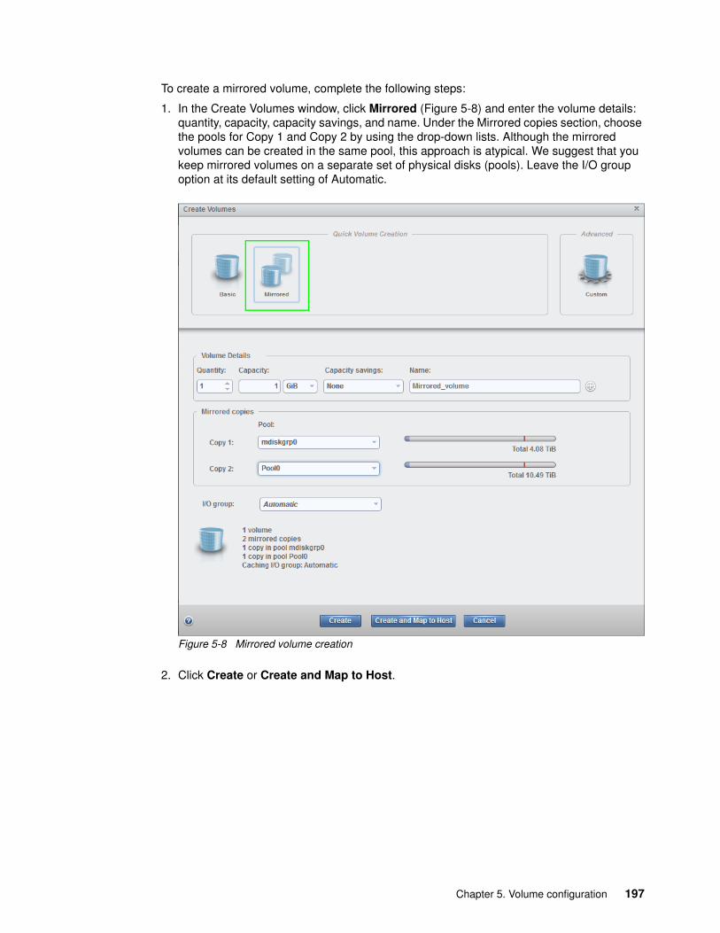
To create a mirrored volume, complete the following steps:
1. In the Create Volumes window, click Mirrored (Figure 5-8) and enter the volume details: quantity, capacity, capacity savings, and name. Under the Mirrored copies section, choose the pools for Copy 1 and Copy 2 by using the drop-down lists. Although the mirrored volumes can be created in the same pool, this approach is atypical. We suggest that you keep mirrored volumes on a separate set of physical disks (pools). Leave the I/O group option at its default setting of Automatic.
Figure 5-8 Mirrored volume creation
2. Click Create or Create and Map to Host.
Chapter 5. Volume configuration 197

3. The GUI displays the underlying command-line interface (CLI) command descriptions that executed to create the mirrored volume. The task is complete (Figure 5-9).
Figure 5-9 Mirrored volume created
Note: When you create a mirrored volume by using this option, you are not required to specify the mirrored synchronization rate. It defaults to 16 MiB. You can customize this synchronization rate by using the Advanced → Custom option.
198 Implementing the Lenovo Storage V3700 V2 and V5030 Systems

Quick Volume Creation option with capacity savingsWith the Quick Volume Creation option, you can alter the provisioning of a basic or mirrored volume into thin-provisioned or compressed by using the capacity savings parameter. Select either Thin-provisioned or Compressed from the drop-down list (Figure 5-10).
Figure 5-10 Quick Volume Creation option with the capacity savings parameter set to compressed
Alternatively, you can select Thin-provisioned from the drop-down list to define a thin-provisioned volume.
Chapter 5. Volume configuration 199

5.3 Mapping a volume to the host
After you create a volume, you can map a volume to a host. Follow these steps:
1. From the Create Volumes window, highlight the volume that you want to create a mapping for. Select Actions from the menu bar.
2. From the Actions menu, select Map to Host (Figure 5-11).
Figure 5-11 Map to Host option
3. The Map Volume to Host window opens. Click the down arrow to open the Select the Host drop-down list to select a host to map the volume to (Figure 5-12).
Figure 5-12 Mapping a volume to a host
Tip: An alternative way of opening the Actions menu is to highlight or select a volume. Then, click the right mouse button.
200 Implementing the Lenovo Storage V3700 V2 and V5030 Systems

4. Select a host from the list. Click Map (Figure 5-13).
Figure 5-13 Selected host
5. The Modify Mappings window displays the command details and a “Task completed” message (Figure 5-14). Click Close.
Figure 5-14 Successful completion of host-to-volume mapping
Chapter 5. Volume configuration 201

5.4 Creating custom volumes by using the Advanced option
Use the Advanced option of the Create Volumes window for custom volume creation. It provides an alternative method of defining the capacity savings options, such as thin-provisioning or compression, but it also expands the base-level default values for the available basic and mirrored volumes. You can tailor a custom volume for the mirror synchronization rate, cache mode, and fast-format.
The Advanced menu consists of several sections:
� Volume Details (mandatory and defines the capacity savings parameter) � Volume Location (mandatory and defines the pool or pools to use)� Thin Provisioning � Compressed � General (for changing the default values for cache mode and formatting) � Summary
Work through these sections to customize your custom volume as you want and commit these changes by clicking Create. See Figure 5-15.
Figure 5-15 Customization sections
5.4.1 Creating a custom thin-provisioned volume
A thin-provisioned volume can be defined and created by using the Advanced menu. In relation to application reads and writes, thin-provisioned volumes behave as though they are fully allocated.
Completion of additional subsection(s) required if selected
202 Implementing the Lenovo Storage V3700 V2 and V5030 Systems

When you create a thin-provisioned volume, you can specify two capacities:
� The real physical capacity that is allocated to the volume from the storage pool. The real capacity determines the quantity of extents that are initially allocated to the volume.
� The virtual capacity of the volume that is available to the host. The virtual capacity is the capacity of the volume that is reported to all other components, for example, FlashCopy, cache, and remote copy, and to the hosts.
To create a thin-provisioned volume, complete the following steps:
1. From the Create Volumes window, select the Advanced option to open the Volume Details section. You can enter the quantity, capacity (virtual), capacity savings (by choosing Thin-provisioned from the drop-down list), and name of the volume that is created (Figure 5-16).
Figure 5-16 Create a thin-provisioned volume
2. Click Volume Location to define the pool in which to create the volume by using the drop-down list in the Pool field to choose the pool. All other values, Volume copy type, Caching I/O group, Preferred node, and Accessible I/O groups can be left with their default values (Figure 5-17).
Figure 5-17 Volume Location
Chapter 5. Volume configuration 203

3. Click Thin Provisioning to manage the real and virtual capacity, expansion criteria, and grain size (Figure 5-18).
Figure 5-18 Thin Provisioning
The Thin Provisioning options are listed. The defaults are displayed in parentheses:
– Real capacity (2%). Specify the size of the real capacity space that is used during creation.
– Automatically expand (Enabled). This option enables the automatic expansion of real capacity, if additional capacity is allocated.
– Warning threshold (Enabled). Enter a threshold for receiving capacity alerts.
– Thin-Provisioned Grain Size (32 KiB). Specify the grain size for real capacity. This option describes the size of the chunk of storage to be added to used capacity. For example, when the host writes 1 MB of new data, the capacity is increased by adding four chunks of 256 KiB each.
Important: If you do not use the autoexpand feature, the volume goes offline after it reaches its real capacity.
The GUI also defaults to a grain size of 32 KiB. However, 256 KiB is the default when you use the CLI. The optimum choice of grain size depends on the volume use type:
� If you use the thin-provisioned volume as a FlashCopy source or target volume, use 256 KiB to maximize performance.
� If you use the thin-provisioned volume as a FlashCopy source or target volume, specify the same grain size for the volume and for the FlashCopy function.
For more information, see this website:
https://ibm.biz/BdrAa2
204 Implementing the Lenovo Storage V3700 V2 and V5030 Systems

4. Apply all required changes and click Create to define the volume (Figure 5-19).
Figure 5-19 Thin-provisioned volume created
5. You can directly start the wizard for mapping this volume to the host by clicking Create and Map to Host (Figure 5-18 on page 204).
5.5 Using Real-time Compression Software
The Real-time Compression function (RtC) requires a separately orderable license that is set on a per enclosure basis. One license is required for each control or expansion enclosure and each enclosure in any external storage systems that use virtualization. With the compression function, data is compressed as it is written to disk, saving extra capacity for the system. Only the Lenovo Storage V5030 models with an installed additional memory module (16 GB dual inline memory module (DIMM)) support compression. Ensure that you use the correct model and all necessary hardware before you purchase a compression license.
Chapter 5. Volume configuration 205

5.5.1 RtC overview
The Real-time Compression Software that is embedded in controller firmware addresses the requirements of primary storage data reduction, including performance. It uses a purpose-built technology that uses the Random Access Compression Engine (RACE). It offers the following benefits:
� Compression for active primary data
RtC can be used with active primary data. Therefore, it supports workloads that are not candidates for compression in other solutions. The solution supports the online compression of existing data. Storage administrators can regain free disk space in an existing storage system without requiring administrators and users to clean up or archive data. This configuration significantly enhances the value of existing storage assets, and the benefits to the business are immediate. The capital expense of upgrading or expanding the storage system is delayed.
� Compression for replicated or mirrored data
Remote volume copies can be compressed in addition to the volumes at the primary storage tier. This process reduces storage requirements in Metro Mirror and Global Mirror destination volumes, as well.
� No changes to the existing environment required
IBM RtC is part of the storage system. It was designed with the goal of transparency so that it can be implemented without changes to applications, hosts, networks, fabrics, or external storage systems. The solution is transparent to hosts, so users and applications continue to work as-is and compression occurs within the storage system.
� Overall savings in operational expenses
More data is stored in a rack space, so fewer storage expansion enclosures are required to store a data set. This reduced rack space has the following benefits:
– Reduced power and cooling requirements. More data is stored in a system, which requires less power and cooling per gigabyte or used capacity.
– Reduced software licensing for more functions in the system. More data that is stored per enclosure reduces the overall spending on licensing.
� Immediate disk space savings
The space reduction occurs when the host writes the data. This process is unlike other compression solutions in which the reduction is realized only after a post-process compression batch job is run.
5.5.2 Common use cases
This section addresses the most common use cases for implementing compression:
� General-purpose volumes� Databases� Virtualized infrastructures� Log server datastores
Tip: Implementing compression in controller firmware provides the same benefits to internal solid-state drives (SSDs) and externally virtualized storage systems.
206 Implementing the Lenovo Storage V3700 V2 and V5030 Systems

General-purpose volumesMost general-purpose volumes are used for highly compressible data types, such as home directories, CAD/CAM, oil and gas geoseismic data, and log data. Storing such types of data in compressed volumes provides immediate capacity reduction to the overall consumed space. More space can be provided to users without any change to the environment.
Many file types can be stored in general-purpose servers. However, for practical information, the estimated compression ratios are based on actual field experience. The expected compression ratios are 50% - 60%.
File systems that contain audio, video files, and compressed files are not good candidates for compression. The overall capacity savings on these file types are minimal.
DatabasesDatabase information is stored in table space files. High compression ratios are common in database volumes. Examples of databases that can greatly benefit from RtC are IBM DB2, Oracle, and Microsoft SQL Server. The expected compression ratios are 50% - 80%.
Virtualized infrastructuresThe proliferation of open systems virtualization in the market increased the use of storage space, with more virtual server images and backups that are kept online. The use of compression reduces the storage requirements at the source.
Examples of virtualization solutions that can greatly benefit from RtC are VMware, Microsoft Hyper-V, and kernel-based virtual machine (KVM). The expected compression ratios are 45% - 75%.
Log server datastoresLogs are a critical part for any IT department in any organization. Log aggregates or syslog servers are a central point for the administrators, and immediate access and a smooth work process is necessary. Log server datastores are good candidates for Real-time Compression. The expected compression ratios are up to 90%.
5.5.3 Real-time Compression concepts
The Random Access Compression Engine (RACE) technology is based on over 50 patents that are not primarily about compression. Instead, they define how to make industry standard Lempel-Ziv (LZ) compression of primary storage operate in real time and allow random access. The primary intellectual property behind this technology is the RACE component.
At a high level, the IBM RACE component compresses data that is written into the storage system dynamically. This compression occurs transparently, so Fibre Channel and iSCSI connected hosts are not aware of the compression. RACE is an inline compression technology, which means that each host write is compressed as it passes through controller firmware to the disks.
Important: Certain databases offer optional built-in compression. Generally, do not compress already compressed database files.
Tip: Virtual machines (VMs) with file systems that contain compressed files are not good compression candidates.
Chapter 5. Volume configuration 207

This technology has a clear benefit over other compression technologies that are based on post-processing. These technologies do not provide immediate capacity savings. Therefore, they are not a good fit for primary storage workloads, such as databases and active data set applications.
RACE is based on the Lempel-Ziv lossless data compression algorithm, and RACE operates in a real-time method. When a host sends a write request, the request is acknowledged by the write cache of the system, and then staged to the storage pool. As part of its staging, the write request passes through the compression engine and is then stored in compressed format on the storage pool. Therefore, writes are acknowledged immediately after they are received by the write cache. Compression occurs as part of the staging to internal or external physical storage.
Capacity is saved when the data is written by the host because the host writes are smaller when they are written to the storage pool.
RtC is a self-tuning solution that adapts to the workload that runs on the system at any moment.
5.5.4 Random Access Compression Engine
To understand why RACE is unique, you need to review traditional compression techniques. This description is not about the compression algorithm itself, that is, how the data structure is reduced in size mathematically. Rather, the description is about how the data is laid out within the resulting compressed output.
Compression utilitiesCompression is probably most known to users because of the widespread use of compression utilities, such as the zip and gzip utilities. At a high level, these utilities take a file as their input, and parse the data by using a sliding window technique. Repetitions of data are detected within the sliding window history, most often 32 KiB. Repetitions outside of the window cannot be referenced. Therefore, the file cannot be reduced in size unless data is repeated when the window “slides” to the next 32 KiB slot.
208 Implementing the Lenovo Storage V3700 V2 and V5030 Systems

Figure 5-20 shows compression that uses a sliding window, where the first two repetitions of the string “ABCD” fall within the same compression window and can be compressed by using the same dictionary. The third repetition of the string falls outside of this window and cannot be compressed by using the same compression dictionary as the first two repetitions, reducing the overall achieved compression ratio.
Figure 5-20 Compression that uses a sliding window
Traditional data compression in storage systemsThe traditional approach that is taken to implement data compression in storage systems is an extension of how compression works in the compression utilities that were previously mentioned. Similar to compression utilities, the incoming data is broken into fixed chunks, and then each chunk is compressed and extracted independently.
However, drawbacks exist to this approach. An update to a chunk requires a read of the chunk, followed by a recompression of the chunk to include the update. The larger the chunk size that is chosen, the heavier the I/O penalty to recompress the chunk. If a small chunk size is chosen, the compression ratio is reduced because the repetition detection potential is reduced.
Chapter 5. Volume configuration 209

Figure 5-21 shows an example of how the data is broken into fixed-size chunks (in the upper-left corner of the figure). It also shows how each chunk is compressed independently into variable-length compressed chunks (in the upper-right corner of the figure). The resulting compressed chunks are stored sequentially in the compressed output.
Although this approach evolved from compression utilities, it is limited to low-performance use cases because this approach does not provide real random access to the data.
Figure 5-21 Traditional data compression in storage systems
Random Access Compression EngineThe IBM patented Random Access Compression Engine implements an inverted approach when it is compared to traditional approaches to compression. RACE uses variable-size chunks for the input, and it produces fixed-size chunks for the output.
This method enables an efficient and consistent method to index the compressed data because the data is stored in fixed-size containers.
210 Implementing the Lenovo Storage V3700 V2 and V5030 Systems

Figure 5-22 shows Random Access Compression.
Figure 5-22 Random Access Compression
Location-based compressionBoth compression utilities and traditional storage system compression compress data by finding repetitions of bytes within the chunk that is being compressed. The compression ratio of this chunk depends on how many repetitions can be detected within the chunk. The number of repetitions is affected by how much the bytes that are stored in the chunk are related to each other. The relationship between bytes is driven by the format of the object.
For example, an office document might contain textual information, and an embedded drawing, such as this page. Because the chunking of the file is arbitrary, it has no notion of how the data is laid out within the document. Therefore, a compressed chunk can be a mixture of the textual information and part of the drawing.
This process yields a lower compression ratio because the mixed data types cause a suboptimal dictionary of repetitions. That is, fewer repetitions can be detected because a repetition of bytes in a text object is unlikely to exist in a drawing.
This traditional approach to data compression is also called location-based compression. The data repetition detection is based on the location of data within the same chunk.
This challenge was also addressed with the predecide mechanism that was introduced in version 7.1.
Predecide mechanismCertain data chunks have a higher compression ratio than others. Compressing part of the chunks saves little space but still requires resources, such as CPU and memory. To avoid spending resources on incompressible data and to use a different, more effective (in this case) compression algorithm, IBM invented a predecide mechanism that was first introduced in version 7.1.
Chapter 5. Volume configuration 211

The chunks that are under a certain compression ratio are skipped by the compression engine, saving CPU time and memory processing. Chunks that are decided not to be compressed with the main compression algorithm, but that still can be compressed well with another algorithm, are marked and processed. The result can vary because predecide does not check the entire block, only a sample of it.
Figure 5-23 shows how the detection mechanism works.
Figure 5-23 Detection mechanism
Temporal compressionRACE offers a technology leap, which is called temporal compression, beyond location-based compression.
When host writes arrive to RACE, they are compressed and fill fixed-size chunks that are called compressed blocks. Multiple compressed writes can be aggregated into a single compressed block. A dictionary of the detected repetitions is stored within the compressed block. When applications write new data or update existing data, the data is typically sent from the host to the storage system as a series of writes. Because these writes are likely to originate from the same application and be from the same data type, more repetitions are detected by the compression algorithm.
This type of data compression is called temporal compression because the data repetition detection is based on the time that the data was written into the same compressed block. Temporal compression adds the time dimension that is not available to other compression algorithms. Temporal compression offers a higher compression ratio because the compressed data in a block represents a more homogeneous set of input data.
212 Implementing the Lenovo Storage V3700 V2 and V5030 Systems

Figure 5-24 shows how three writes that are sent one after the other by a host are in different chunks. They are compressed in different chunks because their locations in the volume are not adjacent. This approach yields a lower compression ratio because the same data must be compressed non-natively by using three separate dictionaries.
Figure 5-24 Location-based compression
When the same three writes, as shown on Figure 5-25, are sent through RACE, the writes are compressed together by using a single dictionary. This approach yields a higher compression ratio than location-based compression.
Figure 5-25 Temporal compression
5.5.5 RACE technology in the Lenovo Storage V-series software stack
It is important to understand where the RACE technology is implemented in the Lenovo Storage V-series software stack. This location determines how it applies to the Lenovo Storage V3700 V2, V3700 V2 XP, and V5030 components.
RACE technology is implemented in the Lenovo Storage V-series thin provisioning layer, and it is an organic part of the stack. Compression is transparently integrated with existing system management design. All of the Lenovo Storage V-series advanced features are supported on compressed volumes. You can create, delete, migrate, map (assign), and unmap (unassign) a compressed volume as though it is a fully allocated volume.
In addition, you can use RtC with Easy Tier on the same volumes. This compression method provides nondisruptive conversion between compressed and decompressed volumes. This conversion provides a uniform user experience and eliminates the need for special procedures when you work with compressed volumes.
Chapter 5. Volume configuration 213

The software stack is shown in Figure 5-26.
Figure 5-26 RACE integration within the Lenovo Storage V-series software stack
5.5.6 Write request data flow
When a host sends a write request, it reaches the upper-cache layer. The host is immediately sent an acknowledgment of its I/Os.
When the upper-cache layer destages to the RACE, the I/Os are sent to the thin-provisioning layer. Then, they are sent to the RACE, and if necessary, to the original host write or writes. The metadata that holds the index of the compressed volume is updated, if needed, and compressed, as well.
5.5.7 Read request data flow
When a host sends a read request for compressed data, the request is forwarded directly to the RtC component:
� If the RtC component contains the requested data, the cache replies to the host with the requested data without needing to read the data from the lower-level cache or disk.
� If the RtC component does not contain the requested data, the request is forwarded to the lower-level cache.
214 Implementing the Lenovo Storage V3700 V2 and V5030 Systems

� If the lower-level cache contains the requested data, it is sent up the stack and returned to the host without accessing the storage.
� If the lower-level cache does not contain the requested data, it sends a read request to the storage for the requested data.
5.5.8 Compression of existing data
In addition to compressing data in real time, you can also compress existing data sets (convert volume to compressed). You must change the capacity savings settings of the volume by right-clicking a volume and selecting Modify Capacity Savings, as shown in Figure 5-27.
Figure 5-27 Modifying capacity savings
In the drop-down list, select Compression as the capacity savings method, as shown in Figure 5-28.
Figure 5-28 Selecting the capacity savings method
After the copies are fully synchronized, the original volume copy is deleted automatically.
As a result, compressed data is on the existing volume. This process is nondisruptive, so the data remains online and accessible by applications and users.
By using this capability, clients can regain space from the storage pool to use for other applications.
Chapter 5. Volume configuration 215

With the virtualization of external storage systems, the ability to compress already stored data enhances and accelerates the benefit to users, enhancing the return on investment.
5.5.9 Creating custom compressed volumes
The configuration of compressed volumes is similar to thin-provisioned volumes. To create a compressed volume, complete the following steps:
1. From the Create Volumes window, select Advanced to open the Volume Details section where you can enter the quantity, capacity (virtual), capacity savings (by choosing Compressed from the drop-down list), and name (Figure 5-29).
Figure 5-29 Defining a volume as compressed by using the capacity savings method
2. Open the Volume Location subsection and select the pool in which the compressed volume is created. (Use all other parameter defaults.)
Important: Lenovo Storage V5030 reserve resources, such as CPU cores and RAM memory, after you create one compressed volume or volume copy. This reserve might affect your system performance if you do not plan for the reserve in advance.
216 Implementing the Lenovo Storage V3700 V2 and V5030 Systems

3. Click Compression to confirm that Real Capacity is set to a minimum of the default value of 2%. (Use all other parameter defaults.) See Figure 5-30.
Figure 5-30 Selecting a compressed volume in the Advanced custom settings
4. Confirm and commit your selection by clicking Create.
5.5.10 Custom mirrored volumes
The Advanced option in the Create Volumes window is used to customize volume creation. Use this feature to override the default options and tailor volume creation to your specific environment.
Chapter 5. Volume configuration 217

Modifying mirrored sync rate The mirror sync rate can be changed from the default setting by clicking Advanced and selecting Volume Location on the Create Volumes window. This option sets the priority of the copy synchronization progress, allowing a preferential rate to be set for more important volumes (Figure 5-31).
Figure 5-31 Customization of the mirrored sync rate
218 Implementing the Lenovo Storage V3700 V2 and V5030 Systems

The progress of formatting and synchronizing a new mirrored volume can be checked from the Running Tasks status indicator. This list reports the progress of all currently running tasks, including the volume format and volume synchronization (Figure 5-32).
Figure 5-32 Progress of the running tasks
Creating a custom thin-provisioned mirrored volume Use the Advanced option in the Create Volumes window to customize volume creation. By using this feature, you can override the default options and tailor volume creation to the specifics of your environment.
The mirror sync rate can be changed from the default setting by clicking Advanced and selecting Volume Location on the Create Volumes window. This option sets the priority of the copy synchronization progress, allowing a preferential rate to be set for more important mirrored volumes.
Chapter 5. Volume configuration 219

The summary shows you the capacity information and the allocated space. You can click Advanced and customize the thin-provision settings or the mirror synchronization rate. After you create the volume, the confirmation window opens (Figure 5-33).
Figure 5-33 Confirmation window
The initial synchronization of thin-mirrored volumes is fast when a small amount of real and virtual capacity is used.
220 Implementing the Lenovo Storage V3700 V2 and V5030 Systems

Chapter 6. Storage migration
This chapter describes the steps of the storage migration wizard. The storage migration wizard migrates data from existing external storage systems to the internal capacity of the Lenovo Storage V3700 V2, V3700 V2 XP, and V5030. Migrating data from other storage systems to the Lenovo Storage V3700 V2, V3700 V2 XP, and V5030 storage systems consolidate storage and allows the benefits of the Lenovo Storage V3700 V2, V3700 V2 XP, and V5030 functionality, such as the easy-to-use GUI, internal virtualization, thin provisioning, and FlashCopy, to be realized across all volumes.
Storage migration uses the Volume Mirroring functionality to allow reads and writes during the migration, minimizing disruption and downtime. After the migration completes, you can retire the existing system. You can use storage migration to migrate data from other Storwize systems, such as the IBM Storwize V5000 for Lenovo or IBM Storwize V3700 for Lenovo.
This chapter includes the following topics:
� 6.1, “Interoperability and compatibility” on page 222� 6.2, “Storage migration wizard” on page 222
6
Command-line interface (CLI): For more information about the command-line interface setup, see Appendix A, “CLI setup and SAN Boot” on page 707.
Manually migrating data: For more information about migrating data manually, see Chapter 11, “External storage virtualization” on page 549.
© Copyright Lenovo 2018. All rights reserved. 221

6.1 Interoperability and compatibility
Interoperability is an important consideration when a new storage system is set up in an environment that contains existing storage infrastructure. In this section, we describe how to check that the storage environment, the existing storage system, and the Lenovo Storage V3700 V2, V3700 V2 XP, and V5030 are ready for the data migration process.
To ensure system interoperability and compatibility among all elements that connect to the storage area network (SAN) fabric, check the proposed configuration Lenovo Support Site. Lenovo Support Site can confirm whether the solution is supported and provide recommendations for hardware and software levels.
For more information about the interoperability, see this websites:
https://datacentersupport.lenovo.com/tw/en/products/storage/lenovo-storage/v3700v2/6535/documentation
https://datacentersupport.lenovo.com/tw/en/products/storage/lenovo-storage/v5030/6536/documentation
6.2 Storage migration wizard
The Lenovo Storage V3700 V2, V3700 V2 XP, and V5030 storage migration wizard simplify the migration task. The wizard features easy-to-follow panels that guide users through the entire process.
6.2.1 External virtualization capability
All of the Lenovo Storage V3700 V2, V3700 V2 XP, and V5030 models can migrate storage from external controllers, including migrating from any other previous generation Storwize system. The Lenovo Storage V3700 V2, V3700 V2 XP, and V5030 use the functionality that is provided by the external virtualization capability of the Lenovo Storage V3700 V2, V3700 V2 XP, and V5030 to perform the migration. This capability places external Fibre Channel (FC)-connected logical units (LUs) under the control of the Lenovo Storage V3700 V2, V3700 V2 XP, and V5030. After the volumes are virtualized, hosts continue to access them through the Lenovo Storage V3700 V2, V3700 V2 XP, and V5030, which acts as a proxy.
The difference between the Lenovo Storage V3700 V2, V3700 V2 XP, and V5030 models is that the Lenovo Storage V3700 V2 and Lenovo Storage V3700 V2 XP models can perform data migration only. After the data is migrated, the external controller’s storage cannot be virtualized. The Lenovo Storage V5030 can be used to migrate data from external storage controllers and externally virtualize the storage of the external controller. For more information about external virtualization, see Chapter 11, “External storage virtualization” on page 549.
6.2.2 Model and adapter card considerations
Storage migration can use either the Fibre Channel SAN or direct-attach serial-attached Small Computer System Interface (SCSI) (SAS) connections to perform the data transfer.
222 Implementing the Lenovo Storage V3700 V2 and V5030 Systems

Fibre Channel migration to a Lenovo Storage V3700 V2, V3700 V2 XP, and V5030 require the purchase of a pair of the optional 16 Gb FC adapter cards.
SAS migration on the Lenovo Storage V3700 V2 and Lenovo Storage V5030 systems require the purchase of a pair of optional SAS adapter cards. SAS migration on Lenovo Storage V3700 V2 XP can be performed without an adapter card by using the onboard SAS host attachment ports.
Table 6-1 summarizes the requirements for each model.
Table 6-1 Comparison of Lenovo Storage V3700 V2, V3700 V2 XP, and V5030 models for storage migration
6.2.3 Overview of the storage migration wizard
An overview of the storage migration wizard process includes the following considerations:
1. Typically, storage systems divide storage into many Small Computer System Interface (SCSI) LUs that are presented on a Fibre Channel SAN to hosts. Storage can also be presented through direct SAS attachment to a host. In general, the steps to migrate either one of these storage systems are the same.
2. Input/output (I/O) to the LUNs must be stopped and changes must be made to the mapping of the storage system LUs and to the SAN fabric zoning or SAS connectivity so that the original LUs are presented directly to the Lenovo Storage V3700 V2, V3700 V2 XP, and V5030 and not to the hosts. The Lenovo Storage V3700 V2, V3700 V2 XP, and V5030 discover the external LUs as unmanaged (not a member of any storage pools) managed disks (MDisks).
3. The unmanaged MDisks are then imported to the Lenovo Storage V3700 V2, V3700 V2 XP, and V5030 as image mode MDisks and placed in a storage pool. This storage pool is now a logical container for the externally attached LUs.
4. Each volume has a one-to-one mapping with an image mode MDisk. From a data perspective, the image mode volume represents the SAN-attached LUs exactly as they were before the import operation. The image mode volumes are on the same physical drives of the existing storage system and the data remains unchanged. The Lenovo Storage V3700 V2, V3700 V2 XP, and V5030 are presenting active images of the SAN-attached LUs and is acting as a proxy.
5. You need to remove the existing storage system multipath device driver from the hosts. Then, configure the hosts for the Lenovo Storage V3700 V2, V3700 V2 XP, and V5030 attachment. If you are migrating over Fibre Channel, further zoning changes are made for host-to-Lenovo Storage V3700 V2, V3700 V2 XP, V5030 SAN connections. The Lenovo Storage V3700 V2, V3700 V2 XP, and V5030 hosts are defined with worldwide port names (WWPNs) and the volumes are mapped to the hosts. After the volumes are mapped, the hosts discover the Lenovo Storage V3700 V2, V3700 V2 XP, and V5030 volume through a host rescan or reboot operation.
6. The Lenovo Storage V3700 V2, V3700 V2 XP, and V5030 volume mirror operations are then initiated. The image mode volumes are mirrored to generic volumes. The mirrors are
Lenovo V3700 V2 Lenovo V3700 V2 XP Lenovo V5030
External virtualization Not supported Not supported Licensed feature
FC SAN migration With 16 G FC cards With 16 G FC cards With 16 G FC cards
SAS device adapter (DA) migration
With 12 G SAS cards Yes (onboard ports) With 12 G SAS cards
Chapter 6. Storage migration 223

online migration tasks, which means that a defined host can still access and use the volumes during the mirror synchronization process.
7. After the mirror operations are complete, the volume mirror relationships and the image mode volumes are removed. The other storage system LUs are migrated and the now redundant existing storage can be retired or reused elsewhere.
6.2.4 Storage migration wizard tasks
The storage migration wizard is designed for the easy and nondisruptive migration of data from other storage systems to the internal capacity of the Lenovo Storage V3700 V2, V3700 V2 XP, and V5030.
This section describes the following storage migration wizard tasks:
� Avoiding data loss� Verifying prerequisites for Fibre Channel connections� Verifying prerequisites for SAS connections� Accessing the storage migration wizard� Identifying restrictions and prerequisites for the wizard� Preparing the environment for migration� Mapping storage� Migrating MDisks� Configuring hosts� Mapping volumes to hosts� Selecting a storage pool� Finishing the storage migration wizard� Finalizing migrated volumes
Avoiding data lossIt is prudent to avoid any potential data loss by creating a backup of all of the data that is stored on the hosts, the existing storage systems, and the Lenovo Storage V3700 V2, V3700 V2 XP, and V5030 before you use the storage migration wizard.
Important: If you are migrating volumes from another IBM Storwize for Lenovo product, be aware that the target Lenovo Storage V3700 V2, V3700 V2 XP, and V5030 systems need to be configured at the replication layer for the source to discover the target system as a host. The default layer setting for the Lenovo Storage V3700 V2, V3700 V2 XP, and V5030 are storage.
Ensure that the Lenovo Storage V3700 V2, V3700 V2 XP, and V5030 systems are configured as a replication layer system. Enter the following command:
chsystem -layer replication
If you do not enter this command, you cannot add the target system as a host on the source storage system or see source volumes on the target system.
To change the source Storwize system to the storage layer, enter the following command:
chsystem -layer storage
For more information about layers and how to change them, see Chapter 10, “Copy services” on page 393.
224 Implementing the Lenovo Storage V3700 V2 and V5030 Systems

Verifying prerequisites for Fibre Channel connectionsCable this system into the SAN of the external storage that you want to migrate. Ensure that your system is cabled and zoned into the same storage area network (SAN) as the external storage system that you are migrating. If you are using Fibre Channel, connect the Fibre Channel cables to the Fibre Channel ports in both canisters of your system, and then to the Fibre Channel network. If you are using Fibre Channel over Ethernet (FCoE), connect Ethernet cables to the 10 Gbps Ethernet ports.
Verifying prerequisites for SAS connectionsFor migrating from a IBM Storwize V3500, Storwize V3700, or Storwize V5000 for Lenovo system, ensure that all systems are running a software level that can support SAS migration (minimum version 7.6.1.0).
Cable the Lenovo Storage V3700 V2, V3700 V2 XP, and V5030 directly to the external storage system that you want to migrate. Depending on the Lenovo Storage V3700 V2, V3700 V2 XP, and V5030 models, the cabling differs slightly. The Lenovo Storage V3700 V2 and Lenovo Storage V5030 need four SAS cables (two SAS cables per node canister) that are connected to the optional SAS card. The Lenovo Storage V3700 V2 XP needs four SAS cables (two SAS cables per node canister) that are connected to SAS port 2 and SAS port 3.
The IBM Storwize V3500 for Lenovo or IBM Storwize V3700 for Lenovo source systems require two cables per node canister. Each canister must be connected to eachLenovo Storage V3700 V2, V3700 V2 XP, and V5030 canister. On the V3500 or V3700, you can use SAS ports 1, 2, or 3. Do not use SAS port 4. Examples of how to connect a Lenovo Storage V3700 V2, V3700 V2 XP, and V5030 to the IBM Storwize V3500/V3700 for Lenovo are shown in Figure 6-1, Figure 6-2 on page 226, and Figure 6-3 on page 226.
Figure 6-1 Connecting SAS cables from a Storwize V3500 or V3700 for Leovo to a Lenovo Storage V3700 V2 system
Chapter 6. Storage migration 225

Figure 6-2 Connecting SAS cables from a Storwize V3500 or V3700 for Lenovo to a Lenovo Storage V3700 V2 XP system
Figure 6-3 Connecting SAS cables from a Storwize V3500 or V3700 for Lenovo to a Lenovo Storage V5030 system
The IBM Storwize V5000 for Lenovo source systems require two cables per node canister. Each canister must be connected to each Lenovo Storage V3700 V2, V3700 V2 XP, and V5030 canister. On the IBM Storwize V5000 for Lenovo , you must use SAS port 1 or 2. Do not use SAS port 3 or 4.
226 Implementing the Lenovo Storage V3700 V2 and V5030 Systems

Examples of how to connect a Lenovo Storage V3700 V2, V3700 V2 XP, and V5030 to an IBM Storwize V5000 for Lenovo are shown in Figure 6-4, Figure 6-5, and Figure 6-6 on page 228.
Figure 6-4 Connecting SAS cables from an IBM Storwize V5000 for Lenovo system to a Lenovo Storage V3700 V2 system
Figure 6-5 Connecting SAS cables from an IBM Storwize V5000 for Lenovo system to a Lenovo Storage V3700 V2 XP system
Chapter 6. Storage migration 227

Figure 6-6 Connecting SAS cables from an IBM Storwize V5000 for Lenovo system to a Lenovo Storage V5030 system
228 Implementing the Lenovo Storage V3700 V2 and V5030 Systems

Accessing the storage migration wizardSelect System Migration in the Pools menu (Figure 6-7) to open the System Migration panel. The System Migration panel provides access to the storage migration wizard and displays the migration progress information.
Figure 6-7 Pools menu
Chapter 6. Storage migration 229

Click Start New Migration to begin the storage migration wizard. Figure 6-8 shows the System Migration panel.
Figure 6-8 System Migration panel
230 Implementing the Lenovo Storage V3700 V2 and V5030 Systems
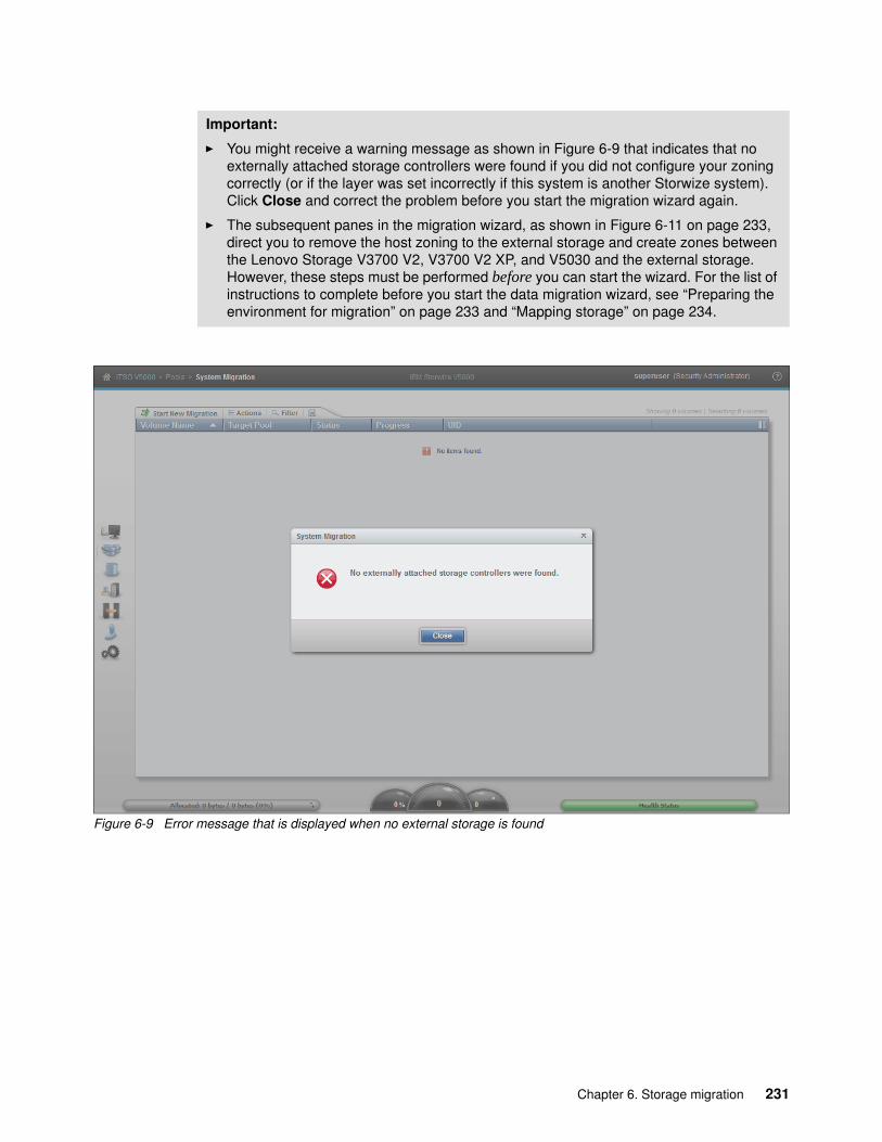
Figure 6-9 Error message that is displayed when no external storage is found
Important:
� You might receive a warning message as shown in Figure 6-9 that indicates that no externally attached storage controllers were found if you did not configure your zoning correctly (or if the layer was set incorrectly if this system is another Storwize system). Click Close and correct the problem before you start the migration wizard again.
� The subsequent panes in the migration wizard, as shown in Figure 6-11 on page 233, direct you to remove the host zoning to the external storage and create zones between the Lenovo Storage V3700 V2, V3700 V2 XP, and V5030 and the external storage. However, these steps must be performed before you can start the wizard. For the list of instructions to complete before you start the data migration wizard, see “Preparing the environment for migration” on page 233 and “Mapping storage” on page 234.
Chapter 6. Storage migration 231

Identifying restrictions and prerequisites for the wizardThis panel of the storage migration wizard describes the restrictions and prerequisites for the wizard, as shown in Figure 6-10.
Figure 6-10 Before you begin the storage migration wizard
RestrictionsConfirm that the following conditions are met:
� You are not using the storage migration wizard to migrate cluster hosts, including clusters of VMware hosts and Virtual I/O Servers (VIOS).
� You are not using the storage migration wizard to migrate SAN Boot images.
If the restrictions options cannot be selected, the migration must be performed outside of this wizard because more steps are required. For more information, see the Lenovo Storage V3700 V2, V3700 V2 XP, and V5030 in Lenovo Information Center at this website:
http://systemx.lenovofiles.com/mobile/help/topic/com.lenovo.storage.v3700.doc/lenovo_vseries.html
The VMware vSphere Storage vMotion feature might be an alternative for migrating VMware clusters. For more information, see this website:
http://www.vmware.com/products/vsphere/features/storage-vmotion.html
For more information about migrating SAN Boot images, see Appendix A, “CLI setup and SAN Boot” on page 707.
232 Implementing the Lenovo Storage V3700 V2 and V5030 Systems

PrerequisitesConfirm that the following prerequisites apply:
� Ensure that the Lenovo Storage V3700 V2, V3700 V2 XP, and V5030, existing storage system, hosts, and Fibre Channel ports are physically connected to the SAN fabrics.
� If VMware ESX hosts are involved in the data migration, ensure that the VMware ESX hosts are set to allow volume copies to be recognized. For more information, see the VMware ESX product documentation at this website:
http://www.vmware.com/support/pubs/vsphere-esxi-vcenter-server-pubs.html?
If all options can be selected, click Next. In all other cases, you cannot select Next and the data must be migrated without the use of this wizard.
Preparing the environment for migrationFigure 6-11 shows the Prepare Environment for Migration panel. Follow the instructions that are provided in this pane carefully. When all of the required tasks are complete, click Next.
Figure 6-11 Prepare the migration environment
Chapter 6. Storage migration 233

Mapping storageFollow the instructions that are shown in the Map Storage pane that is shown in Figure 6-12. Record all of the details carefully because the information is used in later panels. Table 6-2 shows an example table for you to use to capture the information that relates to the external storage system LUs.
Figure 6-12 Directions to record migration data
Table 6-2 Example table to capture the external LU information
LU name Controller Array SCSI ID Host name Capacity
V3700external0 Node2 V3700 0 50 GiB
V3700external1 Node1 V3700 1 50 GiB
V3700external2 Node2 V3700 2 50 GiB
V3700external3 Node1 V3700 3 50 GiB
V3700external4 Node2 V3700 4 50 GiB
V3700external5 Node1 V3700 5 50 GiB
SCSI ID: Record the SCSI ID of the LUs to which the host is originally mapped. Certain operating systems do not support the change of the SCSI ID during the migration.
234 Implementing the Lenovo Storage V3700 V2 and V5030 Systems
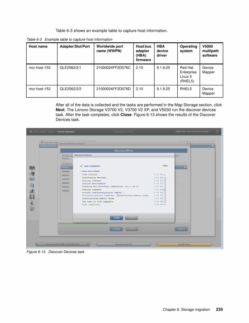
Table 6-3 shows an example table to capture host information.
Table 6-3 Example table to capture host information
After all of the data is collected and the tasks are performed in the Map Storage section, click Next. The Lenovo Storage V3700 V2, V3700 V2 XP, and V5030 run the discover devices task. After the task completes, click Close. Figure 6-13 shows the results of the Discover Devices task.
Figure 6-13 Discover Devices task
Host name Adapter/Slot/Port Worldwide port name (WWPN)
Host bus adapter (HBA)firmware
HBA device driver
Operating system
V5000 multipath software
mcr-host-153 QLE2562/2/1 21000024FF2D076C 2.10 9.1.9.25 Red Hat Enterprise Linux 5 (RHEL5)
Device Mapper
mcr-host-153 QLE2562/2/2 21000024FF2D076D 2.10 9.1.9.25 RHEL5 DeviceMapper
Chapter 6. Storage migration 235

Migrating MDisksSelect the MDisks to migrate and click Next. Figure 6-14 shows the Migrating MDisks panel.
Figure 6-14 Migrating MDisks panel
MDisk selection: Select only the MDisks that are applicable to the current migration plan. After the current migration completes, you can start another migration to migrate any remaining MDisks.
236 Implementing the Lenovo Storage V3700 V2 and V5030 Systems

The Lenovo Storage V3700 V2, V3700 V2 XP, and V5030 run the Import MDisks task. After the task completes, click Close. Figure 6-15 shows the result of the Import MDisks task. The volumes show in the background after the task completes.
Figure 6-15 Import MDisks task
Chapter 6. Storage migration 237

Configuring hosts
Follow this step of the wizard to select or configure new hosts as required. Figure 6-16 shows the Configure Hosts (optional) panel.
Figure 6-16 Configure Hosts panel
Note: This step is optional. You can bypass it by selecting Next and moving to “Mapping volumes to hosts” on page 242.
238 Implementing the Lenovo Storage V3700 V2 and V5030 Systems

If hosts are defined, they are listed in the panel as shown in Figure 6-20 on page 241. In our case, no hosts are defined, so they can be created by selecting the Add Host option. This option opens a window, as shown in Figure 6-17.
Figure 6-17 Add Host window
Select your connection type. Name the host, and assign the ports (in our case, Fibre Channel WWPNs). In the advanced settings, assign the I/O group ownership and host type as shown in Figure 6-18. For more information about I/O group assignment, see Chapter 4, “Host configuration” on page 139.
Figure 6-18 The details to add a host are complete
Chapter 6. Storage migration 239

Click Add to complete the task, as shown in Figure 6-19.
Figure 6-19 The task to create a host is complete
240 Implementing the Lenovo Storage V3700 V2 and V5030 Systems

The host is listed in the original Configure Hosts (optional) panel, as shown in Figure 6-20.
Figure 6-20 Configure Hosts panel that lists the host
Chapter 6. Storage migration 241

Mapping volumes to hostsUse this step of the wizard to select the migrated volumes to map them to hosts. Figure 6-21 shows the Map Volumes to Hosts (optional) panel.
Figure 6-21 Map Volumes to Hosts panel
The image mode volumes are listed, the nand ames of which are assigned automatically by the Lenovo Storage V3700 V2, V3700 V2 XP, V5030 storage systems. The names can be changed to reflect more meaningful names to the user by selecting the volume and clicking Rename in the Actions menu.
Names: The names of the image mode volumes must begin with a letter. The name can be a maximum of 63 characters. You can use the following valid characters:
� Uppercase letters (A - Z)� Lowercase letters (a - z)� Digits (0 - 9)� Underscore (_)� Period (.)� Hyphen (-)� Blank space
The names must not begin or end with a space.
242 Implementing the Lenovo Storage V3700 V2 and V5030 Systems

Hold Ctrl and click to select multiple volumes. Click Map to Host to select the host as shown in Figure 6-22, and click Map.
Figure 6-22 Modify host mappings
Chapter 6. Storage migration 243

The host mappings are added as shown in Figure 6-23. Click Close to return to the Map Volumes to Hosts panel.
Figure 6-23 Adding host mappings task
Figure 6-24 shows that the host mappings are in place for the imported volumes. Click Next.
Figure 6-24 Map Volumes to Hosts panel with completed host mappings
244 Implementing the Lenovo Storage V3700 V2 and V5030 Systems

Selecting a storage poolTo continue with the storage migration wizard, you must select a storage pool to migrate the imported volumes to, as shown in Figure 6-25. The destination storage pool is an internal storage pool of the Lenovo Storage V3700 V2, V3700 V2 XP, and V5030. Ensure that enough space exists in the selected storage pool to accommodate the migrated volume. The migration task runs in the background and results in a copy of the data that is placed on the MDisks in the selected storage pool.
The process uses the volume mirroring function that is included with the Lenovo Storage V3700 V2, V3700 V2 XP, and V5030.
Figure 6-25 Storage pool selection
Chapter 6. Storage migration 245

Select a pool and click Next. The task begins and completes as shown in Figure 6-26.
Figure 6-26 Pool selection task complete
Click Close to move to the end of the migration wizard.
246 Implementing the Lenovo Storage V3700 V2 and V5030 Systems

Finishing the storage migration wizardClick Finish to end the storage migration wizard as shown in Figure 6-27.
Figure 6-27 Migration wizard complete
Chapter 6. Storage migration 247

The end of the storage migration wizard is not the end of the data migration task. It is still in progress. A percentage indicator is displayed in the Storage Migration panel as shown in Figure 6-28.
Figure 6-28 Storage migration progress
248 Implementing the Lenovo Storage V3700 V2 and V5030 Systems

Finalizing migrated volumesWhen the migration completes with all of the progress indicators at 100%, select all of the volume migrations that you want to finalize by holding down Ctrl and clicking the volumes. Then, select Actions → Finalize as shown in Figure 6-29. Alternatively, right-click the selected volumes and click Finalize.
Figure 6-29 Finalize storage migration
Chapter 6. Storage migration 249

You are asked to confirm the number of volumes that you want to finalize as shown in Figure 6-30.
Figure 6-30 Confirm volumes to finalize
250 Implementing the Lenovo Storage V3700 V2 and V5030 Systems

Verify that the volume names and the number of migrations are correct and click OK. The image mode volumes are deleted and the associated image mode MDisks from the migration storage pool are removed. Figure 6-31 shows the completed tasks.
Figure 6-31 Removal of image mode volumes
When the finalization completes, the data migration to the Lenovo Storage V3700 V2, V3700 V2 XP, and V5030 are finished. Remove the zoning and retire the external storage system.
Chapter 6. Storage migration 251

252 Implementing the Lenovo Storage V3700 V2 and V5030 Systems

Chapter 7. Storage pools
This chapter describes how Lenovo Storage V3700 V2, V3700 V2 XP, and V5030 manage physical storage resources. All storage resources that are under Lenovo Storage V3700 V2, V3700 V2 XP, and V5030 control are managed by using storage pools. Storage pools make it easy to dynamically allocate resources, maximize productivity, and reduce costs. Advanced internal storage, managed disks (MDisks), and storage pool management are covered in this chapter. External storage is covered in Chapter 11, “External storage virtualization” on page 549.
Storage pools can be configured through the Initial Setup wizard when the system is first installed, as described in Chapter 2, “Initial configuration” on page 33. They can also be configured after the initial setup through the management GUI, which provides a set of presets to help you configure different Redundant Array of Independent Disks (RAID) types.
The recommended configuration presets configure all drives into RAID arrays based on drive class and protect them with the correct number of spare drives. Alternatively, you can configure the storage to your own requirements. Selections include the drive class, the number of drives to configure, whether to configure spare drives, and optimization for performance or capacity.
This chapter includes the following topics:
� 7.1, “Working with internal drives” on page 254� 7.2, “Configuring internal storage” on page 267� 7.3, “Working with storage pools” on page 293� 7.4, “Working with MDisks on external storage” on page 303
7
© Copyright Lenovo 2018. All rights reserved. 253

7.1 Working with internal drives
This section describes how to configure the internal storage disk drives by using different RAID levels and optimization strategies on Lenovo Storage V3700 V2, V3700 V2 XP, and V5030 storage systems provide an Internal Storage window for managing all internal drives. The Internal Storage window can be accessed by opening the System window, clicking the Pools function icon, and then clicking Internal Storage, as shown in Figure 7-1.
Figure 7-1 Internal Storage details by clicking the Pools icon
254 Implementing the Lenovo Storage V3700 V2 and V5030 Systems

7.1.1 Internal Storage window
The Internal Storage window (as shown in Figure 7-2) provides an overview of the internal drives that are installed in the Lenovo Storage V3700 V2, V3700 V2 XP, and V5030 storage systems. Selecting All Internal under the Drive Class Filter shows all of the drives that are installed in the managed system, including attached expansion enclosures. Alternatively, you can filter the drives by their type or class. For example, you can choose to show only Enterprise drive class (serial-attached Small Computer System Interface (SCSI) or (SAS)), Nearline SAS, or Flash drives.
Figure 7-2 Internal Storage window
The right side of the Internal Storage window lists the selected type of internal disk drives. By default, the following information is listed:
� Logical drive ID� Drive capacity� Current type of use (unused, candidate, member, spare, or failed)� Status (online, offline, and degraded)� MDisk name that the drive is a member of� Enclosure ID that the drive is installed in� Slot ID of the enclosure in which the drive is installed
The default sort order is by enclosure ID. This default can be changed to any other column by left-clicking the column header. To toggle between ascending and descending sort order, left-click the column header again.
Chapter 7. Storage pools 255

More details can be shown, for example, the drive’s technology type, by right-clicking the blue header bar of the table, which opens the selection panel, as shown in Figure 7-3.
Figure 7-3 Internal Storage window details selection
The overall internal storage capacity allocation indicator shows in the upper-right corner. The Total Capacity shows the overall capacity of the internal storage that is installed in the Lenovo Storage V3700 V2, V3700 V2 XP, and V5030 storage systems. The MDisk Capacity shows the internal storage capacity that is assigned to the MDisks. The Spare Capacity shows the internal storage capacity that is used for hot spare disks.
The percentage bar that is shown in Figure 7-4 indicates how much capacity is allocated.
Figure 7-4 Internal storage allocation indicator
256 Implementing the Lenovo Storage V3700 V2 and V5030 Systems

7.1.2 Actions on internal drives
You can perform several actions on the internal drives when you select them and right-click, or you can click the Actions drop-down menu, as shown in Figure 7-5.
Figure 7-5 Internal drive Actions menu
Chapter 7. Storage pools 257
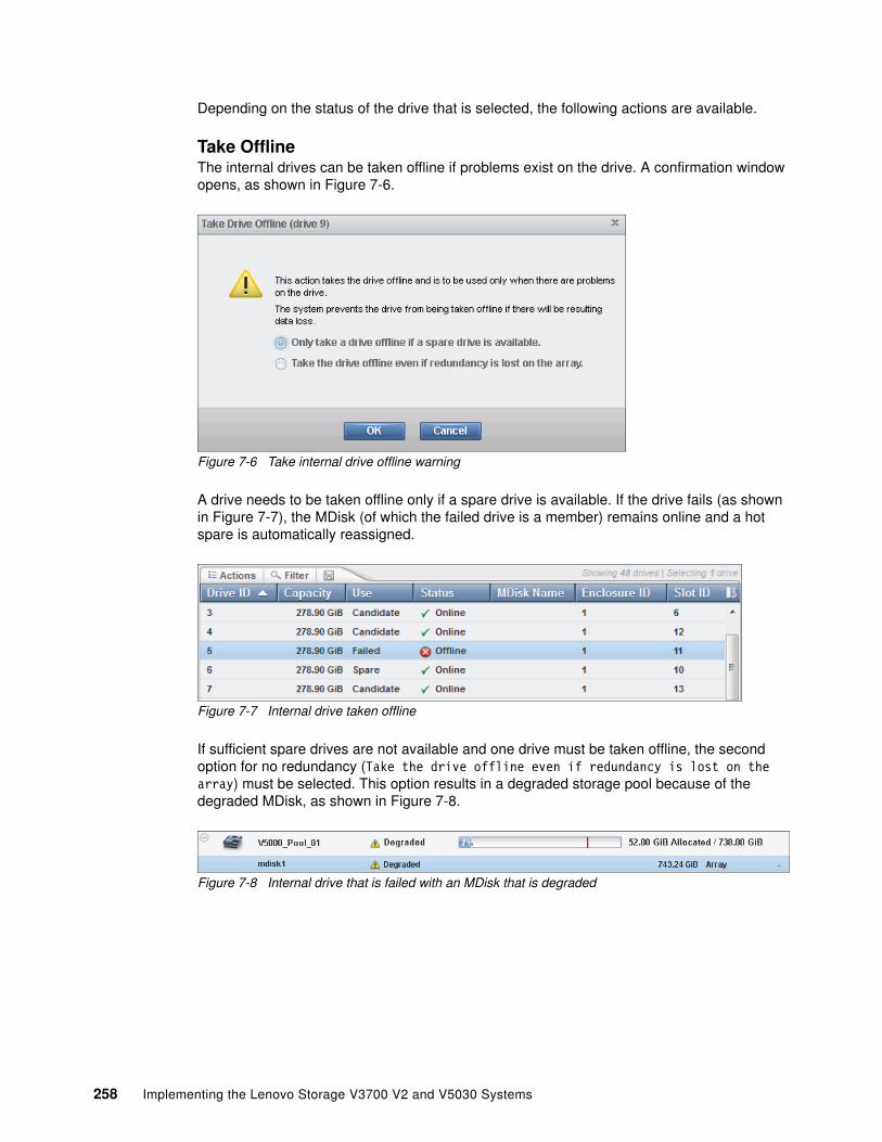
Depending on the status of the drive that is selected, the following actions are available.
Take OfflineThe internal drives can be taken offline if problems exist on the drive. A confirmation window opens, as shown in Figure 7-6.
Figure 7-6 Take internal drive offline warning
A drive needs to be taken offline only if a spare drive is available. If the drive fails (as shown in Figure 7-7), the MDisk (of which the failed drive is a member) remains online and a hot spare is automatically reassigned.
Figure 7-7 Internal drive taken offline
If sufficient spare drives are not available and one drive must be taken offline, the second option for no redundancy (Take the drive offline even if redundancy is lost on the array) must be selected. This option results in a degraded storage pool because of the degraded MDisk, as shown in Figure 7-8.
Figure 7-8 Internal drive that is failed with an MDisk that is degraded
258 Implementing the Lenovo Storage V3700 V2 and V5030 Systems

The Lenovo Storage V3700 V2, V3700 V2 XP, and V5030 storage systems prevent the drive from being taken offline if data loss might result. A drive cannot be taken offline (as shown in Figure 7-9) if no suitable spare drives are available and, based on the RAID level of the MDisk, drives are already offline.
Figure 7-9 Internal drive offline not allowed because of insufficient redundancy
Example 7-1 shows how to use the chdrive command-line interface (CLI) command to set the drive to failed.
Example 7-1 The use of the chdrive command to set the drive to failed
chdrive -use failed driveIDchdrive -use failed -allowdegraded driveID
Chapter 7. Storage pools 259

Mark asThe internal drives in the Lenovo Storage V3700 V2, V3700 V2 XP, and V5030 storage systems can be assigned the following usage roles, as shown in Figure 7-10:
� Unused: The drive is not in use, and it cannot be used as a spare.� Candidate: The drive is available for use in an array.� Spare: The drive can be used as a hot spare, if required.
Figure 7-10 Selecting the internal drive “Mark as” action
The new role that can be assigned depends on the current drive usage role. These dependencies are shown in Figure 7-11.
Figure 7-11 Internal drive usage role table
260 Implementing the Lenovo Storage V3700 V2 and V5030 Systems

IdentifyUse the Identify action to turn on the LED light so that you can easily identify a drive that must be replaced or that you want to troubleshoot. The panel that is shown in Figure 7-12 appears when the LED is on.
Figure 7-12 Internal drive identification
Click Turn LED Off when you are finished.
Example 7-2 shows how to use the chenclosureslot command to turn on and turn off the drive LED.
Example 7-2 The use of the chenclosureslot command to turn on and turn off the drive LED
chenclosureslot -identify yes/no -slot slot enclosureID
UpgradeFrom this option, you can easily upgrade the drive firmware. You can use the GUI to upgrade individual drives or upgrade all drives for which updates are available. For more information about upgrading drive firmware, see 12.4.2, “Updating the drive firmware” on page 611.
Show Dependent VolumesClicking Show Dependent Volumes shows the volumes that depend on the selected drive. Volumes depend on a drive only when their underlying MDisks are in a degraded or inaccessible state and when the removal of more hardware causes the volume to go offline. This condition is true for any RAID 0 MDisk or if the associated MDisk is degraded already.
Use the Show Dependent Volumes option before you perform maintenance to determine the volumes that are affected.
Important: A lack of listed dependent volumes does not imply that no volumes are using the drive.
Chapter 7. Storage pools 261

Figure 7-13 shows an example if no dependent volumes are detected for a specific drive.
Figure 7-13 Internal drive with no dependent volumes
Figure 7-14 shows the list of dependent volumes for a drive when its MDisk is in a degraded state.
Figure 7-14 Internal drive with dependent volumes
262 Implementing the Lenovo Storage V3700 V2 and V5030 Systems

Example 7-3 shows how to view dependent volumes for a specific drive by using the CLI.
Example 7-3 Command to view dependent virtual disks (VDisks) for a specific drive
lsdependentvdisks -drive driveID
PropertiesClicking Properties in the Actions menu or double-clicking the drive provides the vital product data (VPD) and the configuration information, as shown in Figure 7-15. The Show Details option was selected to show more information.
Figure 7-15 First part of internal drive properties
Chapter 7. Storage pools 263

If the Show Details option is not selected, the technical information section is reduced, as shown in Figure 7-16.
Figure 7-16 Internal drives properties no details
A tab for the Drive Slot is available in the Properties panel (as shown in Figure 7-17) to obtain specific information about the slot of the selected drive.
Figure 7-17 Internal drive properties slot
264 Implementing the Lenovo Storage V3700 V2 and V5030 Systems

Example 7-4 shows how to use the lsdrive command to display the configuration information and drive VPD.
Example 7-4 The use of the lsdrive command to display configuration information and drive VPD
IBM_Storwize:ITSO V5000:superuser>lsdrive 1id 1status onlineerror_sequence_numberuse memberUID 5000cca05b1d97b0tech_type sas_hddcapacity 278.9GBblock_size 512vendor_id IBM-E050product_id HUC156030CSS20FRU_part_number 01AC594FRU_identity 11S00D5385YXXX0TGJ8J4PRPM 15000firmware_level J2G9FPGA_levelmdisk_id 0mdisk_name MDisk_01member_id 5enclosure_id 1slot_id 1node_idnode_namequorum_idport_1_status onlineport_2_status onlineinterface_speed 12Gbprotection_enabled yesauto_manage inactivedrive_class_id 145IBM_Storwize:ITSO V5000:superuser>
Chapter 7. Storage pools 265

Customize ColumnsClick Customize Columns in the Actions menu to add or remove several options that are available in the Internal Storage view.
To restore the current view, select Restore Default View, as shown in Figure 7-18.
Figure 7-18 Customizing columns
266 Implementing the Lenovo Storage V3700 V2 and V5030 Systems

7.2 Configuring internal storage
If no Pool is configured, the Lenovo Storage V3700 V2, V3700 V2 XP, and V5030 hint to create pools after the login, as shown in Figure 7-19.
Figure 7-19 Create pools wizard
A pool configuration wizard opens by clicking Create Pools and guides you to the Pools menu. Select the new pool and click Add Storage in the Actions menu, or right-click the pool and select Add Storage, as shown in Figure 7-20.
Figure 7-20 Add Storage by right-clicking the pool
Chapter 7. Storage pools 267

A configuration wizard appears and provides two options as shown in Figure 7-21.
Figure 7-21 Pool configuration
The options are described:
� Quick configuration wizard
This option configures all available drives based on the RAID configuration presets. The setup creates MDisks and pools but it does not create volumes.
If this automated configuration fits your business requirement, we advise that you keep this configuration.
� Advanced configuration wizard
This option starts a wizard to customize the storage configuration. A storage configuration might be customized for the following reasons:
– The automated initial configuration does not meet the client’s requirements.
– More storage was attached to the Lenovo Storage V3700 V2, V3700 V2 XP, and V5030, and it must be integrated into the existing configuration.
268 Implementing the Lenovo Storage V3700 V2 and V5030 Systems

Those configuration options are also available in the Pools → MDisks by Pools menu, as shown in Figure 7-22. Click Add Storage to start this wizard. Click Assign to start the Quick configuration wizard for the specified storage class.
Figure 7-22 Add storage to pools
7.2.1 RAID configuration
In this topic, we describe the Redundant Array of Independent Disks (RAID) configuration and technology.
Introduction to RAID technologyRAID provides two key design goals:
� Increased data reliability� Increased input/output (I/O) performance
When multiple physical disks are set up to use the RAID technology, they are in a RAID array. The Lenovo Storage V3700 V2, V3700 V2 XP, and V5030 provide multiple, traditional RAID levels:
� RAID 0� RAID 1� RAID 5� RAID 6 � RAID 10
Chapter 7. Storage pools 269

RAID technology can provide better performance for data access, high availability for the data, or a combination. RAID levels define a trade-off between high availability, performance, and cost.
The RAID concept must be extended to disk rebuild time because of increasing physical disk capacity.
In a disk failure, traditional RAID writes the data to a single spare drive. With increasing capacity, the rebuild time is increasing and the probability of a second failure during the rebuild process increases, as well. In addition, the spares, when they are not being used, are idle, wasting resources.
Distributed RAID (DRAID) addresses those points and it is available for the Lenovo Storage V3700 V2, V3700 V2 XP, and V5030 in two types:
� Distributed RAID 5 (DRAID 5)� Distributed RAID 6 (DRAID 6)
Distributed RAID reduced the recovery time and reduces the probability of a second failure during rebuild. Just like traditional RAID, a distributed RAID 5 array can lose one physical drive and survive. If another drive fails in the same array before the bad drive is recovered, the MDisk and the storage pool go offline as they did before. So, distributed RAID does not change the general RAID behavior.
Traditional RAID is still supported, and it is the default choice in the GUI.
7.2.2 Distributed RAID
In distributed RAID, all drives are active, which improves performance. Spare capacity is used instead of spare drives. No drives are spare, and all drives contribute to performance. The spare capacity is rotated across the disk drives so the write rebuild load is distributed across multiple drives and the bottleneck of one drive is removed.
270 Implementing the Lenovo Storage V3700 V2 and V5030 Systems
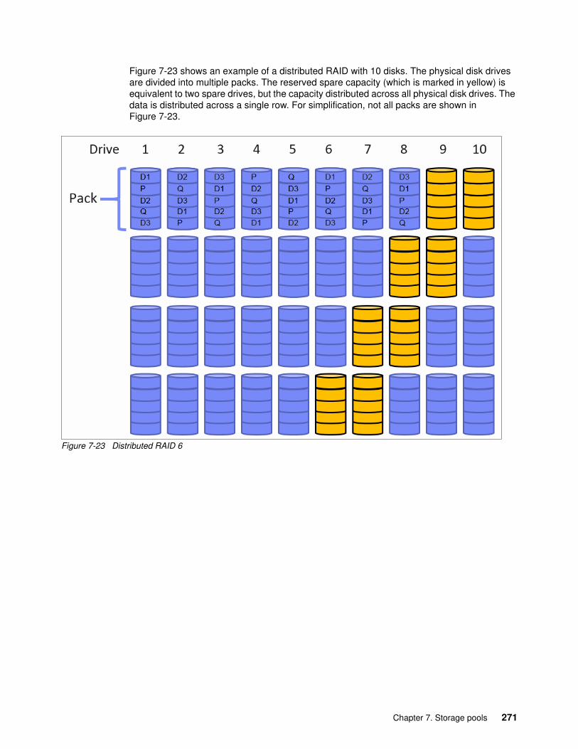
Figure 7-23 shows an example of a distributed RAID with 10 disks. The physical disk drives are divided into multiple packs. The reserved spare capacity (which is marked in yellow) is equivalent to two spare drives, but the capacity distributed across all physical disk drives. The data is distributed across a single row. For simplification, not all packs are shown in Figure 7-23.
Figure 7-23 Distributed RAID 6
Chapter 7. Storage pools 271

Figure 7-24 shows a single drive failure in the distributed RAID 6 (DRAID 6) environment. Physical disk 3 failed and the RAID 6 algorithm is using the spare capacity for a single spare drive in each pack for rebuild (which is marked in green). All disk drives are involved in the rebuild, which significantly reduces the rebuild time. For simplification, not all packs are shown in Figure 7-24.
Figure 7-24 Single drive failure with DRAID 6
The usage of multiple drives for rebuild improves the rebuild process, which is up to 10 times faster than traditional RAID. This speed is important when you use large drives.
The conversion from traditional RAID to distributed RAID is possible by using volume mirroring or volume migration. Mixing traditional RAID and distributed RAID in the same storage pool is possible.
ExampleThe same number of disks can be configured by using traditional or distributed RAID. In our example, we use 38 disk drives and assign those disks as RAID 6 to a single pool.
Figure 7-25 shows the setup for a traditional RAID 6 environment. The pool consists of three MDisks, each with 12 disk drives. The two spare drives are not listed in this summary.
Figure 7-25 Array configuration for a traditional RAID 6 with 38 disks
272 Implementing the Lenovo Storage V3700 V2 and V5030 Systems

Figure 7-26 shows the setup for a distributed RAID 6 environment. The pool consists of a single MDisk with 38 disk drives. The two spare drives are included in this summary.
Figure 7-26 Array configuration for a distributed RAID 6 with 38 disks
7.2.3 RAID configuration presets
RAID configuration presets are used to configure internal drives and they are based on the advised values for the RAID level and drive class. Each preset has a specific goal for the number of drives per array and the number of spare drives to maintain redundancy.
For the best performance with solid-state drives (SSDs), we recommend arrays with the same number of drives, which is the same design for traditional RAID arrays. Distributed RAID with many SSDs is not recommended.
Chapter 7. Storage pools 273

Table 7-1 describes the presets that are used for Flash drives for the Lenovo Storage V3700 V2, V3700 V2 XP, and V5030 storage systems.
Table 7-1 Flash RAID presets
Preset Purpose RAID level
Drives per array goal
Drive count (minimum - maximum)
Spare drive goal
Flash RAID 5
Protects against a single drive failure. Data and one stripe of parity are striped across all array members.
5 8 3 - 16 1
Flash Distributed RAID 5
Protects against a single drive failure. Data and one stripe of parity are striped across all array members.
5 8 3 - 16 1
Flash RAID 6
Protects against two drive failures. Data and two stripes of parity are striped across all array members.
6 12 5 - 16 1
Flash Distributed RAID 6
Protects against two drive failures. Data and two stripes of parity are striped across all array members.
6 12 5 - 16 1
Flash RAID 10
Protects against at least one drive failure. All data is mirrored on two array members.
10 8 4 - 16 (even number of drives)
1
Flash RAID 1
Protects against at least one drive failure. All data is mirrored on two array members.
1 2 2 1
Flash RAID 0
Provides no protection against drive failures.
0 8 1 - 8 0
Flash Easy Tier
Mirrors data to protect against drive failure. The mirrored pairs are spread between storage pools to use for the Easy Tier function.
10 2 4 - 16 (even number of drives)
1
Flash RAID instances: In all Flash RAID instances, drives in the array are balanced across enclosure chains, if possible.
274 Implementing the Lenovo Storage V3700 V2 and V5030 Systems

Table 7-2 describes the RAID presets that are used for Enterprise SAS and Nearline SAS drives for the Lenovo Storage V3700 V2, V3700 V2 XP, and V5030 storage systems.
Table 7-2 Hard disk drive (HDD) RAID presets
7.2.4 Customizing storage configuration
If the storage configuration does not meet the requirements, the pools that are created must first be deleted. Select the Pool navigator in the GUI and click Pools → MDisks by Pools. Select and right-click the pool and select Delete Pool. No confirmation is required any longer.
The MDisks that are associated to the Pool are removed, and the drives become candidate drives. These drives can be used for a different configuration.
Preset Purpose RAID level
Drives per array goal
Drive count (minimum - maximum)
Spare goal Chain balance
BasicRAID 5
Protects against a single drive failure. Data and one stripe of parity are striped across all array members.
5 8 3 - 16 1 All drives in the array are from the same chain wherever possible.
Distributed RAID 5
Protects against a single drive failure. Data and one stripe of parity are striped across all array members.
5 48 - 60 4 - 128 1: 0 - 362: 37 - 723: 73 - 1004: 101 - 128
All drives in the array are from the same chain wherever possible.
Basic RAID 6
Protects against two drive failures. Data and two stripes of parity are striped across all array members.
6 12 5 - 16 1 All drives in the array are from the same chain wherever possible.
Distributed RAID 6
Protects against two drive failures. Data and two stripes of parity are striped across all array members.
6 48 - 60 6 - 128 1: 0 - 362: 37 - 723: 73 - 1004: 101 - 128
All drives in the array are from the same chain wherever possible.
Basic RAID 10
Protects against at least one drive failure. All data is mirrored on two array members.
10 8 4 - 16 (must be an even number of drives)
1 All drives in the arrayare from the samechain wherever possible.
Balanced RAID 10
Protects against at least one drive or enclosure failure. All data is mirrored on two array members. The mirrors are balanced across the two enclosure chains.
10 8 4 - 16 (even) 1 Exactly half of the drives are from each chain.
RAID 0 Provides no protection against drive failures.
0 8 1 - 8 0 All drives in the array are from the same chain wherever possible.
Note: The Delete Pool option is available only when the Pool is not provisioning volumes.
Chapter 7. Storage pools 275

7.2.5 Creating a pool
A pool is required to configure internal storage for use with hosts. Click Pools → MDisks by Pools. Then, click Create Pool, as shown in Figure 7-27, and assign a pool name.
Figure 7-27 Click Create Pool
Warning: When a pool is deleted by using the CLI with the -force parameter, all mappings and any data that is in the pool and any volume that is provisioned from this pool are deleted without any possibility of recovery.
276 Implementing the Lenovo Storage V3700 V2 and V5030 Systems

The new pool is empty, and disk capacity must be assigned. As shown in Figure 7-28, two options are available:
� Add storage by using the configuration wizard� Assign a drive class by using the correct presets
Figure 7-28 Assign storage to pools
Select Add Storage, which guides you through the wizard that is described in 7.2.6, “Add storage to a pool” on page 278.
Or, select Assign, which guides you through the wizard that is described in 7.2.7, “Assign storage to a pool” on page 286.
Chapter 7. Storage pools 277

7.2.6 Add storage to a pool
The configuration wizard opens and guides you through the process of configuring internal storage. As shown in Figure 7-29, the wizard starts with two options.
Figure 7-29 Configuration method
The two configuration options are described:
� Quick configuration wizard:
– This option configures all available drives based on the traditional RAID configuration presets. The setup creates MDisks and assigns them to the selected pool but it does not create volumes.
– If this automated configuration fits your business requirements, we advise that you keep this configuration.
– Select Quick Internal, which guides you through the wizard that is described in “Quick configuration” on page 278.
� Advanced configuration wizard
This option starts a wizard to customize the storage configuration. A storage configuration might be customized for the following reasons:
– The configuration that is proposed by the Quick configuration wizard does not meet your business requirements.
– More storage was attached to the Lenovo Storage V3700 V2, V3700 V2 XP, and V5030, and it must be integrated in the existing configuration.
– Select Advanced Internal Custom, which guides you through the wizard that is described in “Advanced configuration” on page 282.
Quick configuration All disk drives that are selected in this wizard are assigned to the previously selected pool.
The configuration can be adapted according to your requirements by these methods:
� Selecting the drive class� Setting the number of disk drives � Selecting a combination of multiple drive classes for an Easy Tier configuration
278 Implementing the Lenovo Storage V3700 V2 and V5030 Systems

These parameters can be changed by setting the number of disk drives as required. Figure 7-30 shows an example of an enterprise pool, which consists of 24 disk drives, although 36 disk drives are available. The system shows the configuration details at the bottom of the window. All configuration changes are based on traditional RAID. Distributed RAID must be configured by using the Advanced configuration wizard.
Figure 7-30 Quick configuration: Single disk drive class
Chapter 7. Storage pools 279

Multiple disk classes can be assigned to the same pool. This setting is the default. By selecting multiple disk classes, you create an Easy Tier pool, as shown in Figure 7-31.
Figure 7-31 Quick configuration: Easy Tier pool
280 Implementing the Lenovo Storage V3700 V2 and V5030 Systems

The wizard can be used to add more capacity to existing pools by adding disk drives with the same or different drive classes, as shown in Figure 7-32.
Figure 7-32 Quick configuration: Add more capacity
Spare drives in the Lenovo Storage V3700 V2, V3700 V2 XP, and V5030 are global spares, which means that any spare drive that has at least the same capacity as the drive that is replaced can be used in any array. Therefore, a Flash array with no available Flash spare uses a SAS spare instead.
Spare drives are automatically created to meet the spare goals according to the chosen preset. They are not created if sufficient spares are configured.
After an array is created, the Array MDisk members are synchronized with each other through a background initialization process. The progress of the initialization process can be monitored by clicking the icon at the left of the Running Tasks status bar and selecting the initialization task to view the status, as shown in Figure 7-33.
Figure 7-33 Running Tasks panel
Chapter 7. Storage pools 281

Click the taskbar to open the progress window, as shown in Figure 7-34. The array is available for I/O during this process.
Figure 7-34 Initialization progress view
Advanced configurationUse the Advanced configuration if disk drives that are selected in this wizard are assigned to the previously selected pool.
The configuration can be adapted according to the requirements by the following methods:
� Selecting the drive class� Setting the number of disk drives � Selecting the RAID level (traditional and distributed RAID)� Defining the number of spare drives� Setting the array width
282 Implementing the Lenovo Storage V3700 V2 and V5030 Systems

Figure 7-35 shows an example in which 38 drives are ready to be configured as distributed RAID 6. The capacity of two disks is automatically assigned as spare capacity. If spare disks are defined in this drive class, the system does not assign additional spare capacity during capacity assignment. The small, red highlighted Summary icon that is shown in Figure 7-35 opens a page that shows the expected configuration changes.
Figure 7-35 Configuration of a distributed RAID 6
Chapter 7. Storage pools 283

The Summary page, which is shown in Figure 7-36, shows the expected configuration changes. The red highlighted Drive Assignment option changes the view back to the Drive Assignment section.
Figure 7-36 Summary of the expected configuration
You can add more disk drives to the same pool by running the same wizard again and by using the same pool.
Spare drives in the Lenovo Storage V3700 V2, V3700 V2 XP, and V5030 are global spares, which means that any spare drive that has at least the same capacity as the drive to be replaced can be used in any array. Therefore, a Flash array with no available Flash spare uses a SAS spare instead.
Spare drives are automatically created to meet the spare goals according to the chosen preset. They are not created if sufficient spares are configured.
284 Implementing the Lenovo Storage V3700 V2 and V5030 Systems

After an array is created, the Array MDisk members are synchronized with each other through a background initialization process. The progress of the initialization process can be monitored by clicking the icon at the left of the Running Tasks status bar and selecting the initialization task to view the status, as shown in Figure 7-37.
Figure 7-37 Running Tasks panel
Click the taskbar to open the progress window, as shown in Figure 7-38. The array is available for I/O during this process.
Figure 7-38 Initialization progress view
Chapter 7. Storage pools 285

7.2.7 Assign storage to a pool
A pool is required for a storage assignment. More details about pool creation are available in 7.2.5, “Creating a pool” on page 276. You can assign the disk to the pool by clicking Pool → MDisks by Pools and by selecting Assign (marked in red), as shown in Figure 7-39.
Figure 7-39 Disk assignment to a pool
Two options are available:
� Select the pool for disk assignment� Modify the number of disk drives that are assigned to the pool
All RAID is defined automatically according to the traditional RAID presets that are described in 7.2.3, “RAID configuration presets” on page 273. Currently, distributed RAID cannot be used within this wizard. The expected configuration is shown at the bottom of the window.
286 Implementing the Lenovo Storage V3700 V2 and V5030 Systems

Figure 7-40 shows an example of how to assign 24 out of 36 disk drives to an existing pool.
Figure 7-40 Assign disk to a pool
You can add more disk drives to the same pool by running the same wizard again, as shown in Figure 7-41.
Figure 7-41 Assignment of a second storage class to a pool
Chapter 7. Storage pools 287

Spare drives in the Lenovo Storage V3700 V2, V3700 V2 XP, and V5030 are global spares, which means that any spare drive that has at least the same capacity as the drive to be replaced can be used in any array. Therefore, a Flash array with no Flash spare available uses a SAS spare instead.
Spare drives are automatically created to meet the spare goals according to the preset chosen. They are not created if sufficient spares are configured.
After an array is created, the Array MDisk members are synchronized with each other through a background initialization process. The progress of the initialization process can be monitored by clicking the icon at the left of the Running Tasks status bar and selecting the initialization task to view the status, as shown in Figure 7-42.
Figure 7-42 Running Tasks panel
Click the taskbar to open the progress window, as shown in Figure 7-43. The array is available for I/O during this process.
Figure 7-43 Initialization progress view
288 Implementing the Lenovo Storage V3700 V2 and V5030 Systems

7.2.8 More actions on MDisks
The following actions can be performed on MDisks:
� Discover storage
The Discover storage option in the upper left of the MDisks by Pools window is useful if external storage controllers are in your environment. (For more information, see Chapter 11, “External storage virtualization” on page 549.) The Discover storage action starts a rescan of the Fibre Channel network. It discovers any new MDisks that were mapped to the Lenovo Storage V3700 V2, V3700 V2 XP, and V5030 storage systems and rebalances MDisk access across the available controller device ports.
This action also detects any loss of controller port availability and updates the Lenovo Storage V3700 V2, V3700 V2 XP, and V5030 configuration to reflect any changes.
When external storage controllers are added to the Lenovo Storage V3700 V2, V3700 V2 XP, and V5030 environment, the Lenovo Storage V3700 V2, V3700 V2 XP, and V5030 automatically discover the controllers, and the logical unit numbers (LUNs) that are presented by those controllers are listed as unmanaged MDisks.
However, if you attached new storage and the Lenovo Storage V3700 V2, V3700 V2 XP, and V5030 did not detect it, you might need to use the Discover storage option before the system detects the new LUNs. If the configuration of the external controllers is modified afterward, the Lenovo Storage V3700 V2, V3700 V2 XP, and V5030 might be unaware of these configuration changes. Use Detect MDisk to rescan the Fibre Channel network and update the list of unmanaged MDisks.
Figure 7-44 shows the Discover storage option.
Figure 7-44 Discover storage
� Include Excluded MDisks
An MDisk can be excluded from the Lenovo Storage V3700 V2, V3700 V2 XP, and V5030 because of multiple I/O failures. These failures might be caused, for example, by link errors. After a fabric-related problem is fixed, the excluded disk can be added back into the Lenovo Storage V3700 V2, V3700 V2 XP, and V5030 by selecting the MDisks and clicking Include Excluded MDisk from the Actions drop-down menu.
Discover storage detection: The Discover storage action is asynchronous. Although the task appears to be finished, it might still be running in the background.
Chapter 7. Storage pools 289

� Select Tier
The Lenovo Storage V3700 V2, V3700 V2 XP, and V5030 automatically assign tiers to internal drives and external MDisks. The tier of an internal MDisk cannot be changed, but if the disk tier of an external MDisk is recognized incorrectly, use this option to manually change the disk tier. To specify a new tier, select the MDisk and click Actions → Select Tier, as shown in Figure 7-45.
Figure 7-45 Select the disk tier that you want
Other actions are available by clicking MDisk by Pool → Actions, as shown in Figure 7-46.
Figure 7-46 MDisk actions on externally virtualized storage
290 Implementing the Lenovo Storage V3700 V2 and V5030 Systems
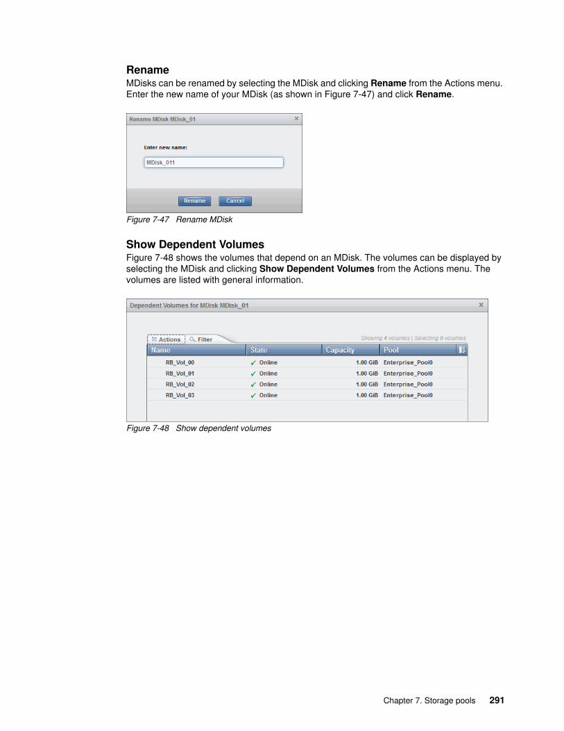
RenameMDisks can be renamed by selecting the MDisk and clicking Rename from the Actions menu. Enter the new name of your MDisk (as shown in Figure 7-47) and click Rename.
Figure 7-47 Rename MDisk
Show Dependent VolumesFigure 7-48 shows the volumes that depend on an MDisk. The volumes can be displayed by selecting the MDisk and clicking Show Dependent Volumes from the Actions menu. The volumes are listed with general information.
Figure 7-48 Show dependent volumes
Chapter 7. Storage pools 291

PropertiesThe Properties action for an MDisk shows the information that you need to identify it. In the MDisks by Pools window, select the MDisk and click Properties from the Actions menu. The following tabs are available in this information window:
� The Overview tab (as shown in Figure 7-49) contains information about the MDisk. To show more details, click View more details.
Figure 7-49 MDisk properties
292 Implementing the Lenovo Storage V3700 V2 and V5030 Systems

� The Member Drives tab, as shown in Figure 7-50, shows all of the member drives of this MDisk. Also, all actions that are described in 7.1.2, “Actions on internal drives” on page 257 can be performed on the drives that are listed on this tab.
Figure 7-50 MDisk member drives
7.3 Working with storage pools
The next sections provide a detailed overview about the concept and use of the storage pools and child pools.
Storage pools (or pools) act as containers for MDisks and provision the capacity to volumes. Lenovo Storage V3700 V2, V3700 V2 XP, and V5030 organize storage into storage pools to ease storage management and make it more efficient. Child pools act as subcontainers and inherit the parent storage pool’s properties, and they can also be used to provision capacity to volumes.
Chapter 7. Storage pools 293

Storage pools and MDisks are managed through the MDisks by Pools window. You can access the MDisks by Pools window by clicking Overview → Pools, which is available at Monitoring → System. Both options are highlighted in red in Figure 7-51.
Figure 7-51 Selecting the Pools icon from the Overview window
An alternative path to the Pools window is to click Pools → MDisks by Pools, as shown in Figure 7-52.
Figure 7-52 Accessing pools from the MDisk by Pools window
294 Implementing the Lenovo Storage V3700 V2 and V5030 Systems

By using the MDisks by Pools window, as shown in Figure 7-53, you can manage internal and external storage pools. All existing storage pools are displayed row-by-row. The first row shows unassigned MDisks and contains all unmanaged MDisks, if any exist. Each defined storage pool is displayed with its assigned icon and name, numerical ID, status, and a graphical indicator that shows the percentage of the pool’s capacity that is allocated to volumes.
Figure 7-53 Pools window
When you expand a pool’s entry by clicking the plus sign (+) to the left of the pool’s icon, you can access the MDisks that are associated with this pool. You can perform all of the actions on them.
7.3.1 Create Pool option
Storage pools are required for capacity assignment. To create an empty pool, click the New Pool option in the MDisks by Pools window. The only required parameter for the pool is the pool name, as shown in Figure 7-54.
Figure 7-54 Enter a pool name
Chapter 7. Storage pools 295

The Lenovo Storage V3700 V2, V3700 V2 XP, and V5030 GUI has a default extent size value of 1 GiB when you define a storage pool. Therefore, if you are creating an empty pool by using the GUI and you want to specify the size of the extents, you must ensure that the Advanced pool settings option is selected in Settings → GUI Preferences. The size of the extent is selected at creation, and it cannot be changed later. Figure 7-55 shows an example of how to create a pool and how to choose an extent size.
Figure 7-55 Creating a pool and choosing the extent size
The new pool is included in the pool list with 0 bytes, as shown in Figure 7-56.
Figure 7-56 Creating an empty pool
296 Implementing the Lenovo Storage V3700 V2 and V5030 Systems

7.3.2 Actions on storage pools
Several actions that can be performed on storage pools by using the Actions menu, as shown in Figure 7-57.
Figure 7-57 Pool Actions menu
Rename the storage poolThe storage pool can be renamed at any time, as shown in Figure 7-58.
Figure 7-58 Rename a storage pool
Chapter 7. Storage pools 297

Modify the pool thresholdA warning is generated the first time that the threshold is exceeded by the used-disk capacity in the storage pool. The threshold can be modified by using a percentage of the storage pool. The default threshold is 80%, as shown in Figure 7-59. Warnings can be disabled by setting the threshold to 0%.
Figure 7-59 Pool threshold modification
Add storage to a poolSelecting Add Storage guides you through the wizard that is described in 7.2.6, “Add storage to a pool” on page 278.
Delete a storage poolPools can be deleted by using the GUI only if no volumes are assigned to the pool. The option is not available if volumes are in the pool. The pool is deleted immediately without additional confirmation.
Through the CLI, you can delete a pool and all of its contents by using the -force parameter. However, all volumes and host mappings are deleted, and you cannot recover them.
After you delete the pool, all of the managed or image mode MDisks in the pool return to a status of unmanaged.
Important: After you delete the pool through the CLI, all data that is stored in the pool is lost except for the image mode MDisks. The image mode MDisk volume definition is deleted, but the data on the imported MDisk remains untouched.
298 Implementing the Lenovo Storage V3700 V2 and V5030 Systems

Pool propertiesThe pool properties are displayed. Additional information is available by moving the mouse across the indicator, as shown in Figure 7-60.
Figure 7-60 Pool properties
By clicking View more details, more pool details are visible, as shown in Figure 7-61.
Figure 7-61 Pool properties in detail
Create a child poolA child pool is a storage pool within a storage pool (parent pool). Child pools are used to provide the capacity of the parent pool without volume usage. For example, they are used with VMware Virtual Volumes (VVols) to provide pool functionality for VMware vSphere Server. The VMware vSphere Server manages the volumes within the child pool. However, you must not manage child pools for the VVol environment by using the Lenovo Storage V3700 V2, V3700 V2 XP, and V5030 GUI.
Chapter 7. Storage pools 299

A storage parent pool is a collection of MDisks that provide the pool of storage from which volumes are provisioned. A child pool exists in and gets capacity exclusively from one storage pool. A user can specify the child pool capacity at creation. The child pool can grow and decrease nondisruptively.
The child pool shares the properties of the parent storage pool and provides most of the functions of storage pools. The following properties and behaviors are common:
� ID, name, status, and volume count � Warning thresholds (Child pools can have their own threshold warning setting.)� MDisk (This value is always zero for child pools.)� Space utilization (in a percentage (%))� Easy Tier (For a child pool, this value must be the same as the parent Mdiskgrp’s Easy
Tier setting.)
Because a child pool must have a unique parent pool, the maximum number of child pools per parent pools is 127.
Figure 7-62 shows an example of a child pool.
Figure 7-62 Child pool representation
Note: The capacity of the child pool is always limited to the free capacity of the parent pool.
300 Implementing the Lenovo Storage V3700 V2 and V5030 Systems

For child pool creation, the parent pool must be selected. After you click Actions → Create Child Pool, you must enter the name and capacity of the child pool, as shown in Figure 7-63.
Figure 7-63 Child pool creation
The list of pools and associated child pools is available at Pools → Pools, as shown in Figure 7-64.
Figure 7-64 List of pools and associated child pools
You cannot create a child pool in a child pool. All other actions that were described for pools (Rename, Modify Threshold, Add Storage, Delete, and Properties) are available for child pools, also.
For more information about the limits and restrictions, see the following URL:
http://systemx.lenovofiles.com/mobile/help/topic/com.lenovo.storage.v3700.doc/svc_mdiskgroupovr_1bchdu.html
Chapter 7. Storage pools 301

Resize a child poolA child pool can be easily expanded and reduced. Right-click the child pool in the Pools → Pools menu and select Resize, as shown in Figure 7-65.
Figure 7-65 Resize child pool
Enter the new child pool capacity. A warning appears if the capacity of the new child pool is lower than the capacity in use, as shown in Figure 7-66. The Lenovo Storage V3700 V2, V3700 V2 XP, and V5030 automatically adjust the new capacity to the minimum required capacity.
Figure 7-66 Set new child pool size
302 Implementing the Lenovo Storage V3700 V2 and V5030 Systems

7.4 Working with MDisks on external storage
After the internal storage configuration is complete, you can find the MDisks that were created by using the internal drives in the MDisks by Pools window. When you use this window, you can manage all MDisks that are made up of internal and external storage.
Logical unit numbers (LUNs) that are presented by external storage systems to Lenovo Storage V3700 V2, V3700 V2 XP, and V5030 are discovered as unmanaged MDisks. Initially, the MDisk is not a member of any storage pools, which means that it is not used by the Lenovo Storage V3700 V2, V3700 V2 XP, and V5030 storage systems.
To learn more about external storage, see Chapter 11, “External storage virtualization” on page 549.
Chapter 7. Storage pools 303

304 Implementing the Lenovo Storage V3700 V2 and V5030 Systems

Chapter 8. Advanced host and volume administration
The Lenovo Storage V3700 V2, V3700 V2 XP, and V5030 offer many functions for volume and host configuration. The basic host and volume features of the Lenovo Storage V3700 V2, V3700 V2 XP, and V5030 are described in Chapter 4, “Host configuration” on page 139 and Chapter 5, “Volume configuration” on page 189. The chapters also describe how to create hosts and volumes and how to map them to a host.
This chapter focuses on advanced host and volume administration topics. The first part of it describes the following host administration topics:
� 8.1, “Advanced host administration” on page 306� 8.2, “Adding and deleting host ports” on page 320� 8.3, “Host mappings overview” on page 326
The second part of the chapter consists of the following volume-related tasks:
� 8.4, “Advanced volume administration” on page 328� 8.5, “Volume properties and volume copy properties” on page 344� 8.6, “Advanced volume copy functions” on page 347� 8.7, “Volumes by storage pool” on page 355� 8.8, “Volumes by host” on page 356
8
© Copyright Lenovo 2018. All rights reserved. 305

8.1 Advanced host administration
This section describes advanced host administration, including host modification, host mappings, and deleting hosts. Basic host creation and mapping are described in Chapter 4, “Host configuration” on page 139. We assume that hosts are defined and volumes are mapped to them.
The following topics are covered in this section:
� Modifying hosts, as described in 8.1.1, “Modifying volume mappings” on page 308� Ports by host, as described in 8.2, “Adding and deleting host ports” on page 320� Host mappings, as described in 8.3, “Host mappings overview” on page 326
The top-level Hosts menu is shown in Figure 8-1.
Figure 8-1 Hosts menu
Note: To clearly highlight the selected menu options, we set Animated navigation dock to Enabled under the Settings → GUI Preferences → Navigation menu.
306 Implementing the Lenovo Storage V3700 V2 and V5030 Systems

Select Hosts to open the Hosts panel, as shown in Figure 8-2.
Figure 8-2 Hosts panel
Figure 8-2 shows several hosts with the volumes that are mapped to them all.
Select a host and click Actions (as shown in Figure 8-3) or right-click the host to show the available actions.
Figure 8-3 Actions menu on the Hosts panel
As shown in Figure 8-3, several actions are associated with host mapping. For more information, see 8.1.1, “Modifying volume mappings” on page 308 and 8.1.2, “Unmapping volumes from a host” on page 311.
Chapter 8. Advanced host and volume administration 307

8.1.1 Modifying volume mappings
From the Hosts panel, after you select a host and click Actions, select Modify Volume Mappings to open the Modify Host Mappings panel, as shown in Figure 8-4.
Figure 8-4 Host mappings panel
If the system has multiple I/O groups, a drop-down menu in the upper left of the panel shows the I/O group selection. When you select individual I/O groups, the Lenovo Storage V3700 V2, V3700 V2 XP, and V5030 GUI list only the volumes that correspond to that I/O group.
The Host drop-down menu lists the hosts that are attached to the Lenovo Storage V3700 V2, V3700 V2 XP, and V5030 so you can change the host for which you want to modify the volume mapping, as shown in Figure 8-5.
Figure 8-5 Select a host to modify
Important: Before you change host mappings, always ensure that the host can access volumes from the correct I/O group.
308 Implementing the Lenovo Storage V3700 V2 and V5030 Systems

The left pane (Unmapped Volumes) shows the volumes that are available for mapping to the chosen host. The right pane (Volumes Mapped to the Host) shows the volumes that are already mapped. Figure 8-4 on page 308 shows that the volumes that are named volume_0 with SCSI ID 0 and volume_1 with SCSI ID 1 are mapped to the host Host_1. The left pane shows that two more volumes (volume_2 and volume_3) are available for mapping.
To map more volumes to a chosen host, select one or more volumes from the left pane, as shown in Figure 8-6, then click the right arrows icon (>>) to move the volumes to the right pane, as shown in Figure 8-7. The changes are highlighted in yellow and the Map Volumes and Apply options are enabled.
Figure 8-6 Modify Host Mappings: Select volumes to map
Figure 8-7 Modify Host Mappings: Map volumes to the host
Important: The Unmapped Volumes section refers to volumes that are not mapped to the chosen host. However, they might be mapped to other hosts.
Chapter 8. Advanced host and volume administration 309

After you move a volume to the right pane in the Modify Host Mappings panel, you can right-click the yellow unmapped volume and change the Small Computer System Interface (SCSI) ID that is used for the host mapping, as shown in Figure 8-8.
Figure 8-8 Editing the SCSI ID
Click Edit SCSI ID, select the required SCSI ID, then click OK to save the change. Click Apply to submit the changes and complete the host volume mapping.
Clicking Map Volumes applies the changes and the Modify Mappings task completion dialog shows that the task is completed successfully, as shown in Figure 8-9. Check the task status and click Close to close the dialog.
Figure 8-9 Modify mappings task completed
Important: The Lenovo Storage V3700 V2, V3700 V2 XP, and V5030 automatically assign the lowest available SCSI ID if none is specified. However, you can set a SCSI ID for the volume. The SCSI ID cannot be changed while the volume is assigned to the host.
Note: The task completion dialog stays on the window if the task finished with errors or if the “View more details” link was clicked, as shown in Figure 8-9.
310 Implementing the Lenovo Storage V3700 V2 and V5030 Systems

If Apply was clicked in the panel that is shown in Figure 8-7 on page 309, the changes are submitted to the system, but the Modify Host Mappings panel remains open for more changes.
Also, you can map a volume to multiple hosts. However, you typically map a volume to multiple hosts only in a clustered host environment because data can become corrupted. A warning is displayed, as shown in Figure 8-10.
Figure 8-10 Warning that a volume is mapped to multiple hosts
After you click Close, the Modify Host Mappings panel closes.
8.1.2 Unmapping volumes from a host
To unmap a volume from a host, click Hosts → Actions → Modify Volume Mappings to open the Modify Host Mappings panel. Select the volume and click the left arrows icon (<<) to move the volume to the left (Unmapped Volumes) pane. Multiple volumes can be unmapped by selecting them with the Ctrl key or Shift key, as shown in Figure 8-11.
Figure 8-11 Unmapping volumes
Chapter 8. Advanced host and volume administration 311

To unmap all volumes from a host, select a host from the Hosts panel and click Actions → Unmap all Volumes, as shown in Figure 8-12.
Figure 8-12 Unmap all volumes
A prompt is displayed that requests confirmation of the number of mappings to remove. Enter the number of mappings to remove and click Unmap. In the example, four mappings are removed, as shown in Figure 8-13.
Figure 8-13 Enter the number of mappings to remove
Unmapping: By clicking Unmap, access to all of the volumes for this host is removed. Ensure that the required procedures are run on the host operating system (OS) before you unmap the volumes from the host.
312 Implementing the Lenovo Storage V3700 V2 and V5030 Systems

After you click Unmap, the changes are applied to the system, as shown in Figure 8-14. If the task completion dialog stays open, click Close after you review the output.
Figure 8-14 Unmapping all volumes from the host
Figure 8-15 shows that the selected host is not mapped to any volumes.
Figure 8-15 Host mapping
Chapter 8. Advanced host and volume administration 313

8.1.3 Renaming a host
To rename a host, go to the Hosts panel, and select the host. Click Actions → Rename, as shown in Figure 8-16.
Figure 8-16 Renaming a host
Enter a new name and click Rename, as shown in Figure 8-17. If you click Reset, you change the host name back to its original name. Click Cancel if you decide to cancel the name change and close the Rename Host panel.
Figure 8-17 Rename Host panel
After the changes are applied to the system, if the task completion dialog stays open, review the results and click Close, as shown in Figure 8-18.
Figure 8-18 Rename a host task completed
314 Implementing the Lenovo Storage V3700 V2 and V5030 Systems

8.1.4 Removing a host
To remove a host, go to the Hosts panel, and select the host. From the Actions menu, click Remove, as shown in Figure 8-19.
Figure 8-19 Removing a host
A prompt is displayed that requests that you confirm the number of hosts to remove. Enter the number of hosts that you want to remove and click Remove, as shown in Figure 8-20.
Figure 8-20 Removing a host
If it is necessary to remove a host with assigned volumes, select Remove the hosts even if volumes are mapped to them. These volumes will no longer be accessible to the hosts to force the action. See Figure 8-20.
Chapter 8. Advanced host and volume administration 315
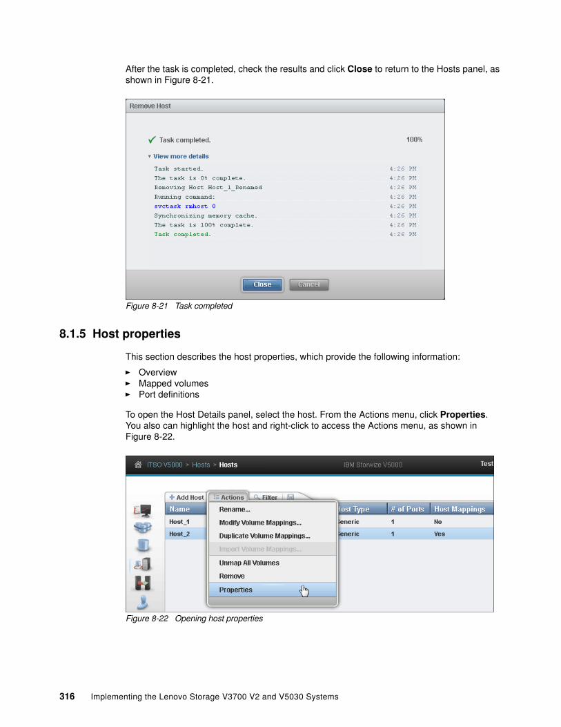
After the task is completed, check the results and click Close to return to the Hosts panel, as shown in Figure 8-21.
Figure 8-21 Task completed
8.1.5 Host properties
This section describes the host properties, which provide the following information:
� Overview� Mapped volumes� Port definitions
To open the Host Details panel, select the host. From the Actions menu, click Properties. You also can highlight the host and right-click to access the Actions menu, as shown in Figure 8-22.
Figure 8-22 Opening host properties
316 Implementing the Lenovo Storage V3700 V2 and V5030 Systems
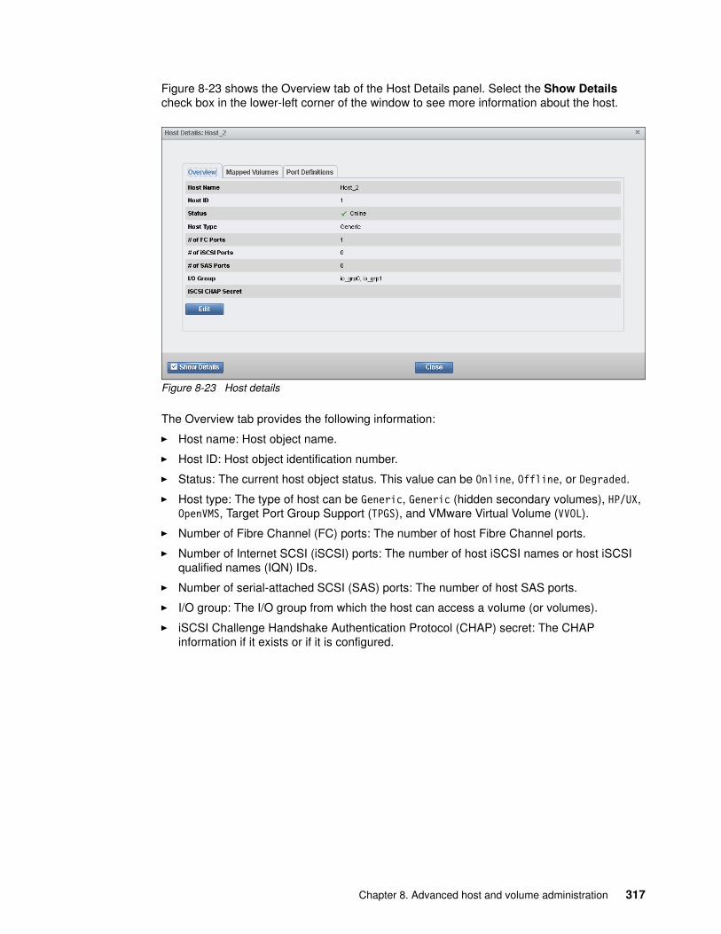
Figure 8-23 shows the Overview tab of the Host Details panel. Select the Show Details check box in the lower-left corner of the window to see more information about the host.
Figure 8-23 Host details
The Overview tab provides the following information:
� Host name: Host object name.
� Host ID: Host object identification number.
� Status: The current host object status. This value can be Online, Offline, or Degraded.
� Host type: The type of host can be Generic, Generic (hidden secondary volumes), HP/UX, OpenVMS, Target Port Group Support (TPGS), and VMware Virtual Volume (VVOL).
� Number of Fibre Channel (FC) ports: The number of host Fibre Channel ports.
� Number of Internet SCSI (iSCSI) ports: The number of host iSCSI names or host iSCSI qualified names (IQN) IDs.
� Number of serial-attached SCSI (SAS) ports: The number of host SAS ports.
� I/O group: The I/O group from which the host can access a volume (or volumes).
� iSCSI Challenge Handshake Authentication Protocol (CHAP) secret: The CHAP information if it exists or if it is configured.
Chapter 8. Advanced host and volume administration 317

To change the host properties, click Edit. Several fields can be edited, as shown in Figure 8-24.
Figure 8-24 Host properties: Editing the host information
For the host type, choose one of these values: Generic, Generic (hidden secondary volumes), HP/UX, OpenVMS, TPGS, or VVOL.
After you change any host information, click Save to apply your changes.
318 Implementing the Lenovo Storage V3700 V2 and V5030 Systems

Figure 8-25 shows the Mapped Volumes tab, which provides an overview of the volumes that are mapped to the host. This tab provides the following information:
� SCSI ID� Volume name� Unique identifier (UID)� Caching I/O group ID
Clicking the Show Details option does not show any detailed information.
Figure 8-25 Host Details: Mapped Volumes tab
Figure 8-26 shows the Port Definitions tab, which shows the configured host ports and their status. This tab provides the following information:
� Name: The worldwide port names (WWPNs) (for SAS and FC hosts) or iSCSI Qualified Name (IQN) for iSCSI hosts
� Type: Port type
� Status: Current port status
� Number of nodes that are logged in: Lists the number of Lenovo Storage V3700 V2, V3700 V2 XP, and V5030 node canisters that each port (initiator port) is logged in to
Figure 8-26 Host port definitions
Chapter 8. Advanced host and volume administration 319

By using this panel, you can also add and delete host ports, as described in 8.2, “Adding and deleting host ports” on page 320.
Selecting the Show Details option does not show any information.
Click Close to close the Host Details panel.
8.2 Adding and deleting host ports
To configure host ports, click Hosts → Ports by Host, as shown in Figure 8-27, to open the Ports by Host panel.
Figure 8-27 Ports by Host menu option
320 Implementing the Lenovo Storage V3700 V2 and V5030 Systems

In the Ports by Host panel, hosts are listed in the left pane, as shown in Figure 8-28. The host icons show an orange cable for a Fibre Channel host, a black cable for a SAS host, and a blue cable for an iSCSI host.
The properties of the selected host are shown in the right pane. Click Add Host to start the wizard that is described in Chapter 4, “Host configuration” on page 139.
Figure 8-28 shows the Actions menu and the associated tasks for a host.
Figure 8-28 Ports by Host Actions menu
8.2.1 Adding a host port
To add a host port, select the host from left pane, click Add, and then choose a port type that is available on the storage system (Fibre Channel port, SAS port, or iSCSI port), as shown in Figure 8-29.
Figure 8-29 Adding a host port
Important: A host system can mix Fibre Channel, iSCSI, and SAS connections. If a configuration requires a mixture of protocols, check the capabilities of the OS and plan carefully to avoid miscommunication or data loss.
Chapter 8. Advanced host and volume administration 321

8.2.2 Adding a Fibre Channel port
Click Add, as shown in Figure 8-29 on page 321, then click Fibre Channel Port to open the Add Fibre Channel Ports panel.
Click the Fibre Channel Ports list box to display a list of all available Fibre Channel host ports. If the FC WWPN of your host is not available in the list, check the storage area network (SAN) zoning and rescan the SAN from the host or click Rescan.
Select the required WWPN and click Add Port to List to add the port to the Port Definitions list, as shown in Figure 8-30. Repeat this step to add more ports to the host.
Figure 8-30 Adding online host ports
322 Implementing the Lenovo Storage V3700 V2 and V5030 Systems

To add an offline port manually, enter the WWPN of the port into the Fibre Channel Ports field and click Add Port to List, as shown in Figure 8-31.
Figure 8-31 Adding an offline port
The port appears as unverified because it is not logged in to the SAN fabric or not known to the Lenovo Storage V3700 V2, V3700 V2 XP, and V5030 systems. The first time that the port logs in, its state automatically changes to online. The mapping is applied to this port.
To remove one of the ports from the list, click the red X to the right of the port definition.
Click Add Ports to Host to apply the changes.
8.2.3 Adding a SAS host port
Click Add, as shown in Figure 8-29 on page 321, and click SAS Port to open the Add SAS Ports panel.
Click the SAS Ports drop-down list to see a list of all available SAS ports. If the SAS WWPNs are not available, click Rescan or check the physical connections.
Important: When you remove online ports or offline ports, the Lenovo Storage V3700 V2, V3700 V2 XP, and V5030 prompt you to confirm the number of ports to delete but it does not warn you about mappings. Disk mapping is associated to the host object, and logical unit number (LUN) access is lost if all ports are deleted.
Important: The Lenovo Storage V3700 V2, V3700 V2 XP, and V5030 allow the addition of an offline SAS port. Enter the SAS WWPN in the SAS Ports field and click Add Port to List.
Chapter 8. Advanced host and volume administration 323

Select the required SAS WWPN and click Add Port to List, as shown in Figure 8-32. Repeat this step to add more ports to a host.
Figure 8-32 Adding an online SAS port
Click Add Ports to Host to apply the changes.
8.2.4 Adding an iSCSI host port
After you click Add, as shown in Figure 8-29 on page 321, select iSCSI Port to open the Add iSCSI Ports panel (Figure 8-33).
Figure 8-33 Adding iSCSI host ports
324 Implementing the Lenovo Storage V3700 V2 and V5030 Systems

Enter the initiator name of your host and click Add Port to List, as shown in Figure 8-33 on page 324. Click Add Ports to Host to apply the changes. The iSCSI port status remains unknown until it is added to the host and a host rescan process completes.
Click Close to return to the Ports by Host panel.
8.2.5 Deleting a host port
To delete host ports, click Hosts → Ports by Host to open the Ports by Host panel, as shown in Figure 8-27 on page 320.
Choose the host in left pane and select the host port to delete, then click Delete Port, as shown in Figure 8-34.
Figure 8-34 Delete the host port
Multiple ports can be selected by holding down the Ctrl and Shift keys while you select the host ports to delete.
Important: An error message with code CMMVC6581E is shown if one of the following conditions occurs:
� The IQNs exceed the maximum number that is allowed.� A duplicate IQN exists.� The IQN is invalid.
Chapter 8. Advanced host and volume administration 325

Figure 8-35 shows the Delete Ports confirmation dialog. Verify the number of ports to delete and click Delete to apply the changes.
Figure 8-35 Delete host port
If a task panel opens to show the results, review the task message output and click Close to return to the Ports by Host panel.
8.3 Host mappings overview
Select Hosts → Host Mappings (Figure 8-36) to open the Host Mappings panel, as shown in Figure 8-37 on page 327.
Figure 8-36 Host Mappings
326 Implementing the Lenovo Storage V3700 V2 and V5030 Systems

The Host Mappings panel shows a list of mapped hosts and volumes with their SCSI IDs, volume unique identifiers (UIDs), and caching I/O Group IDs.
Figure 8-37 shows Host_1 with two mapped volumes (volume_0 and volume_1), associated SCSI IDs (0 and 1), UIDs, and caching I/O group IDs. Host_2 has another two mapped volumes (volume_2 and volume_3) with SCSI IDs (0 and 1), UIDs, and Caching I/O group IDs.
Figure 8-37 Host Mappings panel
As shown in Figure 8-38, selecting a mapping and opening the Actions menu provides the following options:
� Unmap Volumes� Properties (Host)� Properties (Volume)
Figure 8-38 Host Mappings panel Actions menu
If multiple mappings are selected (by holding down the Ctrl key or Shift key), only the Unmap Volumes option is available.
Chapter 8. Advanced host and volume administration 327

8.3.1 Unmap Volumes
Choose one or more mappings. From the Actions menu, select Unmap Volumes. Enter the number of mappings to remove (as shown in Figure 8-39), and click Unmap. The mappings for all selected entries are removed.
Figure 8-39 Unmapping a volume from the host
8.3.2 Properties (Host)
Selecting a mapping and clicking Properties (Host) from the Actions menu (as shown in Figure 8-38 on page 327) opens the Host Properties panel. For more information, see 8.1.5, “Host properties” on page 316.
8.3.3 Properties (Volume)
Selecting a mapping and clicking Properties (Volume) from the Actions menu (as shown in Figure 8-38 on page 327) opens the Volume Properties panel. For more information about volume properties, see 8.5, “Volume properties and volume copy properties” on page 344.
8.4 Advanced volume administration
This section describes volume administration tasks, such as volume modification, volume migration, and the creation of volume copies. We assume that you completed Chapter 5, “Volume configuration” on page 189 and that you are familiar with volume creation and generic, thin-provisioned, mirrored, and thin-mirrored volumes.
Warning: Ensure that the required procedures are run on the host OS before you unmap volumes on the Lenovo Storage V3700 V2, V3700 V2 XP, and V5030.
328 Implementing the Lenovo Storage V3700 V2 and V5030 Systems

Figure 8-40 shows the following options, which are available in the Volumes menu for advanced feature administration:
� Volumes� Volumes by Pool� Volumes by Host
Figure 8-40 Volumes menu
8.4.1 Advanced volume functions
Click Volumes (as shown in Figure 8-40) and the Volumes panel opens, as shown in Figure 8-41.
Figure 8-41 Volumes panel
Chapter 8. Advanced host and volume administration 329

This panel lists all configured volumes on the system and provides the following information:
� Name: Shows the name of the volume. If a plus sign (+) appears before the name, two copies of this volume exist. Click the plus sign (+) to expand the view and list the volume copies, as shown in Figure 8-41 on page 329.
� State: Provides the status information about the volume, which can be online, offline, or degraded.
� Pool: Shows in which storage pool the volume is stored. The primary copy, which is marked with an asterisk (*), is shown unless you expand the volume copies.
� UID: The volume unique identifier.� Host mappings: Shows whether a volume has host mapping: Yes when host mapping
exists and No when no hosting mappings exist.� Capacity: The disk capacity that is presented to the host. If a blue volume is listed before
the capacity, this volume is a thin-provisioned volume. Therefore, the listed capacity is the virtual capacity, which might be larger than the real capacity on the system.
To create a volume, click Create Volumes and complete the steps as described in Chapter 5, “Volume configuration” on page 189.
Right-clicking or selecting a volume and opening the Actions menu shows the available actions for a volume, as shown in Figure 8-42.
Figure 8-42 Actions menu for a volume
Tip: Right-click anywhere in the blue title bar to customize the volume attributes that are displayed. You might want to add useful information, such as the caching I/O group and the real capacity.
330 Implementing the Lenovo Storage V3700 V2 and V5030 Systems

Depending on the model capabilities and volume types, the following volume actions are available:
� Rename (8.4.5, “Renaming a volume” on page 333)
� Map to host (8.4.2, “Mapping a volume to a host” on page 331)
� Shrink (8.4.6, “Shrinking a volume” on page 334)
� Expand (8.4.7, “Expanding a volume” on page 335)
� Modify capacity savings (Choose between none, Thin Provisioning, and Compression.)
� Modify mirror synchronization rate (Set the synchronization rate value. For more information, see 8.5, “Volume properties and volume copy properties” on page 344.)
� Cache mode (Choose between Enabled, Read Only, and Disabled.)
� Modify open VMS unit device identifier (UDID)
� Unmap all hosts (8.4.3, “Unmapping volumes from all hosts” on page 332)
� View mapped hosts (8.4.4, “Viewing which host is mapped to a volume” on page 333)
� Modify I/O group (only applicable to multiple I/O group systems)
� Migrate to another pool (8.4.8, “Migrating a volume to another storage pool” on page 335)
� Export to image mode (8.4.9, “Exporting to an image mode volume” on page 338)
� Duplicate (8.4.11, “Duplicating a volume” on page 340)
� Add volume copy (8.4.12, “Adding a volume copy” on page 342)
� Enable access to stale copy (Available for IBM HyperSwap volumes if the copy is not up-to-date and inaccessible but contains consistent data from an earlier time)
� Delete (8.4.10, “Deleting a volume” on page 340)
� Properties (8.5, “Volume properties and volume copy properties” on page 344)
Other actions are available for copies of volumes. For more information, see 8.6, “Advanced volume copy functions” on page 347.
8.4.2 Mapping a volume to a host
To map a volume to a host, select Map to Host from the Actions menu. Then, select the I/O group. The I/O Group drop-down list box is shown on multiple I/O group systems only. Select the host to which you want to map the volume. Figure 8-43 shows the Map Volume to Host panel.
Figure 8-43 Map Volume to Host panel
Chapter 8. Advanced host and volume administration 331

After a host is selected, click Map to map the volume to the host. If the Modify Mappings task status dialog opens, check the result of the operation, then select Close to complete the task.
8.4.3 Unmapping volumes from all hosts
To remove all host mappings from a volume, select Unmap All Hosts from the Actions menu. This action removes all host mappings, which means that no hosts can access this volume. Confirm the number of mappings to remove, and click Unmap, as shown in Figure 8-44.
Figure 8-44 Unmapping from host or hosts
After the task completes, click Close to return to the Volumes panel.
Important: Ensure that the required procedures are run on the host OS before you run the unmapping procedure.
332 Implementing the Lenovo Storage V3700 V2 and V5030 Systems

8.4.4 Viewing which host is mapped to a volume
To determine which host mappings are configured, highlight a volume and select View Mapped Host from the Actions menu. The Host Maps tab of the Volume Details panel opens, as shown in Figure 8-45. In this example, host Windows_2012_FC is mapped to the Win2012_Vol_01 volume.
Figure 8-45 Volume to host mapping
To remove a mapping, highlight the host and click Unmap from Host. If several hosts are mapped to this volume (for example, in a cluster), only the selected host is removed.
8.4.5 Renaming a volume
To rename a volume, select Rename from the Actions menu. The Rename Volume window opens. Enter the new name, as shown in Figure 8-46.
Figure 8-46 Renaming a volume
Click Reset to reset the name field to the original name of the volume. Click Rename to apply the changes. Click Close to close the panel.
Chapter 8. Advanced host and volume administration 333

8.4.6 Shrinking a volume
The Lenovo Storage V3700 V2, V3700 V2 XP, and V5030 can shrink volumes. Use this feature only if the host OS supports it. This capability reduces the capacity that is allocated to the particular volume by the amount that is specified. To shrink a volume, select Shrink from the Actions menu. Enter the new volume size or the value by which to shrink the volume, as shown in Figure 8-47.
Figure 8-47 Shrink Volume panel
Click Shrink to start the process. Click Close when the task completes to return to the Volumes panel.
Run the required procedures on the host OS after the shrinking process.
Important: Before you shrink a volume, ensure that the host OS supports this capability. If the OS does not support shrinking a volume, log disk errors and data corruption can occur.
Important: For volumes that contain more than one copy, you might receive a CMMVC6354E error. Check the Running tasks window and wait for the copy to synchronize. If you want the synchronization process to complete more quickly, increase the rate by increasing the Mirror Sync Rate value in the Actions menu. When the copy is synchronized, resubmit the shrink process.
Similar errors might occur if other tasks, for example, volume expand or format operations, are running on the volume. The solution is to wait until these operations finish, then restart the shrink process.
See Appendix A, “CLI setup and SAN Boot” on page 707.
334 Implementing the Lenovo Storage V3700 V2 and V5030 Systems

8.4.7 Expanding a volume
The Lenovo Storage V3700 V2, V3700 V2 XP, and V5030 can expand volumes. Use this feature only if the host OS supports it. This capability increases the capacity that is allocated to the particular volume by the amount that is specified. To expand a volume, select Expand from the Actions menu. Enter the new volume size or enter the amount by which the volume needs to expand. Click Expand, as shown in Figure 8-48.
Figure 8-48 Expand Volume panel
If the task completion dialog stays open, review the results of the operation and click Close to return to the Volumes panel.
Run the required procedures on the host OS to use the full available space.
8.4.8 Migrating a volume to another storage pool
The Lenovo Storage V3700 V2, V3700 V2 XP, and V5030 support online volume migration while applications are running. Use volume migration to move volumes between storage pools, whether the pools are on internal drives or on an external storage system. The migration process is a low-priority task. One extent is moved at a time and the effect on performance is slight.
To migrate a volume to another storage pool, select Migrate to Another Pool from the Actions menu and the Migrate Volume Copy panel opens.
Important: To migrate a volume, the source storage pool and the target storage pool must have the same extent size. For more information about extent size, see Chapter 1, “Overview” on page 1.
Chapter 8. Advanced host and volume administration 335

If the volume consists of more than one copy, you are asked which copy you want to migrate to another storage pool, as shown in Figure 8-49. If the selected volume consists of one copy, this question does not appear.
The Win2012_Vol_01 volume has two copies, which are stored in two different storage pools. The storage pools that they belong to are shown in parentheses.
Figure 8-49 Migrate Volume Copy panel
Select the new target storage pool and click Migrate.
336 Implementing the Lenovo Storage V3700 V2 and V5030 Systems

The volume migration starts, as shown in Figure 8-50. Click Close to return to the Volumes panel.
Figure 8-50 Migrate Volume Copy task progress
Depending on the size of the volume, the migration process can take time. You can monitor the status of the migration by clicking the Running Tasks icon in the lower-left corner of the GUI panel.
After the migration completes, the “copy 0” from the Win2012_Vol_01 volume appears in the new storage pool, as shown in Figure 8-51.
Figure 8-51 Volume that shows in the new storage pool
The volume copy was migrated to the new storage pool without any downtime. Also, you can migrate both volume copies to other storage pools.
Important: Volume migration tasks cannot be interrupted.
Chapter 8. Advanced host and volume administration 337

The volume copy feature can also be used to migrate volumes to a different pool with a different extent size, as described in 8.6.5, “Migrating volumes by using the volume copy features” on page 354.
8.4.9 Exporting to an image mode volume
Image mode provides a direct block-for-block translation from a managed disk (MDisk) to a volume with no virtualization. An image mode MDisk is associated with one volume only. This feature can be used to export a volume to a non-virtualized disk and to remove the volume from storage virtualization.
Select the volume that you want. From the Actions menu, choose Export to Image Mode, as shown in Figure 8-52.
Figure 8-52 Exporting a volume to an image mode
Note: This feature is available only on the Lenovo Storage V5030 system.
338 Implementing the Lenovo Storage V3700 V2 and V5030 Systems
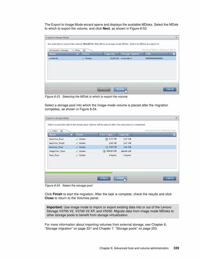
The Export to Image Mode wizard opens and displays the available MDisks. Select the MDisk to which to export the volume, and click Next, as shown in Figure 8-53.
Figure 8-53 Selecting the MDisk to which to export the volume
Select a storage pool into which the image-mode volume is placed after the migration completes, as shown in Figure 8-54.
Figure 8-54 Select the storage pool
Click Finish to start the migration. After the task is complete, check the results and click Close to return to the Volumes panel.
For more information about importing volumes from external storage, see Chapter 6, “Storage migration” on page 221 and Chapter 7, “Storage pools” on page 253.
Important: Use image mode to import or export existing data into or out of the Lenovo Storage V3700 V2, V3700 V2 XP, and V5030. Migrate data from image mode MDisks to other storage pools to benefit from storage virtualization.
Chapter 8. Advanced host and volume administration 339

8.4.10 Deleting a volume
To delete a volume, select Delete from the Actions menu. Confirm the number of volumes and select the check box if you want to force the deletion. Figure 8-55 shows the Delete Volume panel.
Figure 8-55 Delete Volume panel
Click Delete to remove the selected volume or volumes from the system. After the task completes, click Close to return to the Volumes panel.
8.4.11 Duplicating a volume
You can create a new volume by using the same presets and parameters as an existing volume. These parameters are shown:
� Volume preset (generic, thin-provision, and compressed)� Volume size� Storage pool� Access and caching I/O group� Caching mode� Easy Tier status� Virtualization type
Important: You must force the deletion if the volume has host mappings or if the volume is used in FlashCopy mappings. To be cautious, always ensure that the volume has no association before you delete it.
Important: Duplicating a volume does not duplicate the volume data. The duplicating task creates a volume with the same preset and volume parameters as the source volume. Duplicating mirrored and image-mode volumes is not supported.
340 Implementing the Lenovo Storage V3700 V2 and V5030 Systems

To duplicate a volume, select Duplicate from the Actions menu (Figure 8-56).
Figure 8-56 Duplicate volume option
The Duplicate Volume window, which is shown in Figure 8-57, can be used to change the name of the new volume. By default, a sequence integer is appended to the name of the volume to be duplicated.
Figure 8-57 Duplicate Volume
Click Duplicate to start the process. If the task completion dialog stays on the window, review the process results and click Close.
Chapter 8. Advanced host and volume administration 341

8.4.12 Adding a volume copy
If a volume consists of only one copy, you can add a second mirrored copy of the volume. This second copy can be generic or thin-provisioned.
You can also use this method to migrate data across storage pools with different extent sizes.
To add a second copy, select the volume and click Actions → Add Volume Copy, as shown in Figure 8-58.
Figure 8-58 Add Volume Copy option
342 Implementing the Lenovo Storage V3700 V2 and V5030 Systems

Select the storage pool in which to create the copy. Click Add, as shown in Figure 8-59.
Figure 8-59 Add Volume Copy: Select a storage pool
The copy is created after you click Add and data starts to synchronize as a background task. If the task completion dialog stays on the window, review the results and click Close.
Now, the volume that is named volume_3 has two volume copies, which are stored in two separate storage pools (Figure 8-60).
Figure 8-60 Volume copies
Chapter 8. Advanced host and volume administration 343

8.5 Volume properties and volume copy properties
This section provides an overview of all available information that relates to the Lenovo Storage V3700 V2, V3700 V2 XP and V5030 volumes.
To open the advanced view of a volume, select Properties from the Actions menu. Click View more details to show the full list of volume properties, as shown in Figure 8-61.
Figure 8-61 Volume details overview
The following details are available:
� Name: Shows the name of the volume.
� Pool: Gives you information about the storage pool in which the volume exists. The value “many” indicates that the volume has multiple copies, which can be in different pools.
� State: Gives status information about the volume, which can be online, offline, or degraded.
� Capacity: Shows the capacity of the volume. If the volume is thin-provisioned, this number is the virtual capacity.
� UID: The volume unique identifier.
� Number of FlashCopy mappings: The number of existing FlashCopy relationships. For more information, see Chapter 10, “Copy services” on page 393.
� Caching I/O group: Specifies the volume caching I/O group.
344 Implementing the Lenovo Storage V3700 V2 and V5030 Systems

� Accessible I/O groups: Shows the I/O group that the host can use to access the volume.
� Preferred node: Specifies the ID of the preferred node for the volume.
� Encrypted: Shows whether the volume is encrypted.
� I/O throttling: You can set a maximum rate at which the volume processes I/O requests. The limit can be set in I/Os to megabytes per second (MBps). This feature is an advanced feature. You can enable this feature only by using the command-line interface (CLI), as described in Appendix A, “CLI setup and SAN Boot” on page 707.
� Mirror sync rate: After creation, or if a volume copy is offline, the mirror sync rate weights the synchronization process. Volumes with a high sync rate (100%) complete the synchronization faster than volumes with a lower priority. By default, the rate is set to 50% for all volumes.
� Cache mode: Shows whether the cache is enabled or disabled for this volume.
� Cache state: Indicates whether open I/O requests are in the cache that is not destaged to the disks.
� ID: Shows the identifier (ID) of the volume.
� UDID (OpenVMS): The unit device identifiers (UDIDs) are used by OpenVMS hosts to access the volume.
� Virtualization type: Specifies the virtualization type of the volume. The value can be striped, seq, image, or many. The value “many” indicates that the volume has multiple copies, which can have different virtualization types.
To open the advanced view of a volume copy, select the copy of the volume that you want and click Actions → Properties, as shown in Figure 8-62.
Figure 8-62 Volume copy properties
Chapter 8. Advanced host and volume administration 345

The Properties panel opens. Click View more details to show the full list of the volume copy properties, which is shown in Figure 8-63.
Figure 8-63 Volume copy properties
The following additional volume copy details are available:
� Capacity: Shows the allocated (used) and the virtual (real) capacity. You can hover your mouse pointer over the pie chart to display information for additional tiers.
� Capacity savings: Shows the method of capacity savings for the volume copy. It can be None for a generic copy, Compressed, or Thin-provisioned.
� Easy Tier: Indicates the Easy Tier state.
Mirror synchronization rate: Setting the Mirror Sync Rate to 0% disables synchronization.
346 Implementing the Lenovo Storage V3700 V2 and V5030 Systems

To change the volume copy properties, select a volume copy from the Volumes panel, and click Actions → Modify Properties. Use the Modify Properties dialog, which is shown in Figure 8-64, to customize the thin-provisioning values: Warning Threshold and Enable Autoexpand.
Figure 8-64 Modify volume copy properties
Modify the values if needed and click OK. After the task completes, check the results of the operation and click Close to return to the Volumes panel.
8.6 Advanced volume copy functions
In 8.4.1, “Advanced volume functions” on page 329, we described all of the available actions at a volume level and how to create a second volume copy. In this section, we focus on volumes that consist of two volume copies and how to apply the concept of two copies for business continuity and data migration.
Expand a volume. Then, select a copy. Open the Actions menu to display the following volume copy actions (Figure 8-65).
Figure 8-65 Volume Copy Actions menu
The following functions are available on the Actions menu:
� Create a volume from this copy� Split into a new volume (8.6.2, “Splitting into a new volume” on page 349)� Make primary (8.6.1, “Volume copy: Make Primary” on page 348)� Validate volume copies (8.6.3, “Validate Volume Copies option” on page 350)� Delete (8.6.4, “Delete volume copy option” on page 353)� Modify properties (8.5, “Volume properties and volume copy properties” on page 344)� Properties (8.5, “Volume properties and volume copy properties” on page 344)
Chapter 8. Advanced host and volume administration 347

8.6.1 Volume copy: Make Primary
When you look at the volume copies, you can see that one of the copies shows an asterisk (*) next to its name, as shown in Figure 8-66.
Figure 8-66 Volume copy names
Each volume has a primary and a secondary copy, and the asterisk indicates the primary copy. The two copies are always synchronized, which means that all writes are destaged to both copies, but all reads are always performed from the primary copy. The maximum configurable number of copies per volume is two. The roles of the copies can be changed.
To accomplish this task, select the secondary copy. Then, click Actions → Make Primary. Usually, it is a preferred practice to place the volume copies on storage pools with similar performance because the write performance is constrained if one copy is placed on a lower-performance pool.
Figure 8-67 shows the secondary copy Actions menu.
Figure 8-67 Make primary option
If you require high read performance, you can place the primary copy in a solid-state drive (SSD) pool or an externally virtualized Flash System and then place the secondary copy in a normal disk storage pool. This action maximizes the read performance of the volume and guarantees that a synchronized second copy is in your less expensive disk pool. You can migrate online copies between storage pools. For more information about how to select the copy that you want to migrate, see 8.4.8, “Migrating a volume to another storage pool” on page 335.
Click Make Primary and the role of the Copy 1 is changed to Primary, as shown in Figure 8-68.
Figure 8-68 Change the primary volume copy
If the task completion dialog stays on the window, check the process output and click Close.
348 Implementing the Lenovo Storage V3700 V2 and V5030 Systems

The volume copy feature is also a powerful option for migrating volumes, as described in 8.6.5, “Migrating volumes by using the volume copy features” on page 354.
8.6.2 Splitting into a new volume
If the two-volume copies are synchronized, you can split one of the copies to a new volume and map this volume to another host. From a storage point of view, this procedure can be performed online, which means that you can split one copy from the volume and create a copy from the remaining volume without affecting the host. However, if you want to use the split copy for testing or backup, you must ensure that the data inside the volume is consistent. Therefore, the data must be flushed to storage to make the copies consistent.
For more information about flushing the data, see your operating system documentation. The easiest way to flush the data is to shut down the hosts or application before a copy is split.
In our example, volume Win2012_Vol_03 has two copies: Copy 0 is primary and Copy 1 is secondary. To split a copy, click Split into New Volume (Figure 8-69) on any copy and the remaining secondary copy automatically becomes the primary for the source volume.
Figure 8-69 Split into New Volume option
Figure 8-70 shows the Split Volume Copy panel to specify a name for the new volume.
Figure 8-70 Split Volume Copy panel
If the task completion dialog stays on the window after the task completes, review the results and click Close to return to the Volumes panel.
Chapter 8. Advanced host and volume administration 349

As shown in Figure 8-71, the copy appears as a new volume that is named vdisk0 (unless a name was specified). The new volume can be mapped to a host.
Figure 8-71 Volumes: New volume from the split copy operation
8.6.3 Validate Volume Copies option
You can check whether the volume copies are identical and process the differences between them if they are not.
To validate the copies of a mirrored volume, complete the following steps:
1. From the Actions menu, select Validate Volume Copies, as shown in Figure 8-72.
Figure 8-72 Actions menu: Validate Volume Copies
Important: If you receive error message code CMMVC6357E while you are splitting a volume copy, click the Running Tasks icon to view the synchronization status. Then, wait for the copy to synchronize and repeat the splitting process.
350 Implementing the Lenovo Storage V3700 V2 and V5030 Systems

2. The Validate Volume Copies dialog opens, as shown in Figure 8-73.
Figure 8-73 Validate Volume Copies panel
The following options are available:
– Generate Event of Differences
Use this option if you want to verify that the mirrored volume copies are identical. If any difference is identified, the command stops and logs an error that includes the logical block address (LBA) and the length of the first difference. You can use this option, starting at a different LBA each time, to count the number of differences on a volume.
– Overwrite Differences
Use this option to overwrite contents from the primary volume copy to the other volume copy. The command corrects any differing sectors by copying the sectors from the primary copy to the copies, which are compared. Upon completion, the command process logs an event, which indicates the number of differences that were corrected. Use this option if you are sure that the primary volume copy data is correct or that your host applications can handle incorrect data.
– Return Media Error to Host
Use this option to convert sectors on all volume copies, which contain different contents, into virtual medium errors. Upon completion, the command logs an event, which indicates the number of differences that were found, the number that were converted into medium errors, and the number that were not converted. Use this option if you are unsure what the correct data is and you do not want an incorrect version of the data to be used.
3. Select which action to perform and click Validate to start the task.
4. The volume is now checked. If the task dialog stays open, review the task results and click Close.
Chapter 8. Advanced host and volume administration 351

5. Figure 8-74 shows the output when you select the volume copy Generate Event of Differences option.
Figure 8-74 Volume copy validation output
The validation process runs as a background process and might take time, depending on the volume size. You can check the status in the Running Tasks window, as shown in Figure 8-75.
Figure 8-75 Validate Volume Copies: Running Tasks
352 Implementing the Lenovo Storage V3700 V2 and V5030 Systems

8.6.4 Delete volume copy option
Click Delete (as shown in Figure 8-76) to delete a volume copy.
Figure 8-76 Actions menu: Delete a volume copy
Confirm the deletion process by clicking Yes. Figure 8-77 shows the copy deletion warning panel.
Figure 8-77 Delete a copy confirmation
If the task completion dialog is still open after the copy is deleted, review the results of the operation and click Close to return to the Volumes panel.
The copy is deleted, but the volume stays online by using the remaining copy (Figure 8-78).
Figure 8-78 Volume remains online after the copy deletion
Chapter 8. Advanced host and volume administration 353

8.6.5 Migrating volumes by using the volume copy features
In the previous sections, we showed how to create, synchronize, split, and delete volume copies. A combination of these tasks can be used to migrate volumes to other storage pools.
The easiest way to migrate volume copies is to use the migration feature that is described in 8.4.8, “Migrating a volume to another storage pool” on page 335. By using this feature, one extent after another is migrated to the new storage pool. However, the use of volume copies provides another way to migrate volumes if the storage pool extent sizes differ.
To migrate a volume, complete the following steps:
1. Create a second copy of your volume in the target storage pool. For more information, see 8.4.12, “Adding a volume copy” on page 342.
2. Wait until the copies are synchronized.
3. Change the role of the copies and make the new copy the primary copy. For more information, see 8.6, “Advanced volume copy functions” on page 347.
4. Split or delete the old copy from the volume. For more information, see 8.6.2, “Splitting into a new volume” on page 349 or 8.6.4, “Delete volume copy option” on page 353.
This migration process requires more user interaction with the Lenovo Storage V3700 V2, V3700 V2 XP, and V5030 GUI, but it offers benefits. For example, we look at migrating a volume from a tier 1 storage pool to a lower-performance tier 2 storage pool.
In step 1, you create the copy on the tier 2 pool, while all reads are still performed in the tier 1 pool to the primary copy. After the synchronization, all writes are destaged to both pools, but the reads are still only from the primary copy.
Because the copies are fully synchronized, you can switch their roles online (step 3), and analyze the performance of the new pool. After you test your lower performance pool, you can split or delete the old copy in tier 1 or switch back to tier 1 in seconds if the tier 2 storage pool did not meet your requirements.
354 Implementing the Lenovo Storage V3700 V2 and V5030 Systems

8.7 Volumes by storage pool
To see the layout of volumes within pools, click Volumes by Pool, as shown in Figure 8-79.
Figure 8-79 Volumes by Pool menu
The Volumes by Pool panel opens, as shown in Figure 8-80.
Figure 8-80 Volumes by Pool panel
The left pane is called the pool filter. The storage pools are displayed in the pool filter. For more information about storage pools, see Chapter 7, “Storage pools” on page 253.
In the upper right, you see information about the pool that you selected in the pool filter. The following information is also shown:
� Pool icon: Because storage pools can have different characteristics, you can change the storage pool icon by clicking it. For more information, see 7.3, “Working with storage pools” on page 293.
� Pool name: The name that was entered when the storage pool was created. Click it to change the name, if needed.
Chapter 8. Advanced host and volume administration 355

� Pool details: Shows you the information about the storage pools, such as the status, number of managed disks, and Easy Tier status.
� Volume allocation: Shows you the amount of capacity that is allocated to volumes from this storage pool.
The lower-right section lists all volumes with at least one copy in the selected storage pool. The following information is provided:
� Name: Shows the name of the volume.� State: Shows the status of the volume.� UID: Shows the volume unique identifier (UID).� Host mappings: Shows whether host mappings exist.� Capacity: Shows the capacity that is presented to hosts.
Also, you can create volumes from this panel. Click Create Volumes to open the Volume Creation panel. The steps are described in Chapter 5, “Volume configuration” on page 189.
Selecting a volume and opening the Actions menu or right-clicking the volume shows the same options as described in 8.4, “Advanced volume administration” on page 328.
8.8 Volumes by host
To see an overview of the volumes that a host can access, click Volumes by Host, as shown in Figure 8-81.
Figure 8-81 Volumes by Host option
356 Implementing the Lenovo Storage V3700 V2 and V5030 Systems

The Volumes by Host panel opens, as shown in Figure 8-82.
Figure 8-82 Volumes by Host panel
The host filter is in the left pane of the view. Selecting a host shows its properties in the right pane, such as the host name, number of ports, host type, and the I/O group to which it has access.
The host icons show an orange cable for a Fibre Channel host, a black cable for a SAS host, and a blue cable for an iSCSI host.
The volumes that are mapped to this host are listed in the table in lower-right part of the panel.
You can create a volume from this panel. Click Create Volumes to open the same wizard as described in Chapter 5, “Volume configuration” on page 189.
Selecting a volume and opening the Actions menu or right-clicking the volume shows the same options as described in 8.4, “Advanced volume administration” on page 328.
Chapter 8. Advanced host and volume administration 357

358 Implementing the Lenovo Storage V3700 V2 and V5030 Systems

Chapter 9. Easy Tier
In today’s storage industry, flash drives are emerging as an attractive alternative to hard disk drives (HDDs). Because of their low response times, high throughput, and I/O per second (IOPS) energy-efficient characteristics, flash drives can help your storage infrastructure achieve significant savings in operational costs. However, the current acquisition cost per GB for flash is higher than for Enterprise serial-attached Small Computer System Interface (SCSI) (SAS) and Nearline (NL) SAS.
Enterprise SAS drives replaced the old SCSI drives. They are common in the storage market. They are offered in various capacities, spindle speeds, and form factors. Nearline SAS is the low-cost, large-capacity storage drive class, which is commonly offered at 7200 rpm spindle speed.
It is critical to choose the correct mix of drives and the correct data placement to achieve optimal performance at low cost. Maximum value can be derived by placing “hot” data with high I/O density and low response time requirements on Flash. Enterprise class disks are targeted for “warm” and Nearline for “cold” data that is accessed sequentially and at lower rates.
This chapter describes the Easy Tier disk performance optimization function of the Lenovo Storage V3700 V2, V3700 V2 XP, and V5030. It also describes how to activate the Easy Tier process for both evaluation purposes and for automatic extent migration.
This chapter includes the following topics:
� 9.1, “Generations of Easy Tier” on page 360� 9.2, “New features in Easy Tier 3” on page 360� 9.3, “Easy Tier overview” on page 361� 9.4, “Easy Tier process” on page 365� 9.5, “Easy Tier configuration by using the GUI” on page 371� 9.6, “Easy Tier configuration by using the command-line interface” on page 381� 9.7, “IBM Storage Tier Advisor Tool” on page 388
9
© Copyright Lenovo 2018. All rights reserved. 359

9.1 Generations of Easy Tier
The first generation of Easy Tier introduced automated storage performance management, efficiently boosting enterprise-class performance with flash drives and automating storage tiering from enterprise-class drives to flash drives. It also introduced dynamic volume relocation and dynamic extent pool merge.
The second generation of Easy Tier introduced the combination of nearline drives with the objective of maintaining optimal performance at low cost.
The third generation of Easy Tier introduces further enhancements that provide automated storage performance and storage economics management across all three drive tiers (Flash, Enterprise, and Nearline storage tiers). You can consolidate and efficiently manage more workloads on a single Lenovo Storage V3700 V2, V3700 V2 XP, and V5030. The third generation of Easy Tier introduces support for storage pool balancing in homogeneous pools.
9.2 New features in Easy Tier 3
The enhancements of Easy Tier 3 are shown:
� Support for three tiers of disk or a mixture of any two tiers� Storage pool balancing� Enhancements to the Storage Tier Automation Tool, including additional graphing from the
STAT Utility
Figure 9-1 shows the supported Easy Tier pools that are available in the third generation of Easy Tier.
Figure 9-1 Supported Easy Tier pools
360 Implementing the Lenovo Storage V3700 V2 and V5030 Systems

9.3 Easy Tier overview
Easy Tier is an optional licensed function of the Lenovo Storage V3700 V2, V3700 V2 XP, and V5030 that brings enterprise storage enhancements to the entry and midrange segment. It enables automated subvolume data placement throughout different storage tiers to intelligently align the system with current workload requirements and to optimize the usage of storage. This function includes the ability to automatically and nondisruptively relocate data (at the extent level) from one tier to another tier in either direction to achieve the best available storage performance for your workload in your environment.
Easy Tier reduces the I/O latency for hot spots, but it does not replace storage cache. Easy Tier and storage cache solve a similar access latency workload problem, but these methods weigh differently in the algorithmic construction based on “locality of reference,” recency, and frequency. Because Easy Tier monitors I/O performance from the extent end (after cache), it can pick up the performance issues that cache cannot solve and complement the overall storage system performance.
In general, the storage environment I/O is monitored on volumes, and the entire volume is always placed inside one appropriate storage tier. Determining the amount of I/O on single extents is too complex for monitoring I/O statistics, moving them manually to an appropriate storage tier, and reacting to workload changes.
Easy Tier is a performance optimization function that overcomes this issue because it automatically migrates (or moves) extents that belong to a volume between different storage tiers, as shown in Figure 9-2. Because this migration works at the extent level, it is often referred to as sublogical unit number (LUN) migration.
Figure 9-2 Easy Tier
You can enable Easy Tier for storage on a volume basis. It monitors the I/O activity and latency of the extents on all volumes that are enabled for Easy Tier over a 24-hour period. Based on the performance log, it creates an extent migration plan and dynamically moves high activity or hot extents to a higher disk tier within the same storage pool. It also moves extents whose activity dropped off (or cooled) from higher disk tier managed disks (MDisks) back to a lower tier MDisk.
Chapter 9. Easy Tier 361

To enable this migration between MDisks with different tier levels, the target storage pool must consist of MDisks with different characteristics. These pools are named multi-tiered storage pools. Lenovo Storage V3700 V2, V3700 V2 XP, and V5030 Easy Tier is optimized to boost the performance of storage pools that contain Flash, Enterprise, and the Nearline drives.
To identify the potential benefits of Easy Tier in your environment before you install higher MDisk tiers (such as Flash), you can enable the Easy Tier monitoring on volumes in single-tiered storage pools. Although the Easy Tier extent migration is not possible within a single-tiered pool, the Easy Tier statistical measurement function is possible. Enabling Easy Tier on a single-tiered storage pool starts the monitoring process and logs the activity of the volume extents.
IBM Storage Tier Advisor Tool (STAT) is a no-cost tool that helps you analyze this data. If you do not have an Lenovo Storage V3700 V2, V3700 V2 XP, and V5030, use Disk Magic to get a better idea about the required number of different drive types that are appropriate for your workload.
Easy Tier is available for the Lenovo Storage V3700 V2, V3700 V2 XP, and V5030 internal volumes and volumes on external virtualized storage subsystems (Lenovo Storage V5030 only).
9.3.1 Tiered storage pools
With the Lenovo Storage V3700 V2, V3700 V2 XP, and V5030, we must differentiate between the following types of storage pools:
� Single-tiered storage pools� Multi-tiered storage pools
362 Implementing the Lenovo Storage V3700 V2 and V5030 Systems

Figure 9-3 shows single-tiered storage pools that include one type of disk tier attribute. Each disk, ideally, has the same size and performance characteristics. Multi-tiered storage pools are populated with two or more different disk tier attributes, high-performance flash drives, enterprise SAS drives, and Nearline drives.
A volume migration occurs when the complete volume is migrated from one storage pool to another storage pool. An Easy Tier data migration moves only extents inside the storage pool to different performance attributes.
Figure 9-3 Tiered storage pools
By default, Easy Tier is enabled on any pool that contains two or more classes of disk drive. The Easy Tier function manages the extent migration:
� Promote
Moves the candidate hot extent to a higher performance tier.
� Warm demote:
– Prevents performance overload of a tier by demoting a warm extent to a lower tier.– Triggered when bandwidth or I/O per second (IOPS) exceeds a predefined threshold.
� Cold demote
Coldest extent moves to a lower tier.
Chapter 9. Easy Tier 363

� Expanded or cold demote
Demote appropriate sequential workload to the lowest tier to better use nearline bandwidth.
� Swap
This operation exchanges a cold extent in a higher tier with a hot extent in a lower tier or vice versa.
Figure 9-4 shows the Easy Tier extent migration.
Figure 9-4 Easy Tier process
Note: Extent migrations occur only between adjacent tiers.
364 Implementing the Lenovo Storage V3700 V2 and V5030 Systems

9.4 Easy Tier process
Easy Tier is based on an algorithm with a threshold to evaluate if an extent is cold, warm, or hot. Easy Tier consists of four main processes. These processes ensure that the extent allocation in multi-tiered storage pools is optimized for the best performance, based on your workload in the last 24 hours. The processes are listed:
� I/O Monitoring� Data Placement Advisor� Data Migration Planner� Data Migrator
Figure 9-5 shows the flow between these processes.
Figure 9-5 Easy Tier process flow
The four main processes and the flow between them are described in the following sections.
9.4.1 I/O Monitoring
The I/O Monitoring (IOM) process operates continuously and monitors host volumes for I/O activity. It collects performance statistics for each extent at 5-minute intervals and derives averages for a rolling 24-hour period of I/O activity.
Easy Tier makes allowances for large block I/Os and considers only I/Os up to 64 KB as migration candidates.
IOM is an efficient process and adds negligible processing impact to the Lenovo Storage V3700 V2, V3700 V2 XP, and V5030 node canisters.
9.4.2 Data Placement Advisor
The Data Placement Advisor (DPA) uses workload statistics to make a cost benefit decision about the extents that need to be candidates for migration to a higher-performance tier.
This process also identifies extents that must be migrated back to a lower tier.
9.4.3 Data Migration Planner
By using the previously identified extents, the Data Migration Planner (DMP) process builds the extent migration plan for the storage pool.
9.4.4 Data Migrator
The Data Migrator (DM) process involves scheduling and the actual movement, or migration, of the volume’s extents up to, or down from, the high disk tier.
Chapter 9. Easy Tier 365

The extent migration rate is described.
Before firmware version 7.3, Easy Tier moved extents at a rate of approximately 12 GB every 5 minutes as a maximum speed:
� This speed is applied to all functions except cold demotes.� Extent cold demotes were limited to approximately 1 GB every 10 minutes.
With firmware version 7.3, the algorithm changed to 12 extents every 5 minutes, which caused the Easy Tier migration speed of extents with a size of less than 1 GB to be less than optimal.
With firmware version 7.5, the algorithm was changed back to the former speed:
� Also changed in 7.3.0.9 and later� Also changed in 7.4.0.3 and later
This rate equates to around 3 TB a day that is migrated between disk tiers (Figure 9-6).
Figure 9-6 Easy Tier Data Migrator
9.4.5 Easy Tier accelerated mode
Under normal production conditions, Easy Tier works well to process day-to-day workloads.
Easy Tier considers migration scenarios and scenarios where large amounts of data need to be rebalanced in its internal algorithms.
366 Implementing the Lenovo Storage V3700 V2 and V5030 Systems

Easy Tier accelerated mode was introduced in firmware version 7.5. Easy Tier accelerated mode allows the system to cope with migration situations where the user needs to speed up the Easy Tier function temporarily.
Normal Easy Tier migration speed is 12 GB every 5 minutes for all functions, except cold demote, which is 1 GB every 10 minutes.
Accelerated mode allows an Easy Tier migration speed of 48 GB every 5 minutes with no limit on cold demotes and no support for warm demotes.
You enable Easy Tier accelerated mode from the command line by using chsystem -easytieracceleration on/off.
9.4.6 Easy Tier operating modes
The Lenovo Storage V3700 V2, V3700 V2 XP, and V5030 offer the following operating modes for Easy Tier:
� Easy Tier: Off
Easy Tier can be turned off. No statistics are recorded, and no extents are moved.
� Easy Tier: On
When the Easy Tier function is turned on, Easy Tier measures the I/O activity for all extents. With a multi-tiered pool, the extents are migrated dynamically by the Easy Tier processes to achieve the best performance. The movement is transparent to the host server and applications.
A statistic summary file is created. This file can be offloaded and analyzed with the IBM Storage Tier Advisory Tool, as described in 9.7, “IBM Storage Tier Advisor Tool” on page 388. Easy Tier can be turned on for any single-tiered or multi-tiered pool.
� Easy Tier: Measured mode
When Easy Tier is in measured mode, Easy Tier measures the I/O activity for all extents but it does not move any extents in the storage pool. A statistics summary file is created. This file can be offloaded from the Lenovo Storage V3700 V2, V3700 V2 XP, and V5030. This file can be analyzed with the IBM Storage Tier Advisory Tool. This analysis shows the benefits to your workload if you add or remove different drive classes to your pool before any hardware is acquired. No license is required to set Easy Tier to measured mode.
� Easy Tier: Auto
Auto mode is the operating mode default. If Easy Tier is set to auto for a single-tiered storage pool, Easy Tier is set to off for all volumes inside the storage pool and no extents are moved. If Easy Tier is set to auto for a multi-tiered storage pool, the Easy Tier status becomes active and Easy Tier is set to on for all volumes inside the storage pool and the extents are migrated dynamically by the Easy Tier process. This scenario is similar to setting Easy Tier to on. However, the extents are not migrated if the Easy Tier function is not licensed.
Note: Accelerated mode is not intended for day-to-day Easy Tier traffic. Turn on accelerated mode when necessary. Because Easy Tier accelerated mode can increase the workload on the system temporarily, use Easy Tier accelerated mode during periods of lower system activity.
Chapter 9. Easy Tier 367

9.4.7 Easy Tier status
Depending on the Easy Tier mode attributes, the storage pool Easy Tier status can be one of the following values:
� Active: This status indicates that Easy Tier is actively managing the extents of the storage pool.
� Balanced: This status applies to homogeneous storage pools and indicates that Easy Tier is actively managing the extents to provide enhanced performance by rebalancing the extents among the MDisks within the tier. This rebalancing characteristic is called Storage Pool Balancing, which is described in 9.4.8, “Storage Pool Balancing” on page 368.
� Measured: This status means that Easy Tier is constantly measuring the I/O activity for all extents to generate an I/O statistics report.
� Inactive: When the Easy Tier status is inactive, no extents are monitored and no statistics are recorded.
9.4.8 Storage Pool Balancing
Storage Pool Balancing is a new function in firmware version 7.4 and higher, which, while it is associated with Easy Tier, operates independently and does not require a license. Storage Pool Balancing works with Easy Tier when multiple tiers exist in a single pool.
It assesses the extents in a storage tier and balances them automatically across all MDisks within that tier. Storage Pool Balancing moves the extents to achieve a balanced workload distribution and avoid hotspots. Storage Pool Balancing is an algorithm that is based on MDisk IOPS usage, which means that it is not capacity-based but performance-based. It works on a 6-hour performance window.
When a new MDisk is added to an existing storage pool, Storage Pool Balancing can automatically balance the extents across all MDisks in the pool, if required.
Figure 9-7 represents an example of Storage Pool Balancing.
Figure 9-7 Storage Pool Balancing
368 Implementing the Lenovo Storage V3700 V2 and V5030 Systems

9.4.9 Easy Tier rules
The following operating rules apply when IBM System Storage Easy Tier is used on the Lenovo Storage V3700 V2, V3700 V2 XP, and V5030:
� Automatic data placement and extent I/O activity monitors are supported on each copy of a mirrored volume. Easy Tier works with each copy independently of each other.
� Easy Tier works with all striped volumes, including these types of volumes:
– Generic volumes– Thin-provisioned volumes– Mirrored volumes– Thin-mirrored volumes– Global and Metro Mirror sources and targets
� Easy Tier automatic data placement is not supported for image mode or sequential volumes. I/O monitoring for these volumes is supported, but you cannot migrate extents on these volumes unless you convert image or sequential volume copies to striped volumes.
� The Lenovo Storage V3700 V2, V3700 V2 XP, and V5030 create volumes or volume expansions by using extents from MDisks from the Enterprise and Nearline tier. Extents from MDisks in the Flash tier are used if Enterprise space and Nearline space are not available.
� When a volume is migrated out of a storage pool that is managed with Easy Tier, Automatic Data Placement Mode is no longer active on that volume. Automatic Data Placement is also turned off while a volume is migrated, even if it is between pools that both have Easy Tier Automatic Data Placement enabled. Automatic Data Placement for the volume is re-enabled when the migration is complete.
� Flash drive performance depends on block size. (Small blocks perform better than large blocks.) Easy Tier measures I/O blocks that are smaller than 64 KB, but it migrates the entire extent to the appropriate disk tier.
� As extents are migrated, the use of smaller extents makes Easy Tier more efficient.
� The first migration starts about 1 hour after Automatic Data Placement Mode is enabled. It takes up to 24 hours to achieve optimal performance.
� In the current Lenovo Storage V3700 V2, V3700 V2 XP, and V5030 Easy Tier implementation, it takes about two days before hotspots are considered moved from tier to tier, which prevents hotspots from being moved from a fast tier if the workload changes over a weekend.
� If you run an unusual workload over a longer period, Automatic Data Placement can be turned off and turned on online to avoid data movement.
Volume mirroring: Volume mirroring can have different workload characteristics for each copy of the data because reads are normally directed to the primary copy and writes occur to both copies. Therefore, the number of extents that Easy Tier migrates probably differs for each copy.
Chapter 9. Easy Tier 369

Depending on which storage pool and which Easy Tier configuration is set, a volume copy can have the Easy Tier states that are shown in Table 9-1.
Table 9-1 Easy Tier states
Storage pool Single-tiered or multi-tiered storage pool
Volume copy Easy Tier setting
Easy Tier status on volume copy
Off Single-tiered Off Inactive
Off Single-tiered On Inactive
Off Multi-tiered Off Inactive
Off Multi-tiered On Inactive
Autoa
a. The default Easy Tier setting for a storage pool is Auto, and the default Easy Tier setting for a volume copy is On. This scenario means that Easy Tier functions are disabled for storage pools with a single tier and only Storage Pool Balancing is active.
Single-tiered Off Measuredb
Autoa Single-tiered On Balanced (see footnote e)
Autoa Multi-tiered Off Measuredb
b. When the volume copy status is measured, the Easy Tier function collects usage statistics for the volume, but automatic data placement is not active.
Autoa Multi-tiered On Activec d
c. If the volume copy is in image or sequential mode or is being migrated, the volume copy Easy Tier status is measured instead of active.
d. When the volume copy status is active, the Easy Tier function operates in automatic data placement mode for that volume.
e. When the volume Easy Tier status is balanced, Easy Tier is actively managing the extents by rebalancing them among the MDisks within the tier.
On Single-tiered Off Measuredb
On Single-tiered On Balanced (see footnote e)
On Multi-tiered Off Measuredb
On Multi-tiered On Activec
Measure Single-tiered On Measuredb
Measure Single-tiered Off Measuredb
Measure Multi-tiered On Measuredb
Measure Multi-tiered Off Measuredb
370 Implementing the Lenovo Storage V3700 V2 and V5030 Systems

9.5 Easy Tier configuration by using the GUI
This section describes how to activate Easy Tier by using the Lenovo Storage V3700 V2, V3700 V2 XP, and V5030 graphical user interface (GUI).
9.5.1 Creating multi-tiered pools: Enabling Easy Tier
In this section, we describe how to create multi-tiered storage pools by using the GUI.
When a storage pool changes from single-tiered to multi-tiered, Easy Tier is enabled by default for the pool and on all volume copies inside this pool. The current release of Easy Tier supports up to three tiers of storage (Flash, Enterprise, and Nearline).
In this example, we create a pool that contains Flash and Enterprise MDisks.
To create a multi-tiered pool, complete the following steps:
1. Click Pools → Pools. Click + Create to add a pool. Figure 9-8 shows a list of the pools in the Lenovo Storage V3700 V2, V3700 V2 XP, and V5030
Figure 9-8 Creating an Easy Tier pool
Chapter 9. Easy Tier 371

2. Provide a name for the new pool and click Create. Click Advanced if you want to use encryption. Select Enable to enable encryption on the pool, if required, as shown in Figure 9-9.
Figure 9-9 Creating an Easy Tier pool
372 Implementing the Lenovo Storage V3700 V2 and V5030 Systems

3. After you create the pool, the new pool shows in the Pools list. To show the pool properties, select the pool and select Properties from the Actions menu. No storage is assigned to the pool. The Easy Tier status is Balanced. See 9.4.7, “Easy Tier status” on page 368. The Properties panel for the pool is shown in Figure 9-10.
Figure 9-10 Pool properties panel
Chapter 9. Easy Tier 373

4. To add storage to a pool, select the pool and select Add Storage from the Actions menu, as shown in Figure 9-11.
Figure 9-11 Add Storage to a pool
5. The Assign Storage to Pool panel offers two options to configure the storage for the pool: Quick Internal or Advanced Internal Custom. Figure 9-12 shows the Quick Internal panel.
Figure 9-12 Add Storage - Quick Internal panel
374 Implementing the Lenovo Storage V3700 V2 and V5030 Systems

6. Figure 9-13 shows the Advanced Internal Custom panel.
Figure 9-13 Add Storage - Advanced Internal Custom panel
The Quick Internal panel provides a recommended configuration that is based on the number and type of installed drives. You can use the Advanced Internal Custom panel to configure the specific drive types, Redundant Array of Independent Disks (RAID) levels, spares, stripe width, and array width.
For example, in the following steps, we show how to add storage by using the Advanced method. We add one type of drive class to the pool at a time. We show that when we add the second drive class, Easy Tier is automatically enabled. Our demonstration Lenovo Storage V3700 V2, V3700 V2 XP, and V5030 systems has a number of 900 GB 10k SAS drives and 200 GB solid-state drives (SSDs) drives.
Chapter 9. Easy Tier 375

7. From the Advanced Internal Custom panel, select the required drive class, RAID type, number of spares, stripe width, and array width. Click Assign to add this storage to the pool, as shown in Figure 9-14.
Figure 9-14 Adding storage to a pool
376 Implementing the Lenovo Storage V3700 V2 and V5030 Systems

8. Click Pools → Pools, and select the required pool. Select Properties from the Actions Menu. Click View more details. The Easy Tier status is Balanced. See Figure 9-15.
Figure 9-15 Pool properties
9. Repeat steps 7 and 8 to add a second drive class. See Figure 9-16.
Figure 9-16 Adding storage to a pool
Chapter 9. Easy Tier 377

10.Review the pool properties. The Easy Tier status is Active. See Figure 9-17.
Figure 9-17 Pool properties that show that Easy Tier is active
11.Click Pools → MDisks by Pools, as shown in Figure 9-18. The Easy Tier Pool storage pool contains MDisks from the two drive classes, Flash and Enterprise.
Figure 9-18 MDisks by Pools
378 Implementing the Lenovo Storage V3700 V2 and V5030 Systems

The Volumes by Pools panel, as shown in Figure 9-19, shows a volume on the multi-tiered storage pool. Details of the pool are shown, including the number of MDisks and volumes in the pool. The pool icon has a red and blue disk representation, which indicates that this pool is an Easy Tier Pool.
If the Easy Tier Status column is enabled, it shows the Easy Tier Status of each volume. Volumes inherit the Easy Tier state of their parent pool, but Easy Tier can be toggled on or toggled off at the volume level, if required. See 9.6.2, “Enabling or disabling Easy Tier on single volumes” on page 385.
Figure 9-19 Volumes by pool
If external storage is used as a drive class, you must select the drive class type manually. Then, add the external MDisks to a storage pool, as described in 11.2, “Working with external storage” on page 553. If the internal storage and the external storage are in different drive classes, this action also changes the storage pool to a multi-tiered storage pool and enables Easy Tier on the pool and associated volumes.
9.5.2 Downloading Easy Tier I/O measurements
Easy Tier is now enabled and Automatic Data Placement Mode is active. Extents are automatically migrated to or from disk tiers, and the statistics summary collection is now active. The statistics log file can be downloaded to analyze how many extents were migrated and to monitor whether it makes sense to add more Flash to the multi-tiered storage pool.
Heat data files are produced approximately once a day (that is, roughly every 24 hours) when Easy Tier is active on one or more storage pools.
Chapter 9. Easy Tier 379

To download the statistics file, complete the following steps:
1. Click Settings → Support, as shown in Figure 9-20.
Figure 9-20 Settings menu
2. Click Show full log listing, as shown in Figure 9-21.
Figure 9-21 Show full log listing
This action lists all of the log files that are available to download. The Easy Tier log files are always named dpa_heat.canister_name_date.time.data.
If you run Easy Tier for a longer period, it generates a heat file at least every 24 hours. The time and date that the file was created is included in the file name.
380 Implementing the Lenovo Storage V3700 V2 and V5030 Systems

3. To download the statistics file, select the file for the most representative period and click Actions → Download as shown in Figure 9-22. Usually, this file is the latest file.
Figure 9-22 Download the dpa_heat file
You can also use the search field to filter your search, as shown in Figure 9-23.
Figure 9-23 Filter your search
Depending on your browser settings, the file is downloaded to your default location, or you are prompted to save it to your computer. This file can be analyzed as described in 9.7, “IBM Storage Tier Advisor Tool” on page 388.
9.6 Easy Tier configuration by using the command-line interface
The process to enable Lenovo Storage V3700 V2, V3700 V2 XP, and V5030 Easy Tier by using the GUI is described in 9.5, “Easy Tier configuration by using the GUI” on page 371. Easy Tier can also be configured by using the command-line interface (CLI). For the advanced user, this method offers more options for Easy Tier configuration.
Before you use the CLI, you must configure CLI access, as described in Appendix A, “CLI setup and SAN Boot” on page 707.
Log file creation: Depending on your workload and configuration, it can take up to 24 hours until a new Easy Tier log file is created.
Chapter 9. Easy Tier 381

9.6.1 Enabling Easy Tier measured mode
You can enable Easy Tier in measured mode on either a single-tiered or multi-tiered storage pool. Connect to your Lenovo Storage V3700 V2, V3700 V2 XP, and V5030 by using the CLI and run the svcinfo lsmdiskgrp command, as shown in Example 9-1. This command shows an overview of all configured storage pools and their Easy Tier status. In our example, two storage pools are listed: Nearline_Pool with Easy Tier in auto status, and Multi_Tier_Pool with Easy Tier on.
Example 9-1 Show all configured storage pools
IBM_Storwize:ITSO_V5000:superuser>svcinfo lsmdiskgrpid name status mdisk_count easy_tier easy_tier_status type0 Nearline_Pool online 1 auto balanced parent1 EasyTier_Pool online 3 on active parentIBM_Storwize:ITSO_V5000:superuser>
For a detailed view of the single-tiered storage pool, run the svcinfo lsmdiskgrp storage pool name command, as shown in Example 9-2.
Example 9-2 Storage pool details: Easy Tier auto
IBM_Storwize:ITSO_V5000:superuser>svcinfo lsmdiskgrp Nearline_Poolid 0name Nearline_Poolstatus onlinemdisk_count 1...easy_tier autoeasy_tier_status balancedtier nearlinetier_mdisk_count 1type parent...IBM_Storwize:ITSO_V5000:superuser>
To enable Easy Tier on a single-tiered storage pool in measure mode, run the chmdiskgrp -easytier measure storage pool name command, as shown in Example 9-3.
Example 9-3 Enable Easy Tier in measure mode on a single-tiered storage pool
IBM_Storwize:ITSO_V5000:superuser>chmdiskgrp -easytier measure Nearline_PoolIBM_Storwize:ITSO_V5000:superuser>
Readability: In most of the examples that are shown in this section, we deleted many unrelated lines in the command output or responses so that you can focus on the information that relates to Easy Tier.
382 Implementing the Lenovo Storage V3700 V2 and V5030 Systems

Check the status of the storage pool again by running the lsmdiskgrp storage pool name command again, as shown in Example 9-4.
Example 9-4 Storage pool details: Easy Tier measure status
IBM_Storwize:ITSO_V5000:superuser>lsmdiskgrp Nearline_Poolid 0name Nearline_Poolstatus onlinemdisk_count 1vdisk_count 2capacity 1.81TBextent_size 1024free_capacity 1.80TBvirtual_capacity 11.00GBused_capacity 11.00GBreal_capacity 11.00GBoverallocation 0warning 90easy_tier measureeasy_tier_status measuredtier ssdtier_mdisk_count 0tier_capacity 0.00MBtier_free_capacity 0.00MBtier enterprisetier_mdisk_count 0tier_capacity 0.00MBtier_free_capacity 0.00MBtier nearlinetier_mdisk_count 1tier_capacity 1.81TBtier_free_capacity 1.80TBparent_mdisk_grp_id 2parent_mdisk_grp_name Nearline_Poolchild_mdisk_grp_count 0child_mdisk_grp_capacity 0.00MBtype parentIBM_Storwize:ITSO_V5000:superuser>
For a list of all of the defined volumes, run the lsvdisk command, as shown in Example 9-5. For this example, we are interested in the RedbookVolume volume only.
Example 9-5 All volumes list
IBM_Storwize:ITSO_V5000:superuser>lsvdiskid name IO_group_id IO_group_name status mdisk_grp_id ...26 RedbookVolume 0 io_grp0 online 0...
Chapter 9. Easy Tier 383

For a detailed view of a volume, run the lsvdisk volume_name command, as shown in Example 9-6. This output shows two copies of a volume. Easy Tier is turned on on both copies. However, Copy 0 is in a multi-tiered storage pool and Automatic Data Placement is active, as indicated by the easy_tier_status line. Copy 1 is in the single-tiered storage pool, and Easy Tier mode is measured, as indicated by the easy_tier_status line.
Example 9-6 Volume details
IBM_Storwize:ITSO_V5000:superuser>lsvdisk RedbookVolumeid 26name RedbookVolumeIO_group_id 0IO_group_name io_grp0status onlinemdisk_grp_id manymdisk_grp_name manycapacity 10.00GB......
copy_id 0status onlinesync yesprimary yesmdisk_grp_id 1mdisk_grp_name EasyTier_Pool...easy_tier oneasy_tier_status activetier ssdtier_capacity 0.00MBtier enterprisetier_capacity 10.00GBtier nearlinetier_capacity 0.00MB
...
copy_id 1status onlinesync nomdisk_grp_id 0mdisk_grp_name Nearline_Poolused_capacity 10.00GBreal_capacity 10.00GBfree_capacity 0.00MBoverallocation 100grainsizese_copy noeasy_tier offeasy_tier_status measuredtier ssdtier_capacity 0.00MBtier enterprisetier_capacity 0.00MBtier nearline
384 Implementing the Lenovo Storage V3700 V2 and V5030 Systems

tier_capacity 10.00GBparent_mdisk_grp_id 2parent_mdisk_grp_name Nearline_PoolIBM_Storwize:ITSO_V5000:superuser>
Easy Tier measured mode does not place data. Easy Tier measured mode collects statistics for measurement only. For more information about downloading and analyzing the I/O statistics, see 9.5.2, “Downloading Easy Tier I/O measurements” on page 379.
9.6.2 Enabling or disabling Easy Tier on single volumes
If you enable Easy Tier on a storage pool, Easy Tier is enabled on all volume copies inside the Easy Tier pools also, by default. This setting applies to multi-tiered and single-tiered storage pools. It is also possible to turn on and turn off Easy Tier for single volume copies.
Before you disable Easy tier on a single volume, run the svcinfo lsmdisgrp storage pool name command to list all storage pools that are configured, as shown in Example 9-7. In our example, EasyTier_Pool is the storage pool that is used as a reference.
Example 9-7 Listing the storage pool
IBM_Storwize:ITSO_V5000:superuser>svcinfo lsmdiskgrpid name status easy_tier easy_tier_status.1 EasyTier_Pool online on active ..IBM_Storwize:ITSO_V5000:superuser>
Run the svcinfo lsvdisk command to show all configured volumes within your Lenovo Storage V3700 V2, V3700 V2 XP, and V5030, as shown in Example 9-8. We are only interested in a single volume.
Example 9-8 Show all configured volumes
IBM_Storwize:ITSO_V5000:superuser>svcinfo lsvdiskid name IO_group_id status mdisk_grp_id mdisk_grp_name capacity 0 Volume001 0 online 1 EasyTier_Pool 5.00GB IBM_Storwize:ITSO_V5000:superuser>
To disable Easy Tier on single volumes, run the svctask chvdisk -easytier off volume name command, as shown in Example 9-9.
Example 9-9 Disable Easy Tier on a single volume
IBM_Storwize:ITSO_V5000:superuser>svctask chvdisk -easytier off Volume001IBM_Storwize:ITSO_V5000:superuser>
Chapter 9. Easy Tier 385

This command disables Easy Tier on all copies of the volume. Example 9-10 shows Easy Tier turned off for copy 0 even if Easy Tier is still enabled on the storage pool. The status for copy 0 changed to measured because the pool is still actively measuring the I/O on the volume.
Example 9-10 Easy Tier that is disabled
IBM_Storwize:ITSO_V5000:superuser>svcinfo lsvdisk Volume001id 0name Volume001IO_group_name io_grp0status onlinemdisk_grp_id 1mdisk_grp_name EasyTier_Poolcapacity 5.00GBtype stripedthrottling 0preferred_node_id 2parent_mdisk_grp_id 1parent_mdisk_grp_name EasyTier_Pool
copy_id 0status onlinemdisk_grp_id 1mdisk_grp_name EasyTier_Poolfast_write_state emptyused_capacity 5.00GBreal_capacity 5.00GBfree_capacity 0.00MBoverallocation 100easy_tier offeasy_tier_status measuredtier ssdtier_capacity 1.00GBtier enterprisetier_capacity 4.00GBtier nearlinetier_capacity 0.00MBcompressed_copy nouncompressed_used_capacity 5.00GBparent_mdisk_grp_id 1parent_mdisk_grp_name EasyTier_PoolIBM_Storwize:ITSO_V5000:superuser>
386 Implementing the Lenovo Storage V3700 V2 and V5030 Systems

To enable Easy Tier on a volume, run the svctask chvdisk -easytier on volume name command (as shown in Example 9-11). Easy Tier changes back to on (as shown in Example 9-12). The copy 0 status also changed back to active.
Example 9-11 Easy Tier enabled
IBM_Storwize:ITSO_V5000:superuser>svctask chvdisk -easytier on Volume001IBM_Storwize:ITSO_V5000:superuser>
Example 9-12 Easy Tier on single volume enabled
IBM_Storwize:ITSO_V5000:superuser>svcinfo lsvdisk Volume001id 0name Volume001IO_group_id 0IO_group_name io_grp0status onlinemdisk_grp_id 1mdisk_grp_name EasyTier_Poolcapacity 5.00GBparent_mdisk_grp_id 1parent_mdisk_grp_name EasyTier_Pool
copy_id 0status onlinemdisk_grp_id 1mdisk_grp_name EasyTier_Pooltype stripedmdisk_idmdisk_nameused_capacity 5.00GBreal_capacity 5.00GBfree_capacity 0.00MBoverallocation 100easy_tier oneasy_tier_status activetier ssdtier_capacity 1.00GBtier enterprisetier_capacity 4.00GBtier nearlinetier_capacity 0.00MBcompressed_copy nouncompressed_used_capacity 5.00GBparent_mdisk_grp_id 1parent_mdisk_grp_name EasyTier_PoolIBM_Storwize:ITSO_V5000:superuser>
Chapter 9. Easy Tier 387

9.7 IBM Storage Tier Advisor Tool
IBM Storage Tier Advisor Tool (STAT) is a Microsoft Windows console tool. If you run Easy Tier in measure mode, the tool analyzes the extents and captures I/O profiles to estimate how much benefit you can derive from implementing Easy Tier Automatic Data Placement with additional MDisks tiers. If Automatic Data Placement Mode is already active, the analysis also includes an overview of migrated hot data and advice about whether you can derive any benefit from adding more Flash or Enterprise drives, for example.
The output provides a graphical representation of the performance data that is collected by Easy Tier over a 24-hour operational cycle.
The tool comes packaged as an International Organization for Standardization (ISO) file, which needs to be extracted to a temporary folder. The STAT can be downloaded from the following link:
https://ibm.biz/BdEfrX
9.7.1 Processing heat log files
IBM Storage Tier Advisor Tool takes input from the dpa_heat log file and produces an HTML file that contains the report. Download the heat_log file, as described in 9.5.2, “Downloading Easy Tier I/O measurements” on page 379, and save it to the hard disk drive (HDD) of a Windows system.
For more information about the tool and to download it, see this website:
https://ibm.biz/BdEfrX
Click Start → Run, enter cmd, and then click OK to open a command prompt.
Typically, the tool is installed in the C:\Program Files\IBM\STAT directory. Enter the command to generate the report, as shown in Example 9-13:
C:\Program Files\IBM\STAT>STAT.exe -o c:\directory_where_you_want_the output_to_go c:\location_of_dpa_heat_data_file
If you do not specify -o c:\directory_where_you_want_the output_to_go, the output goes to the directory of the STAT.exe file.
Example 9-13 Generate the HTML file
C:\EasyTier>STAT.exe -o C:\EasyTier C:\StorwizeV5000_Logs\dpa_heat.31G00KV-1.101209.131801.data
CMUA00019I The STAT.exe command has completed.
C:\EasyTier>
IBM Storage Tier Advisor Tool creates a set of HTML files. Browse to the directory where you directed the output file, and locate the file that is named index.html. Open the file by using your browser to view the report.
Typically, the STAT tool generates the report that is described in 9.7.2, “Storage Tier Advisor Tool reports” on page 389.
388 Implementing the Lenovo Storage V3700 V2 and V5030 Systems

9.7.2 Storage Tier Advisor Tool reports
When you open the index.html file of an Lenovo Storage V3700 V2, V3700 V2 XP, and V5030 systems, a window opens that gives you a complete system summary report as shown in Figure 9-24.
Figure 9-24 STAT report: System Summary
As shown in Figure 9-24, the prediction that is generated by the Storage Tier Advisor Tool is pool-based. The first page of the report shows the Storage facility, total number of storage pools and volumes that are monitored, total capacity that is monitored, hot data capacity, data validity, and system state.
The next table shows how data is managed in the particular storage pool. The data management is indicated by different colors. The total capacity of the storage pool is divided into two parts: the data that is managed by Easy Tier and the unallocated space. The green portion of the bar represents the data that is managed by Easy Tier. The black portion of the bar represents the unallocated space or data that is not managed by Easy Tier.
Chapter 9. Easy Tier 389

In our example, a total of three storage pools were monitored with a total capacity of 2063.0 GiB. Click storage pool P1 as shown in Figure 9-25.
Figure 9-25 Selecting storage pool P1
As shown in Figure 9-26, IBM Storage Tier Advisor Tool shows the MDisk distribution of each tier that makes up the storage pool. The tool also shows the performance statistics and the projected IOPS for the MDisks after the Easy Tier processes and rebalancing operations are completed on the extents of the storage pool.
For each MDisk, the STAT tool shows the following values:
� MDisk ID� Storage pool ID� MDisk type� Number of IOPS threshold exceeded� Utilization of MDisk IOPS� Projected utilization of MDisk IOPS
Figure 9-26 Storage pool performance statistics
The blue portion of the bar represents the percentage that is below the tier average utilization of MDisk IOPS.
The red portion of the bar represents the percentage that is above the maximum allowed threshold.
390 Implementing the Lenovo Storage V3700 V2 and V5030 Systems

In our example, the STAT output shows 0% utilization of the Flash tier. Therefore, no extents are in this particular tier. In the Enterprise section, the STAT shows 8% utilization of the Enterprise tier and the IOPS did not exceed the threshold.
In the Nearline section, we look at 182% of utilization. Therefore, in a period of 24 hours, the maximum IOPS exceeded the threshold by 82%. The blue portion shows that 90% of 182% (approximately 49.5%) of the IOPS did not exceed the threshold for this particular tier. The red portion shows that 92% of 182% (approximately 50.5%) of the IOPS exceeded the threshold and the extents are potential candidates to move to a higher tier.
In the Workload Distribution Across Tier section, the STAT shows the skew of the workload of the storage pool that was selected. The X-axis (horizontal) shows the percentage of extents in use. The Y-axis (vertical) shows the percentage of extents that are busy of the provided percentage from the X-axis. In our graph, for instance, when we look at 10% of the extents in the pool, only about 40% of these extents are determined to be busy. Figure 9-27 shows an example of our graph.
Figure 9-27 STAT project workload distribution
In the Volume Heat Distribution section, the STAT shows volume heat distribution of all volumes in the storage pool. The columns are listed:
� Virtual disk (VDisk) ID� VDisk Copy ID� Configured size or VDisk capacity� I/O percentage of extent pool� The tiers that the volume takes capacity from � The capacity on each of the tiers� The heat distribution of that storage pool
The heat distribution of a volume is displayed by using a colored bar that represents the following information. The blue portion of the bar represents the capacity of cold extents in the volume. Extents are considered cold when the extent is not used heavily or the IOPS is low.
The orange portion of the bar represents the capacity of warm extents in the volume. Data is considered warm when it is either relatively heavy or the IOPS is relatively more compared to the cold extents or lower when compared to hot extents.
The red portion of the bar represents the capacity of hot data in the volume. Data is considered hot when it is used most heavily or the IOPS on that data was the highest.
Chapter 9. Easy Tier 391

Figure 9-28 shows a few examples of the volume heat distribution.
Figure 9-28 Volume heat distribution
The Systemwide Recommendation section can be viewed on another page, which shows the advised configuration for the tiers as applicable for the configuration of the system. Typically, it shows three recommended configurations: Flash (SSD), Enterprise, and Nearline.
Each recommendation displays the storage pools, the recommendation, and the expected improvement. An example is shown in Figure 9-29.
Figure 9-29 STAT Systemwide Recommendation section
392 Implementing the Lenovo Storage V3700 V2 and V5030 Systems

Chapter 10. Copy services
In this chapter, we describe the copy services functions that are provided by the Lenovo Storage V3700 V2, V3700 V2 XP, and V5030 storage systems, including FlashCopy and Remote Copy. Copy services functions are useful for making data copies for backup, application test, recovery, and so on. The Lenovo Storage V3700 V2, V3700 V2 XP, and V5030 systems make it easy to apply these functions to your environment through its intuitive graphical user interface (GUI).
This chapter includes the following topics:
� 10.1, “FlashCopy” on page 394� 10.2, “Remote Copy” on page 453� 10.3, “Troubleshooting Remote Copy” on page 469� 10.4, “Managing Remote Copy by using the GUI” on page 473� 10.5, “HyperSwap” on page 511
10
© Copyright Lenovo 2018. All rights reserved. 393

10.1 FlashCopy
By using the FlashCopy function of the Lenovo Storage V3700 V2, V3700 V2 XP, and V5030 systems, you can create a point-in-time copy of one or more volumes. In this section, we describe the structure of FlashCopy and provide details about its configuration and use.
You can use FlashCopy to solve critical and challenging business needs that require the duplication of data on your source volume. Volumes can remain online and active while you create consistent copies of the data sets. Because the copy is performed at the block level, it operates below the host operating system and cache and, therefore, is not apparent to the host.
While the FlashCopy operation is performed, I/O to the source volume is frozen briefly to initialize the FlashCopy bitmap and then the I/O is allowed to resume. Although several FlashCopy options require the data to be copied from the source to the target in the background (which can take time to complete), the resulting data on the target volume copy appears to complete immediately. This task is accomplished by using a bitmap (or bit array) that tracks changes to the data after the FlashCopy is started, and an indirection layer, which allows data to be read from the source volume transparently.
10.1.1 Business requirements for FlashCopy
When you are deciding whether FlashCopy addresses your needs, you must adopt a combined business and technical view of the problems that you must solve. Determine your needs from a business perspective, and then determine whether FlashCopy fulfills the technical needs of those business requirements.
With an immediately available copy of the data, FlashCopy can be used in the following business scenarios:
� Rapidly creating consistent backups of dynamically changing data
FlashCopy can be used to create backups through periodic running. The FlashCopy target volumes can be used to complete a rapid restore of individual files or the entire volume through Reverse FlashCopy (by using the -restore option).
The target volumes that are created by FlashCopy can also be used for backup to tape. By attaching them to another server and performing backups from there, it allows the production server to continue largely unaffected. After the copy to tape completes, the target volumes can be discarded or kept as a rapid restore copy of the data.
� Rapidly creating consistent copies of production data to facilitate data movement or migration between hosts
FlashCopy can be used to facilitate the movement or migration of data between hosts while you minimize the downtime for applications. FlashCopy allows application data to be copied from source volumes to new target volumes while applications remain online. After the volumes are fully copied and synchronized, the application can be stopped and then immediately started on the new server that is accessing the new FlashCopy target volumes. This mode of migration is faster than other migration methods that are available through the Lenovo Storage V3700 V2, V3700 V2 XP, and V5030 because the size and the speed of the migration is not as limited.
Flushing: Because FlashCopy operates at the block level below the host operating system and cache, those levels do need to be flushed for consistent FlashCopy copies.
394 Implementing the Lenovo Storage V3700 V2 and V5030 Systems

� Rapidly creating copies of production data sets for application development and testing
Under normal circumstances to perform application development and testing, data must be restored from traditional backup media, such as tape. Depending on the amount of data and the technology in use, this process can easily take a day or more. With FlashCopy, a copy can be created and be online for use in just a few minutes. The time varies based on the application and the data set size.
� Rapidly creating copies of production data sets for auditing purposes and data mining
Auditing or data mining normally requires the usage of the production applications. This situation can cause high loads for databases track inventories or similar data. With FlashCopy, you can create copies for your reporting and data mining activities. This feature reduces the load on your production systems, which increases their performance.
� Rapidly creating copies of production data sets for quality assurance
Quality assurance is an interesting case for FlashCopy. Because traditional methods involve so much time and labor, the refresh cycle is typically extended. Because FlashCopy reduces the time that is required, it allows more frequent refreshes of the quality assurance database.
10.1.2 FlashCopy functional overview
FlashCopy occurs between a source volume and a target volume. The source and target volumes must be the same size. Multiple FlashCopy mappings (source-to-target relationships) can be defined, and point-in-time consistency can be maintained across multiple point-in-time mappings by using consistency groups. For more information about FlashCopy consistency groups, see “FlashCopy consistency groups” on page 400.
The minimum granularity that the Lenovo Storage V3700 V2, V3700 V2 XP, and V5030 storage systems support for FlashCopy is an entire volume. It is not possible to use FlashCopy to copy only part of a volume. Additionally, the source and target volumes must belong to the same Lenovo Storage V3700 V2, V3700 V2 XP, and V5030 storage systems, but they do not have to be in the same storage pool.
Before you start a FlashCopy (regardless of the type and options that are specified), the Lenovo Storage V3700 V2, V3700 V2 XP, and V5030 must put the cache into write-through mode, which flushes the I/O that is bound for the source volume. If you are scripting FlashCopy operations from the command-line interface (CLI), you must run the prestartfcmap or prestartfcconsistgrp command. However, this step is managed for you and carried out automatically by the GUI. This step is not the same as flushing the host cache, which is not required.
After FlashCopy is started, an effective copy of a source volume to a target volume is created. The content of the source volume is immediately presented on the target volume and the original content of the target volume is lost. This FlashCopy operation is also referred to as a time-zero copy (T0).
Immediately following the FlashCopy operation, the source and target volumes are available for use. The FlashCopy operation creates a bitmap that is referenced and maintained to direct I/O requests within the source and target relationship. This bitmap is updated to reflect the active block locations as data is copied in the background from the source to target and updates are made to the source.
Chapter 10. Copy services 395

Figure 10-1 shows the redirection of the host I/O toward the source volume and the target volume.
Figure 10-1 Redirection of host I/O
When data is copied between volumes, it is copied in units of address space that are known as grains. Grains are units of data. Grains are grouped to optimize the use of the bitmap. The bitmap tracks changes to the data between the source and target volume. You have the option of using 64- KB grain sizes or 256-KB grain sizes (256 KB is the default). The FlashCopy bitmap contains 1 bit for each grain and is used to track whether the source grain was copied to the target. The 64-KB grain size uses bitmap space at a rate of four times the default 256-KB size.
The FlashCopy bitmap dictates the following read and write behaviors for the source and target volumes:
� Read I/O request to source: Reads are performed from the source volume in the same way as for non-FlashCopy volumes.
� Write I/O request to source: Writes to the source cause the grains of the source volume to be copied to the target if they were not already and then the write is performed to the source.
� Read I/O request to target: Reads are performed from the target if the grains were already copied. Otherwise, the read is performed from the source.
� Write I/O request to target: Writes to the target cause the grain to be copied from the source to the target first, unless the entire grain is being written and then the write completes to the target only.
FlashCopy mappingsA FlashCopy mapping defines the relationship between a source volume and a target volume. FlashCopy mappings can be stand-alone mappings or a member of a consistency group, as described in “FlashCopy consistency groups” on page 400.
396 Implementing the Lenovo Storage V3700 V2 and V5030 Systems

Incremental FlashCopy mappingsIn an incremental FlashCopy, the initial mapping copies all of the data from the source volume to the target volume. Subsequent FlashCopy mappings copy only data that was modified since the initial FlashCopy mapping. This action reduces the amount of time that it takes to re-create an independent FlashCopy image. You can define a FlashCopy mapping as incremental only when you create the FlashCopy mapping.
Multiple target FlashCopy mappingsYou can copy up to 256 target volumes from a single source volume. Each relationship between a source and target volume is managed by a unique mapping so that a single volume can be the source volume for up to 256 mappings.
Each of the mappings from a single source can be started and stopped independently. If multiple mappings from the same source are active (in the copying or stopping states), a dependency exists between these mappings.
If a single source volume has multiple target FlashCopy volumes, the write to the source volume does not cause its data to be copied to all of the targets. Instead, it is copied to the newest target volume only. The older targets refer to new targets first before they refer to the source. A dependency relationship exists between a particular target and all newer targets that share a source until all data is copied to this target and all older targets.
Cascaded FlashCopy mappingsThe cascaded FlashCopy function allows a FlashCopy target volume to be the source volume of another FlashCopy mapping. Up to 256 mappings can exist in a cascade. If cascaded mappings and multiple target mappings are used, a tree of up to 256 mappings can be created.
Cascaded mappings differ from multiple target FlashCopy mappings in depth. Cascaded mappings have an association in the manner of A > B > C, while multiple target FlashCopy has an association in the manner A > B1 and A > B2.
Background copy The background copy rate is a property of a FlashCopy mapping that is defined as a value of 0 - 100. The background copy rate can be defined and dynamically changed for individual FlashCopy mappings. A value of 0 disables background copy. This option is also called the no-copy option, which provides pointer-based images for limited lifetime uses.
With FlashCopy background copy, the source volume data is copied to the corresponding target volume in the FlashCopy mapping. If the background copy rate is set to 0 (which means disable the FlashCopy background copy), only data that changed on the source volume is copied to the target volume. The benefit of using a FlashCopy mapping with enabled background copy is that the target volume becomes a real independent clone of the FlashCopy mapping source volume after the copy is complete. When the background copy is disabled, only the target volume is a valid copy of the source data while the FlashCopy mapping remains in place. Copying only the changed data saves your storage capacity (assuming that it is thin provisioned and the -rsize option was correctly set up).
Chapter 10. Copy services 397

The relationship of the background copy rate value to the amount of data that is copied per second is shown in Table 10-1.
Table 10-1 Background copy rate
Cleaning rateThe cleaning rate provides a method for FlashCopy copies with dependent mappings (multiple targets or cascaded) to complete their background copies before their source goes offline or is deleted after a stop is issued.
When you create or modify a FlashCopy mapping, you can specify a cleaning rate for the FlashCopy mapping that is independent of the background copy rate. The cleaning rate is also defined as a value of 0 - 100, which has the same relationship to data copied per second as the backup copy rate (see Table 10-1).
The cleaning rate controls the rate at which the cleaning process operates. The purpose of the cleaning process is to copy (or flush) data from FlashCopy source volumes on which dependent mappings exist. For cascaded and multiple target FlashCopy, the source might be a target for another FlashCopy or a source for a chain (cascade) of FlashCopy mappings. The cleaning process must complete before the FlashCopy mapping can go to the stopped state. This feature and the distinction between stopping and stopped states was added to prevent data access interruption for dependent mappings when their source is issued a stop.
Value Data that is copied per second
Grains per second (256 KB grain)
Grains per second (64 KB grain)
1 - 10 128 KB 0.5 2
11 - 20 256 KB 1 4
21 - 30 512 KB 2 8
31 - 40 1 MB 4 16
41 - 50 2 MB 8 32
51 - 60 4 MB 16 64
61 - 70 8 MB 32 128
71 - 80 16 MB 64 256
81 - 90 32 MB 128 512
91 - 100 64 MB 256 1024
Data copy rate: The data copy rate remains the same regardless of the FlashCopy grain size. The difference is the number of grains that are copied per second. The gain size can be 64 KB or 256 KB. The smaller size uses more bitmap space and limits the total amount of FlashCopy space possible. However, it might be more efficient based on the amount of data that is moved, depending on your environment.
398 Implementing the Lenovo Storage V3700 V2 and V5030 Systems

FlashCopy mapping statesA mapping is in one of the following states at any point:
� Idle or Copied
The source and target volumes act as independent volumes even if a mapping exists between the two. Read and write caching is enabled for the source and target volumes.
If the mapping is incremental and the background copy is complete, the mapping records only the differences between the source and target volumes. The source and target volumes go offline if the connection to both nodes in the Lenovo Storage V3700 V2, V3700 V2 XP, and V5030 storage systems that the mapping is assigned to is lost.
� Copying
The copy is in progress. Read and write caching is enabled on the source and the target volumes.
� Prepared
The mapping is ready to start. The target volume is online, but it is not accessible. The target volume cannot perform read or write caching. Read and write caching is failed by the SCSI front end as a hardware error. If the mapping is incremental and a previous mapping is completed, the mapping records only the differences between the source and target volumes. The source and target volumes go offline if the connection to both nodes in the Lenovo Storage V3700 V2, V3700 V2 XP, and V5030 storage systems that the mapping is assigned to is lost.
� Preparing
The target volume is online, but not accessible. The target volume cannot perform read or write caching. Read and write caching is failed by the Small Computer System Interface (SCSI) front end as a hardware error. Any changed write data for the source volume is flushed from the cache. Any read or write data for the target volume is discarded from the cache. If the mapping is incremental and a previous mapping is completed, the mapping records only the differences between the source and target volumes. The source and target volumes go offline if the connection to both nodes in the Lenovo Storage V3700 V2, V3700 V2 XP, and V5030 storage systems that the mapping is assigned to is lost.
� Stopped
The mapping is stopped because you issued a stop command or an I/O error occurred. The target volume is offline and its data is lost. To access the target volume, you must restart or delete the mapping. The source volume is accessible and the read and write cache is enabled. If the mapping is incremental, the mapping is recording write operations to the source volume. The source and target volumes go offline if the connection to both nodes in the Lenovo Storage V3700 V2, V3700 V2 XP, and V5030 storage systems that the mapping is assigned to is lost.
Chapter 10. Copy services 399

� Stopping
The mapping is copying data to another mapping. If the background copy process is complete, the target volume is online while the stopping copy process completes. If the background copy process did not complete, data is discarded from the target volume cache. The target volume is offline while the stopping copy process runs. The source volume is accessible for I/O operations.
� Suspended
The mapping started, but it did not complete. Access to the metadata is lost, which causes the source and target volume to go offline. When access to the metadata is restored, the mapping returns to the copying or stopping state and the source and target volumes return online. The background copy process resumes.
Any data that was not flushed and was written to the source or target volume before the suspension is in cache until the mapping leaves the suspended state.
FlashCopy consistency groupsConsistency groups address the requirement to preserve point-in-time data consistency across multiple volumes for applications that include related data that spans them. For these volumes, consistency groups maintain the integrity of the FlashCopy by ensuring that dependent writes are run in the intended space of the application. For more information about dependent writes, see “Dependent writes” on page 401.
When consistency groups are used, the FlashCopy commands are issued to the FlashCopy consistency group, which performs the operation on all FlashCopy mappings that are contained within the consistency group.
Figure 10-2 shows a consistency group that consists of two FlashCopy mappings.
Figure 10-2 FlashCopy consistency group
FlashCopy mapping management: After an individual FlashCopy mapping was added to a consistency group, it can be managed only as part of the group. Operations such as start and stop are no longer allowed on the individual mapping.
400 Implementing the Lenovo Storage V3700 V2 and V5030 Systems
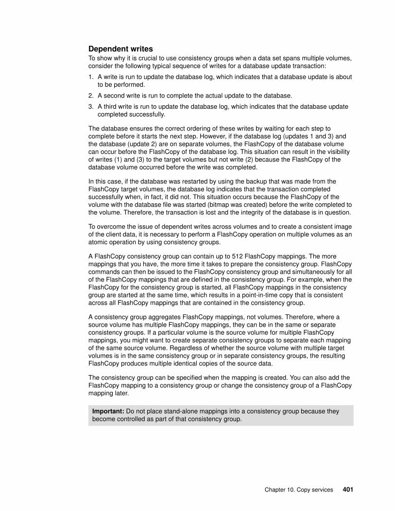
Dependent writesTo show why it is crucial to use consistency groups when a data set spans multiple volumes, consider the following typical sequence of writes for a database update transaction:
1. A write is run to update the database log, which indicates that a database update is about to be performed.
2. A second write is run to complete the actual update to the database.
3. A third write is run to update the database log, which indicates that the database update completed successfully.
The database ensures the correct ordering of these writes by waiting for each step to complete before it starts the next step. However, if the database log (updates 1 and 3) and the database (update 2) are on separate volumes, the FlashCopy of the database volume can occur before the FlashCopy of the database log. This situation can result in the visibility of writes (1) and (3) to the target volumes but not write (2) because the FlashCopy of the database volume occurred before the write was completed.
In this case, if the database was restarted by using the backup that was made from the FlashCopy target volumes, the database log indicates that the transaction completed successfully when, in fact, it did not. This situation occurs because the FlashCopy of the volume with the database file was started (bitmap was created) before the write completed to the volume. Therefore, the transaction is lost and the integrity of the database is in question.
To overcome the issue of dependent writes across volumes and to create a consistent image of the client data, it is necessary to perform a FlashCopy operation on multiple volumes as an atomic operation by using consistency groups.
A FlashCopy consistency group can contain up to 512 FlashCopy mappings. The more mappings that you have, the more time it takes to prepare the consistency group. FlashCopy commands can then be issued to the FlashCopy consistency group and simultaneously for all of the FlashCopy mappings that are defined in the consistency group. For example, when the FlashCopy for the consistency group is started, all FlashCopy mappings in the consistency group are started at the same time, which results in a point-in-time copy that is consistent across all FlashCopy mappings that are contained in the consistency group.
A consistency group aggregates FlashCopy mappings, not volumes. Therefore, where a source volume has multiple FlashCopy mappings, they can be in the same or separate consistency groups. If a particular volume is the source volume for multiple FlashCopy mappings, you might want to create separate consistency groups to separate each mapping of the same source volume. Regardless of whether the source volume with multiple target volumes is in the same consistency group or in separate consistency groups, the resulting FlashCopy produces multiple identical copies of the source data.
The consistency group can be specified when the mapping is created. You can also add the FlashCopy mapping to a consistency group or change the consistency group of a FlashCopy mapping later.
Important: Do not place stand-alone mappings into a consistency group because they become controlled as part of that consistency group.
Chapter 10. Copy services 401

FlashCopy consistency group statesA FlashCopy consistency group is in one of the following states at any point:
� Idle or Copied
All FlashCopy Mappings in this consistency group are in the Idle or Copied state.
� Preparing
At least one FlashCopy mapping in this consistency group is in the Preparing state.
� Prepared
The consistency group is ready to start. While the consistency group is in this state, the target volumes of all FlashCopy mappings in this consistency group are not accessible.
� Copying
At least one FlashCopy mapping in the consistency group is in the Copying state and no FlashCopy mappings are in the Suspended state.
� Stopping
At least one FlashCopy mapping in the consistency group is in the Stopping state and no FlashCopy mappings are in the Copying or Suspended state.
� Stopped
The consistency group is stopped because you issued a command or an I/O error occurred.
� Suspended
At least one FlashCopy mapping in the consistency group is in the Suspended state.
� Empty
The consistency group does not have any FlashCopy mappings.
Reverse FlashCopyReverse FlashCopy enables FlashCopy targets to become restore points for the source without breaking the FlashCopy relationship and without waiting for the original copy operation to complete. It supports multiple targets and multiple rollback points.
A key advantage of Reverse FlashCopy is that it does not delete the original target, allowing processes that use the target, such as a tape backup, to continue uninterrupted.
You can also create an optional copy of the source volume that is made before the reverse copy operation is started. This copy restores the original source data, which can be useful for diagnostic purposes.
402 Implementing the Lenovo Storage V3700 V2 and V5030 Systems
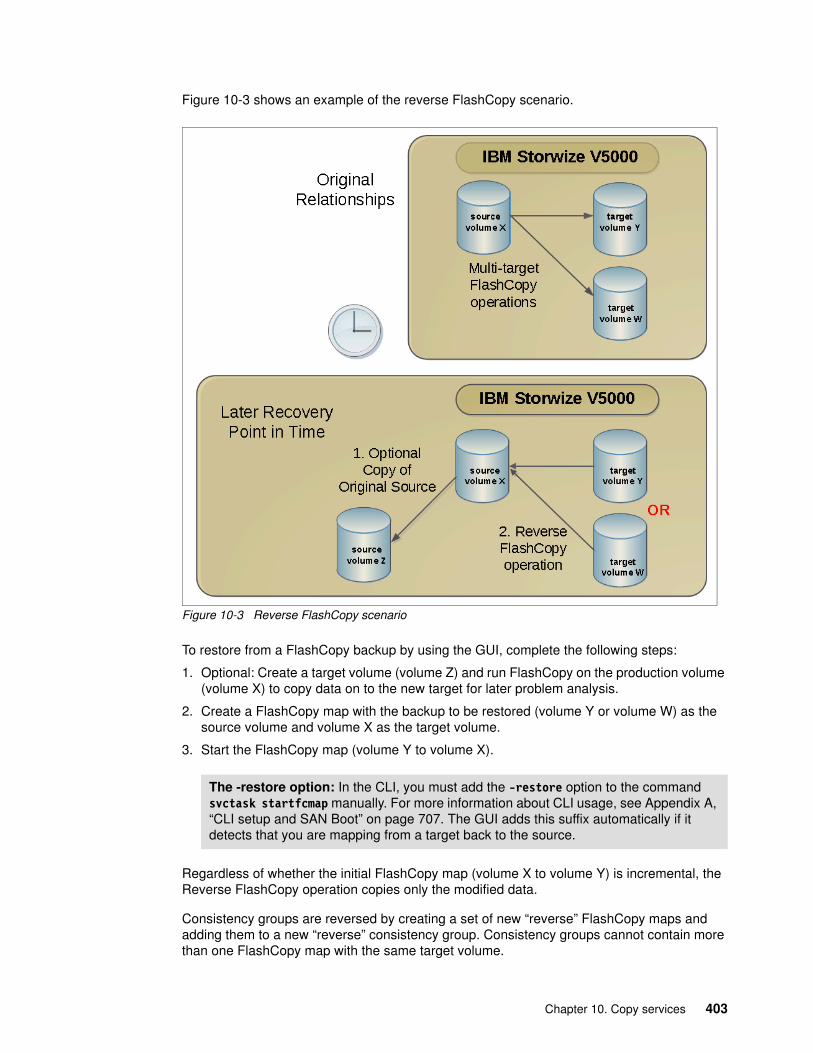
Figure 10-3 shows an example of the reverse FlashCopy scenario.
Figure 10-3 Reverse FlashCopy scenario
To restore from a FlashCopy backup by using the GUI, complete the following steps:
1. Optional: Create a target volume (volume Z) and run FlashCopy on the production volume (volume X) to copy data on to the new target for later problem analysis.
2. Create a FlashCopy map with the backup to be restored (volume Y or volume W) as the source volume and volume X as the target volume.
3. Start the FlashCopy map (volume Y to volume X).
Regardless of whether the initial FlashCopy map (volume X to volume Y) is incremental, the Reverse FlashCopy operation copies only the modified data.
Consistency groups are reversed by creating a set of new “reverse” FlashCopy maps and adding them to a new “reverse” consistency group. Consistency groups cannot contain more than one FlashCopy map with the same target volume.
The -restore option: In the CLI, you must add the -restore option to the command svctask startfcmap manually. For more information about CLI usage, see Appendix A, “CLI setup and SAN Boot” on page 707. The GUI adds this suffix automatically if it detects that you are mapping from a target back to the source.
Chapter 10. Copy services 403

10.1.3 Planning for FlashCopy
Several items, which are described in this section, must be considered before a FlashCopy is performed.
Guidelines for FlashCopy implementationConsider the following guidelines for FlashCopy implementation:
� The source and target volumes must be on the same Lenovo Storage V3700 V2, V3700 V2 XP, and V5030 storage systems.
� The source and target volumes do not need to be in the same storage pool.
� The FlashCopy source and target volumes can be thin-provisioned.
� The source and target volumes must be the same size. The size of the source and target volumes cannot be altered (increased or decreased) while a FlashCopy mapping is defined.
� FlashCopy operations perform in direct proportion to the performance of the source and target disks. If you have a fast source disk and slow target disk, the performance of the source disk is reduced because it must wait for the write operation to occur at the target before it can write to the source.
Maximum configurations for FlashCopyTable 10-2 shows several FlashCopy maximum configurations. For more information about the latest values, see the Lenovo Storage V3700 V2, V3700 V2 XP, and V5030 Information Center at this website:
http://systemx.lenovofiles.com/mobile/help/topic/com.lenovo.storage.v3700.doc/svc_flashcopyovr_20qlge.html
Table 10-2 FlashCopy maximum configurations
FlashCopy property Maximum
FlashCopy targets per source 256
FlashCopy mappings per cluster 4,096
FlashCopy consistency groups per cluster 255
FlashCopy mappings per consistency group 512
404 Implementing the Lenovo Storage V3700 V2 and V5030 Systems

FlashCopy presetsThe Lenovo Storage V3700 V2, V3700 V2 XP, and V5030 storage systems provide three FlashCopy presets (Snapshot, Clone, and Backup) to simplify the more common FlashCopy operations, as shown in Table 10-3.
Table 10-3 FlashCopy presets
Preset Purpose
Snapshot Creates a point-in-time view of the production data. The snapshot is not intended to be an independent copy. Instead, it is used to maintain a view of the production data at the time that the snapshot is created.This preset automatically creates a thin-provisioned target volume with none of the capacity that is allocated at the time of creation. The preset uses a FlashCopy mapping with none of the background copy so that only data that is written to the source or target is copied to the target volume.
Clone Creates an exact replica of the volume, which can be changed without affecting the original volume. After the copy operation completes, the mapping that was created by the preset is automatically deleted.This preset automatically creates a volume with the same properties as the source volume and creates a FlashCopy mapping with a background copy rate of 50. The FlashCopy mapping is configured to automatically delete when the FlashCopy mapping reaches 100% completion.
Backup Creates a point-in-time replica of the production data. After the copy completes, the backup view can be refreshed from the production data, with minimal copying of data from the production volume to the backup volume.This preset automatically creates a volume with the same properties as the source volume. The preset creates an incremental FlashCopy mapping with a background copy rate of 50.
Presets: All of the presets can be adjusted by using the expandable Advanced Settings section in the GUI.
Chapter 10. Copy services 405

10.1.4 Managing FlashCopy by using the GUI
The Lenovo Storage V3700 V2, V3700 V2 XP, and V5030 storage systems provide a separate function icon to access copy service management. The following windows are available for managing FlashCopy under the Copy Services function icon:
� FlashCopy� Consistency groups� FlashCopy Mappings
The Copy Services function icon is shown in Figure 10-4.
Figure 10-4 Copy Services function icon
Most of the actions to manage the FlashCopy mapping can be performed in the FlashCopy window or the FlashCopy Mappings windows, although the quick path to create FlashCopy presets is only in the FlashCopy window.
406 Implementing the Lenovo Storage V3700 V2 and V5030 Systems

Click FlashCopy in the Copy Services function icon menu and the FlashCopy window opens, as shown in Figure 10-5. In the FlashCopy window, the FlashCopy mappings are organized by volumes.
Figure 10-5 FlashCopy window
Click FlashCopy Mappings in the Copy Services function icon menu and the FlashCopy Mappings window opens, as shown in Figure 10-6. In the FlashCopy Mappings window, the FlashCopy mappings are listed individually.
Figure 10-6 FlashCopy Mappings window
Chapter 10. Copy services 407

The Consistency Groups window is used to manage the consistency groups for FlashCopy mappings. Click Consistency Groups in the Copy Services function icon menu and the Consistency Groups window opens, as shown in Figure 10-7.
Figure 10-7 Consistency Groups window
408 Implementing the Lenovo Storage V3700 V2 and V5030 Systems

Quick path to create FlashCopy presetsIt is easy to create a FlashCopy by using the presets in the FlashCopy window.
Creating a snapshotIn the FlashCopy window, choose a volume and click Create Snapshot from the Actions drop-down menu, as shown in Figure 10-8. Alternatively, you can highlight your chosen volume and right-click to access the Actions menu.
Figure 10-8 Create a snapshot by using the preset
You now have a snapshot volume for the volume that you selected.
Chapter 10. Copy services 409

Creating a cloneIn the FlashCopy window, choose a volume and click Create Clone from the Actions drop-down menu, as shown in Figure 10-9. Alternatively, highlight your chosen volume and right-click to access the Actions menu.
Figure 10-9 Create a clone from the preset
You now have a clone volume for the volume that you selected.
410 Implementing the Lenovo Storage V3700 V2 and V5030 Systems

Creating a backupIn the FlashCopy window, choose a volume and click Create Backup from the Actions drop-down menu, as shown in Figure 10-10. Alternatively, highlight your chosen volume and right-click to access the Actions menu.
Figure 10-10 Create a backup from the preset
You now have a backup volume for the volume that you selected.
Chapter 10. Copy services 411

In the FlashCopy window and in the FlashCopy Mappings window, you can monitor the progress of the running FlashCopy operations, as shown in Figure 10-11. The progress bars for each target volume indicate the copy progress as a percentage. The copy progress remains 0% for snapshots. No change occurs until data is written to the target volume. The copy progresses for clone and backup continues to increase until the copy process completes.
Figure 10-11 FlashCopy in progress that is viewed in the FlashCopy Mappings window
The copy progress is also available under the Running Tasks status indicator, as shown in Figure 10-12.
Figure 10-12 Running Tasks bar: FlashCopy operations
412 Implementing the Lenovo Storage V3700 V2 and V5030 Systems

This view is a little different from the FlashCopy and FlashCopy Mapping windows (Figure 10-13).
Figure 10-13 FlashCopy operations that are shown through Running Tasks
After the copy processes are complete, the FlashCopy mapping with the clone preset (Gen_Ent_Vol_1 in our example) was deleted automatically, as shown in Figure 10-14. Two identical volumes that are independent of each other now exist.
Figure 10-14 FlashCopy processes are complete
Chapter 10. Copy services 413

10.1.5 Managing FlashCopy mappings
The FlashCopy presets cover the most frequently used FlashCopy configurations for general situations. However, customized FlashCopy mappings are still necessary in certain complicated scenarios.
Creating FlashCopy mappingsYou can create FlashCopy mappings through the FlashCopy window. Select the volume that you want to be the source volume for the FlashCopy mapping and click Advanced FlashCopy from the Actions drop-down menu, as shown in Figure 10-15. Alternatively, select the volume and right-click.
Figure 10-15 Create an advanced FlashCopy
You can select “Create New Target Volumes” as part of the mapping process or “Use Existing Target Volumes”. We describe the process to create volumes next. To use existing volumes, see “Using existing target volumes” on page 422.
414 Implementing the Lenovo Storage V3700 V2 and V5030 Systems

Creating target volumesComplete the following steps to create target volumes:
1. Click Create new target volumes if you did not create the target volume.
2. The wizard guides you to choose a preset, as shown in Figure 10-16. Choose one preset with the most similar configuration to the configuration that you require and click Advanced Settings to adjust any advanced settings.
Figure 10-16 Choose a preset that is the most similar to your requirement
Chapter 10. Copy services 415

The following default advanced settings for the snapshot preset are shown in Figure 10-17:
– Background Copy Rate: 0– Incremental: No– Delete mapping after completion (Auto Delete after completion): No– Cleaning Rate: 0
Figure 10-17 Default setting for the snapshot preset
416 Implementing the Lenovo Storage V3700 V2 and V5030 Systems

The following Advanced Settings for the clone preset are shown in Figure 10-18:
– Background Copy Rate: 50– Incremental: No– Delete mapping after completion (Auto Delete after completion): Yes– Cleaning Rate: 50
Figure 10-18 Default settings for the clone preset
Chapter 10. Copy services 417

Figure 10-19 shows the following Advanced Settings for the Backup preset:
– Background Copy Rate: 50– Incremental: Yes– Delete mapping after completion (Auto Delete after completion): No– Cleaning Rate: 50
Figure 10-19 Default settings for the backup preset
418 Implementing the Lenovo Storage V3700 V2 and V5030 Systems

3. Change the settings of the FlashCopy mapping according to your requirements and click Next.
4. In the next step, you can add your FlashCopy mapping to a consistency group, as shown in Figure 10-20. If the consistency group is not ready, the FlashCopy mapping can be added to the consistency group later. Click Next.
Figure 10-20 Add FlashCopy mapping to a consistency group
Chapter 10. Copy services 419

5. You can define how the new target volumes manage capacity, as shown in Figure 10-21. The “Create a generic volume” option is your default choice if you selected Clone or Backup as your basic preset. If you select a thin-provisioned volume, more options are available, as shown in Figure 10-22. The other option is “Inherit properties from source volume”.
Figure 10-21 Defining how target volumes use capacity
Figure 10-22 Advanced thin-provisioning options
420 Implementing the Lenovo Storage V3700 V2 and V5030 Systems

6. You can choose from which storage pool you want to create your target volume, as shown in Figure 10-23. You can select the same storage pool that is used by the source volume or a different pool. Click Next.
Figure 10-23 Selecting a storage pool for target volume
7. Click Finish when you make your decision, and the mappings and volume are created.
8. Click Close to see the FlashCopy mapping that is created on your volume with a new target, as shown in Figure 10-24. The status of the new FlashCopy mapping is Idle. It can be started, as described in “Starting a FlashCopy mapping” on page 427.
Figure 10-24 FlashCopy mapping is created with a new target
Chapter 10. Copy services 421

Using existing target volumesComplete the following steps to use existing target volumes:
1. If candidate target volumes exist, select Use Existing Target Volumes in the Advanced FlashCopy menu, as shown in Figure 10-25.
Figure 10-25 Create FlashCopy mapping by using existing target volumes
422 Implementing the Lenovo Storage V3700 V2 and V5030 Systems

2. You must choose the target volume for the source volume that you selected. Select the target volume from the drop-down list in the right pane of the window and click Add, as shown in Figure 10-26.
Figure 10-26 Select the target volume
Chapter 10. Copy services 423

3. After you click Add, the FlashCopy mapping is listed, as shown in Figure 10-27. Click the red X to delete the FlashCopy mapping if the FlashCopy mapping is not the one you want to create. You can create additional mappings by selecting more source and target volumes from the drop-down boxes and clicking Add. After all of the FlashCopy mappings that you want are defined, click Next.
Figure 10-27 Add FlashCopy mapping
424 Implementing the Lenovo Storage V3700 V2 and V5030 Systems

4. Select the preset and (if necessary) adjust the settings by using the Advanced Settings section as shown in Figure 10-28. (For more information about the advanced setting, see “Creating target volumes” on page 415.) Confirm that the settings meet your requirements and then click Next.
Figure 10-28 Select a preset and make your adjustments
Chapter 10. Copy services 425

5. You can now add the FlashCopy mapping to a consistency group (if necessary), as shown in Figure 10-29. Selecting Yes shows a drop-down list from which you can select a consistency group. Click Finish and the FlashCopy mapping is created with the status of Idle, as shown in Figure 10-24 on page 421.
Figure 10-29 Select a consistency group to add the FlashCopy mapping
Creating FlashCopy mappingsYou can also create FlashCopy mappings in the FlashCopy Mappings window by clicking Create FlashCopy Mapping in the upper left, as shown in Figure 10-30.
Figure 10-30 Create a FlashCopy mapping in the FlashCopy Mappings window
426 Implementing the Lenovo Storage V3700 V2 and V5030 Systems

A wizard guides you through the process to create a FlashCopy mapping. The steps are the same as creating an Advanced FlashCopy mapping by using existing target volumes, as described in “Using existing target volumes” on page 422.
Starting a FlashCopy mappingMost of the FlashCopy mapping actions can be performed in the FlashCopy window or the FlashCopy Mapping window. For the actions that are available in both windows, in the following sections, we show the steps in the FlashCopy window, although the steps are the same if you use the FlashCopy Mapping window.
You can start the mapping by selecting the FlashCopy target volume in the FlashCopy window and by selecting Start from the Actions drop-down menu (as shown in Figure 10-31) or by selecting the volume and right-clicking. The status of the FlashCopy mapping changes from Idle to Copying.
Figure 10-31 Start FlashCopy mapping
Chapter 10. Copy services 427

Stopping a FlashCopy mappingThe FlashCopy mapping can be stopped by selecting the FlashCopy target volume in the FlashCopy window and clicking Stop from the Actions drop-down menu, as shown in Figure 10-32. After the stopping process completes, the status of the FlashCopy mapping is changed to Stopped.
Figure 10-32 Stopping a FlashCopy mapping
428 Implementing the Lenovo Storage V3700 V2 and V5030 Systems

Renaming the target volumeIf the FlashCopy target volumes were created automatically by the Lenovo Storage V3700 V2, V3700 V2 XP, and V5030 storage systems, the name of the target volume is the source volume name plus a suffix that includes numbers. The name of the target volumes can be changed to be more meaningful in your environment.
To change the name of the target volume, select the FlashCopy target volume in the FlashCopy window and click Rename Target Volume from the Actions drop-down menu (as shown in Figure 10-33) or right-click the selected volume.
Figure 10-33 Rename a target volume
Chapter 10. Copy services 429

Enter your new name for the target volume, as shown in Figure 10-34. Click Rename to finish.
Figure 10-34 Rename a target volume
430 Implementing the Lenovo Storage V3700 V2 and V5030 Systems

Renaming a FlashCopy mappingThe FlashCopy mappings are created with names that begin with fcmap. You can change this name to a more meaningful name for your environment.
To change the name of a FlashCopy mapping, select the FlashCopy mapping in the FlashCopy Mappings window and click Rename Mapping in the Actions drop-down menu, as shown in Figure 10-35.
Figure 10-35 Rename a FlashCopy mapping
Chapter 10. Copy services 431

Enter the new name for the FlashCopy mapping, as shown in Figure 10-36. Click Rename to finish.
Figure 10-36 Enter a new name for the FlashCopy mapping
Deleting a FlashCopy mappingThe FlashCopy mapping can be deleted by selecting the FlashCopy target volume in the FlashCopy window and by clicking Delete Mapping in the Actions drop-down menu (as shown in Figure 10-37) or by right-clicking the selected volume.
Figure 10-37 Select Delete Mapping
432 Implementing the Lenovo Storage V3700 V2 and V5030 Systems

You must confirm your action to delete FlashCopy mappings in the window that opens, as shown in Figure 10-38. Verify the number of FlashCopy mappings that you want to delete. If you want to delete the FlashCopy mappings while the data on the target volume is inconsistent with the source volume, select “Delete the FlashCopy mapping even when the data on the target volume is inconsistent, or if the target volume has other dependencies”. Click Delete and your FlashCopy mapping is removed.
Figure 10-38 Confirm the deletion of FlashCopy mappings
FlashCopy Mapping state: If the FlashCopy mapping is in the Copying state, it must be stopped before it is deleted.
Deleting a FlashCopy mapping: Deleting the FlashCopy mapping does not delete the target volume. If you must reclaim the storage space that is occupied by the target volume, you must delete the target volume manually.
Chapter 10. Copy services 433

Showing related volumesYou can show the FlashCopy mapping dependencies by selecting a target or source volume in the FlashCopy window and clicking Show Related Volumes in the Actions drop-down menu (as shown in Figure 10-39) or by right-clicking the selected volume.
Figure 10-39 Show Related Volumes menu
The FlashCopy mapping dependency tree opens, as shown in Figure 10-40.
Figure 10-40 FlashCopy mapping dependency tree
434 Implementing the Lenovo Storage V3700 V2 and V5030 Systems

Clicking either volume shows the properties of the volume, as shown in Figure 10-41.
Figure 10-41 Target FlashCopy volume details
Chapter 10. Copy services 435
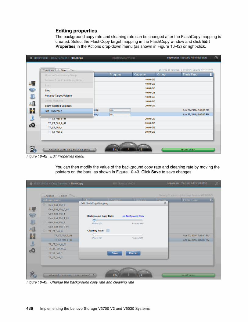
Editing propertiesThe background copy rate and cleaning rate can be changed after the FlashCopy mapping is created. Select the FlashCopy target mapping in the FlashCopy window and click Edit Properties in the Actions drop-down menu (as shown in Figure 10-42) or right-click.
Figure 10-42 Edit Properties menu
You can then modify the value of the background copy rate and cleaning rate by moving the pointers on the bars, as shown in Figure 10-43. Click Save to save changes.
Figure 10-43 Change the background copy rate and cleaning rate
436 Implementing the Lenovo Storage V3700 V2 and V5030 Systems

Restoring from a FlashCopyComplete the following steps to manipulate FlashCopy target volumes to restore a source volume to a previous known state:
1. Identify the FlashCopy relationship that you want to restore. In our example, we want to restore FlashVol1, as shown in Figure 10-44.
Figure 10-44 Starting FlashCopy restore
2. Create a mapping by using the target volume of the mapping to be restored. In our example, it is FlashVol1_01, as shown in Figure 10-45. Select Advanced FlashCopy → Use Existing Target Volumes.
Figure 10-45 Create a reverse mapping
Chapter 10. Copy services 437

3. The source volume is preselected with the target volume that was selected in the previous step. Select the target volume from the drop-down list. (You select the source volume that you want to restore.) In our example, we select FlashVol1, as shown in Figure 10-46.
Figure 10-46 Select a target volume
4. Click Add. A warning message appears, as shown in Figure 10-47. Click Close. This message is shown because we are using a source as a target.
Figure 10-47 FlashCopy mapping restore warning
438 Implementing the Lenovo Storage V3700 V2 and V5030 Systems

5. Click Next to see a snapshot preset choice, as shown in Figure 10-48.
Figure 10-48 Choose snapshot preset
Select Snapshot and click Next.
6. In the Create FlashCopy Mapping window, you are asked whether the new mapping is to be part of a consistency group, as shown in Figure 10-49. In our example, the new mapping is not part of a consistency group, so we click No, do not add the mappings to a consistency group and then select Finish to create the mapping.
Figure 10-49 Prompt to add the mapping to consistency group
Chapter 10. Copy services 439

7. The reverse mapping is now created and shown in the Idle state, as shown in Figure 10-50.
Figure 10-50 New reverse mapping
8. To restore the original source volume FlashVol1 with the snapshot that we took (FlashVol1_01), we select the new mapping and right-click to open the Actions menu, as shown in Figure 10-51.
Figure 10-51 Starting the reverse mapping
440 Implementing the Lenovo Storage V3700 V2 and V5030 Systems

9. Click Start to write over FlashVol1 with the original bitmap data that was saved in the FlashCopy FlashVol01_01. The command then completes, as shown in Figure 10-52.
Figure 10-52 FlashCopy restore command
10.The reverse mapping now shows as 100% copied, as shown in Figure 10-53.
Figure 10-53 Source volume restore complete
Important: The underlying command that is run by the Lenovo Storage V3700 V2, V3700 V2 XP, and V5030 append the -restore option automatically.
Chapter 10. Copy services 441

10.1.6 Managing a FlashCopy consistency group
FlashCopy consistency groups can be managed by clicking Consistency Groups under the Copy Services function icon, as shown in Figure 10-54.
Figure 10-54 Access to the Consistency Groups window
Use the Consistency Groups window to manage consistency groups and FlashCopy mappings.
Consistency Groups windowAll FlashCopy mappings are shown. Both the FlashCopy mappings that are in consistency groups and FlashCopy mappings that are not in consistency groups are shown. Click Not in a Group, and then expand your selection by clicking the plus sign (+) icon next to it. All of the FlashCopy mappings that are not in any consistency groups are displayed underneath.
Individual consistency groups are displayed underneath those FlashCopy mappings that are not in groups. You can discover the properties of a consistency group and the FlashCopy mappings that are in it by clicking the plus sign (+) icon to the left of the consistency group name. You can also act on any consistency groups and FlashCopy mappings within the Consistency Groups window, if their state allows action. For more information, see 10.1.5, “Managing FlashCopy mappings” on page 414.
442 Implementing the Lenovo Storage V3700 V2 and V5030 Systems

Creating a FlashCopy consistency groupTo create a FlashCopy consistency group, click Create Consistency Group at the top of the Consistency Groups window, as shown in Figure 10-55.
Figure 10-55 New Consistency Group option
You are prompted to enter the name of the new consistency group. Follow your naming conventions to enter the name of the new consistency group in the name field and click Create.
After the creation process completes, the new consistency group is displayed, as shown in Figure 10-56.
Figure 10-56 New consistency group
Chapter 10. Copy services 443

You can rename the consistency group by selecting it and then right-clicking or by using the Actions drop-down menu. Select Rename and enter the new name, as shown in Figure 10-57. Next to the name of the consistency group, the state shows that it is now an empty consistency group with no FlashCopy mappings in it.
Figure 10-57 Renaming a consistency group
Adding FlashCopy mappings to a consistency groupClick Not in a Group to list all of the FlashCopy mappings with no consistency group. You can add FlashCopy mappings to a consistency group by selecting the FlashCopy mappings and clicking Move to Consistency Group from the Actions drop-down menu, as shown in Figure 10-58.
Figure 10-58 Select the FlashCopy mappings to add to a consistency group
444 Implementing the Lenovo Storage V3700 V2 and V5030 Systems
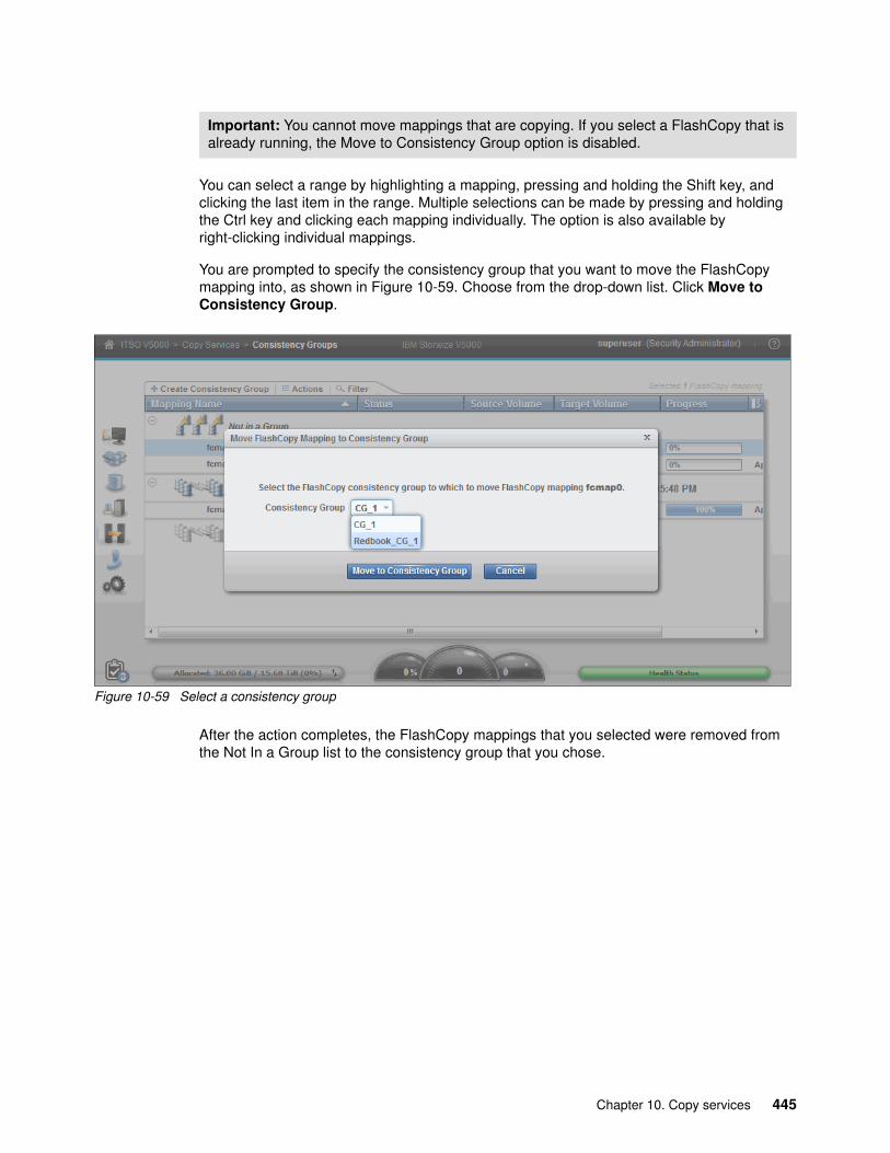
You can select a range by highlighting a mapping, pressing and holding the Shift key, and clicking the last item in the range. Multiple selections can be made by pressing and holding the Ctrl key and clicking each mapping individually. The option is also available by right-clicking individual mappings.
You are prompted to specify the consistency group that you want to move the FlashCopy mapping into, as shown in Figure 10-59. Choose from the drop-down list. Click Move to Consistency Group.
Figure 10-59 Select a consistency group
After the action completes, the FlashCopy mappings that you selected were removed from the Not In a Group list to the consistency group that you chose.
Important: You cannot move mappings that are copying. If you select a FlashCopy that is already running, the Move to Consistency Group option is disabled.
Chapter 10. Copy services 445

Starting a consistency groupTo start a consistency group, highlight the required group and click Start from the Actions drop-down menu or right-click the consistency group, as shown in Figure 10-60.
Figure 10-60 Start a consistency group
After you start the consistency group, all of the FlashCopy mappings in the consistency group start at the same time. The state of consistency group and all of the underlying mappings changes to Copying, as shown in Figure 10-61.
Figure 10-61 Consistency group started
446 Implementing the Lenovo Storage V3700 V2 and V5030 Systems

Stopping a consistency groupThe consistency group can be stopped by selecting Stop from the Actions drop-down menu or right-clicking the consistency group, as shown in Figure 10-62.
Figure 10-62 Stop a consistency group
After the stop process completes, the FlashCopy mappings in the consistency group are in the Stopped state and a red X icon appears on the function icon of this consistency group to indicate an alert, as shown in Figure 10-63.
Figure 10-63 Stopping consistency group process completes
Chapter 10. Copy services 447

Any previously copied relationships that were added to a consistency group that was later stopped before all members of the consistency group completed synchronization remain in the Copied state.
Removing FlashCopy mappings from a consistency groupFlashCopy mappings can be removed from a consistency group by selecting the FlashCopy mappings and clicking Remove from Consistency Group from the Actions drop-down menu of the FlashCopy mapping or by right-clicking the FlashCopy mapping, as shown in Figure 10-64.
Figure 10-64 Remove from consistency group
The FlashCopy mappings are returned to the Not in a Group list after they are removed from the consistency group.
448 Implementing the Lenovo Storage V3700 V2 and V5030 Systems

Deleting a consistency groupA consistency group can be deleted by clicking Delete from the Actions drop-down menu or by right-clicking the selected consistency group, as shown in Figure 10-65.
Figure 10-65 Delete a consistency group
You are presented with a confirmation window, as shown in Figure 10-66.
Figure 10-66 Confirming the deletion of a consistency group
Click Yes to delete the group. Consistency groups do not need to be empty to be deleted. Any FlashCopy mappings that exist in the consistency group are moved to the Not in a Group mappings list when the consistency group is deleted.
Chapter 10. Copy services 449

Restoring from a FlashCopy consistency groupYou can manipulate FlashCopy mappings that were captured as part of a consistency group to restore the source volumes of those mappings to the state they were all in at the time that the FlashCopy was taken.
To restore a consistency group from a FlashCopy, we must create a reverse mapping of all of the individual volumes that were contained within the original consistency group. In our example, two FlashCopy mappings (fcmap0 and fcmap1) are in a consistency group that is known as FlashTestGroup, as shown in Figure 10-67.
Figure 10-67 Creating FlashCopy reverse mapping
Complete the following steps:
1. Click New Consistency Group in the upper-left corner (as shown in Figure 10-67) and create a consistency group. In our example, we created a consistency group that is called RedBookTest.
450 Implementing the Lenovo Storage V3700 V2 and V5030 Systems

2. Follow the procedure that is described in “Restoring from a FlashCopy” on page 437 to create a reverse mapping for each mapping in the source consistency group (FlashTestGroup). When you are prompted to add to a consistency group (as shown in Figure 10-49 on page 439), select Yes. From the drop-down list, select the new “reverse” consistency group that you created in step 1. In our example, this consistency group is RedBookTest.
The result is similar to the result that is shown in Figure 10-68.
Figure 10-68 Reverse consistency group was populated
Chapter 10. Copy services 451

3. To restore the consistency group, highlight the reverse consistency group and click Start, as shown in Figure 10-69.
Figure 10-69 Starting the consistency group restore
4. This consistency group overwrites Gen_Ent_Vol_0 and Gen_Ent_Vol_1 with the original bitmap data that was saved in the FlashTestGroup FlashCopy consistency group mapping. The command completes, as shown in Figure 10-70.
Figure 10-70 Consistency group restore command
452 Implementing the Lenovo Storage V3700 V2 and V5030 Systems

5. Click Close and the command panel returns to the Consistency Groups window. The reverse consistency group now shows as 100% copied, and all volumes in the original FlashTestGroup are restored, as shown in Figure 10-71.
Figure 10-71 Consistency group was restored
10.2 Remote Copy
In this section, we describe how the Remote Copy function works in Lenovo Storage V3700 V2, V3700 V2 XP, and V5030. We also provide the implementation steps for Remote Copy configuration and management by using the GUI.
Remote Copy consists of three methods for copying: Metro Mirror, Global Mirror, and Global Mirror with Change Volumes. Metro Mirror is designed for metropolitan distances with a synchronous copy requirement. Global Mirror is designed for longer distances without requiring the hosts to wait for the full round-trip delay of the long-distance link through asynchronous methodology. Global Mirror with Change Volumes is an added piece of functionality for Global Mirror that is designed to attain consistency on lower-quality network links.
Metro Mirror and Global Mirror are IBM terms for the functions of Synchronous Remote Copy and Asynchronous Remote Copy. Throughout this book, the term “Remote Copy” is used to refer to both functions where the text applies to each term equally.
Important: The Lenovo Storage V3700 V2, V3700 V2 XP, and V5030 automatically append the -restore option to the command.
Chapter 10. Copy services 453

10.2.1 Remote Copy concepts
Remote Copy concepts are described in this section.
PartnershipWhen a partnership is created, we connect two separate Lenovo Storage V3700 V2, V3700 V2 XP, and V5030 systems, IBM Storwize V3700 for Lenovo, or IBM Storwize V7000 for Lenovo, and an IBM Storwize V5000 for Lenovo. After the partnership creation is configured on both systems, further communication between the node canisters in each of the storage systems is established and maintained by the storage area network (SAN). All inter-cluster communication goes through the Fibre Channel (FC) network.
The partnership must be defined on both participating Storwize system to make the partnership fully functional.
Introduction to layersThe Lenovo Storage V3700 V2, V3700 V2 XP, and V5030 implement the concept of layers. Layers determine how the Lenovo Storage V series portfolio interacts with the IBM Spectrum Virtualize. Two layers, replication and storage, exist.
You use the replication layer when you want to use the Lenovo Storage V3700 V2, V3700 V2 XP, and V5030 with one or more IBM Spectrum Virtualize systems as a Remote Copy partner. The storage layer is the default mode of operation for the Lenovo Storage V3700 V2, V3700 V2 XP, and V5030. You use the storage layer when you want to use the Lenovo Storage V3700 V2, V3700 V2 XP, and V5030 to present storage to an IBM Spectrum Virtualize as a back-end system.
The layer for the Lenovo Storage V3700 V2, V3700 V2 XP, and V5030 can be switched by running svctask chsystem -layer replication. Generally, switch the layer while your Lenovo Storage V3700 V2, V3700 V2 XP, and V5030 systems are not in production. This situation prevents potential disruptions because layer changes are not I/O-tolerant.
Interconnection: Interconnections between the IBM Storwize for Lenovo products were introduced in Version 6.3.0. Any other Storwize for Lenovo product must be at a minimum level of 6.3.0 to connect to the Lenovo Storage V3700 V2, V3700 V2 XP, and V5030, and the Lenovo Storage V3700 V2, V3700 V2 XP, and V5030 must set the replication layer by using the svctask chsystem -layer replication command. Layer limitations are described next.
454 Implementing the Lenovo Storage V3700 V2 and V5030 Systems

Figure 10-72 shows the effect of layers on the IBM Spectrum Virtualize (SVC) and the Lenovo Storage V3700 V2, V3700 V2 XP, and V5030 partnerships.
Figure 10-72 Lenovo Storage V3700 V2, V3700 V2 XP, and V5030 (IBM Storwize V5000) virtualization layers
The replication layer allows an Lenovo Storage V3700 V2, V3700 V2 XP, and V5030 systems to be a Remote Copy partner with an IBM Spectrum Virtualize.
Limitations on the Spectrum Virtualize and Lenovo Storage V3700 V2, V3700 V2 XP, and V5030 partnerships
The IBM Spectrum Virtualize and Lenovo Storage V3700 V2, V3700 V2 XP, and V5030 systems can be partners in a Remote Copy partnership. However, the following limitations apply:
� The layer for the Lenovo Storage V3700 V2, V3700 V2 XP, and V5030 must be set to replication. The default is storage.
� If any other Spectrum Virtualize or Lenovo Storage V3700 V2, V3700 V2 XP, and V5030 ports are visible on the SAN (other than the ports on the cluster that you change), you cannot change the layer.
� If any host object is defined to an IBM Spectrum Virtualize or Lenovo Storage V3700 V2, V3700 V2 XP, and V5030 systems, you cannot change the layer.
� If any MDisks from an Lenovo Storage V3700 V2, V3700 V2 XP,and V5030, other than the MDisk on which you are making the layer change, are visible, you cannot change the layer.
� If any cluster partnership is defined, you cannot change the layer.
Partnership topologiesA partnership between up to four Lenovo Storage V3700 V2, V3700 V2 XP, and V5030 systems is allowed.
The following typical partnership topologies between multiple Lenovo Storage V3700 V2, V3700 V2 XP, and V5030 are available:
� Daisy-chain topology, as shown in Figure 10-73 on page 456
Chapter 10. Copy services 455

Figure 10-73 Daisy chain partnership topology for the Lenovo Storage V3700 V2, V3700 V2 XP, and V5030 (IBM Storwize V5000)
� Triangle topology, as shown in Figure 10-74
Figure 10-74 Triangle partnership topology for the Lenovo Storage V3700 V2, V3700 V2 XP, and V5030 (IBM Storwize V5000)
� Star topology, as shown in Figure 10-75
Figure 10-75 Star topology for the Lenovo Storage V3700 V2, V3700 V2 XP, and V5030 (IBM Storwize V5000)
456 Implementing the Lenovo Storage V3700 V2 and V5030 Systems

� Full-meshed topology, as shown in Figure 10-76
Figure 10-76 Full-meshed Lenovo Storage V3700 V2, V3700 V2 XP, and V5030 (IBM Storwize V5000)
Partnership statesA partnership has the following states:
� Partially Configured
Indicates that only one cluster partner is defined from a local or remote cluster to the displayed cluster and is started. For the displayed cluster to be configured fully and to complete the partnership, you must define the cluster partnership from the cluster that is displayed to the corresponding local or remote cluster.
� Fully Configured
Indicates that the partnership is defined on the local and remote clusters and is started.
� Remote Not Present
Indicates that the remote cluster is not present for the partnership.
� Partially Configured (Local Stopped)
Indicates that the local cluster is only defined to the remote cluster and the local cluster is stopped.
� Fully Configured (Local Stopped)
Indicates that a partnership is defined on the local and remote clusters and the remote cluster is present, but the local cluster is stopped.
� Fully Configured (Remote Stopped)
Indicates that a partnership is defined on the local and remote clusters and the remote cluster is present, but the remote cluster is stopped.
� Fully Configured (Local Excluded)
Indicates that a partnership is defined between a local and remote cluster. However, the local cluster was excluded. This state can occur when the fabric link between the two
Partnerships: These partnerships are valid for configurations with the SAN Volume Controllers and Lenovo Storage V3700 V2, V3700 V2 XP, and V5030 systems if the Lenovo Storage V3700 V2, V3700 V2 XP, and V5030 systems are using the replication layer. They are also valid for the OBM Storwize V3700 and V7000 for Lenovo products.
Chapter 10. Copy services 457

clusters was compromised by too many fabric errors or by the slow response times of the cluster partnership.
� Fully Configured (Remote Excluded)
Indicates that a partnership is defined between a local and remote cluster. However, the remote cluster was excluded. This state can occur when the fabric link between the two clusters was compromised by too many fabric errors or by the slow response times of the cluster partnership.
� Fully Configured (Remote Exceeded)
Indicates that a partnership is defined between a local and remote cluster and the remote is available. However, the remote cluster exceeds the number of allowed clusters within a cluster network. The maximum of four clusters can be defined in a network. If the number of clusters exceeds that limit, the Lenovo Storage V3700 V2, V3700 V2 XP, and V5030 systems determine the inactive cluster or clusters by sorting all of the clusters by their unique identifier in numerical order. The inactive cluster partner that is not in the top four of the cluster-unique identifiers shows Fully Configured (Remote Exceeded).
Remote Copy relationshipsA Remote Copy relationship is a relationship between two individual volumes of the same size. These volumes are called a master (source) volume and an auxiliary (target) volume.
Typically, the master volume contains the production copy of the data, and it is the volume that the application normally accesses. The auxiliary volume often contains a backup copy of the data, and it is used for disaster recovery (DR).
The master and auxiliary volumes are defined when the relationship is created, and these attributes never change. However, either volume can operate in the primary or secondary role, as necessary. The primary volume contains a valid copy of the application data and receives updates from the host application, which is analogous to a source volume. The secondary volume receives a copy of any updates to the primary volume because these updates are all transmitted across the mirror link.
Therefore, the secondary volume is analogous to a continuously updated target volume. When a relationship is created, the master volume is assigned the role of primary volume and the auxiliary volume is assigned the role of secondary volume. The initial copying direction is from master to auxiliary. When the relationship is in a consistent state, you can reverse the copy direction.
The two volumes in a relationship must be the same size. The Remote Copy relationship can be established on the volumes within one Lenovo Storage V3700 V2, V3700 V2 XP, and V5030 storage systems, which is called an intra-cluster relationship. The relationship can also be established in different Lenovo Storage V3700 V2, V3700 V2 XP, and V5030 storage systems or between an Lenovo Storage V3700 V2, V3700 V2 XP, and V5030 storage systems and an IBM Spectrum Virtualize, IBM Storwize V3700 for Lenovo, or IBM Storwize V7000 for Lenovo, which are called inter-cluster relationships.
Metro MirrorMetro Mirror is a type of Remote Copy that creates a synchronous copy of data from a master volume to an auxiliary volume. With synchronous copies, host applications write to the master volume but they do not receive confirmation that the write operation is complete until
Important: The use of Remote Copy target volumes as Remote Copy source volumes is not allowed. A FlashCopy target volume can be used as a Remote Copy source volume and also as a Remote Copy target volume.
458 Implementing the Lenovo Storage V3700 V2 and V5030 Systems

the data is written to the auxiliary volume. This action ensures that both volumes contain identical data when the copy completes. After the initial copy completes, the Metro Mirror function always maintains a fully synchronized copy of the source data at the target site.
Figure 10-77 shows how a write to the master volume is mirrored to the cache of the auxiliary volume before an acknowledgement of the write is sent back to the host that issued the write. This process ensures that the auxiliary is synchronized in real time if it is needed in a failover situation.
Figure 10-77 Write on a volume in a Metro Mirror relationship
The Metro Mirror function supports copy operations between volumes that are separated by distances up to 300 km (186.4 miles). For disaster recovery, Metro Mirror provides the simplest way to maintain an identical copy on the primary and secondary volumes. However, as with all synchronous copies over remote distances, the performance of host applications can be affected. This performance impact relates to the distance between the primary and secondary volumes and, depending on application requirements, its use might be limited based on the distance between sites.
Global MirrorGlobal Mirror provides an asynchronous copy, which means that the secondary volume is not an exact match of the primary volume at every point. The Global Mirror function provides the same function as Metro Mirror Remote Copy without requiring the hosts to wait for the full round-trip delay of the long-distance link. However, a delay can be seen on the hosts in congested or overloaded environments. Ensure that you closely monitor and understand your workload.
In asynchronous Remote Copy (which Global Mirror provides), write operations are completed on the primary site and the write acknowledgement is sent to the host before it is received at the secondary site. An update of this write operation is sent to the secondary site at a later stage, which provides the capability to perform Remote Copy over distances that exceed the limitations of synchronous Remote Copy.
The distance of Global Mirror replication is limited primarily by the latency of the wide area network (WAN) link that is provided. Global Mirror requires an 80 ms round-trip time for data that is sent to the remote location. The propagation delay is roughly 8.2 μs per mile or 5 μs
Chapter 10. Copy services 459
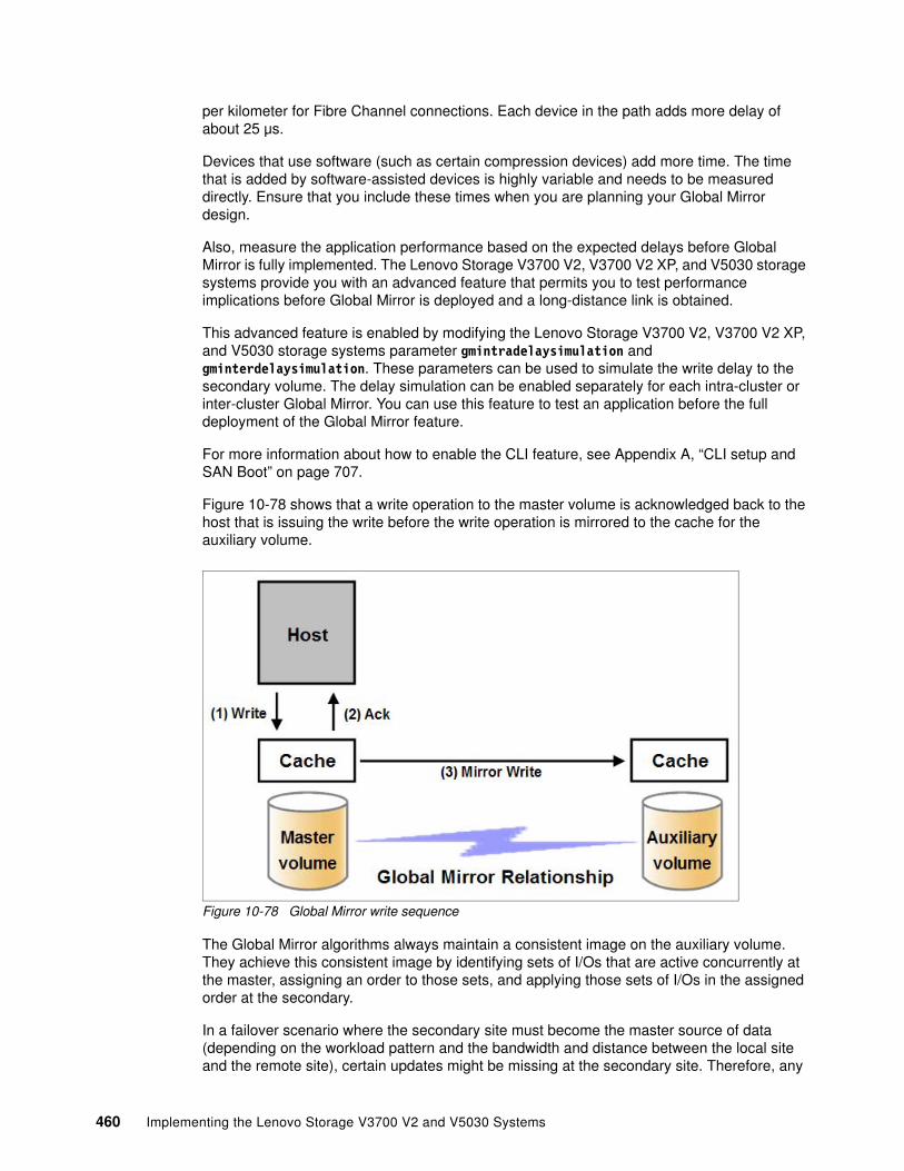
per kilometer for Fibre Channel connections. Each device in the path adds more delay of about 25 μs.
Devices that use software (such as certain compression devices) add more time. The time that is added by software-assisted devices is highly variable and needs to be measured directly. Ensure that you include these times when you are planning your Global Mirror design.
Also, measure the application performance based on the expected delays before Global Mirror is fully implemented. The Lenovo Storage V3700 V2, V3700 V2 XP, and V5030 storage systems provide you with an advanced feature that permits you to test performance implications before Global Mirror is deployed and a long-distance link is obtained.
This advanced feature is enabled by modifying the Lenovo Storage V3700 V2, V3700 V2 XP, and V5030 storage systems parameter gmintradelaysimulation and gminterdelaysimulation. These parameters can be used to simulate the write delay to the secondary volume. The delay simulation can be enabled separately for each intra-cluster or inter-cluster Global Mirror. You can use this feature to test an application before the full deployment of the Global Mirror feature.
For more information about how to enable the CLI feature, see Appendix A, “CLI setup and SAN Boot” on page 707.
Figure 10-78 shows that a write operation to the master volume is acknowledged back to the host that is issuing the write before the write operation is mirrored to the cache for the auxiliary volume.
Figure 10-78 Global Mirror write sequence
The Global Mirror algorithms always maintain a consistent image on the auxiliary volume. They achieve this consistent image by identifying sets of I/Os that are active concurrently at the master, assigning an order to those sets, and applying those sets of I/Os in the assigned order at the secondary.
In a failover scenario where the secondary site must become the master source of data (depending on the workload pattern and the bandwidth and distance between the local site and the remote site), certain updates might be missing at the secondary site. Therefore, any
460 Implementing the Lenovo Storage V3700 V2 and V5030 Systems

applications that use this data must have an external mechanism for recovering the missing updates and reapplying them, for example, a transaction log replay.
10.2.2 Global Mirror with Change Volumes
Global Mirror is designed to achieve a recovery point objective (RPO) as low as possible so that data is as up-to-date as possible. This capability places several strict requirements on your infrastructure. In certain situations (with low network link quality or congested or overloaded hosts), you might be affected by multiple 1920 (congestion) errors.
Congestion errors happen in the following primary situations:
� Congestion at the source site through the host or network� Congestion in the network link or network path� Congestion at the target site through the host or network
Global Mirror includes functionality to address the following conditions that negatively affect certain Global Mirror implementations:
� Estimation of bandwidth requirements tends to be complex.� It is often difficult to ensure that the latency and bandwidth requirements can be met.� Congested hosts on the source or target site can cause disruption.� Congested network links can cause disruption with only intermittent peaks.
To address these issues, change volumes were added as an option for Global Mirror relationships. Change volumes use the FlashCopy functionality but cannot be manipulated as FlashCopy volumes because they are special-purpose only. Change volumes replicate point-in-time images on a cycling period (the default is 300 seconds). This situation means that your change rate must include only the condition of the data at the point in time that the image was taken instead of all of the updates during the period. This situation can provide significant reductions in replication volumes.
Figure 10-79 shows a basic Global Mirror relationship without change volumes.
Figure 10-79 Global Mirror without change volumes
Chapter 10. Copy services 461

Figure 10-80 shows a Global Mirror relationship with change volumes.
Figure 10-80 Global Mirror with Change Volumes relationship
With change volumes, a FlashCopy mapping exists between the primary volume and the primary change volume. The mapping is updated during a cycling period (every 60 seconds to one day). The primary change volume is then replicated to the secondary Global Mirror volume at the target site, which is then captured in another change volume on the target site. This situation provides a consistent image at the target site and protects your data from being inconsistent during resynchronization.
Figure 10-81 shows a number of I/Os on the source volume, the same number on the target volume, and in the same order. Assuming that this set is the same set of data that is updated over and over, these updates are wasted network traffic and the I/O can be completed more efficiently, as shown in Figure 10-82 on page 463.
Figure 10-81 Global Mirror I/O replication without change volumes
462 Implementing the Lenovo Storage V3700 V2 and V5030 Systems

In Figure 10-82, the same data is updated repeatedly, so change volumes demonstrate significant I/O transmission savings because you must send only I/O number 16, which was the last I/O before the cycling period.
Figure 10-82 Global Mirror I/O replication with change volumes
Alternatively, the Global Mirror background copy process works with Global Mirror grains of 256 KB. The process always transfers the whole grain to the remote site, even if only a small portion of the grain was changed during the last cycle. These grain sizes can expand a small host write to a large write to the change volume, causing a larger Global Mirror transfer. So, the amount of required bandwidth between both sites might increase, particularly in an environment with small, random I/O and short Global Mirror cycle time.
The cycling period can be adjusted by running chrcrelationship -cycleperiodseconds <60 - 86400>. If a copy does not complete in the cycle period, the next cycle does not start until the previous cycle completes. For this reason, the use of change volumes gives you the following possibilities for RPO:
� If your replication completes in the cycling period, your RPO is twice the cycling period.
� If your replication does not complete within the cycling period, your RPO is twice the completion time. The next cycling period starts immediately after the previous period is finished.
Carefully consider how to balance your business requirements with the performance of Global Mirror with Change Volumes. Global Mirror with Change Volumes increases the inter-cluster traffic for more frequent cycling periods, so going as short as possible is not always the answer. In most cases, the default needs to meet your requirements and perform reasonably well.
Important: When Global Mirror with Change Volumes are used, ensure that you remember to select the change volume on the auxiliary (target) site. Failure to do so leaves you exposed during a resynchronization operation.
The GUI automatically creates change volumes for you. However, it is a limitation of this initial release that they are fully provisioned volumes. To save space, you need to create thin-provisioned volumes in advance and use the existing volume option to select your change volumes.
Chapter 10. Copy services 463

Remote Copy consistency groupsA consistency group is a logical entity that groups copy relationships. By grouping the relationships, you can ensure that these relationships are managed in unison and the data within the group is in a consistent state. For more information about the necessity of consistency groups, see 10.1.6, “Managing a FlashCopy consistency group” on page 442.
Remote Copy commands can be issued to a Remote Copy consistency group and simultaneously for all Metro Mirror relationships that are defined within that consistency group, or to a single Metro Mirror relationship that is not part of a Metro Mirror consistency group.
Figure 10-83 shows the concept of Remote Copy consistency groups. Because the RC_Relationships 1 and 2 are part of the consistency group, they can be handled as one entity. The stand-alone RC_Relationship 3 is handled separately.
Figure 10-83 Remote Copy consistency group
Remote Copy relationships do not need to belong to a consistency group, but if they do, they can belong to only one consistency group. Relationships that are not part of a consistency group are called stand-alone relationships. A consistency group can contain zero or more relationships. All relationships in a consistency group must have matching primary and secondary clusters, which are sometimes referred to as master clusters and auxiliary clusters. All relationships in a consistency group must also have the same copy direction and state.
Metro Mirror and Global Mirror relationships cannot belong to the same consistency group. A copy type is automatically assigned to a consistency group when the first relationship is added to the consistency group. After the consistency group is assigned a copy type, only relationships of that copy type can be added to the consistency group.
464 Implementing the Lenovo Storage V3700 V2 and V5030 Systems

Remote Copy and consistency group statesStand-alone Remote Copy relationships and consistency groups share a common configuration and state model. All of the relationships in a non-empty consistency group have the same state as the consistency group.
The following states apply to the relationships and the consistency groups, except for the Empty state, which is only for consistency groups:
� InconsistentStopped
The primary volumes are accessible for read and write I/O operations, but the secondary volumes are not accessible for either one. A copy process must be started to make the secondary volumes consistent.
� InconsistentCopying
The primary volumes are accessible for read and write I/O operations, but the secondary volumes are not accessible for either one. This state indicates that a copy process is ongoing from the primary volume to the secondary volume.
� ConsistentStopped
The secondary volumes contain a consistent image, but it might be outdated compared to the primary volumes. This state can occur when a relationship was in the ConsistentSynchronized state and experiences an error that forces a freeze of the consistency group or the Remote Copy relationship.
� ConsistentSynchronized
The primary volumes are accessible for read and write I/O operations. The secondary volumes are accessible for read-only I/O operations.
� Idling
The primary volumes and the secondary volumes are operating in the primary role. Therefore, the volumes are accessible for write I/O operations.
� IdlingDisconnected
The volumes in this half of the consistency group are all operating in the primary role and can accept read or write I/O operations.
� InconsistentDisconnected
The volumes in this half of the consistency group are all operating in the secondary role and cannot accept read or write I/O operations.
� ConsistentDisconnected
The volumes in this half of the consistency group are all operating in the secondary role and can accept read I/O operations but not write I/O operations.
� Empty
The consistency group does not contain any relationships.
Chapter 10. Copy services 465

10.2.3 Remote Copy planning
Before you use Remote Copy, you must plan for its usage.
General guidelines for Remote CopyGeneral guidelines for Remote Copy include the following considerations:
� Partnerships between up to four Lenovo Storage V3700 V2, V3700 V2 XP, and V5030 storage systems, IBM Storwize V7000 for Lenovo, IBM Storwize V5000 for Lenovo, or IBM Storwize V3700 for Lenovo are allowed. The partnership must be defined on any partnered V series storage systems or SAN Volume Controller systems to make it fully functional.
� The two volumes in a relationship must be the same size.
� The Remote Copy relationship can be established on the volumes within one Lenovo Storage V3700 V2, V3700 V2 XP, and V5030 storage systems or in different Lenovo Storage V3700 V2, V3700 V2 XP, and V5030 storage systems. When the two volumes are in the same cluster, they must be in the same I/O group.
� You cannot use Remote Copy target volumes as Remote Copy source volumes. However, a FlashCopy target volume can be used as a Remote Copy source volume. Other restrictions are outlined in Table 10-4.
� The Metro Mirror function supports copy operations between volumes that are separated by distances up to 300 km (186.4 miles).
� One Remote Copy relationship can belong only to one consistency group.
� All relationships in a consistency group must have matching primary and secondary clusters (master clusters and auxiliary clusters). All relationships in a consistency group must also have the same copy direction and state.
� Metro Mirror and Global Mirror relationships cannot belong to the same consistency group.
� To manage multiple Remote Copy relationships as one entity, relationships can be made part of a Remote Copy consistency group, which ensures data consistency across multiple Remote Copy relationships and provides ease of management.
� An Lenovo Storage V3700 V2, V3700 V2 XP, and V5030 storage systems implement flexible resynchronization support, which enables it to resynchronize volume pairs that experienced write I/Os to both disks and to resynchronize only those regions that are known to change.
� Global Mirror with Change Volumes must have change volumes that are defined for the master and auxiliary volumes.
Remote Copy configuration limitsTable 10-4 lists the Remote Copy configuration limits.
Table 10-4 Remote Copy configuration limits
Parameter Value
Number of Remote Copy consistency groups per cluster 256
Number of Remote Copy relationships per consistency group No limit beyond the Remote Copy relationships per system
Number of Remote Copy relationships per I/O group 2,048 (4,096 per system)
466 Implementing the Lenovo Storage V3700 V2 and V5030 Systems
SAN planning for Remote CopyIn this section, we describe guidelines to use for SAN planning for Remote Copy.
Zoning recommendationNode canister ports on each Lenovo Storage V3700 V2, V3700 V2 XP, and V5030 must communicate with each other so that the partnership can be created. These ports must be visible to each other on your SAN. The correct switch zoning is critical to facilitating inter-cluster communication.
Consider the following SAN zoning recommendation:
� For each node canister, exactly two Fibre Channel ports must be zoned to exactly two Fibre Channel ports from each node canister in the partner cluster.
� If dual-redundant inter-switch links (ISLs) are available, the two ports from each node need to be split evenly between the two ISLs. That is, exactly one port from each node canister must be zoned across each ISL. For more information, see this website:
https://ibm.biz/Bdxspc
� All local zoning rules must be followed. A correctly configured SAN fabric is key to not only local SAN performance, but Remote Copy. For more information about these rules, see this website:
http://systemx.lenovofiles.com/mobile/help/topic/com.lenovo.storage.v3700.doc/svc_configrulessummary_02171530.html
Remote Copy link requirementsThe following link requirements are valid for Metro Mirror and Global Mirror:
� Round-trip latency
The total round-trip latency must be less than 80 ms and less than 40 ms in each direction. Latency simulations must be performed with your applications before any network links are put in place to see whether the applications perform at an acceptable level while they meet the round-trip latency requirement.
� Bandwidth
The bandwidth must satisfy the following requirements:
– If you are not using change volumes, be able to sustain peak write load for all mirrored volumes and background copy traffic.
– If you are using change volumes with Global Mirror, be able to sustain the change rate of the source change volumes and background copy traffic.
– Other background copy rate for initial synchronization and resynchronization. (The preferred practice is 10% - 20% of maximum peak load.)
Total Remote Copy volume capacity per I/O group 1024 TB(This limit is the total capacity for all master and auxiliary volumes in the I/O group.)
Important: When a local fabric and a remote fabric are connected for Remote Copy purposes, the ISL hop count between a local node and a remote node cannot exceed seven.
Parameter Value
Chapter 10. Copy services 467

– Remote Copy internal communication at idle with or without change volumes is approximately 2.6 Mbps. This amount is the minimum amount.
Native IP replicationWith version 7.2, the Lenovo Storage V3700 V2, V3700 V2 XP, and V5030 now support replication through native IP links by using the built-in networking ports of the cluster nodes. This capability gives you greater flexibility to create Remote Copy links between the v series and SVC products. Fibre Channel over Internet Protocol (FCIP) routers are no longer required. The Lenovo Storage V3700 V2, V3700 V2 XP, and V5030 use SANslide technology, which was developed by Bridgeworks Limited of Christchurch, UK. Bridgeworks Limited specializes in products that can bridge storage protocols and accelerate data transfer over long distances.
Adding this technology at each end of a wide area network (WAN) Transmission Control Protocol/Internet Protocol (TCP/IP) link significantly improves the utilization of the link by applying patented artificial intelligence (AI) to hide the latency that is normally associated with WANs. Instead, the Storwize technology uses TCP/IP latency to its advantage.
In a traditional IP link, performance drops off the more data is sent because each transmission must wait for acknowledgement before the next transmission can be sent. Rather than wait for the acknowledgement to come back, the Storwize technology sends more sets of packets across other virtual connections. The number of virtual connections is controlled by the AI engine. This approach improves WAN connection use, which results in a data transfer rate that approaches full line speed and that is similar to the use of buffer-to-buffer credits in FC.
If packets are lost from any virtual connection, the data can be retransmitted, and the remote unit can wait for it. Assuming that this problem is not frequent, overall performance is only marginally affected because of the delay of an extra round trip for the data that is resent. The implementation of this technology can greatly improve the performance of Remote Copy, especially Global Mirror with Change Volumes over long distances.
For more information about native IP replication and how to use it, see the separate publication, IBM SAN Volume Controller and Storwize Family Native IP Replication, REDP-5103.
Interaction between Remote Copy and FlashCopyTable 10-5 lists the combinations of FlashCopy and Remote Copy that are supported.
Table 10-5 FlashCopy and Remote Copy interaction
Redundancy: If the link between two sites is configured with redundancy so that it can tolerate single failures, the link must be sized so that the bandwidth and latency requirement can be met during single failure conditions.
Component Remote Copy primary Remote Copy secondary
FlashCopy source Supported Supported.When the FlashCopy relationship is in the Preparing and Prepared states, the cache at the Remote Copy secondary site operates in write-through mode. This process adds more latency to the latent Remote Copy relationship.
468 Implementing the Lenovo Storage V3700 V2 and V5030 Systems

If you are not using Global Mirror with Change Volumes, for disaster recovery, you can use the FlashCopy feature to create a consistent copy of an image before you restart a Global Mirror relationship.
When a consistent relationship is stopped, the relationship enters the ConsistentStopped state. While the relationship is in this state, I/O operations at the primary site continue to run. However, updates are not copied to the secondary site. When the relationship is restarted, the synchronization process for new data is started. During this process, the relationship is in the InconsistentCopying state.
The secondary volume for the relationship cannot be used until the copy process completes and the relationship returns to the Consistent state. When this situation occurs, start a FlashCopy operation for the secondary volume before you restart the relationship. While the relationship is in the Copying state, the FlashCopy feature can provide a consistent copy of the data. If the relationship does not reach the Synchronized state, you can use the FlashCopy target volume at the secondary site.
10.3 Troubleshooting Remote Copy
Remote Copy (Global Mirror and Metro Mirror) has the following primary error codes:
� 1920: This error is a congestion error that means that the source, the link between source and target, or the target cannot keep up with the rate of demand.
� 1720: This error is a heartbeat or cluster partnership communication error. This error tends to be more serious because failing communication between your cluster partners involves extended diagnostic time.
10.3.1 1920 error
A 1920 error (event ID 050010) can have several triggers. The following official probable cause projections are available:
� Primary cluster or SAN fabric problem (10%)� Primary cluster or SAN fabric configuration (10%)� Secondary cluster or SAN fabric problem (15%)� Secondary cluster or SAN fabric configuration (25%)� Inter-cluster link problem (15%)� Inter-cluster link configuration (25%)
In practice, the error that is most often overlooked is latency. Global Mirror has a round-trip-time tolerance limit of 80 ms. A message that is sent from your source cluster to
FlashCopy target This combination is supported and has the following restrictions:� Running stop -force
might cause the Remote Copy relationship to fully resynchronize.
� The I/O group must be the same.
This combination is supported by the restriction that the FlashCopy mapping cannot be copying, stopping, or suspended. Otherwise, the restrictions are the same as at the Remote Copy primary site.
Component Remote Copy primary Remote Copy secondary
Chapter 10. Copy services 469

your target cluster and the accompanying acknowledgement must have a total time of 80 ms (or 40 ms each way).
The primary component of your round-trip time is the physical distance between sites. For every 1,000 km (621.36 miles), a 5 ms delay occurs. This delay does not include the time that is added by equipment in the path. Every device adds a varying amount of time, depending on the device, but you can expect about 25 μs for pure hardware devices. For software-based functions (such as compression that is implemented in software), the added delay tends to be higher (usually in the millisecond-plus range).
Consider this example. Company A has a production site that is 1,900 km (1180.6 miles) from their recovery site. Their network service provider uses five devices to connect the two sites. In addition to those devices, Company A uses a SAN Fibre Channel Router at each site to provide FCIP to encapsulate the Fibre Channel traffic between sites. Now, seven devices are involved, and 1,900 km (1180.6 miles) of distance delay.
All of the devices add 200 μs of delay each way. The distance adds 9.5 ms each way, for a total of 19 ms. Combined with the device latency, the total is 19.4 ms of physical latency at a minimum. This latency is under the 80 ms limit of Global Mirror, but this number is the best case number.
Link quality and bandwidth play a significant role. Your network provider likely ensures a latency maximum on your network link. Be sure to stay below the Global Mirror Round-Trip Time (RTT) limit. You can easily double or triple the expected physical latency with a lower quality or lower bandwidth network link. As a result, you are suddenly within the range of exceeding the limit if a large volume of I/O happens that exceeds the bandwidth capacity that you have in place.
When you get a 1920 error, always check the latency first. The FCIP routing layer can introduce latency if it is not correctly configured. If your network provider reports a much lower latency, this report can be an indication of a problem at your FCIP routing layer. Most FCIP routing devices have built-in tools that you can use to check the round-trip delay time (RTT).
Note: When you are checking latency, TCP/IP routing devices (including FCIP routers) report RTT by using standard 64-byte ping packets.
470 Implementing the Lenovo Storage V3700 V2 and V5030 Systems

Figure 10-84 shows why the effective transit time must be measured only by using packets that are large enough to hold a Fibre Channel frame. This packet size is 2148 bytes (2112 bytes of payload and 36 bytes of header). Allow more capacity to be safe because different switching vendors have optional features that might increase this size.
Figure 10-84 Effect of packet size (in bytes) versus link size
Before you proceed, look at the second largest component of your round-trip time, that is, serialization delay. Serialization delay is the amount of time that is required to move a packet of data of a specific size across a network link of a bandwidth. This delay is based on a simple concept that the time that is required to move a specific amount of data decreases as the data transmission rate increases.
In Figure 10-84, orders of magnitude of difference exist between the different link bandwidths. It is easy to see how 1920 errors can arise when your bandwidth is insufficient and why you must never use a TCP/IP ping to measure RTT for FCIP traffic.
Figure 10-84 compares the amount of time in microseconds that is required to transmit a packet across network links of varying bandwidth capacity. The following packet sizes are used:
� 64 bytes: The size of the common ping packet� 1500 bytes: The size of the standard TCP/IP packet� 2148 bytes: The size of a Fibre Channel frame
Your path maximum transmission unit (MTU) affects the delay that is incurred in getting a packet from one location to another location, when it causes fragmentation, when it is too large and causes too many retransmits, or when a packet is lost. After you verify your latency by using the correct packet size, proceed with normal hardware troubleshooting.
Chapter 10. Copy services 471

10.3.2 1720 error
The 1720 error (event ID 050020) is the other primary error code of Remote Copy. Because the term “System Partnership” implies that all involved virtualization systems are partners, they must communicate with each other. When a partner on either side stops communicating, a 1720 error appears in your error log. According to official documentation, no likely field replaceable unit breakages or other causes result in a 1720 error.
The source of this error is often a fabric problem or a problem in the network path between your partners. When you receive this error, if your fabric has more than 64 host bus adapter (HBA) ports that are zoned, check your fabric configuration to see whether multiple HBA ports for each node per I/O group are zoned together.
The advised zoning configuration for fabrics is one port of each node per I/O group that is associated with each host HBA. For those fabrics with 64 or more host ports, this recommendation becomes a rule. You must follow this zoning rule, or the configuration is technically unsupported.
Incorrect zoning leads to SAN congestion, which can inhibit remote link communication intermittently. Checking the zero buffer credit timer and comparing its value against your sample interval might reveal potential SAN congestion. When a zero buffer credit timer is above 2% of the total time of the sample interval, it is likely to cause problems.
Next, always ask your network provider to check the status of the link. If the link is okay, watch for repetition of this error. A normal and functional network setup can have occasional 1720 errors, but multiple occurrences indicate a larger problem.
If you receive multiple 1720 errors, recheck your network connection and then check the Lenovo Storage V3700 V2, V3700 V2 XP, and V5030 partnership information to verify the status and settings. Perform diagnostic tests for every piece of equipment in the path between the two systems. It often helps to have a diagram that shows the path of your replication from logical and physical configuration viewpoints.
If your investigation fails to resolve your Remote Copy problems, you need to contact Support center representative for a complete analysis.
472 Implementing the Lenovo Storage V3700 V2 and V5030 Systems

10.4 Managing Remote Copy by using the GUI
The Lenovo Storage V3700 V2, V3700 V2 XP, and V5030 storage systems provides a separate function icon for Copy Services management. The following windows are available for managing Remote Copy. These windows are accessed through the Copy Services function icon:
� Remote Copy� Partnerships
These windows are used to manage Remote Copy and the partnership.
10.4.1 Managing cluster partnerships
The Partnerships window is used to manage a partnership between clusters. To access the Partnerships window, use the System window to click the Copy Services function icon and click Partnerships, as shown in Figure 10-85.
Figure 10-85 To reach the Partnerships window
Chapter 10. Copy services 473

Creating a partnershipNo partnership is defined in our example (see Figure 10-86). We see only our local system so we must create a partnership between the Lenovo Storage V3700 V2, V3700 V2 XP, and V5030 systems and the chosen Storwize partner system, which, in our example, is a Lenovo Storage V5030.
Follow these steps to create a partnership:
1. Click New Partnership in the Partnerships window.
Figure 10-86 Create a cluster partnership
2. You are prompted to choose between a Fibre Channel or IP partnership, as shown in Figure 10-87.
Figure 10-87 Choosing an FC or IP partnership
474 Implementing the Lenovo Storage V3700 V2 and V5030 Systems

The two systems must not be visible to each other through both FC and IP at the same time. If you plan to use IP replication, ensure that the two systems are not zoned in any way at the SAN level. A system can have simultaneous partnerships over IP and FC with different systems, but never the same system. In our example, we choose FC.
You can create your partnership by selecting the correct remote storage system from the Partner system drop-down list, as shown in Figure 10-88, and by defining the available link bandwidth in Mbps and the background copy rate percentage between both systems.
The bandwidth that you must enter is used by the background copy process between the clusters in the partnership. To set the background copy bandwidth optimally, ensure that you consider all three resources (primary storage, inter-cluster link bandwidth, and auxiliary storage) to avoid overloading them, which might affect the I/O latency.
3. Click OK and the partnership task starts. When it finishes, click Close and the partnership is complete on this system.
Figure 10-88 Select the remote Storwize for Leovo storage system for a new partnership
Chapter 10. Copy services 475

4. The partnership can be listed on the Partnerships window, but it is displayed with an alert and the system health status might turn yellow, as shown in Figure 10-89. This information is normal and happens because only one half of the partnership exists.
Figure 10-89 Partially configured partnership
5. If you select the partnership, more information is available by selecting Properties on the Actions menu or by right-clicking the partnership, as shown in Figure 10-90.
Figure 10-90 Partnership properties
476 Implementing the Lenovo Storage V3700 V2 and V5030 Systems

6. From the Partnership Properties window, you can modify the partnership link bandwidth and background copy rate, as shown in Figure 10-91.
Figure 10-91 Editing partnership link bandwidth and background copy rate
7. After you edit the parameters, click Save to save your changes or Cancel to quit without any changes.
8. Complete the same steps on the second storage system for the partnership. Then, the partnership is fully configured.
Important: The partnership is in the “Partially Configured: Local” state because we did not define the partnership on the other IBM Storwize for Lenovo system yet. For more information about partnership states, see “Remote Copy and consistency group states” on page 465.
Chapter 10. Copy services 477

9. The Remote Copy partnership between the two Lenovo Storage V3700 V2, V3700 V2 XP, and V5030 systems is complete, as shown in Figure 10-92. Both systems are ready for you to configure their Remote Copy relationships.
Figure 10-92 Fully configured partnership
478 Implementing the Lenovo Storage V3700 V2 and V5030 Systems

Stopping and starting a partnershipYou can stop the partnership by clicking Stop from the Actions drop-down menu, as shown in Figure 10-93. Stopping the partnership disconnects the relationship that uses it.
Figure 10-93 Stopping a partnership
After you stop the partnership, your partnership is listed as Fully Configured: Stopped, as shown in Figure 10-94.
Figure 10-94 Fully configured partnership in the Stopped state
Chapter 10. Copy services 479

The Health Status bar can turn yellow to indicate that the partnership is down. This status is normal. You can restart a stopped partnership by clicking Start from the Actions drop-down menu.
The partnership returns to the fully configured status when it is restarted and the Health Status bar returns to green. Initially, when you restart a partnership, the status might change to a “Not Present” state and the Health Status bar might change to red, as shown in Figure 10-95. This status is normal. When the GUI refreshes, the partnership can correct itself. The partnership changes to a Fully Configured state, and the Health Status bar changes to green.
Figure 10-95 Restarting a partnership
Deleting a partnershipYou can delete a partnership by selecting Delete from the Actions drop-down menu, as shown in Figure 10-93 on page 479. You must delete a partnership on both Storwize systems.
480 Implementing the Lenovo Storage V3700 V2 and V5030 Systems

10.4.2 Managing stand-alone Remote Copy relationships
A Remote Copy relationship can be defined between two volumes where one volume is the master (source) and the other volume is the auxiliary (target) volume. The use of Remote Copy auxiliary volumes as Remote Copy master volumes is not allowed. Open the Remote Copy window to manage Remote Copy by clicking the Copy Services functional icon and clicking Remote Copy, as shown in Figure 10-96.
Figure 10-96 Open the Remote Copy window
Use the Remote Copy window to manage Remote Copy relationships and Remote Copy consistency groups, as shown in Figure 10-97.
Figure 10-97 Remote Copy window
Chapter 10. Copy services 481

The Remote Copy window displays a list of Remote Copy consistency groups. You can also act on the Remote Copy relationships and Remote Copy consistency groups. Click Not in a Group to display all of the Remote Copy relationships that are not in any Remote Copy consistency groups. To customize the blue column heading bar and select different attributes of Remote copy relationships, right-click anywhere on the blue bar.
Creating stand-alone Remote Copy relationships
To create a Remote Copy relationship, follow these steps:
1. Select the correct Consistency Group and click Create Relationship from the Actions drop-down menu, as shown in Figure 10-98. A wizard opens and guides you through the Remote Copy relationship creation process.
Figure 10-98 Creating a Remote Copy relationship
Important: Before you can create a Remote Copy relationship, you must create target volumes that are the same size as the source volumes that you want to mirror. For more information about creating volumes, see Chapter 5, “Volume configuration” on page 189.
482 Implementing the Lenovo Storage V3700 V2 and V5030 Systems

2. As shown in Figure 10-99, you must set the Remote Copy relationship type. You can select Metro Mirror (synchronous replication) or one of the two forms of Global Mirror (asynchronous replication). Select the correct replication type based on your requirements, and click Next.
Figure 10-99 Select the appropriate Remote Copy type
3. You must define where your auxiliary (target) volumes are: the local system or the already defined second storage system. In our example (as shown in Figure 10-100), we choose another system to build an inter-cluster relationship. Click Next.
Figure 10-100 Select the Remote Copy partner
Chapter 10. Copy services 483

4. Specify the Remote Copy master volume and auxiliary volume to use in the relationship. Both volumes must be the same size. As shown in Figure 10-101, use the drop-down boxes to select the master and auxiliary volumes. The system offers only appropriate auxiliary candidates with the same volume size as the selected master volume. After you select the volumes, click Add.
Figure 10-101 Select the master and auxiliary volumes
5. You can define multiple and independent relationships by choosing another set of volumes and clicking Add again. In our example, we create two independent Remote Copy relationships, as shown in Figure 10-102. Incorrectly defined relationships can be removed by clicking the red X.
Figure 10-102 Define multiple independent relationships
484 Implementing the Lenovo Storage V3700 V2 and V5030 Systems

6. You are prompted to select whether the volumes in the relationship are already synchronized. In most situations, the data on the master volume and the data on the auxiliary volume are not identical, so click No and then click Next to enable an initial copy, as shown in Figure 10-103.
Figure 10-103 Activate initial data copy
7. If you select Yes, the volumes are already synchronized, a warning message opens, as shown in Figure 10-104. Confirm that the volumes are identical, and then click Yes.
Figure 10-104 Warning message to ensure that the volumes are synchronized
Chapter 10. Copy services 485

8. You can choose to start the initial copying progress now or wait to start it later. In our example, we select Yes, start copying now and click Finish, as shown in Figure 10-105.
Figure 10-105 Choose whether you want to start the copy now or later
9. After the Remote Copy relationships are created, two independent Remote Copy relationships are defined and displayed in the Not in a Group list, as shown in Figure 10-106.
Figure 10-106 The process to create Remote Copy relationships completes
486 Implementing the Lenovo Storage V3700 V2 and V5030 Systems

10.Optional: You can monitor the ongoing initial synchronization in the Running Tasks status indicator, as shown in Figure 10-107.
Figure 10-107 Remote copy initialization progress is shown in the Running Tasks status indicator
11.Highlight one of the operations and click to see the progress, as shown in Figure 10-108.
Figure 10-108 Running task that is expanded to show the percentage that is complete of each copy operation
Chapter 10. Copy services 487

Stopping a stand-alone Remote Copy relationshipThe Remote Copy relationship can be stopped by selecting the relationship and clicking Stop from the Actions drop-down menu, as shown in Figure 10-109.
Figure 10-109 Stop Remote Copy relationship
A prompt appears. Click Allow secondary read/write access, if required, and then click Stop Relationship, as shown in Figure 10-110.
Figure 10-110 Option to allow secondary read/write access
488 Implementing the Lenovo Storage V3700 V2 and V5030 Systems

After the stop completes, the state of the Remote Copy relationship is changed from Consistent Synchronized to Idling, as shown in Figure 10-111. Read/write access to both volumes is now allowed unless you did not select this option.
Figure 10-111 Remote Copy relationship stop operation completes
Starting a stand-alone Remote Copy relationshipThe Remote Copy relationship can be started by selecting the relationship and clicking Start from the Actions drop-down menu, or right-click the relationship and select Start, as shown in Figure 10-112.
Figure 10-112 Start or restart a Remote Copy relationship
Chapter 10. Copy services 489

When a Remote Copy relationship is started, the most important action is to select the copy direction. Both master and auxiliary volumes can be the primary (source) volume. Make your decision based on your requirements, select the volume to be primary (either master or auxiliary), and click Start Relationship. In our example, we chose the master volume to become the primary, as shown in Figure 10-113.
Figure 10-113 Choose the copy direction
Switching the direction of a stand-alone Remote Copy relationshipThe copy direction of the Remote Copy relationship can be switched by selecting the relationship and clicking Switch from the Actions drop-down menu, as shown in Figure 10-114.
Figure 10-114 Switch the Remote Copy relationship copy direction
490 Implementing the Lenovo Storage V3700 V2 and V5030 Systems

A warning message appears and shows you the consequences of this action, as shown in Figure 10-115. If you switch the Remote Copy relationship, the copy direction of the relationship becomes the opposite. That is, the current primary volume becomes the secondary while the current secondary volume becomes the primary. Write access to the current primary volume is lost. Write access to the current secondary volume is enabled. If this situation is not a disaster recovery situation, you must stop your host I/O to the current primary volume in advance. Ensure that you are prepared for the consequences. If so, click Yes.
Figure 10-115 Warning message for switching the copy direction of a Remote Copy relationship
After the switch completes, your Remote Copy relationship is tagged, as shown in Figure 10-116. The primary volume in this relationship was changed to the auxiliary.
Figure 10-116 Switch icon shows on the state of the relationship
Chapter 10. Copy services 491

Renaming a stand-alone Remote Copy relationshipThe Remote Copy relationship can be renamed by selecting the relationship and clicking Rename from the Actions drop-down menu, as shown in Figure 10-117, or by highlighting the relationship and right-clicking.
Figure 10-117 Rename the Remote Copy relationship
Enter the new name for the Remote Copy relationship and click Rename.
Deleting a stand-alone Remote Copy relationshipThe Remote Copy relationship can be deleted by selecting the relationship and selecting Delete Relationship from the Actions drop-down menu, as shown in Figure 10-118, or by highlighting the relationship and right-clicking.
Figure 10-118 Delete a Remote Copy relationship
492 Implementing the Lenovo Storage V3700 V2 and V5030 Systems

You must confirm this deletion by verifying the number of relationships to delete, as shown in Figure 10-119. Click Delete to proceed.
Figure 10-119 Confirm the relationship deletion
Chapter 10. Copy services 493

10.4.3 Managing a Remote Copy consistency group
A Remote Copy consistency group can be managed from the Remote Copy window, as well.
Creating a Remote Copy consistency groupTo create a Remote Copy consistency group, follow these steps:
1. Click Create Consistency Group, as shown in Figure 10-120.
Figure 10-120 Create a Remote Copy consistency group
494 Implementing the Lenovo Storage V3700 V2 and V5030 Systems

2. You must enter a name for your new consistency group, as shown in Figure 10-121. We named our consistency group ITSO_Test.
Figure 10-121 Enter a name for the new consistency group
3. You are prompted for the location of the auxiliary volumes, as shown in Figure 10-122. Select the correct option. In our example, these volumes are on another system. If the auxiliary volumes are on another system, select the correct remote system from the list box. In our example, only one remote system is defined. Click Next.
Figure 10-122 Remote Copy consistency group auxiliary volume location window
Chapter 10. Copy services 495

4. Choose whether to add relationships to the existing consistency group or to create an empty consistency group, as shown in Figure 10-123.
Figure 10-123 Creating an empty consistency group or adding relationships to this consistency group
If you select No, create an empty consistency group and click Next, the wizard completes and creates an empty Remote Copy consistency group.
5. If you select Yes, add relationships to this group, and click Next, you are prompted for the type of copy to create, as shown in Figure 10-124.
Figure 10-124 Using the consistency group wizard: Selecting a copy type
496 Implementing the Lenovo Storage V3700 V2 and V5030 Systems

6. Choose the relevant copy type and click Next. A consistency group cannot contain both Metro Mirror and Global Mirror volumes. It must contain only one type or the other type. In the following window, you can choose existing relationships to add to the new consistency group. Only the existing relationships of the type that you chose previously (either Metro Mirror relationships or Global Mirror relationships) can be displayed. This step is optional. Use the Ctrl and Shift keys to select multiple relationships to add.
If you decide that you do not want to use any of these relationships but you want to create other relationships, click Next.
7. However, if you choose relationships and then decide that you do not want any of them, you cannot remove them from the consistency group at this stage. You must stop the wizard and start again, as shown in Figure 10-125.
Figure 10-125 Selecting existing relationships
Chapter 10. Copy services 497

8. Optional: You can create relationships to add to the consistency group, as shown in Figure 10-126. In our example, we chose Master_Vol_04 from the Master list box and Aux_Vol_04 from the Auxiliary list box and added these volumes.
Select the relevant master and auxiliary volumes for the relationship that you want to create and click Add. Multiple relationships can be defined by selecting another master and auxiliary volume and by clicking Add again. You can remove any incorrect choices by using the red X next to each added relationship. When you finish, click Next.
Figure 10-126 Adding relationships in the consistency group wizard
9. Respond to the prompt about whether the relationships are synchronized, as shown in Figure 10-127. Click Next.
Figure 10-127 Volume synchronization
498 Implementing the Lenovo Storage V3700 V2 and V5030 Systems

10.Respond to the prompt about whether to start copying the volumes now, as shown in Figure 10-128. After you select this option, click Finish to create the Remote Copy consistency group.
Figure 10-128 Remote Copy consistency group option to start the copy
11.An error might occur during the creation task if one of the relationships that you requested to add to the consistency group is not in the correct state. The group and any relationships must be in the same state to begin. This error is shown in Figure 10-129.
Figure 10-129 Error that is received when you attempt to create a consistency group when states do not match
Chapter 10. Copy services 499

12.Click Close to close the task window. The new consistency group shows in the GUI, as shown in Figure 10-130. However, the relationship that we tried to add (Master_Vol_04 → Aux_Vol_04) is not listed under the new consistency group. The relationship remains under the Not in a Group heading.
Figure 10-130 New Remote Copy consistency group
In our example, we created a consistency group with a single relationship. Other Remote Copy relationships can be added to the consistency group later.
Similar to individual Remote Copy relationships, each Remote Copy consistency group displays the name and the status of the consistency group beside the Relationship function icon. Also, the copy direction shows, which, in our example, is ITSO V5000 → ITSO V5030. It is easy to change the name of a consistency group by right-clicking the entry, selecting Rename, and then entering a new name. Alternatively, highlight the consistency group and select Rename from the Actions drop-down menu.
500 Implementing the Lenovo Storage V3700 V2 and V5030 Systems

Similarly, the Remote Copy relationships in this consistency group show under the Relationship function icon. The actions on the Remote Copy relationships can be applied by using the Actions drop-down menu or by right-clicking the relationships, as shown in Figure 10-131.
Figure 10-131 Drop-down menu options
However, unlike the options for individual Remote Copy relationships, Remote Copy relationships that are under the control of a consistency group cannot be stopped or started individually, as shown in Figure 10-132.
Figure 10-132 Consistency group member options
Chapter 10. Copy services 501

Adding a Remote Copy relationship to a consistency groupThe Remote Copy relationships in the Not in a Group list can be added to a consistency group by selecting the volumes and clicking Add to Consistency Group from the Actions drop-down menu, as shown in Figure 10-133. Now that the Remote Copy relationship that we tried to add earlier in Figure 10-126 on page 498 is in the same state as the consistency group, we can add that Remote Copy relationship to our ITSO_Test consistency group.
Figure 10-133 Add a Remote Copy relationship to a consistency group
You must choose the consistency group to which to add the Remote Copy relationships. Select the consistency group and click Add to Consistency Group, as shown in Figure 10-134.
Figure 10-134 Choose the consistency group to add the Remote Copy relationship to
502 Implementing the Lenovo Storage V3700 V2 and V5030 Systems

Your Remote Copy relationships are now in the consistency group that you selected. You can add only Remote Copy relationships that are in the same state as the consistency group to which you want to add them.
Stopping a consistency groupA consistency group can be stopped by highlighting the consistency group and clicking Stop from the Actions drop-down menu, as shown in Figure 10-135, or by right-clicking the consistency group and clicking Stop.
Figure 10-135 Stopping a consistency group
Chapter 10. Copy services 503
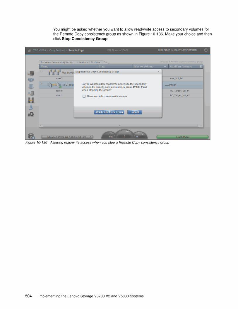
You might be asked whether you want to allow read/write access to secondary volumes for the Remote Copy consistency group as shown in Figure 10-136. Make your choice and then click Stop Consistency Group.
Figure 10-136 Allowing read/write access when you stop a Remote Copy consistency group
504 Implementing the Lenovo Storage V3700 V2 and V5030 Systems

The consistency group is in the Consistent Stopped state if you chose not to allow read/write access, or the consistency group is in the Idling state if you chose to allow read/write access, as shown in Figure 10-137.
Starting a consistency groupYou can start a consistency group by clicking Start in the Actions drop-down menu, as shown in Figure 10-137, or by right-clicking the consistency group and clicking Start.
Figure 10-137 Starting the consistency group
Note: The CLI differentiates between stopping consistency groups with or without read/write access by using the -access flag, for example, stoprcconsistgrp -access 0.
Chapter 10. Copy services 505

You are prompted to select whether the master volumes or auxiliary volumes act as the primary volumes before the consistency group is started, as shown in Figure 10-138. The consistency group can then copy data from the primary volumes to the secondary volumes. If the consistency group was stopped without access and if it is in the Consistent Stopped state, you are prompted to confirm the direction in which to start the group. The group can start, by default, by using the original primary volumes from when it was stopped.
Figure 10-138 Confirming the replication direction
Important: If you are starting a consistency group where access was previously allowed to auxiliary volumes when the group was stopped, ensure that you choose the correct volumes to act as the primary volumes when you restart. Choosing the wrong volumes can lead to data loss.
506 Implementing the Lenovo Storage V3700 V2 and V5030 Systems

Switching a consistency groupAs with the switch action on the Remote Copy relationship, you can switch the copy direction of the consistency group. To switch the copy direction of the consistency group, highlight the consistency group and click Switch from the Actions drop-down menu, as shown in Figure 10-139.
Figure 10-139 Switch the copy direction of a consistency group
A warning message appears, as shown in Figure 10-140. After the switch, the primary volumes in the consistency group change. Write access to current master volumes is lost, while write access to the current auxiliary volumes is enabled. This change affects host access, so ensure that these settings are correct, and if so, click Yes.
Figure 10-140 Warning message to confirm the switch
Chapter 10. Copy services 507

This option is used for disaster recovery and disaster recovery testing. Ensure that host access to the primary volumes is stopped before you switch. You can then mount hosts on the auxiliary volumes and continue production from a DR site. As before, with individual Remote Copy relationships, all of the relationships that switched as part of the consistency group now show an icon that indicates that they changed direction. This icon is shown in Figure 10-141.
Figure 10-141 Consistency group after the roles switch
508 Implementing the Lenovo Storage V3700 V2 and V5030 Systems

Removing Remote Copy relationships from a consistency groupRemote Copy relationships can be removed from a consistency group by selecting the Remote Copy relationship and by clicking Remove from Consistency Group from the Actions drop-down menu, as shown in Figure 10-142. Alternatively, right-click the Remote Copy relationship that you want to remove and click Remove from Consistency Group.
Figure 10-142 Remove a Remote Copy relationship from a consistency group
A warning appears, as shown in Figure 10-143. Ensure that the Remote Copy relationship that is shown in the window is the Remote Copy relationship that you want to remove from the consistency group. Click Remove.
Figure 10-143 Confirm the Remote Copy relationship to remove from the consistency group
Chapter 10. Copy services 509

After the removal process completes, the Remote Copy relationship is deleted from the consistency group and displayed in the Not in a Group list, as shown in Figure 10-144.
Deleting a consistency groupThe consistency group can be deleted by clicking it and selecting Delete from the Actions drop-down menu, as shown in Figure 10-144. Alternatively, right-click the consistency group that you want to delete and click Delete.
Figure 10-144 Delete a consistency group
You must confirm the deletion of the consistency group, as shown in Figure 10-145. Click Yes if you are sure that you want to delete this consistency group.
Figure 10-145 Warning to confirm the deletion of the consistency group
510 Implementing the Lenovo Storage V3700 V2 and V5030 Systems

The consistency group can be deleted. Any relationships that were part of it are returned to the Not in a Group list, as shown in Figure 10-146.
Figure 10-146 Remote Copy relationships that return to the Not in a Group list after the consistency group deletion
10.5 HyperSwap
The HyperSwap high availability function allows business continuity in a hardware failure, power failure, connectivity failure, or disasters, such as fire or flooding. It is available on the IBM Storwize V7000 for Lenovo, IBM Storwize V5000 for Lenovo products, and Lenovo Storage V series products.
The HyperSwap function provides highly available volumes that are accessible through two sites at up to 300 km (186.4 miles) apart. A fully independent copy of the data is maintained at each site. When data is written by hosts at either site, both copies are synchronously updated before the write operation is completed. The HyperSwap function automatically optimizes itself to minimize data that is transmitted between sites and to minimize host read and write latency.
If the nodes go offline or the storage at either site goes offline, leaving an online and accessible up-to-date copy, the HyperSwap function can automatically fail over access to the online copy. The HyperSwap function also automatically resynchronizes the two copies when possible.
HyperSwap capability enables each volume to be presented by two I/O groups. The configuration tolerates combinations of node and site failures, by using the same flexible choices of host multipathing driver interoperability that are available for the IBM Storwize for Lenovo products. The use of FlashCopy helps maintain a golden image during automatic resynchronization.
Important: Because Remote Mirroring is used to support the HyperSwap capability, Remote Mirroring licensing is a requirement for using HyperSwap.
Chapter 10. Copy services 511

The HyperSwap function uses a hyperswap topology by spreading the control enclosure of the system across two sites, with storage at a third site that acts as a tie-breaking quorum device:
� The HyperSwap topology requires at least one control enclosure in each main data site. Therefore, to get a volume that is resiliently stored on both sites, one control enclosure with the necessary storage capacity is required.
� The HyperSwap topology uses additional system resources to support a fully independent cache on each site, providing full performance even if one site is lost. In certain environments, a hyperswap topology provides better performance than a stretched topology.
� The HyperSwap function can be configured by using the command-line interface (CLI). The HyperSwap function also adds the ability to configure and manage local HyperSwap through the GUI for simpler configuration and operation.
� The hosts, Lenovo Storage V3700 V2, V3700 V2 XP and V5030 control enclosures, and Lenovo Storage V3700 V2, V3700 V2 XP and V5030 storage enclosures are in one of two failure domains or sites. External virtualized storage capacity can also be used.
� Volumes are visible as a single object across both sites (the Lenovo Storage V3700 V2, V3700 V2 XP and V5030 control enclosure).
At least two control enclosures are required for HyperSwap. System scalability depends on the hardware details, as shown in Table 10-6.
Table 10-6 HyperSwap support
So, a Lenovo Storage V series HyperSwap cluster is always restricted to a single control enclosure per site. The Storwize V7000 for Lenovo can provide more scalability and offer more flexibility.
10.5.1 Introduction to HyperSwap volumes
The HyperSwap function is built on the Remote Copy features that include Metro Mirror, Global Mirror, and Global Mirror with Change Volumes.
The HyperSwap function works with the standard multipathing drivers that are available on various host types. No additional host support is required to access the highly available volume. Where multipathing drivers support Asymmetric Logical Unit Access (ALUA), the storage system informs the multipathing driver about the nodes that are in the same site and the nodes that need to be used to minimize I/O latency.
The host and Storwize V5000 for Lenovo site attributes must be configured to enable this optimization and to enable HyperSwap functionality. A three-site setup is required. Two sites are used as the main data center to provide two independent data copies. A quorum disk or an IP-based quorum can be used as a quorum device. However, the quorum device must be placed in a third, independent site.
V3700 V2
V3700 V2 XP
V5030 V5000 G1 V7000
Maximum number of I/O groups 1 1 2 2 4
Support for HyperSwap No No Yes Yes Yes
Support for Stretched Cluster No No No No No
512 Implementing the Lenovo Storage V3700 V2 and V5030 Systems

The quorum disk must be supported as an “extended quorum device”. The connection can be implemented by using Fibre Channel, Fibre Channel through wavelength-division multiplexing (WDM), synchronous digital hierarchy (SDH) and synchronous optical network (SONET), or FCIP. The minimum bandwidth is 2 MBps.
The IP quorum substitutes the active quorum disk’s tiebreaker role. Redundancy can be implemented by using multiple quorum apps, similar to multiple quorum disks. However, only one app is active at a time. The other apps are available if the active quorum device app fails. For more information about quorum devices, see the Lenovo V3700V2/V5030 information Center:
http://systemx.lenovofiles.com/mobile/help/topic/com.lenovo.storage.v3700.doc/lenovo_vseries.html
Because HyperSwap is running as a single cluster that is distributed across two main data centers, one Lenovo Storage V3700 V2, V3700 V2 XP and V5030 control enclosure is required in each site. Both control enclosures must be added to the same cluster. Only the Lenovo Storage V5030 supports the clustering of two control enclosures, so two Lenovo Storage V5030 control enclosures are required for HyperSwap. Metro Mirror is used to keep both data copies in sync.
Chapter 10. Copy services 513

The host accesses both I/O groups, as shown in Figure 10-147. The original Metro Mirror target ID is not used for host access. Instead, HyperSwap presents the Metro Mirror source ID for the target volume to the host. From the host perspective, the same volume is available on both I/O groups, although the Lenovo Storage V3700 V2, V3700 V2 XP and V5030 volumes are connected through Metro Mirror.
Figure 10-147 HyperSwap
514 Implementing the Lenovo Storage V3700 V2 and V5030 Systems

A site attribute must be set for any host, Lenovo Storage V3700 V2, V3700 V2 XP and V5030 storage systems, and external virtualized storage system. The host uses the local I/O group (same site attribute) for data access, as shown in Figure 10-148.
The continuous blue line shows the host default access path to the volume at the same site. The dotted blue line shows the non-preferred access path that is used if the preferred access path is not available. Accessing both I/O groups doubles the number of paths from host to volume. Take note of the limited number of supported paths for your multipath device driver and limit the number of paths to an acceptable level.
Figure 10-148 Data access
Chapter 10. Copy services 515

Data flowThe host reads and writes data to the local I/O group within the same site. The HyperSwap system sends the data to the remote site by using internal Metro Mirror, as shown in Figure 10-149.
Figure 10-149 Data flow for a single volume
If a host accesses the volume on the Metro Mirror target site, all read and write requests can be forwarded to the I/O group that acts as the Metro Mirror source volume, as shown in Figure 10-150 on page 517. All host-related traffic must be handled from the remote I/O group, which increases the long-distance data traffic.
516 Implementing the Lenovo Storage V3700 V2 and V5030 Systems

Figure 10-150 Data flow from the “wrong” site
Chapter 10. Copy services 517

Access to the Metro Mirror target volume is measured and HyperSwap triggers a switch of the Metro Mirror copy direction, if the workload on the “wrong” site is significantly higher than the workload on the Metro Mirror source site over any length of time, as shown in Figure 10-151. This copy direction switch reduces the additional host-related long-distance traffic and provides better response time.
Figure 10-151 Data flow: Switch copy direction
The duration until the copy direction switches depends on the load distribution on the volume in both sites. Although a HyperSwap volume can be accessed concurrently for read and write I/O from any host in any site, all I/O is forwarded to one I/O group in one site. Usage of the wrong site increases the long-distance traffic. The HyperSwap cluster monitors the workload and it can switch the copy direction if the highest workload is arriving on the wrong site.
Applications with an equal workload pattern to the same volume by using both I/O groups (Oracle Real Application Clusters (RAC) and VMware vMotion) are not optimal for local HyperSwap.
518 Implementing the Lenovo Storage V3700 V2 and V5030 Systems

10.5.2 Failure scenarios
If one node fails, the other node in the same I/O group takes over the responsibility for all volumes that are owned by the affected I/O group, as shown in Figure 10-152. The system can deactivate the write cache, which might influence the overall performance. The multipath driver can switch the active paths to the named node. The Metro Mirror relationship continues to operate and provides a synchronous, consistent copy at the remote I/O group.
Figure 10-152 Single node failure in an I/O group
Chapter 10. Copy services 519

If an I/O group fails, the host can use the second I/O group at the remote site, as shown in Figure 10-153. The remote I/O group handles all volume-related traffic, but HyperSwap cannot keep both copies in sync anymore because of an inactive I/O group.
Figure 10-153 I/O group failure
520 Implementing the Lenovo Storage V3700 V2 and V5030 Systems

As soon as the failed I/O group is back, the system can automatically resynchronize both copies in the background. Before the resynchronization, the Lenovo Storage V3700 V2, V3700 V2 XP and V5030 can perform a FlashCopy on HyperSwap source and target volumes, as shown in Figure 10-154. Each change volume requires two FlashCopy relationships, one relationship in each direction. So, four FlashCopy relationships are required for each HyperSwap volume.
To provide an easy to use GUI, those relationships and FlashCopy volumes are not shown in the GUI. They are visible and manageable by using the CLI.
Figure 10-154 Resynchronization
Chapter 10. Copy services 521

After successful resynchronization, the host switches automatically to the I/O group at the same site for the best performance and limited inter-switch link (ISL) usage, as shown in Figure 10-155.
Figure 10-155 Data flow after resynchronization
HyperSwap uses Metro Mirror technology, which enables the usage of Metro Mirror consistency groups that are described in “Remote Copy consistency groups” on page 464.
10.5.3 Current HyperSwap limitations
HyperSwap has the following limitations:
� Cluster internal Metro Mirror is used for replication, so the size of a HyperSwap volume cannot be changed by using expandvdisksize and shrinkvdisksize.
� A cascaded Remote Copy is not available. HyperSwap volumes cannot be replicated to a second, independent storage system by using Remote Copy functionality.
522 Implementing the Lenovo Storage V3700 V2 and V5030 Systems

� Four FlashCopy mappings are required for each HyperSwap volume, which limits the number of HyperSwap volumes to 1,024. Additional FlashCopy requirements can reduce the number of possible HyperSwap volumes.
� Hosts that access a HyperSwap volume through Internet Small Computer System Interface (iSCSI) or serial-attached SCSI (SAS) cannot take advantage of the high availability function.
� FlashCopy usage can be complicated because the Metro Mirror source volume and target volume can switch during daily operation. Because of this possibility, the identification of the copy direction is required for a successful FlashCopy.
� The Remote Copy relationship must be removed first for a reverse FlashCopy operation. After a reverse FlashCopy, all HyperSwap functions must be implemented manually again (Remote Mirror + FlashCopy relationships).
� IBM FlashCopy Manager is not supported by HyperSwap volumes.
10.5.4 Configuring HyperSwap
Two independent Storwize V5000 for Lenovo control enclosures (IO groups) are required, both of which are placed in one main site. Those control enclosures must be configured together in a single Storwize cluster. Appropriate Fibre Channel or Fibre Channel over Ethernet (FCoE) connections are required between both sites.
Two main storage area network (SAN) configuration options are available:
� Configuration with inter-switch links (ISLs) between both sites� Configuration without ISLs between both sites
For more information about the requirements and use cases that are available at the Information Center, select Lenovo Storage V3700 V2/V5030 Series → Configuring → Configuration details → HyperSwap system configuration details at the following website:
http://systemx.lenovofiles.com/mobile/help/topic/com.lenovo.storage.v3700.doc/svc_hyperswap_configuration.html
In a configuration with ISLs between both sites, a division of the SAN infrastructure in a public SAN and a private SAN is required. For more information, see Lenovo Storage V3700 V2/V5030 Series → Configuring → Configuration details → HyperSwap system configuration details at the Information Center:
http://systemx.lenovofiles.com/mobile/help/topic/com.lenovo.storage.v3700.doc/svc_quorumoverview.html
A quorum device in a third, independent site is required. For more information, select Lenovo Storage V3700 V2/V5030 Series → Configuring → Configuration details → Quorum at the Information Center:
http://systemx.lenovofiles.com/mobile/help/topic/com.lenovo.storage.v3700.doc/svc_quorumoverview.html
Connection between both main sitesMetro Mirror is used for HyperSwap, so the Metro Mirror bandwidth requirements are the minimum requirements for HyperSwap. The total required bandwidth between both sites depends on the SAN configuration (with or without ISL), the host peak workload, and the expected growth rate.
Chapter 10. Copy services 523

Configuration with ISLA bandwidth that is equal to the peak write bandwidth (as the sum from all hosts) is required for intersite communication between I/O groups. This bandwidth must be available in the private SAN. Additionally, you need intersite bandwidth in the public SAN for host-to-node read and write communication if a host accesses nodes in the other sites, for example, after a failure of the local I/O group of the host or to access volumes that do not use the HyperSwap function.
The guideline for a bandwidth that is equal to the peak write bandwidth for private SANs provides the minimal bandwidth that is supported for HyperSwap operations. In certain non-optimal configurations, additional bandwidth is required to avoid potential performance issues. For example, if hosts at different sites share a volume, the private SAN needs bandwidth that is equal to two times the peak write bandwidth, plus the peak read bandwidth. Additional bandwidth is required for initial synchronization or resynchronization.
Therefore, the total required bandwidth can be calculated in the following way:
� For a public SAN:
Peak host read and write throughput + expected growth
� For a private SAN:
Peak host write throughput + surcharge for volumes that are used from hosts in both sites + bandwidth for initial synchronization and resynchronization + expected growth rate
However, in any case, at least 4 Gbps are required in the private SAN if the calculated bandwidth is under 4 Gbps.
The following example shows how to calculate the total required bandwidth with ISLs:
� In our example, we know that the total host peak throughput is 30 GBps and 10 GBps is the approximate write throughput.
� We assume that 20% of the peak host workload is created on volumes that are accessed from hosts at both sites, such as in an Oracle RAC environment.
� We add 20% for initial synchronization and resynchronization.
� The expected growth is 50% in 3 years.
The simplified bandwidth calculation can be performed in the following ways.
524 Implementing the Lenovo Storage V3700 V2 and V5030 Systems

Table 10-7 shows a calculation for a public SAN.
Table 10-7 Public SAN calculation
Table 10-8 shows a calculation for a private SAN.
Table 10-8 Private SAN calculation
So, at least 45 GBps throughput is required for the public SAN, and 19.5 GBps throughput is required for the private SAN.
Configuration without ISLThe required bandwidth in a configuration without ISL is significantly lower compared to a configuration with ISL because the V5000 must not hold bandwidth in different SANs. We use the same example that we described in “Configuration with ISL” on page 524.
The following example shows how to calculate the total required bandwidth without ISLs:
� In our example, we know that the total host peak throughput is 30 GBps, and 10 GBps is the approximate write throughput.
� We assume that 20% of the peak host workload is created on volumes that are accessed from hosts at both sites, such as in an Oracle RAC environment.
� We add 20% for initial synchronization and resynchronization.
� The expected growth is 50% in 3 years.
Public SAN Input Formula Result
Total host peak read and write throughput 30 GBps N/A 30 GBps
Expected growth 50% 50% of 30 GBps 15 GBps
Total Public SAN bandwidth 30 GBps + 15 GBps 45 GBps
Private SAN Input Formula Result
Peak host write throughput 10 GBps N/A 10 GBps
Volumes that are used from hosts in both sites
20%, but half of them use the wrong site, so effectively 10%
10% of 10 GBps 1 GBps
Synchronization 20% 20% of 10 GBps 2 GBps
Subtotal 10 GBps + 1 GBps + 2 GBps 13 GBps
Expected growth 50% 50% of 13 GBps 6.5 GBps
Total private SAN bandwidth
13 GBps + 6.5 GBps 19.5 GBps
Chapter 10. Copy services 525

Table 10-9 shows the simplified bandwidth calculation.
Table 10-9 Simplified bandwidth calculation
At least 49.5 GBps throughput is required in a configuration without ISL.
SAN designA redundant design is recommended with two independent physical links between both sites. Each link must be able to handle the calculated workload separately.
The following configuration steps are required:
1. Configure a single Storwize V5000 for Lenovo cluster by using at least two Storwize V5000 for Lenovo control enclosures.
2. Set the site attributes for the hosts, Storwize V5000 for Lenovo control enclosures, and external storage.
3. Define the quorum device.
4. Implement the internal Metro Mirror partnership.
5. Set the cluster to HyperSwap.
6. Define the HyperSwap volumes.
7. Assign the HyperSwap volumes to the host.
Configure a cluster with more than one I/O groupA cluster with two I/O groups (control enclosures) is required. HyperSwap support is available for the Lenovo Storage V5030. However, clustering of multiple control enclosures is not supported by the Lenovo Storage V3700 V2 or Lenovo Storage V3700 V2 XP.
Set site attributesTo configure a HyperSwap system topology, you set the site attributes for nodes, external storage systems, and hosts by using the CLI.
Meaningful site names are helpful for easier management of the HyperSwap topology.
Input Formula Result
Peak host read and write throughput
30 GBps N/A 30 GBps
Peak host write throughput
10 GBps N/A N/A
Volumes that are used from hosts in both sites
20%, but half of them use the wrong site, so effectively 10%
10% of 10 GBps 1 GBps
Synchronization 20% 20% of 10 GBps 2 GBps
Subtotal 30 GBps + 1 GBps + 2 GBps 33 GBps
Expected growth 50% 50% of 33 GBps 16.5 GBps
Total private SAN bandwidth
33 GBps + 16.5 GBps 49.5 GBps
526 Implementing the Lenovo Storage V3700 V2 and V5030 Systems

Initially, we change the site names to DC_1 and DC_2 (DataCenter 1 and DataCenter 2) and DC_Quorum, as shown in Example 10-1.
Example 10-1 Change site name
IBM_Storwize:V5000_2021:superuser>lssiteid site_name1 site12 site23 site3IBM_Storwize:V5000_2021:superuser>svctask chsite -name DC_1 1IBM_Storwize:V5000_2021:superuser>svctask chsite -name DC_2 2IBM_Storwize:V5000_2021:superuser>svctask chsite -name DC_Quorum 3IBM_Storwize:V5000_2021:superuser>lssiteid site_name1 DC_12 DC_23 DC_QuorumIBM_Storwize:V5000_2021:superuser>
The site attributes for storage nodes must be configured, as shown in Example 10-2.
Example 10-2 Set the site attributes for the Storwize V5000 for Lenovo storage nodes
IBM_Storwize:V5000_2021:superuser>svcinfo lsnode...1 node1 ... online 0 V5000_20 ...2 node2 ... online 0 V5000_20 ...5 node3 ... online 1 V5000_21 ...6 node4 ... online 1 V5000_21 ...IBM_Storwize:V5000_2021:superuser>IBM_Storwize:V5000_2021:superuser>svctask chnodecanister -site DC_1 node1IBM_Storwize:V5000_2021:superuser>svctask chnodecanister -site DC_1 node2IBM_Storwize:V5000_2021:superuser>svctask chnodecanister -site DC_2 node3IBM_Storwize:V5000_2021:superuser>svctask chnodecanister -site DC_2 node4IBM_Storwize:V5000_2021:superuser>IBM_Storwize:V5000_2021:superuser>svcinfo lsnode...1 node1 ... online 0 V5000_20 ... 1 DC_12 node2 ... online 0 V5000_20 ... 1 DC_15 node3 ... online 1 V5000_21 ... 2 DC_26 node4 ... online 1 V5000_21 ... 2 DC_2IBM_Storwize:V5000_2021:superuser>
The site attributes for external virtualized storage must be configured, as shown in Example 10-3. A site must be assigned to all storage systems that are attached to the HyperSwap cluster in the future.
Example 10-3 Set the site attributes for the external virtualized storage
IBM_Storwize:V5000_2021:superuser>lscontroller0 V3700_04_C1 2076 IBM 21451 V3700_04_C2 2076 IBM 21452 V3700_06_C1 2076 IBM 21453 V3700_06_C2 2076 IBM 2145IBM_Storwize:V5000_2021:superuser>chcontroller -site DC_1 0IBM_Storwize:V5000_2021:superuser>chcontroller -site DC_1 1
Chapter 10. Copy services 527

IBM_Storwize:V5000_2021:superuser>chcontroller -site DC_2 2IBM_Storwize:V5000_2021:superuser>chcontroller -site DC_2 3IBM_Storwize:V5000_2021:superuser>CHECK CONTROLLER OUTPUT IN AN OTHER ENVIRONMENT!!!!!
The site attributes for hosts must be set as shown in Example 10-4. The site attribute must be assigned to all hosts that are attached to the HyperSwap cluster in the future.
Example 10-4 Set the host site attributes
IBM_Storwize:V5000_2021:superuser>lshostid name port_count iogrp_count status site_id site_name0 ESX_01 1 1 online1 ESX_02 1 1 online 2 Win2008_1 1 1 onlineIBM_Storwize:V5000_2021:superuser>IBM_Storwize:V5000_2021:superuser>chhost -site DC_1 ESX_01IBM_Storwize:V5000_2021:superuser>chhost -site DC_2 ESX_02IBM_Storwize:V5000_2021:superuser>chhost -site DC_1 Win2008_1IBM_Storwize:V5000_2021:superuser>lshostid name port_count iogrp_count status site_id site_name0 ESX_01 1 1 online 1 DC_11 ESX_02 1 1 online 2 DC_22 Win2008_1 1 1 online 1 DC_1IBM_Storwize:V5000_2021:superuser>
A detailed description of setting the site attributes is available at the Information Center:
http://systemx.lenovofiles.com/mobile/help/topic/com.lenovo.storage.v3700.doc/svc_config_hyperswap_sites.html
Define the quorum deviceThe quorum device can be implemented by using an external storage system, which must be assigned to the third site. Alternatively, an IP quorum application can be used to provide the quorum. To assign an external storage system to the third site, use the commands that are shown in Example 10-5.
Example 10-5 Set the site attribute for the external storage controller
IBM_Storwize:V5000_2021:superuser>lscontroller...4 V3700_08_C1 2076 IBM 21455 V3700_08_C2 2076 IBM 2145IBM_Storwize:V5000_2021:superuser>IBM_Storwize:V5000_2021:superuser>chcontroller -site DC_quorum V3700_08_C1IBM_Storwize:V5000_2021:superuser>chcontroller -site DC_quorum V3700_08_C2
The HyperSwap environment requires an active quorum disk in site 3 and one quorum disk candidate in the other two main sites. The storage system V3700_08 is located in the third site and one managed disk (mdisk3) is used as the active quorum disk. The storage system disk drives are used in DC_1 and DC_2 as quorum disk candidates.
528 Implementing the Lenovo Storage V3700 V2 and V5030 Systems

The cluster must not be able to change the quorum disk settings, so the “override yes” flag must be set, as shown in Example 10-6.
Example 10-6 Set the active quorum disk
IBM_Storwize:V5000_2021:superuser>lsquorum...0 online 23 no drive no 2 DC_21 online 11 no drive no 1 DC_12 online 3 mdisk3 V3700_08 no mdisk no 3 DC_quorumIBM_Storwize:V5000_2021:superuser> chquorum -drive 23 -override yes 0IBM_Storwize:V5000_2021:superuser> chquorum -drive 11 -override yes 1IBM_Storwize:V5000_2021:superuser> chquorum -active -mdisk mdisk3 -override yes 2IBM_Storwize:V5000_2021:superuser>lsquorum...0 online 23 no drive yes 2 DC_21 online 11 no drive yes 1 DC_12 online 3 mdisk3 V3700_08 yes mdisk yes 3 DC_quorum
Set the cluster to HyperSwapThe storage systems must be set to HyperSwap mode, as shown in Example 10-7.
Example 10-7 Set the storage systems to HyperSwap mode
IBM_Storwize:V5000_2021:superuser>chsystem -topology hyperswapIBM_Storwize:V5000_2021:superuser>lssystem | grep topologytopology hyperswap
HyperSwap is now active. The GUI provides more HyperSwap capabilities, for example, during the volume creation process. The pools are automatically assigned to the correct site and the GUI offers easy management.
Chapter 10. Copy services 529

Configure HyperSwap volumesThe GUI offers an easy-to-use management interface during the HyperSwap volume creation process. Click Create Volumes, which is available when you click Volumes → Volumes, as shown in Figure 10-156.
Figure 10-156 Create volumes
A wizard provides multiple options, as shown in Figure 10-157:
� Quick Volume Creation option for basic volumes
� Quick Volume Creation option for HyperSwap volumes (which is used for easy configuration)
� Advanced volume creation option, which is available for all volumes with many customizable options
Figure 10-157 Select volume creation wizard
530 Implementing the Lenovo Storage V3700 V2 and V5030 Systems

Selecting the HyperSwap wizard guides you through an easy-to-use volume creation process, as shown in Figure 10-158. You must set the volume capacity, the volume name, and the pools in each site. Additional functions, such as thin provisioning and compression, are optional settings. You can modify I/O group-related settings.
Figure 10-158 Quick HyperSwap volume creation
Chapter 10. Copy services 531
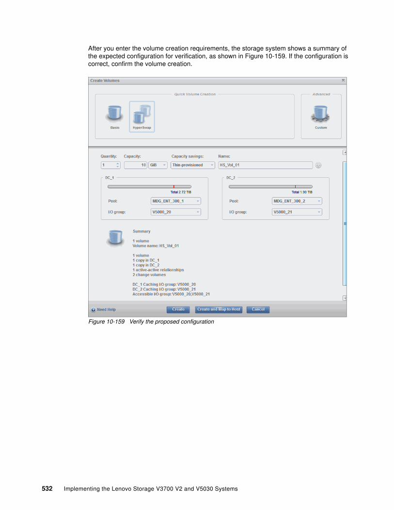
After you enter the volume creation requirements, the storage system shows a summary of the expected configuration for verification, as shown in Figure 10-159. If the configuration is correct, confirm the volume creation.
Figure 10-159 Verify the proposed configuration
532 Implementing the Lenovo Storage V3700 V2 and V5030 Systems

The new HyperSwap volume is visible in the GUI by selecting Volumes → Volumes, as shown in Figure 10-160. Only HyperSwap master and auxiliary volumes are shown in the GUI. The required Flash Copy volumes are hidden to reduce the level of complexity.
Figure 10-160 GUI: HyperSwap volume
All associated volumes (master, auxiliary, and change volumes) are visible by using the CLI, as shown in Figure 10-161. For better readability, the CLI output was reduced in the following examples.
Figure 10-161 Four volumes are related to a single HyperSwap volume (simplified)
Also, the system creates four FlashCopy mappings for each HyperSwap volume, as shown in Figure 10-162.
Figure 10-162 Four FlashCopy mappings relate to a single HyperSwap volume (simplified)
IBM_Storwize:V5000_2021:superuser>lsvdisk...0 HS_Vol_01 0 V5000_20 online 0 MDG_ENT_300_1 10.00GB ... rcrel0 HS_Vol_01 master1 vdisk1 1 V5000_21 offline 3 MDG_ENT_300_2 10.00GB ... rcrel0 HS_Vol_01 aux2 vdisk2 0 V5000_20 online 0 MDG_ENT_300_1 10.00GB ... rcrel0 HS_Vol_01 master_change3 vdisk3 1 V5000_21 online 3 MDG_ENT_300_2 10.00GB ... rcrel0 HS_Vol_01 aux_changeIBM_Storwize:V5000_2021:superuser>
IBM_Storwize:V5000_2021:superuser>lsfcmap... 0 fcmap1 0 HS_Vol_01 2 vdisk2 idle_or_copied 0 1 fcmap0 2 vdisk2 0 HS_Vol_01 idle_or_copied 0 2 fcmap2 1 vdisk1 3 vdisk3 idle_or_copied 0 3 fcmap3 3 vdisk3 1 vdisk1 idle_or_copied 0 IBM_Storwize:V5000_2021:superuser>
Chapter 10. Copy services 533

Create hosts for the HyperSwap volumesYou can create a host by clicking Hosts → Hosts and by selecting Add host. The Add Host window opens, as shown in Figure 10-163. You must select the correct host site attributes during the configuration process.
Figure 10-163 Create the host and set the site attributes
Setting the wrong site attributes can cause additional long-distance traffic to the remote I/O group instead of using the local access capabilities. You can modify the I/O groups that need to provide access to the HyperSwap volume, as shown in Figure 10-164. You are required to set the host access to each I/O group in each site.
Figure 10-164 Set the I/O group access for each host
534 Implementing the Lenovo Storage V3700 V2 and V5030 Systems

The new host is visible in the GUI by clicking Hosts → Hosts, as shown in Figure 10-165. To switch the host site attribute, click Modify Site from the Actions drop-down menu, as shown in Figure 10-165, and follow the wizard.
Figure 10-165 Modify the host site
You can modify or change the host settings by using the CLI. Example 10-8 shows the site settings for two servers.
Example 10-8 Host site settings
IBM_Storwize:V5000_2021:superuser>lshostid name port_count iogrp_count status site_id site_name0 Server_01 1 4 online 1 DC_11 Server_02 1 4 online 2 DC_2IBM_Storwize:V5000_2021:superuser>
Chapter 10. Copy services 535

Assign HyperSwap volumes to hostsYou can assign the HyperSwap volume in the GUI by selecting Volumes → Volumes and then by clicking Map to Host in the Actions menu, as shown in Figure 10-166.
Figure 10-166 Map HyperSwap volumes to hosts
The host must be selected during the volume assignment, and the attribute that was defined must be visible, as shown in Figure 10-167.
Figure 10-167 Select hosts for volume assignment
536 Implementing the Lenovo Storage V3700 V2 and V5030 Systems

After you select Volumes → Volumes, you can unassign the volume by clicking Unmap all Hosts in the Actions menu, as shown in Figure 10-168.
Figure 10-168 Unmap all hosts from a volume
After you select Hosts → Hosts, you can change the volume mapping by clicking Modify Volume Mappings on the Actions menu, as shown in Figure 10-169.
Figure 10-169 Modify volume mappings to hosts
Chapter 10. Copy services 537

In the new wizard, you can change all volume mappings for any host and any volume, as shown in Figure 10-170.
Figure 10-170 Change volume mapping
10.5.5 Consistency groups for HyperSwap volumes
A consistency group is a logical entity that groups copy relationships. By grouping the relationships, you can ensure that these relationships are managed in unison and the data within the group is in a consistent state.
Remote Copy commands can be issued to a consistency group and simultaneously for all Metro Mirror relationships that are defined within that consistency group, or to a single Metro Mirror relationship that is not part of a Metro Mirror consistency group. For more information about consistency groups, see “Remote Copy consistency groups” on page 464.
HyperSwap uses Remote Mirror functionality, so consistency groups are available for HyperSwap volumes. However, not all consistency group features are usable in a HyperSwap environment. HyperSwap relationships always restart and resync automatically, so in contrast to a standard Metro Mirror, a HyperSwap relationship cannot be started or stopped manually. Changing the copy direction is an automated process.
538 Implementing the Lenovo Storage V3700 V2 and V5030 Systems

Those functions are not available for HyperSwap consistency groups, as shown in Figure 10-171. The copy direction is the same for all volumes within the consistency group. The copy direction optimization is based on consistency groups instead of volume relationships. Therefore, a consistency group that is built out of multiple HyperSwap volumes with workload on different sites is not optimal and increases the long-distance traffic.
Figure 10-171 Available options for HyperSwap
Chapter 10. Copy services 539

HyperSwap volume assignment to consistency groupsAfter you select Copy Services → Remote Copy, you can create a consistency group by clicking Create Consistency Group, as shown in Figure 10-172.
Figure 10-172 Create consistency group
The wizard guides you through the steps. The auxiliary volumes are on the same system, so select the appropriate option and create an empty consistency group. Select the Remote Copy relationship that you want to move to the consistency group and click Actions → Add to Consistency Group, as shown in Figure 10-173.
Figure 10-173 Add a Remote Copy relationship to a consistency group
540 Implementing the Lenovo Storage V3700 V2 and V5030 Systems

To assign other relationships to the same consistency group, perform the same steps again. The number of available options for a HyperSwap consistency group is limited, as shown Figure 10-174.
Figure 10-174 HyperSwap consistency group options
More details about consistency groups and how to use them were described in “Remote Copy consistency groups” on page 464, but a few small differences exist in the failure scenarios.
Chapter 10. Copy services 541

Example for a consistency group failureIn our example, we created a HyperSwap consistency group and assigned three HyperSwap volumes, as shown in Figure 10-175. The consistency group status and the volume relationship status are identical: Consistent_Synchronized.
Figure 10-175 Consistency group with HyperSwap volumes
One HyperSwap target volume in the group was a thin-provisioned volume. The capacity of the pool was insufficient to fulfill all capacity requirements. At a certain point, the capacity was insufficient on the target volume, and the storage system set the target volume offline, as shown in Figure 10-176.
Figure 10-176 Disk failure in a HyperSwap
542 Implementing the Lenovo Storage V3700 V2 and V5030 Systems

The system created entries in the event log, as shown in Figure 10-177.
Figure 10-177 Error message because of disk failure
The consistency group and the volume relationship status changed to Consistent_Copying (marked in blue), as shown in Figure 10-178. The storage system creates an additional FlashCopy for each volume in the consistency group. The freeze time is marked in red. The source volume is still accessible.
Figure 10-178 Status of the consistency group and the volume relationships after a failure
The resynchronization starts as soon as the problems (in this case, insufficient capacity) are resolved.
10.5.6 FlashCopy operations and HyperSwap volumes
The design and usage of FlashCopy were described in 10.1, “FlashCopy” on page 394. FlashCopy usage with HyperSwap volumes is possible but limitations exist.
HyperSwap volumes are based on the Metro Mirror relationship. They automatically switch copy direction, depending on workload distribution and external events, such as a connection loss between both sites. Because of this capability, both master and auxiliary volumes can be a Remote Copy source volume or target volume, which might affect the FlashCopy operation:
� A Remote Copy target volume can be out of date, so the Remote Copy source volume needs to be used for FlashCopy operation.
� A volume in a Remote Copy relationship cannot be used as a FlashCopy target volume.
� The Remote Copy target volume is shown as offline in a HyperSwap relationship.
Up-front preparation for FlashCopy operations is required because of the limitations. The Remote Copy source must be used for FlashCopy. Therefore, it must first be identified before a FlashCopy operation is performed.
Chapter 10. Copy services 543

The copy direction of a Remote Copy relationship is visible in Copy Services → Remote Copy, as shown in Figure 10-179. In our example, two HyperSwap volumes are defined. Each HyperSwap volume is defined by its own relationship. Master and auxiliary volumes are defined for each relationship.
Figure 10-179 HyperSwap Remote Copy relationships
Because HyperSwap is an Active Active copy type, the copy direction is independent from the master and auxiliary definition. You can identify the copy direction by using the small, highlighted (in red) symbol in the State column, as shown in Figure 10-180.
Two options are available:
� No small symbol shows in the State field of a relationship: The master volume is used as the Remote Copy source volume. Therefore, for relationship rcrel0, volume HS_Vol_01 in DC_1 (marked in blue) is used as a Remote Copy source volume.
� A small symbol shows in the State field of a relationship: The auxiliary volume is used as the Remote Copy source volume. Therefore, for relationship rcrel1, volume HS_Vol_02 in DC_2 (marked in blue) is used as a Remote Copy source volume.
Figure 10-180 HyperSwap copy direction identification
544 Implementing the Lenovo Storage V3700 V2 and V5030 Systems

You can use the CLI for replication direction identification. Figure 10-181 shows the simplified CLI output of the two HyperSwap relationships that were previously described. The primary field shows the volume (master or aux, which are marked in Figure 10-181 in bold) that is used as the Remote Copy source volume.
Figure 10-181 Identification of the HyperSwap copy direction by using CLI
Those source volumes (marked in blue) are candidates for FlashCopy activities (marked in red), as shown in Figure 10-182. The named FlashCopy options were described in 10.1, “FlashCopy” on page 394.
Figure 10-182 FlashCopy options that are available for HyperSwap volumes
IBM_Storwize:V5000_2021:superuser>lsrcrelationship...0 rcrel0 ... V5000_2021 0 HS_Vol_01 V5000_2021 1 vdisk1 master ...4 rcrel1 ... V5000_2021 4 HS_Vol_02 V5000_2021 5 vdisk4 aux ...IBM_Storwize:V5000_2021:superuser>
Chapter 10. Copy services 545

Figure 10-183 shows an example of the FlashCopy progress of a HyperSwap source volume.
Figure 10-183 FlashCopy of a HyperSwap source volume
The system shows the original FlashCopy source volume as a potential candidate for a FlashCopy operation back to the source volume, as shown in Figure 10-184.
Figure 10-184 Reverse FlashCopy to the source volume
546 Implementing the Lenovo Storage V3700 V2 and V5030 Systems

A FlashCopy target volume is not allowed to be in a Remote Copy relationship, so the reverse FlashCopy to the HyperSwap volume can fail, as shown in Figure 10-185. Therefore, the HyperSwap volume configuration must be removed first, including the Remote Mirror relationship and the HyperSwap internal FlashCopy relationships.
Figure 10-185 Error message during reverse FlashCopy operation
As a consequence, you must perform all of the internal HyperSwap configuration steps (Remote Mirror relationships and FlashCopy relationships) manually by using the CLI after the reverse FlashCopy operation.
10.5.7 Data migration to HyperSwap volumes
HyperSwap volumes that are created by using the GUI are new, and they are included in a Remote Copy relationship and multiple FlashCopy relationships. Therefore, standard volumes cannot be migrated or mirrored by using volume mirroring to HyperSwap volumes by using GUI capabilities. Two main migration options are available:
� Host-based mirroring
The host gets a new HyperSwap volume and all copy operations are performed on host level.
� Change an existing storage system volume to a HyperSwap volume
Changing an existing storage system volume to a HyperSwap volume can be a time-consuming process. The auxiliary volume, multiple FlashCopy volumes, the Remote Copy relationship, and multiple FlashCopy relationships must be manually created by using the CLI.
For the future, to reduce the effort, two new commands (addvolumecopy and rmvolumecopy) were created for inclusion in V7.6 software release.
Chapter 10. Copy services 547

The addvolumecopy command converts an existing volume in a HyperSwap volume and the rmvolumecopy command converts an existing HyperSwap volume to a generic volume.
548 Implementing the Lenovo Storage V3700 V2 and V5030 Systems

Chapter 11. External storage virtualization
In this chapter, we describe how to incorporate external storage systems into the virtualized world of the Lenovo Storage V5030. A key feature of the Lenovo Storage V5030 is its ability to consolidate disk controllers from various vendors into pools of storage. In this way, the storage administrator can manage and provision storage to applications from a single user interface and use a common set of advanced functions across all of the storage systems under the control of the Lenovo Storage V5030.
A distinction must be made between virtualizing external storage and importing existing data into the Lenovo Storage V5030. Virtualizing external storage means the creation of logical units with no data on them and the addition of these logical units to storage pools under the Lenovo Storage V5030 control. In this way, the external storage can benefit from the Lenovo Storage V5030 features, such as Easy Tier and Copy Services.
When existing data needs to be put under the control of the Lenovo Storage V5030, it must first be imported as an image mode volume. We advise that the data then is copied onto internal or external storage that is under the control of the Lenovo Storage V5030 and not left as an image mode volume so that the data can benefit from the Lenovo Storage V5030 features.
This chapter includes the following topics:
� 11.1, “Planning for external storage virtualization” on page 550� 11.2, “Working with external storage” on page 553
11
Note: External storage virtualization is available on the Lenovo Storage V5030 model only. It is not available on the Lenovo Storage V3700 V2 or Lenovo Storage V3700 V2 XP. However, these models can still import data from external storage systems. For more information about storage migration, see Chapter 6, “Storage migration” on page 221.
© Copyright Lenovo 2018. All rights reserved. 549

11.1 Planning for external storage virtualization
In this section, we describe how to plan for virtualizing external storage with the Lenovo Storage V5030. Virtualizing the storage infrastructure with the Lenovo Storage V5030 makes your storage environment more flexible, cost-effective, and easy to manage. The combination of the Lenovo Storage V5030 and an external storage system allows more storage capacity benefits from the powerful software functions within the Lenovo Storage V5030.
The external storage systems that are incorporated into the Lenovo Storage V5030 environment can be new systems or existing systems. Any data on the existing storage systems can be easily migrated to an environment that is managed by the Lenovo Storage V5030, as described in Chapter 6, “Storage migration” on page 221.
11.1.1 License for external storage virtualization
From a licensing standpoint, when external storage systems are virtualized by the Lenovo Storage V5030, a per-enclosure External Virtualization license is required.
You can configure the Lenovo Storage V5030 licenses by clicking the Settings icon and then System → Licensed Functions. For more information about setting licenses on the Lenovo Storage V5030, see Chapter 2, “Initial configuration” on page 33.
11.1.2 SAN configuration planning
External virtualization is only supported by using Fibre Channel or Fibre Channel over Ethernet (FCoE). Therefore, it is a prerequisite to install a pair of the optional 16 Gb Fibre Channel adapter cards (or a pair of the optional 10 GbE adapter cards if you use FCoE).
External storage controllers that are virtualized by the Lenovo Storage V5030 must be connected through storage area network (SAN) switches. A direct connection between the Lenovo Storage V5030 and external storage controllers is not supported.
Ensure that the switches or directors are at the firmware levels that are supported by the Lenovo Storage V5030 and that the Lenovo Storage V5030 port login maximums that are listed in the restriction document are not exceeded. The configuration restrictions are listed on the IBM Support home page, which is available at this website:
https://ibm.biz/BdrRcy
The suggested SAN configuration consists of a minimum of two fabrics. The ports on external storage systems and the Lenovo Storage V5030 ports must be evenly split between the two fabrics to provide redundancy if one of the fabrics goes offline.
Migration: If the Lenovo Storage V5030 is used as a general management tool, you must order the correct External Virtualization licenses. The only exception is if you want to migrate existing data from external storage systems to Lenovo Storage V5030 internal storage and then remove the external storage. You can temporarily configure your External Storage license for a 45-day period. For more than a 45-day migration requirement, the correct External Virtualization license must be ordered.
550 Implementing the Lenovo Storage V3700 V2 and V5030 Systems

After the Lenovo Storage V5030 and external storage systems are connected to the SAN fabrics, zoning on the switches must be configured. In each fabric, create a zone with the four Lenovo Storage V5030 worldwide port names (WWPNs), two from each node canister with up to a maximum of eight WWPNs from each external storage system.
Figure 11-1 shows an example of how to cable devices to the SAN. Refer to this example as we describe the zoning. For this example, we used an StorwizeV3700 for Lenovo as our external storage.
Figure 11-1 SAN cabling and zoning example
Create an Lenovo Storage V5030/external storage zone for each storage system to be virtualized, as shown in the following examples:
� Zone the external IBM Storwize V3700for Lenovo canister 1 port 2 with the Lenovo Storage V5030 canister 1 port 2 and canister 2 port 2 in the blue fabric.
� Zone the external IBM Storwize V3700for Lenovo canister 2 port 2 with the Lenovo Storage V5030 canister 1 port 4 and canister 2 port 4 in the blue fabric.
� Zone the external IBM Storwize V3700for Lenovo canister 1 port 3 with the Lenovo Storage V5030 canister 1 port 1 and canister 2 port 1 in the red fabric.
� Zone the externalIBM Storwize V3700for Lenovo canister 2 port 1 with the Lenovo Storage V5030 canister 1 port 3 and canister 2 port 3 in the red fabric.
Ports: The Lenovo Storage V5030 supports a maximum of 16 ports or WWPNs from an externally virtualized storage system.
Chapter 11. External storage virtualization 551

11.1.3 External storage configuration planning
Logical units that are created on the external storage system must provide redundancy through various RAID levels, preventing a single physical disk failure from causing a managed disk (MDisk), storage pool, or associated host volume from going offline. To minimize the risk of data loss, virtualize storage systems only where logical unit numbers (LUNs) are configured by using a RAID level other than RAID 0 (for example, RAID 1, RAID 10, RAID 0+1, RAID 5, or RAID 6).
Verify that the storage controllers to be virtualized by the Lenovo Storage V5030 meet the configuration restrictions, which are listed on the IBM Support home page, at this website:
https://ibm.biz/BdrRcy
Ensure that the firmware or microcode levels of the storage controllers to be virtualized are supported by the Lenovo Storage V5030. See the Interoperability matrix for more details:
https://datacentersupport.lenovo.com/tw/en/products/storage/lenovo-storage/v5030/6536/documentation
The Lenovo Storage V5030 must have exclusive access to the LUNs from the external storage system that are presented to it. LUNs cannot be shared between the Lenovo Storage V5030 and other storage virtualization platforms or between a Lenovo Storage V5030 and hosts. However, different LUNs can be mapped from the same external storage system to an Lenovo Storage V5030 and other hosts in the SAN through different storage ports.
Ensure that the external storage subsystem LUN masking is configured to map all LUNs to all of the WWPNs in the Lenovo Storage V5030 storage system.
Ensure that you check the Lenovo StorageV5030 Information Center and review the “Configuring ” topic before you prepare the external storage systems for discovery from the Lenovo Storage V5030 system. This Information Center topic is at this website:
http://systemx.lenovofiles.com/help/topic/com.lenovo.storage.v3700.doc/svc_configdiskcontrollersovr_22n9uf.html?cp=4_1_6_11
11.1.4 Guidelines for virtualizing external storage
When external storage is virtualized by using the Lenovo Storage V5030, the following guidelines must be followed:
� Avoid splitting arrays into multiple LUNs at the external storage system level. When possible, create a single LUN per array for mapping to the Lenovo Storage V5030.
� Use 6 - 8 disks per RAID group when you create the external LUNs. Any more and the failure of a single disk can prolong rebuild times, affecting the performance of the LUN and exposing it to complete failure if a second disk fails. Additionally, the smaller the number of disks, the more likely it is that write operations span an entire stripe (stripe size, which is multiplied by the number of members, minus one). In this case, write performance is improved.
� Except for Easy Tier, do not mix MDisks that vary in performance or reliability in the same storage pool. Put only MDisks of the same size and performance into the same storage pool. Likewise, group MDisks from different arrays into different pools. For more information about Easy Tier, see Chapter 9, “Easy Tier” on page 359.
� Do not leave volumes in image mode. Use image mode only to import or export existing data into or out of the Lenovo Storage V5030. Migrate data from image mode volumes
552 Implementing the Lenovo Storage V3700 V2 and V5030 Systems

and associated MDisks to other storage pools to benefit from storage virtualization and the enhanced benefits, such as Easy Tier, of the Lenovo Storage V5030.
11.2 Working with external storage
In this section, we describe how to manage external storage by using an Lenovo Storage V5030.
The basic concepts of managing an external storage system are the same as the concepts for managing internal storage. The Lenovo Storage V5030 discovers LUNs from the external storage system as one or more MDisks. These MDisks are added to a storage pool in which volumes are created and mapped to hosts, as needed.
11.2.1 Adding external storage
To add external storage systems to the Lenovo Storage V5030 virtualized environment, complete the following steps:
1. Zone a minimum of two and a maximum of 16 Fibre Channel ports from the external storage system with all eight Fibre Channel ports on the Lenovo Storage V5030 system. For more information about zoning, see 11.1.2, “SAN configuration planning” on page 550. Because the Lenovo Storage V5030 is virtualizing your storage, hosts need to be zoned with the Lenovo Storage V5030 controller’s WWPNs.
2. By using the storage partitioning or LUN masking feature of the external storage system, create a group that includes all eight Lenovo Storage V5030 WWPNs.
3. Create equal size arrays on the external system by using any RAID level except zero.
4. Create a single LUN per RAID array.
Chapter 11. External storage virtualization 553

5. Map the LUNs to all eight Fibre Channel ports on the Lenovo Storage V5030 system by assigning them to the group that was created in step 2 on page 553.
6. Verify that the Lenovo StorageV5030 discovered the LUNs as unmanaged MDisks. To get to the external storage pool, select External Storage from the Pools menu as shown in Figure 11-2.
Figure 11-2 Selecting the external storage
554 Implementing the Lenovo Storage V3700 V2 and V5030 Systems

If the external storage does not show up automatically, click Discover storage from the Actions menu on the External Storage window of the GUI, as shown in Figure 11-3. The MDisks are mapped to the Lenovo StorageV5030 under the related storage system.
Figure 11-3 Discover storage
7. The MDisks are unassigned and need to be assigned to the correct storage tiers. It is important to set the tiers correctly if you plan to use the Easy Tier feature. For more information about storage tiers, see Chapter 9, “Easy Tier” on page 359.
Note: The Discover storage option on the Actions menu is the only way to manually update the Lenovo Storage V5030 configuration when you either add or delete MDisks.
Chapter 11. External storage virtualization 555

8. Select the MDisks to assign and either use the Actions drop-down menu or right-click and select Modify Tier, as shown in Figure 11-4.
Figure 11-4 Modify Tier option
9. Ensure that the correct MDisk tier is chosen, as shown in Figure 11-5.
Figure 11-5 Choosing a storage tier
556 Implementing the Lenovo Storage V3700 V2 and V5030 Systems

10.After the tier is assigned, add the MDisks to an existing pool or create a pool. Figure 11-6 shows how to add selected MDisks to an existing storage pool.
Figure 11-6 Adding MDisks to a pool
If the storage pool does not exist, follow the procedure that is outlined in Chapter 7, “Storage pools” on page 253.
Chapter 11. External storage virtualization 557

11.Add the MDisks to the pool. Select the pool where the MDisks belong and click Assign, as shown in Figure 11-7. After the task completes, click Close and the selected volumes can be assigned to the storage pool.
Figure 11-7 Selecting the storage pool to assign the MDisks to the pool
12.Create volumes from the storage pool and map them to hosts, as needed. See Chapter 5, “Volume configuration” on page 189 to learn how to create and map volumes to hosts.
11.2.2 Importing image mode volumes
If the external storage systems are not new systems and data exists on the LUNs that must be kept after virtualization, you must import the existing LUNs. The process of importing existing data on external volumes is simplified by using the storage migration wizard, which is described in Chapter 6, “Storage migration” on page 221.
To manually import volumes, they must not be assigned to a storage pool and they must be unmanaged managed disks (MDisks). Hosts that access data from these external storage system LUNs can continue to access data, but the hosts must be rezoned and mapped to the Lenovo Storage V5030 to use these external storage system LUNs after they are presented through the Lenovo Storage V5030.
Important: If the external storage volumes to virtualize behind the Lenovo Storage V5030 contain data and this data needs to be retained, do not use the “Assign to pool” option to manage the MDisks. This option can destroy the data on the disks. Instead, use the Import option. For more information, see 11.2.2, “Importing image mode volumes” on page 558.
558 Implementing the Lenovo Storage V3700 V2 and V5030 Systems

Figure 11-8 shows an example of how to import an unmanaged MDisk. Select the unmanaged MDisk and click Import from the Actions drop-down menu. Multiple MDisks can be selected by using the Ctrl key.
Figure 11-8 Import MDisk option
Chapter 11. External storage virtualization 559

The Import option opens the Import x MDisks as Volumes window, as shown in Figure 11-9.
Figure 11-9 Import MDisks as Volumes window
You can change the default volume names to more meaningful names by editing the Volume names text boxes.
You can choose between importing the volume to a temporary pool as an image mode volume, which the Lenovo Storage V5030 can create and name for you, or migrating the volume to an existing pool.
An image mode volume has a direct block-for-block translation from the imported MDisk and the external LUN. Therefore, the existing data is preserved. In this state, the Lenovo Storage V5030 is acting as a proxy and the image mode volume is simply a “pointer” to the existing external LUN. Because of how the virtualization of the Lenovo Storage V5030 works, the external LUN is presented as an MDisk, but we cannot map an MDisk directly to a host. Therefore, the Spectrum Virtualize software must create the image mode volume so that hosts can be mapped through the Lenovo Storage V5030.
If you choose a temporary pool, you must first select the extent size for the pool. The default value for extents is 1 GB. If you plan to migrate this volume to another pool later, ensure that the extent size matches the extent size of the prospective target pool. For more information about extent sizes, see Chapter 7, “Storage pools” on page 253.
If an existing storage pool is chosen, the Lenovo Storage V5030 can perform a migration task. The external LUN can be imported into a temporary migration pool and a migration task can run in the background to copy data to MDisks that are in the target storage pool. At the end of the migration, the external LUN and its associated MDisk can be in the temporary pool and show as managed, but they can be removed from the Lenovo Storage V5030.
560 Implementing the Lenovo Storage V3700 V2 and V5030 Systems

Figure 11-10 shows how to select an existing pool for volume migration. The pool must have enough available capacity for the volumes that are being imported.
Figure 11-10 Import volumes into an existing pool
Select Copy Services if copy services (replication functionality) are used on the external storage system that hosts the LUN. Click Import to confirm your selections and to start the import process.
Note: Only pools with sufficient capacity are shown because the import of an MDisk to an existing storage pool can migrate storage. This storage can be migrated only if sufficient capacity exists in the target pool to create a copy of the data on its own MDisks. The external MDisk can be imported as an image mode volume into a temporary migration pool and a volume migration can take place in the background to create the volume in the target pool.
Chapter 11. External storage virtualization 561

A migration task can start and complete as shown in Figure 11-11. The actual data migration begins after the MDisk is imported successfully.
Figure 11-11 Migration task starts
562 Implementing the Lenovo Storage V3700 V2 and V5030 Systems

You can check the status of the migration task by clicking Pools → System Migration, as shown in Figure 11-12.
Figure 11-12 Checking the migration status
Chapter 11. External storage virtualization 563

When the migration completes, the migration status disappears and the volume is in the target pool, as shown in Figure 11-13.
Figure 11-13 Volume is assigned to the target pool
After the migration completes, the image mode volume is deleted automatically, but the external LUN exists as a managed MDisk in the temporary storage pool. It is unassigned from the pool and listed as an unassigned MDisk. Later, you can retire the external LUN and remove it completely from the Lenovo Storage V5030 by unmapping the volume at the external storage and by clicking Detect MDisks on the Lenovo Storage V5030. For more information about removing external storage, see 11.2.4, “Removing external storage” on page 573.
564 Implementing the Lenovo Storage V3700 V2 and V5030 Systems

If you choose to import a volume as an image mode volume, the external LUN appears as an MDisk with an associated image mode volume name and can be listed this way, as shown in Figure 11-14.
Figure 11-14 Image mode volumes
Chapter 11. External storage virtualization 565

The volume is also listed in the System Migration window because the Lenovo Storage V3700 V2, V3700 V2 XP, and V5030 expects you to migrate from this volume later, as shown in Figure 11-15.
Figure 11-15 Migrations are available for image mode volumes
Now, the volume can be mapped to a host.
566 Implementing the Lenovo Storage V3700 V2 and V5030 Systems

11.2.3 Managing external storage
The Lenovo Storage V5030 provides an individual external window for managing external storage systems.
You can access the external window by clicking Pools → External Storage, as shown in Figure 11-2 on page 554. Extended help information for external storage is available by clicking the help (?) icon and selecting External Storage, as shown in Figure 11-16.
Figure 11-16 Extended help for external storage
Chapter 11. External storage virtualization 567

The External Storage window that is shown in Figure 11-17 provides an overview of all of your external storage systems. The list shows the external storage systems that are managed by the Lenovo StorageV5030. With the help of the filter, you can show only the external storage systems that you want to work with. Clicking the plus sign (+) that precedes each of the external storage controllers provides more detailed information, including all of the MDisks that are mapped from it.
Figure 11-17 External Storage window
You can change the name of any external storage system by highlighting the controller, right-clicking, and selecting Rename. Alternatively, use the Actions drop-down menu and select Rename.
568 Implementing the Lenovo Storage V3700 V2 and V5030 Systems

Options are available on the Actions menu to show dependent volumes and discover storage, as shown in Figure 11-18.
Figure 11-18 Discover storage, show dependent volumes, and rename options in the Actions drop-down menu
Chapter 11. External storage virtualization 569
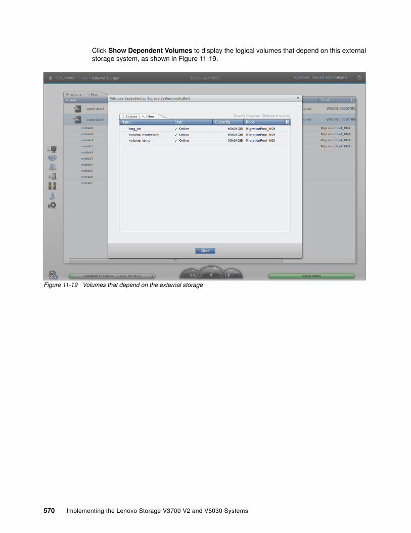
Click Show Dependent Volumes to display the logical volumes that depend on this external storage system, as shown in Figure 11-19.
Figure 11-19 Volumes that depend on the external storage
570 Implementing the Lenovo Storage V3700 V2 and V5030 Systems

From the Volumes Dependent on Storage System window, volume actions, such as Map to Host, Shrink, Expand, Migrate to Another Pool, and Add Volume Copy, are available, as shown in Figure 11-20.
Figure 11-20 Volume actions
In the Lenovo StorageV5030 virtualization environment, you can migrate your application data nondisruptively from one internal or external storage pool to another, simplifying storage management with less risk.
Volume copy is another key feature that you can benefit from by using Lenovo Storage V5030 virtualization. Two copies can be created to enhance availability for a critical application. A volume copy can be also used to generate test data or for data migration.
For more information about the volume actions of the Lenovo Storage V5030 storage system, see Chapter 8, “Advanced host and volume administration” on page 305.
Chapter 11. External storage virtualization 571

Returning to the External Storage window and the MDisks that are provided by this external storage system, you can highlight the name of an MDisk and right-click (or use the Actions drop-down menu) to see a menu of available options, as shown in Figure 11-21.
You can view the properties of an MDisk, its capacity, the storage pool, and the storage system that it belongs to. You can perform several actions on MDisks by using this menu, such as Assign, Import, Remove, Rename, and Dependent Volumes.
Figure 11-21 MDisk Actions menu in the External Storage window
572 Implementing the Lenovo Storage V3700 V2 and V5030 Systems

11.2.4 Removing external storage
If you want to remove the external storage systems from the Lenovo Storage V5030 virtualized environment, the following options are available:
� If you want to remove the external storage systems and discard the data on them, complete the following steps:
a. Stop any host I/O on the volumes.
b. Remove the volumes from the host file systems, logical volume, or volume group, and remove the volumes from the host device inventory.
c. Remove the host mapping of volumes and the volumes themselves on the Lenovo Storage V5030.
d. Remove the storage pools to which the external storage systems belong, or you can keep the storage pool and remove the MDisks of the external storage from the storage pools.
e. Unzone and disconnect the external storage systems from theLenovo Storage V5030.
f. Click Detect MDisks for the Lenovo Storage V5030 to discover the removal of the external storage systems.
� If you want to remove the external storage systems and keep the volumes and their data on the Lenovo Storage V5030, complete the following steps:
a. Migrate volumes and their data to other internal or external storage pools that are on the Lenovo StorageV5030.
b. Remove the storage pools to which the external storage systems belong, or you can keep the storage pools and remove the MDisks of the external storage from the storage pools.
c. Unzone and disconnect the external storage systems from the Lenovo Storage V5030.
d. Click Detect MDisks for theLenovo Storage V5030 to discover the removal of the external storage systems.
� If you want to remove the external storage systems from the Lenovo Storage V5030 control and keep the volumes and their data on other external storage systems, complete the following steps:
a. Migrate volumes and their data to other internal or external storage pools on the Lenovo Storage V5030, as described in Chapter 6, “Storage migration” on page 221.
b. Remove the storage pools to which the original external storage systems belong, or you can keep the storage pools and remove the MDisks of that external storage from the storage pools.
c. Export the volumes that were migrated in step a to image mode with the new MDisks on the target external storage systems. For more information about the restrictions and prerequisites for migration, see Chapter 6, “Storage migration” on page 221.
You must record pre-migration information, for example, the original Small Computer System Interface (SCSI) identifiers (IDs) that the volumes used when they were mapped to hosts. Certain operating systems do not support a change of the SCSI ID during migration. Unzone and disconnect the external storage systems from the Lenovo Storage V5030.
d. Click Detect MDisks for theLenovo Storage V5030 to discover the removal of the external storage systems.
Chapter 11. External storage virtualization 573

574 Implementing the Lenovo Storage V3700 V2 and V5030 Systems

Chapter 12. RAS, monitoring, and troubleshooting
This chapter describes the reliability, availability, and serviceability (RAS) features and ways to monitor and troubleshoot the Lenovo Storage V3700 V2, V3700 V2 XP, and V5030.
This chapter includes the following topics:
� 12.1, “Reliability, availability, and serviceability features” on page 576� 12.2, “System components” on page 577� 12.3, “Configuration backup” on page 594� 12.4, “System update” on page 597� 12.5, “Monitoring” on page 616� 12.6, “Audit log” on page 620� 12.7, “Event log” on page 622� 12.8, “Collecting support information” on page 630� 12.9, “Powering off the system and shutting down the infrastructure” on page 635
12
© Copyright Lenovo 2018. All rights reserved. 575

12.1 Reliability, availability, and serviceability features
This section describes the reliability, availability, and serviceability (RAS) features of the Lenovo Storage V3700 V2, V3700 V2 XP, and V5030, as well as monitoring and troubleshooting. RAS features are important concepts in the design of the Lenovo Storage V3700 V2, V3700 V2 XP, and V5030. Hardware and software features, design considerations, and operational guidelines all contribute to make the Lenovo Storage V3700 V2, V3700 V2 XP, and V5030 reliable.
Fault tolerance and a high level of availability are achieved with the following features:
� The RAID capabilities of the underlying disk subsystems� The software architecture that is used by the Lenovo Storage V3700 V2, V3700 V2 XP,
and V5030 nodes� Auto-restart of nodes that are stopped� Battery units to provide cache memory protection in a site power failure� Host system multipathing and failover support
High levels of serviceability are achieved with the following features:
� Cluster error logging
� Asynchronous error notification
� Dump capabilities to capture software-detected failures
� Concurrent diagnostic procedures
� Directed maintenance procedures
� Concurrent log analysis and memory dump data recovery tools
� Concurrent maintenance of all of the Lenovo Storage V3700 V2, V3700 V2 XP, and V5030components
� Concurrent upgrade of Lenovo Storage V3700 V2, V3700 V2 XP, and V5030 software and microcode
� Concurrent addition or deletion of a node canister in a cluster
� Software recovery through the Service Assistant Tool
� Automatic software version correction when a node is replaced
� Detailed status and error conditions that are displayed through the Service Assistant Tool
� Error and event notification through Simple Network Management Protocol (SNMP), syslog, and email
� Access to the Service Assistant Tool through the tech port for network connection problems
At the core of the Lenovo Storage V3700 V2, V3700 V2 XP, and V5030 are a redundant pair of node canisters. The two canisters share the load of transmitting and receiving data between the attached hosts and the disk arrays.
576 Implementing the Lenovo Storage V3700 V2 and V5030 Systems

12.2 System components
This section describes each of the components that make up the Leovo Storage V3700 V2, V3700 V2 XP, and V5030 systems. The components are described in terms of location, function, and serviceability.
12.2.1 Enclosure midplane
The enclosure midplane connects the node or expansion canisters to the power supply units and to the drives. The midplane is part of the enclosure midplane assembly, which consists of the midplane and the front section of the enclosure.
During the basic system configuration, vital product data (VPD) is written to the enclosure midplane. On a control enclosure midplane, the VPD contains information, such as worldwide node name (WWNN) 1, WWNN 2, machine type and model, machine part number, and serial number. On an expansion enclosure midplane, the VPD contains information, such as machine type and model, machine part number, and serial number.
The enclosure midplane is initially generic and it is configured as a control enclosure midplane or expansion enclosure midplane only when the VPD is written. After the VPD is written, a control enclosure midplane is no longer interchangeable with an expansion enclosure midplane and vice versa.
For information about the midplane replacement process, see the Leovo Storage V3700 V2, V3700 V2 XP, and V5030 Information Center at this website:
http://systemx.lenovofiles.com/help/topic/com.lenovo.storage.v3700.doc/v3700_rplc_enc_midplane_pwroff.html
At the website, browse to Lenovo Storage V3700 V2/V5030 Series → Troubleshooting → Replacing parts
12.2.2 Node canisters
Two node canister slots are on the top of the unit. The left slot is canister 1, and the right slot is canister 2.
Figure 12-1 shows the rear view of a fully equipped control enclosure.
Figure 12-1 Rear view of a control enclosure with two node canisters (the Lenovo Storage V3700 V2 XP)
Important: The enclosure midplane must be replaced only by a trained service support representative (SSR).
Chapter 12. RAS, monitoring, and troubleshooting 577

USB portsEach node canister has one USB port. The location of the port is the same on every model, and no indicators are associated with it.
Figure 12-2 shows the location of the USB port.
Figure 12-2 Node canister USB port (the Lenovo Storage V3700 V2 XP)
Ethernet portsThe Lenovo Storage V3700 V2 and Lenovo Storage V3700 V2 XP node canisters have two 10/100/1000 Mbps Ethernet ports. Both ports can be used for management, Internet Small Computer System Interface (iSCSI) traffic, and Internet Protocol (IP) replication. Additionally, port 2 can be used as a technician port (the white box with “T” in the center of the box) for system initialization and servicing.
Figure 12-3 shows the Ethernet ports on the Lenovo Storage V3700 V2.
Figure 12-3 Lenovo Storage V3700 V2 Ethernet ports
Figure 12-4 shows the Ethernet ports on the Lenovo Storage V3700 V2 XP.
Figure 12-4 Lenovo Storage V3700 V2 XP Ethernet ports
578 Implementing the Lenovo Storage V3700 V2 and V5030 Systems

Each Lenovo Storage V5030 node canister has two 1/10 Gbps Ethernet ports and one Ethernet technician port. Port 1 and 2 can be used for management, iSCSI traffic, and IP replication. Port T can be used as a technician port for system initialization and service only.
Figure 12-5 shows the Ethernet ports on the Lenovo Storage V5030.
Figure 12-5 Lenovo Storage V5030 Ethernet ports
Each port has two LEDs that display the status of its activity. Their meanings are shown in Table 12-1.
Table 12-1 Ethernet port status LEDs
Serial-attached SCSI portsEach Lenovo Storage V3700 V2 node canister uses one 12 Gbps serial-attached SCSI (SAS) port to connect optional expansion enclosures. This port does not support host attachment.
Figure 12-6 shows the SAS ports on the Lenovo Storage V3700 V2.
Figure 12-6 Lenovo Storage V3700 V2 SAS ports
Name and position
Color State Meaning
Activity (left)
Green Flashing The link is active.
Off The link is inactive.
Link speed(right)
Green Solid A connection exists to a remote device at 1 Gbps or more.
Off No connection exists to a remote device, or the link is connected at less than 1 Gbps.
Chapter 12. RAS, monitoring, and troubleshooting 579

Each Lenovo Storage V3700 V2 XP node canister has three 12 Gbps SAS ports. Port 1 can be used to connect optional expansion enclosures, and ports 2 and 3 can be used for host attachment.
Figure 12-7 shows the SAS ports on the Lenovo Storage V3700 V2 XP.
Figure 12-7 Lenovo Storage V3700 V2 XP SAS ports
Each Lenovo Storage V5030 node canister has two 12 Gbps SAS ports to connect optional expansion enclosures. This port does not support host attachment.
Figure 12-8 shows the SAS ports on the Lenovo Storage V5030.
Figure 12-8 LenovoS torage V5030 SAS ports
Each port has two LEDs that display the status of its activity. Their meanings are shown in Table 12-2.
Table 12-2 SAS port status LEDs
Name and position
Color State Meaning
Fault (left)
Amber Solid One of the following errors exists:� Only 1, 2, or 3 lanes (phys) have a connection.� Not all of the lanes (phys) that have a
connection are running at the same speed.� Not all of the lanes (phys) that have a
connection are attached to the same address.� An unsupported device is connected to the port.
Off No fault exists. All four lanes (phys) have a connection.
Link (right)
Green Solid A connection exists on at least one lane (phy).
Off No connection exists on any lane (phy).
580 Implementing the Lenovo Storage V3700 V2 and V5030 Systems

Battery statusEach node canister houses a battery, the status of which is displayed by two LEDs on the back of the unit, as shown in Figure 12-9.
Figure 12-9 Battery status LEDs (the Lenovo Storage V3700 V2 XP)
The meaning of each LED is described in Table 12-3.
Table 12-3 Battery status LEDs
Canister statusThe status of each canister is displayed by three LEDs on the back of the unit, as shown in Figure 12-10.
Figure 12-10 Node canister status LEDs (the Lenovo Storage V3700 V2 XP)
Name and position
Color State Meaning
Battery status (left)
Green Solid The battery is fully charged and has sufficient charge to complete two “fire hose” dumps.
Blinking The battery has sufficient charge to complete a single fire hose dump only.
Fast blinking The battery is charging and has insufficient charge to complete a single fire hose dump.
Off The battery is not available for use.
Fault (right) Amber Solid A battery fault might compromise normal operations.
Slow blinking A non-critical battery fault exists.
Off No known conditions prevent normal operation, except conditions that might be reported by the status LED.
Chapter 12. RAS, monitoring, and troubleshooting 581

The meaning of each LED is described in Table 12-4.
Table 12-4 Canister status LEDs
Name and position
Color State Meaning
Power (left) Green Solid The canister is powered on and the Lenovo Storage V3700 V2, V3700 V2 XP, and V5030 codes are running.
Blinking fast Power is available, and the canister is running a self-test.
Blinking slowly
Power is available and the canister is in standby mode, which means that the Lenovo Storage V3700 V2, V3700 V2 XP, and V5030 codes are not running.
Off No power is available, or the power is coming from the battery.
Status (middle)
Green Solid The canister is part of a cluster.
Blinking fast The canister is carrying out a fire hose dump.
Blinking The canister is in candidate or service state, which means that it cannot perform I/O. It is safe to remove the canister.
Off No power exists to the canister. The canister is in standby mode. The canister is running a self-test. Or, the operating system is loading.
Fault (right) Amber Solid The canister is in the service state, or an error is stopping the software from starting.
Blinking The canister is being identified. A fault might or might not exist.
Off The canister is in the candidate or active state. A hardware error might exist. Any error that was detected is not severe enough to stop the node from participating in a cluster. The canister might not have power.
582 Implementing the Lenovo Storage V3700 V2 and V5030 Systems

Replaceable componentsThe Leovo Storage V3700 V2, V3700 V2 XP, and V5030 node canisters contain the following field-replaceable (client-replaceable) components:
� Host Interface Card� Memory� Battery
Figure 12-11 shows the location of these parts within the node canister.
Figure 12-11 Node canister client-replaceable components
Host Interface Card replacement procedureFor information about the Host Interface Card (HIC) replacement process, see the Leovo Storage V3700 V2, V3700 V2 XP, and V5030 Information Center at this website:
http://systemx.lenovofiles.com/help/index.jsp?topic=%2Fcom.lenovo.storage.common.nav.doc%2Foverview_storage_solutions.html
Note: Because these components are inside the node canister, their replacement leads to a redundancy loss until the replacement is complete.
Chapter 12. RAS, monitoring, and troubleshooting 583

At the website, browse to Lenovo Storage V3700 V2/V5030 Series → Troubleshooting → Replacing parts → Replacing a host interface adapter. Figure 12-12 shows a HIC replacement.
Figure 12-12 HIC replacement
Memory replacement procedureFor information about the memory replacement process, see the Leovo Storage V3700 V2, V3700 V2 XP, and V5030 Information Center at this website:
http://systemx.lenovofiles.com/help/topic/com.lenovo.storage.v5030.7.8.1.doc/v3700_rplc_nodecan_dimm.html
At the website, browse to Lenovo Storage V3700 V2/V5030 Series →Troubleshooting → Replacing parts → Replacing a node canister memory module.
Figure 12-13 on page 585 shows a memory replacement.
Note: The memory modules do not stand up. They lie in a cascading fashion.
584 Implementing the Lenovo Storage V3700 V2 and V5030 Systems

Figure 12-13 Memory replacement
Battery Backup Unit replacement procedure
Because the Battery Backup Unit (BBU) replacement leads to a redundancy loss until the replacement is complete, we advise that you replace the BBU only when you are instructed to replace it. We advise you to follow the Directed Maintenance Procedure (DMP).
During the procedure, while you lift and lower the battery, grasp the blue handle on each end of the battery and keep the battery parallel to the canister system board, as shown in Figure 12-14.
Figure 12-14 BBU replacement
Attention: The battery is a lithium ion battery. To avoid a possible explosion, do not incinerate the battery. Exchange the battery only with the part that is approved by IBM.
Chapter 12. RAS, monitoring, and troubleshooting 585

For more information about the BBU replacement process, see the Lenovo Information Center at this website:
http://systemx.lenovofiles.com/help/topic/com.lenovo.storage.v5030.7.8.1.doc/tbrd_rmvrplparts_1955wm.html
At the website, browse to Lenovo Storage V3700 V2/V5030 Series → Troubleshooting →Replacing parts → Replacing
12.2.3 Expansion canisters
Two expansion canister slots are on the top of the unit. As with the control enclosure, the left slot is canister 1 and the right slot is canister 2.
Figure 12-15 shows the rear view of a fully equipped expansion enclosure.
Figure 12-15 Rear view of an expansion enclosure with two expansion canisters
SAS portsSAS ports are used to connect the expansion canister to the node canister or to an extra expansion canister in the chain. Figure 12-16 shows the SAS ports that are on the expansion canister.
Figure 12-16 Expansion canister SAS ports
Each port has two LEDs that display the status of its activity. Their meanings are shown in Table 12-5 on page 587.
Important: During the replacement, the battery must be kept parallel to the canister system board while the battery is removed or replaced. Keep equal force, or pressure, on each end.
586 Implementing the Lenovo Storage V3700 V2 and V5030 Systems

Table 12-5 SAS port status LEDs
Canister statusThe status of each expansion canister is displayed by three LEDs on the back of the unit, as shown in Figure 12-17.
Figure 12-17 Enclosure canister status LEDs
The meaning of each LED is described in Table 12-6.
Table 12-6 Expansion canister status LEDs
Name and position
Color State Meaning
Fault (left) Amber Solid One of the following errors exists:� Only 1, 2, or 3 lanes (phys) have a connection.� Not all of the lanes (phys) that have a
connection are running at the same speed.� Not all of the lanes (phys) that have a
connection are attached to the same address.� An unsupported device is connected to the port.
Off No fault exists. All four lanes (phys) have a connection.
Link (right) Green Solid A connection exists on at least one lane (phy).
Off No connection exists on any lane (phy).
Name and position
Color State Meaning
Power (left) Green Solid The canister is receiving power.
Off No power is available, or the power is coming from the battery.
Status (middle)
Green Solid The canister is running normally.
Blinking The canister is unable to read data from the midplane.
Off The system is off, in standby, or running a self-test, or the operating system is loading.
Chapter 12. RAS, monitoring, and troubleshooting 587

12.2.4 Disk subsystem
This section describes the parts of the Leovo Storage V3700 V2, V3700 V2 XP, and V5030 disk subsystem, which is made up of control and expansion enclosures.
The Lenovo Storage V3700 V2 and Lenovo Storage V3700 V2 XP can have one control enclosure. The Lenovo Storage V5030 can have 1 or 2 control enclosures.
Each Lenovo Storage V3700 V2 and Lenovo Storage V3700 V2 XP control enclosure can attach up to 10 expansion enclosures (with firmware v7.8.1.3 or above). Each Lenovo Storage V5030 control enclosure can attach up to 20 expansion enclosures.
SAS cablingExpansion enclosures are attached to control enclosures and between each other by using SAS cables.
A set of correctly interconnected enclosures is called a chain. Each chain is made up of two strands. A strand runs through the canisters that are in the same position in each enclosure in the chain. Canister 1 of an enclosure is cabled to canister 1 of the downstream enclosure. Canister 2 of an enclosure is cabled to canister 2 of the downstream enclosure.
A strand starts with a SAS initiator chip inside an Leovo Storage V3700 V2, V3700 V2 XP, and V5030 node canister and progresses through SAS expanders, which connect to the disk drives. Each canister contains an expander. Each drive has two ports, each of which is connected to a different expander and strand. This configuration means that both nodes directly access each drive, and no single point of failure exists.
At system initialization, when devices are added to or removed from strands (and at other times), the Leovo Storage V3700 V2, V3700 V2 XP, and V5030 software perform a discovery process to update the state of the drive and enclosure objects.
The Lenovo Storage V3700 V2 supports one SAS chain for each control enclosure, and up to 10 expansion enclosures (with firmware v7.8.1.3 or above) can be attached to this chain. The node canister uses SAS port 1 for expansion enclosures.
Figure 12-18 on page 589 shows the SAS cabling on a Lenovo Storage V3700 V2 with three attached expansion enclosures.
Fault (right) Amber Solid A fault requires part replacement, or the canister is still starting.
Blinking The canister is being identified. A fault might or might not exist.
Off The canister has no faults that require part replacement.
Name and position
Color State Meaning
588 Implementing the Lenovo Storage V3700 V2 and V5030 Systems

Figure 12-18 SAS expansion cabling on the Lenovo Storage V3700 V2
The Lenovo Storage V3700 V2 XP supports one SAS chain for each control enclosure, and up to 10 expansion enclosures ((with firmware v7.8.1.3 or above) can be attached to this chain. The node canister uses SAS port 1 for expansion enclosures.
Figure 12-19 shows the SAS cabling on a Lenovo Storage V3700 V2 XP with three attached expansion enclosures.
Figure 12-19 SAS expansion cabling on the Lenovo Storage V3700 V2 XP
Chapter 12. RAS, monitoring, and troubleshooting 589
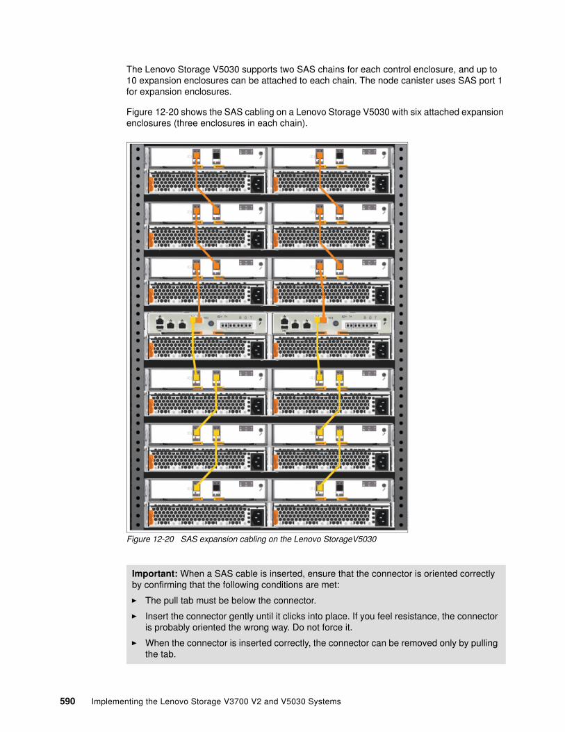
The Lenovo Storage V5030 supports two SAS chains for each control enclosure, and up to 10 expansion enclosures can be attached to each chain. The node canister uses SAS port 1 for expansion enclosures.
Figure 12-20 shows the SAS cabling on a Lenovo Storage V5030 with six attached expansion enclosures (three enclosures in each chain).
Figure 12-20 SAS expansion cabling on the Lenovo StorageV5030
Important: When a SAS cable is inserted, ensure that the connector is oriented correctly by confirming that the following conditions are met:
� The pull tab must be below the connector.
� Insert the connector gently until it clicks into place. If you feel resistance, the connector is probably oriented the wrong way. Do not force it.
� When the connector is inserted correctly, the connector can be removed only by pulling the tab.
590 Implementing the Lenovo Storage V3700 V2 and V5030 Systems

Drive slotsThe Leovo Storage V3700 V2, V3700 V2 XP, and V5030 have different types of enclosures, depending on the model, warranty, and number of drive slots.
Table 12-7 shows the drive slots on each enclosure type.
Table 12-7 Drive slots for each enclosure type
Drive replacement procedureYou can reseat or replace a failed drive in a Leovo Storage V3700 V2, V3700 V2 XP, and V5030 by removing it from its enclosure and replacing it with the correct new drive without requiring the Directed Maintenance Procedure to supervise the service action.
The system can automatically perform the drive hardware validation tests and can promote the drive into the configuration if these tests pass, automatically configuring the inserted drive as a spare. The status of the drive after the promotion can be recorded in the event log either as an informational message or an error if a hardware failure occurs during the system action.
For more information about the drive replacement process, see the Leovo Storage V3700 V2, V3700 V2 XP, and V5030 Information Center at this website:
http://systemx.lenovofiles.com/help/index.jsp?topic=%2Fcom.lenovo.storage.common.nav.doc%2Foverview_storage_solutions.html
At the website, browse to Lenovo Storage V3700 V2/V5030 Series → Troubleshooting → Replacing parts → Replacing a 3.5 inch drive assembly or Replacing a 2.5 inch drive assembly.
Enclosure type Drive slots
� Control enclosure 6535-HC1 � Control enclosure 6535-HC2� Expansion enclosure 6535-HC7
12 x 3.5-inch slots
� Control enclosure 6535-HC4� Control enclosure 6535-HC5� Expansion enclosure 6535-HC8
24 x 2.5-inch slots
Chapter 12. RAS, monitoring, and troubleshooting 591

12.2.5 Power supply units
All enclosures require two power supply units (PSUs) for normal operation. A single PSU can power the entire enclosure for redundancy. We advise that you supply AC power to each PSU from different power distribution units (PDUs).
Figure 12-21 shows a fully equipped control enclosure with two supply units. The PSUs are identical between the control and expansion enclosures.
Figure 12-21 Power supply units
The left PSU is numbered 1, and the right PSU is numbered 2.
Power supplies in both control and expansion enclosures are hot-swappable and replaceable without a need to shut down a node or cluster. If the power is interrupted in one node canister for less than 2.5 seconds, the canister cannot perform a fire hose dump and continues operation from battery.
592 Implementing the Lenovo Storage V3700 V2 and V5030 Systems
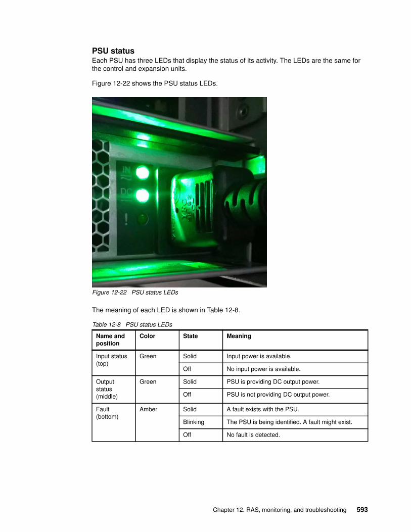
PSU statusEach PSU has three LEDs that display the status of its activity. The LEDs are the same for the control and expansion units.
Figure 12-22 shows the PSU status LEDs.
Figure 12-22 PSU status LEDs
The meaning of each LED is shown in Table 12-8.
Table 12-8 PSU status LEDs
Name and position
Color State Meaning
Input status (top)
Green Solid Input power is available.
Off No input power is available.
Output status (middle)
Green Solid PSU is providing DC output power.
Off PSU is not providing DC output power.
Fault (bottom)
Amber Solid A fault exists with the PSU.
Blinking The PSU is being identified. A fault might exist.
Off No fault is detected.
Chapter 12. RAS, monitoring, and troubleshooting 593

PSU replacement procedureFor information about the PSU replacement process, see the Leovo Storage V3700 V2, V3700 V2 XP, and V5030 Information Center at this website:
http://systemx.lenovofiles.com/help/index.jsp?topic=%2Fcom.lenovo.storage.common.nav.doc%2Foverview_storage_solutions.html
At the website, browse to Lenovo Storage V3700 V2/V5030 Series →Troubleshooting → Replacing parts → Replacing
12.3 Configuration backup
The configuration backup file must be used if a serious failure occurs that requires the system configuration to be restored. The file contains configuration data of arrays, pools, volumes, and so on (but no client data).
The configuration backup file can be downloaded and saved by using the graphical user interface (GUI) or the command-line interface (CLI). The CLI option requires you to log in to the system and download the file by using Secure Copy Protocol (SCP). It is a preferred practice for an automated backup of the configuration.
The backup file is updated by the cluster every day and stored in the /dumps directory. Even so, it is important to start a manual backup after you change your system configuration.
To successfully perform the configuration backup, follow the prerequisites and requirements:
� All nodes must be online.� No independent operations that change the configuration can be running in parallel.� No object name can begin with an underscore.
12.3.1 Generating a manual configuration backup by using the CLI
You can use the CLI to trigger a configuration backup either manually on an ad hoc basis or by an automatic process regularly. The svcconfig backup command generates a new backup file. Triggering a backup by using the GUI is not possible, but you can save the output from the GUI.
Example 12-1 shows the output of the svcconfig backup command.
Example 12-1 Triggering a backup by using the CLI
>svcconfig backup
Important: Save the configuration files of the Leovo Storage V3700 V2, V3700 V2 XP, and V5030 regularly. The best approach is to save daily and automate this task. Always perform the additional manual backup before you perform any critical maintenance task, such as an update of the microcode or software version.
Important: You can perform an ad hoc backup of the configuration only from the CLI. However, the output of the command can be downloaded from both the CLI and the GUI.
594 Implementing the Lenovo Storage V3700 V2 and V5030 Systems

..................................................................................
..................................................................................
....................CMMVC6155I SVCCONFIG processing completed successfully
The svcconfig backup command creates three files that provide information about the backup process and cluster configuration. These files are created in the /dumps directory on the configuration node and can be retrieved by using SCP. Use the lsdumps command to list them, as shown in Example 12-2.
Example 12-2 Listing the backup files by using the CLI
>lsdumpsid filename ...48 svc.config.backup.xml_7810001-1 49 svc.config.backup.sh_7810001-1 50 svc.config.backup.log_7810001-1 ...
The three files that are created by the backup process are described in Table 12-9.
Table 12-9 Files that are created by the backup process
12.3.2 Downloading a configuration backup by using the GUI
The Leovo Storage V3700 V2, V3700 V2 XP, and V5030 do not offer an option to initiate a backup from the GUI. However, you can download existing daily backups or manual backups that were triggered from the CLI.
To download a configuration backup file by using the GUI, complete the following steps:
1. Browse to Settings → Support and select Show full log listing to list all of the available log files that are stored on the configuration node, as shown in Figure 12-23 on page 596.
File name Description
svc.config.backup.xml_<serial> This file contains the cluster configuration data.
svc.config.backup.sh_<serial> This file contains the names of the commands that were issued to create the backup of the cluster.
svc.config.backup.log_<serial> This file contains details about the backup, including any error information that might be reported.
Chapter 12. RAS, monitoring, and troubleshooting 595

Figure 12-23 Full log listing option
2. Search for the files that are named svc.config.backup.xml_*, svc.config.backup.sh_*, and svc.config.backup.log_*. Select the files, right-click, and select Download, as shown in Figure 12-24.
Figure 12-24 Backup files download
596 Implementing the Lenovo Storage V3700 V2 and V5030 Systems

Even though the configuration backup files are updated automatically daily, it might be useful to verify the time stamp of the actual file. Open the svc.config.backup.xml_xx file with a text editor and search for the string timestamp=, which is near the top of the file. Figure 12-25 shows the file and the timestamp information.
Figure 12-25 Timestamp in the backup xml file
12.4 System update
The system update process involves updating the entire Lenovo Storage V3700 V2, V3700 V2 XP, and V5030 environment.
The node canister software and the drive firmware are updated separately so these tasks are described in different topics.
12.4.1 Updating node canister software
For information about the latest software and to download the software package, go to the following Lenovo Support website:
http://systemx.lenovofiles.com/help/topic/com.lenovo.storage.v3700.doc/svc_updatetestutility.html
The GUI also shows whether a software update is available and the latest software level when you navigate to Settings → System → Update System, as shown in Figure 12-26 on page 598.
Chapter 12. RAS, monitoring, and troubleshooting 597

Figure 12-26 Latest software level available
Important: Certain levels of code support updates only from specific previous levels. If you update to more than one level above your current level, you might be required to install an intermediate level. For information about on update compatibility, see this website:
http://systemx.lenovofiles.com/help/topic/com.lenovo.storage.v3700.doc/svc_updatetestutility.html
598 Implementing the Lenovo Storage V3700 V2 and V5030 Systems

Preparing for the updateAllow sufficient time to plan your tasks, review your preparatory update tasks, and complete the update of the Lenovo Storage V3700 V2, V3700 V2 XP, and V5030 environment. The update procedures can be divided into the following general update tasks, as shown in Table 12-10.
Table 12-10 Software update tasks
The amount of time that it takes to perform a node canister update can vary depending on the amount of preparation work that is required and the size of the environment. Generally, to update the node software, allow 20 - 40 minutes for each node canister and a single 30-minute wait when the update is halfway complete. One node in each I/O group can be upgraded to start, then the system can wait 30 minutes before it upgrades the second node in each I/O group. The 30-minute wait allows the recently updated node canister to come online and be confirmed as operational, and it allows time for the host multipath to recover.
The software update can be performed concurrently with normal user I/O operations. After the updating node is unavailable, all I/O operations fail to that node and the failed I/O operations are directed to the partner node of the working pair. Applications do not see any I/O failures.
The maximum I/O rate that can be sustained by the system might degrade while the code is uploaded to a node, the update is in progress, the node is rebooted, and the new code is committed because write caching is disabled during the node canister update process.
Sequence Upgrade tasks
1 Decide whether you want to update automatically or manually. During an automatic update procedure, the clustered system updates each of the nodes systematically. The automatic method is the preferred procedure for updating software on nodes. However, you can update each node manually.
2 Ensure that Common Information Model (CIM) object manager (CIMOM) clients are working correctly. When necessary, update these clients so that they can support the new version of the Lenovo Storage V3700 V2, V3700 V2 XP, and V5030 code. Examples can be operating system (OS) versions and options, such as FlashCopy Manager or VMware plug-ins.
3 Ensure that multipathing drivers in the environment are fully redundant. If you experience failover issues with multipathing driver support, resolve these issues before you start normal operations.
4 Update other devices in the Lenovo Storage V3700 V2, V3700 V2 XP, and V5030 environment. Examples might include updating the hosts and switches to the correct levels.
5 Update your Lenovo Storage V3700 V2, V3700 V2 XP, and V5030.
Important: Ensure that no unfixed errors are in the log and that the system date and time are correctly set before you start the update.
Important: Ensure that the multipathing drivers are fully redundant with every available path and online. You might see errors that are related to the paths, which can go away (failover) and the error count can increase during the update. When the paths to the nodes return, the nodes fall back to become a fully redundant system.
Chapter 12. RAS, monitoring, and troubleshooting 599

When new nodes are added to the system, the upgrade package is automatically downloaded to the new nodes from the Lenovo Storage V3700 V2, V3700 V2 XP, and V5030 system.
Update test utilityThe Lenovo Storage V3700 V2, V3700 V2 XP, and V5030 update test utility checks for known issues that can cause problems during a software update. You can download the utility and read more about it atLenovo Information Center websites:
https://datacentersupport.lenovo.com/tw/en/products/storage/lenovo-storage/v3700v2/6535/downloads
https://datacentersupport.lenovo.com/tw/en/products/storage/lenovo-storage/v5030/6536/downloads
The software update test utility can be downloaded in advance of the update process, or it can be downloaded and run directly during the software update, as guided by the update wizard. You can run the utility multiple times on the same system to perform a readiness check-in preparation for a software update.
The installation and use of this utility is nondisruptive, and it does not require a restart of any node. Therefore, host I/O is not interrupted. The utility is only installed on the current configuration node.
System administrators must continue to check whether the version of code that they plan to install is the latest version.
Updating the software automatically by using the GUIComplete the following steps to automatically update the node canister software by using the GUI:
1. Browse to Settings → System → Update System and select Update and Test, as shown in Figure 12-27.
Figure 12-27 Update system panel
Alternatively, you can run only the test utility by selecting Test Only.
600 Implementing the Lenovo Storage V3700 V2 and V5030 Systems

2. Select the test utility and update package files by clicking the folder icons, as shown in Figure 12-28. The code levels are entered automatically.
Figure 12-28 File selection
Alternatively, for the Test Only option, upload only the test utility and enter the code level manually.
3. Select Automatic update and click Finish to start the update process, as shown in Figure 12-29. The Automatic update option is the default and advised choice.
Figure 12-29 Automatic update selection
4. Wait for the test utility and update package to upload to the system, as shown in Figure 12-30.
Figure 12-30 File upload
Chapter 12. RAS, monitoring, and troubleshooting 601

5. After the files upload, the test utility is automatically run, as shown in Figure 12-31. The test utility verifies that no issues exist with the current system environment, such as failed components and drive firmware that is not at the latest level.
Figure 12-31 State while the test utility runs
If the test utility discovers any warnings or errors, a window opens to inform the user, as shown in Figure 12-32. Close the window and then click Read more to get more information.
Figure 12-32 Warning about the issues that were detected
602 Implementing the Lenovo Storage V3700 V2 and V5030 Systems
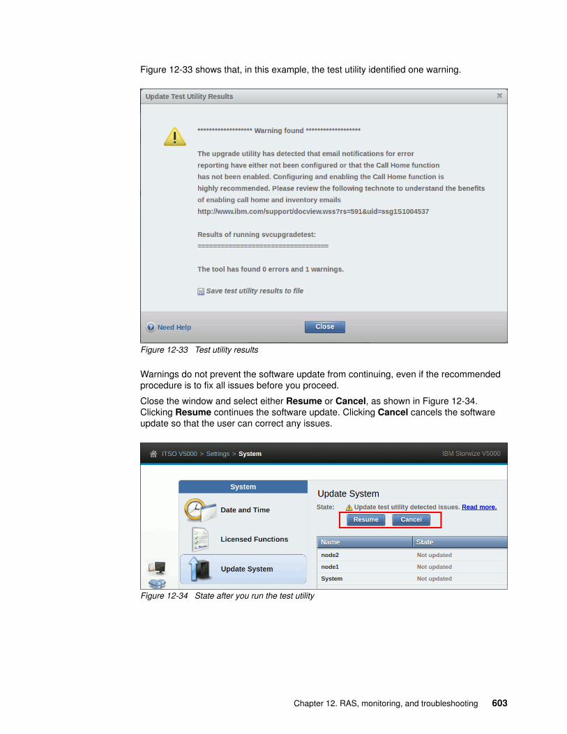
Figure 12-33 shows that, in this example, the test utility identified one warning.
Figure 12-33 Test utility results
Warnings do not prevent the software update from continuing, even if the recommended procedure is to fix all issues before you proceed.
Close the window and select either Resume or Cancel, as shown in Figure 12-34. Clicking Resume continues the software update. Clicking Cancel cancels the software update so that the user can correct any issues.
Figure 12-34 State after you run the test utility
Chapter 12. RAS, monitoring, and troubleshooting 603

Selecting Resume prompts the user to confirm the action, as shown in Figure 12-35.
Figure 12-35 Resume confirmation window
6. Wait for each node to be updated and rebooted, one at a time until the update process is complete. The GUI displays the overall progress of the update and the current state of each node, as shown in Figure 12-36.
Figure 12-36 Automatic update progress
During the update process, a node fails over and you can temporarily lose connection to the GUI. After this situation happens, a warning is displayed, as shown in Figure 12-37. Select Yes.
Figure 12-37 Configuration node failover warning
604 Implementing the Lenovo Storage V3700 V2 and V5030 Systems

Updating the software manually by using the GUI and SAT
Complete the following steps to manually update the software by using the GUI and Service Assistant Tool (SAT):
1. Browse to Settings → System → Update System and select Update and Test, as shown in Figure 12-38.
Figure 12-38 Update system panel
Alternatively, you can run the test utility by selecting Test Only.
2. Select the test utility and update package files by clicking the folder icons, as shown in Figure 12-39. The code levels are entered automatically.
Figure 12-39 File selection
Alternatively, for the Test Only option, upload only the test utility and enter the code level manually.
Important: We advise that you update the Lenovo Storage V3700 V2, V3700 V2 XP, and V5030 automatically by following the update wizard. If a manual update is used, ensure that you do not skip any steps.
Chapter 12. RAS, monitoring, and troubleshooting 605

3. Select Service Assistant Manual update and click Finish, as shown in Figure 12-40.
Figure 12-40 Manual update selection
4. Wait for the test utility and update package to upload to the system, as shown in Figure 12-41.
Figure 12-41 File upload
606 Implementing the Lenovo Storage V3700 V2 and V5030 Systems

5. After the files upload, the test utility is automatically run, as shown in Figure 12-42. The test utility verifies that no issues exist with the current system environment, such as failed components and drive firmware that is not at the latest level.
Figure 12-42 State while the test utility runs
If the utility identifies no issues, the system is ready for the user to initiate the manual upgrade, as shown in Figure 12-43.
Figure 12-43 State while you wait for the manual upgrade to start
Chapter 12. RAS, monitoring, and troubleshooting 607

6. Choose a node to update. Non-configuration nodes must be updated first. Update the configuration node last. Browse to Monitoring → System and hover over the canisters to confirm the nodes that are the non-configuration nodes, as shown in Figure 12-44.
Figure 12-44 Checking the configuration node status
7. Right-click the canister that contains the node that you want to update and select Remove, as shown in Figure 12-45.
Figure 12-45 Removing a node canister
Important: Ensure that you select the non-configuration nodes first.
608 Implementing the Lenovo Storage V3700 V2 and V5030 Systems

A warning message appears to ask whether you want to remove the node, as shown in Figure 12-46. Click Yes.
Figure 12-46 Node removal confirmation window
The non-configuration node is removed from the management GUI Update System panel and is shown as Unconfigured when you hover over the node after you select Monitoring → System.
8. Open the Service Assistant Tool for the node that you removed.
9. In the Service Assistant Tool, ensure that the node that is ready for update is selected. The node can be in the Service status, display a 690 error, and show no available cluster information, as shown in Figure 12-47.
Figure 12-47 Node to update in the Service Assistant Tool
Chapter 12. RAS, monitoring, and troubleshooting 609

10.In the Service Assistant Tool, select Update Manually, and choose the required node canister software upgrade file, as shown in Figure 12-48.
Figure 12-48 Starting the update in the Service Assistant Tool
11.Click Update to start the update process on the first node and wait for the node to finish updating.
Non-configuration nodes can be reintroduced automatically into the system after the update finishes. Updating and adding the node again can last 20 - 40 minutes.
The management GUI shows the progress of the update, as shown in Figure 12-49.
Figure 12-49 Manual update progress
12.Repeat steps 7 - 12 for the remaining nodes, leaving the configuration node until last.
610 Implementing the Lenovo Storage V3700 V2 and V5030 Systems

13.After you remove the configuration node from the cluster, you are asked whether you want to refresh the panel, as shown in Figure 12-50. Select Yes.
Figure 12-50 Configuration node failover warning
14.To exit the Service state, browse to the Home panel of the Service Assistant Tool and open the Actions menu. Select Exit Service State and click GO, as shown in Figure 12-51.
Figure 12-51 Exiting the Service state in the Service Assistant Tool
12.4.2 Updating the drive firmware
Drive firmware can be updated for all drives at the same time or individually.
To get the latest drive update package, go to the Drivers& Software Lenovo Storage V3700 V2, V3700 V2 XP, and V5030 support websites:
https://datacentersupport.lenovo.com/tw/en/products/storage/lenovo-storage/v3700v2/6535/downloads
https://datacentersupport.lenovo.com/tw/en/products/storage/lenovo-storage/v5030/6536/downloads
Important: The configuration node remains in the Service state when it is added to the cluster again. Therefore, you need to exit the Service state manually.
Chapter 12. RAS, monitoring, and troubleshooting 611

Updating the firmware on individual drivesTo update an individual drive, navigate to Pools → Internal Storage, right-click the drive to update, and select Upgrade from the Actions menu, as shown in Figure .
Individual drive updateSelect the upgrade package, which was downloaded from the Lenovo Support site, by clicking the folder icon, and click Upgrade, as shown in Figure on page 613.
612 Implementing the Lenovo Storage V3700 V2 and V5030 Systems

Individual drive update file selectionThe drive firmware update takes about 2 - 3 minutes for each drive.
To verify the new firmware level, right-click the drive and select Properties, as shown in Figure 12-52.
Figure 12-52 Individual drive update result
Updating the firmware on all drivesTwo methods are available in the management GUI to update all of the drives in an Lenovo Storage V3700 V2, V3700 V2 XP, and V5030:
� Through the Monitoring → System panel� Through the Pools → Internal Storage panel
Chapter 12. RAS, monitoring, and troubleshooting 613

Figure 12-53 shows how to update all of the drives through the Actions menu in the System panel by clicking Update → Drives.
Figure 12-53 Update of multiple drives in the System panel
614 Implementing the Lenovo Storage V3700 V2 and V5030 Systems

Figure 12-54 shows how to update all drives through the Actions menu in the Internal Storage panel. Under Drive Class Filter, click All Internal. In the Actions menu, click Upgrade All.
Figure 12-54 Update of multiple drives in the Internal Storage panel
After you initiate the drive upgrade process by either of the previous two options, the panel in Figure 12-55 is displayed. Select the drive upgrade package, which was downloaded from the Lenovo Support site, by clicking the folder icon, and click Upgrade.
Figure 12-55 Upload the software upgrade package for multiple drives
Note: If any drives are selected, the Actions menu displays actions for the selected drives and the Upgrade All option does not appear. If a drive is selected, deselect it by holding down the Ctrl key and clicking the drive.
Chapter 12. RAS, monitoring, and troubleshooting 615

All drives that require an update can now be updated.
12.5 Monitoring
Any issue that is reported by your Lenovo Storage V3700 V2, V3700 V2 XP, and V5030 systems must be fixed as soon as possible. Therefore, it is important to configure the system to send automatic notifications when a new event is reported. You can select the type of event for which you want to be notified. For example, you can restrict notifications to only events that require immediate action.
Several event notification mechanisms are available:
Email Email notifications can be configured to send emails to one or more email addresses. With this mechanism, individuals can receive notifications wherever they have email access, including mobile devices.
SNMP SNMP notifications can be configured to send a Simple Network Management Protocol (SNMP) traps report to a data center management system that consolidates SNMP reports from multiple systems. With this mechanism, you can monitor your data center from a single workstation.
Syslog Syslog notifications can be configured to send a syslog report to a data center management system that consolidates syslog reports from multiple systems. With this mechanism, you can monitor your data center from a single location.
If your system is within warranty, or you have a hardware maintenance agreement, configure your Lenovo Storage V3700 V2, V3700 V2 XP, and V5030 systems to send email events directly to IBM if an issue that requires hardware replacement is detected. This mechanism is known as Call Home. When an event is received, IBM automatically opens a problem report and, if appropriate, contacts you to verify whether replacement parts are required.
12.5.1 Email notifications and Call Home
The Call Home function of the Lenovo Storage V3700 V2, V3700 V2 XP, and V5030 use the email notification mechanism to send emails to the specific Lenovo Support Center. You enable Call Home by configuring email notifications. Then, you can optionally add other email addresses to notify.
Important: If you set up Call Home to the IBM Support Center, ensure that the contact details that you configured are correct and kept up-to-date when personnel changes.
616 Implementing the Lenovo Storage V3700 V2 and V5030 Systems

To configure Call Home and other optional email addresses, complete the following steps:
1. Browse to Settings → Notifications → Email and select Enable Notifications, as shown in Figure 12-56.
Figure 12-56 Enabling email notifications
For the correct functionality of email notifications, ensure that Simple Mail Transfer Protocol (SMTP) is enabled on the management network and not, for example, blocked by firewalls.
2. Provide the information about the location of the system, as shown in Figure 12-57, and click Next. Ensure that you always keep this information up-to-date.
Figure 12-57 System location
Chapter 12. RAS, monitoring, and troubleshooting 617

3. Provide the contact information of the system owner, who can be contacted by the IBM Support Center when necessary, as shown in Figure 12-58. Click Apply and Next. Ensure that you always keep this information up-to-date.
Figure 12-58 Contact information
4. Configure the SMTP servers. You can add several servers by clicking the plus (+) sign, as shown in Figure 12-59. When the correct SMTP server is provided, you can test the connectivity by using Ping.
Figure 12-59 Email servers
5. Click Apply and Next. After you exit the wizard, the support email address can be configured. This email is predefined by the system during this initial configuration and cannot be altered. The type of emails that are sent to the IBM Support Center cannot be altered either.
The emails include an inventory report that describes the system hardware and critical configuration information. Object names and other information, such as IP addresses, are not sent. Based on the information that is received, IBM can inform you whether the hardware or software that you are using requires an upgrade because of a known issue.
618 Implementing the Lenovo Storage V3700 V2 and V5030 Systems

6. Select Edit to test the Call Home function or add additional email recipients, as shown in Figure 12-60.
Figure 12-60 Entering edit mode
7. To test the functionality, click Test next to the Call Home email address. For each additional recipient, you can choose whether to report all events or only alerts, and you can enable inventory reporting, as shown in Figure 12-61.
Figure 12-61 Adding email recipients
8. Save your changes by clicking Save at the top of the panel.
Chapter 12. RAS, monitoring, and troubleshooting 619

Disabling and enabling notificationsEmail notifications can be temporarily or permanently disabled at any time, as shown in Figure 12-62. Disabling email notifications is a preferred practice when you run maintenance tasks, such as upgrading code or replacing parts. After the maintenance operation, remember to re-enable the email notification function.
Figure 12-62 Disabling email notifications
The same results can be achieved by using the CLI and entering the svctask stopmail and svctask startmail commands.
12.6 Audit log
The audit log is useful when you analyze past configuration events, especially when you try to determine, for example, how a volume ended up being shared by two hosts, or why the volume was overwritten. The audit log is included in the support package to aid in problem determination.
The audit log tracks action commands that are issued through the CLI or the management GUI. It provides the following entries:
� Name of the user who issued the action command� Name of the actionable command� Time stamp of when the actionable command was issued on the configuration node� Parameters that were issued with the actionable command
Failed commands and view commands are not logged in the audit log. Certain service commands are not logged either. The svcconfig backup, cpdumps, and ping service commands are not logged.
620 Implementing the Lenovo Storage V3700 V2 and V5030 Systems

To access the audit log by using the GUI, browse to Access → Audit Log, as shown in Figure 12-63.
Figure 12-63 Audit log panel
Right-clicking any column header opens the option menu in which you can select columns that are shown or hidden. It is also possible to click the Column icon on the far right of the column headers to open the option menu.
Figure 12-64 shows all of the possible columns that can be displayed in the audit log view.
Figure 12-64 Possible audit log columns
Chapter 12. RAS, monitoring, and troubleshooting 621

12.7 Event log
Whenever a significant change in the status of the Lenovo Storage V3700 V2, V3700 V2 XP, and V5030 is detected, an event is submitted to the event log. All events are classified as alerts or messages.
An alert is logged when the event requires action. Certain alerts have an associated error code that defines the service action that is required. The service actions are automated through the fix procedures. If the alert does not have an error code, the alert represents an unexpected change in the state. This situation must be investigated to see whether it is expected or represents a failure. Investigate an alert and resolve it when it is reported.
A message is logged when a change that is expected is reported, for instance, a FlashCopy operation completes.
To check the event log, browse to Monitoring → Events, as shown in Figure 12-65.
Figure 12-65 Event log
622 Implementing the Lenovo Storage V3700 V2 and V5030 Systems

12.7.1 Managing the event log
The event log features a size limit. After the event log is full, newer entries replace the older entries, which are not required.
To avoid a repeated event that fills the event log, certain records in the event log refer to multiple occurrences of the same event. When event log entries are coalesced in this way, the time stamp of the first occurrence of the problem and the time stamp the last occurrence of the problem are saved in the log entry. A count of the number of times that the error condition occurred is also saved in the log entry. Other data refers to the last occurrence of the event.
Event log panel columnsRight-clicking any column header opens the option menu in which you can select columns that are shown or hidden. It is also possible to click the Column icon on the far right of the column headers to open the option menu.
Figure 12-66 shows all of the possible columns that can be displayed in the error log view.
Figure 12-66 Possible event log columns
Chapter 12. RAS, monitoring, and troubleshooting 623

Event log filter optionsThe event log can be filtered by using the options that are shown in Figure 12-67.
Figure 12-67 Event log filter options
Each option is described:
� Show All
This option lists all available events.
� Unfixed Messages and Alerts
This option lists unfixed events. This option is useful to find events that must be handled, but no actions are required or recommended.
� Recommended Actions (default)
Only events with Recommended Actions (Status Alert) are displayed.
Figure 12-68 shows an event log with no items when the Recommended Actions filter was selected, which does not necessarily mean that the event log is clear. To check whether the log is clear, click Show All.
Figure 12-68 Event log with no recommended actions
Important: Check for this filter option if no event is listed. Events might exist that are not associated with recommended actions.
624 Implementing the Lenovo Storage V3700 V2 and V5030 Systems

Actions on a single eventRight-clicking a single event gives options that might be used for that specific event, as shown in Figure 12-69.
Figure 12-69 Possible actions on a single event
Each option is described:
� Run Fix Procedure
This option starts the fix procedure for this specific event.
You can start a fix procedure even if the procedure is not the recommended next action. However, we advise that you fix the error with the highest priority first.
� Mark as Fixed
This option marks this specific event as fixed.
Message events must be marked as fixed to stop them from showing in the event log.
� Filter by Date
This option limits the event log entries to the events that occurred between an interval that is defined by the user.
� Show entries within (minutes/hours/days)
This option limits the event log entries to the events that occurred within the last period:
– 1, 5, 10, 15, 30, or 45 minutes– 1, 2, 5, or 12 hours– 1, 4, 7, 15, or 30 days
� Reset Date Filter
This option clears the Filter by Date.
Chapter 12. RAS, monitoring, and troubleshooting 625

� Clear Log
This option clears the complete event log, even if only one event was selected.
� Properties
This option provides more information for the selected event that is shown in the list.
Recommended actionsA fix procedure invokes a wizard that is known as a Directed Maintenance Procedure (DMP) that helps to troubleshoot and correct the cause of an error. Certain DMPs reconfigure the system based on your responses, ensure that actions are carried out in the correct sequence, and prevent or mitigate the loss of data. For this reason, you must always run the fix procedure to fix an error, even if the fix might seem obvious.
To run the fix procedure for the error with the highest priority, go to the Recommended Action panel at the top of the Events page and click Run Fix, as shown in Figure 12-70. When you fix higher-priority events first, the system often can automatically mark lower-priority events as fixed.
Figure 12-70 Next recommended action
12.7.2 Alert handling and recommended actions
All events that are in Alert status require attention. Alerts are listed in priority order. Alerts must be fixed sequentially by using the available fix procedures.
Example: Array mdisk not protected by sufficient sparesFor example, look at an error that was raised by taking a drive offline in an array with redundancy of one.
Important: These actions cannot be undone and might prevent the system from being analyzed when severe problems occur.
626 Implementing the Lenovo Storage V3700 V2 and V5030 Systems

This example can show how faults are represented in the error log, how information about the fault can be gathered, and how the Recommended Action (DMP) can be used to fix the error:
� Detecting the alert
The Health Status indicator shows a red alert. The Status Alerts indicator (to the right of the Health Status bar) is also visible and shows one alert. Click the alert to retrieve the specific information, as shown in Figure 12-71.
Figure 12-71 Status alert for an individual entry
Review the event log for more information.
� Gathering additional information
More details about the event are available by right-clicking the event and selecting Properties. This information might help you fix a problem or analyze a root cause. Figure 12-72 shows the properties for the previous event.
Figure 12-72 Alert properties
Chapter 12. RAS, monitoring, and troubleshooting 627

� Run the Recommended Action (DMP)
We highly advise that you use the DMP to fix any alerts. You can miss tasks that are running in the background when you bypass the DMP. Not all alerts have available DMPs.
Figure 12-73 shows how to start the DMP by selecting Run Fix at the top of the window. This option always runs the recommended action.
Figure 12-73 Starting the DMP (first option)
Figure 12-74 shows how to start the DMP by right-clicking the alert record and selecting Run Fix Procedure. You can use this option to run a fix procedure that might not be the recommended action.
Figure 12-74 Starting the DMP (second option)
628 Implementing the Lenovo Storage V3700 V2 and V5030 Systems

The steps and panels of a DMP are specific to the error. When all of the steps of the DMP are processed successfully, the recommended action is complete and the problem is fixed usually. Figure 12-75 shows that the Health Status changed to green and both the Status Alerts indicator and the Recommended Action box disappeared, implying that no more actions must be taken.
Figure 12-75 Event log with no outstanding recommended action
Handling multiple alertsFigure 12-76 shows the event log with multiple alerts.
Figure 12-76 Multiple alert events that are displayed in the event log
Chapter 12. RAS, monitoring, and troubleshooting 629

The Recommended Action function orders the alerts by severity and displays the events with the highest severity first. If multiple events have the same severity, they are ordered by date and the oldest event is displayed first.
Events are ordered by severity. The first event is the most severe. Events are ordered by severity in the following way:
� Unfixed alerts (sorted by error code). The lowest error code has the highest severity.� Unfixed messages.� Monitoring events (sorted by error code). The lowest error code has the highest severity.� Expired events.� Fixed alerts and messages.
The less severe events are often fixed with the resolution of the most severe events.
12.8 Collecting support information
If you have an issue with an Lenovo Storage V3700 V2, V3700 V2 XP, and V5030 and call the Support Center, you might be asked to provide support data, as described in the next section.
12.8.1 Collecting support information by using the GUI
The following information describes how to collect supporting data for the Support Center.
Collecting a support packageTo collect support data by using the GUI, browse to Settings → Support and select Download Support Package, as shown in Figure 12-77.
Figure 12-77 Support package download
630 Implementing the Lenovo Storage V3700 V2 and V5030 Systems
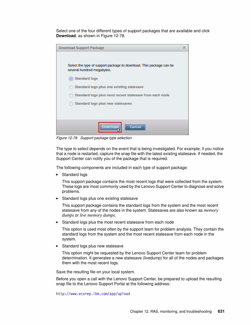
Select one of the four different types of support packages that are available and click Download, as shown in Figure 12-78.
Figure 12-78 Support package type selection
The type to select depends on the event that is being investigated. For example, if you notice that a node is restarted, capture the snap file with the latest existing statesave. If needed, the Support Center can notify you of the package that is required.
The following components are included in each type of support package:
� Standard logs
This support package contains the most recent logs that were collected from the system. These logs are most commonly used by the Lenovo Support Center to diagnose and solve problems.
� Standard logs plus one existing statesave
This support package contains the standard logs from the system and the most recent statesave from any of the nodes in the system. Statesaves are also known as memory dumps or live memory dumps.
� Standard logs plus the most recent statesave from each node
This option is used most often by the support team for problem analysis. They contain the standard logs from the system and the most recent statesave from each node in the system.
� Standard logs plus new statesave
This option might be requested by the Lenovo Support Center team for problem determination. It generates a new statesave (livedump) for all of the nodes and packages them with the most recent logs.
Save the resulting file on your local system.
Before you open a call with the Lenovo Support Center, be prepared to upload the resulting snap file to the Lenovo Support Portal at the following address:
http://www.ecurep.ibm.com/app/upload
Chapter 12. RAS, monitoring, and troubleshooting 631

You can call the Support Line or use the Support Portal to open a call. If you use the latter option, go to the following address:
http://www.ibm.com/support/entry/portal/0pen_service_request?brandind=Hardware
Collecting individual filesThe Support panel also provides access to individual files that are on the node canisters, as shown in Figure 12-79. Click Show full log listing to access the node canister files. To save a file to the user’s workstation, select a file, right-click the file, and select Download. To change to the file listing to show the files on a partner node canister, select the node canister from the menu that is next to the Actions menu.
Figure 12-79 Individual file download
12.8.2 Collecting support information by using the SAT
The Lenovo Storage V3700 V2, V3700 V2 XP, and V5030 management GUI collect information from all of the components in the system. The Service Assistant Tool (SAT) collects information from all node canisters. The snap file is the information that is collected and packaged in a single file.
632 Implementing the Lenovo Storage V3700 V2 and V5030 Systems

If the package is collected by using the Service Assistant Tool, ensure that the node from which the logs are collected is the current node, as shown in Figure 12-80.
Figure 12-80 Accessing the Collect Logs panel in the Service Assistance Tool
Support information can be downloaded with or without the latest statesave, as shown in Figure 12-81.
Figure 12-81 Collect Logs panel in the Service Assistance Tool
Accessing the SAT by using the technician portIf your system or one of your node canisters is inaccessible through the administrative network, you can connect a personal computer directly to the technician port on the node canister to access the Service Assistant Tool.
Note: This procedure starts the initialization tool if the node canister that is being serviced is in the candidate state, if no system details are configured, and if the partner node is not in the active state.
Chapter 12. RAS, monitoring, and troubleshooting 633

Complete the following steps:
1. Configure Dynamic Host Configuration Protocol (DHCP) on the Ethernet port of the personal computer to connect to the node canister.
Alternatively, if the personal computer does not support DHCP, configure the static IPv4 address 192.168.0.2 on the port.
2. On the Lenovo Storage V3700 V2 system or Lenovo Storage V3700 V2 XP system, reenable the technician port by completing the following steps:
a. Create a text file with the satask chserviceip -techport enable -force command.
b. Save the file as satask.txt in the root directory of the Universal Serial Bus (USB) stick.
c. Insert the USB stick in the USB port of the node that you want to service.
d. Wait until no write activity is recognized and remove the USB stick.
3. Connect an Ethernet cable between the port on the personal computer and the technician port. The technician port is labeled with a T on the rear of the node canister.
4. Open a supported web browser on the personal computer and browse to the http://192.168.0.1 URL
5. Complete the correct procedure to service the canister.
6. Log out of the Service Assistant Tool and disconnect the Ethernet cable from the technician port.
7. On the Lenovo Storage V3700 V2 system or Lenovo Storage V3700 V2 XP system, disable the technician port by running the command that is shown in Example 12-3.
Example 12-3 Disabling the technician port
>satask chserviceip -techport disable
SAS port 2 can then be used again to provide extra Ethernet connectivity for system management, iSCSI, and IP replication.
Note: The Lenovo Storage V5030 system has a dedicated technician port that is always enabled so this step is unnecessary.
Note: If the cluster is active and you connect to the configuration node, this URL opens the management GUI. If you want to access the SAT in this case, browse to http://192.168.0.1/service
634 Implementing the Lenovo Storage V3700 V2 and V5030 Systems

12.9 Powering off the system and shutting down the infrastructure
The following sections describe the process to power off the system and to shut down and start an entire infrastructure that contains an Lenovo Storage V3700 V2, V3700 V2 XP, and V5030.
12.9.1 Powering off
You can power off a node canister or the entire system. When you power off only one node canister for each I/O group, all of the running tasks remain active while the remaining node takes over.
Powering off the system is typically planned in site maintenance (power outage, building construction, and so on) because all components of the Lenovo Storage V3700 V2, V3700 V2 XP, and V5030 are redundant and replaceable while the system is running.
Before you power off the system, stop all hosts with volumes that are allocated to this system. This step can be skipped for hosts with volumes that are provisioned with mirroring (host-based mirror) from different storage systems. However, skipping this step means that errors that relate to lost storage paths and disks can be logged on the host error log.
Important: Never power off your Lenovo Storage V3700 V2, V3700 V2 XP, and V5030 systems by powering off the power supply units (PSUs), removing both PSUs, or removing both power cables from a running system. It can lead to inconsistency or loss of the data that is staged in the cache.
Important: If you are powering off the entire system, you lose access to all volumes that are provided by this system. Powering off the system also powers off all Lenovo Storage V3700 V2, V3700 V2 XP, and V5030 nodes. All data is flushed to disk before the power is removed.
Note: If a canister or the system is powered off, a local visit can be required to either reseat the canister or power cycle the enclosures.
Chapter 12. RAS, monitoring, and troubleshooting 635

Powering off a node canisterTo power off a canister by using the GUI, complete the following steps:
1. Browse to Monitoring → System and rotate the enclosure to the rear view, as shown in Figure 12-82.
Figure 12-82 Rotating the system image
2. Right-click the required canister and select Power Off Canister, as shown in Figure 12-83.
Figure 12-83 Powering off the canister
636 Implementing the Lenovo Storage V3700 V2 and V5030 Systems

3. Confirm that you want to power off the canister by entering the confirmation code and clicking OK, as shown in Figure 12-84.
Figure 12-84 Canister power off confirmation window
4. After the node canister is powered off, you can confirm that it is offline in the System panel, as shown in Figure 12-85.
Figure 12-85 Checking the canister state
To power off a node canister by using the CLI, use the command that is shown in Example 12-4.
Example 12-4 Powering off a canister by using the CLI
>svctask stopsystem -node 2Are you sure that you want to continue with the shut down? (y/yes to confirm)
Chapter 12. RAS, monitoring, and troubleshooting 637

Powering off the systemTo power off the entire system by using the GUI, complete the following steps:
1. Browse to Monitoring → System, click Actions → Power Off System, as shown in Figure 12-86.
Figure 12-86 Powering off the system
2. Confirm that you want to power off the system by entering the confirmation code and clicking OK, as shown in Figure 12-87. Ensure that all FlashCopy, Metro Mirror, Global Mirror, data migration operations, and forced deletions are stopped or allowed to complete before you continue.
Figure 12-87 Power Off System confirmation window
638 Implementing the Lenovo Storage V3700 V2 and V5030 Systems

To power off the system by using the CLI, use the command that is shown in Example 12-5. Ensure that all FlashCopy, Metro Mirror, Global Mirror, data migration operations, and forced deletions are stopped or allowed to complete before you continue.
Example 12-5 Powering off the system by using the CLI
>svctask stopsystemAre you sure that you want to continue with the shut down? (y/yes to confirm)
Wait for the power LED on the node canisters to blink slowly, which indicates that the power off operation completed.
12.9.2 Shutting down and starting up the infrastructure
To shut down an entire infrastructure (storage, servers, and applications), complete the following steps:
1. Power off your servers and all applications.
2. Power off your Lenovo Storage V3700 V2, V3700 V2 XP, and V5030 system by using either the GUI or the CLI.
3. Remove the power cords that are connected to both power supplies in the rear of the enclosure on every control and expansion enclosure.
4. Power off your storage area network (SAN) switches.
To start an entire infrastructure, complete the following steps:
1. Power on your SAN switches and wait until the boot completes.
2. Power on any expansion enclosures by connecting the power cord to both power supplies in the rear of the enclosure or by turning on the power circuit.
3. Power on the control enclosures by connecting the power cords to both power supplies in the rear of the enclosure and by turning on the power circuits.
The system starts. The system starts successfully when the status LEDs of all node canisters in the control enclosure are permanently on, which takes no longer than 10 minutes.
Power on your servers and start all applications.
Note: When you power off an Lenovo Storage V3700 V2, V3700 V2 XP, and V5030, they do not automatically restart. You must manually restart the system by removing and reapplying the power.
Chapter 12. RAS, monitoring, and troubleshooting 639

640 Implementing the Lenovo Storage V3700 V2 and V5030 Systems

Chapter 13. Encryption
Encryption protects against the potential exposure of sensitive user data that is stored on discarded, lost, or stolen storage devices. The Lenovo Storage V5030 supports optional encryption of data at rest, and an encryption license for each enclosure is required.
Two main encryption methods can be implemented in the Lenovo Storage V5030:
� Hardware encryption that is used for serial-attached Small Computer System Interface (SCSI) (SAS) internal storage, for example, an expansion enclosure
� Software encryption that is used for external, virtualized storage
This chapter includes the following topics:
� 13.1, “Introducing encryption” on page 642� 13.2, “Defining encryption of data at rest” on page 642� 13.3, “Activating encryption” on page 648� 13.4, “Enabling encryption” on page 664� 13.5, “Using encryption” on page 673� 13.6, “Creating pools and adding internal storage” on page 676� 13.7, “Creating a software-encrypted external pool” on page 680� 13.8, “Encrypting volumes” on page 685� 13.9, “Encrypting pools and child pools” on page 689� 13.10, “Migrating unencrypted pools and arrays” on page 691� 13.11, “Rekeying an encryption-enabled system” on page 697� 13.12, “Disabling encryption” on page 700� 13.13, “Using CLI commands for encryption” on page 702
13
© Copyright Lenovo 2018. All rights reserved. 641

The encryption support depends on the Lenovo Storage V3700 V2, V3700 V2 XP, and V5030 model, as shown in Table 13-1.
Table 13-1 Lenovo Storage V3700 V2, V3700 V2 XP, and V5030 encryption support
13.1 Introducing encryption
First, we define the encryption types:
� Hardware encryption: SAS hardware encryption is specific to the Lenovo Storage V5030 hardware. After encryption is enabled, all internal storage array objects are created as hardware that is encrypted, by default. Hardware is encrypted within the SAS chip, and the hardware encryption does not consume any additional resources.
� Software encryption: Software encryption is specific to the Lenovo Storage V5030, and the software is encrypted on external, attached storage at the pool level. Software encryption uses the CPU and the AES_NI CPU instruction set and engines. The Lenovo Storage V5030 provides six cores for each node, and they are all used for encryption. Each core contains up to 1 GBps (6 GBps for each node and 12 GBps for each I/O group). If compression is enabled, four out of six cores are dedicated to compression, so only two cores on the CPU are used for encryption (2 GBps for each node and 4 GBps for each I/O group).
Both methods of encryption protect against the potential exposure of sensitive user data and user metadata that are stored on discarded, lost, or stolen storage devices. Both methods of encryption can also facilitate the warranty return or disposal of hardware.
Both methods of encryption use the same encryption algorithm, the same key management. And, they use the same license.
Selection of the encryption method is fully transparent. The Lenovo Storage V5030 uses hardware encryption for internal SAS-attached disks. External disks are encrypted by software. The encryption method must not be selected manually.
13.2 Defining encryption of data at rest
Encryption is the process of encoding data so that only authorized parties can read it. Secret keys are used to encode the data according to well-known algorithms.
SAS hardware encryption Software encryption
Lenovo Storage V5030 Yes Yes
Lenovo Storage V3700 V2 XP No No
Lenovo Storage V3700 V2 No No
IBM Storwize V5000 for Lenovo No No
Note: The design for encryption is based on the concept that a system must either be encrypted or not encrypted. By implementing encryption, we chose not to provide a solution that contained both encrypted volumes and unencrypted volumes. However, environments can exist where you enable encryption on encryption-capable systems with pre-existing unencrypted volumes.
642 Implementing the Lenovo Storage V3700 V2 and V5030 Systems

Encryption of data at rest is defined by the following characteristics:
� “Data at rest” means that the data is encrypted on the end device (drives).
� The algorithm that is used is the Advanced Encryption Standard (AES) US government standard from 2001.
� Encryption of data at rest complies with the Federal Information Processing Standard 140 (FIPS-140) standard, but it not certified.
� Ciphertext stealing (XTS)-AES 256 is used for data keys.
� AES 256 is used for master keys.
� The algorithm is public. The only secrets are the keys.
� The symmetric key algorithm is used. (The same key used to encrypt and decrypt data.)
The encryption of system data and the encryption of system metadata are not required, so system data and metadata are not encrypted.
Encryption is enabled at a system level and all of the following prerequisites must be met before you can use encryption:
� You must purchase an encryption license before you activate the function.
If you did not purchase a license, contact an LenovoSales representative or Lenovo Business Partner to purchase an encryption license.
� At least three USB flash drives are required before encryption enablement. They are available as a feature code from Lenovo.
� You must activate the license that you purchased.
� Encryption must be enabled.
After encryption prerequisites are met and encryption is enabled successfully, you can turn on hardware encryption, by default, for all internal arrays that are created.
Encryption for data at rest is full data encryption on data storage (that is, at the storage system). Host to storage communication and Remote Mirroring are not encrypted.
Figure 13-1 on page 644 shows an encryption example. Encrypted disks and encrypted data paths are marked in blue. Unencrypted disks and data paths are marked in red. The server sends unencrypted data to the Lenovo Storage V5030, which stores hardware-encrypted data on internal disks. The data is mirrored to a Lenovo Storage V3700 V2 by using Remote Mirroring. The data is not encrypted during replication. Because the Lenovo Storage V3700 V2 is unable to perform any encryption activities, data on the Lenovo Storage V3700 V2 is not encrypted.
Chapter 13. Encryption 643

Figure 13-1 Hardware encryption example
If both data copies must be encrypted, the Lenovo Storage V3700 V2 must be replaced by a Lenovo Storage V5030, including the correct licenses, as shown in Figure 13-2. Although both copies are encrypted, the Remote Mirror between both sites is still not encrypted.
Figure 13-2 Hardware encryption and Remote Mirror
Figure 13-3 shows an example for software and hardware encryption. Software encryption is used to encrypt an external virtualized storage system. Hardware encryption is used for internal, SAS-attached disk drives.
Figure 13-3 Example of software encryption and hardware encryption
V5030
V5030
644 Implementing the Lenovo Storage V3700 V2 and V5030 Systems

Hardware encryption and software encryption in the Lenovo Storage code stack are shown in Figure 13-4. The functions that are implemented in software are shown in blue. The external storage system is shown in yellow. The hardware encryption on the SAS chip is marked in pink. The following information refers to Figure 13-4:
� Compression is performed “before” encryption. Therefore, both compression and encryption can be applied to the same data.
� Hardware encryption is performed by the SAS hardware. Therefore, encryption works only with internal drives, which are configured as an array of disks.
� You must decide whether to encrypt or not encrypt a hardware-encrypted object (array) when you create the object. You cannot change it after you create the object.
� If hardware encryption is enabled, all SAS-attached arrays (encrypted and unencrypted) are not accessible after a cold boot until the master access key is available.
Figure 13-4 Encryption in the software stack
Each volume copy can use different encryption types (hardware, software, or no encryption). The encryption type depends on the pool that is used for the specific copy. You can migrate data between different encryption types by using volume migration or volume mirroring.
Chapter 13. Encryption 645

13.2.1 Encryption keys
Hardware and software encryption use the same encryption key technology. The only difference is the object that is encrypted by using the keys. The following objects are used:
� Arrays (hardware encryption)� Managed disks (software encryption)� Pools (software encryption)� Child pools (software encryption)
Encryption keys are described:
� The encryption keys are unique keys for each object, and they are created when the object is created. The creation of multiple keys is possible.
� Two types of keys are available:
– Master access key (one for each system):
• The master access key is created when encryption is enabled.
• The master access key is stored on USB devices when encryption is enabled.
• It can be copied or backed up as necessary.
• It is not stored in the Cluster Systems Management (CSM) memory or any other non-volatile storage on the cluster.
– Data encryption key (one for each encrypted object):
• The data encryption key is used to encrypt data. It is created automatically when an encrypted object, such as an array, a managed disk (MDisk), or a pool, is created.
• It is stored in secure memory.
• The data encryption key is encrypted with the master key during cluster internal communication.
• No way exists to view the data encryption key.
• The data encryption key cannot be changed.
• It is discarded when an array is deleted (secure erase).
Note: After encryption in the enclosure is enabled, all new build arrays are hardware encrypted, by default. The graphical user interface (GUI) supports only this default. However, you can create an unencrypted array by using the command-line interface (CLI) and by using the mkarray -encrypt no command.
To unencrypt an encrypted internal array, you need to migrate its extents to an unencrypted system or to a pool that consists of arrays that were created with hardware encryption that was disabled.
Important: If all keys are lost and the system must cold reboot, all data is gone. No method exists, even for Lenovo, to decrypt the data without the keys. If the system cannot access the master key, all SAS hardware is offline, including unencrypted arrays.
646 Implementing the Lenovo Storage V3700 V2 and V5030 Systems

13.2.2 Encryption licenses
Encryption is akey-based licensed feature. A license must be present for each Lenovo Storage V5030 control enclosure before you enable encryption. Attempts to add a control enclosure can fail if the control enclosure does not have the correct license.
No trial licenses for encryption exist. When the trial runs out, the access to the data is lost. Therefore, you must purchase an encryption license before you activate encryption.
Contact your Lenovo marketing representative or Lenovo Business Partner to purchase an encryption license.
During the initial system setup, you are prompted to activate the license on the system. Or, after the initial setup, you can activate the license in the running environment. License activation cannot enable encryption on the system. Additional activation steps and three USB flash drives are required to enable encryption.
The USB keys, which are required before encryption can be enabled, are available as a feature code from Lenovo.
You can add licenses to the system for enclosures that are not part of the system. Licenses are generated by DSFA and based on the serial number (S/N) and the machine type and model number (MTM) of the enclosure. For more information, see this website:
https://www.ibm.com/storage/dsfa/storwize/selectMachine.wss
On the Lenovo Storage V5030, the license is stored in the midplane. So, it is persistent, but it is not necessarily enabled.
Important: Two different methods are available to activate and enable the Encryption feature. You can use either method to activate an encryption-capable system:
� Use an activation code during the license activation. This automatic activation requires that the personal computer that is used to activate the license is connected to an external network.
� Use a license key that is obtained from the Data storage feature activation (DSFA) web support page:
https://www.ibm.com/storage/dsfa
A license key that is obtained from this site can be used manually during the license activation, if the automatic setup fails, or when encryption is purchased after the system setup is complete.
Note: The system needs at least three USB flash drives that are present before you enable either hardware or software encryption. We recommend Lenovo USB devices, although Lenovo USB devices are not required.
Order the three Lenovo USB devices in eConfig as Feature Code ACEA: Encryption USB Flash Drives (Four Pack).
Chapter 13. Encryption 647

13.3 Activating encryption
Multiple steps are required for encryption enablement at a system level:
1. You must purchase an encryption license first. 2. The purchased license must be activated.3. Encryption must be enabled.
Activation of the license can be performed in one of two ways, either automatically or manually. The two methods of activating the license are during the initial system setup and in the running system.
The next three sections of the chapter guide you through the process of obtaining a license, activating a license, and enabling the hardware encryption, ensuring that all prerequisites are met. We use examples of activating encryption during the initial system setup mode and activating encryption during the normal mode of operation.
13.3.1 Obtaining an encryption license
You must purchase an encryption license before you activate the function. If you did not purchase a license, contact an Lenovo marketing representative or Lenovo Business Partner to purchase an Encryption license. Ensure that the following information is available:
� Machine type and model (MTM)� Serial number (S/N)� Machine signature
Licenses are generated by DSFA. They are based on the serial number/MTM. To enable a system, at least three USB flash drives must be present:
https://www.ibm.com/storage/dsfa/storwize/selectMachine.wss
We recommend Lenovo USB devices, although Lenovo USB devices are not required. Order the Lenovo USB devices: Encryption USB Flash Drives (Four Pack).
13.3.2 Activating an encryption license
You can activate encryption either at installation by using the initial system setup or later on a running system by using the System Licensed Functions page. Both methods use the same procedures. In either scenario, you can choose to activate the license automatically or manually.
648 Implementing the Lenovo Storage V3700 V2 and V5030 Systems

Activate the license manually during the initial system setup The fourth stage of the system setup process relates to the encryption setup. The system asks “Was the encryption feature purchased for this system?” You reply with either No or Yes, as shown in Figure 13-5.
Figure 13-5 Encryption activation during the system setup
By selecting Yes, the Encryption panel, as shown in Figure 13-6, displays information about your local machine.
Figure 13-6 Information panel of the local machine
Chapter 13. Encryption 649
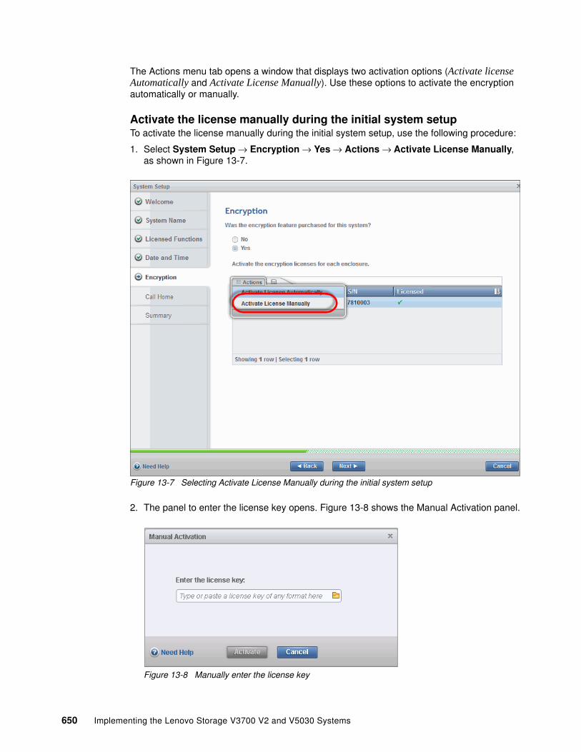
The Actions menu tab opens a window that displays two activation options (Activate license Automatically and Activate License Manually). Use these options to activate the encryption automatically or manually.
Activate the license manually during the initial system setupTo activate the license manually during the initial system setup, use the following procedure:
1. Select System Setup → Encryption → Yes → Actions → Activate License Manually, as shown in Figure 13-7.
Figure 13-7 Selecting Activate License Manually during the initial system setup
2. The panel to enter the license key opens. Figure 13-8 shows the Manual Activation panel.
Figure 13-8 Manually enter the license key
650 Implementing the Lenovo Storage V3700 V2 and V5030 Systems

3. You can enter the license key either by typing it or by using cut or copy and paste. In Figure 13-9, the sample key is already entered. Click Activate.
Figure 13-9 License key was entered
4. Figure 13-10 shows the completion of the activation process.
Figure 13-10 Completing the activation process
Chapter 13. Encryption 651

5. Confirmation that encryption was activated is indicated by the green check mark under the Licensed heading, as shown in Figure 13-11.
Figure 13-11 Encryption was activated
Activate the license automatically during the initial system setupIn this section, we show how to activate encryption automatically by using the System Setup menu. Start with the Encryption section of the System Setup window.
652 Implementing the Lenovo Storage V3700 V2 and V5030 Systems

Follow these steps:
1. Select an enclosure and click Actions. Select Activate License Automatically. Figure 13-12 shows how to start the automatic activation.
Figure 13-12 Activate encryption automatically
2. Click Next. Figure 13-13 shows the field to enter the license key (purchased authorization code).
Figure 13-13 Enter the authorization code
Important: To perform this operation, the personal computer that is used to activate the license must connect to an external network.
Chapter 13. Encryption 653

3. Enter the authorization code that is specific to the enclosure that you selected, as shown in Figure 13-14.
Figure 13-14 Sample authorization code
4. After you enter the authorization code, click Activate. Figure 13-15 shows the commands that are executed to activate the feature license key.
Figure 13-15 Activating encryption
Note: The authorization code is sent with the licensed function authorization documents. These documents contain the authorization codes that are required to obtain keys for each licensed function that you purchased for your system.
For any problems, contact your Lenovo marketing representative or Lenovo Business Partner.
654 Implementing the Lenovo Storage V3700 V2 and V5030 Systems

5. After the activatefeature command is executed, the system connects to IBM to verify the authorization code, retrieve the license keys, and apply them. Figure 13-16 shows this connection. If everything works correctly, the procedure takes less than a minute.
Figure 13-16 Sending machine information to IBM
6. When encryption is successfully enabled, you see the green check mark under the heading that is labeled Licensed, as shown in Figure 13-17.
Figure 13-17 Successful activation of the Encryption feature
The encryption section of the system setup is complete.
Chapter 13. Encryption 655

Problems with automatic license activation If problems occur with the activation procedure, the Lenovo Storage V5030 times out after 2.5 minutes, as shown in Figure 13-18.
Check whether your activation code (not license) is a valid activation code. Check whether you can access the internet or whether you are experiencing any problems with the Lenovo Storage V5030. If this activation procedure still does not work, try to use the manual activation procedure, which was described earlier. For the manual activation procedure, you need a valid encryption license key.
Figure 13-18 No connection was possible
Activate the license manually on a running systemLicense activation on the running system is available at the Settings menu. Follow these steps:
1. Open System → Licensed Functions → Encryption Licenses, as shown in Figure 13-19.
Figure 13-19 Selecting Encryption Licenses on the System Licensed Functions page
656 Implementing the Lenovo Storage V3700 V2 and V5030 Systems
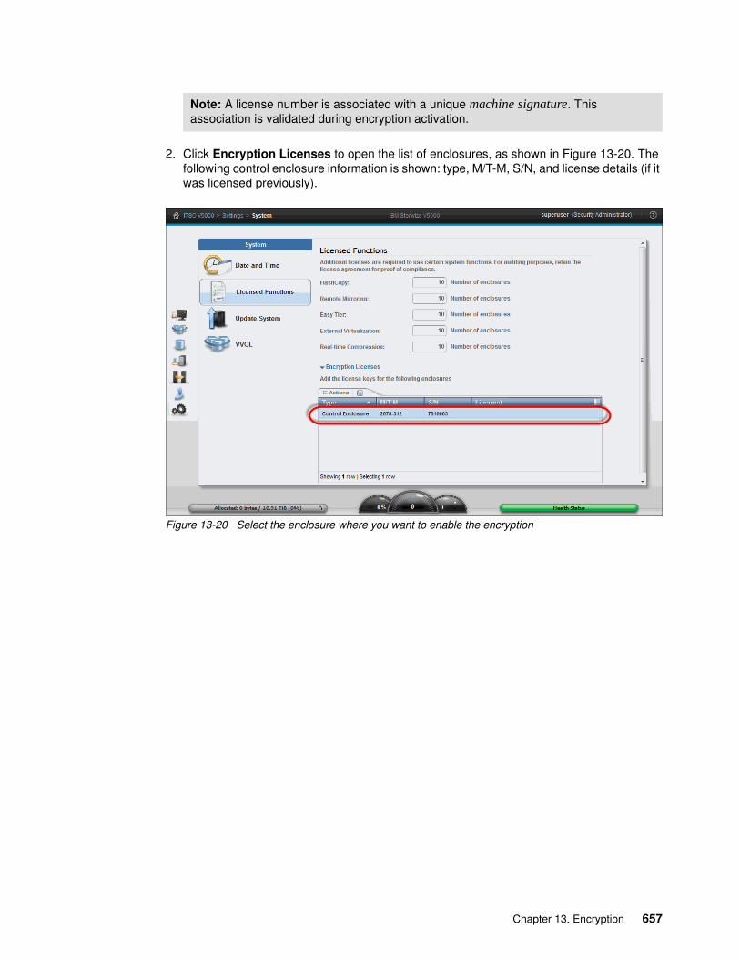
2. Click Encryption Licenses to open the list of enclosures, as shown in Figure 13-20. The following control enclosure information is shown: type, M/T-M, S/N, and license details (if it was licensed previously).
Figure 13-20 Select the enclosure where you want to enable the encryption
Note: A license number is associated with a unique machine signature. This association is validated during encryption activation.
Chapter 13. Encryption 657

3. Select a control enclosure and click Actions → Activate License Manually, as shown in Figure 13-21.
Figure 13-21 Activate the encryption license manually
4. The Manual Activation window opens, as shown in Figure 13-22.
Figure 13-22 Manual Activation window
658 Implementing the Lenovo Storage V3700 V2 and V5030 Systems

5. Enter the encryption license key as shown in Figure 13-23.
Figure 13-23 Enter the license key
6. Press Activate and the completion confirmation displays (Figure 13-24).
Figure 13-24 License activation is complete
Chapter 13. Encryption 659

7. Verify that the license was activated (but not enabled). Click System → Licensed Functions → Encryption Licenses. The drop-down list shows the control enclosure information and the green check mark indicates an active license, as shown in Figure 13-25.
Figure 13-25 An activated license is indicated with a green check mark
Activate the license automatically on a running systemFollow these steps to activate the license automatically on a running system:
1. Navigate to the System menu. Select System → Licensed Functions. Click Encryption Licenses to show the drop-down list. Click Actions. Select Activate License Automatically, as shown in Figure 13-26.
Figure 13-26 Activate the encryption license automatically on a running system
660 Implementing the Lenovo Storage V3700 V2 and V5030 Systems

2. Enter the authorization code that is specific to the enclosure that you selected, as shown in Figure 13-27.
Figure 13-27 Sample of an authorization code
3. After you enter the authorization code, click Activate. Figure 13-28 shows the commands that were executed to activate the feature license key.
Figure 13-28 Activating encryption
Note: The authorization code is sent with the licensed function authorization documents. These documents contain the authorization codes that are required to obtain keys for each licensed function that you purchased for your system.
For any problems, contact your Lenovo marketing representative or Lenovo Business Partner.
Chapter 13. Encryption 661

4. After the activatefeature command executes, the system connects to IBM to verify the authorization code, retrieve the license keys, and apply them. Figure 13-29 shows the connection. If the process works correctly, the procedure takes less than a minute.
Figure 13-29 Sending the machine information to IBM
5. When the encryption is successfully enabled, you see the green check mark under the Licensed heading, as shown in Figure 13-30.
Figure 13-30 Confirmation that the encryption license is active
662 Implementing the Lenovo Storage V3700 V2 and V5030 Systems

Error messages and additional guidance You might use multiple licenses and activation codes. If you need to cross-reference control enclosure and license information, click System → Licensed Functions → Encryption Licenses. Click Encryption Licenses, highlight your enclosure, and select Manual Activation. In the Manual Activation panel, click Need Help. A panel opens that displays the machine signature, as shown in Figure 13-31.
Figure 13-31 Machine signature
Error messages Although authorization codes and encryption licenses use the same 4 x 4-digit format, you can use them only in specific modes of activation. If you use a license key when the system expects an authorization code, the error message that is shown in Figure 13-32 appears.
Figure 13-32 Authorization code failure
Chapter 13. Encryption 663

13.4 Enabling encryption
In this section, we describe the concept of encryption keys. We explain that these encryption keys are stored on USB flash drives that connect to the Lenovo Storage V5030.
Physical access to systems with a single I/O group is required during the enablement process for physical key replacement.
13.4.1 Introduction to encryption enablement
If the license activation passes all of the required steps, you need to enable encryption. Encryption enablement is performed outside of the initial system setup by using the Enable Encryption wizard, which is available in the GUI. The same steps can be performed by using the CLI.
The process requires three USB flash drives to store the generated master access key. The Lenovo Storage V5030 provides a single USB slot in each node canister, so two USB slots are available in a control enclosure. The master access key must be created on at least three USB flash drives during the enabling process, so the USB flash drives must be changed during the enablement process. A minimum of one USB flash drive with the correct master access key is required to enable encryption for the cluster after the cold boot.
If your system is in a secure location, one USB flash drive for each canister can remain inserted in the system. If the location is not secure, all USB flash drives with the master access keys need to be removed from the system and be stored securely. The data center power-on procedure needs to include instructions about the USB flash drive locations and how to use them.
The USB flash drive is not required during a warm reboot, such as a service mode or canister reboot, but it is required after a power loss (cold boot).
You are required to insert three USB flash drives into the canisters to enable encryption and to rekey the system. During these operations, you are responsible for ensuring the security of the system.
During power-on, we recommend that you insert USB flash drives into the USB ports on two supported canisters to guard against any unexpected failure of the node, the node’s USB port, or the USB flash drive during the power-on procedure. Use these general guidelines when you enable encryption and manage the USB flash drives that contain encryption keys.
While the system enables encryption, you are prompted to insert the USB flash drives into the system. The system copies the encryption keys to these drives systematically. The system generates and copies the encryption keys to all available USB flash drives.
Important: You cannot enable encryption until the prerequisite of a minimum of three USB flash drives are installed.
Important: When you remove all USB flash drives, the system is not able to access the encrypted data after a cold boot. You must insert at least one USB flash drive with the actual encryption key, so remember this important step if you want to avoid delays.
664 Implementing the Lenovo Storage V3700 V2 and V5030 Systems

Securely store all copies of the encryption key. For example, any USB flash drives that are not left inserted into the system can be locked in a safe. Comparable precautions must be taken to securely protect any other copies of the encryption key that are stored in other forms of storage.
Figure 13-33 shows the wizard, which appears after the successful activation of encryption during the initial system setup.
Figure 13-33 Suggested task after the initial system setup
Or, click Security → Encryption → Enable Encryption, as shown in Figure 13-34.
Figure 13-34 Enable Encryption from the Security window
Notes: In addition to the copies that are generated on the USB flash drives when encryption is enabled on the system, create at least one additional copy on another USB flash drive and store it in a secure location. Copy the encryption keys to other forms of storage to provide resiliency and to mitigate risk if, for example, the USB flash drives are from a faulty batch of drives.
Ensure that each copy of the encryption key is valid before you write any user data to the system. The system validates any key material on a USB flash drive when it is inserted into the canister. If the key material is not valid, the system logs an error. If the USB flash drive is unusable or fails, the system does not display it as output.
Chapter 13. Encryption 665

Follow these steps:
1. Click Enable Encryption to start the wizard, as shown in Figure 13-35.
Figure 13-35 Enable Encryption wizard
The Welcome window highlights that a minimum of three USB flash drives are required before encryption can be enabled.
666 Implementing the Lenovo Storage V3700 V2 and V5030 Systems

2. Insert the first two USB flash drives, and then click Next, or simply click Next without inserting the first two USB flash drives. Either option opens the USB Flash Drives window, as shown in Figure 13-36.
Figure 13-36 Insert the first two USB flash drives
The USB Flash Drives window indicates the number of required USB flash drives and also provides status about the number of USB flash drives that are detected.
In the example in Figure 13-36, zero out of a minimum of three encryption keys are detected.
3. Insert the USB flash drives into the USB ports.
Note: The Next option remains disabled until two USB flash drives are detected.
Chapter 13. Encryption 667

4. The system recognizes and reports the number of USB flash drives that are inserted. In the example, two USB flash drives are detected, as shown in Figure 13-37.
Figure 13-37 Writing the master access key to two of the three USB flash drives
5. After the minimum requirement is met, the encryption keys are automatically copied on the USB flash drives, as shown in Figure 13-38. We used the first two USB flash drives. At least one of them must be replaced with a new USB flash drive.
Figure 13-38 Replace one encryption key and write the third key
668 Implementing the Lenovo Storage V3700 V2 and V5030 Systems

6. When the process completes, the panel that is shown in Figure 13-39 appears.
Figure 13-39 Encryption key creation was completed
The USB flash drive icon is turquoise, and the Next option is active. An “Encryption keys copied to USB flash drives (or created)” message is displayed. Click Show details.
7. As shown in Figure 13-40, two keys are inserted, prepared, and ready to use. If one USB flash drive fails, it is not shown. Click Next to take you to the Summary panel.
Figure 13-40 Overview of the USB flash drives in the detailed view
Chapter 13. Encryption 669

8. Pools that exist but that are not encrypted are shown, as shown in Figure 13-41. Click Commit to finalize the encryption enablement.
Figure 13-41 Commit the encryption enablement
9. Encryption is enabled, as shown in Figure 13-42.
Figure 13-42 Encryption is enabled
670 Implementing the Lenovo Storage V3700 V2 and V5030 Systems

Verification of an encryption-enabled system Click Settings → Security → Encryption to confirm that encryption is enabled and that the encryption state is ON, as shown in Figure 13-43.
Figure 13-43 Confirmation of enabled encryption
Also, the audit log indicates that encryption is enabled. Figure 13-44 shows the entry for enabling encryption in the audit log.
Figure 13-44 Audit log
Chapter 13. Encryption 671

To verify the correct installation of encryption, click Settings → Security → Encryption to show “2 USB Flash Drives Detected”. By clicking 2 USB Flash Drives Detected, you open the detailed list and show the state, which is Validated, of your USB flash drives (Figure 13-45).
Figure 13-45 Details about the two USB flash drives
Ensure that each copy of the encryption key is valid before you write any user data to the system. The system validates any key material on a USB flash drive when it is inserted into the canister. If the key material is not valid, the system logs an error. If the USB flash drive is not usable or fails, the system cannot display it as an output.
Figure 13-46 shows the contents of a valid entry of a USB encryption flash drive.
Figure 13-46 Content of the encryption USB flash drive
For each canister on the system, you can leave the USB flash drives inserted into the system. However, the area where the system exists must be secure to prevent the loss or theft of the keys. If the area where the system exists is not secure, remove all of the USB flash drives from the system and store them securely.
Important: In addition to the copies that are generated on the USB flash drives when encryption is enabled on the system, create at least one additional copy on another USB flash drive and store this USB flash drive in a secure location.
672 Implementing the Lenovo Storage V3700 V2 and V5030 Systems

Figure 13-47 shows the Encryption panel when no valid USB flash drive is inserted.
Figure 13-47 No USB flash drive is inserted
13.5 Using encryption
The design for encryption is based on the concept that a system must either encrypt or not. The Lenovo Storage solution is not intended to present both encrypted volumes and unencrypted volumes. Code policies are designed to prevent partial encryption. For example, no support exists for creating unencrypted child pools from encrypted parent pools. However, exceptions exist:
� Distributed RAID cannot support hardware encryption.
� During the migration (conversion) of volumes from unencrypted to encrypted volumes, a system might report both encrypted and unencrypted volumes.
� Traditional RAID (TRAID), which is created by using the CLI, where the client intentionally overrides the encryption default.
If you use the Lenovo Storage V5030 to manage external storage pools, you can apply software encryption at a storage pool layer. MDisks that are added to an encrypted pool can, by default, become encrypted by using software encryption. The following exceptions to this rule exist:
� If an external MDisk is detected as self-encrypting� If an external MDisk is declared as self-encrypting
Note: Where possible, the Lenovo Storage V5030 hardware default to the use of hardware encryption because no CPU overhead exists. We suggest that you encrypt all volumes after you enable encryption.
No option exists in the GUI to create unencrypted arrays, but you can override this default by using the CLI by running the mkarray -encrypt no command.
Chapter 13. Encryption 673

You can mix and match encryption types in a pool. The graphic that is shown in Figure 13-48 provides guidance.
Figure 13-48 Mix and match encryption MDisks
13.5.1 Encryption
The Lenovo Storage V5030 hardware encryption continues to be the only encryption method for internal drives and arrays. Storage pools that consist of only internal arrays (MDisks) do not have a specific hardware encryption attribute. They are encrypted as a consequence of the MDisk extents that they contain.
674 Implementing the Lenovo Storage V3700 V2 and V5030 Systems

You can check the hardware encryption state of the arrays (MDisks) and drives by selecting Pools → Internal Storage. When you create the array by using the GUI, the associated internal drives are assigned an encrypted property, as shown in Figure 13-49.
By enabling Encrypted in the Filter bar, the Encrypted heading indicates whether drives are encrypted. All drives with a property member (configured into a RAID array (MDisk)) are marked with green encryption check marks. All other non-member drives show no designation under this heading.
Figure 13-49 View of the encrypted MDisks under internal storage
By clicking Pools → MDisk by Pools and by enabling Encrypted in the Filter bar, the encryption characteristics at the pool and MDisk levels display, as shown in Figure 13-50. A pool of assigned internal storage from a hardware-encrypted array inherits the hardware-encrypted state from the MDisks that it contains.
Figure 13-50 A pool inherits the hardware-encrypted state from the MDisks that it contains
Chapter 13. Encryption 675

13.6 Creating pools and adding internal storage
The type of encryption that your system uses might not be obvious. The most important consideration is whether the system uses encryption or not. Consider a newly configured system that is encryption-enabled.
The Suggested Task menu leads you through the procedure to create pools, as shown in Figure 13-51.
Figure 13-51 Suggested Task: Create Pools
Follow these steps:
1. Select Create Pools to open the Create Pool window, as shown in Figure 13-52.
Figure 13-52 Create Pool window with a name field and an option to enable encryption
2. Because encryption is enabled at a system level, this panel defaults to Encryption Enable. Enter a name for the pool. Leave Encryption Enable selected, and select Create.
676 Implementing the Lenovo Storage V3700 V2 and V5030 Systems

3. The Task completed message is displayed, as shown in Figure 13-53.
Figure 13-53 Create an encrypted pool
The svctask mkmdiskgrp command shows that the pool is created with encryption as a default.
4. The next suggested task is to create arrays, as shown in Figure 13-54.
Figure 13-54 Create internal arrays
Note: Before you configure an array from internal drives, you must configure the internal drives as candidates.
Chapter 13. Encryption 677

5. Use the Assign Storage to Pool window to configure an array to add to your storage pool. In this example, we chose to create an array by using the Quick Internal option and by using two drives from the Nearline drive class and a RAID configuration, as shown in Figure 13-55. Select Assign.
Figure 13-55 Create an internal array and assign the array to the pool
678 Implementing the Lenovo Storage V3700 V2 and V5030 Systems
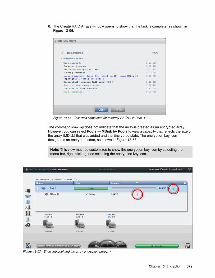
6. The Create RAID Arrays window opens to show that the task is complete, as shown in Figure 13-56.
Figure 13-56 Task was completed for mkarray RAID10 in Pool_1
The command mkarray does not indicate that the array is created as an encrypted array. However, you can select Pools → MDisk by Pools to view a capacity that reflects the size of the array (MDisk) that was added and the Encrypted state. The encryption key icon designates an encrypted state, as shown in Figure 13-57.
Figure 13-57 Show the pool and the array encryption property
Note: This view must be customized to show the encryption key icon by selecting the menu bar, right-clicking, and selecting the encryption key icon.
Chapter 13. Encryption 679

Figure 13-57 on page 679 shows an encrypted MDisk key and an encrypted pool key. Both designations indicate that encryption is enabled.
13.7 Creating a software-encrypted external pool
Software encryption can encrypt external storage logical unit numbers (LUNs).
For example, consider a Lenovo Storage V5030 system with a combination of hardware-encrypted pools and unencrypted pools by using external (not self-encrypted) MDisks. This example contains the following combination:
� An external Lenovo Storage V3700 V2, V3700 V2 XP, and V5030 that provide unencrypted storage as MDisks to the Lenovo Storage V5030
� A Lenovo Storage V5030, which encrypts hardware and software and uses hardware-encrypted storage pools with internal disks
The Lenovo Storage V5030 must be used to encrypt the MDisks that are provided from the Lenovo Storage V5030 in a software-encrypted pool.
Follow these steps:
1. From the Lenovo Storage V5030 MDisk by Pools or Pools view, select Create Pool, as shown in Figure 13-58.
Figure 13-58 Create an empty encrypted pool
2. Enter the name of the pool that you want to create. Select Encryption Enable. Click Create.
Note: You can create a software-encrypted pool when you create the pool.
Note: An encryption-enabled system shows the Encryption Enable or Disable option.
680 Implementing the Lenovo Storage V3700 V2 and V5030 Systems

3. The command mkmdiskgrp with the encrypt yes parameter executes, as shown in Figure 13-59.
Figure 13-59 Creating an empty encrypted pool
4. Also, you can display the pool that was created by selecting the MDisk by Pools view. The pool state is Online, No Storage, No Capacity, or Encrypted (Figure 13-60).
Figure 13-60 Confirmation of empty encrypted pool
Chapter 13. Encryption 681

5. You must assign storage (LUNs) to the pool. From the MDisk by Pools view, click Add Storage, which opens the Assign Storage to Pool window.
Use this view to assign MDisks to the selected pool. Follow these steps:
a. Select the Quick External option. Use the Storage system list box to select the storage system. Use the MDisks list box to select the MDisks that you want to assign to your software-encrypted pool, as shown in Figure 13-61.
Figure 13-61 Select the MDisks
682 Implementing the Lenovo Storage V3700 V2 and V5030 Systems

b. Select the MDisk tier level (Flash, Enterprise, or Nearline), as shown in Figure 13-62.
Figure 13-62 Select the MDisk tier level
c. Ensure that the Externally Encrypted check box is not selected if the MDisk is not encrypted, as shown in Figure 13-63.
Figure 13-63 Clear the externally encrypted encryption status of the external MDisk
Chapter 13. Encryption 683
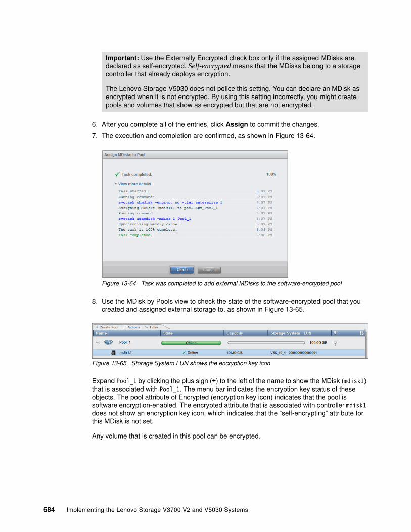
6. After you complete all of the entries, click Assign to commit the changes.
7. The execution and completion are confirmed, as shown in Figure 13-64.
Figure 13-64 Task was completed to add external MDisks to the software-encrypted pool
8. Use the MDisk by Pools view to check the state of the software-encrypted pool that you created and assigned external storage to, as shown in Figure 13-65.
Figure 13-65 Storage System LUN shows the encryption key icon
Expand Pool_1 by clicking the plus sign (+) to the left of the name to show the MDisk (mdisk1) that is associated with Pool_1. The menu bar indicates the encryption key status of these objects. The pool attribute of Encrypted (encryption key icon) indicates that the pool is software encryption-enabled. The encrypted attribute that is associated with controller mdisk1 does not show an encryption key icon, which indicates that the “self-encrypting” attribute for this MDisk is not set.
Any volume that is created in this pool can be encrypted.
Important: Use the Externally Encrypted check box only if the assigned MDisks are declared as self-encrypted. Self-encrypted means that the MDisks belong to a storage controller that already deploys encryption.
The Lenovo Storage V5030 does not police this setting. You can declare an MDisk as encrypted when it is not encrypted. By using this setting incorrectly, you might create pools and volumes that show as encrypted but that are not encrypted.
684 Implementing the Lenovo Storage V3700 V2 and V5030 Systems

13.8 Encrypting volumes
The encryption status of a volume depends on the pool encryption status. An encrypted volume can be created in an encrypted pool only. An unencrypted volume is made out of an unencrypted pool.
13.8.1 Create encrypted volumes
For new volumes, the simplest way to create an encrypted volume is to create it in an encrypted pool, as shown in Figure 13-66. All volumes that are created in an encrypted pool can take an encrypted attribute. The encryption attribute is independent of the volume class that was created.
Figure 13-66 Create a volume and select an encrypted pool
The volume encryption property (encryption key icon) is visible in the GUI, as shown in Figure 13-67.
Figure 13-67 Volume encryption property
Chapter 13. Encryption 685

13.8.2 Volume migration methods
You cannot change an existing volume to an encrypted version of itself dynamically. However, this conversion is possible by using migration techniques. Several scenarios are described.
Scenarios Consider the following scenarios on the Lenovo Storage V3700 V2, V3700 V2 XP, and V5030 hardware:
� Volumes that are created from internal storage pools with extents from arrays that were created before the hardware encryption enablement or arrays that were created with encryption turned off.
� Volumes that were created in external storage pools (not encrypted by an external controller).
You can migrate these volumes into the following types of pools:
� A pool of external storage LUNs (software encryption)� A pool of internal SAS-encrypted arrays (hardware encryption)� A pool that is a mixture of external storage LUNS and internal SAS-encrypted arrays
Volume migration to encrypted storage poolsYou can convert unencrypted volumes to encrypted volumes by selecting the volume, right-clicking, and selecting Migrate to Another Pool, as shown in Figure 13-68.
Figure 13-68 Migrate a volume to another pool
686 Implementing the Lenovo Storage V3700 V2 and V5030 Systems

In our example, we selected the unencrypted volume Vol_02 and selected the encrypted pool Pool_1 as the migration target, as shown in Figure 13-69. We started the migration by clicking Migrate.
Figure 13-69 Selecting the migration target pool and starting the migration
The Lenovo Storage V5030 starts the volume migration to the other encrypted pool, as shown in Figure 13-70. During the migration, the Lenovo Storage V5030 encrypts the volume data.
Figure 13-70 Volume migration to an encrypted pool
Important: The use of the migratevdisk command is restricted to migrations between parent pools only. Therefore, migration to a child pool is not supported.
Chapter 13. Encryption 687

Volume mirroring to encrypted storage poolsEach volume copy can use a different encryption type (hardware, software, or no encryption). The encryption type depends on the pool that is used for the specific copy. You can migrate data between different encryption types by using volume mirroring. Follow these steps:
1. Select the volume to encrypt, right-click, and click Add Volume Copy, as shown in Figure 13-71.
Figure 13-71 Add Volume Copy
2. Select the correct encrypted target pool, as shown in Figure 13-72.
Figure 13-72 Select the target pool for the new volume copy
688 Implementing the Lenovo Storage V3700 V2 and V5030 Systems

3. Verify the configuration and start the volume copy process by clicking Add, as shown in Figure 13-73.
Figure 13-73 Verify the configuration and start the volume copy
4. After you complete the copy operation, you must delete the unencrypted volume copy.
13.9 Encrypting pools and child pools
Pool encryption and child pool encryption are only available for software-encrypted storage. Software-encrypted pools can have a unique key for each pool. Software-encrypted child pools can have a unique key for each child pool. These keys for child pools can differ from the keys for the parent pool. For example, if a parent pool is not enabled for encryption, a child pool can still enable encryption.
If a parent pool and a child pool have a key, the child pool key can be used for child pool volumes. Child pools are allocated extents from their parents, but it is possible for the extents in the child pool to take on different encryption attributes. The following scenarios are possible:
� Creating an encrypted child pool from an encrypted parent pool
This process works as (probably) expected. The extent property of encrypted is inherited.
� Creating an encrypted child pool from an unencrypted parent pool
Perhaps the attributes are not immediately obvious, but the extents of a child pool can take on different characteristics, such as encryption.
The following scenario is not possible:
� Creating an unencrypted child from an encrypted parent
The inheritance characteristic of encrypted extents cannot be changed. If you attempt to perform this operation, an error message is generated.
Chapter 13. Encryption 689

13.9.1 Creating an encrypted child pool
You can create an encrypted child pool in a parent pool that is unencrypted if you use software encryption.
To create an encrypted child pool, use the following procedure:
1. Use the GUI to select Pools → Pools. Select the pool. Click Actions → Create Child Pool, as shown in Figure 13-74.
Figure 13-74 Create the child pool
2. The Create Child Pool window opens, as shown in Figure 13-75. Enter the child pool name and capacity. Click Enabled for encryption. After you define all of the child pool attributes, click Create.
Figure 13-75 Set the child pool properties
690 Implementing the Lenovo Storage V3700 V2 and V5030 Systems

3. Click Pools → Pools to view the confirmation of this action. The encryption key icon indicates that the child pool is encrypted, as shown in Figure 13-76.
Figure 13-76 Confirmation of an encrypted child pool in an unencrypted parent pool
13.10 Migrating unencrypted pools and arrays
Encryption is a pool or array property that is set during the creation process. Changing an unencrypted pool to an encrypted pool is possible in a running environment.
This example describes an existing array and pool with no encryption. It was created on the Lenovo StorageV5030 hardware before encryption was enabled.
We demonstrate a method of adding additional encrypted internal storage and migrating all of the volumes to an encrypted state.
Chapter 13. Encryption 691

Click Pools → MDisks by Pools to view a pool that is called Pool_0_Not_Encrypted in our example. This pool does not have an associated encryption key icon. The pool contains an MDisk that is named mdisk0 (a RAID5 array), which is not encrypted, as shown in Figure 13-77.
Figure 13-77 Pool and MDisk properties
Check the properties of this pool and MDisk by selecting Pools → MDisks by Pools, highlighting the pool, and right-clicking. Click Properties to view the pool’s properties, as shown in Figure 13-78. The Properties view shows that the pool is not encrypted.
Figure 13-78 Pool is not encrypted
692 Implementing the Lenovo Storage V3700 V2 and V5030 Systems

To see the MDisk properties, highlight the MDisk and right-click. Click Properties to view the MDisk’s properties, as shown in Figure 13-79. This view shows that the MDisk is not encrypted.
Figure 13-79 Unencrypted array
Chapter 13. Encryption 693

Click Volumes → Volumes to see that all of the volumes that are associated with this pool are unencrypted, as shown in Figure 13-80.
Figure 13-80 Unencrypted volumes
One way to migrate these volumes to an encrypted state is to force an MDisk migration within the pool onto an encrypted MDisk by adding an encrypted MDisk equivalent, or greater, to the pool, and then delete your original MDisk. This action can intentionally force the migration of used extents to the newly assigned encrypted MDisk.
Follow these steps:
1. Click Pools → MDisks by Pools to assign storage to your unencrypted pool. Highlight the array. Then, click Actions → Add Storage, as shown in Figure 13-81.
Figure 13-81 Add encrypted storage to an existing pool
694 Implementing the Lenovo Storage V3700 V2 and V5030 Systems

2. The newly added storage can be created and assigned as encrypted arrays, as shown in Figure 13-82. Both newly added arrays are encrypted.
Figure 13-82 Adding encrypted arrays
3. The result of this action is that our unencrypted pool continues to show as “not encrypted” but two of the MDisks, MDisk_01 and MDisk_02, report themselves as encrypted (encryption key icon is displayed). Click Pools → MDisks by Pools to display the status, as shown in Figure 13-83.
Figure 13-83 Mixed arrays (MDisks) pool is unencrypted
Chapter 13. Encryption 695

4. In the MDisks by Pools view, select the old MDisk that is not encrypted. Then, select Actions → Delete, as shown in Figure 13-84.
Figure 13-84 Delete and initiate migration
5. A message appears that the migration of extents can occur. Reply to the message.
6. After you reply to the confirmation message, the Delete Array MDisk view opens. The task completes, as shown in Figure 13-85.
Figure 13-85 The rmarray command that forced the migration was completed
7. The Tasks window shows the progress and completion, as shown in Figure 13-86.
Figure 13-86 Tasks completed check
696 Implementing the Lenovo Storage V3700 V2 and V5030 Systems

In this example, the remaining pool contains two encrypted MDisks (arrays). All extents that are used in this pool are encrypted. Therefore, the Lenovo Storage V5030 changed the encryption status of the pool to encrypted (encryption key icon).
Click Pools → MDisks by Pools to see the change, as shown in Figure 13-87.
Figure 13-87 Pool that now reports as encrypted
Click Volumes → Volumes to view the volumes. We confirm that the volumes that use this pool are encrypted, as shown in Figure 13-88.
Figure 13-88 Volumes are encrypted
13.11 Rekeying an encryption-enabled system
Changing the master access key on the USB flash drive is a security requirement. Rekeying is the process of creating a key for the system. To create keys, encryption must be enabled on the system. However, the rekey operation works whether or not arrays are encrypted. The rekey operation uses the same process as the process to enable encryption and requires a valid copy of the original master access key on a USB device to run. Use the rekey operation only if the key is compromised or to implement security policies.
During the rekey process, new keys are generated and copied to the USB flash drives. These keys are then used instead of the current keys. The rekey operation fails if at least one USB flash drive does not contain the current key. To rekey the system, you need at least three USB flash drives to store the copied key material.
Note: This change is reflected in the lsmdiskgrp command output. The output shows whether the data that is stored on the MDisk group is encrypted or not encrypted. The values are YES if all MDisks in the group are encrypted and NO if not.
Important: Before you create a key, ensure that the canisters are online and that at least one USB port contains a USB flash drive that contains the current master access key.
Chapter 13. Encryption 697

To rekey the system in the management GUI, complete these steps:
1. In the management GUI, select Settings → Security → Encryption, as shown in Figure 13-89.
Figure 13-89 Overview of the actual inserted USB encryption keys
2. Verify that the encryption key is accessible, which means that at least one of the USB flash drives contains the current master access key. Select Actions → Rekey, as shown in Figure 13-90.
Figure 13-90 Rekey the USB flash drives
Note: Physical access is required during the rekey process for a single control enclosure Lenovo Storage V5030 system. The system writes the new master access key to at least three USB flash drives, but only two USB ports are available in this type of a system, so a USB flash drive exchange is required.
698 Implementing the Lenovo Storage V3700 V2 and V5030 Systems

3. When the system detects the required number of the USB flash drives with at least one drive that contains an existing master access key, the keys are generated and copied to the first two USB flash drives, as shown in Figure 13-91.
Figure 13-91 Writing the first two USB flash drives
4. Because the Lenovo Storage V5030 requires at least three USB flash drives, the system asks for a replacement of at least one USB flash drive, as shown in Figure 13-92.
Figure 13-92 Replace one USB flash drive
Chapter 13. Encryption 699

5. The Lenovo Storage V5030 shows you that the encryption keys are copied to three USB flash drives. Click Commit to finish the process, as shown in Figure 13-93.
Figure 13-93 Commit that is required to finalize the rekey process
6. The Commit option finalizes the rekey process and activates the new master access key, as shown in Figure 13-94.
Figure 13-94 Rekey is complete
If errors occur during the rekey process, status messages display the problems with the copy or the creation of keys. For example, if the minimum number of keys is inserted but none of them contain the current encryption key, the rekey operation fails. To determine and fix other possible errors, select Monitoring → Events.
13.12 Disabling encryption
Important: The process of disabling encryption requires that no data exists on encrypted hardware arrays because the data is effectively destroyed if you disable encryption.
700 Implementing the Lenovo Storage V3700 V2 and V5030 Systems

You are prevented from disabling encryption if encrypted arrays exist. You are unable to change the state of the encryption by using the ON/OFF slide-button in the Security → Encryption window, as shown in Figure 13-95.
Figure 13-95 Prevented from disabling encryption
Only then can you remove the encryption key from the SAS hardware, and go back to a known state. To disable the Encryption feature, go to the Security page and set the state to OFF. The process starts to disable encryption. Figure 13-96 shows the output when the task is completed.
Figure 13-96 Encryption is disabled
Chapter 13. Encryption 701

13.13 Using CLI commands for encryption
Although the GUI is the recommended option for activating and enabling encryption, you can use the CLI. The following brief overview shows the commands that can be used to activate and enable encryption.
13.13.1 Enabling and disabling hardware encryption
After you activate encryption, you must configure (enable) the system must be with the chencryption command to enable systemwide encryption. After you configure the system to enable systemwide encryption, you can create arrays with or without encryption.
Use the following CLI commands to enable encryption:
1. Run chencryption -usb enable command.
2. Insert three or more USB flash devices into the system.
3. Run chencryption -usb newkey -key prepare, which validates the USB flash devices. The system generates new master keys and writes them to a file on each USB device. Also, the system writes keys to SAS hardware, but it does not enable them yet. It stores the number of USB flash devices to which the keys were written. Any failure fails this command.
4. Run chencryption -usb newkey -key commit, which works only if the -key prepare step is successful. This command enables the keys in the SAS hardware.
5. If encryption is enabled, arrays can automatically be created as encrypted if the control enclosure supports it.
6. To disable encryption, no data can exist on encrypted arrays (requirement).
You can disable hardware encryption for a new array by running mkarray with the -encrypt no parameter. No option is available in the GUI to create an unencrypted array.
Encryption cannot be disabled on the system if an encrypted array exists. So, you must set all of the arrays to not encrypted before you can disable system-level encryption.
13.13.2 Quick reference CLI for hardware encryption
Use the following CLI commands for encryption.
Use these commands to enable the encryption capability:
� Issue chencryption -usb enable.� Issue chencryption -usb newkey -key prepare.� Issue chencryption -usb newkey -key commit.
Use these commands to create a hardware-encrypted array:
� Issue chencryption -usb enable.� Issue chencryption -usb newkey -key prepare.� Issue chencryption -usb newkey -key commit.� Issue mkarray -level raid5 -encrypt yes.� Issue lsencryption to show that encryption is enabled.� Issue lsarray to list the array, which shows encryption yes.� Issue lsdrive to list the drives, which show encryption yes.
702 Implementing the Lenovo Storage V3700 V2 and V5030 Systems

Use these commands to report the encryption state:
� The lsencryption command reports the state of the encryption capability.� The lsarray command reports whether the array is encrypted. � The lsdrive command reports on the encryption state for the drives.
Use these commands to disable the hardware encryption capability. (You can disable hardware encryption only if the array is unencrypted.)
� Issue chencryption -usb disable.� Issue lsencryption to show that encryption is disabled.� Issue lsarray to list an array to show encryption no.� Issue lsdrive to list the drives. Drives can show encryption no if the drive is encrypted
(derived from the array that they belong to).
13.13.3 Encryption keys
This section describes the keys and the USB flash drives that they are stored on. The description focuses on the CLI, but it includes GUI screen captures for certain examples:
� The chencryption command changes encryption settings.� The lsencryption command displays encryption information.� The lsportusb command displays information about the USB ports that are used for
encryption.
The command chencryption is used when you enable or disable encryption. It is also used to validate and manipulate keys on the USB flash drives. This command turns on or turns off USB external key encryption (but you cannot disable encryption if any arrays are encrypted), as shown in Example 13-1.
Example 13-1 The chencryption command
chencryption -usb enableThe resulting output:No feedback
The following parameters relate to this command:
� The enable parameter enables encryption.� The disable parameter disables encryption.� The validate parameter validates the USB external key encryption.� The newkey parameter specifies a new USB external key for encryption.
Also, the command chencryption can be used to rekey the external USB key information. This operation in performed in three stages:
� Prepare generates new keys and sets up the system to change encryption keys during the apply stage.
� Commit includes applying new keys (and copying key information).
� Cancel rolls back the key setup that was performed during the preparation and cancels the rekey request.
Chapter 13. Encryption 703

The lsencryption command shows the status of encryption, as shown in Example 13-2.
Example 13-2 The lsencryption command
IBM_Storwize:ITSO V5000:superuser>lsencryptionstatus enablederror_sequence_numberusb_rekey nousb_key_copies 3usb_key_filename encryptionkey_000000E02F600146_0007017B00000001_ITSO V5000usb_rekey_filename
This command shows that the system is encryption-enabled and that it copied the master access key to three USB Flash drives.
Additional information can be displayed with the lsportusb command, as shown in Example 13-3.
Example 13-3 The lsportusb command
IBM_Storwize:ITSO V5000:superuser>lsportusbid node_id node_name node_side port_id status encryption_state service_state0 1 node1 rear 1 active validated complete6 2 node2 rear 1 active validated completeIn more detail:
IBM_Storwize:ITSO V5000:superuser>lsportusb 0
id 0node_id 1node_name node1node_side rearport_id 1status activeencryption_state validatedencryption_filenameservice_state complete
The encryption_state property is useful when you troubleshoot because it indicates the encryption status of the USB device that is attached to the port. The following values are valid:
� Blank indicates that it is not in use for encryption.
� Validated indicates that encryption keys are present and validated.
� Missing indicates that encryption keys were validated and removed, and the Directed Maintenance Procedures (DMP) was not yet run to confirm the absence.
� Prepared indicates that the encryption keys are prepared as part of a rekey operation.
� Validated_prepared indicates that encryption keys were validated and prepared as part of a rekey operation.
� Wrong_system indicates that encryption keys are detected on the USB device but none of them are valid for the system.
� Old indicates that the USB device contains encryption keys that were generated for this system but that they are not the current keys.
� Error indicates that an encryption key is detected and a problem might exist with it.
704 Implementing the Lenovo Storage V3700 V2 and V5030 Systems

13.13.4 Self-encrypting
Certain external controllers already encrypt the MDisks that are provided to a Lenovo Storage system, for example, certain external controllers that are not Lenovoproducts. If an MDisk is self-encrypting, per-pool encryption cannot encrypt any data to send to that MDisk.
The CLI command chmdisk -encrypt was added to inform the storage system that an MDisk is encrypted by an external system. This property can be changed only for unmanaged MDisks and MDisks in unencrypted pools. After an MDIsk is in an encrypted pool, this property cannot be changed.
The storage system can report that an MDisk is encrypted by using the Inquiry page C2, which can be picked up by the code automatically.
The Lenovo Storage V5030 hardware can continue to use hardware encryption at the SAS level for all array objects that are created from internal drives, that is, we can continue to implement a bottom-up approach. The exception is distributed RAID, which does not support encryption.
Restrictions The following restrictions apply to self-encrypting:
� Image mode volumes cannot be in encrypted pools.
� Migration that involves child pools has restrictions with encrypted pools:
– You cannot migrate between a parent pool and its child pools.– You cannot migrate between two children pools of the same parent pool.
� You cannot add external MDisks to encrypted pools unless all nodes in the cluster support encryption.
� Nodes that cannot perform software encryption cannot be added to systems with encrypted pools.
This restriction does not apply if all MDisks in the encrypted pools are self-encrypting or encrypted arrays.
Chapter 13. Encryption 705

706 Implementing the Lenovo Storage V3700 V2 and V5030 Systems

Appendix A. CLI setup and SAN Boot
This appendix describes the setup of the command-line interface (CLI) and provides extra information about the SAN Boot function.
This appendix includes the following topics:
� “Command-line interface” on page 708� “SAN Boot” on page 721
A
© Copyright Lenovo 2018. All rights reserved. 707

Command-line interface
The Lenovo Storage V3700 V2, V3700 V2 XP, and V5030 systems have a powerful CLI, which offers even more functions than the graphical user interface (GUI). This section is not intended to be a detailed guide to the CLI because that topic is beyond the scope of this book. The basic configuration of the Lenovo Storage V3700 V2, V3700 V2 XP, and V5030 CLI is covered. Example commands are described. However, the CLI commands are the same in the Lenovo Storage V series family, and more commands are available to manage internal storage. If a task completes in the GUI, the CLI command is always displayed in the details, as shown throughout this book.
Detailed CLI information is available at the Lenovo Storage V3700 V2, V3700 V2 XP, and V5030 web page under the command-line section, which is at the following address:
http://systemx.lenovofiles.com/help/topic/com.lenovo.storage.v3700.doc/svc_clicommandscontainer_229g0r.htm
Basic setup
In the Lenovo Storage V3700 V2, V3700 V2 XP, and V5030 GUI, authentication is performed by using a user name and password. The CLI uses a Secure Shell (SSH) to connect from the host to the Lenovo Storage V3700 V2, V3700 V2 XP, and V5030 systems. Either a private and a public key pair or user name and password combination is necessary. The following steps are required to enable CLI access with SSH keys:
� A public key and a private key are generated together as a pair.� A public key is uploaded to the Lenovo Storage V3700 V2, V3700 V2 XP, and V5030
systems through the GUI. � A client SSH tool must be configured to authenticate with the private key.� A secure connection can be established between the client and the Lenovo Storage
V3700 V2, V3700 V2 XP, and V5030.
Secure Shell is the communication vehicle between the management workstation and the Lenovo Storage V3700 V2, V3700 V2 XP, and V5030 systems. The SSH client provides a secure environment from which to connect to a remote machine. It uses the principles of public and private keys for authentication. The system supports up to 32 interactive SSH sessions on the management IP address simultaneously. After 1 hour, a fixed SSH interactive session times out, which means that the SSH session is automatically closed. This session timeout limit is not configurable.
SSH keys are generated by the SSH client software. The SSH keys include a public key, which is uploaded and maintained by the clustered system, and a private key, which is kept private on the workstation that is running the SSH client. These keys authorize specific users to access the administration and service functions on the system. Each key pair is associated with a user-defined ID string that consists of up to 30 characters. Up to 100 keys can be stored on the system. New IDs and keys can be added, and unwanted IDs and keys can be deleted. To use the CLI, an SSH client must be installed on that system, the SSH key pair must be generated on the client system, and the client’s SSH public key must be stored on the Lenovo Storage V3700 V2, V3700 V2 XP, and V5030.
The SSH client that is used in this book is PuTTY. Also, a PuTTY key generator can be used to generate the private and public key pair. The PuTTY client can be downloaded from the following address at no cost:
http://www.chiark.greenend.org.uk
708 Implementing the Lenovo Storage V3700 V2 and V5030 Systems

Download the following tools:
� PuTTY SSH client: putty.exe� PuTTY key generator: puttygen.exe
Generating a public and private key pair
To generate a public and private key pair, complete the following steps:
1. Start the PuTTY key generator to generate the public and private key pair (Figure A-1).
Figure A-1 PuTTY key generator
Ensure that the following options are used:
– SSH-2 RSA– Number of bits in a generated key: 1024
Appendix A. CLI setup and SAN Boot 709

2. Click Generate and move the cursor over the blank area to generate keys (Figure A-2).
Figure A-2 Generate keys
To generate keys: The blank area that is indicated by the message is the large blank rectangle on the GUI inside the section of the GUI that is labeled Key. Continue to move the mouse pointer over the blank area until the progress bar reaches the far right. This action generates random characters to create a unique key pair.
710 Implementing the Lenovo Storage V3700 V2 and V5030 Systems

3. After the keys are generated, save them for later use. Click Save public key (Figure A-3).
Figure A-3 Save public key
4. You are prompted for a name (for example, pubkey) and a location for the public key (for example, C:\Support Utils\PuTTY). Click Save.
Ensure that you record the name and location because the name and location of this SSH public key must be specified later.
Public key extension: By default, the PuTTY key generator saves the public key with no extension. Use the string “pub” for naming the public key, for example, superuser.pub, to easily differentiate the SSH public key from the SSH private key.
Appendix A. CLI setup and SAN Boot 711

5. Click Save private key (Figure A-4).
Figure A-4 Save private key
6. You are prompted with a warning message (Figure A-5). Click Yes to save the private key without a passphrase.
Figure A-5 Confirm the security warning
7. When you are prompted, enter a name (for example, icat), select a secure place as the location, and click Save.
8. Close the PuTTY key generator.
Key generator: The PuTTY key generator saves the private key with the PPK extension.
712 Implementing the Lenovo Storage V3700 V2 and V5030 Systems

Uploading the SSH public key to the Lenovo Storage V3700 V2, V3700 V2 XP, and V5030
After you create your SSH key pair, upload your SSH public key onto the controller system. Complete the following steps:
1. On the System Overview, click the Access functional icon and select Users in the GUI menu (Figure A-6).
Figure A-6 Click Users on the Access menu
2. Under User Groups, select All Users. Right-click the user name for which you want to upload the key and click Properties (Figure A-7).
Figure A-7 Superuser properties
Appendix A. CLI setup and SAN Boot 713

3. To upload the public key, click Browse, and select the folder where you stored the public SSH key (Figure A-8).
Figure A-8 Select public key
4. Select your public key, and click Open (Figure A-9).
Figure A-9 Selection of the public SSH key
714 Implementing the Lenovo Storage V3700 V2 and V5030 Systems
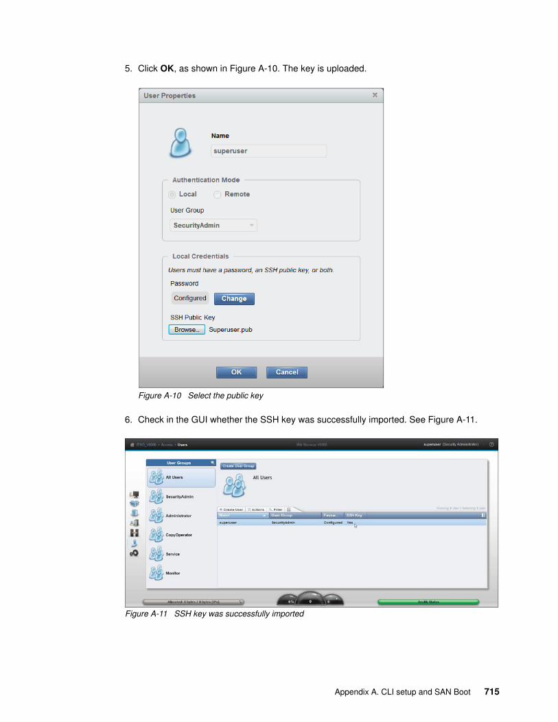
5. Click OK, as shown in Figure A-10. The key is uploaded.
Figure A-10 Select the public key
6. Check in the GUI whether the SSH key was successfully imported. See Figure A-11.
Figure A-11 SSH key was successfully imported
Appendix A. CLI setup and SAN Boot 715

Configuring the SSH client
Before you can use the CLI, you must configure the SSH client:
1. Start PuTTY. The PuTTY Configuration window opens (Figure A-12).
Figure A-12 PuTTY
In the right pane, select SSH as the connection type. Under the “Close window on exit” section, select Only on clean exit, which ensures that if any connection errors occur, they are displayed on the user’s window.
716 Implementing the Lenovo Storage V3700 V2 and V5030 Systems

2. In the Category pane, on the left side of the PuTTY Configuration window (Figure A-13), click Connection → SSH to open the PuTTY Configuration window Options controlling SSH connections view.
Figure A-13 SSH protocol version 2
Under Preferred SSH protocol version, select 2 only.
Appendix A. CLI setup and SAN Boot 717

3. In the Category pane on the left, click Connection → SSH → Auth, as shown in Figure A-14. More options are displayed for controlling SSH authentication.
In the Private key file for authentication field, either browse to or type the fully qualified directory path and file name of the SSH client private key file, which was created previously (for example, C:\Support Utils\PuTTY\icat.PPK).
Figure A-14 SSH authentication
718 Implementing the Lenovo Storage V3700 V2 and V5030 Systems

4. In the Category pane, click Session to return to the PuTTY Configuration window Basic options for your PuTTY session view (Figure A-15).
5. Enter the following information in these fields in the right pane:
– Host Name (or IP address): Specify the host name or system IP address of the Lenovo Storage V3700 V2, V3700 V2 XP, and V5030 clustered system.
– Saved Sessions: Enter a session name.
Figure A-15 Enter the session information
Appendix A. CLI setup and SAN Boot 719

6. Click Save to save the new session (Figure A-16).
Figure A-16 Save the new session
7. Figure A-17 shows the saved PUTTY session. Select the new session and click Open.
Figure A-17 Saved PUTTY session
720 Implementing the Lenovo Storage V3700 V2 and V5030 Systems

8. A PuTTY Security Alert window opens. Confirm it by clicking Yes (Figure A-18).
Figure A-18 Confirm the security alert
9. PuTTY now connects to the system and prompts you for a user name to log in as. Enter Superuser as the user name (Example A-1) and click Enter.
Example: A-1 Enter user name
login as: SuperuserAuthenticating with public key "putty public key"IBM_2077:ITSO V5000Gen2:Superuser>
The tasks to configure the CLI for the Lenovo Storage V3700 V2, V3700 V2 XP, and V5030 administration are complete.
SAN Boot
The Lenovo Storage V3700 V2, V3700 V2 XP, and V5030 support SAN Boot for Microsoft Windows, VMware, and many other operating systems. SAN Boot support can change, so regularly check the interoperability matrix at this address:
https://datacentersupport.lenovo.com/us/en/products/storage/lenovo-storage/v3700v2/6535/documentation
https://datacentersupport.lenovo.com/us/en/products/storage/lenovo-storage/v5030/6536/documentation
More information about SAN Boot is also available in the Multipath Subsystem Device Driver User’s Guide, which is available at the following address:
http://www.ibm.com/support/docview.wss?rs=503&context=HW26L&uid=ssg1S7000303
Appendix A. CLI setup and SAN Boot 721

Enabling SAN Boot for Windows
Complete the following procedure if you want to install a Windows host by using SAN Boot:
1. Configure the Lenovo Storage V3700 V2, V3700 V2 XP, and V5030 systems so that only the boot volume is mapped to the host.
2. Configure the Fibre Channel storage area network (SAN) so that the host sees only one Lenovo Storage V3700 V2, V3700 V2 XP, and V5030 systems node port. Multiple paths during installation are not supported.
3. Configure and enable the host bus adapter (HBA) BIOS.
4. Install the operating system by using the normal procedure, selecting the volume as the partition on which to install.
5. Install Subsystem Device Driver Device Specific Module (SDDDSM) after the installation completes.
6. Modify your SAN zoning to allow multiple paths.
7. Check your host to see whether all paths are available.
8. Set redundant boot devices in the HBA BIOS to enable the host to boot when its original path fails.
Enabling SAN Boot for VMware
Complete the following steps if you want to install a VMware ESX host by using SAN Boot:
1. Configure the Lenovo Storage V3700 V2, V3700 V2 XP, and V5030 systems so that only the boot volume is mapped to the host.
2. Configure the Fibre Channel SAN so that the host sees only one Lenovo Storage V3700 V2, V3700 V2 XP, and V5030 systems node port. Multiple paths during installation are not supported.
3. Configure and enable the HBA BIOS.
4. Install the operating system by using the normal procedure, selecting the volume as the partition on which to install.
5. Modify your SAN zoning to allow multiple paths.
6. Check your host to see whether all paths are available and modify the multipath policy, if required.
Windows SAN Boot migration
If your host runs a Windows Server 2000, Windows Server 2003, Windows Server 2008, or Windows 2012 operating system and uses existing SAN Boot images that are controlled by storage controllers, you can migrate these images to image-mode volumes that are controlled by the Lenovo Storage V3700 V2, V3700 V2 XP, and V5030 systems.
HBAs: You might need to load an additional HBA device driver during installation, depending on your Windows version and the HBA type.
HBAs: You might need to load an additional HBA device driver during installation, depending on your ESX level and the HBA type.
722 Implementing the Lenovo Storage V3700 V2 and V5030 Systems

Complete the following steps to migrate your existing SAN Boot images:
1. If the existing SAN Boot images are controlled by an Lenovo storage controller that uses the Subsystem Device Driver (SDD) as the multipathing driver, you must use SDD V1.6 or later. Run the SDD datapath set bootdiskmigrate 2077 command to prepare the host for image migration. For more information, see the Multipath Subsystem Device Driver documentation.
2. Shut down the host.
3. Complete the following configuration changes on the storage controller:
a. Write down the Small Computer System Interface (SCSI) logical unit number (LUN) ID that each volume is using, for example, boot LUN SCSI ID 0, Swap LUN SCSI ID 1, and Database LUN SCSID 2.
b. Remove all of the image-to-host mappings from the storage controller.
c. Map the existing SAN Boot image and any other disks to the Lenovo Storage V3700 V2, V3700 V2 XP, and V5030 systems.
4. Change the zoning so that the host can see the Lenovo Storage V3700 V2, V3700 V2 XP, and V5030 I/O group for the target image mode volume.
5. Complete the following configuration changes on the Lenovo Storage V3700 V2, V3700 V2 XP, and V5030 systems:
a. Create an image mode volume for the managed disk (MDisk) that contains the SAN Boot image. Use the MDisk unique identifier to specify the correct MDisk.
b. Create a host object and assign the host HBA ports.
c. Map the image mode volume to the host by using the same SCSI ID as before. For example, you might map the boot disk to the host with SCSI LUN ID 0.
d. Map the swap disk to the host, if required. For example, you might map the swap disk to the host with SCSI LUN ID 1.
6. Change the boot address of the host by completing the following steps:
a. Restart the host and open the HBA BIOS utility of the host during the booting process.
b. Set the BIOS settings on the host to find the boot image at the worldwide port name (WWPN) of the node that is zoned to the HBA port.
7. If SDD V1.6 or later is installed and you run bootdiskmigrate in step 1, reboot your host, update SDDDSM to the current level, and go to step 14 on page 724. If SDD V1.6 is not installed, go to step 8.
8. Modify the SAN zoning so that the host sees only one path to the Lenovo Storage V3700 V2, V3700 V2 XP, and V5030.
9. Boot the host in single-path mode.
10.Uninstall any multipathing driver that is not supported for the Lenovo Storage V3700 V2, V3700 V2 XP, and V5030systems hosts that run the applicable Windows Server operating system.
11. Install SDDDSM.
12.Restart the host in single-path mode. Ensure that SDDDSM was correctly installed.
SAN Boot procedures: For SAN Boot procedures for other operating systems, check the LenovoInformation Center for the Lenovo Storage V3700 V2, V3700 V2 XP, and V5030:
http://systemx.lenovofiles.com/help/topic/com.lenovo.storage.v3700.doc/lenovo_vseries.html
Appendix A. CLI setup and SAN Boot 723

13.Modify the SAN zoning to enable multipathing.
14.Rescan the drives on your host and check that all paths are available.
15.Reboot your host and enter the HBA BIOS.
16.Configure the HBA settings on the host. Ensure that all HBA ports are boot-enabled and that they can see both nodes in the I/O group that contains the SAN Boot image. Configure the HBA ports for redundant paths.
17.Exit the BIOS utility and finish starting the host.
Map any additional volumes to the host, as required.
724 Implementing the Lenovo Storage V3700 V2 and V5030 Systems

Notices
Lenovo may not offer the products, services, or features discussed in this document in all countries. Consult your local Lenovo representative for information on the products and services currently available in your area. Any reference to a Lenovo product, program, or service is not intended to state or imply that only that Lenovo product, program, or service may be used. Any functionally equivalent product, program, or service that does not infringe any Lenovo intellectual property right may be used instead. However, it is the user's responsibility to evaluate and verify the operation of any other product, program, or service.
Lenovo may have patents or pending patent applications covering subject matter described in this document. The furnishing of this document does not give you any license to these patents. You can send license inquiries, in writing, to:
Lenovo (United States), Inc.1009 Think Place - Building OneMorrisville, NC 27560U.S.A.Attention: Lenovo Director of Licensing
LENOVO PROVIDES THIS PUBLICATION “AS IS” WITHOUT WARRANTY OF ANY KIND, EITHER EXPRESS OR IMPLIED, INCLUDING, BUT NOT LIMITED TO, THE IMPLIED WARRANTIES OF NON-INFRINGEMENT, MERCHANTABILITY OR FITNESS FOR A PARTICULAR PURPOSE. Some jurisdictions do not allow disclaimer of express or implied warranties in certain transactions, therefore, this statement may not apply to you.
This information could include technical inaccuracies or typographical errors. Changes are periodically made to the information herein; these changes will be incorporated in new editions of the publication. Lenovo may make improvements and/or changes in the product(s) and/or the program(s) described in this publication at any time without notice.
The products described in this document are not intended for use in implantation or other life support applications where malfunction may result in injury or death to persons. The information contained in this document does not affect or change Lenovo product specifications or warranties. Nothing in this document shall operate as an express or implied license or indemnity under the intellectual property rights of Lenovo or third parties. All information contained in this document was obtained in specific environments and is presented as an illustration. The result obtained in other operating environments may vary.
Lenovo may use or distribute any of the information you supply in any way it believes appropriate without incurring any obligation to you.
Any references in this publication to non-Lenovo Web sites are provided for convenience only and do not in any manner serve as an endorsement of those Web sites. The materials at those Web sites are not part of the materials for this Lenovo product, and use of those Web sites is at your own risk.
Any performance data contained herein was determined in a controlled environment. Therefore, the result obtained in other operating environments may vary significantly. Some measurements may have been made on development-level systems and there is no guarantee that these measurements will be the same on generally available systems. Furthermore, some measurements may have been estimated through extrapolation. Actual results may vary. Users of this document should verify the applicable data for their specific environment.
Note: This document is based on an IBM Redbooks publication. The content was used with permission.
© Copyright Lenovo 2018. All rights reserved. 725

Trademarks
Lenovo, the Lenovo logo, and For Those Who Do are trademarks or registered trademarks of Lenovo in the United States, other countries, or both. These and other Lenovo trademarked terms are marked on their first occurrence in this information with the appropriate symbol (® or ™), indicating US registered or common law trademarks owned by Lenovo at the time this information was published. Such trademarks may also be registered or common law trademarks in other countries. A current list of Lenovo trademarks is available on the Web at https://www3.lenovo.com/us/en/legal/copytrade/.
The following terms are trademarks of Lenovo in the United States, other countries, or both:
Lenovo(logo)® Lenovo®
The following terms are trademarks of other companies:
Linux is a trademark of Linus Torvalds in the United States, other countries, or both.
Hyper-V, Internet Explorer, Microsoft, Microsoft Edge, SQL Server, Windows, Windows Server, and the Windows logo are trademarks of Microsoft Corporation in the United States, other countries, or both.
Other company, product, or service names may be trademarks or service marks of others.
726 Implementing the Lenovo Storage V3700 V2 and V5030 Systems


BUILDING TECHNICAL INFORMATION BASED ON PRACTICAL EXPERIENCE
At Lenovo Press, we
bring together experts
to produce technical
publications around
topics of importance to
you, providing
information and best
practices for using
Lenovo products and
solutions to solve IT
challenges.
lenovopress.com LP-0836-00
Implementing the Lenovo Storage V3700 V2 and V5030 Systems
Provides overview of Lenovo Storage V3700 V2, V3700 V2 XP and V5030 systems
Introduces configuration setup for the storage systems
Explains storage terminologies and concepts for various applications
Describes troubleshooting and monitoring procedures
Organizations of all sizes face the challenge of managing massive volumes of increasingly valuable data. But storing this data can be costly, and extracting value from the data is becoming more difficult. IT organizations have limited resources but must stay responsive to dynamic environments and act quickly to consolidate, simplify, and optimize their IT infrastructures. The Lenovo Storage V3700 V2, V2 XP and V5030 systems provide a smarter solution that is affordable, easy to use, and self-optimizing, which enables organizations to overcome these storage challenges.
These storage systems deliver efficient, entry-level configurations that are designed to meet the needs of small and midsize businesses. Designed to provide organizations with the ability to consolidate and share data at an affordable price, the Lenovo Storage V3700 V2, V2 XP and V5030 offer advanced software capabilities that are found in more expensive systems.
This book is intended for pre-sales and post-sales technical support professionals and storage administrators. It applies to the Lenovo Storage V3700 V2, V3700 V2 XP and V5030. The concepts in this book also relate to the IBM Storwize V3700 for Lenovo where applicable.
Back cover