Implementing Firewalls inside the Core Data Center Network · Implementing Firewalls inside the...
22
Implementation Guide Juniper Networks, Inc. 1194 North Mathilda Avenue Sunnyvale, California 94089 USA 408.745.2000 1.888 JUNIPER www.juniper.net Implementing Firewalls inside the Core Data Center Network Best Practices for Implementing Juniper Networks Firewall Devices in the Data Center Core Part Number: 801004-001 June 2008
Transcript of Implementing Firewalls inside the Core Data Center Network · Implementing Firewalls inside the...
Implementation Guide
Juniper Networks, Inc.1194 North Mathilda AvenueSunnyvale, California 94089 USA408.745.20001.888 JUNIPERwww.juniper.net
Implementing Firewalls inside the Core Data Center Network Best Practices for Implementing Juniper Networks Firewall Devices in the Data Center Core
Part Number: 801004-001 June 2008

Copyright ©2008, Juniper Networks, Inc.2
Implementing Firewalls inside the Core Data Center Network
Table of ContentsIntroduction . . . . . . . . . . . . . . . . . . . . . . . . . . . . . . . . . . . . . . . . . . . . . . . . . . . . . . . . . . . . . . . . . . . . 4
Scope . . . . . . . . . . . . . . . . . . . . . . . . . . . . . . . . . . . . . . . . . . . . . . . . . . . . . . . . . . . . . . . . . . . . . . . . . 4
Target Audience . . . . . . . . . . . . . . . . . . . . . . . . . . . . . . . . . . . . . . . . . . . . . . . . . . . . . . . . . . . . . . . . . 5
Requirements for Deploying the Firewall in the Data Center Core . . . . . . . . . . . . . . . . . . . . . . . . . . . 5
Data Center Reference Design . . . . . . . . . . . . . . . . . . . . . . . . . . . . . . . . . . . . . . . . . . . . . . . . . . 6
Design and Implementation Guidelines . . . . . . . . . . . . . . . . . . . . . . . . . . . . . . . . . . . . . . . . . . . . . . . 7
Deploying the Firewall in the Data Center Core . . . . . . . . . . . . . . . . . . . . . . . . . . . . . . . . . . . . . . 7
Firewall as Default Gateway . . . . . . . . . . . . . . . . . . . . . . . . . . . . . . . . . . . . . . . . . . . . . . . . . 9
Bypassing the Firewall (Using Private Routing Instance of MX-series Router) . . . . . . . . . . . 10
Directly Connecting to the Network Core (Connecting to the Core Routing Instance
of the MX-series Router) . . . . . . . . . . . . . . . . . . . . . . . . . . . . . . . . . . . . . . . . . . . . . . . . . . .11
Using a Dynamic Routing Protocol OSPF for Firewall Integration . . . . . . . . . . . . . . . . . . . . . . . 12
Virtual Systems—When to Use VSYS . . . . . . . . . . . . . . . . . . . . . . . . . . . . . . . . . . . . . . . . . . . . 12
Summary . . . . . . . . . . . . . . . . . . . . . . . . . . . . . . . . . . . . . . . . . . . . . . . . . . . . . . . . . . . . . . . . . . . . 13
Appendix A Code Samples . . . . . . . . . . . . . . . . . . . . . . . . . . . . . . . . . . . . . . . . . . . . . . . . . . . . . . . . 14
Firewall Config 1 . . . . . . . . . . . . . . . . . . . . . . . . . . . . . . . . . . . . . . . . . . . . . . . . . . . . . . . . . . . . 14
MX config 1 . . . . . . . . . . . . . . . . . . . . . . . . . . . . . . . . . . . . . . . . . . . . . . . . . . . . . . . . . . . . . . . 16
About Juniper Networks . . . . . . . . . . . . . . . . . . . . . . . . . . . . . . . . . . . . . . . . . . . . . . . . . . . . . . . . . . 22

Copyright ©2008, Juniper Networks, Inc. 3
Implementing Firewalls inside the Core Data Center Network
List of FiguresFigure 1 . MX-series Routers in the Core of the Data Center Network . . . . . . . . . . . . . . . . . . . . . . . . . 6
Figure 2 . Firewall Centrally Located—Logical Example . . . . . . . . . . . . . . . . . . . . . . . . . . . . . . . . . . . . 8
Figure 3 . VSYS on NetScreen Firewall Communications Example . . . . . . . . . . . . . . . . . . . . . . . . . . . . 9
Figure 4 . Logical Example of Firewall First . . . . . . . . . . . . . . . . . . . . . . . . . . . . . . . . . . . . . . . . . . . . 10
Figure 5 . Multiple Routing Instances Bypassing the Firewall . . . . . . . . . . . . . . . . . . . . . . . . . . . . . . . .11
Figure 6 . Example of Logical Core Connection . . . . . . . . . . . . . . . . . . . . . . . . . . . . . . . . . . . . . . . . . .11
Figure 7 . Example of Firewall/Router Connected to Core Router via OSPF . . . . . . . . . . . . . . . . . . . . 12
Copyright ©2008, Juniper Networks, Inc.4
Implementing Firewalls inside the Core Data Center Network
IntroductionData centers are the core of a business technology infrastructure . They control and store the most critical services and data of an organization . In the past several years, applications have scaled from single server deployments into multitier applications . As a result, this trend has caused the data center to become a large, sprawling network . Each tier of an application is grouped together with similar services into its own logical container on the network . Between these various containers, a network administrator should apply a layer of network security .
However, this needed network security layer can become a burden for network and security administrators to manage and control . Both groups have two different tasks that do not require collaboration .
The network administrator needs to ensure immediate and reliable delivery of the application data . The security administrator needs to ensure that only the proper devices communicate to each other over a limited set of protocols . In addition, the security administrator needs to deliver data that is free from attacks and malicious intent .
Juniper Networks offers a hybrid design that allows select networks to operate behind a stateful firewall but allow other networks to bypass the firewall, if needed . This approach provides for the best of both worlds in allowing only required applications to be placed behind a firewall .
There are several common realms that network and security administrators should consider when deploying a firewall inside the data center .
Performance – Network administrators want to ensure the fastest possible transaction rate •between servers . However, note that when a firewall is positioned between two servers, it can add some latency to the transaction .
Reliability – Because a new device now needs to be deployed between communicating •applications, the administrators should determine how to enforce reliability between two endpoints .
ScopeThis guide focuses on a modular design for placing a firewall inside the data center . This design consists of four major elements that offer flexible options for deploying the firewall . This guide also discusses other major design elements such as:
Dynamic Routing Integration•
High Availability (HA) •
Network Integration•
Discussions for deploying firewalls inside a data center concentrate on where to strategically deploy the firewalls, what are the best methods in doing so, and the most common problems associated with implementing firewalls in a data center .
NOTE: The designs presented in this guide extend beyond the use case for just a firewall . They also can be applied to any type of service that can reside in the core of the network . This includes other elements such as Intrusion Detection and Prevention (IDP) devices, WAN accelerators (Juniper Networks WX platforms) or application load balancers . To use this guide for another product, replace the deployment location of the firewall with the alternate product .
However, prior to implementing these designs, network administrators must know the types of services that the firewall provides, and how the firewall is used to separate various application tiers . They must also understand the challenges for deploying a firewall inside the data center and the considerations that should be regarded prior to deploying the firewalls, and how firewalls can possibly affect network performance .
Refer to Implementing HA at the Enterprise Data Center Edge to Connect to a Large Number of Branch Offices to learn more about edge network design and edge firewall deployment .
Copyright ©2008, Juniper Networks, Inc. 5
Implementing Firewalls inside the Core Data Center Network
Target AudienceSystems engineers who need to understand data center deployment strategies•
System integrators who need to deploy firewalls in data center networks•
Network architects who need to understand the implications of deploying firewalls in data centers•
Requirements for Deploying the Firewall in the Data Center CoreDeploying a firewall inside the data center is a challenging task . A firewall is typically seen as a limited network device that is deployed at a specific chokepoint/bottleneck in the network . Consequently, deploying at a particular chokepoint provides little flexibility and inhibits the design .
To determine the proper deployment strategy, first review firewall requirements . By thoroughly understanding the deployment challenges, the network administrator can clearly understand the required components for a successful design .
First, this document discusses the types of services that the firewall provides, and how it needs to separate various application tiers . Then there is a review of the challenges for deploying a firewall inside the data center and the considerations that should be understood prior to deploying the firewalls . Lastly, performance issues are discussed .
The following are the key requirements for deploying a firewall inside the data center:
The firewall should restrict traffic flow between two or more hosts in a stateful manner .•
Network-based services such as Network Address Translation (NAT), VPN or Intrusion •Prevention System (IPS) need to be provided .
Administrators must remember that legacy applications (applications that are not written to •adhere to firewall standards) break . This problem usually occurs from a legacy application that is unable to operate in a stateful manner because the application uses non-standard methods to communicate between hosts . If this happens, usually all of the firewall benefits are lost because the entire firewall is typically removed from the network .
Because the data center is often the most dense server environment in the network, it •requires the highest speeds and lowest latencies available . This is regardless of whether adding devices create further demands (adding more devices create a reduction in speed and increased latency) .
Copyright ©2008, Juniper Networks, Inc.6
Implementing Firewalls inside the Core Data Center Network
Data Center Reference DesignFor more details regarding Juniper Networks data center network reference architecture, refer to the Enterprise Data Center Network Reference Architecture.
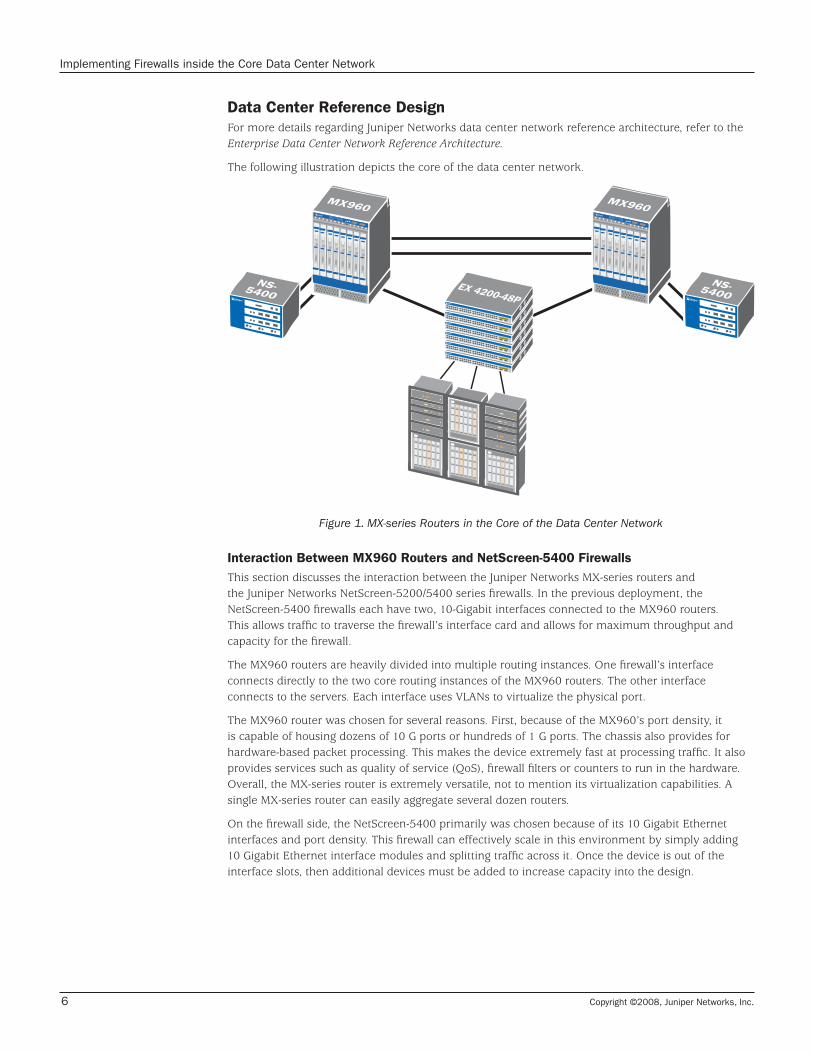
The following illustration depicts the core of the data center network .
069XM069XM
EX 4200-48P
EX 4200-48P
EX 4200-48P
EX 4200-48P
EX 4200-48P
EX 4200-48P
NS-5400NS-5400
Figure 1. MX-series Routers in the Core of the Data Center Network
Interaction Between MX960 Routers and NetScreen-5400 FirewallsThis section discusses the interaction between the Juniper Networks MX-series routers and the Juniper Networks NetScreen-5200/5400 series firewalls . In the previous deployment, the NetScreen-5400 firewalls each have two, 10-Gigabit interfaces connected to the MX960 routers . This allows traffic to traverse the firewall’s interface card and allows for maximum throughput and capacity for the firewall .
The MX960 routers are heavily divided into multiple routing instances . One firewall’s interface connects directly to the two core routing instances of the MX960 routers . The other interface connects to the servers . Each interface uses VLANs to virtualize the physical port .
The MX960 router was chosen for several reasons . First, because of the MX960’s port density, it is capable of housing dozens of 10 G ports or hundreds of 1 G ports . The chassis also provides for hardware-based packet processing . This makes the device extremely fast at processing traffic . It also provides services such as quality of service (QoS), firewall filters or counters to run in the hardware . Overall, the MX-series router is extremely versatile, not to mention its virtualization capabilities . A single MX-series router can easily aggregate several dozen routers .
On the firewall side, the NetScreen-5400 primarily was chosen because of its 10 Gigabit Ethernet interfaces and port density . This firewall can effectively scale in this environment by simply adding 10 Gigabit Ethernet interface modules and splitting traffic across it . Once the device is out of the interface slots, then additional devices must be added to increase capacity into the design .
Copyright ©2008, Juniper Networks, Inc. 7
Implementing Firewalls inside the Core Data Center Network
Design and Implementation Guidelines Hardware Requirements:
NS-5200/NS-5400•
M2/M3 Management Card•
SPM2/SPM3 2XGE•
ISG 2000/ISG 1000•
MX960 Router•
DPCE-4X-10GE-R•
Software Requirements:
ScreenOS 6 .0r2 – Firewalls•
JUNOS 9 .0R2 .10 – MX•
As with any network design, there is no single design that is appropriate for all organizations . However, this guide highlights a hybrid approach whereby you can implement a combination (mix and match) of all three deployment strategies that are listed next .
Deploying the Firewall in the Data Center CoreThis section focuses on how to deploy the firewall in the data center core . Ultimately, the firewall must be in the path of the traffic that it is attempting to filter . There are several different techniques that security administrators and network administrators may need to use to optimally accomplish this task:
Configure the firewall(s) as default gateway •
Bypass the firewall(s) if required•
Connect directly to the network core (without any firewall service)•
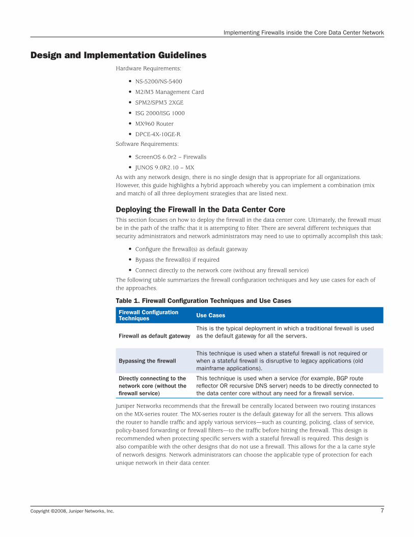
The following table summarizes the firewall configuration techniques and key use cases for each of the approaches .
Table 1. Firewall Configuration Techniques and Use Cases
Firewall Configuration Techniques Use Cases
Firewall as default gatewayThis is the typical deployment in which a traditional firewall is used as the default gateway for all the servers.
Bypassing the firewallThis technique is used when a stateful firewall is not required or when a stateful firewall is disruptive to legacy applications (old mainframe applications).
Directly connecting to the network core (without the firewall service)
This technique is used when a service (for example, BGP route reflector OR recursive DNS server) needs to be directly connected to the data center core without any need for a firewall service.
Juniper Networks recommends that the firewall be centrally located between two routing instances on the MX-series router . The MX-series router is the default gateway for all the servers . This allows the router to handle traffic and apply various services—such as counting, policing, class of service, policy-based forwarding or firewall filters—to the traffic before hitting the firewall . This design is recommended when protecting specific servers with a stateful firewall is required . This design is also compatible with the other designs that do not use a firewall . This allows for the a la carte style of network designs . Network administrators can choose the applicable type of protection for each unique network in their data center .
Copyright ©2008, Juniper Networks, Inc.8
Implementing Firewalls inside the Core Data Center Network
The firewall uses a VLAN sub-interface and logically connects to one of the MX-series router’s logical interfaces . This connection emulates a point-to-point link between the firewall and the router . See the following example section and for further details, see the Concepts & Examples ScreenOS Reference Guide: Vol 2, Fundamentals from the ScreenOS documentation .
Example – Create a new VLAN Sub-interface in ScreenOS:set interface <INT_NAME> tag <VLANID> zone <ZONENAME>
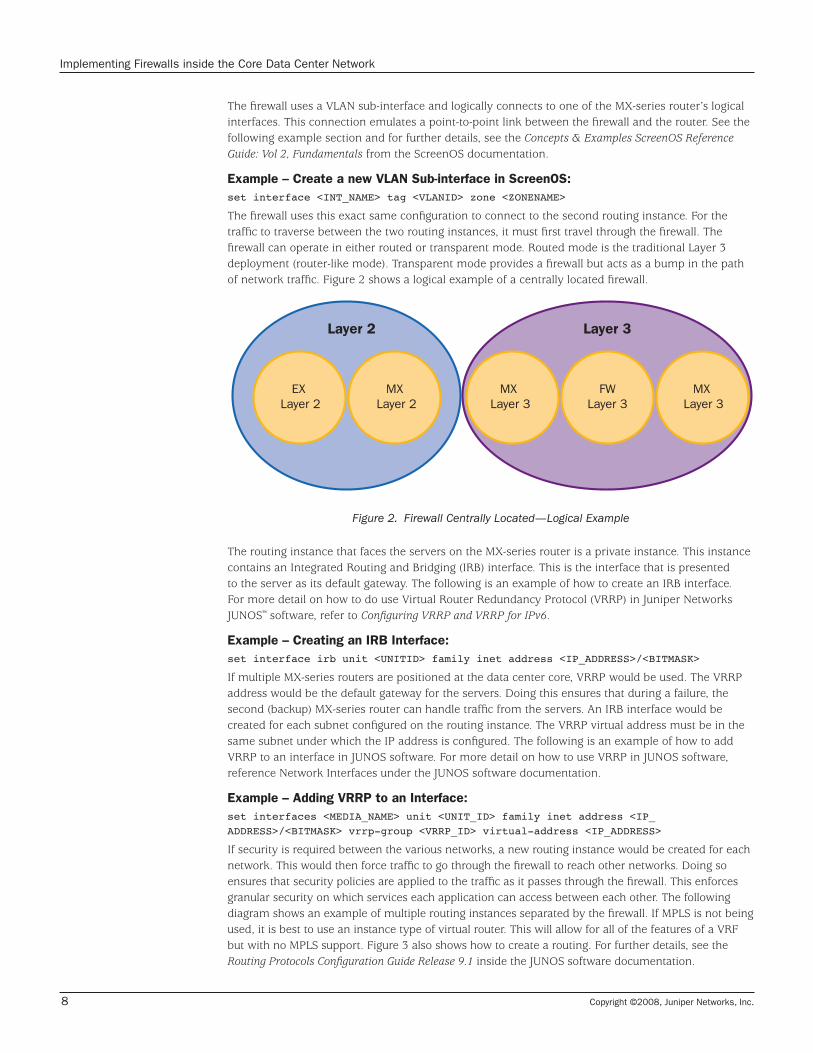
The firewall uses this exact same configuration to connect to the second routing instance . For the traffic to traverse between the two routing instances, it must first travel through the firewall . The firewall can operate in either routed or transparent mode . Routed mode is the traditional Layer 3 deployment (router-like mode) . Transparent mode provides a firewall but acts as a bump in the path of network traffic . Figure 2 shows a logical example of a centrally located firewall .
Layer 2 Layer 3
EX Layer 2
MX Layer 2
MX Layer 3
FWLayer 3
MX Layer 3
Figure 2. Firewall Centrally Located—Logical Example
The routing instance that faces the servers on the MX-series router is a private instance . This instance contains an Integrated Routing and Bridging (IRB) interface . This is the interface that is presented to the server as its default gateway . The following is an example of how to create an IRB interface . For more detail on how to do use Virtual Router Redundancy Protocol (VRRP) in Juniper Networks JUNOS™ software, refer to Configuring VRRP and VRRP for IPv6 .
Example – Creating an IRB Interface:set interface irb unit <UNITID> family inet address <IP_ADDRESS>/<BITMASK>
If multiple MX-series routers are positioned at the data center core, VRRP would be used . The VRRP address would be the default gateway for the servers . Doing this ensures that during a failure, the second (backup) MX-series router can handle traffic from the servers . An IRB interface would be created for each subnet configured on the routing instance . The VRRP virtual address must be in the same subnet under which the IP address is configured . The following is an example of how to add VRRP to an interface in JUNOS software . For more detail on how to use VRRP in JUNOS software, reference Network Interfaces under the JUNOS software documentation .
Example – Adding VRRP to an Interface:set interfaces <MEDIA_NAME> unit <UNIT_ID> family inet address <IP_ADDRESS>/<BITMASK> vrrp-group <VRRP_ID> virtual-address <IP_ADDRESS>
If security is required between the various networks, a new routing instance would be created for each network . This would then force traffic to go through the firewall to reach other networks . Doing so ensures that security policies are applied to the traffic as it passes through the firewall . This enforces granular security on which services each application can access between each other . The following diagram shows an example of multiple routing instances separated by the firewall . If MPLS is not being used, it is best to use an instance type of virtual router . This will allow for all of the features of a VRF but with no MPLS support . Figure 3 also shows how to create a routing . For further details, see the Routing Protocols Configuration Guide Release 9.1 inside the JUNOS software documentation .

Copyright ©2008, Juniper Networks, Inc. 9
Implementing Firewalls inside the Core Data Center Network
Example – Creating a New Routing Instance:set routing-instances <INSTANCE_NAME> instance-type virtual-router
The configuration on the firewall uses virtual systems or VSYS, as shown in Figure 3 . While VSYS is discussed in depth in the next section, this section covers the configuration elements of the firewall . The firewall has a VSYS for a group of similar networks . This configuration is designed to face the VSYS toward the server networks . The root system on the firewall is positioned toward the core virtual routers . The core virtual routers are shared and can be used by multiple virtual systems . This arrangement provides a common location for all of the virtual systems with a centrally located
firewall, thereby allowing access between each VSYS .
Figure 3. VSYS on NetScreen Firewall Communications Example
For details on learning how to configure the firewall, see Appendix A – Firewall config 1 . For details on learning how to configure the MX-series router, see Appendix A –MX config 1 .
The next section explores each of the firewall deployment techniques in greater detail .
Firewall as Default GatewayIn this deployment, the firewall acts as the default gateway for the servers, thus allowing the firewall to directly receive all traffic . Doing this would take the MX-series router out of the direct path of the servers . This would be the more traditional deployment style for a firewall inside the data center . The design would be used typically in the event that a less complex environment would be required . Although the previous example is slightly more complex, it is still more flexible and provides more services than this design .
In this design, it is assumed that the firewall is presenting an interface with an IP address to the servers . The second interface would use a VLAN sub-interface and logically connect into one of the MX-series router’s logical interfaces . The MX-series router’s interface would be inside of a routing instance in the router . The firewall presents a virtual security interface to the servers and acts as their next hop default gateway . For details concerning HA, see the ScreenOS software documentation, Concepts & Examples ScreenOS Reference Guide: Vol 11, High Availability .
RootSystem
Server Server
UntrustVR
Shared Untrust Interface
VSYS VSYS
VR VR
One Session
Step 1: Flow Lookup 1
Step 2: Flow Lookup 2

Copyright ©2008, Juniper Networks, Inc.10
Implementing Firewalls inside the Core Data Center Network
However, for traffic to get between the two routing instances, it must still go through the firewall . This is accomplished in a pure Layer 3 mode on the firewall . Figure 4 shows an example of a logical firewall first configuration . This design is similar to the previous one . The primary difference is that the private routing instance on the MX-series router is removed . The “Core” routing instance on the MX-series router (Appendix A – MX config 1) is still used . The firewall uses NSRP to provide a reliable interface for servers to use as a default gateway . See Appendix A – Firewall config 1 for firewall configuration code .
Layer 2
EX Layer 2
MX Layer 2
Layer 3
FirewallLayer 3
MXLayer 3
Core
Figure 4. Logical Example of Firewall First
Bypassing the Firewall (Using Private Routing Instance of MX-series Router)There may be times when a firewall is either not required or is unable to properly secure an application . Perhaps the application uses a protocol that does not maintain any sort of state or it is not beneficial to maintain state for the application, such as for HTTP-only traffic . In this case, you can bypass the firewall . Presenting a Layer 3 interface to the servers from the MX-series router provides the default gateway for the servers .
The routing instance that faces the servers on the MX-series router is a private instance . This instance contains an IRB . This is the interface that is presented to the server as its default gateway . When multiple MX-series routers are located at the data center core, VRRP should be used . The VRRP address would be the default gateway for the servers . Using VRRP ensures that during a failure, the second (backup) MX-series router would handle traffic from the servers . An IRB interface would be created for each subnet configured on the routing instance .
If security is required between the various networks, a new routing instance should be created for each network . Creating a new routing instance forces traffic to flow through the firewall and traverse between the various networks . Doing so enforces security policies to be applied to the traffic as it traverses through the firewall . This enforces granular security on which services each application can access between each other .

Copyright ©2008, Juniper Networks, Inc. 11
Implementing Firewalls inside the Core Data Center Network
Layer 2
EX Layer 2
MX Layer 2
Layer 3
MXLayer 3
MXLayer 3
Core
Figure 5. Multiple Routing Instances Bypassing the Firewall
Figure 5 shows an example of multiple routing instances bypassing the firewall . To share routing information between the two routing instances, the administrator would need to create route export policies . This would be accomplished between the private instance and the core MX instance . See Appendix A – MX config 1 which shows the configuration for this design .
Directly Connecting to the Network Core (Connecting to the Core Routing Instance of the MX-series Router)This model is similar to the technique of bypassing the firewall . The only difference is that the server network is directly connected to the core or central routing instance . This is typically not done for servers but for specific network devices . Examples of this are connecting a route reflector directly into the core or connecting the firewall itself directly into the core . Devices connecting into the core are typically connected with a direct physical link to the MX-series router and are configured with a point-to-point network link . Figure 6 shows an example of core connection . While this would not be a deployment strategy for a server, it is included here for completeness .
Layer 2
EX Layer 2
MX Layer 2
Layer 3
MXLayer 3
Figure 6. Example of Logical Core Connection
Copyright ©2008, Juniper Networks, Inc.12
Implementing Firewalls inside the Core Data Center Network
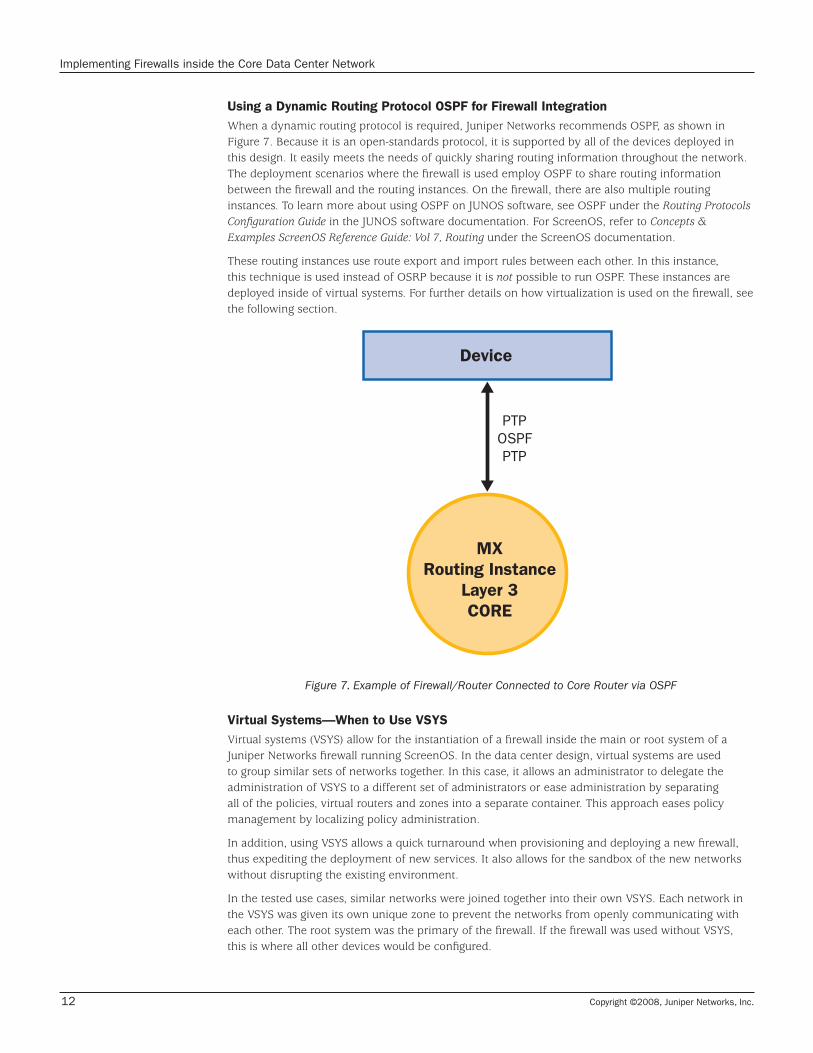
Using a Dynamic Routing Protocol OSPF for Firewall Integration When a dynamic routing protocol is required, Juniper Networks recommends OSPF, as shown in Figure 7 . Because it is an open-standards protocol, it is supported by all of the devices deployed in this design . It easily meets the needs of quickly sharing routing information throughout the network . The deployment scenarios where the firewall is used employ OSPF to share routing information between the firewall and the routing instances . On the firewall, there are also multiple routing instances . To learn more about using OSPF on JUNOS software, see OSPF under the Routing Protocols Configuration Guide in the JUNOS software documentation . For ScreenOS, refer to Concepts & Examples ScreenOS Reference Guide: Vol 7, Routing under the ScreenOS documentation .
These routing instances use route export and import rules between each other . In this instance, this technique is used instead of OSRP because it is not possible to run OSPF . These instances are deployed inside of virtual systems . For further details on how virtualization is used on the firewall, see the following section .
MXRouting Instance
Layer 3CORE
Device
PTPOSPFPTP
Figure 7. Example of Firewall/Router Connected to Core Router via OSPF
Virtual Systems—When to Use VSYSVirtual systems (VSYS) allow for the instantiation of a firewall inside the main or root system of a Juniper Networks firewall running ScreenOS . In the data center design, virtual systems are used to group similar sets of networks together . In this case, it allows an administrator to delegate the administration of VSYS to a different set of administrators or ease administration by separating all of the policies, virtual routers and zones into a separate container . This approach eases policy management by localizing policy administration .
In addition, using VSYS allows a quick turnaround when provisioning and deploying a new firewall, thus expediting the deployment of new services . It also allows for the sandbox of the new networks without disrupting the existing environment .
In the tested use cases, similar networks were joined together into their own VSYS . Each network in the VSYS was given its own unique zone to prevent the networks from openly communicating with each other . The root system was the primary of the firewall . If the firewall was used without VSYS, this is where all other devices would be configured .

Copyright ©2008, Juniper Networks, Inc. 13
Implementing Firewalls inside the Core Data Center Network
This root system has specific properties allowing it to share its virtual routers and zones with the virtual systems . It also allows the various virtual systems to communicate with each other . The root system acts as a middle system between the virtual systems . Policy is applied separately on each of the virtual systems . The “Untrust” zone that resides in the root system is shared with all of the virtual systems (see Figure 3) . Traffic from one source zone that exists inside of each VSYS contains traffic that originates from one if its zones . Its destination zone must be the shared “Untrust” zone . For more details on using VSYS, refer to Concepts & Examples ScreenOS Reference Guide: Vol 10, Virtual Systems from the ScreenOS documentation .
In these designs, VSYS is used as a container to place similar networks into a separate policy domain . This method allows the policies to be grouped together and separate from any other system . After the firewalls are implemented and thousands of policies are deployed, the management benefits of the design will be apparent . By creating a modular design, it is also quick and painless to freely add and remove firewalls whenever needed .
Administrative DivisionOne feature of virtual systems is to create an administrative division of a firewall . It creates an instantiated firewall that can be operated by a separate set of administrators . All the typical administration tasks of managing a firewall can now be delegated to a separate department or team . This allows for a scalable management structure for complex designs . It also allows for the creation of a new firewall at little additional cost . If a department requires the use of a new firewall, the central administrators can create a new one and allow the department to use it .
Policy DivisionVirtual systems can be useful for dividing up policy sets . In a core data center a firewall may contain tens of thousands of policies . Managing this as a single rule set can be difficult . In a VSYS all of the policies that are specific to the VSYS are grouped together . So when a policy set needs to be updated, it is possible to make it easier to modify and manage the policies of the core network firewall .
Summary This implementation guide discusses Juniper Networks recommendations for deploying a firewall in the core of the data center . This modular design offers flexible options such as using the firewall as a default gateway, bypassing the firewall and directly connecting to the core of the network . These designs provide the benefit of creating a highly flexible architecture that deploys firewalls that can consolidate multiple physical firewalls while meeting the security requirements of the enterprise .
Copyright ©2008, Juniper Networks, Inc.14
Implementing Firewalls inside the Core Data Center Network
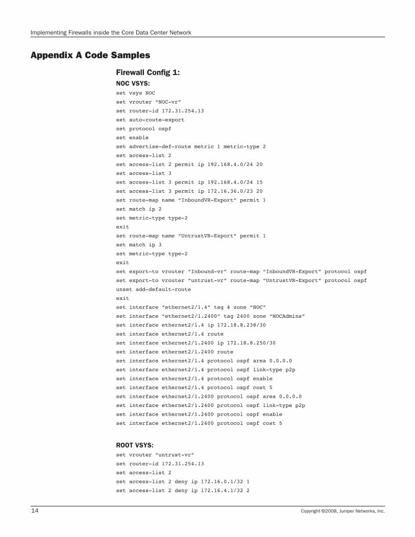
Appendix A Code Samples
Firewall Config 1:NOC VSYS:set vsys NOC
set vrouter “NOC-vr”
set router-id 172.31.254.13
set auto-route-export
set protocol ospf
set enable
set advertise-def-route metric 1 metric-type 2
set access-list 2
set access-list 2 permit ip 192.168.4.0/24 20
set access-list 3
set access-list 3 permit ip 192.168.4.0/24 15
set access-list 3 permit ip 172.16.36.0/23 20
set route-map name “InboundVR-Export” permit 1
set match ip 2
set metric-type type-2
exit
set route-map name “UntrustVR-Export” permit 1
set match ip 3
set metric-type type-2
exit
set export-to vrouter “Inbound-vr” route-map “InboundVR-Export” protocol ospf
set export-to vrouter “untrust-vr” route-map “UntrustVR-Export” protocol ospf
unset add-default-route
exit
set interface “ethernet2/1.4” tag 4 zone “NOC”
set interface “ethernet2/1.2400” tag 2400 zone “NOCAdmins”
set interface ethernet2/1.4 ip 172.18.8.238/30
set interface ethernet2/1.4 route
set interface ethernet2/1.2400 ip 172.18.8.250/30
set interface ethernet2/1.2400 route
set interface ethernet2/1.4 protocol ospf area 0.0.0.0
set interface ethernet2/1.4 protocol ospf link-type p2p
set interface ethernet2/1.4 protocol ospf enable
set interface ethernet2/1.4 protocol ospf cost 5
set interface ethernet2/1.2400 protocol ospf area 0.0.0.0
set interface ethernet2/1.2400 protocol ospf link-type p2p
set interface ethernet2/1.2400 protocol ospf enable
set interface ethernet2/1.2400 protocol ospf cost 5
ROOT VSYS:set vrouter “untrust-vr”
set router-id 172.31.254.13
set access-list 2
set access-list 2 deny ip 172.16.0.1/32 1
set access-list 2 deny ip 172.16.4.1/32 2
Copyright ©2008, Juniper Networks, Inc. 15
Implementing Firewalls inside the Core Data Center Network
set access-list 2 deny ip 172.16.8.1/32 3
set access-list 2 deny ip 172.16.12.1/32 4
set access-list 2 deny ip 172.16.16.1/32 5
set access-list 2 deny ip 172.16.20.1/32 6
set access-list 2 deny ip 172.16.24.1/32 7
set access-list 2 deny ip 172.16.28.1/32 8
set access-list 2 deny ip 172.16.32.1/32 9
set access-list 2 deny ip 172.16.36.1/32 10
set access-list 2 deny ip 192.168.4.1/32 11
set access-list 2 deny ip 172.16.128.1/32 12
set access-list 2 deny ip 172.16.40.1/32 13
set access-list 2 permit ip 172.16.0.0/16 20
set access-list 2 permit ip 192.168.4.0/24 25
set access-list 10
set access-list 10 deny ip 10.0.0.0/9 2
set access-list 10 permit ip 10.0.0.0/8 5
set route-map name “VSYS-Export” permit 1
set match ip 2
set metric-type type-2
exit
set route-map name “ImportToVSYS” permit 1
set match ip 10
exit
set export-to vrouter “ExternalNetwork-vr” route-map “ImportToVSYS” protocol ospf
set export-to vrouter “ExternalNetwork-vr” route-map “VSYS-Export” protocol imported
set export-to vrouter “NOC-vr” route-map “ImportToVSYS” protocol ospf
set export-to vrouter “InternalNetwork-vr” route-map “ImportToVSYS” protocol ospf
set protocol ospf
set redistribute route-map “VSYS-Export” protocol imported
exit
exit
set vrouter name “Inbound-vr” id 1025 sharable
set vrouter “Inbound-vr”
set router-id 172.31.254.13
set access-list 1
set access-list 1 permit default-route 1
set access-list 2
set access-list 2 permit ip 172.16.0.0/16 20
set access-list 2 permit ip 192.168.4.0/24 25
set route-map name “ExternalExport” permit 1
set match ip 2
set metric-type type-2
exit
set route-map name “ExportDefault” permit 1
set match ip 1
exit
set export-to vrouter “ExternalNetwork-vr” route-map “ExportDefault” protocol ospf
set export-to vrouter “NOC-vr” route-map “ExportDefault” protocol ospf
set protocol ospf

Copyright ©2008, Juniper Networks, Inc.16
Implementing Firewalls inside the Core Data Center Network
set redistribute route-map “ExternalExport” protocol imported
exit
exit
unset auto-route-export
set protocol ospf
set enable
exit
exit
set interface ethernet2/2.15 ip 172.18.8.190/30
set interface ethernet2/2.15 route
set interface ethernet2/2.20 ip 172.18.8.106/30
set interface ethernet2/2.20 route
set interface loopback.1 ip 172.31.254.13/32
set interface loopback.1 route
set interface loopback.1:1 ip 172.31.254.20/32
set interface loopback.1:1 route
set interface ethernet2/2.15 protocol ospf area 0.0.0.0
set interface ethernet2/2.15 protocol ospf link-type p2p
set interface ethernet2/2.15 protocol ospf enable
set interface loopback.1 protocol ospf area 0.0.0.0
set interface loopback.1 protocol ospf passive
set interface loopback.1 protocol ospf enable
set interface loopback.1:1 protocol ospf area 0.0.0.0
set interface loopback.1:1 protocol ospf passive
set interface loopback.1:1 protocol ospf enable
set interface ethernet2/2.20 protocol ospf area 0.0.0.0
set interface ethernet2/2.20 protocol ospf link-type p2p
set interface ethernet2/2.20 protocol ospf enable
set interface ethernet2/2.20 protocol ospf cost 5
MX config 1:Interfaces {
xe-1/1/0 {
description “Phy Connect to NS5400-A eth2/1”;
flexible-vlan-tagging;
encapsulation flexible-ethernet-services;
unit 4 {
vlan-id 4;
family inet {
address 172.18.8.237/30;
}
}
unit 2100 {
vlan-id 2100;
family inet {
address 172.18.8.205/30;
}
}
unit 2101 {

Copyright ©2008, Juniper Networks, Inc. 17
Implementing Firewalls inside the Core Data Center Network
vlan-id 2101;
family inet {
address 172.18.8.209/30;
}
}
unit 2102 {
vlan-id 2102;
family inet {
address 172.18.8.197/30;
}
}
unit 2103 {
vlan-id 2103;
family inet {
address 172.18.8.213/30;
}
}
unit 2104 {
vlan-id 2104;
family inet {
address 172.18.8.201/30;
}
}
unit 2105 {
vlan-id 2105;
family inet {
address 172.18.8.217/30;
}
}
unit 2106 {
vlan-id 2106;
family inet {
address 172.18.8.221/30;
}
}
unit 2107 {
vlan-id 2107;
family inet {
address 172.18.8.225/30;
}
}
unit 2108 {
vlan-id 2108;
family inet {
address 172.18.8.229/30;
}
}
unit 2109 {
vlan-id 2109;
family inet {

Copyright ©2008, Juniper Networks, Inc.18
Implementing Firewalls inside the Core Data Center Network
address 172.18.8.233/30;
}
}
unit 2111 {
vlan-id 2111;
family inet {
address 172.18.8.253/30;
}
}
unit 2112 {
vlan-id 2112;
family inet {
address 172.18.9.1/30;
}
}
unit 2400 {
vlan-id 2400;
family inet {
address 172.18.8.249/30;
}
}
}
xe-1/2/0 {
description “Phy Connect to NS5400-A eth2/2”;
flexible-vlan-tagging;
unit 15 {
description “Inbound Connect to NS5400-A eth2/2.15”;
vlan-id 15;
family inet {
address 172.18.8.189/30;
}
}
unit 20 {
description “Core Connect to NS5400-A eth2/2.20”;
vlan-id 20;
family inet {
address 172.18.8.105/30;
}
}
}
irb {
unit 4 {
family inet {
address 192.168.4.2/24 {
vrrp-group 0 {
virtual-address 192.168.4.1;
priority 200;
accept-data;
}
}
Copyright ©2008, Juniper Networks, Inc. 19
Implementing Firewalls inside the Core Data Center Network
}
}
unit 2400 {
family inet {
address 172.16.36.2/23 {
vrrp-group 0 {
virtual-address 172.16.36.1;
priority 200;
accept-data;
}
}
}
}
}
}
Routing-instances {
Core {
description “Routing Instance that is the Core Network”;
instance-type virtual-router;
interface ge-11/0/0.0;
interface ge-11/0/2.0;
interface ge-11/2/2.0;
interface ge-11/2/1.0;
interface ae0.0;
interface lo0.0;
interface ge-11/0/3.0;
interface ge-0/3/5.512;
interface xe-1/2/0.15;
routing-options {
aggregate {
route 10.0.0.0/8 policy branchAggregate;
}
router-id 172.31.254.11;
instance-import AppTestNetToCoreImport;
}
protocols {
bgp {
local-as 65100;
group RouteReflectors {
local-address 172.31.254.11;
neighbor 172.31.255.15 {
description “J6350-B RR2”;
peer-as 65100;
}
neighbor 172.31.254.15 {
description “J6350-A RR1”;
peer-as 65100;
}
}
}
Copyright ©2008, Juniper Networks, Inc.20
Implementing Firewalls inside the Core Data Center Network
ospf {
export branchAggregateToOSPF;
area 0.0.0.0 {
interface ge-11/0/0.0 {
interface-type p2p;
metric 5;
}
interface ge-11/0/2.0 {
interface-type p2p;
metric 500;
}
interface ge-11/2/2.0 {
interface-type p2p;
metric 5;
}
interface ge-11/2/1.0 {
interface-type p2p;
metric 500;
}
interface ae0.0 {
interface-type p2p;
}
interface lo0.0 {
passive;
}
interface ge-11/0/3.0 {
interface-type p2p;
}
interface ge-0/3/5.512 {
metric 1000;
}
interface xe-1/2/0.15 {
interface-type p2p;
metric 5;
}
}
}
}
}
InboundInternet {
instance-type virtual-router;
interface xe-1/2/0.20;
interface ge-11/2/0.0;
interface ge-11/0/1.0;
interface ae0.20;
routing-options {
router-id 172.31.254.11;
}
protocols {
ospf {
Copyright ©2008, Juniper Networks, Inc. 21
Implementing Firewalls inside the Core Data Center Network
area 0.0.0.0 {
interface ge-11/0/1.0 {
interface-type p2p;
metric 500;
}
interface ge-11/2/0.0 {
interface-type p2p;
metric 5;
}
interface xe-1/2/0.20 {
interface-type p2p;
metric 5;
}
interface ae0.20 {
interface-type p2p;
}
}
}
}
}
NOC {
instance-type virtual-router;
interface irb.4;
interface xe-1/1/0.4;
protocols {
ospf {
area 0.0.0.0 {
interface xe-1/1/0.4 {
interface-type p2p;
metric 5;
}
interface irb.4 {
passive;
}
}
22
Copyright 2008 Juniper Networks, Inc. All rights reserved. Juniper Networks, the Juniper Networks logo, NetScreen, and ScreenOS are registered trademarks of Juniper Networks, Inc. in the United States and other countries. JUNOS and JUNOSe are trademarks of Juniper Networks, Inc. All other trademarks, service marks, registered trademarks, or registered service marks are the property of their respective owners. Juniper Networks assumes no responsibility for any inaccuracies in this document. Juniper Networks reserves the right to change, modify, transfer, or otherwise revise this publication without notice.
CORPORATE HEADQUARTERS AND SALES HEADQUARTERS FOR NORTH AND SOUTH AMERICAJuniper Networks, Inc. 1194 North Mathilda Avenue Sunnyvale, CA 94089 USA Phone: 888.JUNIPER (888.586.4737) or 408.745.2000 Fax: 408.745.2100www.juniper.net
EAST COAST OFFICEJuniper Networks, Inc. 10 Technology Park Drive Westford, MA 01886-3146 USA Phone: 978.589.5800 Fax: 978.589.0800
ASIA PACIFIC REGIONAL SALES HEADQUARTERSJuniper Networks (Hong Kong) Ltd. 26/F, Cityplaza One1111 King’s RoadTaikoo Shing, Hong KongPhone: 852.2332.3636 Fax: 852.2574.7803
EUROPE, MIDDLE EAST, AFRICA REGIONAL SALES HEADQUARTERSJuniper Networks (UK) Limited Building 1 Aviator Park Station Road Addlestone Surrey, KT15 2PG, U.K. Phone: 44.(0).1372.385500 Fax: 44.(0).1372.385501
To purchase Juniper Networks solutions, please contact your Juniper Networks sales representative
at 1-866-298-6428 or authorized reseller.
Implementing Firewalls inside the Core Data Center Network
About Juniper NetworksJuniper Networks, Inc . is the leader in high-performance networking . Juniper offers a high-performance network infrastructure that creates a responsive and trusted environment for accelerating the deployment of services and applications over a single network . This fuels high-performance businesses . Additional information can be found at www .juniper .net .