Implementation of EOG-based Gaze Estimation in HMD … · Implementation of EOG-based Gaze...
8
Implementation of EOG-based Gaze Estimation in HMD with Head-tracker Hiromu Miyashita, Masaki Hayashi, Ken-ichi Okada Keio University 3-14-1 Hiyoshi, Kohoku-ku, Yokohama, Kanagawa 223-8522, Japan miyashita,hayamasa,[email protected] Abstract Head-mounted displays (HMDs) are effective devices for creating immersive virtual environments. Intuitive move- ment field-of view (FOV) is possible in virtual reality (VR) space with a HMD equipped with a head-tracker. However, gaze targets are not accurately detectable by the measure- ment of head movements alone. An eye-tracker is needed to determine gaze positions; however, such trackers currently negatively influence the experience of immersion in VR. In this study, EOG-based gaze estimation was imple- mented by mounting EOG equipment on a HMD equipped with a head-tracker. This method of gaze estimation ensured that the HMD screen was not hindered and head movements were possible. Disk electrodes attached to swimming gog- gles and a gyro-sensor were attached to the HMD in order to evaluate performance of this system. Additionally, digital filters were used as denoising algorithms. Accuracy of gaze estimation was experimentally deter- mined to be 68.9% for a HMD screen which was partitioned into eight target areas. Head-tracking with the gyro-sensor showed 99.4% accuracy. Time until input by the detection of eye movements was 0.37 seconds. These findings suggest that rough gaze positions are detectable by combining gaze estimation and head-tracking. 1. Introduction Head-mounted displays (HMD) are devices widely used to immerse users in virtual reality (VR). HMDs may also be used with head-tracking sensors, which enables the user to move the head to look around in the virtual world. For example, a 3-axis gyro sensor on the HMD measures head angle and correspondingly moves the field-of-view (FOV) in the same direction in real time. This intuitive interac- tion contributes to improve the quality of VR [1]. How- ever, HMDs having only a head-tracker cannot accurately and rapidly determine the user’s area of gaze since FOV movements consist of not only head movements but also eye movements. Large FOV movements often cause head movements and eye movements, where the eyes are directed to the gaze target before the head moves. However, short FOV movements require only the eyes, and not the head, to move, and the eyes can gaze in a direction different from the direction of the head. Therefore, accurate measurement of the user s area of gaze requires the use of eye-tracking sensors. Figure 1 shows an example of the difference be- tween head direction and actual gaze direction when the FOV moves from lower left to upper right; the FOV from the head direction does not capture the gaze target in the center. Head direction Gaze target Eye + Head direction Before FOV movement Figure 1. Difference in FOV between head direction and actual gaze direction Well-known eye-tracking devices are video-based eye- trackers which utilize sclera reflections or corneal reflec- tions [2]. These eye-trackers use contrast to locate the cen- ter of the pupil and infrared light to create corneal reflec- tions. Such a process requires fixing the relative position between the device and the eyes, and as such the user must keep the head still. HMDs worn on head blocks that irra- diate infrared light to the eyes and measure corneal reflec- tions mean there is a device in the user’s FOV, disturbing immersion in VR. Due to such problems, eye-tracking de- vices have not been implemented on HMDs equipped with
Transcript of Implementation of EOG-based Gaze Estimation in HMD … · Implementation of EOG-based Gaze...
Implementation of EOG-based Gaze Estimation in HMD with Head-tracker
Hiromu Miyashita, Masaki Hayashi, Ken-ichi OkadaKeio University
3-14-1 Hiyoshi, Kohoku-ku, Yokohama, Kanagawa 223-8522, Japanmiyashita,hayamasa,[email protected]
Abstract
Head-mounted displays (HMDs) are effective devices forcreating immersive virtual environments. Intuitive move-ment field-of view (FOV) is possible in virtual reality (VR)space with a HMD equipped with a head-tracker. However,gaze targets are not accurately detectable by the measure-ment of head movements alone. An eye-tracker is needed todetermine gaze positions; however, such trackers currentlynegatively influence the experience of immersion in VR.
In this study, EOG-based gaze estimation was imple-mented by mounting EOG equipment on a HMD equippedwith a head-tracker. This method of gaze estimation ensuredthat the HMD screen was not hindered and head movementswere possible. Disk electrodes attached to swimming gog-gles and a gyro-sensor were attached to the HMD in orderto evaluate performance of this system. Additionally, digitalfilters were used as denoising algorithms.
Accuracy of gaze estimation was experimentally deter-mined to be 68.9% for a HMD screen which was partitionedinto eight target areas. Head-tracking with the gyro-sensorshowed 99.4% accuracy. Time until input by the detectionof eye movements was 0.37 seconds. These findings suggestthat rough gaze positions are detectable by combining gazeestimation and head-tracking.
1. Introduction
Head-mounted displays (HMD) are devices widely usedto immerse users in virtual reality (VR). HMDs may alsobe used with head-tracking sensors, which enables the userto move the head to look around in the virtual world. Forexample, a 3-axis gyro sensor on the HMD measures headangle and correspondingly moves the field-of-view (FOV)in the same direction in real time. This intuitive interac-tion contributes to improve the quality of VR [1]. How-ever, HMDs having only a head-tracker cannot accuratelyand rapidly determine the user’s area of gaze since FOVmovements consist of not only head movements but alsoeye movements. Large FOV movements often cause head
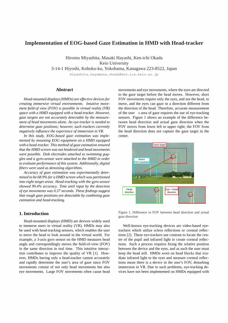
movements and eye movements, where the eyes are directedto the gaze target before the head moves. However, shortFOV movements require only the eyes, and not the head, tomove, and the eyes can gaze in a direction different fromthe direction of the head. Therefore, accurate measurementof the user’s area of gaze requires the use of eye-trackingsensors. Figure 1 shows an example of the difference be-tween head direction and actual gaze direction when theFOV moves from lower left to upper right; the FOV fromthe head direction does not capture the gaze target in thecenter.
Headdirection
Gaze target
Eye + Headdirection
BeforeFOV movement
Figure 1. Difference in FOV between head direction and actualgaze direction
Well-known eye-tracking devices are video-based eye-trackers which utilize sclera reflections or corneal reflec-tions [2]. These eye-trackers use contrast to locate the cen-ter of the pupil and infrared light to create corneal reflec-tions. Such a process requires fixing the relative positionbetween the device and the eyes, and as such the user mustkeep the head still. HMDs worn on head blocks that irra-diate infrared light to the eyes and measure corneal reflec-tions mean there is a device in the user’s FOV, disturbingimmersion in VR. Due to such problems, eye-tracking de-vices have not been implemented on HMDs equipped with

head-trackers.In this study, we adopted the technique of electrooculog-
raphy (EOG) which is widely applied in clinical medicine.EOG is a method for sensing eye movement and is basedon recording the standing corneal-retinal electric potential[2]. We refer to eye-tracking by EOG as EOG-based gazeestimation since EOG cannot track eye movements with ab-solute precision. For EOG-based gaze estimation, disc elec-trodes are placed around the eyes and an electrooculogramis measured. By using this method, the user can move hishead and no eye-tracker devices block the HMD FOV [3].Therefore, we have implemented a HMD to which disc elec-trodes for the EOG and a gyro-sensor for head-tracking areattached. In this study, the accuracy of EOG-based gazeestimation with the HMD was investigated.
This paper is organized as follows. Features of eyemovements and some eye-trackers are explained in section2. Our proposal and the implementation process are ex-plained in section 3, and experiments to evaluate its perfor-mance are described in section 4. Finally, we present theconclusions of our study and discuss future work in section5.
2. Eye Tracking
Eye tracking is a process of measuring either the pointof gaze (i.e. where we are looking) or the motion of the eyerelative to the head. Eye movements provide very importantinformation for estimating the thoughts and intentions ofpersons [4]; the eyes unconsciously turn to objects of atten-tion in the FOV. In addition, eye muscles can move rapidlyand untiringly, and eye. movements are generally catego-rized into saccadic eye movement (saccade) and smoothpursuit eye movement (smooth pursuit) [5].
Saccades are quick, simultaneous movements of botheyes in the same direction and are used when changing gazetargets and staring at speeding objects. In contrast, smoothpursuits are used to maintain gaze on slow objects. Whetherto use saccade or smooth pursuit is an unconscious deci-sion and requires no concentration. All of these featureshas meant that eye tracking has been the topic of study for along time [6]. The measurement device most often used formeasuring eye movements is the eye-tracker, and there aregenerally six types of eye-trackers [2] [7].
2.1. Electrooculography
EOG is a technique for measuring eye movement that isbased on the electric potential of eyes [2]. The cornea ofthe eyeball has positive electric potential with respect to theretina. This electric potential is measured using disk elec-trodes placed on the skin around eyes and the data obtainedis displayed on an electrooculogram.
Transitions on electrooculograms are essentially propor-
tional to the rotation angle of the eyes. Figure 2 shows anoutline of the concept of EOG. One of the advantages ofEOG is that the burden placed on users is small since theonly equipment required for EOG is the small disk elec-trodes that are placed on the user’s face. Additionally, uti-lizing the concept of EOG can make the FOV comfortablewhen using a HMD with the eye-tracker because no cameraand no light for measurement is required. However, vari-ability of the electrooculogram reading depends on manyfactors that are difficult to determine [10]. These perturba-tions are caused by other biopotentials such as those cap-tured by electroencephalography (EEG) and electromiogra-phy (EMG) or are affected by the positioning of the elec-trodes, skin-electrode contacts, lighting conditions, headmovements, blinking, and so on. Consequently, EOG is in-ferior to other eye-trackers in terms of accuracy, and is oftenused only for the measurement of saccades.
Cornea +
Retina -
Disk electrode ++++
Electrooculogram
Disk electrode ----
Eye movementsare calculated
Figure 2. Process of electrooculography
2.2. Optical lever
The optical lever is a method for sensing eye movementusing a light and a contact lens which has a small mirrorfixed on the edge [2]. The reflected light from the mirroris measured by image analysis or photoelectric conversion.This method can track vertical and horizontal eye rotationsof less than 1 degree, and is more accurate than other eye-trackers. Accordingly, the optical lever is often used for re-search on small involuntary eye movements. However, thismethod may need negative pressure to prevent the contactlens from floating and moving, but such negative pressuremay injure the cornea and eye cells. Moreover, measure-ments of the reflected light are limited in scope by the eye-lid. Thus, the optical lever is not suited to measurementsover the long term or for large eye movements.

2.3. Search coil
The search coil is a magnetic sensor that measures eyemovement [2] by using a contact lens which has a coil em-bedded in it and magnets positioned around the eye thatgenerate alternating magnetic fields. Electric currents aregenerated in the search coils through electromagnetic in-duction. The polarity and amplitude of the current gener-ated varies with the direction and angular displacement ofthe eye. By measuring these values, the position of the eyecan be determined. The search coil has similar attributesto the optical lever; it is highly accuracy but places greatburden on users. In comparison with the optical lever, thesearch coil can trim weight off the contact lenses, makingit lighter. This method also measures eye position relativeto the head, and is not generally suitable for point-of-regardmeasurement.
2.4. Scleral reflection
Scleral reflection utilizes the difference between re-flectances of the cornea (the black of the eye) and the sclera(the white of the eye) [2]. The boundary between them isirradiated with infrared light, and a camera in front of theeye captures the light reflected from the eye. The inten-sity of the reflected light varies with the angle of the eyebecause the reflectance of the sclera is stronger than that ofthe cornea. However, irradiating eyes with infrared light hasthe potential to cause eye diseases [8], such as glassblower’s cataracts and eclipse retinopathy.
2.5. Corneal reflection
The method of corneal reflection determines gaze direc-tion by comparing the pupillary position with the reflectionof incident light from the cornea [2] [9]. Typically, this eye-tracking system consists of a single eye-tracker box withan infrared light source to illuminate the eye, an infraredcamera to capture video of the eye which has automatedcamera focus and FOV lens and steering mirrors to trackhead movements. Gaze position is calculated by measuringthe position of the Purkinje image which is visible whenthe cornea is irradiated with a point light source. However,since movement of the head produces a large measurementerror, eye tracking by corneal reflection requires the head tobe kept immobile or measuring devices must be fixed to ahelmet. Additionally, corneal reflection is a risk factor foreye diseases [8].
2.6. Image processing
A technique to measure eye movement by image pro-cessing has been proposed [5]. The measurement con-sists of deriving the pupil or the iris from images of eyesfilmed with a video camera. This technique is easily af-fected by noise such as that generated by the eyelashes and
eyelids. However, high-precision eye-tracking is achiev-able with image denoising. The transaction speed of thistechnique depends on the frame rate of the video camera.Therefore, video cameras whose frame rate is low cannotmeasure high-speed eye movements such as the saccade.
3. Implementation
In this paper, we propose the implementation of EOG-based gaze estimation using a HMD equipped with a head-tracker. The HMD collects measurements of FOV move-ments by using gaze estimation. We adopted EOG for useas an eye-tracker on the HMD since this eye-tracking sys-tem does not obstruct the frame of the HMD, and it allowsthe head to move without burdening the user with mountingdevices for measurements. Our aims are accurate estima-tion of the user’s gaze position and speedy descriptions ofthe FOV in VR when using this device.
We attached a gyro-sensor and disk electrodes to a pairof swimming goggles on the HMD (Figure 3), enablingthe user to easily wear all the necessary devices at onetime. We used SONY’s HMD Glasstron as the base de-vice. Glasstron’s screen provides a physical FOV that is28 degrees in the horizontal and 21 degrees in the verticaldirections. For the gyro sensor to measure head angle, weused INTERSENSE’s InterTrax2USB. InterTrax2USB cap-tures data of the degrees of its triaxial rotation. The use ofthis gyro sensor on the HMD allows for the direction ofthe user’s face to be determined. InterTrax2USB can re-late the head movements to FOV movements in VR in realtime since it runs a description language for VR applica-tions that can connect directly with a PC. Swimming gog-gles and NIHON KOHDEN’s disk electrodes were attachedto the HMD for EOG-based gaze estimation (Figure 4). Thedisk electrodes are firmly glued using NIHON KOHDEN’sElefix electrolyte paste to the swimming goggles in four lo-cations (outer corner of both eyes, and above and below theright eye), making contact (moderate pressure) with the skinaround the eyes. The edges of swimming goggles toucharound eyes and press disk electrodes in moderation. Hor-izontal gaze positions are derived from disk electrodes atthe outer corner of the eyes and vertical gaze positions arederived from the disk electrodes above and below the righteye. With the combined use of EOG with this HMD, wecould accurately determine from the data gathered for bothhorizontal and vertical eye movements where the eyes werelooking. In addition, a disk electrode was placed at theglabella and on both earlobes as ground terminals. Figure5 shows the positions of the disk electrodes. Before use ofthe device, the skin around the eyes was cleaned using anti-septic cotton.
Electrical potentials measured with the HMD wererecorded as an electrooculogram using NIHON KOHDEN’selectroencephalograph Neurofax, and the electrooculogram

Figure 3. Appearance of the HMD used in this study
Figure 4. Disk electrodes and swimming goggles attached to theHMD
1
Ground terminals
Electrooculogram measures
Figure 5. Positions of disk electrodes contacting the skin
was then converted into an estimation of eye movements. Arecording of the electrooculogram was saved as binary data,
and since the data contained noise specific to EOG, a proce-dure was required in which the electrooculogram recordingwas moved using flash memory from the Neurofax to thePC running the gyro sensor and the VR application. Eyegaze information was estimated by synchronizing EOG out-put and the gyro sensor data recording in time. Therefore,measurements of this precision were performed, but a realtime interface with eye movements as triggers was not im-plemented.
To increase the precision of our system, this estimationwas corrected by the use of the filtering algorithms de-scribed. Additionally, calibration was required because theelectrooculograms did not directly describe gaze position.
Firstly, electrooculograms contain noise from the mea-surement environment such as electric current source. Neu-rofax, an electroencephalograph, is equipped with a low-cutfilter (LCF) and a high-cut filter (HCF) to reject such noise.In this study, the low-cut off frequency was set to 0.05 Hz(time constant was 0.008 seconds) and the high-cutoff fre-quency was set to 15 Hz.
Secondly, the electrooculograms are affected by brainwaves and potentials from face muscles. Compared withpotential changes of eye movements, such noise is smallerand higher frequency. We removed the noise using a first-order infinite impulse response (IIR) filter as a low-pass fil-ter (LPF). The behavior of this digital filter is calculatedusing a simple algorithm.
Thirdly, the electrooculograms converged to zero whengaze was maintained on one point for longer than 3 seconds.The convergence was attributed to the LCF of an electroen-cephalograph. Stability of the electric potential by stoppingeye movements reduced the frequency to zero, and it was re-jected by the LCF. Thus, the electrooculogram needs to beadjusted because the convergence causes slippage of gazeestimation. We differentiated the electrooculograms and re-moved derivative values less than a certain value in orderto eliminate convergence. Using this algorithm, potentialvariations associated with eye movements were extracted.However, this algorithm could not handle the more con-stant movements of smooth pursuits, so we limited the eyemovements determined experimentally to saccades. Figure6 shows the processes and the effects of the denoising algo-rithms used.
Eyeblinks induced strong noise on the electrooculo-grams. This was attributed to automatic eye movementsand motion around the eyelid when blinking. The noiseswere generated only in vertical electrooculograms. Thesewere not rejected by the IIR filter and the elimination ofconvergence since eyeblinks have potential variations aslarge as normal eye movements. Thus, vertical saccadeswere difficult to differentiate from eyeblinks. In this study,we avoided this issue by setting blinking times at a fixedtime interval and potential changes were ignored during the

actual eye movement
electrooculogram (filtered by LCF)
filtered by LPF
filtered by LPF & elimination of convergence
Figure 6. Process and effect of filters used
blinking times which were set to avoid drying of the eyes.
In addition, electrooculograms were calibrated with re-gards to the amplitude of the potential to the angle of theeyes. Before using the HMD, the users gazed at four sideedges of the HMD’s frame (leftmost, rightmost, topmostand bottommost) for the calibration. The ratio of the am-plitude and the angle was determined on the basis of thecalibration. All gaze positions were obtained by multiply-ing the ratio obtained from the electrooculograms becauseamplitudes are almost proportional to angles.
4. Experiments
In this study, we implemented EOG-based gaze estima-tion on a HMD with a head-tracker and applied some de-noising algorithms to improve the accuracy of estimation.Additionally, we conducted evaluation experiments to eval-uate the accuracy of the gaze estimation. In experiment 1,the accuracy of EOG used with the HMD was confirmed. Inexperiment 2, the HMD was used to immerse a user in VRand the performances of gaze estimation and head-trackingwere measured. The experimental period was from Decem-ber 25, 2007 to January 9, 2008. Both experiments involved10 participants (9 males, 1 female; mean age 23 years) whowere students of Keio University.
4.1. Experiment 1: Precision of EOG-based gazeestimation
4.1.1 Method
In this experiment, the participants tried to look at targetsone by one as presented by the HMD. The experimentalprocedure was as follows.
1 : Perform calibration
2 : Wait 3 seconds for the next step
3 : Look at a small square displayed in a random positionin the HMD for 3 seconds (Figure 7)
4 : Repeat steps 2 and 3 ten times
The accuracy of EOG was derived from the positionsof the squares and the estimated gaze positions on eachtrial. To compare these positions, the HMD screen waspartitioned equiangularly into several areas from the cen-ter. When the target and the estimated gaze point were inthe same area, it was judged that the estimation was cor-rect. Figure 8 shows an example of correct estimation whenthe screen was partitioned into eight areas. However, theborder lines were not displayed so that the participant couldconcentrate gaze on the targets.
Figure 7. Gaze target displayed on the HMD
4.1.2 Results
Figure 9 shows the result of experiment 1, where accuracyof the EOG-based gaze estimation is shown on the y-axisand the number of the partitions on the x-axis. When therewas a higher number of partitions, the resolution of the esti-mation was high. The graph shows that accuracy decreasedas resolution increased. Gaze-based interfaces are requiredto have around 90% accuracy for ordinary use [11]. If theaccuracy of using the HMD as the interface device is lim-ited to above 90This implies that a HMD system can present

1
Estimated gaze position
Figure 8. Example of correct estimation upon division of thescreen into eight areas
only four choices at the same time. We considered that thereason for such accuracy was the lack of feedback from gazeestimation to the user; the user is not able to check his owngaze position objectively in real time because the estimationis subjected to some filtering by the other PC after measure-ment, and thus the gaze is not fixed on the target because theuser cannot make a clear distinction between the center ofFOV and peripheral vision. In addition, too much pressuremight have been exerted on the participant’s skin around theeyes since the disk electrodes were attached to swimminggoggles on the HMD. In this study, we gaze estimation hadan accuracy of 68.9Thus, in experiment 2 we implementedgaze estimation in eight directions and provided a VR envi-ronment with the HMD.
1
0
20
40
60
80
100
0 5 10 15
Number of the partitions
Accuracy (%)
Figure 9. Accuracy of EOG-based gaze estimation in experiment1
4.2. Experiment 2: Gaze estimation and head-tracking
4.2.1 Method
In experiment 2, the accuracy of EOG-based gaze estima-tion and head-tracking with the gyro-sensor were measured.Additionally, time until input by eye movements and headmovements was measured. We created a VR space with a360-degree view. The space was similar to the inside of abox where all six faces have geometric designs. The mea-surements involved moving the user’s FOV in the VR spacewith the gyro-sensor. The procedure of experiment 2 was asfollows.
1 : Perform calibration
2 : Wait 2 seconds for the next step
3 : Within 5 seconds face a white sphere in a random posi-tion in VR space for one second (Figure 10)
4 : Check the new color of the sphere which is changedrandomly from white
5 : Within 5 seconds look at a square which is the samecolor as the sphere (Figure 11)
6 : Repeat steps 2 to 5 ten times
1
Figure 10. Target of head movement and guide ring at the centerof the screen
Eight differently colored squares were designed as gazetargets (Figure 11) and were displayed at four sides and fourcorners of the screen. The screen was partitioned radiallyinto eight equal areas as in experiment 1. If the estimatedgaze point was in the same area as the target, it was judgedto be correct. The spheres colored in one of eight colorswhich were same as the colors of the gaze targets. In step 3,the participant had to move his head to position the spherein a guide ring at the center of the screen. The margin forerror was two degrees or less of the view angle because the

1
Figure 11. Eight differently colored targets of eye movement
participant was able to face the spheres at the center of FOVwith this margin. In step 5, the participant had to gaze at thecenter of a square which was the same color as the sphere inthe VR space. To help eye movements in the act of gazing,colored arrows were displayed around the guide ring. Weassumed that participants would not gaze at the wrong targetbecause the procedure was designed to be simple and theparticipants had completed some practice trials. At the endof experiment 2, the usability of the HMD was then assessedby questionnaire.
4.2.2 Results
Table 1 shows the performances of EOG-based gaze esti-mation and head-tracking. The accuracy of gaze estimationwas 48.7%, which was lower than the 68.9% accuracy ob-tained in experiment 1.
Figure 12 shows higher accuracy of gaze estimation inthe experiment 2, calculated by scaling the partitioned areaof the screen, and keeping the number of gaze targets ateight. The accuracy of gaze estimation decreased as theresolution increased as in experiment 1. Compared with theresult of experiment 1 however, overall the accuracy is low.These results indicate that gaze estimation was adversely af-fected by head movement or tilt. We surmise that the HMDmoved slightly by its own weight and the inertial force ofthe head movements, thereby shaking impedance betweendisk electrodes and skin due to changes in pressure of theelectrodes attached to the HMD.
The accuracy of the head-tracking with the gyro-sensorwas 99.4This extreme precision may be explained by theuser receiving feedback of head movements in real time.
Time until input in Table 1 shows that EOG estimatedeye movements early. We infer from this result that EOGcan detect transition of the user’s attention from one objectto another ahead of the head-tracker.
Table 1. Performances of gaze estimation and head-tracking
Process Accuracy(%) Time until input(sec)
Gaze estimation 48.7 0.37Head-tracking 99.4 1.74
1
0
20
40
60
80
100
0 5 10 15
Number of the partitions
Accuracy (%)
Figure 12. Accuracy of gaze estimation in experiment 2
Table 2 shows the questionnaire results regarding usabil-ity of the HMD in experiment 2. The questionnaire itemswere answered used a 1-7 Likert scale (1 = strongly dis-agree, 7 = strongly agree). As shown in the table, theintuitive interface of the HMD and immersion in VR arefeatures appreciated by the users. However, the question-naire found that the participants became fatigued with FOVmovements induced by head movements. Questionnaire re-sponses indicated that the fatigue was caused by inclinationof the body and twisting of the upper body. From these find-ings, we can assume that EOG-based gaze estimation doesnot exert harmful, only tiring, influences on the body whenusing head-tracking and experiencing VR space.
Table 2. Usability of the HMD with EOG and head-tracking
Question ValueThe interface was easy to use 5.5The interface was easy to learn 6.4The interface was felt natural to use 6.3The interface was intuitive 6.8The interface did not cause fatigue 2.7I felt immersed in the virtual reality world 6.3It was not uncomfortable being in virtual reality space5.2Using the HMD was enjoyable 6.2

5. Conclusion
A HMD with a head-tracker is an effective device forprovide an immersive VR experience, allowing users tomove their FOV intuitively, and thus contributing to advanc-ing the quality of VR. However, such a HMD does not ac-curately and rapidly show the gaze target in the center of thescreen; an eye-tracker is required to detect the gaze objectaccurately. However, general eye-trackers block the screenof the HMD and restrict head movements.
Against this background, we proposed the implementa-tion of EOG-based gaze estimation using a HMD with ahead-tracker. Additionally, we attached a gyro-sensor anddisk electrodes to swimming goggles fixed to the HMD.
To evaluate performance of this system, two experimentswere conducted. The experiment results revealed that gazeestimation had 68.9% accuracy when the gaze points wereestimated at one of eight partitioned areas. In addition, headmovements caused detrimental effects on the disk elec-trodes, thereby decreasing measurement accuracy. Com-pared to head movements, gaze movements were detectedearly by EOG. While EOG-based gaze estimation did notimpair the usability of the HMD and immersion in VRspace, FOV movements with the head-tracker caused userfatigue.
Approximate gaze areas are detectable by combininggaze estimation and head-tracking. However, advancementof this method of gaze estimation is needed in order for theHMD to be used as an interface device. As future work, wewill improve the method of affixing the disk electrodes aswell as the filtering algorithms used. In addition, we willwork toward the estimation of eye movements in real timein efforts to realize gaze interaction between the user andVR.
6. Acknowledgements
This work is supported by SCOPE (Strategic Informa-tion and Communications R&D Promotion Programme) ofthe Ministry of Internal Affairs and Communications ofJapan.
References
[1] Zeltzer D. Autonomy, Interaction and, Presence.PRESENCE,:vol.1, No.1, pp.127-132, 1992.
[2] The Vision Society of Japan. Visual Information ProcessingHandbook (in Japanese).Asakura Publishing, :2000.
[3] Kuno Y., Yagi T., Fujii I., Koga K. and Uchikawa Y. De-velopment of Eye-gaze Input Interface using EOG.Trans-actions of Information Processing Society of Japan, :Vol.39,No.5, pp.1455-1462, 1998.
[4] Abe K., Ohi S. On a Eye-gaze Input System based on TheLimbus Tracking Method by Image Analysis.The Institute of
Electronics, Information and Communication Engineers Fun-damentals Review, :pp.184, 2001.
[5] Sakashita Y,. Fujiyoshi H. and Hirata Y. Measurement of 3DEye Movements Using Image Processing.Journal of JSEM,:Vol.6, No.3, pp 236-243, 2006.
[6] Daunys G. et al. (2006) D5.2 Report on New Approachesto Eye Tracking. Communication by Gaze Interaction (CO-GAIN), :IST-2003-511598, Deliverable 5.2.
[7] A.T. Duchowski. Eye Tracking Methodology. Theory andPractice.Springer, London, :2002.
[8] Ishihara S. microphthalmus science twenty-two edition (inJapanese).Kanehara, :1991.
[9] Andrew T. D., Eric M., Anand G., Brian M. and Santosh N.Binocular Eye Tracking in VR for Visual Inspection Training.ACM VRST, :pp1-8, 2006.
[10] Ota T., Itakura N., Sakamoto K. and Hirose T. Eye-gazeinput interface by using AC amplified EOG.Technical Reportof IEICE, :Vol.103, No.522, pp37-42, 2003.
[11] Ito K., Sudoh Y. and IFUKUBE T. Eye Gaze Communi-cation System for People with Severe Physical Disabilities.The transactions of IEICE. D-I, :Vol.83-D1, No.5, pp495-503,2000.