Implementation of an FM Radio Station to Facilitate Remote ...
10
International Journal of Engineering Trends and Technology Volume 69 Issue 10, 118-127, October, 2021 ISSN: 2231 – 5381 /doi: 10.14445/22315381/IJETT-V69I10P215 ©2021 Seventh Sense Research Group® This is an open access article under the CC BY-NC-ND license (http://creativecommons.org/licenses/by-nc-nd/4.0/) Implementation of an FM Radio Station to Facilitate Remote Education in the District of Cojata Walther Calvo-Niño 1 , Brian Meneses-Claudio 2 , Alexi Delgado 3 1 Bach.&Facultad de Ciencias e Ingeniería&Universidad de Ciencias y Humanidades 2 Mg.&Image Processing ResearchLaboratory (INTI-Lab) &Universidad de Ciencias y Humanidades 3 Dr.&MiningEngineeringSection&Universidad de Ciencias y Humanidades 1 [email protected], Lima-Perú, 2 [email protected], Lima-Perú, 3 [email protected], Lima-Perú Abstract — INEI affirms that in 2020 6.7% of the student population of Regular Basic Education (RBE) belonging to rural areas did not access any type of distance education implemented by the Ministerio de Educación (MINEDU) due to social isolation by the National Emergency by the COVID- 19. That is why the research work is proposed, which consists of providing coverage with a radio signal in modulated frequency (FM) to the towns that belong to the district of Cojata-Puno and other beneficiaries, to retransmit information related to virtual education denominated “Aprendo en Casa” that is transmitted by web, radio, and television in national channels. In this project, the satellite signal of National Radio of Peru will be used to broadcast the audio programs through the modulated frequency signal, for which studies were first carried out to raise the profile of the project, which consists in obtaining the geographical coordinates and the elevation profile to determine the free space for the propagation of the radio frequency signal and to verify the broad coverage of the signal in the strategic areas, for the location of the places, the different simulations with the support of radio Mobile software, Google Earth and MMANA-GAL, obtaining favorable line-of-sight results with 100% of the first Fresnel zone cleared with respect to the Kantati Ururi community with a reception level of -49.7 dBm which means a high hearing level at the receiver. It is concluded that it is possible to provide a radio signal using FM. Keywords - Radiofrequency; Fresnel zone; rated power; coverage; effective power; impedance; coupling; electric field. I. INTRODUCTION According to Supreme Decree number 044 of the Presidency of the Council of Ministers (PCM) of 2020, in the face of health emergency situations, the government declared a state of national emergency due to the serious circumstances that affect the life of the Nation as a result of COVID- 19.[1]This measure prevented all schoolchildren in Regular Basic Education (RBE) from returning to schools, and as an initiative, the Ministerio de Educación implemented strategies of a remote education called “Aprendo en Casa” through the web, radio, and television platforms. [2] In the report of the Instituto Nacional de Estadística e Informática(INEI), it indicates that in 2020, 94.2% of the population between 6 and 11 years of age enrolled in some grade of primary education received distance classes using some communication technology and Information that included the use of television, radio, and Internet, furthermore, reports that 94.5% of the population between 6 and 11 years old in urban areas and 93.3% in rural areas accessed this type of study.[3] According to the newspaper La República, in the department of Puno, it is estimated that 35% of primary school students do not have access to any type of communication medium, specifically from the Kantati Ururi community of the Cojata district, Huancané province, such as an alternative, some primary-level schoolchildren chose to walk several kilometers towards the top of the KataniJincho hill located 5 kilometers from the community to receive the signal from a station and listen to the classes offered by the Ministerio de Educación.[4] In [5], they carried out on educational radio programs and their influence on the behavior of students, so, statistical tests were applied to a population of 357 students from the Manuel Quintana Miranda elementary school in the province of Los Ríos-Ecuador, surveys were applied to 100 participants, obtaining the following result: 47% of school students listen to the radio in the morning, 43% in the afternoon and 10% at night, arriving at the conclusion that educational radio programs are beneficial for students because they are considered a mass communication means with reach to all people without distinction of social position, which affects the quality of life and the behavior of the population. In [6], they indicate the experiences of social and cultural impacts of Radio in educational communities. The research focused on four educational communities; data collection techniques, observation, interviews, and documentary analysis were applied. As a result, indicate that the implementation of school radio favored the integration of Latin American immigrant students with diverse customs and cultures through the interaction of radio productions with topics of social interest, it also allowed them to recognize
Transcript of Implementation of an FM Radio Station to Facilitate Remote ...

International Journal of Engineering Trends and Technology Volume 69 Issue 10, 118-127, October, 2021 ISSN: 2231 – 5381 /doi:10.14445/22315381/IJETT-V69I10P215 ©2021 Seventh Sense Research Group®
This is an open access article under the CC BY-NC-ND license (http://creativecommons.org/licenses/by-nc-nd/4.0/)
Implementation of an FM Radio Station to Facilitate
Remote Education in the District of Cojata
Walther Calvo-Niño1, Brian Meneses-Claudio2, Alexi Delgado3
1Bach.&Facultad de Ciencias e Ingeniería&Universidad de Ciencias y Humanidades 2Mg.&Image Processing ResearchLaboratory (INTI-Lab) &Universidad de Ciencias y Humanidades
3Dr.&MiningEngineeringSection&Universidad de Ciencias y Humanidades
[email protected], Lima-Perú, [email protected], Lima-Perú, [email protected], Lima-Perú
Abstract — INEI affirms that in 2020 6.7% of the student
population of Regular Basic Education (RBE) belonging to
rural areas did not access any type of distance education
implemented by the Ministerio de Educación (MINEDU) due
to social isolation by the National Emergency by the COVID-
19. That is why the research work is proposed, which
consists of providing coverage with a radio signal in modulated frequency (FM) to the towns that belong to the
district of Cojata-Puno and other beneficiaries, to retransmit
information related to virtual education denominated
“Aprendo en Casa” that is transmitted by web, radio, and
television in national channels. In this project, the satellite
signal of National Radio of Peru will be used to broadcast
the audio programs through the modulated frequency signal,
for which studies were first carried out to raise the profile of
the project, which consists in obtaining the geographical
coordinates and the elevation profile to determine the free
space for the propagation of the radio frequency signal and to verify the broad coverage of the signal in the strategic
areas, for the location of the places, the different simulations
with the support of radio Mobile software, Google Earth and
MMANA-GAL, obtaining favorable line-of-sight results with
100% of the first Fresnel zone cleared with respect to the
Kantati Ururi community with a reception level of -49.7 dBm
which means a high hearing level at the receiver. It is
concluded that it is possible to provide a radio signal using
FM.
Keywords - Radiofrequency; Fresnel zone; rated power;
coverage; effective power; impedance; coupling; electric
field.
I. INTRODUCTION
According to Supreme Decree number 044 of the
Presidency of the Council of Ministers (PCM) of 2020, in the face of health emergency situations, the government declared
a state of national emergency due to the serious circumstances
that affect the life of the Nation as a result of COVID-
19.[1]This measure prevented all schoolchildren in Regular
Basic Education (RBE) from returning to schools, and as an
initiative, the Ministerio de Educación implemented strategies
of a remote education called “Aprendo en Casa” through the
web, radio, and television platforms. [2]
In the report of the Instituto Nacional de Estadística e
Informática(INEI), it indicates that in 2020, 94.2% of the
population between 6 and 11 years of age enrolled in some
grade of primary education received distance classes using
some communication technology and Information that
included the use of television, radio, and Internet,
furthermore, reports that 94.5% of the population between 6 and 11 years old in urban areas and 93.3% in rural areas
accessed this type of study.[3]
According to the newspaper La República, in the
department of Puno, it is estimated that 35% of primary
school students do not have access to any type of
communication medium, specifically from the Kantati Ururi
community of the Cojata district, Huancané province, such as
an alternative, some primary-level schoolchildren chose to
walk several kilometers towards the top of the KataniJincho
hill located 5 kilometers from the community to receive the
signal from a station and listen to the classes offered by the
Ministerio de Educación.[4]
In [5], they carried out on educational radio programs and
their influence on the behavior of students, so, statistical tests
were applied to a population of 357 students from the Manuel
Quintana Miranda elementary school in the province of Los
Ríos-Ecuador, surveys were applied to 100 participants,
obtaining the following result: 47% of school students listen
to the radio in the morning, 43% in the afternoon and 10% at
night, arriving at the conclusion that educational radio
programs are beneficial for students because they are
considered a mass communication means with reach to all
people without distinction of social position, which affects the
quality of life and the behavior of the population.
In [6], they indicate the experiences of social and cultural
impacts of Radio in educational communities. The research
focused on four educational communities; data collection
techniques, observation, interviews, and documentary
analysis were applied. As a result, indicate that the
implementation of school radio favored the integration of
Latin American immigrant students with diverse customs and
cultures through the interaction of radio productions with
topics of social interest, it also allowed them to recognize

Walther Calvo-Niño et al. / IJETT, 69(10), 118-127, 2021
119
their own possibilities of improving themselves and the
feeling of being part of a group.
In [7], they indicate experiences with radio programs
oriented to education using a methodology of education
through entertainment known as education through drama developed with the intervention of a group of educational and
community radio stations in Bolivia. One of the greatest
experiences of using radio drama to promote citizen values
and social inclusion is that it generated spaces for collective
reflection, dialogue, and debate with listeners. The radio
program “Voces Nuestras” had a successful rating in the
broadcast of the 45-episode radio soap opera called “Ciudad
espesa” with the content of real stories under three thematic
axes: pluralism and human diversity, citizen participation in
democracy, and the right to communication and information.
The program was broadcast through 28 radio affiliates located
mostly in rural areas reaching approximately 200 000
listeners.
The main objective of this research work is to implement
an FM radio station to provide coverage area to the towns of
the Cojata district, Huancané province; the project profile will
be developed using the Google maps application, Google
Earth, and for simulation radio mobile software.
The transmission of information through electromagnetic
waves occurs through the oscillation of electric and magnetic
fields produced by the radio transmitter that, through an
antenna, will produce the propagation of electromagnetic
waves in space, to then be received by a device that will decode the information sent by the transmitter. In addition,
the antenna fulfills an important role that of converting
electrical energy into an electromagnetic wave, which
according to the type and polarization will be used according
to the geographical characteristics of the area, its dimensions
depend on the wavelength of the signal of transmitted radio
frequency that is related to the operating frequency.
The following research work is structured as follows: in
section II, the methodology for transmitting information
through radio frequency signals will be presented, in addition
to presenting block diagrams, location of geographic
coordinates, map reading, and verification of the elevation profile. In section III, the results of the research work will
show the parameters of the systems and the simulations with
the mobile radio software that will allow verifying the line of
sight and their effective performance. In section IV, the
discussions of the research work will be presented. Finally, in
section V, the conclusions on the research work will be
presented, as well as some recommendations and
implementation improvements.
II. METHODOLOGY
In this section, the operation of the stages that makes up
the system for the transmission of the modulated frequency
signal is developed, which consists of the identification of the
system, system process, and finally, the result that includes
the propagation of a frequency modulated carrier wave. The
stages of the system are shown in Figure 1, where the
different processes that generate the high-frequency signal
carrier are indicated to transmit information.
Fig. 1. Flow diagram for the transmission of the
modulated frequency signal
A. System identification
For the implementation of the system, an antenna is
required that meets the appropriate characteristics to be able to operate in the specific workplace, since the propagation of
electromagnetic waves fundamentally depends on this device,
for this case, the Yagi antenna of 4 elements for having a
good bandwidth for their operation, high gain, vertical
polarization, and even radiation directionality, this design is
shown in Figure 2.
Fig. 2. 4-element Yagi antenna

Walther Calvo-Niño et al. / IJETT, 69(10), 118-127, 2021
120
This irradiating element adapts to any frequency to be
transmitted, this parameter being important for the
implementation according to the frequency assignment by the
General Directorate of Telecommunications Authorizations of
the Telecommunications of Ministerio de Transportes y Comunicaciónes (MTC), the governing body in charge of the
spectrum channeling for the official operation of broadcasting
stations.[8].
The characteristics of the antenna are presented in Table I.
TABLE I. CHARACTERISTICS OF THE ANTENNA
Antenna Specifications
Antenna Type Yagi
Polarization vertical
Gain 6.8 dBm
Frequency range 87.5 – 108 MHz
Bandwidth 20 MHz
Impedance 50 ohms
VSWR < 1.3
The antenna presents a radiation pattern that ensures
correct transmission coverage with a signal intensity in a
vertical polarization considering that portable frequency-
modulated receivers have a telescopic antenna generally in a
vertical position, thus facilitating the reception of information
without fading during transmissions. The radiation pattern obtained from the MMANA-GAL simulator can be seen in
Figure 3.
Fig. 3. The radiation pattern of the Yagi Antenna
The location of the antenna is another important factor to
have adequate irradiation of the signal, and it will be carried
out considering the line of sight with the strategic areas to be
covered, for which it is executed using Google Earth
according to the geographical coordinates that are shown in
the following Table II.
TABLE II. GEOGRAPHICAL COORDINATES
Location Coordinates
Latitude Longitude
La Rinconada 14°37'15.54"S 69°26'1.25"O
Kantati Ururi 15°12'3.71"S 69° 9'15.85"O
The transmitter will be located in a place called "La Rinconada" because it is an area that has favorable
conditions and factors to ensure the transmission of
information to the largest possible number of beneficiaries.
The topographic profile is observed in the following Figure
4.
Fig. 4. Topographic profile using Google Earth
To calculate the minimum required size of the tower, an
analysis of the line-of-sight profile has been carried out with
the different points and to guarantee that it exceeds at least
80% of the first Fresnel zone; using as a reference a height of
30 meters.
During the transmission of electromagnetic waves from
the starting point to the receivers, they will suffer increasing losses according to the distance from the receiver; this factor
is known as Free Space Loss (FSL) and is calculated by
applying the following mathematical formula.[9]
FSL (dB) = 20Log10(D) + 20Log10 (f) + 32.4
Where:
D (Km): Distance f (MHz): Operating frequency
B. System process
The use of radiofrequency has been increasingly
innovative due to its application in different fields such as
medicine, meteorology, communications, wireless networks,
Walther Calvo-Niño et al. / IJETT, 69(10), 118-127, 2021
121
broadcasting, etc. Its classification corresponds according to
the frequencies and wavelengths that are present in the bands
of the radioelectric spectrum; in our case, the corresponding
band is the Very High Frequency (VHF) comprised between
30 MHz to 300 MHz. Its length is related to the following
expression: ᨂ =𝑐
𝑓where:
(λ), wavelength (m)
(c), speed of light (m / s)
(f), frequency (Hz)
This indicates that the physical antenna is of a certain
length according to the operating frequency.
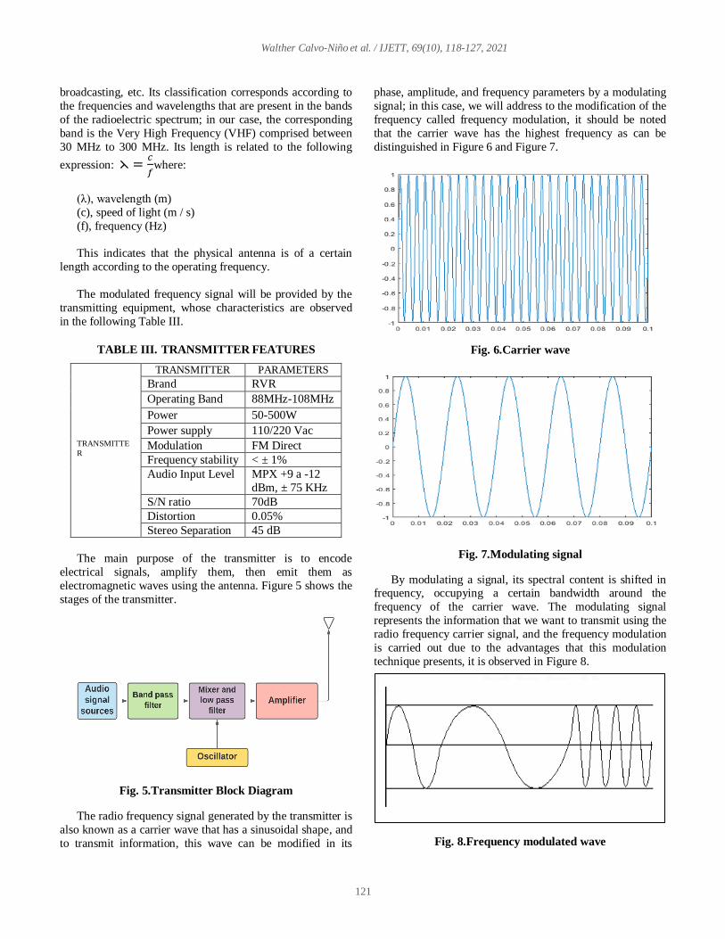
The modulated frequency signal will be provided by the
transmitting equipment, whose characteristics are observed
in the following Table III.
TABLE III. TRANSMITTER FEATURES
TRANSMITTE
R
TRANSMITTER PARAMETERS
Brand RVR
Operating Band 88MHz-108MHz
Power 50-500W
Power supply 110/220 Vac
Modulation FM Direct
Frequency stability < ± 1%
Audio Input Level MPX +9 a -12
dBm, ± 75 KHz
S/N ratio 70dB
Distortion 0.05%
Stereo Separation 45 dB
The main purpose of the transmitter is to encode
electrical signals, amplify them, then emit them as
electromagnetic waves using the antenna. Figure 5 shows the
stages of the transmitter.
Fig. 5. Transmitter Block Diagram
The radio frequency signal generated by the transmitter is
also known as a carrier wave that has a sinusoidal shape, and
to transmit information, this wave can be modified in its
phase, amplitude, and frequency parameters by a modulating
signal; in this case, we will address to the modification of the
frequency called frequency modulation, it should be noted
that the carrier wave has the highest frequency as can be
distinguished in Figure 6 and Figure 7.
Fig. 6. Carrier wave
Fig. 7. Modulating signal
By modulating a signal, its spectral content is shifted in frequency, occupying a certain bandwidth around the
frequency of the carrier wave. The modulating signal
represents the information that we want to transmit using the
radio frequency carrier signal, and the frequency modulation
is carried out due to the advantages that this modulation
technique presents, it is observed in Figure 8.
Fig. 8. Frequency modulated wave

Walther Calvo-Niño et al. / IJETT, 69(10), 118-127, 2021
122
The percentage of modulation is defined as the ratio
between the real frequency deviation and the maximum
frequency deviation allowed by law per 100% [10]. Stereo or
mono systems should not exceed 100% on frequently
recurring peaks. It is expressed as follows:
% modulation =∆f(real)
∆f(max)*100%
The modulation of the transmitter will be carried out
through the satellite link of the National Radio station, a
service that was implemented with the authorization of the
Instituto Nacional de Radio y Televisión del Perú (IRTP)
through Directorial Resolution N° 1095-2020-MTC/28[11].
The satellite to select is Intelsat 11, which is located at
14.63°S 69.44°W. This satellite is the one that provides signal coverage to Europe and America using the C band of
transmission.[12]The following coverage footprint is
observed in Figure 9.
Fig. 9. Intelsat 11 satellite coverage footprint
To make this link, it is necessary to take into account the
location, horizontal displacement, elevation angle, angle with
respect to the horizon, and direction of the receiving antenna
[13]. For our case, the location will be in the same
transmission plant in the place called "La Rinconada," so the
same geographical coordinates will be used, and the satellite
data is observed in Table IV.
TABLE IV. DETAILS FOR SATELLITE SIGNAL
RECEPTION
Description Data
Distance to the satellite 36735 Km.
Location 14.63°S 69.44°W
Elevation angle 55,1°
LNB tilt 59,60°
Azimuth 63,1°
The amplification of the radio frequency signal is to
increase the power to provide signal coverage at greater
distances, for which the transmitter power, the antenna gain,
and the appropriate height are determined.
There are several kinds of radiofrequency amplification, such as class A, class B, class C, class AB. Its design
responds according to individual cases. For our work, class C
amplification will be used to meet the requirements for the
use of the fundamental frequency with the minimum
generation of harmonics.
The coupling of the transmitter and the antenna is
fulfilled under certain parameters such as operating
frequency, antenna length, height above sea level,
impedance, transmission line attenuations, and connectors.
These elements determine the good coupling for an efficient
operation of the transmission system, avoiding losses and
generation of return signals to the final radiofrequency amplification stage, increasing the temperature, and
destroying the power semiconductor. The power
measurement process in transmitters makes it necessary to
create instruments that use special elements such as the
directional coupler, a device that serves to independently
take samples of the incident wave and reflected in a
transmission line, as can be seen in Figure 10.
Fig. 10. High-frequency directional coupler
In a transmission line, the incident wave is the RF signal
generated by the transmitter that propagates from it to the
load or antenna. The reflected wave is the wave returned by
the load towards the transmitter as a consequence of an impedance mismatch, as the load has a different impedance
to the characteristic impedance of the transmission line [14].
These two waves traveling through the transmission line give
rise to a standing wave of current and voltage along the line,
whose relationship between the incident and reflected power
captured by the directional coupler can be analyzed using the
following Table V.

Walther Calvo-Niño et al. / IJETT, 69(10), 118-127, 2021
123
TABLE V. STANDING WAVE RATIO (SWR) AND
ITS INCIDENCE
SWR Reflected power
%
Antenna power
%
Infinity 100 0
17 80 20
9 63 37
6 50 50
3.5 32 68
3 25 75
2.3 16 84
2 10 90
1.4 3 97
1.2 1 99
Mathematical calculations are operated with the
following expression:
𝑆𝑊𝑅 = 1+√
𝑃𝑟
𝑃𝑖
1−√𝑃𝑟
𝑃𝑖
[15]
Where:
SWR = Standing Wave Ratio.
Pi = Incident power in antenna. Pr = Power reflected in antenna.
Next, the calculation of the Apparent Radiated Power
(ARP) will be carried out considering the losses caused by
the different elements in the path until the power is delivered
to the antenna; it is calculated through the following equation
taking as a reference the indicated transmitter power in Table
III.
Where:
ARP = Apparent Radiated Power
Pi = Incident power in antenna. Pr = Power reflected in antenna
Pn = Nominal power of the transmitter
ALTx = Transmission line
Ac = connectors
ARP=150 Watts (w)
ARP = (Pi-Pr)*𝐺𝑎𝑛𝑡𝑒𝑛𝑎[13]
To find the Reflected Power (Pr), the following
expressions must be calculated:
𝑉𝑆𝑊𝑅 =1+ (
𝑃𝑟
𝑃𝑖)
12
1− (𝑃𝑟
𝑃𝑖)
12
[13]
Making a change of variable z=(𝑃𝑟
𝑃𝑖)
1
2, we obtain that:
VSWR = 1+𝑍
1−𝑍
Solving for Z (1-Z) *VSWR =1+Z
VSWR-Z* VSWR=1+Z
VSWR-1=Z+Z* VSWR VSWR-1=K (1+ VSWR)
Z=𝑉𝑆𝑊𝑅−1
𝑉𝑆𝑊𝑅+1
Knowing the antenna standing wave ratio (VSWR) = 1.3,
we obtain:
Z=1.3−1
1.3+1
Z=0.3
2.3
Now squaring and doing the division:
𝑍2 = (0.3
2.3) 2
𝑍2 = 0.0170132
Then:
Pr = Pi*0.0170132
Replacing in the equation:
PRA = (Pi-Pr) *G antenna PRA = (Pi-Pi*0.0170132) *1
PRA = Pi (1 - 0.0170132)
Pi = 𝑃𝑅𝐴
1 − 0.0170132
Pi = 152.596W
Converting this value to dBw:
P(dBW) = 10. log10 (𝑝(𝑊)
1𝑊)
P(dBW) = 10. Log10 (152.596
1𝑊)
P(dBW) = 21.83543 dBw
Then: Pi = Pn – ALTx – Ac
Pn = Pi + ALTx +Ac
Pn = 21.83543 dBw + 0.1701dB + 0.04dB
Pn = 22.40553 dBw
Pn = 174. 001503W
With the value of the nominal power of the transmitter
(Pn), the tolerance of 2% provided by the manufacturer must
be considered; this will make the nominal transmission
power be within the limit values of:
Pn – 2% ≤ Pn ≤ Pn + 2% 174, 001503 -2% ≤ Pn ≤ 174, 001503 + 2%
170.521472W ≤ Pn ≤ 177,4815W
With the nominal power, ARP is calculated in each case,
and it must be verified that the result is within the tolerance
range of 10% of the ARP value allowed by the Ministerio de
Transportes y Comunicaciones (MTC). [10]
135W ≤ PRA ≤ 165W

Walther Calvo-Niño et al. / IJETT, 69(10), 118-127, 2021
124
Taking the value of the nominal power of the transmitter:
Pn max = 177,4815W = 22,4915 dBw
Pn max ≤177,4815W
Pi = Pn max – ALTx – Ac
Pi = 22.4915 dBw – 0.1701dBm – 0.4dBw = 21.9214dBw Pi = 155, 6467W
Pr = 𝑧2*Pi
Pr = 0.0170132*155, 6467W
Pr = 2.64804W
ARP= (Pi - Pr) *𝐺𝑎𝑛𝑡𝑒𝑛𝑎
ARP = (155, 646W – 2.64804) *1
ARP = 152.997W
Taking the minimum value of the transmitter's nominal
power:
Pn min = 170.5214W = 22,3177 dBw
Pn max ≥ 170.5214W
Pi = Pn max – ALTx -Ac
Pi = 22, 3177 dBw – 0.1701dBw – 0.4dBw = 21.7476
Pi = 149,5409
Pr = 𝑧2*Pi
Pr = 0.0170132*149,5409w
Pr = 2.54416W
ARP = (Pi -Pr) *𝐺𝑎𝑛𝑡𝑒𝑛𝑎 ARP= (149.5409w – 2.54416) *1
ARP =146.9968w
With the previous calculations, it is revealed that, for a
nominal power of the transmitter of 150W and with a
tolerance of ± 2%, the maximum and minimum margin of the
apparent power is within limits established by the MTC.[10]
135W ≤ PRA ≤ 165W
146.9968W ≤ PRA ≤ 152.997W
The value to be taken as our apparent radiated power will
be the data that we will have to use in dB.
ARP (dBm) = 10 log (150𝑊
1𝑚𝑊 )
ARP (dBm) = 51.76dB
The proper use of the mentioned elements will make it
possible for the power amplification stage to comply with its
normal operation within the established parameters, and therefore at a normal temperature below 50°C. If for any
reason, it exceeds 50°C, the alarms will be activated, and the
equipment will automatically turn off.
III. RESULTS
To obtain the results, the Radio Mobile software is used,
which allows us to carry out the simulation of the transmitter
and receiver according to the established parameters of the
different elements used for the propagation of the radio
frequency signal. In addition, the different parameters
obtained in the simulation will be analyzed to be able to
contrast with physical equipment. The radiation power is
shown through the heat map, whose signal coverage is
represented by colors, the red color being a high-level signal
of -66dBm, the signal coverage of the different areas such as
the district of Cojata, the province of San Nicolas de Putina,
the Kantati ururi community and many other neighboring towns that will also benefit from the radio broadcasting
service and we can see it in Figure 11.
Fig. 11. Radiofrequency propagation heat map
To determine the appropriate level of reception, the
classification ranges of the audible quality of the received
signal are shown, as can be seen in Table VI.
TABLE VI. AUDIBLE SIGNAL
Signal quality Range
Low -75dBm- ∞
Medium -70dBm- -74dBm
High -69dBm and higher
In this simulation, which corresponds to the matrix located in the city called “La Rinconada” with respect to the town of
Kantati Ururi, it is possible to observe and analyze the propagation of the radio frequency signal that transmits with a nominal
power of 500W in frequency modulated at a distance of 71 km, the effective radiated power (PER) has a level of 680W and the
equivalent isotropic radiated power (EIRP) of 1.12 Kw, very good levels that indicate a transmission in optimal conditions. In
addition, the topographic profile does not show high reliefs between the Transmitter and Receiver; there is a line of sight,

Walther Calvo-Niño et al. / IJETT, 69(10), 118-127, 2021
125
registering as the worst Fresnel equal to 1.0F1, which means 100% of the first Fresnel region is free of obstructions, thus
allowing that the system has an adequate reception signal with a level of - 49.7dBm, being located at the level of high audible
signal quality, as can be seen in the following Figure 12.
Fig. 12. Propagation of the electromagnetic wave from the “La Rinconada” transmission plant to the town of Kantati
Ururi
A second simulation can also be observed, which corresponds to the transmission plant with respect to the district of
Cojata, with the following results: the worst Fresnel zone equal to 0.7F1, indicating that 70% of the first Fresnel zone is free of
obstructions and is within the allowed ranges, since at least 60% clear is required of the first Fresnel zone to obtain an adequate
reception signal, as shown in Figure 13.
Fig. 13. Propagation of the radio frequency signal from the Transmission plant to the district of Cojata

Walther Calvo-Niño et al. / IJETT, 69(10), 118-127, 2021
126
The sensitivity of the receiver determines the level of the
weakest signal that the receiver is capable of receiving with
an acceptable reproduction of the original modulating signal;
in the following Figure 14, the threshold of the receiver is
observed.
Fig. 14. Receiver sensitivity threshold
The coverage area of this radio station is aimed at signal coverage to the Kantati Ururi community and its
surroundings, as shown in the figure on the heat map.
According to the analysis of the simulations, they indicate
that the field intensity is reaching different areas mentioned
in a value greater than 46.9 dBuV/m, demonstrating adequate
signal reception as shown in Table VII.
TABLE VII. SIGNAL QUALITY IN STRATEGIC
AREAS
Zones Signal quality Power levels
(dBm)
Kantati Ururi High -49.7
Cojata High -49.3
Putina Medium -68.6
IV. DISCUSSIONS
The research work [6]confirms that the use of radio
communication media influences the cultural development of
the inhabitants of rural areas where they have conventional
devices of common use, such as the radio receiver, that is
why this Research work presents an alternative method for
the propagation of frequency signal modulated by the similar
characteristics that our country presents due to the digital
divide that mainly presents rural areas, so access to
information is essential as part of social development and
culture.
In [5], he considers that the Radio broadcast signal is an alternative to seek a change in behavior and an improvement
in the quality of life, as it is a means of communication
within reach of large groups, especially the population with
limited economic resources.
In the simulations carried out, the height of the receiving
antenna at a level of 1 meter was considered in comparison
with the studies carried out by the antecedents. Otherwise, it
is shown in [6]that for the simulation subjects, it places 20
meters in height in the receiving antenna, the simulation
being far from reality.
The geographical characteristics of the area are rugged,
so a detailed study must be carried out based on simulation software, which is not carried out in [7]because they pose up
to a limit level of 60% free of the first Fresnel zone, which in
our case was raised 80%.
In addition, the research work is oriented to the needs of
the population with the peculiarity that it has the
implementation of a receiver that will be linked to the
satellite signal of the Instituto Nacional de Radio y
Televisión del Perú (IRTV), which will avoid costs incurred
in maintaining a transmission booth to broadcast live
programs.
V. CONCLUSIONS
It is concluded that the radio is a means of social
communication that is within reach of the great majority, so
it facilitates the transmission of information, especially to the
rural population with scarce economic resources. The simulation through the software is essential because
it allows determining effective communication through the
line of sight and the reading of the parameters.
Keep in mind the Norms that regulate
Telecommunications in our country when carrying out the
implementation of Broadcasting projects.
It is concluded that the importance of simulation prior to
implementation will help to visualize the characteristics of
the antenna, as well as the Fresnel zone, the effective
radiation power, and the reception signal level.
REFERENCES [1] P. S.D. No. 044-2020, Supreme Decree No. 044-2020-PCM, vol. 0, no.
0, p. 0, 2020, [Online]. Available:
https://www.gob.pe/institucion/pcm/normas-legales/460472-044-2020-
pcm.
[2] [Minedu, Vice Ministerial Resolution No. 088-2020-MINEDU, 0,
0(0)(2020) 0, [Online]. Available:
https://www.gob.pe/institucion/minedu/normas-legales/466186-088-
2020-minedu.
[3] INEI, 94.2% of the population aged 6 to 11 enrolled in primary
education received virtual classes, 0(0) (2020) 0, [Online]. Available:
https://www.inei.gob.pe/prensa/noticias/el-942-de-la-poblacion-de-6-a-
11-anos-de-edad-matriculares-en-educacion-primaria- received-virtual-
classes-12384 /.
[4] La República, Puno: Children climb hills to listen to the radio and
receive classes, 0(0) (2020) [Online]. Available:
https://larepublica.pe/sociedad/2020/05/10/en-puno-ninos-escalan-
cerros-para-escuchar-radio-y-recibir-clases-aprendo-en-casa-lrsd/.
[5] K. A. Apraez Pérez, Educational radio program and its impact on the
behavior of students at the Dr. Manuel Quintana Miranda Basic
Education School., Final Report DEL Proy. I investigated. PRIOR TO
OBTAINING THE Tit. LICENSED IN Comun. Soc., 0(0) (2017) 3–
92, [Online]. Available:
http://dspace.utb.edu.ec/bitstream/handle/49000/3552/P-UTB-FCJSE-
CSOCIAL-000060.pdf?sequence=1&isAllowed=y.
[6] J. L. Aguirre Alviis, Bolivian radio in the long journey of educating by
telling stories: the case of the program‘ Voces Nuestro, Rev. Cienc.
and Cult., 0(0) (2016) 83–103, [Online]. Available:

Walther Calvo-Niño et al. / IJETT, 69(10), 118-127, 2021
127
http://www.scielo.org.bo/scielo.php?pid=S2077-
33232016000100004&script=sci_abstract.
[7] E. Solas et al., Social and cultural impacts of the‘ La Radio en la
Escuela ’program in the southern area of Greater Buenos Aires, Rev.
Académica la Fac. Ciencias Soc., 0(0) (2020) 85-109.
[8] F. Paz Quiroz, Supreme Decree that modifies the Regulations of the
Radio and Television Law, approved by Supreme Decree No. 005-
2005-MTC, Lima, (2016).
[9] A. M. Barragán Medina, Development of an application for the
calculation of radio links applying the wideband pcs microcell model
in matlab., Quito Ecuador, (2020).
[10] Ministry of Transportation and Communications, Ministerial
Resolution No. 358-2003-MTC / 03 | Government of Peru, Technical
Standards for Broadcasting Service, (2005).
https://www.gob.pe/institucion/mtc/normas-legales/10220-358-2003-
mtc-03.
[11] F. Paz Quiroz, TV Peru is authorized to provide satellite broadcasting
service to reach more remote areas, Lima, Sep. (2020).
[12] Intelsat, “SatBeams - Satellite coverage maps - Intelsat 11 (IS-11,
PAS-11) / Intelsat 32e (IS-32e, SKY Brasil-1, Sky-B1) satellite
footprint,” 2011. https : //satbeams.com/footprints? beam = 5703.
[13] A. Lopez Faustino and Ramirez Falla Nicolas, Technical proposal for
the design of an FM and IP radio station at the Santo Tomás University
Tunja headquarters, (2018).
[14] Campos Rojas Javier and Rodriguez Deykel Omar, Impedance
coupling in RF amplifiers, reflected wave, effects and power
calculation, (2017), [Online]. Available:
https://d1wqtxts1xzle7.cloudfront.net/57241736/Paper_R.pdf?1535133
064=&response
[15] Chero Salazar Andrés, Optimization of antennas to transmission lines
using Smith chart and 4NEC2 software, Universidad Nacional de
Piura, Piura-Peru, (2018).