
Implementation of an Analog Multiplexer for Xilinx Nexysjharris/research/... · ·...
43
Implementation of an Analog Multiplexer for Xilinx Spartan 3e Starter Board by Frank Scarfo Senior Project COMPUTER ENGINEERING DEPARTMENT California Polytechnic State University San Luis Obispo 2009
Transcript of Implementation of an Analog Multiplexer for Xilinx Nexysjharris/research/... · ·...

ImplementationofanAnalog
MultiplexerforXilinxSpartan3e
StarterBoard
by
FrankScarfo
SeniorProject
COMPUTERENGINEERINGDEPARTMENT
CaliforniaPolytechnicStateUniversity
SanLuisObispo
2009

i
TableOfContents
ListofFigures....................................................................................................................................... iiAcknowledgements ..........................................................................................................................iiiI. Introduction .................................................................................................................................. 1II. Background.................................................................................................................................. 2III. Requirements ............................................................................................................................ 5IV. DesignandDevelopment...................................................................................................... 6AnalogMultiplexerHardware.................................................................................................. 6AnalogMultiplexerSoftwareInterface ................................................................................ 7ExternalStorageSystemDesign ............................................................................................. 8
V. SystemTesting......................................................................................................................... 14CurrentStateofSystem ........................................................................................................... 15
VI. Conclusion................................................................................................................................ 19VII. Bibliography .......................................................................................................................... 21VIII. Appendix................................................................................................................................ 22A.MUX.h–MUXControlAlgorithmHeaderFile ........................................................... 22B.MUX.c–MUXControlAlgorithmSourceCode.......................................................... 22C.Lcd.h–LCDControlHeaderFile ..................................................................................... 23D.LCD.c–LCDControlSourceCode................................................................................... 24E.Timer.h–TimerControlHeaderFile ............................................................................ 28F.Timer.c–TimerControlSourceCode........................................................................... 28G.Leds.h–LEDControlHeaderFile................................................................................... 29H.main.c–SampleControlAlgorithmSourceCode.................................................... 29I.spi.h–SPIControlHeaderFile.......................................................................................... 32J.spi.c‐SPIControlSourceCode ......................................................................................... 33K.EmbeddedSystemBlockDiagram................................................................................. 37L.AnalysisofSeniorProjectDesign ................................................................................... 38

ii
ListofFigures
Figure1:Spartan3EStarterBoard ............................................................................................ 3
Figure2:SimplifiedAnalogMultiplexerHardwareLayout ............................................. 7
Figure3:DigilentPMOD‐SDSecureDisk(SD)CardModule ........................................... 9
Figure4:SDCardSPIModeInitializationSequence........................................................ 10
Figure5:SampleSuPERMemoryInterface ......................................................................... 11
Figure6:DigitalOutputsMemoryDetail .............................................................................. 11
Figure7:SampleControlAlgorithmSoftwareFlow ........................................................ 12
Figure8:DigilentPMOD‐SF16MegabitSerialFlashROM............................................ 17

iii
Acknowledgements
IwouldfirstliketothankProfessorJamesHarrisforallowingmetotake
partinsuchaninterestingproject,andforhissupportandguidancealongthe
way.IwouldalsoliketothankMattStaniszewskiandKhanhNguyenfortheir
assistanceindevelopingembeddedsystemsfortheSpartan3eBoard.Finally,I
wouldliketothankTonyWonsyld,whoseproofofconceptofanAnalog
MultiplexerfortheSuPERsystemprovidedasolidfoundationtoimplementmy
system.

1
I. Introduction
TheCalPolySustainablePowerforElectricalResources(SuPER)project,
startedbyProfessorJamesHarrisin2005,soughttoprovidealow‐costmethod
ofprovidingpowertopeopleindevelopingcountries.Thesecountriesoftenlack
thebasicnecessitiestosupporttheirday‐to‐dayoperations.Theystruggleto
providethesimpleamenitiessuchaslighting,waterpumps,refrigeration,and
powertorunvarioustoolsthatweoftentakeforgranted.Insteadofwaitingfor
governmentsandlargecorporationstoprovidethisnecessaryinfrastructure,
theSuPERprojectaimstoprovideasustainable,costeffectivesolutionfora
singlefamilyorvillagetopurchaseindependently.
Inrecentyears,aprototypehasbeendeveloped,whichcenterson
harnessingsolarenergytoprovidepowertonumerousloads.Thisprototypeis
constantlybeingimprovedtoreducecosts,improveefficiency,andextendthe
system’soperationallifetime.Whilethecostofnewtechnologiesthatarebeing
usedtodevelopthissystemremainfairlyhigh,inthenearfuturethesecostsare
expectedtodropsignificantlyastechnologiesandconstructionmethods
improve.

2
II. Background
CurrentlytheSuPERprototypeconsistsofaphotovoltaicpanelthatisusedto
chargeabattery,whichinturnisusedtopowerseveralDCloadsincluding
motors,refrigerationunitsandlightingsystems.Thiscomplexsystemrequires
precisecontroltoregulatehowthebatteryischargedanddischarged.This
intricatecontrolallowsforlongerbatterylifetimes,andsafelyregulatesthe
loads.
Inthepast,theSuPERprototypewascontrolledusingaDelllaptopandaPIC
Microcontroller.Whilethissystemisabletoexceedtherequirementsofthe
system,itisexpensivetoimplement,anddrawsalargeamountofpower
(approximately60watts).Itbecameclearthatalowcost,lowpowersolution
wasrequirediftheSuPERprojectwastoreachit’sgoalofbeingaffordablefor
thecommonfamilyinanunderdevelopedcountry.
Afteranalyzingseveraloptions,itwasconcludedthattheXilinxSpartan3e
StarterBoard(seeFigure1)supportedmanyoftherequirementsforcontrolling
theSuPERproject,andcostslessthatonehundredandfiftydollars.Notonly
doesthissignificantlycutoverallsystemcost,butalsoreducesthepowerusage
toonlyaboutonewatt.AfterrealizingthevalueofswitchingtotheSpartan3e
board,thecorestepsofimplementingthesystemweredeveloped.These
includedanembeddedLinuxdistributioncalleduClinuxtorunontheFPGA,and

3
applicationstotakeinputfromakeyboardandoutputtoadisplay.These
projectsformthefoundationonwhichtheSuPERcontrolsystemwillrun,but
stilllacksomefunctionalitytomeetalloftheneedsoftheprototype.
Figure1:Spartan3EStarterBoard
Inordertoimplementthesemissingcapabilities,twosystemsneededtobe
developed,thefirstofwhichbeingawaytomultiplextheinputsandprovidethe
appropriateoutputs.TheSpartan3eFPGAoffersalimitednumberofpinstobe
usedasinputsandoutputs,farlessthatrequiredtomanagealloftheswitches

4
andsensorsnecessarytocontroltheSuPERprototype.Tocombatthisproblem,
TonyWonsyldprovedthatitwaspossibletomultiplexthenumeroussystem
inputsthroughtwoanalogmultiplexers.Thisdrasticallyreducesthenumber
pinsrequiredfromover50downto20(5SPIsignals,4multiplexerselectlines,
10digitaloutputs,and1PWMoutput).
Thissystemmadeuseoftheonboardflashmemorytostorethetime
stampedinputdata.ThismemoryhoweverwillbeoccupiedbytheuClinux
installationontheboard,makingitnecessarytointegrateanewmemorydevice
tothesystem.Thisdataisextremelyvaluableforbothperformanceanalysisand
failurediagnosis,andanalternativestoragemethodwillneedtobedeveloped.

5
III. Requirements
ThisprojectexpandsonTonyWonsyld’sprojecttoimplementtheanalog
multiplexerdesignhepreviouslyvalidated.Thissystemissubjecttoseveral
strictrequirements:
• Systemmustbeabletosupportupto32inputstoallowforinclusionof
additionalsensorsofcurrentsystem
• SystemmustbeabletooutputappropriatePWMandapproximately10
digitalcontrolsignals
• Systemmustreacttoharmfulloads(suchascurrentoverload)withinone
millisecond
• LogandDisplayappropriatesystemfeedback
• Performallrequirementswithinonetenthofasecond.

6
IV. DesignandDevelopment
Thedesignofthissystemtookplaceinseveraldistinctparts.Theseincluded
developingthehardwaretocontroltheanalogmultiplexers,creatingasimple
softwareinterfacetothemultiplexers,designingawaytostoredata,and
implementingasamplecontrolalgorithmtodemonstratethesystem
capabilities.
AnalogMultiplexerHardware
Thefirststepinintegratingtheanalogmultiplexerswastolayoutthe
hardwareforthesystem.ThiswasdoneonaDigilentFX2Breadboard,which
connectsintotheon‐boardFX2connector.Thisboardprovidesaquick,simple
waytolayoutandmodifythehardwareandinterfaceitwiththeSpartan3e
Board.Thehardwareisfairlysimpletoimplement,andrequiresveryfewpins.
FourpinsareusedtocontrolwhichsignalsarebeingpassedthroughtheMUX,
and5pinsareusedtocontrolbothoftheanalogtodigitalconverters.

7
Figure2:SimplifiedAnalogMultiplexerHardwareLayout
AnalogMultiplexerSoftwareInterface
Afterthehardwaredesignwascomplete,itwasnecessarytoprovidea
simpleinterfacetocontrolbothMUXsandADCstoreadinthesensorandswitch
data.Thiscontrolwasbrokendownintoseveralfunctions:
voidinitMUX()
Thisfunctionshouldbecalledbeforeanyothercallsaremade.It
initializesalloftheappropriatepinstobeoutputsandinitializesthe
SerialPeripheralInterface(SPI)tocommunicatewiththetwoon‐board
analogtodigitalconverters.

8
voidnextInput()
ThenextInputfunctioncontrolstheMUXselectlinestoiteratethroughto
thenext2sensorsconnectedtoeachMUX.Thisfunctionshouldbe
followedbyacalltoreadInput().
unsignedlongreadInput(intadcNum)
readInputactsasawrappertothefunctionsinspi.ctoallowforasimpler
userinterface.Ittakesasingleargument,whichspecifieswhichADC
shouldbereadfrom.
ExternalStorageSystemDesign
AfterresearchingnumerouspossibilitiesforinterfacingtheSpartan3ewitha
non‐volatileexternalmemorydevice,wedecidedthattheDigilentPMOD‐SD(see
Figure3)wouldbestfitoursystem.ThePMOD‐SDisamodulethatallowsa
SecureDisk(SD)cardtobeconnectedtotwoofthejumpersontheSpartan3e
board.Thisdesignwouldallowfor2GBofeasilyremovablememorythatcould
bepluggedintoaSDcardreadertobeanalyzedonaPC.

9
Figure3:DigilentPMODSDSecureDisk(SD)CardModule
SDcardscanusetwodifferentinterfacesforcommunication:SDcardmode,
andSPImode.Bothofthesemodesarecommandandresponsetypeinterfaces
wherethemastersendsaseriesofbytestothecardspecifyinganactiontobe
performed,thenwaitsforaconfirmation.WhiletheSDcardusesseveraldata
linestocommunicatemakingtransfersmuchfaster,itutilizesamuchmore
complicatedcommunicationprotocol,andcanonlywriteblocksof512bytesata
giventime.Afterensuringtheslowercommunicationspeedwasacceptable,it
wasdecidedthattheSPIinterfacewouldbeused.
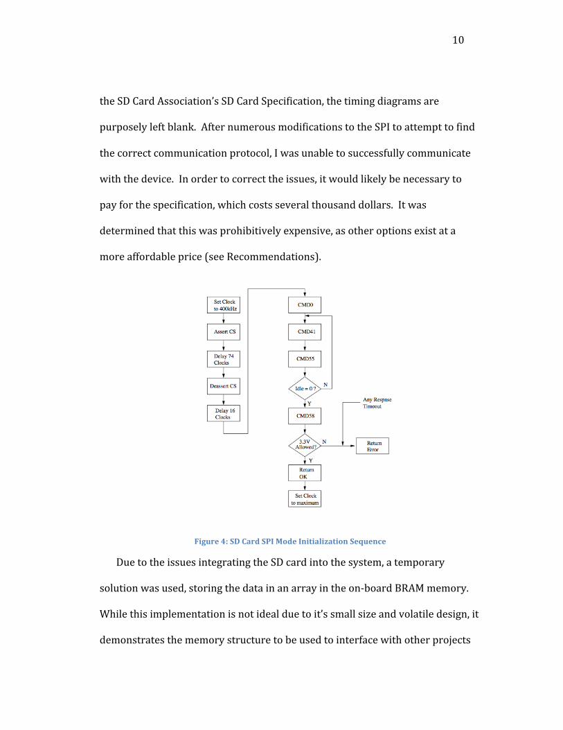
Thefirststepinusingthecardwastoinitializethecard.Thisprocess
involvessendingthecardseveralcommandstocheckthevoltagelevelssupplied
tothecard,transferthecardtoSPImode,andtosetthetransferblocksize(see
Figure4).Thisstepiswheremysystemrepeatedlyfailed,asitwasunabletoget
anyresponsesfromthecardtoverifyitwasreceivingcommands.Aftertesting
theSPIwithanoscilloscopetoverifythatthesignalswerereachingthecard,it
becameapparentthattheissuewasduetotheSPItiming.Inthefreeversionof
10
theSDCardAssociation’sSDCardSpecification,thetimingdiagramsare
purposelyleftblank.AfternumerousmodificationstotheSPItoattempttofind
thecorrectcommunicationprotocol,Iwasunabletosuccessfullycommunicate
withthedevice.Inordertocorrecttheissues,itwouldlikelybenecessaryto
payforthespecification,whichcostsseveralthousanddollars.Itwas
determinedthatthiswasprohibitivelyexpensive,asotheroptionsexistata
moreaffordableprice(seeRecommendations).
Figure4:SDCardSPIModeInitializationSequence
DuetotheissuesintegratingtheSDcardintothesystem,atemporary
solutionwasused,storingthedatainanarrayintheon‐boardBRAMmemory.
Whilethisimplementationisnotidealduetoit’ssmallsizeandvolatiledesign,it
demonstratesthememorystructuretobeusedtointerfacewithotherprojects

11
suchasthedataparserdevelopedbyKhanhNguyen.Thisinterfaceisdesigned
toefficientlyutilizethelimitedspaceavailablebynotstoringtimestamps.
Instead,thedataisstoredinconsecutiveblocksof68bytes,twobytesforeachof
the32sensors,twobytesforthePWMdutycycle,andonebitforeachdigital
output.Alldatashouldbestoredinthestructureshownbelow.Eachofthese
blocksisasettimeapart(typicallyonetenthofasecond),allowingadataparser
toquicklydeterminewhenasampleoccurredbymultiplyingtheblockoffsetby
theconstantsampletime.AnynewmemorysystemintegratedintotheSuPER
systemshouldstrivetokeepthisinterfaceintact.
Figure5:SampleSuPERMemoryInterface
Figure6:DigitalOutputsMemoryDetail

12
SampleControlAlgorithm
Thefinalcomponentofthedesignisasamplecontrolalgorithmtotestthe
multiplexingoftheinputsandtosimulatethegenerationofappropriateoutputs.
Thisalgorithmconsistsoftwomaincomponents:themainroutine,andthe
interruptroutine(seeFigure7).
Figure7:SampleControlAlgorithmSoftwareFlow
ThemainroutinefirstinitializesallnecessarycomponentssuchastheMUX
controlandtheLCDscreen,thenentersaninfiniteloopwhereitpollstheinputs,
thedataandstoresthemintoanarray.Pollingtheinputsallowsformoretime
criticalapplicationssuchascontrollingthePWMtobecontrolledinthe
interruptserviceroutine.

13
Theinterruptserviceroutine(ISR)iscalledbyaninterruptgeneratedbythe
timercore,andhastworesponsibilities.First,thevoltageoftheoutputPWM
signalisvariedtoproducethecorrectdutycycle.Next,theISRdeterminesifitis
timetorecalculatethedutycycleofthePWMsignalanddeterminetheother
digitaloutputs.Thisrecalculationrunseverytenthofsecondtoquicklyrespond
tovaryingloadsonthesystem.Currently,thisrecalculationinvolveschecking
allofthesensorsforvaluesgreaterthanathresholdvoltage,andeither
incrementingordecrementingthedutycyclebasedonwhichinputwasselected.
Tosimulateseveraldigitalcontrolsignals,theon‐boardLEDswereusedtoshow
samplesysteminformation.
14
V. SystemTesting
Testingofthesystemstartedwithverifyingthetheoreticalworkperformed
byTonyWonsyld.Tony’sworkprovedthatthedesignimplementedinthis
paperwascapableofsupportingtheSuPERsystem.Inordertoverifyhis
calculations,theywerefirstcheckedagainsttheSpartan3Emanualtoensure
thecorrectvalueswereused.Then,hisestimationsonvaluessuchasthelength
oftheinterruptroutinewerecomparedtothoseoftheactualsystemtoensure
theywerereasonablyclose.
Afterthetheoreticalworkwascomplete,thenextstepinvolvedtesting
smallcomponentsofthesystem,andgraduallycombiningthemtogetherwhile
verifyingtheircorrectoperation.FirstamultimeterwasusedtotesttheMUX
controlsoftwareinterfacebyverifyingthecorrectselectline.Afterthistestwas
completed,theoutputfromtheMUXwasconnectedtoeachofthetwoanalogto
digitalconverters,anddummyvoltageswereconnectedtoseveraloftheMUX
datainputslines.Asoftwaretimerwasusedtorepeatedlyiteratethrougheach
ofthe16selectlines,anddisplayeachofthesampledvoltagesontheLCD
screen.Thissetupwasrunforseveralhourstoensuretherewerenotheat
issuesthatwoulddamagethehardware.Afterverifyingthecorrectvoltages
werebeingcapturedandtherewerenoheatissues,thenextstepinvolved
verifyingthatthedummycontrolalgorithmwouldoutputthecorrectPWM

15
signalgivendummyinputs.ThiswasdonebyhookingupthePWMsignaltoan
oscilloscopeandobservingtheoutputdutycyclewhilevaryingtheinputs.
Finally,severaltestsweredonetoverifythatallofthetimingrequirements
couldbesuccessfullymet.Thefirsttimingtestwasdesignedtoensurethatall
32sensorscouldbesampledquicklyenoughtomeettherequirementofreacting
toharmfulsensorfeedbackinlessthanonemillisecond.Todeterminethis,a
counterwasusedtomeasurehowmanytimesasensorcouldbereadovera30
secondperiodtodeterminetheaveragetimefortheMUXtocyclethroughall32
sensors.Asimilarmethodwasusedtoensurethatwhileperformingallother
operationsofthesystem,outputvaluescouldberecalculatedatleast10timesa
second.Allofthesetestswerecompletedsuccessfully,leadingtotheconclusion
thattheAnalogMUXdesignissuitableforuseintheSuPERsystem.
CurrentStateofSystem
Duringthefinalstagesofcreatingademoofthesystem,avoltagedivider
wasusedtoprovideseveraldifferentvoltagelevelstoactassensordata.The
systemwasleftrunningforseveralhourswhilesmallchangeswerebeingmade
tothesamplecontrolalgorithm.Duringthisperiod,themultiplexersbecame
extremelyhot,beyondthepointoffailure.Whileinvestigatingthecause,it
seemsseveralofthegroundlineswereincorrectlyplaced,leadingto
unintentionalvoltagedifferentials.Becauseseveralendurancetestshadalready
beenperformed,itseemsthiswasaminorwiringmistakeanddidnotindicate

16
anyissueswithsystemdurability.

17
Recommendations
WhilethedevelopmentofanSDcarddriverwasunabletobecompleteddue
toalackofnecessarydocumentation,thereareothermethodsthatmayallow
thecardstobeused.ThesimplestmethodofintegratingtheSDcardintothe
systemistofindanappropriateuClinuxdrivertohandlethelowlevel
communicationbetweendevices.Thiswouldallowthedatatobewrittenand
readfromthecardasifyouwereaccessingalocalfile.
IfitisnotpossibletofindasuitableLinuxdriver,thenanotherpossible
solutioncouldbeaDigilentPMOD‐SF.Thismoduleconnects16MbitSerialFlash
ROMtotheSpartan3ethrougha6‐pinjumper.Whilethismoduleoffers
significantlylessmemory,itrequiresamuchsimplerSPIinterfaceandsixfewer
pinstoimplement.
Figure8:DigilentPMODSF16MegabitSerialFlashROM
Witheitheroftheseoptions,anefficientmethodofstoringdataonthe
memorydevicemustbeusedtoallowlongperiodsworthofdatatobestored.

18
ForeaseinintegrationwithotherSuPERprojectssuchasKhanhNguyen’sdata
parser,itisrecommendedthattheinterfacepreviouslyspecifiedbeused(See
ExternalStorageSystemDesign).
Oncethisissuehasbeenaddressed,theSpartan3eStartBoardwouldfulfill
allrequirementsfortheSuPERproject,andwouldbereadyforintegrationinto
theprototype.ThiswouldinvolveinstallingtheMUXcontrolprogramintothe
uClinuxoperatingsystem,andimplementingafullyfunctionalcontrolalgorithm.
Voltagedividerswouldthenbeneededtobringthevoltageofthevarioussystem
sensorsintotherangeof0‐3.3volts.
19
VI. Conclusion
ThescopeofthisprojectinvolvedimplementinganAnalogMultiplexerto
managetheinputdatatotheCalPolySustainablePowerforElectricalResources
(SuPER)project.Thiswouldserveasoneofthefinalstepsnecessarytoport
controloftheprojectfromaDellLaptoptoaXilinxSpartan3eStarterBoard.By
makingthisreplacement,weareabletonotonlycutoverallsystemcost,butalso
reduceourpowerconsumptiontolessthat2%oftheoriginaldesign.
Theimplementationofthisdesignsucceededinmeetingmanyofthe
followingrequirementssetbytheoriginaldesigners:
• Systemsupportsupto32analoginputs
• SystemsupportsonePWMand10digitaloutputsignals
• Systemcanreacttoaharmfulloadinlessthatonemillisecond
• Capabledisplayingappropriatesystemfeedback
• Performallrequirementswithinonetenthofasecond.
Despitethesuccessofmeetingthemajorityofrequirementsofthesystem,
wearemissingonecrucialcomponentthatmustbeaddressed,theabilitytolog
datatoanon‐volatilememoryforanalysisandtroubleshooting.Thispaper
makesseveralrecommendationsforaddressingthisissuethatshouldbe
stronglyconsideredtocontinue.

20
Hopefully,thispaperandthesoftwaredevelopedoverthelifetimeofthis
projectprovetobeusefultoolsforthosewhocontinuetodevelopthisincredible
project

21
VII. Bibliography
SDCardAssociation,“SDSpecificationsPart1PhysicalLayerSimplified
Specification”.http://www.sdcard.org/developers/tech/sdcard/pls/.
Accessed2/1/08
Foust,F,“SecureDigitalCardInterfaceforMSP430”.
http://www.cs.ucr.edu/%7Eamitra/sdcard/Additional/sdcard_appnote_fous
t.pdf.Accessed2/15/09
TonyWonsyld,"ProofofConceptImplementationwiththeSpartan3e
EvaluationBoardfortheCalPolySuPERProject".
http://courseware.ee.calpoly.edu/~jharris/research/super_project/tw_sp.p
df.Accessed1/10/09
BrianEstradaandPatrickMariano,"DevelopmentofUCLinuxPlatformforCal
PolySuPERProject".
http://courseware.ee.calpoly.edu/~jharris/research/super_project/be_pm_s
p.pdf.Accessed5/20/09
KhanhNguyen“DevelopmentToolsfortheCalPolySuperProjectUsingthe
DigilentSpartan3EFPAGBoard.”CalPolySeniorProject,Spring2009

22
VIII. Appendix
A.MUX.h–MUXControlAlgorithmHeaderFile
/**************************************FrankScarfo*CalPolySuPERProject*AnalogMUXcontrolsampleproject*File:mux.h*************************************/#include<xio.h>#include<xparameters.h>#ifndefMUX_H#defineMUX_H#define MUX (*(volatileunsignedlong*)(XPAR_MUX_BASEADDR+0x00))#define MUX_DD (*(volatileunsignedlong*)(XPAR_MUX_BASEADDR+0x04))#define SENSOR_MASK0x0F;voidinitMUX();intnextSensor();#endif
B.MUX.c–MUXControlAlgorithmSourceCode
/**************************************FrankScarfo*CalPolySuPERProject*AnalogMUXcontrolsampleproject*File:mux.c*************************************/#include"mux.h"longsel;/*Setselectlinedatadirectiontooutandinitializevariables*/voidinitMUX(){ MUX_DD=0x00; sel=‐1;}/*Iteratetonextsensors*/intnextSensor(){ sel=(sel+1)&SENSOR_MASK; MUX=sel; returnsel;}
23
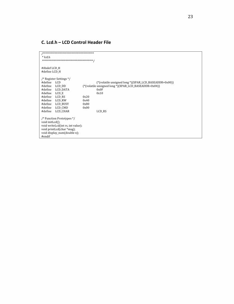
C.Lcd.h–LCDControlHeaderFile
/****************************************lcd.h***************************************/#ifndefLCD_H#defineLCD_H/*RegisterSettings*/#define LCD (*(volatileunsignedlong*)(XPAR_LCD_BASEADDR+0x00))#define LCD_DD (*(volatileunsignedlong*)(XPAR_LCD_BASEADDR+0x04))#define LCD_DATA 0x0F#define LCD_E 0x10#define LCD_RS 0x20#define LCD_RW 0x40#define LCD_BUSY 0x80#define LCD_CMD 0x00#define LCD_CHAR LCD_RS/*FunctionPrototypes*/voidinitLcd();voidwriteLcd(intrs,intvalue);voidprintLcd(char*msg);voiddisplay_num(doublen);#endif

24
D.LCD.c–LCDControlSourceCode
/******************************************lcd.c*****************************************/#include<xparameters.h>#include"lcd.h"intreadLcdStatus(){inti,r;/*SetLCDdatalinestoinputs*/LCD_DD=LCD_DATA; //Setdatalinestoinputs/*Firstreadcycle*/LCD=LCD_RW; LCD=LCD_RW|LCD_E;/*~125ns*/r=(LCD&LCD_DATA);/*~125ns(Ehighfor~250ns)*/for(i=0;i<5;++i)/*Wait~750ns*/LCD=LCD_RW;/*Secondreadcycle*/r<<=4;LCD=LCD_RW|LCD_E;/*~125ns*/r|=(LCD&LCD_DATA);/*~125ns(Ehighfor~250ns)*/for(i=0;i<5;++i)/*Wait~750ns*/LCD=LCD_RW;/*SetLCDbacktooutput*/LCD_DD=0; /*Sendbackstatusbyte*/returnr&0xFF;}voidsendLcd(intrs,intd){inti;/*Firstwritecycle*/LCD=rs; LCD=rs|LCD_E|d;/*~125ns*/LCD=rs|LCD_E|d;/*~125nstotalEhighfor~250ns*/LCD=rs|d; /*~125nsHoldtime*/for(i=0;i<5;++i)/*Wait~750ns*/LCD=rs;}voidreturnLcdHome(){/*SendcommandtoreturntheLCDcursortothehomeposition*/sendLcd(LCD_CMD,0x02);}voidwriteLcd(intrs,intvalue){inti,d;if(rs)

25
rs=LCD_RS;/*WaitfortheLCDtonotbebusy*/while(readLcdStatus()&LCD_BUSY);/*Senduppernibble*/sendLcd(rs,(value>>4)&LCD_DATA);/*Sendlowernibble*/sendLcd(rs,value&LCD_DATA);for(i=0;i<10;++i)LCD=0;/*Wait~1000ns*/} voidinitLcd(){inti;/*SetLCDdatalinestooutputs*/LCD_DD=0;for(i=0;i<20*5500;++i)LCD=0;/*~20msdelay*//*Setto8‐bitoperation*/sendLcd(LCD_CMD,0x03);for(i=0;i<500;++i)LCD=0;/*~91usdelay*//*Setto8‐bitoperation*/sendLcd(LCD_CMD,0x03);for(i=0;i<500;++i)LCD=0;/*~91usdelay*//*Setto8‐bitoperation*/sendLcd(LCD_CMD,0x03);for(i=0;i<500;++i)LCD=0;/*~91usdelay*//*Setto4‐bitoperation*/sendLcd(LCD_CMD,0x02);for(i=0;i<500;++i)LCD=0;/*~91usdelay*//*FunctionSet*/writeLcd(LCD_CMD,0x28);/*DisplayOn*/writeLcd(LCD_CMD,0x0C);/*ClearScreen*/writeLcd(LCD_CMD,0x01);/*SetEntryMode*/writeLcd(LCD_CMD,0x06);}voidprintLcd(char*msg){/*WriteoutthemessageacharacteratatimeuntilmsgpointstoNULL*/while(*msg)writeLcd(LCD_CHAR,*(msg++));}/*display_num:displaysthegivennumberupto*7digitsontheLCD*/voiddisplay_num(doublen)
26
{inti;/*Writeoutnegativesignifneeded*/if(n<0){writeLcd(LCD_CHAR,'‐');n*=‐1;}/*Converteachdigitforupto7digitsintoacharactertooutput*/unsignedcharmillions=((int)n/1000000)+48;unsignedcharhun_thousands=(((int)n%1000000)/100000)+48;unsignedcharten_thousands=(((int)n%100000)/10000)+48;unsignedcharthousands=(((int)n%10000)/1000)+48;unsignedcharhundreds=(((int)n%1000)/100)+48;unsignedchartens=(((int)n%100)/10)+48;unsignedcharones=((int)n%10)+48;unsignedchartenths;unsignedcharhundredths;/*Calculatethedecimalremainderbysubtractingtheotherplacesfromtheinputtednumber*/doubledecimal=n‐(millions‐48)‐(hun_thousands‐48)‐(ten_thousands‐48)‐(thousands‐48)‐(hundreds‐48)‐(ones‐48);/*Ifadecicalportionexists,calculatethetenthsandhundredthsvalues*/if(decimal>0){tenths=(int)(decimal*10)+48;hundredths=((int)(decimal*100)%10)+48;}/*Writeoutthemillionsdigitif>0*/if(n>=1000000)writeLcd(LCD_CHAR,millions);/*Writeoutthehundredthousandsdigitif>0*/if(n>=100000)writeLcd(LCD_CHAR,hun_thousands);/*Writeoutthetenthousandsdigitif>0*/if(n>=10000)writeLcd(LCD_CHAR,ten_thousands);/*Writeoutthethousandsdigitif>0*/if(n>=1000)writeLcd(LCD_CHAR,thousands);/*Writeoutthehundredsdigitif>0*/if(n>=100)writeLcd(LCD_CHAR,hundreds);/*Writeoutthetensdigit>0*/if(n>=10)writeLcd(LCD_CHAR,tens);/*Writeouttheonesdigit*/writeLcd(LCD_CHAR,ones);/*Checkifthere'sadecimalandthat

27
itismadeupofvalidnumbercharacters*/if(decimal>0&&tenths>47&&tenths<58){/*Writeoutthedecimaltothe hundredthsplace*/writeLcd(LCD_CHAR,'.');writeLcd(LCD_CHAR,tenths);writeLcd(LCD_CHAR,hundredths);}}
28
E.Timer.h–TimerControlHeaderFile
/**********************************timer.h*********************************/#ifndefTIMER_H#defineTIMER_H#define TCSR0 (*(volatileunsignedlong*)(XPAR_TIMER_BASEADDR+0x00))#define TLR0 (*(volatileunsignedlong*)(XPAR_TIMER_BASEADDR+0x04))#define TCR0 (*(volatileunsignedlong*)(XPAR_TIMER_BASEADDR+0x08))#define TCSR1 (*(volatileunsignedlong*)(XPAR_TIMER_BASEADDR+0x10))#define TLR1 (*(volatileunsignedlong*)(XPAR_TIMER_BASEADDR+0x14))#define TCR1 (*(volatileunsignedlong*)(XPAR_TIMER_BASEADDR+0x18))voidtimerISR(void);voidinitTimer(unsignedintcount,intset_interrupt);#endif
F.Timer.c–TimerControlSourceCode
/********************************timer.c*******************************/#include<xparameters.h>#include"timer.h"//#include"intc.h"//#include"leds.h"//#include"mux.h"voidinitTimer(unsignedintcount,intset_interrupt){ TLR0=count; //SetloadRegister TCSR0=0x072; //Turnontimerwithloadbit TCSR0=0x0D2; //Clearloadbit //if(set_interrupt) // SIE=XPAR_TIMER_INTERRUPT_MASK; //EnableInterruptinIntc}voidtimerISR(void){ //LEDS=nextSensor(); TCSR0=TCSR0;}

29
G.Leds.h–LEDControlHeaderFile
/******************************leds.h*****************************/#ifndefLEDS_H#defineLEDS_H#define LEDS (*(volatileunsignedlong*)(XPAR_LEDS_BASEADDR+0x00))#define LEDS_DD (*(volatileunsignedlong*)(XPAR_LEDS_BASEADDR+0x04))#define initLeds(){LEDS_DD=0x00;}#endif
H.main.c–SampleControlAlgorithmSourceCode
/**************************************FrankScarfo*CalPolySuPERProject*AnalogMUXcontrolsampleproject*File:main.c*************************************/#include<xio.h>#include<xparameters.h>#include"spi.h"#include"lcd.h"//#include"intc.h"#include"timer.h"#include"leds.h"#include"mux.h"#defineclock50000000#definefrequency20#defineclk_load(clock/(frequency*100))intdutycycle;longticks;longrecalc;doubleinput[64];longdataStart;voidmainISR()__attribute__((interrupt_handler));voidrecalcOutputs(){ inti; for(i=dataStart;i<dataStart+32;i++){ if(input[i]>1.8) dutycycle+=1; elseif(input[i]<1.5) dutycycle‐=1; }}

30
voidmainISR(){ /*AdjustPWMSignal*/ if(ticks<=(clk_load*dutycycle/10000)) LEDS|=0x80; elseLEDS&=0x0F; if(ticks>=clk_load/100) ticks=‐1; if(recalc>=frequency*100){ recalcOutputs(); recalc=0; dataStart=(dataStart+32)%64; } ticks++; recalc++; timerISR();//ResetTimer}intmain(){ inti,j,sel; unsignedintadc[2]={0x00,0x00}; doublein; /*InitializeAddDevices*/ initSPI(); clearSPI(); initLcd(); initLeds(); initMUX(); initTimer(clk_load,1); for(i=0;i<64;i++){ input[i]=1.7; } /*Initializeallvariables*/ ticks=0; recalc=0; dutycycle=50; dataStart=0; /*TurnOnInterrupts*/ microblaze_enable_interrupts(); for(;;) { /*Changeselectlinestonextinput*/ sel=nextSensor(); LEDS=sel; /*SetAmplifierValues*/ SPICR=0x08E; sendAmp(x2,x5);

31
SPICR=0x086; readADC(adc); SPICR=0x08E; sendAmp(x2,x5); SPICR=0x086; readADC(adc); SPICR=0x08E; sendAmp(x2,x5); SPICR=0x086; readADC(adc); /*GetADC1Value,Storeintoarray,andprinttoLCD*/ writeLcd(LCD_CMD,0x01); printLcd("S"); display_num(2.0*sel); printLcd(":"); in=getAdcVoltage(twosComplement(adc[0],14),0x2); input[2*sel+dataStart]=in; display_num(in); printLcd("v("); display_num(twosComplement(adc[0],14)); printLcd(")"); /*GetADC2Value,Storeintoarray,andprinttoLCD*/ writeLcd(LCD_CMD,0xC0); printLcd("S"); display_num(2.0*sel+1); printLcd(":"); printLcd(":"); in=getAdcVoltage(twosComplement(adc[1],14),0x2); input[2*sel+1+dataStart]=in; display_num(in); printLcd("v("); display_num(twosComplement(adc[1],14)); printLcd(")"); /*Delay‐Uncommentfordemopurposes*/ //for(j=0;j<1000000000;j++); }return0;}

32
I.spi.h–SPIControlHeaderFile
/********************************************spi.h*******************************************/#ifndefSPI_H#defineSPI_H/*Amplifiergainsettings(allvaluesarenegative!)*/#definex1 0x01#definex2 0x02#definex5 0x03#definex10 0x04#definex20 0x05#definex50 0x06#definex100 0x07/*Registersettings*///#defineFLASH_ADC_SEL_DD(*(volatileunsignedlong*)(XPAR_FLASH_ADC_SEL_BASEADDR+0x04))//#defineFLASH_ADC_SEL (*(volatileunsignedlong*)(XPAR_FLASH_ADC_SEL_BASEADDR+0x00))#defineAD_CONV_DD (*(volatileunsignedlong*)(XPAR_AD_CONV_BASEADDR+0x04))#defineAD_CONV (*(volatileunsignedlong*)(XPAR_AD_CONV_BASEADDR+0x00))#define SPICR (*(volatileunsignedlong*)(XPAR_SPI_BASEADDR+0x60))#define SPISR (*(volatileunsignedlong*)(XPAR_SPI_BASEADDR+0x64))#define SPIDTR (*(volatileunsignedlong*)(XPAR_SPI_BASEADDR+0x68))#define SPIDRR (*(volatileunsignedlong*)(XPAR_SPI_BASEADDR+0x6C))#define SPISSR (*(volatileunsignedlong*)(XPAR_SPI_BASEADDR+0x70))#define SPIGIE (*(volatileunsignedlong*)(XPAR_SPI_BASEADDR+0x1C))#define SPIISR (*(volatileunsignedlong*)(XPAR_SPI_BASEADDR+0x20))#define SPIIER (*(volatileunsignedlong*)(XPAR_SPI_BASEADDR+0x28))#define SPIRXF (*(volatileunsignedlong*)(XPAR_SPI_BASEADDR+0x78))/*Definedconstantsandmacros*/#define SPI_DAC 0x01#define SPI_AMP 0x02#define SPI_ADC 0x04#defineDAC_A0x00#defineDAC_B0x01#defineDAC_C0x02#defineDAC_D0x03#defineDAC_ALL0x0F#define sendDAC(n,val) writeSPI(SPI_DAC,0x00300000|(((n)&0x0F)<<16)|(((val)&0x0FFF)<<4),4)#define sendAmp(a,b) writeSPI(SPI_AMP,(((b)&0x07)<<4)|((a)&0x07),1)/*Functionprototypes*/voidinitSPI(void);voidclearSPI(void);intreadSPI(unsignedintnumBytes);voidwriteSPI(unsignedintdevice,unsignedintvalue,unsignedintnumBytes);voidreadADC(unsignedintadc[]);doublegetAdcVoltage(doubleadc_val,intgain);#endif

33
J.spi.c‐SPIControlSourceCode
/***********************************spi.c**********************************/#include<xparameters.h>#include<stdio.h>#include<stdlib.h>#include<string.h>#include"spi.h"//#include"intc.h"#include"lcd.h"staticunsignedintdeviceMask;inttwosComplement(unsignedintnum,intn){intnum_2s=0;inti;/*Functiononlyworksupto32bits.Return0ifnis>32*/if(n>32)return0;/*IftheMSBofthenumberisaonethenperformtwo'scomplementandnegatevalue*/elseif(num&(0x1<<(n‐1))){/*Takethecomplementofthenumber andadd1togetthetwo'scomplement value*/num_2s=~num+1;/*Zeroouttheupperbitsfromthe nthtothe32ndbit*/for(i=n;i<32;i++) num_2s&=~(0x1<<i);/*IftheMSBofthenumberisaone thennegatethetwo'scomplement value*/if(num&(0x1<<(n‐1))) num_2s*=‐1;}/*Positivenumber,whichisthesameasthetwo'scomplementequivalent*/elsenum_2s=num;returnnum_2s;}voidinitSPI(void){/*Setallsalveselectlineshigh*/SPISSR=~0;/*SetupSPIcontrolregister*/SPICR=0x086;

34
/*EnableSPIinterrupts*/SPIGIE=~0;/*Setupdevicemask,whichisthestatuswhenalltheSSlinesarehigh*/deviceMask=SPISSR;/*EnabletheinterruptinIntc*//*SIE=XPAR_OPB_SPI_0_IP2INTC_IRPT_MASK;*/}voidclearSPI(void){/*Waitforthelasttransactiontofinish*/while(SPISSR!=deviceMask);/*Setthe"TxFIFOReset"and"RxFIFOReset"Bits*/SPICR|=0x60;/*Clearthe"TxFIFOReset"and"RxFIFOReset"Bits*/SPICR&=~0x60;}voidreadADC(unsignedintadc[]){unsignedintvalue=0x00;/*ChangetheSPIcontrolregisterclockphase(CPHA)bitto'1'tochangethephasefortheADC*/SPICR=0x08E;/*ManuallytriggertheAD_CONVsignaltobeginreadingindatatotheADC*/AD_CONV_DD=0x0;AD_CONV=0x0;/*Waitforthelasttransactiontofinish.Allowsdatatobeconverted.*/while(SPISSR!=deviceMask); /*ManuallytriggertheAD_CONVsignalagaintobeginoutputofconverteddata*/AD_CONV=0x1;AD_CONV=0x0;/*ReadinvaluesfromtheADC,seperatethetwoADCAandBvaluesandstorethemintoanarray*/value=readSPI(4);adc[0]=((value>>16)&0x00003FFF);adc[1]=((value)&0x00003FFF);/*ResettheclockphasefortheSPIbusincaseanotherdeviceisbeingused,suchastheDAC*/SPICR=0x086;}intreadSPI(unsignedintnumBytes){intvalue=0;/*Forcethemaximumsendwidthtobe

35
fourbytes*/if(numBytes>4)numBytes=4;/*Waitforthelasttransactiontofinish*/while(SPISSR!=deviceMask);/*ReadineachbytefromtheRxFIFO*/for(;numBytes;‐‐numBytes) /*AppendthecurrentbytetotheLSBofthevalue*/value=(value<<8)|(SPIDRR&0x0FF);/*ReturnthefinalvaluereadinfromtheSPI*/returnvalue;}voidwriteSPI(unsignedintdevice,unsignedintvalue,unsignedintnumBytes){inti;/*Forcethemaximumsendwidthtobefourbytes*/if(numBytes>4)numBytes=4;/*Waitforthelasttransactiontofinish*/while(SPISSR!=deviceMask);/*LowertheSSlineforthespecifieddevice*/SPISSR&=~device;/*Specialcaseforwritingtotheamplifiers*/if(device==SPI_AMP){/*SendthesamebytetotheTxFIFOfourtimes toensuretheampsgetthenewsettings*/for(i=0;i<4;i++) SPIDTR=value;}/*Othercases*/else{/*PutthebytesofthedataintotheTxFIFO MSBfirst*/for(;numBytes;‐‐numBytes) { SPIDTR=(value>>((numBytes‐1)*8))&0xFF; }}/*WaitfordataintheTxFIFOtobetransmittedbypollingthestatusbit*/for(;;){if(SPISR&0x04) break;}/*RaisetheSSlineswhenfinished*/SPISSR=~0;}

36
doublegetAdcVoltage(doubleadc_val,intgain){doublevin;/*BasedontheUser'sGuideontheADC(p.76)*/doubledivisor=8192.0;/*SetthedivisorforcalculatingtheADCvoltagebasedonthegivengainsetting*/switch(gain){case0x1:divisor*=‐1.0;break;case0x2:divisor*=‐2.0;break;case0x3:divisor*=‐5.0;break;case0x4:divisor*=‐10.0;break;case0x5:divisor*=‐20.0;break;case0x6:divisor*=‐50.0;break;case0x7:divisor*=‐100.0;break;default:break;}/*CalculateADCinputvoltagebasedontheformulaintheUser'sGuide(p.76)*/vin=((adc_val/divisor)*1.25)+1.65;/*Sendinputvoltagevalueback*/returnvin;}

37
K.EmbeddedSystemBlockDiagram

38
L.AnalysisofSeniorProjectDesign
SummaryofFunctionalRequirements
ThisprojectimplementsananalogmultiplexertointerfaceaSpartan3eFPGAboardtotheCalPolySustainablePowerforElectricalResources(SuPER)project.Itincludessoftwaretocontrolthemultiplexeraswellasasamplecontrolalgorithmtodemonstratethecapabilitiesofthesystem.
PrimaryConstraints
TheSuPERproject’ssuccessisbasedontwomainconstraints,lowcostsandefficientuseofpower.Myprojectaidsingreatlyimprovingbothofthesecrucialareas.
Economic
WhilemyprojectcostfairlylittletoimplementitwillhaveaprofoundeffectontheunderdevelopedregionsaspartoftheSuPERproject.Byprovidingthesepeoplewithpowertoperformeverydaytasks,weenablethemtospendlesstimeongatheringtheirbasicneeds,allowingthemtoparticipateinmoreusefuleconomicactivity.
Commercial
Currently,theSuPERprojectisseveralyearsawayfrombeingviableforcommercialmarkets.Therestillneedstobeextensivetestingandimprovementstovarioussystemsbeforethiscanbefullyconsidered.
Environmental
TheSuPERprojectwillprovideextensiveimprovementsinthepushforrenewableenergy.Sustainablepowersuchassolarlowersthedemandforharmfulresourcessuchasoil.
Sustainability
Withsustainabilityasoneoftheprojectscoregoals,itwillprovideoneofthemostefficientsourcesofcleanenergy.Oursystemwillbeabletoprovidepowerforseveraldecadespoweredonlybysolarenergy.
HealthandSafety
Thisprojectwillonlyopenupmoreopportunitiesforpeopleinunderdevelopedareastolivehealthiersaferlives.Peoplewillbeabletousethe

39
powerprovidedtothesystemtorunwaterpumps,cooktheirfood,andassistinprovidingotherbasicneeds.
Development
DevelopmentforthisprojectwasalmostentirelydonewiththeXilinxEmbeddedDevelopmentKit(EDK).


