Implementation and Planning Best Practices for EMC VPLEX ... · 8 Configurations Implementation and...
37
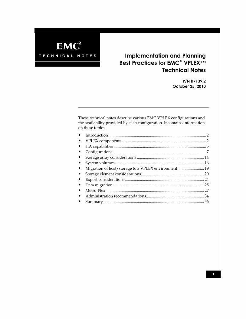
1 Implementation and Planning Best Practices for EMC ® VPLEX™ Technical Notes P/N h7139.2 October 25, 2010 These technical notes describe various EMC VPLEX configurations and the availability provided by each configuration. It contains information on these topics: Introduction ................................................................................................ 2 VPLEX components ................................................................................... 2 HA capabilities ........................................................................................... 5 Configurations ............................................................................................ 7 Storage array considerations .................................................................. 14 System volumes........................................................................................ 16 Migration of host/storage to a VPLEX environment .......................... 19 Storage element considerations.............................................................. 20 Export considerations .............................................................................. 24 Data migration.......................................................................................... 25 Metro-Plex ................................................................................................. 27 Administration recommendations......................................................... 34 Summary ................................................................................................... 36
Transcript of Implementation and Planning Best Practices for EMC VPLEX ... · 8 Configurations Implementation and...
1
Implementation and Planning
Best Practices for EMC® VPLEX™
Technical Notes
P/N h7139.2
October 25, 2010
These technical notes describe various EMC VPLEX configurations and the availability provided by each configuration. It contains information on these topics:
Introduction ................................................................................................ 2
VPLEX components ................................................................................... 2 HA capabilities ........................................................................................... 5 Configurations ............................................................................................ 7
Storage array considerations .................................................................. 14 System volumes........................................................................................ 16 Migration of host/storage to a VPLEX environment .......................... 19 Storage element considerations.............................................................. 20 Export considerations .............................................................................. 24 Data migration .......................................................................................... 25
Metro-Plex ................................................................................................. 27 Administration recommendations......................................................... 34 Summary ................................................................................................... 36
2
Introduction
Implementation and Planning Best Practices for EMC VPLEX Technical Notes
Introduction
EMC® VPLEX™ is a storage network-based federation solution that
provides nondisruptive, heterogeneous data movement and volume management functionality. VPLEX is an appliance-based solution that connects to SAN Fibre Channel switches. The VPLEX architecture is designed as a highly available solution and as with all data management products, high availability (HA) is a major component in most deployment strategies.
VPLEX will be offered in three ―EMC VPLEX Storage Cluster‖ or cluster configurations: small (VS1-02), medium (VS1-04), and large (VS1-08). Each VPLEX Cluster can function as a standalone single-site system, or can be linked to another VPLEX Cluster to function as a distributed, cache coherent system. VPLEX Clusters may be located in the same data center or in geographically distributed locations within Fibre Channel distances providing a 5 ms latency or less for synchronous cache write-through mode.
This document describes the VPLEX Cluster configurations available beginning with the hardware HA considerations, and then continuing through implementation best practices. VPLEX Cluster configurations are also reviewed. The review looks at each cluster configuration, its HA capabilities, and what is HA-protected and what is not part of the HA protection strategy.
Audience
These technical notes are for EMC field personnel and partners and customers who will be configuring, installing, and supporting VPLEX. An understanding of these technical notes requires an understanding of the following:
SAN technology and network design
Storage federation concepts
VPLEX concepts and components
The next section presents a brief review of VPLEX components.
VPLEX components
A VPLEX Cluster consists of the following hardware components:
VPLEX Engines
Directors
3
VPLEX components
Implementation and Planning Best Practices for EMC VPLEX Technical Notes
I/O modules
Standby Power Supplies (SPS)
Management server
Fibre Channel switches for internal director communications in the VS1-04 and VS1-08 clusters
VPLEX Engine
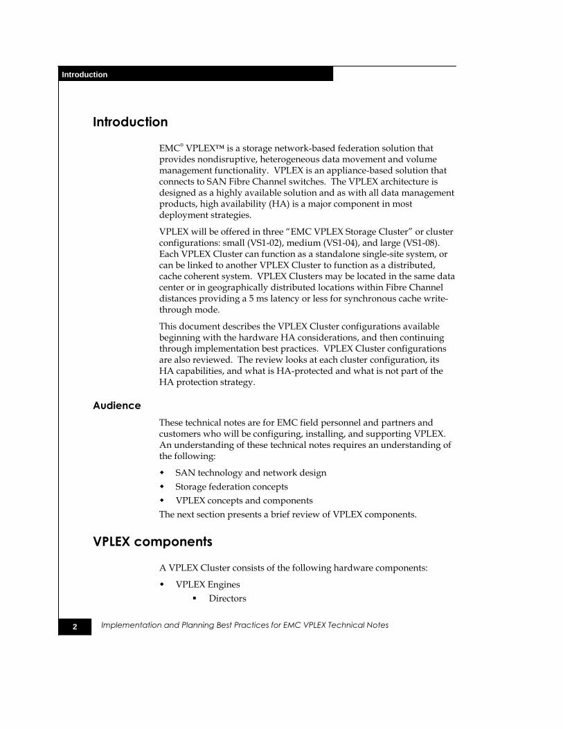
The following figures show the front and rear views of the VPLEX Engine and the three available cluster configurations.
Figure 1 Front and rear view of the VPLEX Engine
4
VPLEX components
Implementation and Planning Best Practices for EMC VPLEX Technical Notes
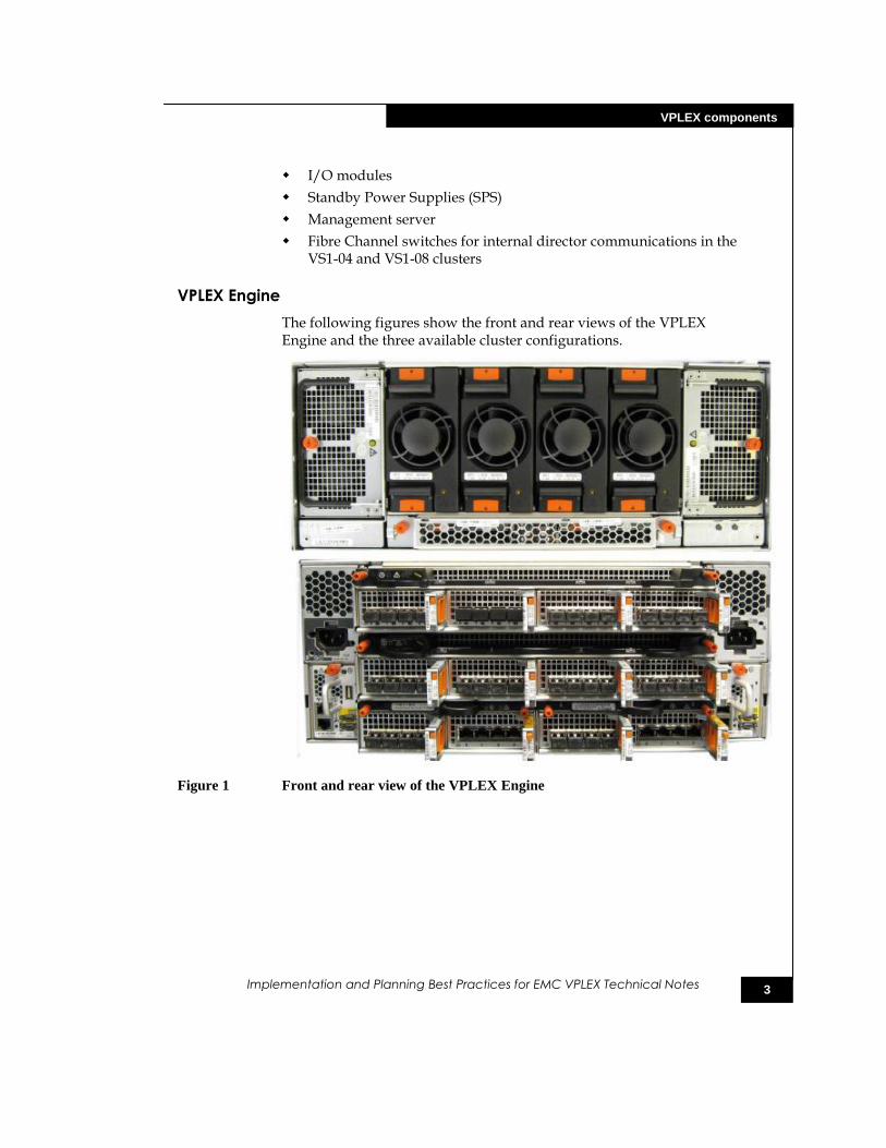
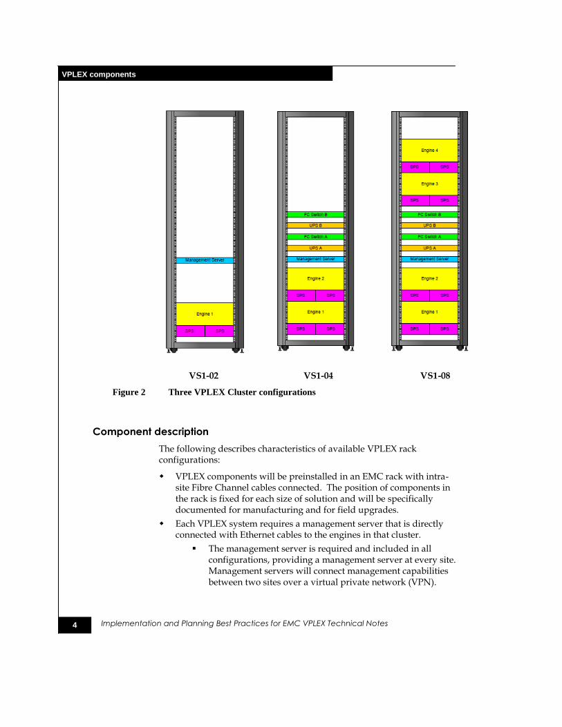
VS1-02 VS1-04 VS1-08
Figure 2 Three VPLEX Cluster configurations
Component description
The following describes characteristics of available VPLEX rack configurations:
VPLEX components will be preinstalled in an EMC rack with intra-site Fibre Channel cables connected. The position of components in the rack is fixed for each size of solution and will be specifically documented for manufacturing and for field upgrades.
Each VPLEX system requires a management server that is directly connected with Ethernet cables to the engines in that cluster.
The management server is required and included in all configurations, providing a management server at every site. Management servers will connect management capabilities between two sites over a virtual private network (VPN).
5
HA capabilities
Implementation and Planning Best Practices for EMC VPLEX Technical Notes
The management server is necessary for making configuration changes and providing access for call home features but is not required for data flow. The VPLEX directors handle all I/O traffic including read/write, SCSI commands, and error handling.
Three different VPLEX rack configurations are offered. To simplify the installation, servicing, and support of the VPLEX product, there is one standard VPLEX Engine configuration. All VPLEX solutions are based on the standard engine.
One VPLEX Engine houses two independent directors. Each director has four I/O modules, physically mounted in the director. Each director manages two additional I/O modules in the I/O annex. The I/O modules in the I/O annex are used for intra-director communications via an internal FC LAN and cluster-to-cluster communications via a FC MAN. There is also an I/O module for each director in the I/O annex that consists of four gigabit Ethernet ports that will not be utilized in the initial release of the product.
The four FC I/O modules mounted in the director have four 8 Gb/s FC ports to facilitate connectivity to the SAN. The first two I/O modules are configured as front-end (target ports) and the second two I/O modules are configured as back-end (initiator ports). This allows for connectivity to an A/B fabric design, on a per-director basis, without compromising data availability in the event of a module failure.
VPLEX configuration data is stored on external metadata devices provided from EMC arrays in the fabric. The metadata is mirrored across two different devices provisioned from two different arrays for HA purposes. Each director in the cluster must have access to both metadata devices. For EMC VPLEX Metro-Plex configurations, each cluster will have its own independent pair of metadata devices.
Each director contains 32 GB of cache and has its own dedicated SSD drive for booting.
HA capabilities
This section lists the HA capabilities provided by VPLEX.
HA provided with all VPLEX configurations
All VPLEX configurations provide the following HA capabilities. Any deviation from these provided capabilities will result in either a less-than-HA installation or will not be allowed through the qualifier.
Engines have the following HA capabilities:
6
HA capabilities
Implementation and Planning Best Practices for EMC VPLEX Technical Notes
Two directors that each contain:
o A CPU module.
o A local vault module, which provides an interface for HBA connections.
o Four Fibre Channel I/O modules. Each module provides four Fibre Channel ports, two of which are configured as front-end fiber-optic links (8 Gb/s, 4 Gb/s, or 2 Gb/s) and two that are configured as back-end fiber-optic links (8 Gb/s, 4 Gb/s, or 2 Gb/s). (Each port is independent of the others.)
Two I/O annexes (one for each director) that each provide additional I/O ports for a data path and communications between directors. Each I/O annex contains:
o One Fibre Channel I/O module (already described).
o One gigabit Ethernet I/O module, which provides four 1.26 Gb/s Ethernet ports.
Currently not used but present for future enhancements
Two management modules provide monitoring functions and contain interfaces for remote management of a VPLEX Engine. Either management module can be used to monitor and control the entire chassis.
Two Flash drives, one for each director, contain a 40 GB drive, which can be used to boot the CPU module.
Each director has 32 GB of memory. Single-site VPLEX systems and Metro-Plex systems use synchronous write through mode and will never contain dirty data that has not been committed to storage. Any power outages that may occur will not introduce data loss in these configurations.
Two power supplies are connected to two independent power sources through two SPS units.
Four cooling modules.
An SPS for each engine provides backup power that allows write caching and prevents data loss in case of a power failure.
Fibre Channel switches (two are provided, for high availability) provide intra-director connectivity in the VS1-04 and VS1-08 clusters. This component is required only if the system contains more than two directors. This component is configured for internal director communications within the cluster and is not connected to the customer SAN.
For the management server, in medium and large configurations (VS1-04 and VS1-08), the power feed is connected to UPS-A. This allows the management server to survive a single-zone power

7
Configurations
Implementation and Planning Best Practices for EMC VPLEX Technical Notes
outage and to prevent loss of manageability during a brief power outage.
What is not HA-protected
All VPLEX configurations are subject to the following potential single-points-of-failure issues:
The VPLEX cabinet contains two Power Distribution Panels (PDPs), each of which should be connected to a separate power supply.
Running both PDPs off the same power supply introduces a single point of failure. If external AC power is lost, the VPLEX instance becomes unavailable. Battery backup to the engines and internal FC switches preserves the metadata integrity. If power to the cabinet is not returned in 90 seconds, the directors are shut down. Note that the SPSs and Fibre Channel switches all have dual power capability that provides connection to independent power supplies.
The VPLEX management server in a small configuration VS1-02 is not connected to a UPS as this configuration does not ship with Fibre Channel switches or UPSs.
Additionally, VPLEX is only as highly available as the SAN it is connected to. Best practice recommendations are to have a dual fabric SAN. All hosts and storage arrays should be connected to both fabrics. Any single point of failure in the environment impacts the availability of VPLEX.
Configurations
This section describes the HA characteristics of single- and multiple-engine cluster configurations that are supported today. These characteristics apply to standalone clusters, therefore introducing another cluster and creating a Metro-Plex configuration increases availability.
Single VPLEX Engine
This configuration, shown in Figure 3, is the smallest VPLEX model that incorporates the HA capability of dual VPLEX directors. This configuration could be deployed in an infrastructure that manages data with HA requirements but does not have protection requirements greater than dual directors and dual data paths. This configuration provides the ability to perform a Non-Disruptive Upgrade (NDU) while maintaining data access for the hosts. Both directors reside in a single engine so some risk is assumed.
8
Configurations
Implementation and Planning Best Practices for EMC VPLEX Technical Notes
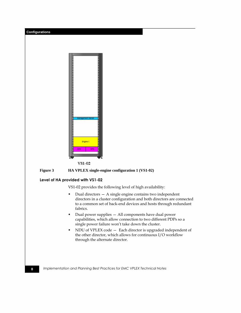
Figure 3 HA VPLEX single-engine configuration 1 (VS1-02)
Level of HA provided with VS1-02
VS1-02 provides the following level of high availability:
Dual directors — A single engine contains two independent directors in a cluster configuration and both directors are connected to a common set of back-end devices and hosts through redundant fabrics.
Dual power supplies — All components have dual power capabilities, which allow connection to two different PDPs so a single power failure won’t take down the cluster.
NDU of VPLEX code — Each director is upgraded independent of the other director, which allows for continuous I/O workflow through the alternate director.

9
Configurations
Implementation and Planning Best Practices for EMC VPLEX Technical Notes
Multi-engine VPLEX configurations (VS1-04 and VS1-08)
These configurations are the medium and large VPLEX Clusters that incorporate HA-capable dual or quad VPLEX Engines with two directors per engine. These configurations could be deployed in an infrastructure that manages data with HA requirements but does not have the protection requirement of separating components into different failure domains. These configurations provide the ability to perform an NDU while maintaining data access for the hosts with the potential impact of only losing 50 percent path access during the NDU. Directors reside in two independent engines so even a failure of an engine will not reduce availability below 50 percent data path access.
Figure 4 HA VPLEX multiple-engine configurations (VS1-04, VS1-08)
10
Configurations
Implementation and Planning Best Practices for EMC VPLEX Technical Notes
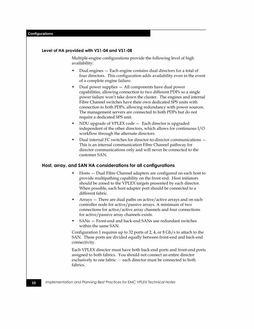
Level of HA provided with VS1-04 and VS1-08
Multiple-engine configurations provide the following level of high availability:
Dual engines — Each engine contains dual directors for a total of four directors. This configuration adds availability even in the event of a complete engine failure.
Dual power supplies — All components have dual power capabilities, allowing connection to two different PDPs so a single power failure won’t take down the cluster. The engines and internal Fibre Channel switches have their own dedicated SPS units with connection to both PDPs, allowing redundancy with power sources. The management servers are connected to both PDPs but do not require a dedicated SPS unit.
NDU upgrade of VPLEX code — Each director is upgraded independent of the other directors, which allows for continuous I/O workflow through the alternate directors.
Dual internal FC switches for director-to-director communications — This is an internal communication Fibre Channel pathway for director communications only and will never be connected to the customer SAN.
Host, array, and SAN HA considerations for all configurations
Hosts — Dual Fibre Channel adapters are configured on each host to provide multipathing capability on the front end. Host initiators should be zoned to the VPLEX targets presented by each director. When possible, each host adapter port should be connected to a different fabric.
Arrays — There are dual paths on active/active arrays and on each controller node for active/passive arrays. A minimum of two connections for active/active array channels and four connections for active/passive array channels exists.
SANs — Front-end and back-end SANs use redundant switches within the same SAN.
Configuration 1 requires up to 32 ports of 2, 4, or 8 Gb/s to attach to the SAN. These ports are divided equally between front-end and back-end connectivity.
Each VPLEX director must have both back-end ports and front-end ports assigned to both fabrics. You should not connect an entire director exclusively to one fabric — each director must be connected to both fabrics.
11
Configurations
Implementation and Planning Best Practices for EMC VPLEX Technical Notes
When configuring mirroring or migration across arrays, it is suggested that each array be accessed through different back-end director ports whenever possible.
Additional HA implementation considerations for Metro-Plex
A cluster can be combined with another cluster to form a Metro-Plex. This combination increases availability by allowing the hardware to exist in two geographically separate locations and eliminate any risk of having a single point of failure even with the single-engine cluster. The connectivity for host and storage covered in the next section apply to the clusters in both locations.
Connectivity and I/O paths
This section covers the hardware connectivity best practices for connecting to the SAN. These best practices are based on a dual-fabric SAN, which is considered a SAN best practice itself. Host connectivity as well as active and passive array connectivity will be discussed. The VPLEX hardware is designed with a standard preconfigured port arrangement that is not reconfigurable.
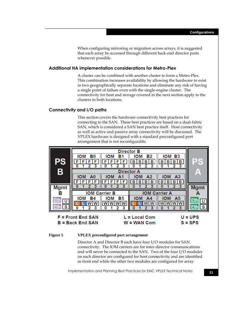
Figure 5 VPLEX preconfigured port arrangement
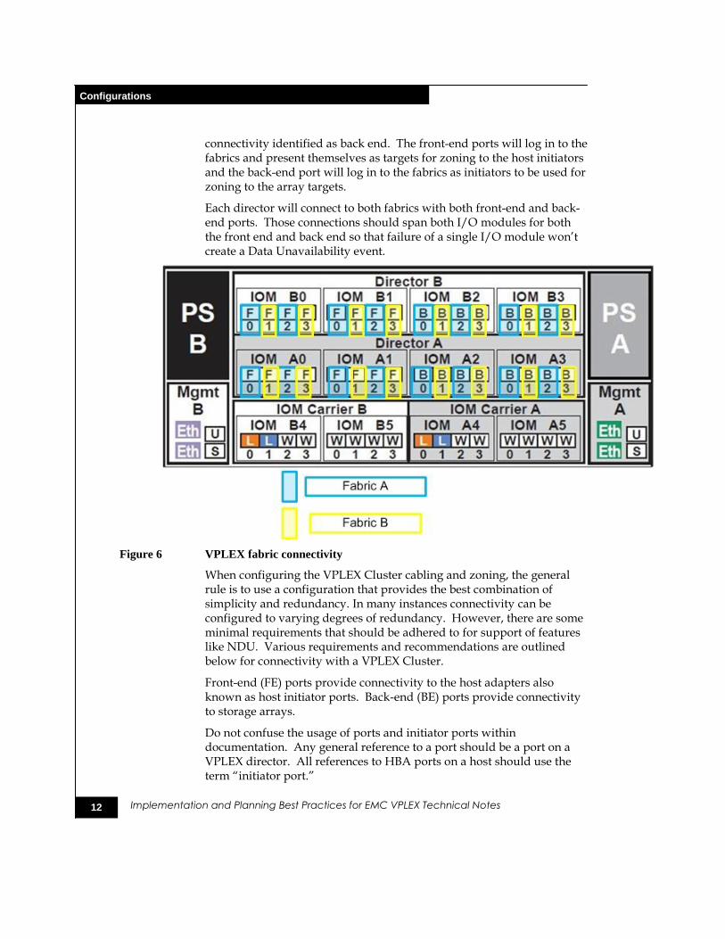
Director A and Director B each have four I/O modules for SAN connectivity. The IOM carriers are for inter-director communications and will never be connected to the SAN. Two of the four I/O modules on each director are configured for host connectivity and are identified as front end while the other two modules are configured for array
12
Configurations
Implementation and Planning Best Practices for EMC VPLEX Technical Notes
connectivity identified as back end. The front-end ports will log in to the fabrics and present themselves as targets for zoning to the host initiators and the back-end port will log in to the fabrics as initiators to be used for zoning to the array targets.
Each director will connect to both fabrics with both front-end and back-end ports. Those connections should span both I/O modules for both the front end and back end so that failure of a single I/O module won’t create a Data Unavailability event.
Figure 6 VPLEX fabric connectivity
When configuring the VPLEX Cluster cabling and zoning, the general rule is to use a configuration that provides the best combination of simplicity and redundancy. In many instances connectivity can be configured to varying degrees of redundancy. However, there are some minimal requirements that should be adhered to for support of features like NDU. Various requirements and recommendations are outlined below for connectivity with a VPLEX Cluster.
Front-end (FE) ports provide connectivity to the host adapters also known as host initiator ports. Back-end (BE) ports provide connectivity to storage arrays.
Do not confuse the usage of ports and initiator ports within documentation. Any general reference to a port should be a port on a VPLEX director. All references to HBA ports on a host should use the term ―initiator port.‖
13
Configurations
Implementation and Planning Best Practices for EMC VPLEX Technical Notes
The ―Metro-Plex‖ section has a more specific discussion of cluster-to-cluster connectivity.
General information (applies to both FE and BE)
The following are recommended:
Each director should physically connect to a fabric for host (front-end) and back-end storage connectivity.
Redundant zone/paths to a director should not be to the same I/O module (applies to FE and BE).
Fabric zoning should consist of a set of zones, each with a single initiator and up to 16 targets.
Avoid incorrect FC port speed between the fabric and VPLEX.
Use redundant SAN fabrics.
If a director's FE or BE ports are not fully utilized, it is best to spread usage across available I/O modules for maximum hardware redundancy.
Back-end/storage array connectivity
Each director in a cluster must have an I/O path to every back-end storage array (required).
Each director will have redundant physical connections to the back-end storage fabrics (recommended).
Each director is required to have redundant paths to every back-end storage array. Otherwise this would create a single point of failure at the director level that could lead to rebuilds that continuously start/restart and never finish.
Each storage array should have redundant controllers, each with a minimum of two ports connected to the back-end storage fabric (recommended).
Front-end/host initiator port connectivity
The front-end fabric should have a minimum of two physical connections to each director (recommended).
Each host should have at least two paths to a cluster (recommended).
Each host should have at least one path to an A director and one path to a B director (required for NDU).
Each host should have redundant physical connections to the front-end fabric (recommended).
Each host should have fabric zoning that provides redundant access to each LUN from a minimum of two directors.
14
Storage array considerations
Implementation and Planning Best Practices for EMC VPLEX Technical Notes
More information is available in the ―Export considerations‖ section.
Additional recommendations
If more than one engine is available, spread I/O paths across engines as well as directors.
Complete physical connections to the VPLEX before commissioning/setup.
Use the same FE/BE ports on each director to avoid confusion, that is, B0-FC00 and A0-FC00.
Storage array considerations
Some arrays have architecture and implementation requirements that necessitate special consideration. When using an active-passive array, each director needs to have logical (zoning and masking) and physical connectivity to both the active and passive controllers. That way you will not lose access to storage volumes if an active controller should fail. Additionally, arrays like the CLARiiON® have limitations on the size of initiator or storage groups. It may be necessary to have multiple groups to accommodate provisioning storage to the VPLEX. Adhere to logical and physical connectivity guidelines discussed earlier.
The following diagram shows typical fabric connectivity to CLARiiON arrays.
15
Storage array considerations
Implementation and Planning Best Practices for EMC VPLEX Technical Notes
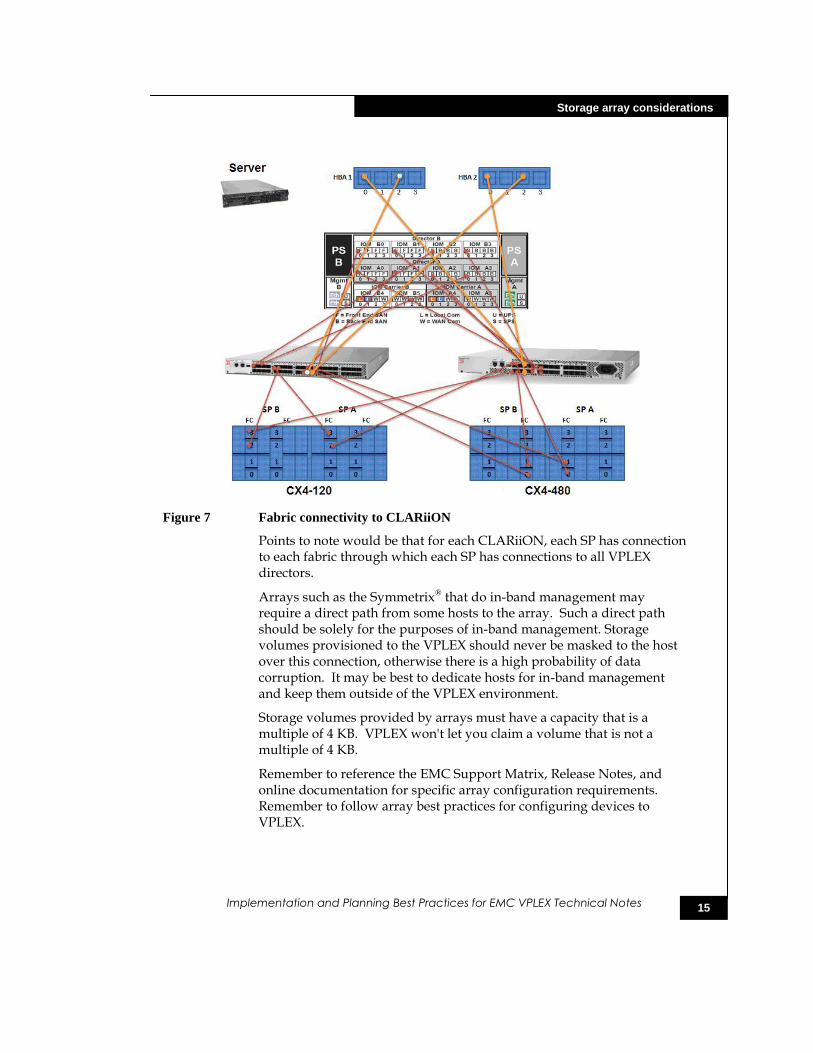
Figure 7 Fabric connectivity to CLARiiON
Points to note would be that for each CLARiiON, each SP has connection to each fabric through which each SP has connections to all VPLEX directors.
Arrays such as the Symmetrix® that do in-band management may require a direct path from some hosts to the array. Such a direct path should be solely for the purposes of in-band management. Storage volumes provisioned to the VPLEX should never be masked to the host over this connection, otherwise there is a high probability of data corruption. It may be best to dedicate hosts for in-band management and keep them outside of the VPLEX environment.
Storage volumes provided by arrays must have a capacity that is a multiple of 4 KB. VPLEX won't let you claim a volume that is not a multiple of 4 KB.
Remember to reference the EMC Support Matrix, Release Notes, and online documentation for specific array configuration requirements. Remember to follow array best practices for configuring devices to VPLEX.
16
System volumes
Implementation and Planning Best Practices for EMC VPLEX Technical Notes
System volumes
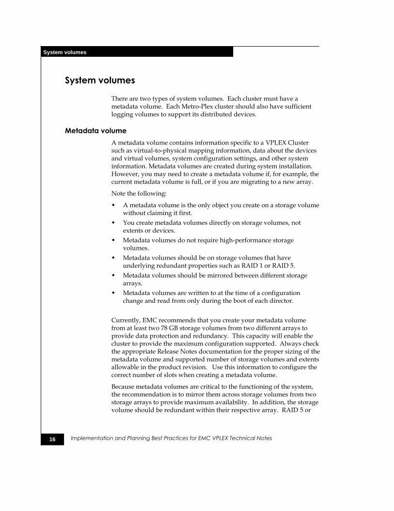
There are two types of system volumes. Each cluster must have a metadata volume. Each Metro-Plex cluster should also have sufficient logging volumes to support its distributed devices.
Metadata volume
A metadata volume contains information specific to a VPLEX Cluster such as virtual-to-physical mapping information, data about the devices and virtual volumes, system configuration settings, and other system information. Metadata volumes are created during system installation. However, you may need to create a metadata volume if, for example, the current metadata volume is full, or if you are migrating to a new array.
Note the following:
A metadata volume is the only object you create on a storage volume without claiming it first.
You create metadata volumes directly on storage volumes, not extents or devices.
Metadata volumes do not require high-performance storage volumes.
Metadata volumes should be on storage volumes that have underlying redundant properties such as RAID 1 or RAID 5.
Metadata volumes should be mirrored between different storage arrays.
Metadata volumes are written to at the time of a configuration change and read from only during the boot of each director.
Currently, EMC recommends that you create your metadata volume from at least two 78 GB storage volumes from two different arrays to provide data protection and redundancy. This capacity will enable the cluster to provide the maximum configuration supported. Always check the appropriate Release Notes documentation for the proper sizing of the metadata volume and supported number of storage volumes and extents allowable in the product revision. Use this information to configure the correct number of slots when creating a metadata volume.
Because metadata volumes are critical to the functioning of the system, the recommendation is to mirror them across storage volumes from two storage arrays to provide maximum availability. In addition, the storage volume should be redundant within their respective array. RAID 5 or
17
System volumes
Implementation and Planning Best Practices for EMC VPLEX Technical Notes
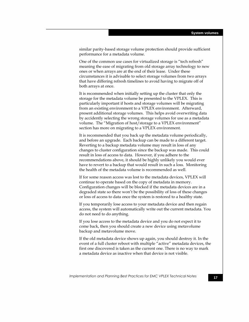
similar parity-based storage volume protection should provide sufficient performance for a metadata volume.
One of the common use cases for virtualized storage is ―tech refresh‖ meaning the ease of migrating from old storage array technology to new ones or when arrays are at the end of their lease. Under these circumstances it is advisable to select storage volumes from two arrays that have differing refresh timelines to avoid having to migrate off of both arrays at once.
It is recommended when initially setting up the cluster that only the storage for the metadata volume be presented to the VPLEX. This is particularly important if hosts and storage volumes will be migrating from an existing environment to a VPLEX environment. Afterward, present additional storage volumes. This helps avoid overwriting data by accidently selecting the wrong storage volumes for use as a metadata volume. The ―Migration of host/storage to a VPLEX environment‖ section has more on migrating to a VPLEX environment.
It is recommended that you back up the metadata volume periodically, and before an upgrade. Each backup can be made to a different target. Reverting to a backup metadata volume may result in loss of any changes to cluster configuration since the backup was made. This could result in loss of access to data. However, if you adhere to the recommendations above, it should be highly unlikely you would ever have to revert to a backup that would result in such a loss. Monitoring the health of the metadata volume is recommended as well.
If for some reason access was lost to the metadata devices, VPLEX will continue to operate based on the copy of metadata in memory. Configuration changes will be blocked if the metadata devices are in a degraded state so there won’t be the possibility of loss of these changes or loss of access to data once the system is restored to a healthy state.
If you temporarily lose access to your metadata device and then regain access, the system will automatically write out the current metadata. You do not need to do anything.
If you lose access to the metadata device and you do not expect it to come back, then you should create a new device using metavolume backup and metavolume move.
If the old metadata device shows up again, you should destroy it. In the event of a full cluster reboot with multiple ―active‖ metadata devices, the first one discovered is taken as the current one. There is no way to mark a metadata device as inactive when that device is not visible.
18
System volumes
Implementation and Planning Best Practices for EMC VPLEX Technical Notes
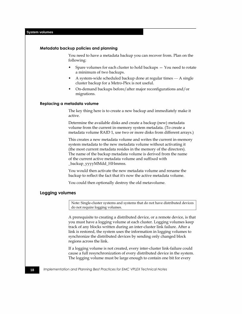
Metadata backup policies and planning
You need to have a metadata backup you can recover from. Plan on the following:
Spare volumes for each cluster to hold backups — You need to rotate a minimum of two backups.
A system-wide scheduled backup done at regular times — A single cluster backup for a Metro-Plex is not useful.
On-demand backups before/after major reconfigurations and/or migrations.
Replacing a metadata volume
The key thing here is to create a new backup and immediately make it active.
Determine the available disks and create a backup (new) metadata volume from the current in-memory system metadata. (To create a metadata volume RAID 1, use two or more disks from different arrays.)
This creates a new metadata volume and writes the current in-memory system metadata to the new metadata volume without activating it (the most current metadata resides in the memory of the directors). The name of the backup metadata volume is derived from the name of the current active metadata volume and suffixed with _backup_yyyyMMdd_HHmmss.
You would then activate the new metadata volume and rename the backup to reflect the fact that it's now the active metadata volume.
You could then optionally destroy the old metavolume.
Logging volumes
Note: Single-cluster systems and systems that do not have distributed devices do not require logging volumes.
A prerequisite to creating a distributed device, or a remote device, is that you must have a logging volume at each cluster. Logging volumes keep track of any blocks written during an inter-cluster link failure. After a link is restored, the system uses the information in logging volumes to synchronize the distributed devices by sending only changed block regions across the link.
If a logging volume is not created, every inter-cluster link-failure could cause a full resynchronization of every distributed device in the system. The logging volume must be large enough to contain one bit for every
19
Migration of host/storage to a VPLEX environment
Implementation and Planning Best Practices for EMC VPLEX Technical Notes
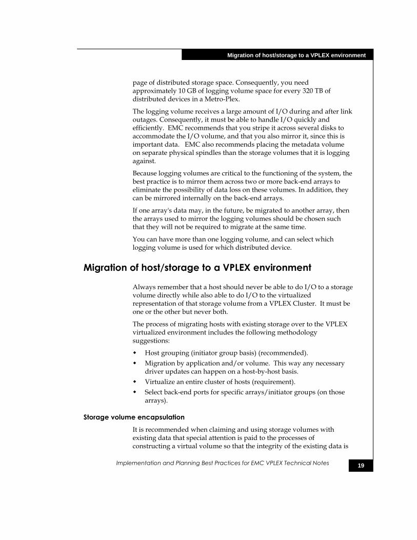
page of distributed storage space. Consequently, you need approximately 10 GB of logging volume space for every 320 TB of distributed devices in a Metro-Plex.
The logging volume receives a large amount of I/O during and after link outages. Consequently, it must be able to handle I/O quickly and efficiently. EMC recommends that you stripe it across several disks to accommodate the I/O volume, and that you also mirror it, since this is important data. EMC also recommends placing the metadata volume on separate physical spindles than the storage volumes that it is logging against.
Because logging volumes are critical to the functioning of the system, the best practice is to mirror them across two or more back-end arrays to eliminate the possibility of data loss on these volumes. In addition, they can be mirrored internally on the back-end arrays.
If one array's data may, in the future, be migrated to another array, then the arrays used to mirror the logging volumes should be chosen such that they will not be required to migrate at the same time.
You can have more than one logging volume, and can select which logging volume is used for which distributed device.
Migration of host/storage to a VPLEX environment
Always remember that a host should never be able to do I/O to a storage volume directly while also able to do I/O to the virtualized representation of that storage volume from a VPLEX Cluster. It must be one or the other but never both.
The process of migrating hosts with existing storage over to the VPLEX virtualized environment includes the following methodology suggestions:
Host grouping (initiator group basis) (recommended).
Migration by application and/or volume. This way any necessary driver updates can happen on a host-by-host basis.
Virtualize an entire cluster of hosts (requirement).
Select back-end ports for specific arrays/initiator groups (on those arrays).
Storage volume encapsulation
It is recommended when claiming and using storage volumes with existing data that special attention is paid to the processes of constructing a virtual volume so that the integrity of the existing data is
20
Storage element considerations
Implementation and Planning Best Practices for EMC VPLEX Technical Notes
maintained and available through the virtual volume.
You must create a single extent across the entire capacity of each storage volume.
You must protect the data when creating devices.
The recommendation is to use the application consistent attribute to protect data.
Use proper methods to create mirror local devices and distributed devices.
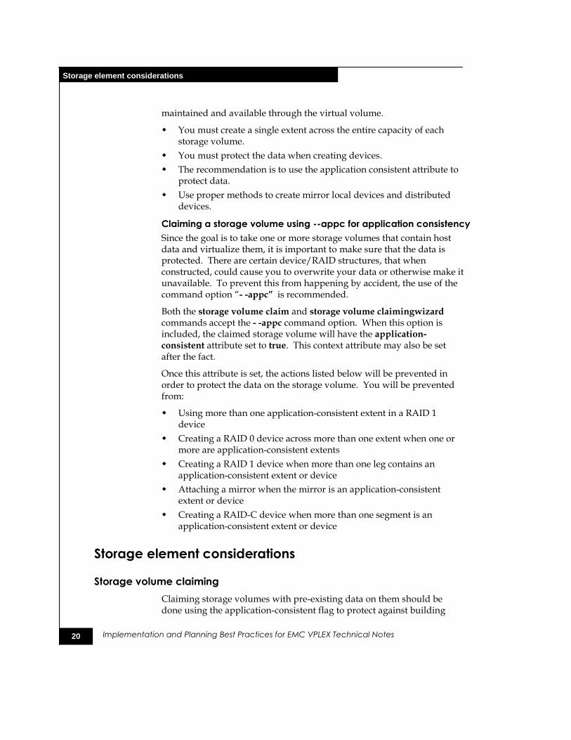
Claiming a storage volume using --appc for application consistency
Since the goal is to take one or more storage volumes that contain host data and virtualize them, it is important to make sure that the data is protected. There are certain device/RAID structures, that when constructed, could cause you to overwrite your data or otherwise make it unavailable. To prevent this from happening by accident, the use of the command option ―- -appc” is recommended.
Both the storage volume claim and storage volume claimingwizard commands accept the - -appc command option. When this option is included, the claimed storage volume will have the application-consistent attribute set to true. This context attribute may also be set after the fact.
Once this attribute is set, the actions listed below will be prevented in order to protect the data on the storage volume. You will be prevented from:
Using more than one application-consistent extent in a RAID 1 device
Creating a RAID 0 device across more than one extent when one or more are application-consistent extents
Creating a RAID 1 device when more than one leg contains an application-consistent extent or device
Attaching a mirror when the mirror is an application-consistent extent or device
Creating a RAID-C device when more than one segment is an application-consistent extent or device
Storage element considerations
Storage volume claiming
Claiming storage volumes with pre-existing data on them should be done using the application-consistent flag to protect against building

21
Storage element considerations
Implementation and Planning Best Practices for EMC VPLEX Technical Notes
VPLEX devices upon them in such a way as to make the data unavailable or corrupting it. This is part of the storage volume encapsulation process. The section ―Migration of host/storage to a VPLEX environment‖ has more information.
Remember that storage volumes must have a capacity that is a multiple of 4 KB. VPLEX won't let you claim a volume that is not a multiple of 4 KB.
Although it is possible to claim individual storage volumes, it is preferable to use the claiming wizard to claim dozens or hundreds of storage volumes in one operation. The claiming wizard will assign meaningful names to claimed storage volumes, including an array identifier and a device number or name. The array identifier included in the meaningful storage volume names will let you quickly identify storage volumes from a given array (useful, for example, when you want to migrate virtual volumes off a storage array you want to decommission). The device number or name in the meaningful storage volume name lets you correlate that VPLEX storage volume with a given LUN visible in the array's management interface. This will come in handy when you want to troubleshoot performance issues starting at the array.
The claiming wizard also provides a mechanism to include a storage tier identifier in the storage volume names, which can be used in capacity reports, as well as form the basis of a tiered block storage federation solution.
Some storage arrays such as EMC Symmetrix and HDS USP report the array serial number and device name in their responses to standard SCSI inquiries; the claiming wizard can claim their storage volumes without requiring any additional files. For other storage arrays, the storage administrator must use the array's command-line tools to generate a ―hints‖ file that declares the device names and their World Wide Names. This file is then input to the claiming wizard. In addition, you can also run the claiming wizard using the --dry-run option and use the output as a source to create a custom hints file. Also, note that the hints file can be used to selectively add more control over the claiming wizard behavior for arrays like the EMC Symmetrix and HDS USP.
Extent sizing
Extents should be sized to match the desired virtual volume's capacity. If the storage volume you want to use for an extent is larger than the desired virtual volume, create an extent the size of the desired virtual volume. Do not create smaller extents and then use devices to concatenate or stripe the extents.
22
Storage element considerations
Implementation and Planning Best Practices for EMC VPLEX Technical Notes
Creating smaller extents on the same storage volume and using devices to concatenate or stripe these extents may create spindle contention on the underlying storage volume and not provide any protection from storage volume failure. Creating smaller extents on different storage volumes and using devices to concatenate or stripe these extents will distribute the virtual volume's I/O over multiple storage volumes, which may be beneficial for throughout and responsiveness in some cases, but it also creates additional management complexity. You should only do this when you know the I/O pattern will benefit from this.
When disk capacities are smaller than desired volume capacities, best practice is to create a single slice per disk, and use RAID structures to concatenate or stripe these slices into a larger RAID.
1
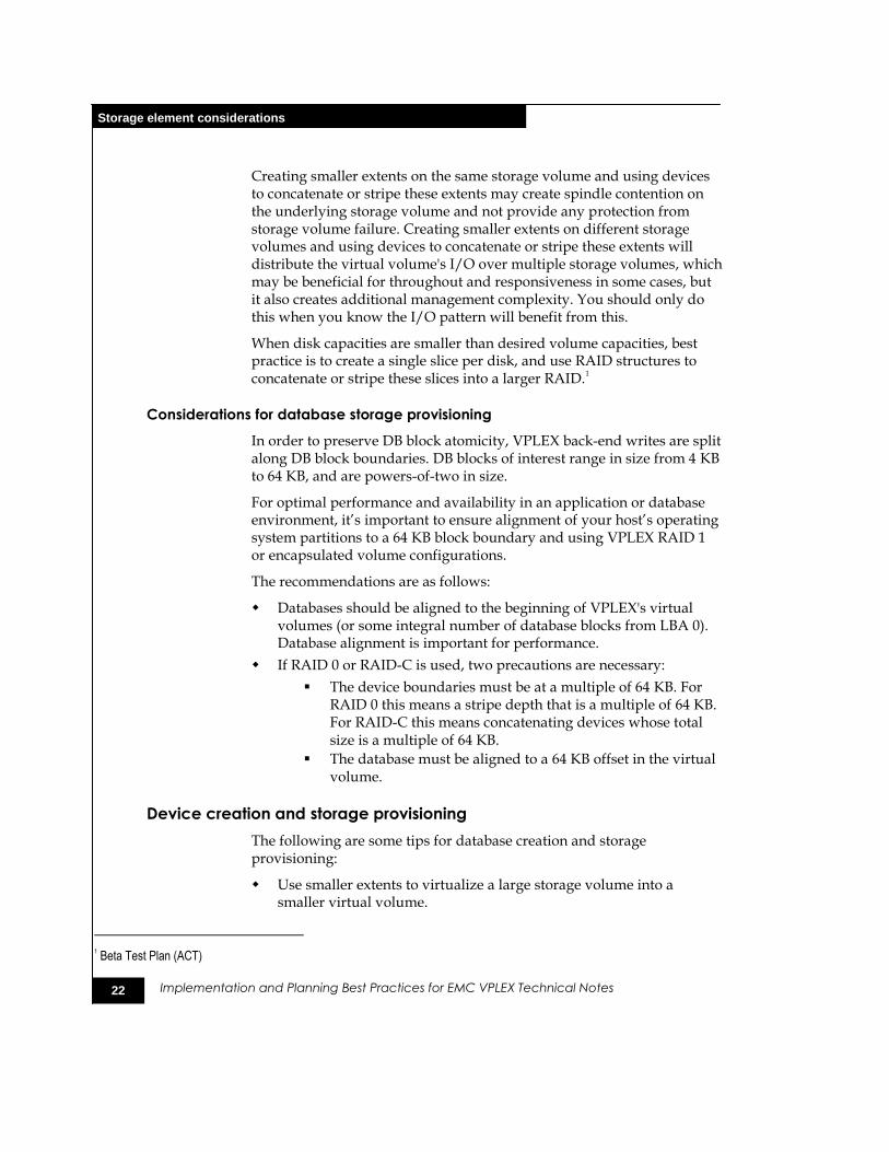
Considerations for database storage provisioning
In order to preserve DB block atomicity, VPLEX back-end writes are split along DB block boundaries. DB blocks of interest range in size from 4 KB to 64 KB, and are powers-of-two in size.
For optimal performance and availability in an application or database environment, it’s important to ensure alignment of your host’s operating system partitions to a 64 KB block boundary and using VPLEX RAID 1 or encapsulated volume configurations.
The recommendations are as follows:
Databases should be aligned to the beginning of VPLEX's virtual volumes (or some integral number of database blocks from LBA 0). Database alignment is important for performance.
If RAID 0 or RAID-C is used, two precautions are necessary:
The device boundaries must be at a multiple of 64 KB. For RAID 0 this means a stripe depth that is a multiple of 64 KB. For RAID-C this means concatenating devices whose total size is a multiple of 64 KB.
The database must be aligned to a 64 KB offset in the virtual volume.
Device creation and storage provisioning
The following are some tips for database creation and storage provisioning:
Use smaller extents to virtualize a large storage volume into a smaller virtual volume.
1 Beta Test Plan (ACT)
23
Storage element considerations
Implementation and Planning Best Practices for EMC VPLEX Technical Notes
Use device geometries consisting of either RAID 0 or RAID-C types to virtualize smaller extents into a larger virtual volume
Remember that you can create one to 128 extents on a single storage volume. The default is one extent comprised of the whole storage volume.
Avoid creating RAID 0 structures on storage volumes that are constructed from stripes in the storage array. This could create hot spots in the array.
Stacking of RAID 0s
When creating a device the underlying storage should be taken into account. If the underlying storage volume has RAID 0 or stripe properties from the storage array, the VPLEX administrator should use that storage in a device with RAID 1 or RAID-C properties (not RAID 0 properties). This is to avoid reverse mapping of RAID 0 or stripe, which could create hot spots on the spindles underneath it all.
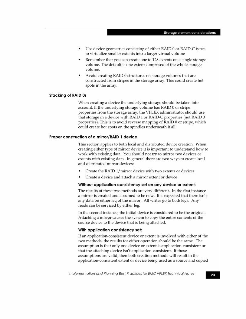
Proper construction of a mirror/RAID 1 device
This section applies to both local and distributed device creation. When creating either type of mirror device it is important to understand how to work with existing data. You should not try to mirror two devices or extents with existing data. In general there are two ways to create local and distributed mirror devices:
Create the RAID 1/mirror device with two extents or devices
Create a device and attach a mirror extent or device
Without application consistency set on any device or extent:
The results of these two methods are very different. In the first instance a mirror is created and assumed to be new. It is expected that there isn’t any data on either leg of the mirror. All writes go to both legs. Any reads can be serviced by either leg.
In the second instance, the initial device is considered to be the original. Attaching a mirror causes the system to copy the entire contents of the source device to the device that is being attached.
With application consistency set:
If an application-consistent device or extent is involved with either of the two methods, the results for either operation should be the same. The assumption is that only one device or extent is application-consistent or that the attaching device isn’t application-consistent. If those assumptions are valid, then both creation methods will result in the application-consistent extent or device being used as a source and copied
24
Export considerations
Implementation and Planning Best Practices for EMC VPLEX Technical Notes
to the other extent or device. If those assumptions are not valid, then the creation will fail because it violates the protection established by the application-consistency attribute.
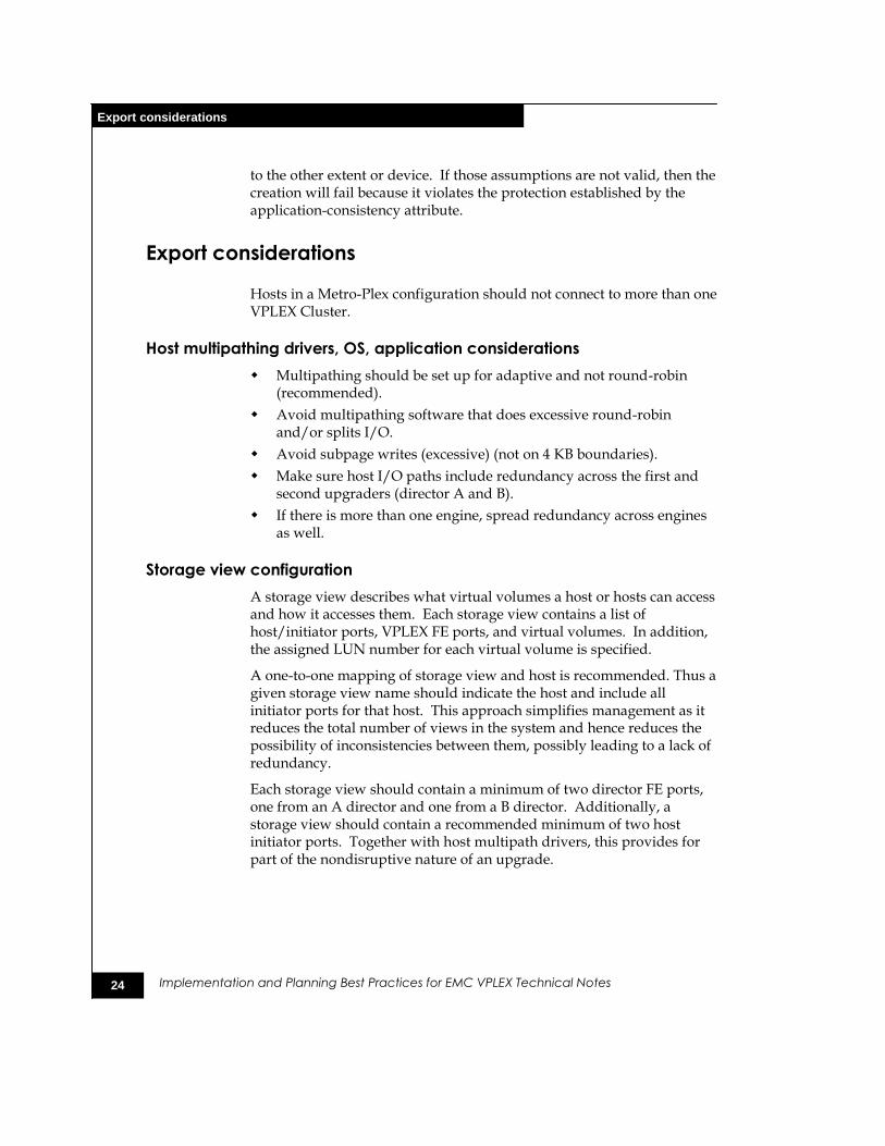
Export considerations
Hosts in a Metro-Plex configuration should not connect to more than one VPLEX Cluster.
Host multipathing drivers, OS, application considerations
Multipathing should be set up for adaptive and not round-robin (recommended).
Avoid multipathing software that does excessive round-robin and/or splits I/O.
Avoid subpage writes (excessive) (not on 4 KB boundaries).
Make sure host I/O paths include redundancy across the first and second upgraders (director A and B).
If there is more than one engine, spread redundancy across engines as well.
Storage view configuration
A storage view describes what virtual volumes a host or hosts can access and how it accesses them. Each storage view contains a list of host/initiator ports, VPLEX FE ports, and virtual volumes. In addition, the assigned LUN number for each virtual volume is specified.
A one-to-one mapping of storage view and host is recommended. Thus a given storage view name should indicate the host and include all initiator ports for that host. This approach simplifies management as it reduces the total number of views in the system and hence reduces the possibility of inconsistencies between them, possibly leading to a lack of redundancy.
Each storage view should contain a minimum of two director FE ports, one from an A director and one from a B director. Additionally, a storage view should contain a recommended minimum of two host initiator ports. Together with host multipath drivers, this provides for part of the nondisruptive nature of an upgrade.

25
Data migration
Implementation and Planning Best Practices for EMC VPLEX Technical Notes
Data migration
Extent migration
Extent migration is the process of nondisruptively moving an extent from one storage volume to another. An extent migration should be used when:
Relocating an extent from a ―hot‖ storage volume shared by other busy extents.
―Defragmenting‖ a storage volume to create contiguous free space.
Source and target arrays have a similar configuration, that is, the same number of storage volumes, identical capacities, and so on.
Device migration
Device migration is the process of nondisruptively moving a device from one set of extents to another. A device migration should be used when:
Migrating data between dissimilar arrays. For example, a storage administrator might need to slice or combine extents on a target array’s storage volumes to create devices that match the capacities of existing devices on the source array.
Relocating a ―hot‖ device from one type of storage to another.
Relocating a device from an array behind one VPLEX in a Metro-Plex cluster to an array behind a different VPLEX Cluster (a VPLEX exclusive).
Batch migration
A batch migration is a group of extent or device migrations that are executed as a single migration job. A batch migration should be used for:
Nondisruptive technology refreshes and lease rollovers
Nondisruptive cross Metro-Plex device migration, that is, moving data to an array at a different site (a VPLEX exclusive)
Migration jobs
A 2 MB transfer size will yield the best throughput while maintaining the best front-end performance in most environments. The best practice is to monitor the migration's effect on the host application and to adjust down the transfer size if it is too high. It’s very unlikely that the user will ever need or want to go higher than 2 MB.
Consider pausing migrations during the day and resuming them at night or during off-peak hours to reduce the potential performance impact.
26
Data migration
Implementation and Planning Best Practices for EMC VPLEX Technical Notes
Consider committing migration jobs shortly after they complete to avoid double writes to both the source and target RAIDs, which could potentially affect performance.
Performance notes
Migration and front-end performance will primarily depend on:
Back-end storage layout (physical disks, RAID type, number of connections)
Migration transfer-size setting
Rebuild-type setting
Bandwidth available on the WAN link (Metro-Plex)
There is no direct performance throttle. Only the migration transfer-size can be changed.
Up to 25 local and 25 global migrations can be in progress at any given time
A local migration occurs within a cluster.
A global migration occurs between clusters (Metro-Plex).
Other migrations will be queued and started once a rebuild slot opens up.
What is transfer size?
The region of a source element that is temporarily locked, read, and written on the target.
The default value is 2 MB.
It can be as small as 4 KB (the block size of devices) and as large as 32 MB.
The size can be changed during a migration, will take effect immediately, and is persistent for future migrations.
How does transfer size affect performance?
A larger transfer size:
Results in a higher-performance migration but the tradeoff is that there will be more performance impact on FE I/O, especially for Metro-Plex migrations
Is set for devices where the priorities are data protection or migration performance
A smaller transfer size:
Results in the migration taking longer but will have lower impact on FE I/O in terms of the response time to the host
Is set for devices where the priority is FE storage response time
27
Metro-Plex
Implementation and Planning Best Practices for EMC VPLEX Technical Notes
What is an incremental rebuild on VPLEX?
In a full rebuild, every block is copied from one storage element to another.
In an incremental or checksum rebuild, each cluster reads from its local storage element and calculates a checksum. The checksums are compared and any region where the checksum doesn’t match is copied from the source to the target element (a VPLEX exclusive).
For which situations would an incremental rebuild be advantageous?
Where WAN link bandwidth is limited, migration time is less of a priority and there is CPU headroom
Where local storage volumes at both sites for a distributed device have been initialized with zeros. Some data has been written to that device but large portions haven’t. An incremental rebuild would be less expensive.
Where two arrays are initially synchronized behind the same VPLEX locally and then one array is moved behind a new VPLEX and connected as a Metro-Plex.
Metro-Plex
For more information, see the discussion on ―Logging volumes.‖
Cluster connectivity
Metro-Plex connectivity is defined as the communication between clusters in a Metro-Plex. The two key components of Metro-Plex communication are FC WAN and VPN. FC WAN is the Fibre Channel connectivity between directors of each cluster and the VPN is connectivity between management servers for management purposes.
VPN connectivity
Requires a routable/pingable connection between the management servers for each cluster.
The best practice for configuring the VPN is to follow the installation guide and run the automated VPN configuration script.
WAN connectivity
Each director’s WAN ports must be able to see at least one WAN port on every other remote director (required).
The director’s local com port is used for communications between directors within the cluster.
Independent WAN links are strongly recommended for redundancy
28
Metro-Plex
Implementation and Planning Best Practices for EMC VPLEX Technical Notes
Each director has two WAN ports that should be configured on separate hardware to maximize redundancy and fault tolerance.
Configure WAN links between clusters like ISLs between FC switches. This does not require a merged fabric between locations.
Logically isolate Metro-Plex traffic from other WAN traffic using VSANs or LSANs.
WAN connectivity utilizes Fibre Channel with standard synchronous distance limitations in the initial release. Considerations for Fibre Channel include latency/round trip conditions and buffer-to-buffer credits as well as the BB_credits applied to distance. An excellent source for additional information is the EMC Symmetrix Remote Data Facility (SRDF) Connectivity Guide or EMC Networked Storage Topology Guide, available through E-Lab™ Interoperability Navigator at: http://elabnavigator.EMC.com.
Latency/roundtrip conditions
Latency is generally referred to in milliseconds (ms) as the combined roundtrip time (RTT) between local and remote clusters. A FC-Frame by itself takes approximately 1 ms to traverse a one-way distance of 200 km from primary-transmitter to secondary-receiver.
For example, if two locations are 200 km apart, since standard Fibre Channel protocol requires two roundtrips for a write I/O, then 4 ms of latency (2 x RTT) will be added to the write operation. As more network components are attached to the configuration for pure Fibre Channel environments, latency will naturally increase. This latency can be caused by network components such as host initiators, switches, fiber optics, and distance extension devices, as well as factors such as cable purity. The VPLEX application layer will contribute additional delays on top of the network.
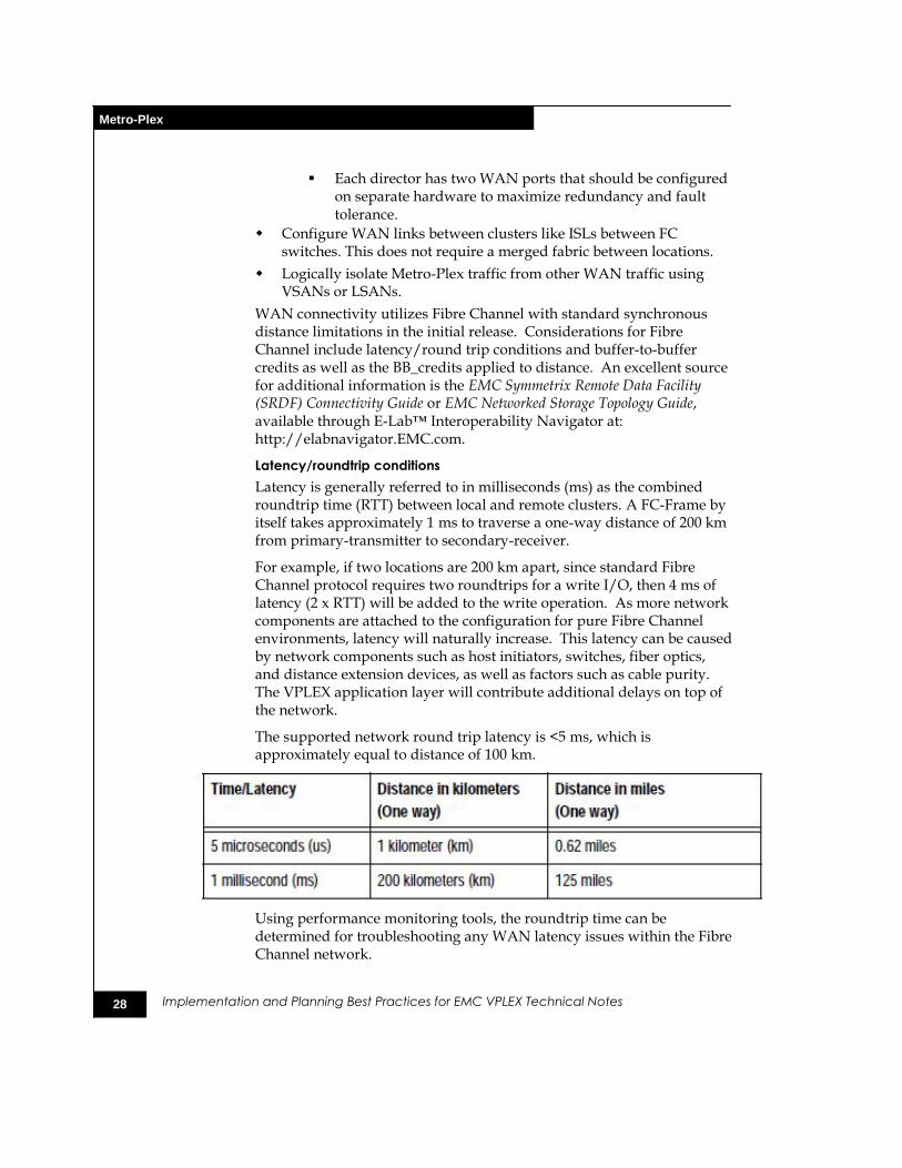
The supported network round trip latency is <5 ms, which is approximately equal to distance of 100 km.
Using performance monitoring tools, the roundtrip time can be determined for troubleshooting any WAN latency issues within the Fibre Channel network.
29
Metro-Plex
Implementation and Planning Best Practices for EMC VPLEX Technical Notes
Buffer-to-buffer credits
Fibre Channel uses the BB_Credits (buffer-to-buffer credits) mechanism for hardware-based flow control. This means that a port has the ability to pace the frame flow into its processing buffers. This mechanism eliminates the need of switching hardware to discard frames due to high congestion. EMC testing has shown this mechanism to be extremely effective in its speed and robustness. Refer to the EMC Networked Storage Topology Guide for proper calculations and settings for your WAN connectivity.
DWDM/SONET configuration
When using DWDM or SONET connectivity between sites, be sure to determine if the two rings have diverse pathing. If it is found that the two rings have diverse pathing and that one path is appreciably longer than the other (that is, latency on the West ring is longer than latency on the East ring), then configure the DWDM/SONET box to prefer the shorter path and only use the longer path in case of failure of the shorter path. An alternative is to use both paths, but this may cause performance issues due to queuing on the directors.
Dual fabrics for inter-cluster communication
A Metro-Plex should be set up with redundant and completely independent Fibre Channel connectivity between clusters. This provides maximum performance, fault isolation, fault tolerance, and availability.
Redundant fabrics are of critical importance due to the fact that when the directors in one cluster have inconsistent connectivity with the directors in the remote cluster, the two clusters will be logically split until the connectivity issues are resolved. This is by design. The firmware requires full connectivity among all directors for protocols such as cache coherence and inter-cluster communication. Without full connectivity, the director will continue to run but will bring the inter-cluster link down. The net result is that all volumes at the losing site will become unavailable as per the pre-defined per volume cluster detach rules. Recovery is simple, but manual. It requires that connectivity be restored between all directors prior to the resumption of I/O operations.
The following is an example fabric configuration:
Site-1 has switches, switch-1A and switch-1B.
Site-2 has switches, switch-2A and switch-2B.
30
Metro-Plex
Implementation and Planning Best Practices for EMC VPLEX Technical Notes
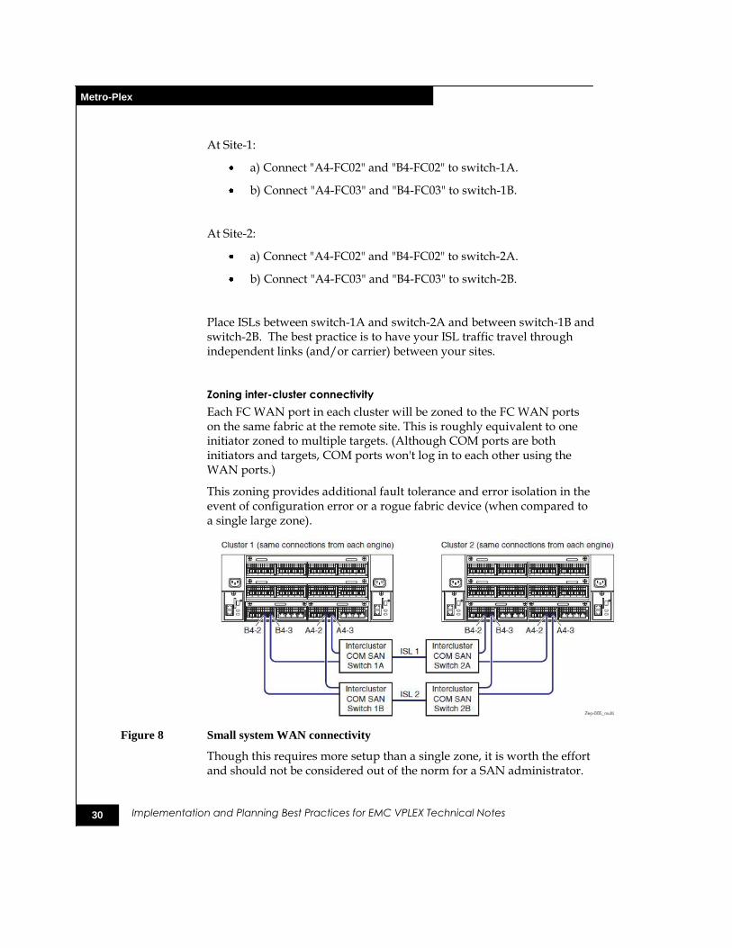
At Site-1:
a) Connect "A4-FC02" and "B4-FC02" to switch-1A.
b) Connect "A4-FC03" and "B4-FC03" to switch-1B.
At Site-2:
a) Connect "A4-FC02" and "B4-FC02" to switch-2A.
b) Connect "A4-FC03" and "B4-FC03" to switch-2B.
Place ISLs between switch-1A and switch-2A and between switch-1B and switch-2B. The best practice is to have your ISL traffic travel through independent links (and/or carrier) between your sites.
Zoning inter-cluster connectivity
Each FC WAN port in each cluster will be zoned to the FC WAN ports on the same fabric at the remote site. This is roughly equivalent to one initiator zoned to multiple targets. (Although COM ports are both initiators and targets, COM ports won't log in to each other using the WAN ports.)
This zoning provides additional fault tolerance and error isolation in the event of configuration error or a rogue fabric device (when compared to a single large zone).
Figure 8 Small system WAN connectivity
Though this requires more setup than a single zone, it is worth the effort and should not be considered out of the norm for a SAN administrator.
31
Metro-Plex
Implementation and Planning Best Practices for EMC VPLEX Technical Notes
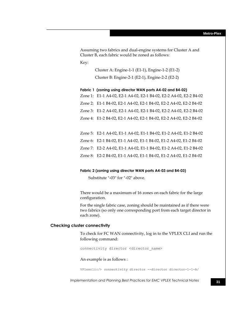
Assuming two fabrics and dual-engine systems for Cluster A and Cluster B, each fabric would be zoned as follows:
Key:
Cluster A: Engine-1-1 (E1-1), Engine-1-2 (E1-2)
Cluster B: Engine-2-1 (E2-1), Engine-2-2 (E2-2)
Fabric 1 (zoning using director WAN ports A4-02 and B4-02)
Zone 1: E1-1 A4-02, E2-1 A4-02, E2-1 B4-02, E2-2 A4-02, E2-2 B4-02
Zone 2: E1-1 B4-02, E2-1 A4-02, E2-1 B4-02, E2-2 A4-02, E2-2 B4-02
Zone 3: E1-2 A4-02, E2-1 A4-02, E2-1 B4-02, E2-2 A4-02, E2-2 B4-02
Zone 4: E1-2 B4-02, E2-1 A4-02, E2-1 B4-02, E2-2 A4-02, E2-2 B4-02
Zone 5: E2-1 A4-02, E1-1 A4-02, E1-1 B4-02, E1-2 A4-02, E1-2 B4-02
Zone 6: E2-1 B4-02, E1-1 A4-02, E1-1 B4-02, E1-2 A4-02, E1-2 B4-02
Zone 7: E2-2 A4-02, E1-1 A4-02, E1-1 B4-02, E1-2 A4-02, E1-2 B4-02
Zone 8: E2-2 B4-02, E1-1 A4-02, E1-1 B4-02, E1-2 A4-02, E1-2 B4-02
Fabric 2 (zoning using director WAN ports A4-03 and B4-03)
Substitute "-03" for "-02" above.
There would be a maximum of 16 zones on each fabric for the large configuration.
For the single fabric case, zoning should be maintained as if there were two fabrics (so only one corresponding port from each target director in each zone).
Checking cluster connectivity
To check for FC WAN connectivity, log in to the VPLEX CLI and run the
following command: connectivity director <director_name>
An example is as follows :
VPlexcli:/> connectivity director --director director-1-1-A/
32
Metro-Plex
Implementation and Planning Best Practices for EMC VPLEX Technical Notes
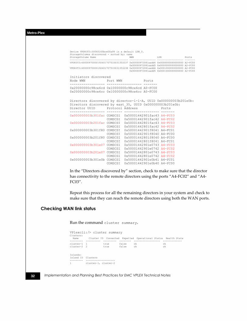
Device VPD83T3:50060160bce00a99 is a default LUN_0.
StorageVolumes discovered - sorted by: name
StorageVolume Name WWN LUN Ports
---------------------------------------- ------------------ ------------------ -------
VPD83T3:60000970000192601707533031353237 0x50000972081aadd4 0x0000000000000000 A2-FC00
0x50000972081aadd5 0x0000000000000000 A2-FC00
VPD83T3:60000970000192601707533031353238 0x50000972081aadd4 0x0001000000000000 A2-FC00
0x50000972081aadd5 0x0001000000000000 A2-FC00
Initiators discovered
Node WWN Port WWN Ports
------------------ ------------------ -------
0x20000000c98ce6cd 0x10000000c98ce6cd A0-FC00
0x20000000c98ce6cc 0x10000000c98ce6cc A0-FC00
Directors discovered by director-1-1-A, UUID 0x000000003b201e0b:
Directors discovered by east_35, UUID 0x000000003b201e0b:
Director UUID Protocol Address Ports
------------------ -------- ------------------ -------
0x000000003b301fac COMSCSI 0x50001442901fac43 A4-FC03
COMSCSI 0x50001442901fac42 A4-FC02
0x000000003b201fac COMSCSI 0x50001442801fac43 A4-FC03
COMSCSI 0x50001442801fac42 A4-FC02
0x000000003b301f80 COMSCSI 0x50001442901f8041 A4-FC01
COMSCSI 0x50001442901f8040 A4-FC00
0x000000003b201f80 COMSCSI 0x50001442801f8040 A4-FC00
COMSCSI 0x50001442801f8041 A4-FC01
0x000000003b301e07 COMSCSI 0x50001442901e0743 A4-FC03
COMSCSI 0x50001442901e0742 A4-FC02
0x000000003b201e07 COMSCSI 0x50001442801e0743 A4-FC03
COMSCSI 0x50001442801e0742 A4-FC02
0x000000003b301e0b COMSCSI 0x50001442901e0b41 A4-FC01
COMSCSI 0x50001442901e0b40 A4-FC00
In the “Directors discovered by” section, check to make sure that the director
has connectivity to the remote directors using the ports “A4-FC02” and “A4-
FC03”.
Repeat this process for all the remaining directors in your system and check to
make sure that they can reach the remote directors using both the WAN ports.
Checking WAN link status
Run the command cluster summary.
VPlexcli:/> cluster summary Clusters:
Name Cluster ID Connected Expelled Operational Status Health State
--------- ---------- --------- -------- ------------------ -------------
cluster-1 1 true false ok ok
cluster-2 2 true false ok ok
Islands:
Island ID Clusters
--------- --------------------
1 cluster-1, cluster-2
33
Metro-Plex
Implementation and Planning Best Practices for EMC VPLEX Technical Notes
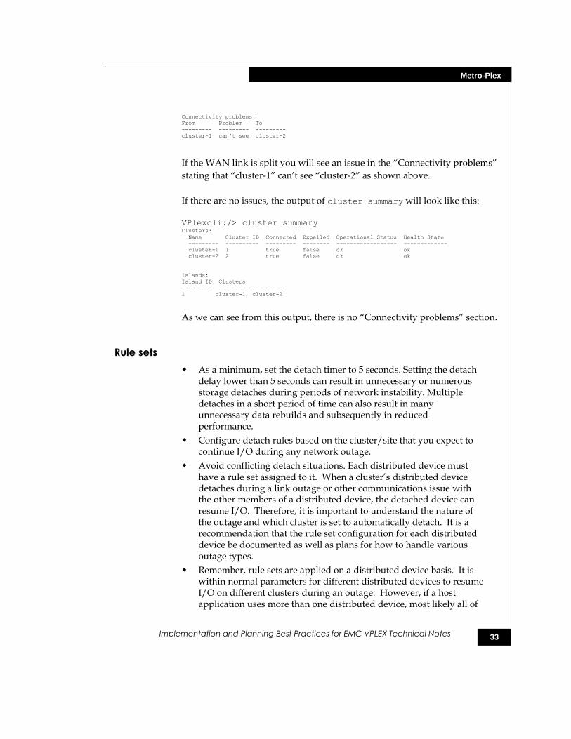
Connectivity problems:
From Problem To
--------- --------- ---------
cluster-1 can't see cluster-2
If the WAN link is split you will see an issue in the “Connectivity problems”
stating that “cluster-1” can’t see “cluster-2” as shown above.
If there are no issues, the output of cluster summary will look like this:
VPlexcli:/> cluster summary Clusters:
Name Cluster ID Connected Expelled Operational Status Health State
--------- ---------- --------- -------- ------------------ -------------
cluster-1 1 true false ok ok
cluster-2 2 true false ok ok
Islands:
Island ID Clusters
--------- --------------------
1 cluster-1, cluster-2
As we can see from this output, there is no “Connectivity problems” section.
Rule sets
As a minimum, set the detach timer to 5 seconds. Setting the detach delay lower than 5 seconds can result in unnecessary or numerous storage detaches during periods of network instability. Multiple detaches in a short period of time can also result in many unnecessary data rebuilds and subsequently in reduced performance.
Configure detach rules based on the cluster/site that you expect to continue I/O during any network outage.
Avoid conflicting detach situations. Each distributed device must have a rule set assigned to it. When a cluster’s distributed device detaches during a link outage or other communications issue with the other members of a distributed device, the detached device can resume I/O. Therefore, it is important to understand the nature of the outage and which cluster is set to automatically detach. It is a recommendation that the rule set configuration for each distributed device be documented as well as plans for how to handle various outage types.
Remember, rule sets are applied on a distributed device basis. It is within normal parameters for different distributed devices to resume I/O on different clusters during an outage. However, if a host application uses more than one distributed device, most likely all of
34
A dministration recommendations
Implementation and Planning Best Practices for EMC VPLEX Technical Notes
the distributed devices for that application should have the same rule set to resume I/O on the same cluster
Administration recommendations
Use Access Control Lists to restrict administrator actions on LUNs under VPLEX
management
A serious DU or DL potentially exists if the administrator of the back-end array accidentally or purposely exposes a LUN that has been claimed by VPLEX directly to a non-VPLEX initiator (or to a different VPLEX system, for that manner). Under no circumstances should a volume that is virtualized by VPLEX be presented directly to another initiator. In all circumstances, this is a configuration error.
To prevent the above scenario, it is a best practice to put in place barriers that would prevent or make difficult the above scenarios. One such barrier that can be used on a Symmetrix is to configure Access Control Lists (ACLs) that prevent the administrator from changing the LUN masking for any volume that is masked to VPLEX. Also, Symmetrix ACLs are only available on recent versions of Symmetrix firmware.
Naming conventions
For device/volume naming, users should decide early on whether they will name volumes after underlying storage or prefer to have volumes named after the data they contain. This is because it will become important on their first migration when they have to decide whether to rename the volume after the target device or keep the current name.
During the course of managing your virtualized environment you will create various virtual storage objects (extents, devices, virtual volumes, storage views, and so on). Each of these objects has a name. Some commands create default names. The following name rules are enforced for all names:
Names can consist of:
Upper and lowercase letters
Digits
Underscores
Dashes
Spaces are not permitted.
Names must start with either a letter or underscore.
The maximum name length is 63 characters. Some automated processes like migrations rename devices by appending date stamp
35
A dministration recommendations
Implementation and Planning Best Practices for EMC VPLEX Technical Notes
information to an object name. If the original object name is close to the 63-character limit, this process will fail because it won’t be able to set the new name. It is best to keep names closer to a maximum of 40 characters.
If you use the CLI more often and take advantage of tab completion, you may want to keep the unique part of a name closer to the beginning to cut down on typing.
More importantly are the naming conventions used for the storage objects. The following are some naming convention suggestions. Remember that the naming convention should be decided based on the needs of the environment.
Storage volumes - Indicate the storage array and other identifying info.
Extents - Keep consistent with storage volumes (default).
Devices - May reference information from the storage volume, but it is more important to make some reference to the host/application/purpose.
Virtual volumes – The default is named after the top-level device, appending ―_vol‖.
Additionally, try not to load names with too much information.
Log or capture CLI sessions
It is recommended that VPLEX administrators use the capture command to log activities. This has various advantages that become more valuable if there are multiple administrators. Captured sessions help with:
Accountability/Auditing
Ease of repeating tasks
Note taking
Support calls
Capture sessions can also be used to document best practices and procedures that you develop specifically to your environment.
It is highly recommended that you start a capture session before any important admin tasks, especially before NDU.
Monitoring VPLEX
The EMC VPLEX CLI Guide has more information monitoring VPLEX.
Make regular use of summary and reporting commands to monitor the VPLEX. These commands can provide a quick overview of how the system is configured and its general health. It is recommended that you
36
Summary
Implementation and Planning Best Practices for EMC VPLEX Technical Notes
become familiar with and develop your own set of routine commands to do a quick check of the system.
The following commands are used to monitor clusters and system health:
ndu pre-check
batch-migrate summary
cluster summary
ds summary
export port summary
export storage-view summary
extent summary
local-device summary
storage-volume summary
virtual-volume summary
rebuild status
validate-system-configuration
report capacity-clusters
vpn status (Metro-Plex only)
Management server date/time across Metro-Plex
Keep clocks on Metro-Plex management servers in sync for log event correlation. This will make troubleshooting or auditing the system easier.
Summary
VPLEX provides another layer of abstraction between the host and the storage array. The more these layers continue to expand into IT infrastructures, the more important HA capabilities become. VPLEX inherently has some HA attributes, but it also requires careful planning to take full advantage of the HA capabilities in many of the VPLEX components. Further, carefully designed SAN planning guidelines must be followed to complement the HA capability of the VPLEX configuration described in these technical notes with the overall SAN used in the IT infrastructure.
37
Summary
Implementation and Planning Best Practices for EMC VPLEX Technical Notes
Copyright © 2010 EMC Corporation. All Rights Reserved. EMC believes the information in this publication is accurate as of its publication date. The information is subject to change without notice.
THE INFORMATION IN THIS PUBLICATION IS PROVIDED "AS IS." EMC CORPORATION MAKES NO REPRESENTATIONS OR WARRANTIES OF ANY KIND WITH RESPECT TO THE INFORMATION IN THIS PUBLICATION, AND SPECIFICALLY DISCLAIMS IMPLIED WARRANTIES OF MERCHANTABILITY OR FITNESS FOR A PARTICULAR PURPOSE.
Use, copying, and distribution of any EMC software described in this publication requires an applicable software license.
For the most up-to-date listing of EMC product names, see EMC Corporation Trademarks on EMC.com.
All other trademarks used herein are the property of their respective owners.