Impact Testing and Analysis of Composites for Aircraft ... · PDF fileNASA/TM-2002-211493...
19
NASA/TM-2002-211493 Impact Testing and Analysis of Composites for Aircraft Engine Fan Cases Gary D. Roberts and Duane M. Revilock Glenn Research Center, Cleveland, Ohio Wieslaw K. Binienda and Walter Z. Nie University of Akron, Akron, Ohio S. Ben Mackenzie and Kevin B. Todd Saint-Gobain Performance Plastics, Ravenna, Ohio April 2002 https://ntrs.nasa.gov/search.jsp?R=20020061387 2018-05-19T02:19:43+00:00Z
Transcript of Impact Testing and Analysis of Composites for Aircraft ... · PDF fileNASA/TM-2002-211493...
NASA/TM-2002-211493
Impact Testing and Analysis of Composites for Aircraft Engine Fan Cases
Gary D. Roberts and Duane M. Revilock Glenn Research Center, Cleveland, Ohio
Wieslaw K. Binienda and Walter Z. Nie University of Akron, Akron, Ohio
S. Ben Mackenzie and Kevin B. Todd Saint-Gobain Performance Plastics, Ravenna, Ohio
April 2002
https://ntrs.nasa.gov/search.jsp?R=20020061387 2018-05-19T02:19:43+00:00Z
The NASA STI Program Office ... in Profile
Since its founding, NASA has been dedicated to the advancement of aeronautics and space science. The NASA Scientific and Technical Information (STI) Program Office plays a key part in helping NASA maintain this important role.
The NASA STI Program Office is operated by Langley Research Center, the Lead Center for NASA's scientific and technical information. The NASA STI Program Office provides access to the NASA STI Database, the largest collection of aeronautical and space science STI in the world. The Program Office is also NASA's institutional mechanism for disseminating the results of its research and development activities. These results are published by NASA in the NASA STI Report Series, which includes the following report types:
• TECHNICAL PUBUCATION. Reports of completed research or a major significant phase of research that present the results of NASA programs and include extensive data or theoretical analysis. Includes compilations of significant scientific and technical data and information deemed to be of continuing reference value. NASA's counterpart of peerreviewed formal professional papers but has less stringent limitations on manuscript length and extent of graphic presentations.
• TECHNICAL MEMORANDUM. Scientific and technical findings that are preliminary or of specialized interest, e.g., quick release reports, working papers, and bibliographies that contain minimal annotation. Does not contain extensive analysis.
• CONTRACTOR REPORT. Scientific and technical findings by NASA-sponsored contractors and grantees.
• CONFERENCE PUBUCATION. Collected papers from scientific and technical conferences, symposia, seminars, or other meetings sponsored or cosponsored by NASA.
• SPECIAL PUBUCATION. Scientific, technical, or historical information from NASA programs, projects, and missions,
. often concerned with subjects having substantial public interest.
• TECHNICAL TRANSLATION. Englishlanguage translations of foreign scientific and technical material pertinent to NASA's mission.
Specialized services that complement the STI Program Office's diverse offerings include creating custom thesauri, building customized data bases, organizing and publishing research results ... even providing videos.
For more information about the NASA STI Program Office, see the following:
• Access the NASA STI Program Home Page at http://www.sti.nasa.gov
• E-mail your question via the Internet to [email protected]
• Fax your question to the NASA Access Help Desk at 301-621--0134
• Telephone the NASA Access Help Desk at 301-621--0390
• Write to: NASA Access Help Desk NASA Center for AeroSpace Information 7121 Standard Drive Hanover, MD 21076

NASA/TM-2002-211493
Impact Testing and Analysis of Composites for Aircraft Engine Fan Cases
Gary D. Roberts and Duane M. Revilock Glenn Research Center, Cleveland, Ohio
Wieslaw K. Binienda and Walter Z. Nie University of Akron, Akron, Ohio
S. Ben Mackenzie and Kevin B. Todd Saint-Gobain Performance Plastics, Ravenna, Ohio
National Aeronautics and Space Administration
Glenn Research Center
April 2002

Trade names or manufacturers' names are used in this report for identification only. This usage does not constitute an official endorsement, either expressed or implied, by the National
Aeronautics and Space Administration.
Available from
NASA Center for Aerospace Information 7121 Standard Drive
National Technical Information Service 5285 Port Royal Road Springfield, VA 22100 Hanover, MD 21076
Available electronically at http://g:ltrs.g:rc.nasa.g:ov IGLTRS

Impact Testing and Analysis of Composites for Aircraft Engine Fan Cases
Gary D. Roberts and Duane M. Revilock National Aeronautics and Space Administration
Glenn Research Center Cleveland, Ohio 44135
Wieslaw K. Binienda and Walter Z. Nie University of Akron Akron, Ohio 44325
S. Ben Mackenzie and Kevin B. Todd Saint-Gobain Performance Plastics
Ravenna, Ohio 44266
ABSTRACT
The fan case in a j et engine is a heavy structure because of its size and because of the requirement that it contain a blade released during engine operation. Composite materials offer the potential for reducing the weight of the case. Efficient design, test, and analysis methods are needed to efficiently evaluate the large number of potential composite materials and design concepts. The type of damage expected in a composite case under blade-out conditions was evaluated using a subscale test in which a glass/epoxy composite half-ring target was impacted with a wedge-shaped titanium projectile. Fiber shearing occurred near points of contact between the projectile and target. Delamination and tearing occurred on a larger scale. These damage modes were reproduced in a simpler test in which flat glass/epoxy composites were impacted with a blunt cylindrical projectile. A surface layer of ceramic eliminated fiber shear fracture but did not reduce delamination. Tests on 3D woven carbon/epoxy composites indicated that transverse reinforcement is effective in reducing delamination. A 91 cm (36 in.) diameter fullring subcomponent was proposed for larger scale testing of these and other composite concepts. Explicit, transient, fmite element analyses indicated that a full-ring test is needed to simulate complete impact dynamics, but simpler tests using smaller ring sections are adequate when evaluation of initial impact damage is the primary concern.
INTRODUCTION
High bypass ratio turbofan engines are used to power modem large commercial aircraft because of their high overall efficiency, high thrust at low flight speeds, low jet velocity, and low fuel consumption (Mattingly 1996). The fan case is the largest structural component in these engines. Currently, metal alloys are used for the case material in all commercial engines. Use of composite materials could significantly reduce the weight ofthe fan case, however technical feasibility and cost effectiveness first need to be demonstrated. High material and fabrication costs have limited the use of composites in many aerospace applications. However, fiber costs
NASAffM-2002-211493

are projected to decrease substantially, and rapid developments are occurring in the area oflow cost manufacturing of large composite structures. The cost of developing and certifying a composite design remains as a potential obstacle. Better analysis techniques could reduce the cost of development by allowing materials and design options to be tested more reliably in laboratory scale impact tests. This would allow more design options to be tested and better refinement of preliminary design concepts before committing to the expense of fabricating and testing a full scale fan case.
Full scale testing of a fan case is expensive because of the complex nature of a blade-out event and because of the safety issues involved. Although loss of a fan blade during flight is a rare event, damage caused by the released blade can be catastrophic. The fan containment system must either contain the blade or cause it to be ejected from the engine in a direction that will not cause damage to the aircraft. The fan case must also maintain structural integrity during the large transient loading that it experiences before full engine shut down. These loads are induced by impact of the released blade, rubbing of remaining rotating blades, and vibrations from the unbalanced rotor. Before an engine can be used in commercial service, the performance of the fan containment system must be demonstrated in a full-scale engine blade-out test according to Federal Aviation Regulations (FAA). In this test, a fan blade is released at full operating speed. Since the engine is destroyed in this test, it is usually the final test performed in the certification process for a new engine. Any changes to the design of the fan case at this stage can significantly increase cost and delay certification of the engine. If a traditional metal material is used for the fan case, the risk of failing the certification test is minimized because the design methodology is supported by a large experience base. This experience includes testing at all levels (material, subcomponent, subscale, and full scale) as well as methods for design and analysis. Explicit finite element analysis is beginning to be used earlier in the design cycle for metal fan cases to shorten development time, reduce testing cost, and reduce the risk of failure for the final design. This approach is also used in the automobile industry where explicit fmite element analysis is used in conjunction with instrumented crash tests to improve vehicle crashworthiness. Recent advances in the use of explicit codes such as LsDyna3D and ABAQUS/Explicit allow numerical testing of an entire car before even a single car body is manufactured. A similar approach is needed to overcome the large development cost and technical risk associated with using a new composite fan case design. This is a particularly important issue for composites because the large number of possibilities for fiber orientation, failure mode, materials, and manufacturing method make a development program based on testing alone impractical. Use offinite element analysis to assist design is most effective when a design methodology already exists and a large experience base is available for validation of the analysis methods. Unfortunately, test data for composite containment cases is limited, and explicit firiite element methods for analyzing composite failure are not well developed.
Ballistic impact tests performed using gas guns are often used in place of more expensive spin pit tests to screen preliminary design concepts. A limitation of this approach is that impact tests can not simulate the dynamics of a released rotating blade, including interactions with adjacent blades. However, an impact test can give valuable information about a case design (potential failure modes, deflection, etc.) if a full scale case is impacted by a realistic projectile (representing a released blade fragment) under conditions (speed, orientation) derived from a particular engine design. Simpler tests are often used for a relative comparison of materials and
NASAlTM-2002-211493 2

design concepts. These test use a sub scale case, a subcomponent, or a flat panel as the target and a geometrically simple projectile. The projectile shape and impact velocity are often selected based on blade speed and failure modes observed in a particular engine. However, detailed analysis of both the test method and the full engine case design is needed in order to properly evaluate the test data. The desired result from the impact test depends on the containment approach being considered. Two design approaches (hardwall and softwall) are currently used in commercial engines for blade containment. In the "hardwall" design, the wall thiclrness near the blade impact site is made sufficiently thick to resist penetration, and ribs are used to control global stiffness. In this design, penetration at the impact site must not occur and damage must be limited so that global stiffness and strength of the structure are maintained. In the "softwall" design, the case is penetrated by the blade and captured by an outer wrap of fabric. In this design, stiffness is provided by either an isogrid or honeycomb structure on the case. Although the blade is allowed to penetrate the case in the softwall design, the perforated area must be kept as small as possible to limit subsequent damage to the case. Lane (Lane) has reported design equations used to determine wall thiclrness for hardwall contaimnent cases and to determine thiclrness of the fabric wrap for softwall containment cases. These equations have been determined for metal fan cases and are not expected to apply to a composite case, Design equations for composites cases must take into account the complex damage processes that occur during impact of composites. Low velocity impact of composites can cause extensive internal damage (microcracking, delamination) with little visible surface damage (Greszczuk 1982). Similar damage modes have been observed in high velocity tests. High velocity tests on composites using flat, hemispherical, and conical projectiles have shown shear failure in plies nearest the impact surface to be the initial failure mode (Mines et al. 1999). Subsequent damage modes depend on the materials, fiber architecture, and ply lay-ups, but often include delamination and fiber tensile failure in the interior or near the back surface plies. Similar damage modes are expected to occur in a composite containment case during a blade-out event, and methods for limiting the growth of this damage during post impact loading must be considered in the design. Some proprietary test data and analysis methods have been generated in development programs conducted by engine manufacturers. However, additional data measured at impact velocities and energies representative of a blade-out event are needed for developing reliable methods for design, test, and analysis of composite fan cases.
In this paper, failure modes and impact resistance of some composite materials are evaluated using ballistic impact tests on flat and half-ring composite panels. A larger full-ring structure is proposed as a possible subcomponent that can be fabricated and tested at a reasonable cost. Explicit fmite element analysis is used to evaluate impact dynamics for the proposed subcomponent test.
COMPOSITE IMPACT TESTS
In order to identify expected damage modes in a composite containment ring under simulated blade-out conditions, a 38.1 cm (15 in.) diameter, 1.07 cm (0.42 in.) thick glass/epoxy half ring was impacted with a wedge-shaped titanium projectile at a velocity of259 mls (850 fils). The composite half ring was made using 32 plies of style 6781 S2 glass fabric with a [0/90/45/-45]s layup. The 330 g (0.73 Ib) wedge was 12.7 cm (5 in.) long by 9.5 cm (3.75 in.) wide with the
NASAlTM-2002-211493 3

thickness increasing from 0.32 cm (118 in.) at the thin edge to 0.95 cm (3/8 in.) at the thick edge to simulate the mass distribution of a fan blade fragment. To simulate the blade dynamics, the desired orientation of the wedge was 45° from the horizontal with the thin edge of the wedge making contact first. The thin edge curls during the initial impact. The wedge then rotates until the thick edge makes a more damaging second impact. Figure 1 shows the wedge and a side view of the 38.1 cm (15 in.) half-ring after impact. Local fiber shear fracture occurs along the lines where the thin and the thick edges of the wedge make contact. Extensive delamination occurs throughout the composite, and tearing occurs in plies near the back surface. Damage also appears to be concentrated at some points around the edges where the half-ring was held in place by the metal fixtures.
The damage evident in Fig. 1 indicates that a composite hardwall containment system will require use of a surface layer that is capable of eliminating local shear failure. In addition, some method for controlling delamination will be needed. Lightweight materials and structures that are capable of absorbing a large amount of energy have been developed for armor applications. Although most of these materials are not suitable for use as the main structural material in a containment case, a recent report (DOT 1997) has examined the feasibility of applying some of these armor concepts to commercial aircraft in the form of protective barriers that could enhance aircraft survivability in the event of an uncontained engine failure. One such concept is to place a ceramic plate on the impact surface of the composite. In armor materials the ceramic serves to fragment the projectile and spread the impact load over a larger area of the backing plate. Projectile fragmentation occurs at very high impact velocities as a result of shock waves within the projectile. This process is unlikely to occur with large titanium blade fragments impacting a case at velocities characteristic of a blade-out event. However, a ceramic layer may still be useful for spreading the impact load and blunting sharp blade fragments. Delamination can be controlled by reinforcement in the transverse direction by processes such as stitching, pinning, or 3D weaving. Evaluation of these concepts using the test configuration shown in Fig. 1 would be expensive and time consuming. The high cost is a result of fabrication costs for the panels, fabrication costs for the projectile, and the cost of performing the test. Although the proposed concepts would not necessarily be too expensive for commercial production, fabrication of a small number oftest panels can be very costly. For example, set-up costs for weaving represent a small part of the total cost for a large production run but a large part of the cost for fabrication of a small number of panels. In addition, scheduling such a small run often cannot be done in a timely manner. The wedge used for the test shown in Fig. 1 requires machining of a block of titanium. A simpler projectile that could be cut from stock material would be less expensive and more readily available. The complexity of the impact test shown in Fig. I causes variability in the test results. Since the projectile is not cylindrical or spherical, it must be mounted in a cylindrical container (sabot) in order to fit into the barrel of the gas gun. The 45° pitch angle is achieved by bonding the titanium wedge to a 45° prism-shaped wood platform within the sabot. Imprints of the wedge on the test panel and high-speed video of the projectile during the test have shown that the orientation of the wedge often deviates in pitch and roll from the desired orientation. Deviation in the location of impact also occurs. The location and orientation of the blade have a large effect on the damage induce by impact. Damage induced by the first contact of the thin edge of the wedge is more severe for pitch angles less than 45°. Rotation of the wedge also causes more severe damage because the wedge makes contact at its comers rather than along its edges. All of these factors indicate that a simpler, less expensive test would be
NASAlTM-2002-211493 4

preferable for preliminary screening of composite concepts. A simpler test was therefore used to evaluate the performance of a ceramic layer on a glass/epoxy composite and the performance of 3D woven materials. Some justification based on observed failure modes is discussed below. Analysis of impact dynamics for a full-ring structure, discussed in a later section, provides further support for the use of the simpler test method.
Small 18 x 18 cm (7 x 7 in.) flat panels were impacted with flat-ended cylindrical titanium projectiles (2.54 cm long, 1.27 cm diameter). Panel and projectile shapes are shown in Fig. 2. The blunt projectile shape was chosen in an attempt to induce failure modes in the small panels that are similar to the failure modes observed in the half-ring when impacted by edges of the wedge-shaped projectile. Preliminary tests on flat composite panels with various fiber and matrix materials demonstrated that the impact damage did have features similar to those shown in Fig. 1. Fiber shear fracture occurred on the front surface, delamination occurred in the interior, and fiber tearing occurred on the back surface. The ballistic limit was determined by testing approximately 6 to 8 panels over a range of impact velocities. Ideally, the ballistic limit is the velocity below which the projectile does not perforate the panel and above which the projectile completely perforates the panel. The ballistic limit can then be defined as the average of the highest velocity that did not perforate and the lowest velocity that completely perforates the panels. In practice, there is sometimes a small velocity region near the ballistic limit in which non-perforation and perforation overlap. In addition, failure may be defmed by a criterion other than complete perforation. For example, a plate may be considered to fail the test if a crack propagates through the panel, even though the projectile does not perforate the panel. The above definition for ballistic limit can still be used, as long as the failure criterion is defined.
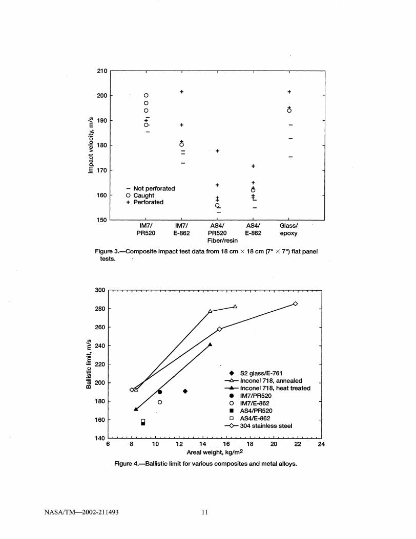
Impact test data for five different types of composite panels are shown in Fig. 3. For these composite panels there was a velocity region near the ballistic limit within which the projectile was caught in the panel. This was interpreted as perforation (or failure) for the purpose of calculating the ballistic limit. The ballistic limits calculated from the data in Fig. 3 are shown in Fig. 4 along with the ballistic limits that have been measured for 304 stainless steel (unpublished) and for Inconel-718 (Pereira 2001). The stainless steel alloy was chosen for comparison because it has been used in commercial fan cases. The ballistic limits of Inconel-718 in the annealed and heat treated forms are shown to indicate the range of properties possible for some alloys by heat treatment. The thickness (or areal weight) range of the metal alloy panels used to obtain the data in Fig. 4 was chosen so that the ballistic limits would fall within the range of velocities which are characteristic of blade fragments during a blade-out. It is useful to have data over a range of areal weights because it is usually not feasible to fabricate panels of different materials with exactly equal areal weights for direct comparison.
The first composite concept evaluated was the use ofa 1.9 mm (0.075 in.) thick silicon carbide ceramic layer to reduce the extent of shear failure at the impact surface. Unidirectional 18 x 18 cm (7 x 7in.) glass/epoxy panels were cut from a larger 41.9 x 96.5 cm (16.5 x 38.0 in.) panel that was made by hand lay-up of 28 plies of style 6781 S2 glass/E-761 epoxy prepreg with vacuum bag cure. Six of the 18 x 18 cm (7 x 7 in.) panels were used to measure the ballistic limit ofthe composite (Fig. 3). In Fig. 4, the ballistic limit ofthe S2 glass/E-761 composite is 191 mls (626 fils), which is well below that of the metal alloys at an equivalent areal weight. Figures 2( a) and (b) show the front and back surfaces after impact for glass/epoxy panels with
NASAfTM-2002-211493 5
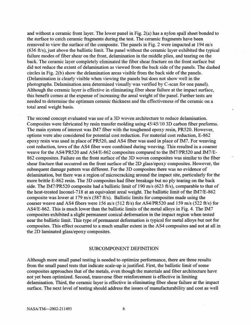
and without a ceramic front layer. The lower panel in Fig. 2(a) has a nylon spall sheet bonded to the surface to catch ceramic fragments during the test. The ceramic fragments have been removed to view the surface of the composite. The panels in Fig. 2 were impacted at 194 mls (636 ftls), just above the ballistic limit. The panel without the ceramic layer exhibited the typical failure modes of fiber shear on the front, delamination in the middle plies, and tearing on the back. The ceramic layer completely eliminated the fiber shear fracture on the front surface but did not reduce the extent of delamination as viewed from the back side of the panels. The dashed circles in Fig. 2(b) show the delamination areas visible from the back side of the panels. (Delamination is clearly visible when viewing the panels but does not show well in the photographs. Delamination area detennined visually was verified by C-scan for one panel). Although the ceramic layer is effective in eliminating fiber shear failure at the impact surface, this benefit comes at the expense of increasing the areal weight of the panel. Further tests are needed to detennine the optimum ceramic thickness and the effectiveness of the ceramic on a total areal weight basis.
The second concept evaluated was use of a 3D woven architecture to reduce delamination. Composites were fabricated by resin transfer molding using 45/4511 0 3D carbon fiber preforms. The main system of interest was IM7 fiber with the toughened epoxy resin, PR520. However, options were also considered for potential cost reduction. For material cost reduction, E-862 epoxy resin was used in place of PR520, and AS4 fiber was used in place of IM7. For weaving cost reduction, tows of the AS4 fiber were combined during weaving. This resulted in a coarser weave for the AS4/PR520 and AS4/E-862 composites compared to the IM7IPR520 and IM7/E-862 composites. Failure on the front surface of the 3D woven composites was similar to the fiber shear fracture that occurred on the front surface of the 2D glass/epoxy composites. However, the subsequent damage pattern was different. For the 3D composites there was no evidence of delamination, but there was a region of microcracking around the impact site, particularly for the more brittle E-862 resin. The 3D composites had fiber breakage but no ply tearing on the back side. The IM7IPR520 composite had a ballistic limit of 190 mls (623 fils), comparable to that of the heat-treated Inconel-718 at an equivalent areal weight. The ballistic limit of the IM7/E-862 composite was lower at 179 mls (587 ft/s). Ballistic limits for composites made using the coarser weave and AS4 fibers were 156 mls (512 fils) for AS4/PR520 and 159 mls (522 fils) for AS4/E-862. This is much lower than the ballistic limits of the metal alloys in Fig. 4. The IM7 composites exhibited a slight permanent conical defonnation in the impact region when tested near the ballistic limit. This type of pennanent deformation is typical for metal alloys but not for composites. This effect occurred to a much smaller extent in the AS4 composites and not at all in the 2D laminated glass/epoxy composites.
SUBCOMPONENT DEFINITION
Although more small panel testing is needed to optimize perfonnance, there are three results from the small panel tests that indicate scale-up is justified. First, the ballistic limit of some composites approaches that of the metals, even though the materials and fiber architecture have not yet been optimized. Second, transverse fiber reinforcement is effective in limiting delamination. Third, the ceramic layer is effective in eliminating fiber shear failure at the impact surface. The next level of testing should address the issues of manufacturability and cost as well
NASAlTM-2002-211493 6

as demonstrating technical feasibility at a larger scale. The subcomponent test in Fig. 5 is proposed for this purpose. The 91 cm (36 in.) diameter ring could be manufactured by hand layup, filament winding, or some other low cost automated process. If the composite material properties are not strain rate dependent, scaling of displacement, contact forces, and strains from a small test to a larger prototype is possible, but scaling of damage is not (Abrate 1998). Since scaling of damage is not possible and strain rate dependence is likely, results from the small panel tests can not be used directly to predict performance of the same material in a larger subcomponent design. Explicit finite element analysis could be useful for correlating results at various test scales. However high strain rate data is generally not available and advancement is needed in composite damage models. In spite of these limitations, analysis of global dynamics using finite element methods is useful for analyzing some details of the impact test method.
FINITE ELEMENT ANALYSIS
Although reliable failure models and strain rate dependent composite materials properties are not available to perform an exact analysis ofthe impact test proposed in Fig. 5, some analysis is needed to examine the dynamics of the impact event. Ultimately, issues such as the contact time during impact, characteristic time for propagation of global deformation waves, maximum deflection of the containment ring, dynamics of the projectile, and boundary conditions imposed by the test fixtures need to be analyzed and compared to data from real blade-out events. A preliminary analysis is reported in this paper. Explicit, transient, finite element analysis of the proposed sUbcomponent in Fig. 5 was performed using the commercial code ABAQUS/Explicit (ABAQUS). The overall dynamics ofthe ring during and after impact was examined in order to evaluate the full-ring test configuration and alternative configurations using sections of the ring with either free or fixed boundary conditions. In this analysis the impact velocity was 183 mls (600 fils) and the composite ring was taken to be 0.76 cm (0.3 in.) thick with the following properties, which are representative of a glass/epoxy laminate with a 0°/90° layup.
Ell= E22= 17.2 GPa (2.5x10⁶ psi) G12= 6.89 GPa (I.OXI 06 psi) G13= G23= 4.14 GPa (6.0x10⁵ psi) '012= '021= 0.14 p= 1716 kg/m3 (0.0619Ib/in3)
Linear elastic, rate independent properties were used, and damage was not considered for this preliminary analysis. Mesh density was determined by performing repeated analyses with increasing mesh density until increasing the mesh density resulted in no significant change in results. The projectile was a flat circular cylinder with diameter of 11.4 cm (4.5 in.), thickness of 1.9 cm (0.75 in.), and mass of 0.86 kg (1.9Ib). It was modeled as a rigid body with a density of 4368 kg/m3 (0.258 Ib/in3). The ring was inclined at an angle of 22° to the horizontal. The mesh in Fig. 6 along with the symmetry condition about the mid plane was used for the full-ring analysis. Half-ring and quarter-ring structures with both free and fixed boundary conditions were also analyzed. Four-node thin shell S4R elements were used for the shell. Six-node and eight-node solid C3D6 and C3D8R elements were used for the projectile.
NASAffM-2002-211493 7

Deformation of the full-ring structure at various time intervals is shown in Fig. 7. At 0.11 ms the case begins to bulge as the top edge ofthe projectile pushes on the case. At 0.31 ms the center of the case bulges as the center of mass of the projectile contacts and pushes on the case. At later times the projectile rebounds, and a flexural wave begins to travel around the case. The horizontal displacement and velocity of the upper point on the projectile are shown in Figs. 8(a) and (b) for the full-ring model along with the results for the half- and quarter-ring models with both free and fixed boundary conditions. In the time interval from 0 to 0.25 ms, contact between the upper point on the projectile and the case causes the case to bulge and causes the projectile to slow down and rotate. Between 0.25 and 0.7 ms the center point of the projectile contacts the case and causes the case to bulge further. This causes the velocity of the upper point on the projectile to increase during this time interval. Between 0.7 and 1.0 ms the projectile rebounds from the case. After 1.0 ms the projectile releases from the case and continues to travel at constant velocity. In the time intervalfrom 0 to 1.0 ms, while the projectile is in contact with the case, the motion ofthe projectile is very similar for the full-ring and the half-rings with both free and fixed boundary conditions. The motion of the projectile impacting the quarter-rings deviates from the half- and full-ring configurations after 0.4 ms when the initial impact ofthe upper point on the projectile with the case is complete. The same conclusions result when displacements and velocities for other points on the ring are analyzed. These results suggest that a half-ring configuration could be used in place of a full-ring to evaluate local damage. Either free or fixed boundary conditions could be used. Alternatively, two impact tests could be performed 180° apart on the same full-ring. Either approach would reduce test costs. A quarter-ring configuration could be used if the purpose of the test is to evaluate local damage caused by a single impact with no subsequent complex motion of the projectile. This supports the use of a simple projectile and smaller panels for initial screening studies when local damage is the primary concern.
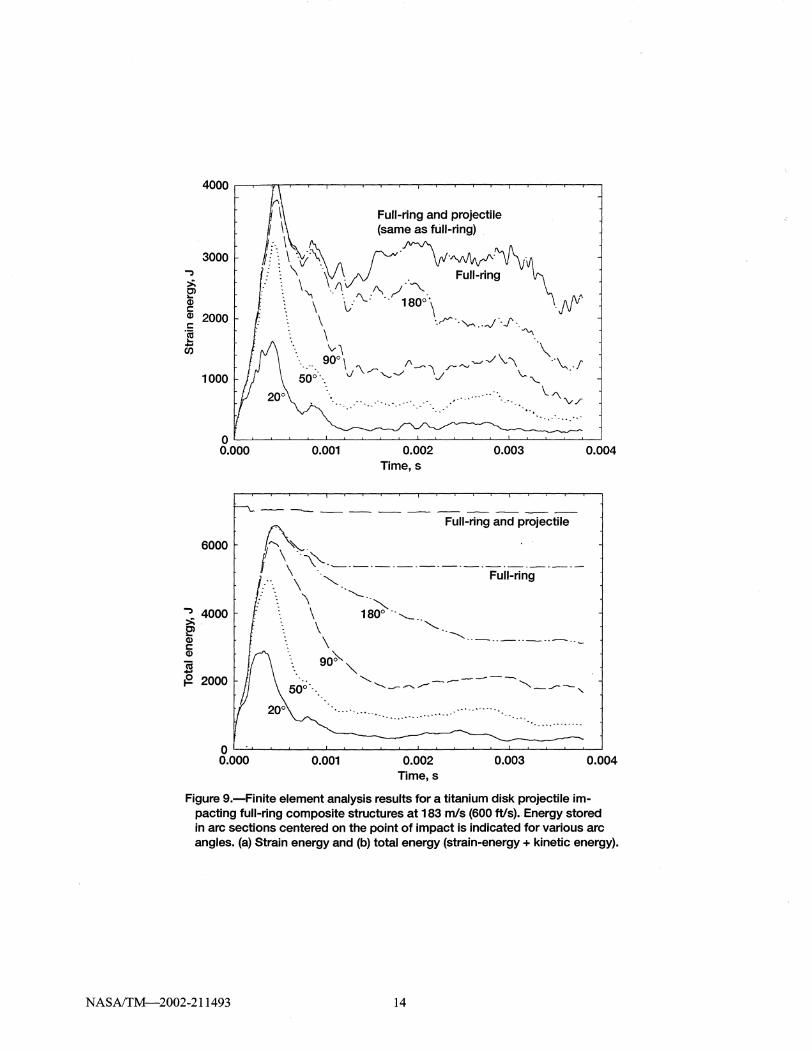
Strain energies stored in arcs of various sizes around the impact point are shown in Fig. 9(a) for the full-ring configuration. The total energy (strain energy + kinetic energy) is shown in Fig. 9(b). An additional curve showing the energy in the full-ring plus the energy in the projectile is shown in each figure. Since the projectile is modeled as a rigid body, all of its energy is in the form of kinetic energy. In Fig. 9(a) the strain energy grows to a maximum value at about 0.45 ms as the projectile comes into contact with the ring. The maximum strain energy is a little over half of the initial kinetic energy of the projectile. In Fig. 9(b) the total energy in the full-ring remains constant after about 1.0 ms because the projectile has rebounded from the ring. The maximum strain energy density in the ring is a useful parameter for preliminary design of the ring. From Fig. 9(a) it appears that the maximum strain energy density would occur at about 0.40 ms within a 50° arc. This energy density could be used in a static composite analysis to determine how close the ring is to its ultimate strength. A static analysis could also be used to suggest changes in materials, fiber architecture, or manufacturing parameters that would provide the optimum balance between cost and performance. Future efforts will focus on refining the finite element methods to examine local contact forces, including damage, and including strain rate dependent material properties. A preliminary analysis of contact forces (not shown in this paper) revealed that contact forces depend strongly on target thickness and that contact forces are much lower when the projectile can rotate about its center of mass during impact. As a result, contact forces in the flat panel test are sometimes much higher than contact forces in the full ring test, even though the mass of the projectile is much larger in the full ring test. If the objective of the flat panel test is to simulate the local damage at contact points in a full ring test, the panel thickness
NASAfTM-2002-211493 8
and impact velocity must be carefully selected. This issue needs to be further examined in order to validate the usefulness of the small panel test data.
CONCLUSIONS
Results of impact tests on 18 x 18 cm (7 x 7 in.) panels indicate that the ballistic limit of composites can approach that of metals. A protective ceramic surface layer is a promising approach for preventing fiber shear failure on the impact surface but not for limiting delamination. Transverse fiber reinforcement can be used to control delamination during impact. Use of a proposed 91 cm (36 in.) diameter full-ring subcomponent is a viable approach for testing feasibility of composite concepts at a larger scale than the small panel tests. Preliminary explicit finite element analyses suggest that small panel tests can be a cost effective way to evaluate local impact resistance of a composite at points of contact with the projectile if panel thickness and impact velocity are properly chosen. Sections of the proposed 91 cm (36 in.) fullring could be used for these small panel tests.
REFERENCES
ABAQUSI Explicit 5.8, Habbitt, Karlsson & Sorensen, Inc., 1998.
Abrate, S., "Impact on Composite Structures," pp. 132-4, Cambridge University Press, 1998.
Federal Aviation Regulations Part 33.94., U.S. Federal Aviation Administration.
Greszczuk, L.B., "Damage in Composite Materials Due to Low Velocity Impact," Impact Dynamics, Chapter 3, John Wiley & Sons, Inc., 1982, p. 93.
Lane, A.D., "Development of an Advanced Fan Blade Containment System," DOTIFAAlCT-89120, August 1989.
Mattingly, J.D., "Elements of Gas Turbine PropUlsion," pp. xlviii-xlix, McGraw-Hill, Inc., 1996.
Mines, R.A.W., Roach, A.M., and Jones,N., "High Velocity Perforation of Polymer Composite Laminates," Int. J. Impact Eng. 22, 1999,561-588.
Pereira, J.M. and Lerch, B.A., "Effects of Heat Treatment on the Ballistic Impact Properties of Inconel 718 for Jet Engine Fan Containment Applications," Int. J. Impact Eng. 25, 2001.
U.S. Department of Transportation/Federal Aviation Administration Report No. DOT/FAAlAR-97153, September 1997.
NASAlTM-2002-211493 9

Figure 1.-Glass/epoxy 38.1 cm (15") diameter half-ring and wedgeshaped titanium projectile.
Figure 2.-18 cm x 18 cm (7" x 7") glass/epoxy panels and cylindrical titanium projectile. Bottom panel had a ceramic layer under a nylon spall sheet on the front surface. Ceramic is removed to view the surface of the composite. (a) Front surface. (b) Back surface.
NASAlTM-2002-211493 lO
210
~J 0 + +
0 0 0
~ 190 ~ + 0 +
::.; -'(3
0 j 180 r + -(.)
III
.§ 170 ~ +
+ + - Not perforated 6
160 I- o Caught
* :t + Perforated Q
150 I IM7/ IM7/ AS4/ AS4/ Glass/
PR520 E-862 PR520 E-862 epoxy Fiber/resin
Figure 3.-Composite impact test data from 18 cm x 18 cm (7" x 7") flat panel tests.
300
280
260
rn E 240 ...: 'E :: 220 (.)
:;::; .!a 1a 200 [0
180
160L III
140 6 8 10 12
•
14
• S2 glass/E-761 ---t:.- Inconel 718, annealed -6- Inconel 718, heat treated
• IM7/PR520 o IM7/E-862
• AS4/PR520 o AS4/E-862
-0-- 304 stainless steel
16 18 20 22 Areal weight, kg/m2
Figure 4.-Ballistic limit for various composites and metal alloys.
NASAlTM-2002-211493 11
24

I.. Titanium disk
'--
11 cm (4.5") diameter 1.9 cm (0.75") thick
__ -- Composite ring
-- Steel fixture -- -- 2.54 cm (1") thick
Figure 5.-5.91 cm (36") diameter full-ring subcomponent test .
... "../'~~"'''' ..... ~~ . .-~..- _. - .~. -~'---''''''''''''-
/././ , ......................
. / '-."'. // "" ..
I \
/ \ , ' I \ ! \ I \ ! ,2 't
lLJ •
Figure 6.-Finite element mesh for 91 cm (36") diameter full-ring subcomponent.
t= 0.02 ms t = 0.11 ms t = 0.31 ms
t= 0.80 ms t = 1.00 ms t = 2.50 ms
Figure 7.-Deformation of 91 cm (36") full-ring subcomponent at various times after impact.
NASAlTM-2002-211493 12

0.1 ,I ~~--~~,-~~~~--.-~,-~~-,~--~~~~
0.0
E i -0.1 Q)
E Q)
16 g. -0.2 l5
-0.3
r- Quarter-ring _-----~ :i. fixed Be
~ --::.... r- Full-ring ... /
Quarter-ring ~ ... ~ ~ / r- Half-ring ...... . ~ /
free Be -~ ~ ~,;~::::-.../ free Be
~ "' ...... ~::--... /r- Half-ring "-- ""-:..: .... ~ ::--(:---... fixed Be
""'"' ,-. :---.... "-- '-. ...... :---.... ""'"' ." ...... :---...., ~ .. ,,> ... ~ .~
~ .....
(a) -0.4 LI ~. _~..L-~-L~~_~~-L----'-~_~~-L----'-~_~~--'
0.000 0.001 0.002 0.003 0.004 Time,s
150
100
~ 50 E
r- Quarter-ring .. < free Be /~.
>' -'0 0
\ ~ 0 \
-50
-100
Quarter- \ \ Half-ring ring fixed ~ .. ,.\ Full-ring _____ fixed Be -----Be .,\ , ' ---- -' .. '-- ~
\·.=~~if~~i~ijf~ee·BC·~'····.·.·····:·.·=·.:·:':;';=
0.000 0.001 0.002 0.003 0.004 Time,s
Figure 8.-Finite element analysis results for a titanium disk projectile impacting full-ring and quarter-ring composite structures at 183 m/s (600 ftls). Free and fixed boundary conditions (Be) were used for half-and quarter rings. (a) Horizontal displacement and (b) horizontal velocity of the upper point on the projectile.
NASNTM-2002-211493 13
4000 ' '"
3000 ..., :.; Cl ... (J.) c:: (J.) 2000 c:: .~ .... en
1000
!(\~ Full-ring and projectile ~ \ (same as full-ring)
it\ \ ... ~.'\ vr·V·'VIf'vvJ'·""'~·\ r.. v. vv .' \ \ \. .. Full-ring : : \ .l\ /\,/ ""\.... '" ~ . \ '\ \,..-'\..... 180°\ . \JJV
: \ .. ~ .. '-- .. -J 1·. \ \ """ .. 'v"\ \
--.. __ 90° \ f\ ~ .r- "-' '-" -J \. "\ .. "" .. f ... -,,\/'~ -J I J \,.
500·. v ~ '--. ~
f"\.v./
o tL-~~ __ ~~~ __ ~~~ __ ~~ __ ~~~ __ ~-L~ __ ~~~~
0.000
6000
..., 4000 :.; 2l (J.) c:: (J.)
]i {2 2000
o I . ,
0.001 0.002 Time,s
0.003
---- ---- ---- ---- ---- ---- ---- --- ---- ---- ----A Full-ring and projectile
l"-. "-jl\·.0-..
\ '\ ... ---.---.---.---.---.---.---.---.---.---.---.--\ ""-. Full-ring
\ "- "-.. \ 180° .. \ '--. .............
\ -----. .- .. _. --- .. -90;;""
"- '-.. ----~ ............ _ ............ .,.,--- " _J""'"'-, 50°-· ..
20°\ ........ _ ..............
0.004
0.000 0.001 0.002 0.003 0.004 Time,s
Figure 9.-Finite element analysis results for a titanium disk projectile impacting full-ring composite structures at 183 mls (600 ftls). Energy stored in arc sections centered on the point of impact is indicated for various arc angles. (a) Strain energy and (b) total energy (strain-energy + kinetic energy).
NASAlTM---2002-211493 14

REPORT DOCUMENTATION PAGE Form Approved
OMB No. 0704-0188
Public reporting burden for this collection of information is estimated to average 1 hour per response, including the time for reviewing instructions, searching existing data sources, gathering and maintaining the data needed, and completing and reviewing the collection of information. Send comments regarding this burden estimate or any other aspect of this collection of information, including suggestions for reducing this burden, to Washington Headquarters Services, Directorate for Information Operations and Reports, 1215 Jefferson Davis Highway, Suite 1204, Arlington, VA 22202-4302, and to the Office of Management and Budget, Paperwork Reduction Project (0704-0188), Washington, DC 20503.
1. AGENCY USE ONLY (Leave blank) 12. REPORT DATE 13_ REPORT TYPE AND DATES COVERED
April 2002 Technical Memorandum 4. TITLE AND SUBTITLE 5. FUNDING NUMBERS
Impact Testing and Analysis of Composites for Aircraft Engine Fan Cases
6. AUTHOR(S) ~-708-24-13-O0
Gary D. Roberts, Duane M. Revilock, Wieslaw K Binienda, Walter Z_ Nie, S. Ben Mackenzie and Kevin B. Todd
7. PERFORMING ORGANIZATION NAME(S) AND ADDRESS(ES) 8. PERFORMING ORGANIZATION REPORT NUMBER
National Aeronautics and Space Administration John H. Glenn Research Center at Lewis Field E-13206 Cleveland, Ohio 44135-3191
9. SPONSORINGIMONITORING AGENCY NAME(S) AND ADDRESS(ES) 10. SPONSORINGIMONITORING AGENCY REPORT NUMBER
National Aeronautics and Space Administration Washington, DC 20546-0001 NASA TM-2002-211493
11. SUPPLEMENTARY NOTES
Gary D_ Roberts and Duane M. Revilock, NASA Glenn Research Center; Wieslaw K Binienda and Walter Z. Nie, University of Akron, Department of Civil Engineering, Akron, Ohio 44325-3905; S. Ben Mackenzie and Kevin B. Todd, Saint-Gobain Performance Plastics, 335 N. Diamond Street, Ravenna, Ohio 44266. Responsible person, Gary D. Roberts, organization code 5150, 216-433-3244.
12a. DISTRIBUTION/AVAILABILITY STATEMENT 12b. DISTRIBUTION CODE
Unclassified -Unlimited Subject Category: 07 Distribution: Nonstandard
Available electronically at ht1;p:/lgltrs.grc.na~a.gov/GLTRS
This publication is available from the NASA Center for AeroSpace Infonnation, 301-621-0390. 13. ABSTRACT (Maximum 200 words)
The fan case in a jet engine is a heavy structure because of its size and because of the requirement that it contain a blade released during engine operation. Composite materials offer the potential for reducing the weight of the case. Efficient design, test, and analysis methods are needed to efficiently evaluate the large number of potential composite materials and design concepts. The type of damage expected in a composite case under blade-out conditions was evaluated using a subscale test in which a glass/epoxy composite half-ring target was impacted with a wedge-shaped titanium projectile. Fiber shearing occurred near points of contact between the projectile and target. Delamination and tearing occurred on a larger scale. These damage modes were reproduced in a simpler test in which flat glass/epoxy composites were impacted with a blunt cylindrical projectile. A surface layer of ceramic eliminated fiber shear fracture but did not reduce delamina-tion. Tests on 3D woven carbon/epoxy composites indicated that transverse reinforcement is effective in reducing delamination. A 91 cm (36 in.) diameter full-ring subcomponent was proposed for larger scale testing ofthese and other composite concepts. Explicit, transient, finite element analyses indicated that a full-ring test is needed to simulate complete impact dynamics, but simpler tests using smaller ring sections are adequate when evaluation of initial impact damage is the primary concern.
14. SUBJECT TERMS 15. NUMBER OF PAGES
Jet engines; Containment; Fan blades; Carbon-epoxy composites; Glass-epoxy composites; 20 16. PRICE CODE Woven composites; Composite structures; Impact tests; Ballistics
17. SECURITY CLASSIFICATION 18. SECURITY CLASSIFICATION 19. SECURITY CLASSIFICATION OF REPORT OF THIS PAGE OF ABSTRACT
Unclassified Unclassified Unclassified --------- ---_ .. _--------- _ .. - ------- -- -- -
NSN 7540-01-280-5500
20. LIMITATION OF ABSTRACT
Standard Form 298 (Rev. 2-89) Prescribed by ANSI Std. Z39-18 298-102