
IMPACT OF MICRO GROOVES AND WINGLETS ON THE …
10
American Journal of Innovative Research and Applied Sciences. ISSN 2429-5396 I www.american-jiras.com 266 | Wajahat Hassan * 1 | and | Muhammad Naeem 1 | 1. Institute of Space Technology | Aeronautics & Astronautics | Islamabad | Pakistan | | Received | 19 September 2018 | | Accepted 02 November | | Published 15 November 2018 | | ID Article | Wajahat-ManuscriptRef.1-ajira201018 | Abstract Background: The Centrifugal pump efficiency is prompted with the aid of secondary flows like a tip leakage and boundary layer separation. The main goal is to analyze, integrate influences of micro-grooves and winglets at the overall performance of the centrifugal pump. Method: Four semi-open impeller geometries are made in keeping with following sequences-the smooth impeller having a smooth hub, winglet impeller having a smooth hub, the smooth impeller having micro grooves on the hub, and the impeller having winglet and micro grooves on the hub. Turbo Grid is used to generate hexahedral meshing in enormously oriented style. The viscous model used is SST (Shear Stress Transport). CFD is employed in a steady state to numerically examine the flow characteristic according to pressure, velocity, and shaft power. Result: After simulation, it is noticed that winglets and micro-grooves create negative effects on the pump head, static pressure and total pressure. However, on the other hand, total efficiency and static efficiency in last three cases are increased as compared to case-1. Conclusion: Shaft power of pump is decreased by making winglets impellers and micro grooves on the hub of the impeller. It depicts that the pump is operating at less power. Keywords: Trailing Edge, Vortex, Impeller, Efficiency, SST. 1. INTRODUCTION A Pump is a device used to transfer energy to an incompressible fluid (constant density) to flow in the pipeline. In this definition, we can see two phenomena’s are occurred: first, energy is being imparted to a liquid in the form of velocity. Second, energy is converted into a steady flow. Performance parameters of the centrifugal pump are head and efficiency. The main parts that are responsible, behind the working phenomenon of the centrifugal pump are as under Impeller (Rotating component) Casing (Stationary component) Pump shaft Impellers are the rotating components of the pump which accelerate fluid from the center of rotation. This accelerated fluid converts into velocity and then into pressure after coinciding with the pump casing. Casing is the component that changes all of the energy created by the spinning impeller into a controlled and pressurized flow [1]. In turbo machinery design flow, describe in fixed (absolute) coordinates and rotating (relative) reference frame. In absolute system a point on a rotating disk is circular and in the relative reference frame point on a rotating disk is stationary [2]. The electric motor and mechanical machines are practiced to rotate the pump shaft for pumping purposes. Pump shaft is a central part of the rotor that transmits torque to the impeller. Pumps are classified into two types; Dynamic Pump and Volumetric Pump. According to the law of the turbomachinery, the dynamic pump works under the law of conservation of angular momentum. In a volumetric pump, a fixed amount of fluid is propelled from the chamber to the discharge pipe. A centrifugal pump is a machine from the family of a Rota dynamic machine consists of a stationary (Casing) and rotating element (impeller) [3]. During operation, it is filled with water and impeller rotates in a clockwise direction to increase the velocity at the exit of vanes. This phenomenon decreases the outward flow and pressure in the impeller eye, allowing the liquid to enter into the pump and before leaving the pump discharge velocity converts into pressure. To achieve higher efficiency, it is important to transfer energy from impeller to liquid in an efficient manner. High efficiency can be achieved through the design of impeller. ORIGINAL ARTICLE IMPACT OF MICRO GROOVES AND WINGLETS ON THE PERFORMANCE OF CENTRIFUGAL PUMP *Corresponding author & Author Copyright © 2018: | Wajahat Hassan |. All Rights Reserved. All articles published in American Journal of Innovative Research and Applied Sciences are the property of Atlantic Center Research Sciences, and is protected by copyright laws CC-BY. See: http://creativecommons.org/licenses/by-nc/4.0/.
Transcript of IMPACT OF MICRO GROOVES AND WINGLETS ON THE …

American Journal of Innovative Research and Applied Sciences. ISSN 2429-5396 I www.american-jiras.com
266
| Wajahat Hassan *1 | and | Muhammad Naeem 1 |
1. Institute of Space Technology | Aeronautics & Astronautics | Islamabad | Pakistan |
| Received | 19 September 2018 | | Accepted 02 November | | Published 15 November 2018 | | ID Article | Wajahat-ManuscriptRef.1-ajira201018 |
Abstract
Background: The Centrifugal pump efficiency is prompted with the aid of secondary flows like a tip leakage and boundary layer separation. The main goal is to analyze, integrate influences of micro-grooves and winglets at the overall performance of the centrifugal pump. Method: Four semi-open impeller geometries are made in keeping with following sequences-the smooth impeller having a smooth hub, winglet impeller having a smooth hub, the smooth impeller having micro grooves on the hub, and the impeller having winglet and micro grooves on the hub. Turbo Grid is used to generate hexahedral meshing in enormously oriented style. The viscous model used is SST (Shear Stress Transport). CFD is employed in a steady state to numerically examine the flow characteristic according to pressure, velocity, and shaft power. Result: After simulation, it is noticed that winglets and micro-grooves create negative effects on the pump head, static pressure and total pressure. However, on the other hand, total efficiency and static efficiency in last three cases are increased as compared to case-1. Conclusion: Shaft power of pump is decreased by making winglets impellers and micro grooves on the hub of the impeller. It depicts that the pump is operating at less power. Keywords: Trailing Edge, Vortex, Impeller, Efficiency, SST.
1. INTRODUCTION A Pump is a device used to transfer energy to an incompressible fluid (constant density) to flow in the pipeline. In this
definition, we can see two phenomena’s are occurred: first, energy is being imparted to a liquid in the form of velocity.
Second, energy is converted into a steady flow. Performance parameters of the centrifugal pump are head and efficiency.
The main parts that are responsible, behind the working phenomenon of the centrifugal pump are as under
Impeller (Rotating component)
Casing (Stationary component)
Pump shaft
Impellers are the rotating components of the pump which accelerate fluid from the center of rotation. This accelerated
fluid converts into velocity and then into pressure after coinciding with the pump casing. Casing is the component that
changes all of the energy created by the spinning impeller into a controlled and pressurized flow [1]. In turbo machinery design flow, describe in fixed (absolute) coordinates and rotating (relative) reference frame. In absolute
system a point on a rotating disk is circular and in the relative reference frame point on a rotating disk is stationary [2]. The electric motor and mechanical machines are practiced to rotate the pump shaft for pumping purposes. Pump shaft
is a central part of the rotor that transmits torque to the impeller. Pumps are classified into two types; Dynamic Pump
and Volumetric Pump. According to the law of the turbomachinery, the dynamic pump works under the law of conservation of angular momentum. In a volumetric pump, a fixed amount of fluid is propelled from the chamber to the
discharge pipe. A centrifugal pump is a machine from the family of a Rota dynamic machine consists of a stationary (Casing) and
rotating element (impeller) [3].
During operation, it is filled with water and impeller rotates in a clockwise direction to increase the velocity at the exit of
vanes. This phenomenon decreases the outward flow and pressure in the impeller eye, allowing the liquid to enter into the pump and before leaving the pump discharge velocity converts into pressure. To achieve higher efficiency, it is
important to transfer energy from impeller to liquid in an efficient manner. High efficiency can be achieved through the design of impeller.
ORIGINAL ARTICLE
IMPACT OF MICRO GROOVES AND WINGLETS ON THE
PERFORMANCE OF CENTRIFUGAL PUMP
*Corresponding author & Author Copyright © 2018: | Wajahat Hassan |. All Rights Reserved. All articles published in American Journal of Innovative Research and Applied Sciences are the property of Atlantic Center Research Sciences, and is protected by copyright laws CC-BY. See: http://creativecommons.org/licenses/by-nc/4.0/.

American Journal of Innovative Research and Applied Sciences. ISSN 2429-5396 I www.american-jiras.com
267
The micro groove is a narrow and long cut on the surface of the impeller hub that start from the base of the leading
edge to the trailing edge of the impeller. In fact, micro-grooves are practiced to raise the capacity of the impeller to transmit power to liquid [4]. The winglet is used to control tip leakage flow at the trailing edge of the impeller. The
winglet is an additional tip surface added with the impeller trailing edge, which is made to control vortex on the tip of the impeller. Experimental works especially dedicated to the analysis of tip clearance effects on semi-open impellers
show that utmost of the performance of the machines deteriorates as per tip clearance increases [5]. The phenomena behind performance reduction due to tip clearance is a tip leakage flow that partially mixes with the core flow.
2. Literature review
Janusz and Marcin [4] are focused on the influence of micro grooves on the parameter of the centrifugal pump impeller. The Modified micro-grooved impeller is designed to reduce the hydraulic losses. At extremely low speed, the impact of
micro grooves on the efficiency of the centrifugal pump was studied. Two geometries were designed in Ansys software first one with the smooth impeller and second having micro grooves. In the results section, distribution of velocity field
and the pressure control section were compared to each other. Whereas examining velocity, it was noticed that there were more irregularities in the micro-grooved impeller closer to the boundary wall of the impeller as compare to the
smooth impeller. More dynamic depression was seen on the inter-blade channel of the micro-grooved impeller.
Boitel, Fedala and Myon [5], briefly studied tip clearance effects on the performance of centrifugal pumps at different
RPM. Four pumps with different tip clearance were analyzed at a specified speed that varies from 8 to 50 SI Units. CFD based on steady-state and the k-omega SST turbulence model was employed to examine geometric behavior.
Numerical results show that head, efficiency, and power were increased after tip clearance was reduced within the
whole flow range. The resulting axial thrust on the impeller tip clearance was also very sensitive.
Ibrahim and Mohamad [6] studied high-speed C.F Compressor having different blade tip geometries. This study was for the compressible flow with 3D simulation. For changing the tip geometry of an impeller nova parameterization method
was employed. In this method, flat tip blade and the main blade winglet were examined. The compressor performance
and operational stability at the lower flow rate were increased significantly by using tip geometry. By using winglets, pressure ratio and surge margin were significantly improved as compared to the simple blade. By unloading tip suction,
aerodynamic losses were recovered.
3. Numerical method
The Reynolds Averaged Navier-Stokes (RANS) equations of steady incompressible flow are practiced for the calculation of polar coordinates and rotating with the impeller system of references [7]. The basic conservation equations are
stated in vectored form, in these expressions, bold alphabets and symbols represent vector forms: Continuity: (3.1)
Momentum:
(3.2)
τij = 2µ ⋅ sij - ρ⋅ wi′ ⋅ w′j (3.3)
4. Geometry parameterization
The geometry details of the centrifugal flow impeller are shown below in Table 4.1.
Table 4.1: Pump Impeller dimensions. Rotational Speed 1450 RPM Blade 6 Volume flow rate 280 m³/hr Density 1000 kg/m³
Head rise 20 m Inlet flow angle 90° Merid velocity ration 1.1 Impeller inlet Diameter (D₁) 83.1 mm Impeller outlet Diameter (D₂) 271.9 mm
Blade inlet angle (β₁) 29.37ᵒ Blade outlet angle (β₂) 13.11ᵒ
American Journal of Innovative Research and Applied Sciences. ISSN 2429-5396 I www.american-jiras.com
268
Rotational speed can be quantified as the number of revolutions a rotating system makes within a defined period of
time. The unit used for pump rotational speed is normally given in min–1 (rpm). The volume flow rate of the fluid is the volume of fluid passes per unit time, which controls the delivery volumetric flow rate of the pump. The pump head
setting regulates the total dynamic head rise of the pump according to the design point of view. The head rise is equal to the sum of velocity head rise and static head rise. The centrifugal pump having a smaller inlet gives a larger inlet
velocity head. Inlet flow angle is employed to regulate flow on the impeller leading edge, measured according to the tangential direction [8]. Meridional velocity ratio describes a linear velocity profile from the hub to shroud at the leading
edge. Value 1.1 indicates a higher meridional velocity at the shroud rather than at the hub. A value of less than 1
indicates a higher meridional velocity at the hub as compared to the shroud. A value of 1 indicates a uniform meridional velocity distribution.
Case: 1
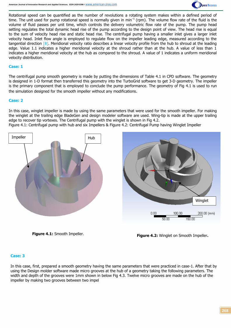
The centrifugal pump smooth geometry is made by putting the dimensions of Table 4.1 in CPD software. The geometry is designed in 1-D format then transferred this geometry into the TurboGrid software to get 3-D geometry. The impeller
is the primary component that is employed to conclude the pump performance. The geometry of Fig 4.1 is used to run
the simulation designed for the smooth impeller without any modifications.
Case: 2
In this case, winglet impeller is made by using the same parameters that were used for the smooth impeller. For making the winglet at the trailing edge BladeGen and design modeler software are used. Wing-tip is made at the upper trailing
edge to recover tip vortexes. The Centrifugal pump with the winglet is shown in Fig 4.2.
Figure 4.1: Centrifugal pump with hub and six Impellers & Figure 4.2: Centrifugal Pump having Winglet Impeller
Figure 4.1: Smooth Impeller.
Figure 4.2: Winglet on Smooth Impeller.
Case: 3
In this case, first, prepared a smooth geometry having the same parameters that were practiced in case-1. After that by
using the Design molder software made micro grooves at the hub of a geometry taking the following parameters. The width and depth of the grooves were 1mm shown in below Fig 4.3. Twelve micro grooves are made on the hub of the
impeller by making two grooves between two impel
Hub Impeller
Winglet

American Journal of Innovative Research and Applied Sciences. ISSN 2429-5396 I www.american-jiras.com
269
Figure 4.3: Micro Grooves on the Smooth Impeller
Hub.
Figure 4.4: Centrifugal Pump with Winglet and
Micro-Grooves.
Case: 4
Case-4 has a geometry having the combined influence of both micro grooves and winglets. First, took a geometry from
case-2 (winglet impeller geometry) then made grooves on the hub of this geometry of the same parameters that were used in a case no.3. Fig 4.4 shows the geometry of centrifugal pump with winglet and micro grooves.
5. Solver settings Simulations of these four geometries are performed to realize the impact of efficiency (%) and head (m) on the
performance of a centrifugal pump. There are following steps to approach results:
5.1 Mesh Generation All real-life phenomena occur in a continuous domain. However, it is not possible to solve fluid flow equations at an infinite number of points in a continuous domain. A continuous domain is changed into a discrete domain by a method
called meshing. Fluid flow equations are solved at these finite points. In these cases, the TurboGrid tool is employed to generate high-quality hexahedral meshing in highly oriented manners [9]. Details of the mesh sizing are given below in
Table 5.1.
Table 5.1: Details of the Mesh Size.
Method Global size factor
Size factor 1.2
Global size factor in Ansys Turbo Grid is employed to automatically adjust the mesh size factor to achieve the desired
mesh size. The size factor setting is practiced to increase or decrease the resolution of mesh size [10]. Change in the mesh sizing is not linear. The global size factor will remain fixed however, you change boundary layer refinement, local
edge, refinement or spanwise mesh size. Table 5.2 explain boundary layer refinement control conditions. In this
context, BL is represented by the set of topology blocks: along the pressure and suction side of the blade. The thickness of the boundary layer varies along the blade profile.
Table 5.2: Boundary layer refinement control.
Method Proportional to Mesh
Size
Parameter (Factor Base) 0.0
Parameter (Factor Ratio) 2.0
Near-wall element size specification Absolute
Groove

American Journal of Innovative Research and Applied Sciences. ISSN 2429-5396 I www.american-jiras.com
270
By using Turbo Grid got results of cases, (1, 2, 3, 4) correspondingly given below in figures 5.1, 5.2, 5.3, and 5.4.
Figure 5.1: Smooth Impeller Mesh. Figure 5.2: Winglet Impeller Mesh.
Figure 5.3: Smooth Impeller having Grooved Mesh. Figure 5.4: Winglet Impeller having Grooves.
5.2 CFX Setup
After the meshing process, the next step is to transfer meshed geometry into the turbo-specific setup called CFX setup that is practiced for the turbomachinery simulation. First, select a machine type to define the axis of rotation and then
set the rotation speed.
Table 5.3: Basic setting of CFX setup.
Machine type Pump
Rotational speed 1450 RPM
Analysis type Steady State
A physical definition panel is shown below in Table 5.4, takes water as a working fluid and reference pressure is zero
(atm). The reference pressure, present to an absolute pressure that is helpful to take all other pressure values.

American Journal of Innovative Research and Applied Sciences. ISSN 2429-5396 I www.american-jiras.com
271
Table 5.4: Physical definition. Working Fluid Water
Reference pressure 0 (atm)
Heat transfer None
Turbulence Shear Stress Transport
Physical time scale 1e-2 s
For forecasting attachments and slightly detached flow, RANS model is considered. But in large separation regions, RANS model does not work properly (fails) to predict the correct turbulence stress level. So under such conditions,
Shear Stress Transport model (SST) is used to predict separation with decent accuracy [8].
5.3 Boundary Conditions
The boundary condition is the physical condition at the periphery of the model that restricts the software according to
your choice. In this case, after finishing the CFX-setup process periodic interface and standard boundary conditions are defined automatically: but according to flow requirements, this condition can be changed. In the boundaries interface
selection, R1 Hub is checked for all the cases that are shown in figures 5.5, 5.6, 5.7 and 5.8. Table 5.5 shown below
gives details of the boundary wall and wall interface on flow:
Table 5.5: Boundary Interface at R1 Hub. Boundary Type Wall
Wall influence on flow, Caption No slip wall
The wall boundary conditions are assured that fluid cannot enter or exit from any path rather than the specified
channel. The no-slip condition is the most common type of wall boundary condition in which fluid sticks to the wall. In this condition, if the wall is not stationary, then the fluid will also travel along the wall with the same velocity.
Figure 5.5: Case (1) Smooth Impeller R1 Hub Flow. Figure 5.6: Case (2) Winglet Impeller R1 Hub Flow
So the no-slip wall is specified for the stationary or moving wall fluid velocity and the boundary reference frame is relative to this motion. The green area in Fig 5.5 represents the hub of the impeller.
Inlet
Outlet
R1 Hub

American Journal of Innovative Research and Applied Sciences. ISSN 2429-5396 I www.american-jiras.com
272
Figure 5.7: Case (3) Figure 5.8: Case (4)
Boundary R1 Hub outlet created; this boundary represents to the stationary wall section on the housing of the hub.
Table 5.6: Boundary Interface Selected at R1 Hub, Outlet.
Boundary type Wall
Wall influence on the flow Counter-rotating wall
6. RESULTS AND DISCUSSIONS
6.1 Velocity Streamlines at Blade TE
Fluid flow simulation is employed to visualize a line traveled by a massless particle or a path traced out by a massless partial, released from one or more regions. Velocity streamlines show the direction of the fluid element with respect to
time at any point. The results of velocity streamlines are below in Fig 6.1 after simulation of a case-1. Due to tip leakage at the trailing edge, vortexes are formed that are shown at the upper corner of trailing edge. These vortexes are
responsible to decrease velocity at the trailing edge of the impeller. Disturbed flow is the main factor to decrease velocity: when this flow enters again and again into the core flow create blockage and recirculation (vortexes). Due to
this blockage, priming phenomena of the pump can be affected.
Figure 6.1: Velocity Stream Lines at Blade Trailing
Edge (Case-1) Figure 6.2: Velocity Streamlines at Blade Trailing
Edge (Case-2)
Blue line vortexes are clearly shown on both impellers trailing edge upper corner in Fig 6.1. LE cut velocity is 4.8457
[m⋅s−1] and TE cut velocity is 11.5225 [m⋅s−1]. Along the streamwise direction with-in, the impeller passages relative
velocity is increased progressively. The ‘streamlines’ velocity at the upper trailing edge of the impeller is 14 [m⋅s−1].
While analyzing velocity streamlines it is noticed that closer to the boundary wall there are more irregularities.
Outlet
Inlet
R1 Hub
Trailing edge vortex

American Journal of Innovative Research and Applied Sciences. ISSN 2429-5396 I www.american-jiras.com
273
Case-2 in which winglets are used shown in Fig 6.2. In this case tried to recover tip leakage flow by using winglet
impeller. The LE cut velocity is 4.6322 [m⋅s−1] and the TE cut velocity is 11.2609 [m⋅s−1]. Velocity at the upper trailing
edge is reached to 15.7500 [m⋅s−1]. Because of tip leakage recovery, low-speed streamlines and vortexes at the trailing
edge are recovered and flow blockage at the upper corner of the trailing edge is reduced. Therefore, using winglet tip stability is improved as compared to the smooth impeller.
CFD is employed to get results of a geometry having micro grooves only: results of streamline velocity are shown below
in Fig 6.3. The streamline velocity at the upper trailing edge of the impeller reached to 14.7625 [m⋅s−1]. Streamline
velocity is increased in this situation as compared to case-1 because tip leakage recovery is controlled. The backward
flow owing to tip vortexes correspondingly reduced. LE cut velocity is 4.8858 [m⋅s−1] and TE cut velocity is 11.4009
[m⋅s−1]. The main factor that contributes to recover vortexes, in this case, is a specified channel of the fluid particle.
Figure 6.3: Velocity Streamlines at Blade Trailing Edge (Case-3).
Figure 6.4: Velocity Streamlines at Blade Trailing Edge (Case-4).
Micro-grooves with combined winglet are used in case-4. After simulation results of streamlining velocity are shown
below in Fig 6.4. In this case, tip leakage recovery is more than any other case. The LE cut velocity is 4.6775 [m⋅s−1]
and the TE cut velocity is 11.2027 [m⋅s−1]. The core flow is less disturbed by vortexes so the pressure is increased.
Streamline velocity reached to 16.6550 [m⋅s−1] at the trailing edge upper corner. In this case, efficiency also increases
as compared to other three cases.
6.2 Performance Results for the Pump Impeller
The performance of an impeller is depended on the mass flow rate, head, and efficiency of the pump. The results of four cases are given below in figure 6.5. These results are compared with each other to know the trends of pump
performance.
In case-1, when the mass flow rate was 77.8 [kg/s] then head 21.831 [m] and efficiency was 94.3965 %. After that by increasing the mass flow rate to 100 [kg/s], head decreased and reached at 18.753 [kg/s], however, efficiency is
increased slightly and approach to 95.449 %. When the mass flow rate was 200 [kg/s], efficiency and head reached
at 71.9604 %, 3.8155 [m] convectively. In this case, static efficiency is 79.7551 % and total efficiency 94.3952 %. The Shaft power required to run the impeller is 17645 [W]. These results depict that at the actual-designed mass flow
rate (77.8 kg/s) pump got the highest value of head. When we increase the mass flow rate, the head starts decreasing because the flow rate at the outlet of the pump starts decreasing. By increasing mass flow rate efficiency
start increasing slightly, and then start decreasing gradually by increasing the mass flow rate above 100 (kg/s). These
results show that as we increase mass flow rate velocity at the outlet of impeller reduce because of the reverse flow disturbance increase. It is also noticed that shaft horsepower is greater than other three cases, so efficiency is lower.
In case-2 according to our operating conditions of mass flow rate, that was 77.8 [kg/s] at this value efficiency is
increased and reached to 95.174 %, the increment of efficiency is 0.779 %. The static efficiency, in this case, is 80.9918 % it concludes that static efficiency is increased with 1.2367 % increment. Winglet generates a positive
impact on efficiency and shaft power. Tip leakage flow is reduced that was disturbing core flow. By increasing the
mass flow rate to 100 [kg/s] head is decreased and reached at 18.169 [m], however, efficiency is slightly increased in this case that is 95.564 %. When mass flow was 200 [kg/s] efficiency and head reached at 64.154 %, 2.7727 [m]

American Journal of Innovative Research and Applied Sciences. ISSN 2429-5396 I www.american-jiras.com
274
convectively. The Shaft power required to run this impeller is 17186.000 [W] that is 459 [W] lesser than Case-1. The
main factor that contributes to increasing efficiency is shaft horsepower that is lesser in this case.
Figure 6.5: Performance Results for the Pump Impeller.
In case-3, according to our operating conditions of mass flow, that was 77.8 [kg/s] at this value efficiency is 95.174 %,
the increment of efficiency is 0.219 %. The static efficiency, in this case, is 80.1855% it means static efficiency is increased with 0.4304 % increment. By increasing the mass flow rate to 100[kg/s] head decreased and reached 18.488
[kg/s], however, efficiency is slightly increased in this case that is 95.557 %. When the mass flow rate was 200 [kg/s], efficiency and the head reached to 64.866 %, and 2.8655 [m] convectively. The Shaft power required to run this
impeller is 17466.000 [W], that’s mean 179 [W] lesser shaft power is required to run the pump in this case.
Case-4 in which mass flow rate was 77.8 [kg/s], the results of head and efficiency are 21.33 and 95.241 %
respectively. The increment in the total efficiency as compare to case-1 is 0.846 % and static efficiency, in this case, is 81.1825 %. It depicts that static efficiency is increased with the increment of 1.4274 %. By increasing the mass flow
rate to 100 [kg/s]: head decreased and reached 18.118 [m], but efficiency is slightly increased and reached 95.583 %. When the mass flow rate, was 200 [kg/s] efficiency and head approach to 63.353 % and 2.6617 [m] convectively.
Shaft power required to run this impeller is 17089.000 [W], it depicts that 556 [W] lesser shaft power is required to run the pump. Highest efficiency is achieved by combined treatment of winglet and micro grooves.
63
63,75
64,5
65,25
66
66,75
67,5
68,25
69
69,75
70,5
71,25
72
72,75
73,5
74,25
75
75,75
76,5
77,25
78
78,75
79,5
80,25
81
81,75
82,5
83,25
84
84,75
85,5
86,25
87
87,75
88,5
89,25
90
90,75
91,5
92,25
93
93,75
94,5
95,25
96
96,75
0
0,5
1
1,5
2
2,5
3
3,5
4
4,5
5
5,5
6
6,5
7
7,5
8
8,5
9
9,5
10
10,5
11
11,5
12
12,5
13
13,5
14
14,5
15
15,5
16
16,5
17
17,5
18
18,5
19
19,5
20
20,5
21
21,5
22
22,5
23
60 70 80 90 100 110 120 130 140 150 160 170 180 190 200 210
Hea
d (
m)
Mass flow rate (kg/s)
Head (1) Head(2) Head(3)
Head(4) Case(1) Case(2)
Case(3) Case(4)
Eff
icie
ncy
(%
)

American Journal of Innovative Research and Applied Sciences. ISSN 2429-5396 I www.american-jiras.com
275
7. CONCLUSION Semi-open centrifugal pump impellers are modeled in BladeGen and Design modeler software. CFX solver is used for
simulation of these models, then analyzed with the help of CFD-Post results. The pump performance results are plotted in the form of pressure contour, velocity, total efficiency, shaft power and the streamline variation of four different
geometries. The micro grooves, winglet and combine geometry of both have a great effect on the centrifugal pump
performance.
CFD results clearly shown that total efficiency is increased in case-2, case-3 and case-4 as compared to case-1
respectively 0.78 %, 0.22 %, 0.85 %. The Static efficiency is, also increased according to following sequence 1.24 %, 0.4307 %, 1.44 %.
The impact of velocity streamlines the flow structure are examined from the visualization of flow patterns in
the impellers passages, from the leading edge plane to the trailing edge plane. Tip leakage recovery is
improved in case-2, 3 and 4 gradually as compare to Case-1.
Head is reduced by changing the geometry parameters in Case-2, Case -3, Case-4, accordingly 0.39 m, 0.17
m, 0.49 m.
These modified models, create remarkable effects on the shaft power that is reduced to 458.8 (W), 280.2 (W)
and 556 (W) consecutively as compared to Case-1.
8. REFERENCES
1. Jon Penland: What is a centrifugal pump. Available on: https://www.introtopumps.com/pumps-101/what-is-a-centrifugal-pump.
2. Johann Friedrich Gulich: Centrifugal Pumps. 2008 vol. 1. pp. 2-6. Available on: http://www.academia.edu/19260955/CENTRIFUGAL_PUMPS.
3. Mr. Nilesh Nemgonda Patil. A review paper on the development of impeller of the centrifugal pump using computational fluid dynamics. International Journal of
engineering sciences & research technology. Nilesh, September 2015; 4(9): 29-31. Available on: http://www.ijesrt.com/issues%20pdf%20file/Archives-
2015/September-
2015/7_A%20REVIEW%20PAPER%20ON%20DEVELOPMENT%20OF%20IMPELLER%20OF%20CENTRIFUGAL%20PUMP%20USING%20COMPUTATI
ONAL%20FLUID%20DYNAMICS.pdf.
4. Janusz Skrzypacz., Marcin Bieganowski. The influence of microgrooves on the parameters of the centrifugal pump impeller. International Journal of Mechanical
Sciences. August 2018; 144: 827-835. Available on: https://kundoc.com/pdf-the-influence-of-micro-grooves-on-the-parameters-of-the-centrifugal-pump-
impelle.html.
5. G Boitel., D Fedala., and N Myon. Tip clearance effects on loads and performances of semi-open impeller centrifugal pumps at different specific speeds. 28th
IAHR Symposium on Hydraulic Machinery and Systems, (IAHR2016). Available on:
https://www.researchgate.net/publication/311619892_Tip_clearance_effects_on_loads_and_performances_of_semi
open_impeller_centrifugal_pumps_at_different_specific_speeds.
6. Ibrahim Shahina., Mohamad Alqaradwai. Effect of blade tip geometry on centrifugal compressor performance and stability. Journal of Engineering and Applied
Sciences. 2016; 11(12): 2773-2778. Available on: http://docsdrive.com/pdfs/medwelljournals/jeasci/2016/2769-2774.pdf.
7. John. S. Anagnostopoulos. Numerical Calculation of the Flow in a Centrifugal Pump Impeller Using Cartesian Grid. Proceedings of the second, WSEAS Int.
Conference on Applied and Theoretical Mechanics, Venice, Italy, November 20-22, 2006. Available on: http://www.wseas.us/e-
library/conferences/2006venice/papers/539-661.pdf.
8. ANSYS Turbo System User Guide: Release 15.0. Available on: https://www.academia.edu/9518485/ANSYS_TurboSystem_Users_Guide.
9. Jeff Erickson. Theoretical Advances in Hexahedral Mesh Generation” University of Illinois, Urbana-Champaign.2010, 16-11. Available on:
http://jeffe.cs.illinois.edu/pubs/talks/hexmesh-survey-socg.pdf.
10. The Mesh Data Objects, Release 16.2 page: 2-10. Available on: https://www.sharcnet.ca/Software/Ansys/17.0/en-us/help/tg_user/tgANSYMeshMesh.html.
Cite this article: Wajahat Hassan, and Muhammad Naeem. IMPACT OF MICRO GROOVES AND WINGLETS ON THE PERFORMANCE OF CENTRIFUGAL PUMP. Am. J. innov. res. appl. sci. 2018; 7(5): 266-275.
This is an Open Access article distributed in accordance with the Creative Commons Attribution Non
Commercial (CC BY-NC 4.0) license, which permits others to distribute, remix, adapt, build upon this work
non-commercially, and license their derivative works on different terms, provided the original work is
properly cited and the use is non-commercial. See: http://creativecommons.org/licenses/by-nc/4.0/