IMPACT OF FORGING PRESSURE ON MICROSTRUCTURE …
7
IMPACT OF FORGING PRESSURE ON MICROSTRUCTURE BEHAVIOR OF FRICTION WELDED MS / SS DISSIMILAR STEEL JOINTS 1 Rajesh. A*, 2 Ashokavarthanan. P, 3 Sanjay Kanna. K. S, 4 Saravana Kumar. S, 5 Vinoth. M, 6 Sivasakathi.C Associate Professor , 2 Professor & Head, 3-6 U. G Scholar, 1-6 Department of Mechanical Engineering, Sri Krishna College of Engineering and Technology, Coimbatore-641008 ABSTRACT Mild steel and stainless steel (304 L) were used in various applications, including shipbuilding, boilers, aircraft, and automobiles, due to low cost and machinability. This alloy is welded using the fusion welding technique. Furthermore, the strength of welded joints has exceeded 60% of the strength of the base materials. When dissimilar steels are joined, however, maintaining a high-quality weld is difficult. As a result, careful consideration must be given to the electrode, filler wire, and perhaps other process parameters such as current, voltage, and shielding gas. Friction welding (FW) is a solid-state joining process that produces a strong joint. This study performed by changing the forging pressure from 20 MPa/sec to 40 MPa/Sec, the other process parameters: rotational speed, friction force was kept constant. The joint is welded at a rotational speed of 1000 rpm, forging pressure of 30 MPa, and friction pressure of 30 MPa conceived a maximum tensile strength of 453 MPa. The reason for achieving maximum strength was the formation of fine and recrystallized grains in the weld. Key words: Friction welding, Ultimate tensile strength, Mild steel, Stainless steel 1. INTRODUCTION The corrosion resistant steel, particularly austenitic stainless steel (ASS), typically have good resistance to hydrogen embrittlement, weld ability and formability. Although exhibits high strength and ductility. However, it conceived significantly lower strength in hot condition [1]. The 304 grade is the most widely used in the 300series austenitic stainless steels, due to its good toughness at low temperature and corrosion resistance [2, 3]. Low-carbon steel is steel in which carbon in the range of 0.12 2.0 percent is the predominant interstitial alloying constituent. There are a variety of issues that need to be discussed in the arc welding of two different materials, in addition to those associated with welding of identical materials. Second, from a practical point of view, if the melting points of the two materials are too different, it might not be feasible to make a fusion weld, since it is important to have regulated melting simultaneously on both sides of the joint [4-10]. Second, even though this condition is met, if the two materials are metallurgically incompatible, it might not be possible to create an acceptable joint [11-15]. Metallurgical inconsistency can result in uncontrollable welding of metal / HAZ cracking or a welded metal microstructure which cannot provide adequate mechanical or corrosion efficiency, such as containing inappropriate martensite or intermetallic phases [16-20]. Even though it is possible to prevent cracking and deposit sufficient weld metal, there are other potential issues. There will be a band adjacent to the fusion boundary, usually very narrow, within which a steep composition the gradient of the melting point may be present. It is known from previous work that welding of dissimilar materials by friction welding is scarce. Hence an attempt has been made to analyze the impact of forging pressure on microstructural characterization of friction welded mild steel with stainless steel dissimilar joints. 2. EXPERIMENTAL WORK In this experiment, mild steel and ASS304 L were used as parent metal (PM)for friction welding, the chemical properties and characterization of mechanical data of which are shown separately in Table 1 and Table 2 respectively. PAIDEUMA JOURNAL Vol XIV Issue 3 2021 ISSN NO : 0090-5674 http://www.paideumajournal.com 132
Transcript of IMPACT OF FORGING PRESSURE ON MICROSTRUCTURE …

IMPACT OF FORGING PRESSURE ON MICROSTRUCTURE BEHAVIOR OF
FRICTION WELDED MS / SS DISSIMILAR STEEL JOINTS
1Rajesh. A*,
2Ashokavarthanan. P,
3Sanjay Kanna. K. S,
4Saravana Kumar. S,
5Vinoth. M,
6Sivasakathi.C
Associate Professor,2 Professor & Head, 3-6U. G Scholar, 1-6Department of Mechanical Engineering, Sri Krishna College of Engineering and Technology, Coimbatore-641008
ABSTRACT
Mild steel and stainless steel (304 L) were used in various applications, including shipbuilding, boilers, aircraft, and automobiles, due to low cost and machinability. This alloy is welded using the fusion welding technique. Furthermore, the strength of welded joints has exceeded 60% of the strength of the base materials. When dissimilar steels are joined, however, maintaining a high-quality weld is difficult. As a result, careful consideration must be given to the electrode, filler wire, and perhaps other process parameters such as current, voltage, and shielding gas. Friction welding (FW) is a solid-state joining process that produces a strong joint. This study performed by changing the forging pressure from 20 MPa/sec to 40 MPa/Sec, the other process parameters: rotational speed, friction force was kept constant. The joint is welded at a rotational speed of 1000 rpm, forging pressure of 30 MPa, and friction pressure of 30 MPa conceived a maximum tensile strength of 453 MPa. The reason for achieving maximum strength was the formation of fine and recrystallized grains in the weld.
Key words: Friction welding, Ultimate tensile strength, Mild steel, Stainless steel
1. INTRODUCTION
The corrosion resistant steel, particularly austenitic stainless steel (ASS), typically have good resistance to hydrogen embrittlement, weld ability and formability. Although exhibits high strength and ductility. However, it conceived significantly lower strength in hot condition [1]. The 304 grade is the most widely used in the 300series austenitic stainless steels, due to its good toughness at low temperature and corrosion resistance [2, 3]. Low-carbon steel is steel in which carbon in the range of 0.12 2.0 percent is the predominant interstitial alloying constituent. There are a variety of issues that need to be discussed in the arc welding of two different materials, in addition to those associated with welding of identical materials. Second, from a practical point of view, if the melting points of the two materials are too different, it might not be feasible to make a fusion weld, since it is important to have regulated melting simultaneously on both sides of the joint [4-10]. Second, even though this condition is met, if the two materials are metallurgically incompatible, it might not be possible to create an acceptable joint [11-15]. Metallurgical inconsistency can result in uncontrollable welding of metal / HAZ cracking or a welded metal microstructure which cannot provide adequate mechanical or corrosion efficiency, such as containing inappropriate martensite or intermetallic phases [16-20]. Even though it is possible to prevent cracking and deposit sufficient weld metal, there are other potential issues. There will be a band adjacent to the fusion boundary, usually very narrow, within which a steep composition the gradient of the melting point may be present. It is known from previous work that welding of dissimilar materials by friction welding is scarce. Hence an attempt has been made to analyze the impact of forging pressure on microstructural characterization of friction welded mild steel with stainless steel dissimilar joints.
2. EXPERIMENTAL WORK
In this experiment, mild steel and ASS304 L were used as parent metal (PM)for friction welding, the chemical properties and characterization of mechanical data of which are shown separately in Table 1 and Table 2 respectively.
PAIDEUMA JOURNAL
Vol XIV Issue 3 2021
ISSN NO : 0090-5674
http://www.paideumajournal.com132
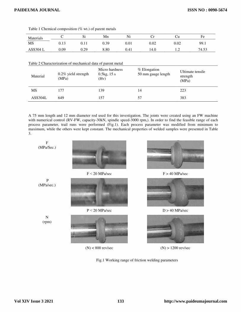
Table 1 Chemical composition (% wt.) of parent metals
Table 2 Characterization of mechanical data of parent metal
Material 0.2% yield strength (MPa)
Micro hardness 0.5kg, 15 s (Hv)
% Elongation 50 mm gauge length
Ultimate tensile strength (MPa)
MS 177 139 14 223
ASS304L 649 157 57 383
A 75 mm length and 12 mm diameter rod used for this investigation. The joints were created using an FW machine with numerical control (RV-FW, capacity-30kN, spindle speed-3000 rpm,). In order to find the feasible range of each process parameter, trail runs were performed (Fig.1). Each process parameter was modified from minimum to maximum, while the others were kept constant. The mechanical properties of welded samples were presented in Table 3.
F (MPa/Sec.)
F ˂ 20 MPa/sec F > 40 MPa/sec
P (MPa/sec.)
P ˂ 20 MPa/sec D > 40 MPa/sec
N (rpm)
(N) < 800 rev/sec (N) > 1200 rev/sec
Fig.1 Working range of friction welding parameters
Materials
MS
C Si Mn Ni Cr Cu Fe
0.13 0.11 0.39 0.01 0.02 0.02 99.1
ASS304 L 0.09 0.29 8.80 0.41 14.0 1.2 74.53
PAIDEUMA JOURNAL
Vol XIV Issue 3 2021
ISSN NO : 0090-5674
http://www.paideumajournal.com133

3. RESULT AND DISCUSSIONS
Fig.2 revealsthe effect of forging pressure on tensile strength of friction welded stainless steel (304L) to mild steel (AISI 1020) of joints.The tensile test results show that the forging pressure has a significant effect on the tensile strength of the joints. Tensile strength of the joints decreases with increasing in forging pressure from 20 MPa to 30 MPa and then increase beyond 30 MPa. The highest tensile strength of 468 MPa was obtained in the joint fabricated at a forging pressure of 20 MPa. The lowest strength of 450 MPa were observed in the joint fabricated at a forging pressure of 30 MPa.
Table 3 FW parameters used to fabricate the joints
Parameters N (rpm) F (MPa) P (MPa) Tensile strength (MPa)
Effect of Forging pressure
1000 20 30 410
1000 25 30 430
1000 30 30 453
1000 35 30 425
1000 40 30 400
Fig.2 Effect of forging pressure on tensile strength of FW joints
0
50
100
150
200
250
300
350
400
450
500
1 2 3 4 5
UTS "MPa"
UTS "Mpa"
PAIDEUMA JOURNAL
Vol XIV Issue 3 2021
ISSN NO : 0090-5674
http://www.paideumajournal.com134

Fig.3 shows the optical micrographs of symmetrically sectioned joints fabricated using different forging pressure and from the micrographs, the following observations can be made: friction pressure shows an appreciable influence on the resultant grain size at fully deformed zone (FDZ), partially deformed zone (PDZ) and HAZ. The coarse and elongated grains of base metal are completely changed into fine equiaxed grains in the FDZ of all the joints due to thermal flux[10-12]. In PDZ region, the grains are elongated with inclined positioning and the grains are coarser in size
compared to FDZ in all the joints.
Sl.No Fully deformed Partially deformed Heat affected zone
20
25
30
35
40
Fig. 3 Effect of forging pressure on microstructure
304L
50µm 50µm
304L
50µm 50µm
50µm
304L
50µm
50µm 50µm
304L
50µm 50µm
MS
MS
MS
MS
304L
50µm
50µm
MS
50µm
50µm
50µm
PAIDEUMA JOURNAL
Vol XIV Issue 3 2021
ISSN NO : 0090-5674
http://www.paideumajournal.com135

In HAZ, the grains are found to be equiaxed as seen in FDZ but larger in size[15-17]. As the forging pressure increases up to the certain level the grain size increases in all zones. Very fine grains are observed in the FDZ of the joint
fabricated at 20 MPa.
Table 4 Effect of forging pressure on fracture location
Sl. No
Macrostructure Before testing After testing Fracture location
20
Welded zone
25
Welded zone
30
HAZ
35
Welded zone
40
Welded zone
The fractured location of tensile tested specimens was scanned using digital scanner. Table 4shows the photographs of fractured sample after tensile testing. It is found from the fracture location of FW joints, that the forging pressure has a significant influence on the fracture location of the friction welded joints. The fracture location of joint fabricated at a
MS
MS
MS
MS
MS
304L
304L
304L
304L
304L
PAIDEUMA JOURNAL
Vol XIV Issue 3 2021
ISSN NO : 0090-5674
http://www.paideumajournal.com136

forging pressure of 20, 25, 35, 40 MPa occurred at the Weld zone. The fractured location of the joints fabricated at forging pressure of 30 MPa observed at HAZ. Table 4 shows the consolidated results of effect of forging pressure. It is well established in friction welding, that the frictional heat generation is inversely proportional to the forging pressure. The variations in temperature difference during forging force may be due to different contact conditions of tool and material such as sliding, sticking and partial sliding or sticking due to the frictional coefficient changes with momentarily local temperature of welding process.
4 DISCUSSION
At lower rotational speed (800 rpm), the tensile strength of FW joints is lower. When the rotational speed is increased from 800 rpm, correspondingly the tensile strength also increased and reaches a maximum at 1000 rpm. If the rotational speed is increased above 1000 rpm, the tensile strength of the joint decreased. This trend is common in all the joints irrespective of the bimetallic tubes. The tensile properties and fracture locations of the joints are to a large extent, dependent on the rotational speed, and other parameters. When the joints are associated with defects like HAZ, cracks in the FW region, the joints failed at the defective area and if the joints are defect free, the failure locations shifted to lowest hardness zone. Macrostructure observations showed that the joints fabricated at lower rotational speeds (800 rpm) contained defects in FW region as shown in Table3 and resulted in lower tensile properties. As rotational speed increased, the heat input per unit length of the joint increased, resulting inferior tensile properties due to rise in temperature, which increases grain growth. Considerable increase in turbulence, which destroys the regular flow behavior available at lower speed, is also observed. Moreover, a higher-rotational speed causes excessive release of welded materials to the upper surface, which resultants left voids in the weld zone. On the other side, the area of the weld zone decreases with decreasing the rotation speed and affect the temperature distribution in the weld zone. This lower heat input condition resulted in lack of welded in lower joint strength.
If the friction pressure is increased above 30 mm/s, the tensile strength of the joint decreased. When the joints areassociated macrostructure observations showed that the joints fabricated at lower friction pressure (20 mm/s) as shown in Table 2 contained defects like crack in FW region and resulted in lower tensile properties. On the other hand, joints fabricated at higher friction pressure (40 mm/s) as shown in Table 4 contained large-size defects and it appeared. In general, FW at higher friction pressure results in short exposure time in the weld area with insufficient heat and poor plastic flow of the metal and causes some voids like defects in the joints [18]. It seems that these voids are formed due to poor consolidation of the metal interface when the tool travels at higher-friction pressure. The friction pressure has a strong impact on productivity in streamlined production of FW of 304L & MS sections. A significant increase in friction pressure is achieved with high weld quality and excellent joint properties. The softened area is narrower for the higher-friction pressure than that for the lower friction pressure. Thus, the tensile strength of as welded stainless steel to mild steel has a proportional relationship with friction pressure. Higher-friction pressure is associated with low heat inputs, which result in faster cooling rates of the welded joint. This can significantly reduce the extent of metallurgical transformations taking place during welding regions across the weld zone[19]. When the friction pressure is slower than a certain critical value, the FW can produce defect-free joints. When the friction pressure is faster than the critical value, welding defects can be produced in the joints. The defects act as a crack initiation site during tensile test. Therefore, the tensile properties and fracture locations of the joints are determined by the friction pressure. Macrostructure observations showed that the joints fabricated at lower forging pressure (20 MPa) contained defects like crack in FW region and resulted in lower tensile properties. On the other hand, joints fabricated at higher forging pressure (40 MPa) contained large-size defects and it appeared. In general, FW at higher forging pressure results in short exposure time in the weld area with insufficient heat and poor plastic flow of the metal and causes some voids like defects in the joints. It seems that these voids are formed due to poor consolidation of the metal interface when the tool travels at higher- forging pressure. The forging pressure has a strong impact on productivity in streamlined production of FW of (304L) to MS sections. A significant increase in forging pressure is achieved with high weld quality and excellent joint properties. The softened area is narrower for the higher- forging pressure than that for the lower forging pressure. Thus, the tensile strength of as welded stainless steel to mild steel has a proportional relationship with forgingpressure. Higher- forging pressure are associated with low heat inputs, which result in faster cooling rates of the welded joint. This can significantly reduce the extent of metallurgical transformations taking place during welding regions across the weld zone. When the forging pressure is slower than a certain critical value, the FW can produce defect-free joints. When the forging pressure is faster than the critical value, welding defects can be produced in the joints. The defects act as a crack initiation site during tensile test [20]. Therefore, the tensile properties and fracture locations of the joints are determined by the forging pressure. The softened area was narrower for the higher- forging pressure than that for the lower- forging pressure.
PAIDEUMA JOURNAL
Vol XIV Issue 3 2021
ISSN NO : 0090-5674
http://www.paideumajournal.com137

SUMMARY
1. Dissimilar combinations of materials were successfully welded. The mechanism of welding for Stainless Steel (304 L) to Mild steel (AISI 1020) was studied.
2. All dissimilar material failed in the weld irrespective of friction welding parameters. However, when the stainless-steel composition was changed to 304LSteel, some samples failed on the MS side, some failed in the weld and others failed on the Stainless-Steel side.
3. It can be concluded that failure location depends upon the friction welding parameters. In the case of 304L to MS, failure was at the weld for most of the friction welding parameters which were tried out.
4. Weld failure could be shifted slightly to the MS side only after lot of experimentation with the input friction welding parameters. Tensile strength of high welds varied from 400 MPa to 4653 MPa depending upon the friction welding conditions used.
5. The joint welded with rotational speed of 1000 rpm, forging pressure of 30MPa/sec and axial force of 30MPa/sec conceived a maximum tensile strength of 453 MPa.
REFERENCES
[1] Pouraliakbara, B.H., Hamedia, M., Kokabia, A.H., and Nazarib, A, 2014, Designing of CK45 Carbon Steel and AISI 304 Stainless Steel Dissimilar Welds, Materials Research, Vol. 17(1), pp 106-114.
[2] Tayyab, I: Analysis of Dissimilar Metal Welding of 1020 Mild Steel and 304 Stainless Steel, 2014, Master Thesis, Department of Mechanical Engineering, National Institute of Technology, Rourkela.
[3] Oladele, I.O.; Omotoyinbo, J.A.; and Akinwekomi, A.D, 2010, The Effect of Weld Goemetry and Post Weld Heat Treatment on the Corrosion Behaviour of Austenitic Stainless Steel Immersed in 1.0 M NaCl Solution, Material Research, vol.13(1), pp 405- 418.
[4] Giridharan, S. Kannan, T.M., Balamurugan, K.; Kumar, A.., and Vignesh: Experimental Investigation and Analysis of Dissimilar welding of AISI 316L and IS 2062 using GTAW, ,2016,International Journal of Innovative Research in Science, Engineering and Technology, vol.5(6), pp 11052-11058.
[5] Oladele, I.O., Betiku, O.T., and Fakoya, M.B,2017, Effect of Post Weld Heat Treatment on the Mechanical and Corrosion Behaviour of Welded Al-Fe-Si Alloy Joints, Leonardo Electronic Journal of Practice and Technologies, vol.30, pp. 75-86.
[6] Tanaka, T.; Morishige, T.; and Hirata, T, 2009, Comprehensive Analysis of Joint Strength for Dissimilar Friction Stir Welds of Mild Steel to Aluminum Alloys, Scripta Materialia, vol. 61, pp 756–759.
[7] Shahid, F., Khan, A.A., and Hameed, M.S, 2015, Mechanical and Microstructural Analysis of Dissimilar Metal Welds, International Journal of Research and Reviews in Applied Sciences, vol.25(1), pp 6-14.
[8] Jamaludin, S.B.; Noor, M.M.; Kadir, S.K.; and Ahmad, K.R, 2013, Mechanical Properties of Dissimilar Welds between Stainless Steel and Mild Steel, Advanced Materials Research, vol.795,pp 74-77.
[9] ASTM A370-08A: Standard Test Methods and Definitions for Mechanical Testing of Steel Products, 2008, ASTM international.
[10] ASTM E190-92: Standard Test Method for Guided Bend Test for Ductility of Welds, , 2008, ASTM International, Re-approved.
[11] Muralimohan, C.H.; Haribabu, S.; Hariprasada, R., Muthupandi, V and Siva Prasad, K, 2014, Evaluation of Microstructures and Mechanical properties of Dissimilar Materials by Friction Welding, Procedia. Materials Science, vol.5, pp 1107-1113.
[12] Andrés, G.F., Rafael, S.A., Leiry, C.B., and Alberto, V.R, Crack growth study of dissimilar steels (Stainless-Structural) butt welded unions under cyclic loads,2011, Procedia. Engineering, vol.10, pp.1917–1923.
[13] Hsieh C.C., Lin D.Y., Chen M.C.., and Wu W, 2007, Microstructure, Recrystallization, and Mechanical Property Evolutions in the Heat-Affected and Fusion Zones of the Dissimilar Stainless Steels, Materials Transactions, vol. 48(11),pp 2898-2902.
[14] Rajendran, C., K. Srinivasan, V. Balasubramanian, H. Balaji, and P. Selvaraj. 2018, Identifying the combination of friction stir welding parameters to attain maximum strength of AA2014-T6 aluminum alloy joints. Advances in Materials and Processing Technologies vol.4, no. 1, pp. 100-119.
[15] Rajendran, C., K. Srinivasan, V. Balasubramanian, H. Balaji, and P. Selvaraj. 2019, Identifying combination of friction stir welding parameters to maximize strength of lap joints of AA2014-T6 aluminium alloy. Australian Journal of Mechanical Engineering vol.17, no. 2, pp 64-75.
[16] Fewell M. P. and J. M. Priest, 2008, High-order diffractometry of expanded austenite using synchrotron radiation, Surf. Coatings Technol., vol. 202, no 9, pp 1802–1815).
[17] Christiansen T and M. A. J. Somers,2004, On the crystallographic structure of S-phase, Scr. Mater., vol.50, no.1, pp 35–37. [18] Farrell K, E. D. Specht, J. Pang, L. R. Walker, A. Rar, and J. R.2005, Mayotte, Characterization of a carburized surface layer
on an austenitic stainless steel, J. Nucl. Mater., vol.343, no 1–3, pp 123–133. [19] Michal G M, F. Ernst, and A. H. Heuer,2006, Carbon para equilibrium in austenitic stainless steel, Metall. Mater. Trans. A,
vol. 37, no. pp 1819–1824. [20] Oddershede J, T. L. Christiansen, K. Ståhl, and M. A. J. Somers, Extended X-ray absorption fine structure investigation of
nitrogen stabilized expanded austenite, Scr. Mater., vol.62, no 5, pp 290–293.
PAIDEUMA JOURNAL
Vol XIV Issue 3 2021
ISSN NO : 0090-5674
http://www.paideumajournal.com138