

Reader materials and structures: 5. Aircraft & spacecraft structures
1
IMPACT ENGINEERING
FOR MATERIALS AND STRUCTURES
Professor Guoxing Lu
Chair, Dept of Mechanical and Product Design Engineering
Faculty of Science, Engineering and Technology
Swinburne University of Technology, Melbourne, Australia
5th International Conference on Advances in Mechanical Engineering
August 16-18, 2017 Krabi, Thailand

OUTLINE OF PRESENTATION
• INTRODUCTION
• THIN-WALLED STRUCTURES
• POROUS AND CELLULAR SOLIDS
• SANDWICH PANELS
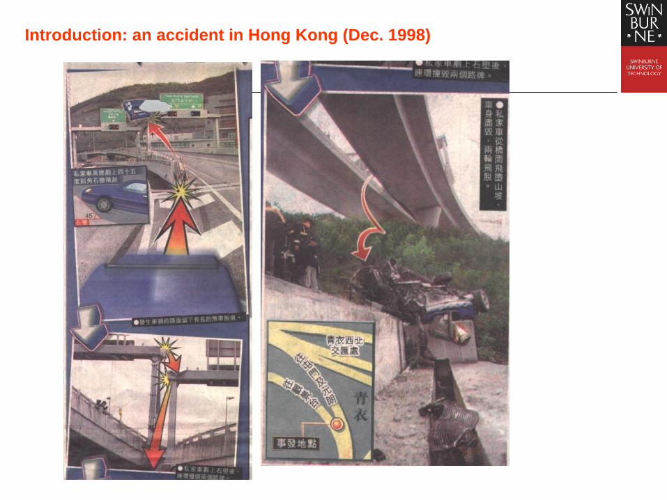
Introduction: an accident in Hong Kong (Dec. 1998)

Gadd Severity Index (GSI)
000,10
5.2 T
dtaGSI
Head Injury Criterion (HIC)
000,1)(1
)max(...
5.2
12
12
2
1
t
t
dttatt
ttCIH


Thin-walled Structures: axial crushing of
circular tubes [Guillow, Grzebieta]

Thin-walled Structures: Deformed specimen from
FEA and experiment [Huang Xiaodong]
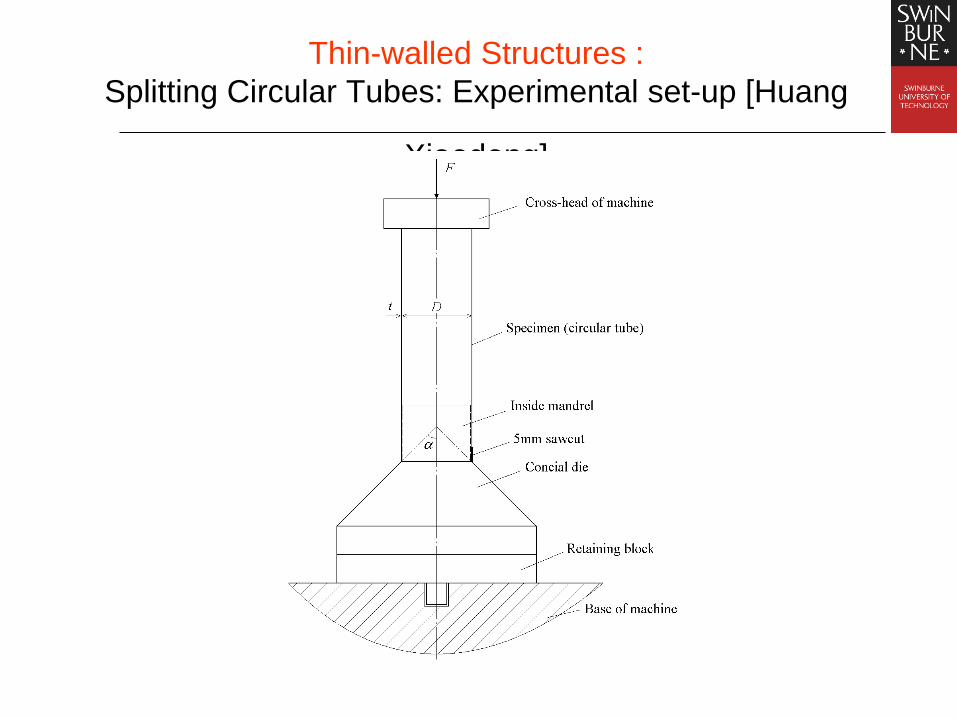
Thin-walled Structures :
Splitting Circular Tubes: Experimental set-up [Huang
Xiaodong]

Typical force-displacement curves for mild steel
tubes with D=74.0mm, t=1.8mm

Photographs of typical mild steel specimens
6045 75
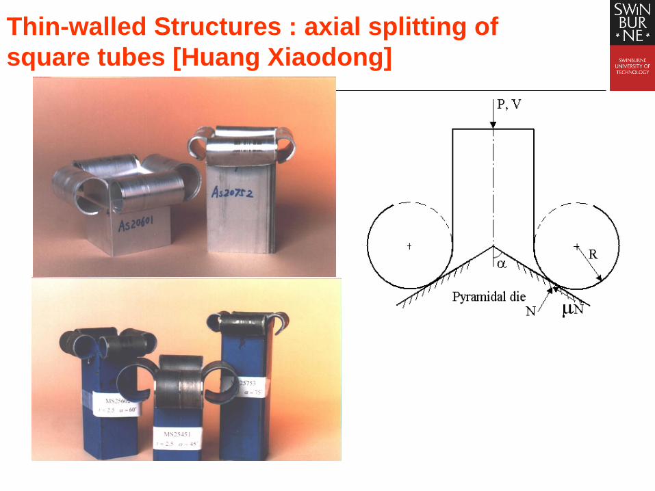
Thin-walled Structures : axial splitting of
square tubes [Huang Xiaodong]
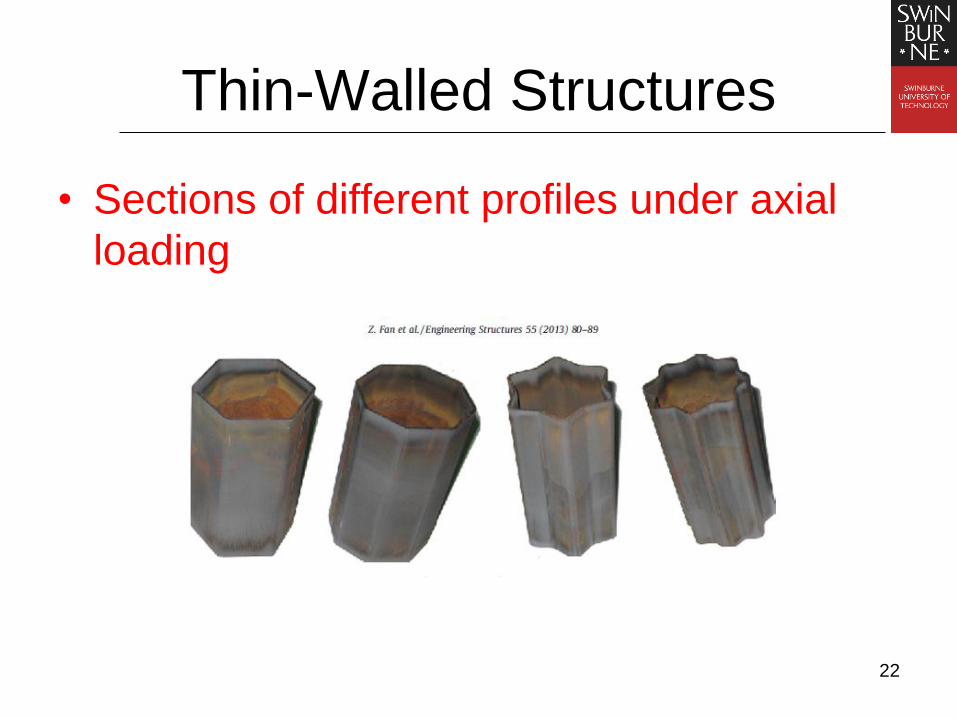
Thin-Walled Structures
• Sections of different profiles under axial
loading
22
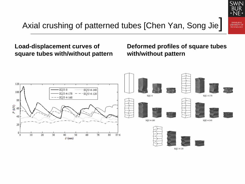
Axial crushing of patterned tubes [Chen Yan, Song Jie]
Load-displacement curves of
square tubes with/without pattern
Deformed profiles of square tubes
with/without pattern
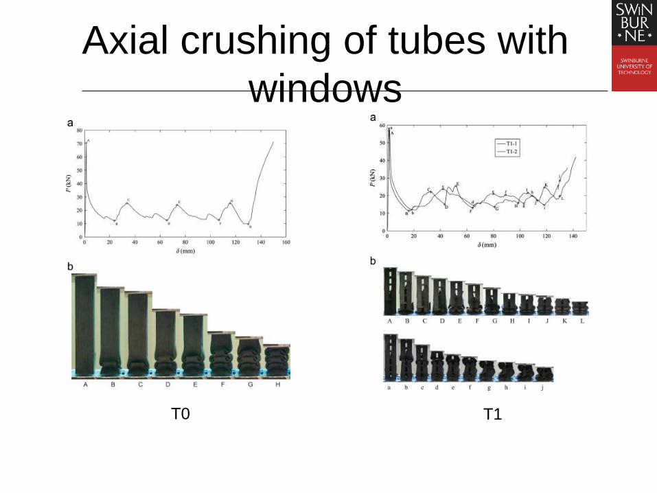
Axial crushing of tubes with
windows
T0 T1

Thin-walled Structures: Bending of rectangular
beams [Huang Xiaodong]

FEA result:
Angle=0, 50, 100, 150, 200, 250 and 300
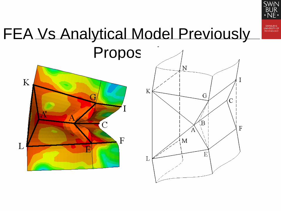
FEA Vs Analytical Model Previously
Proposed

Non-dimensional Plot
tb
M2
0vs. angle in radian
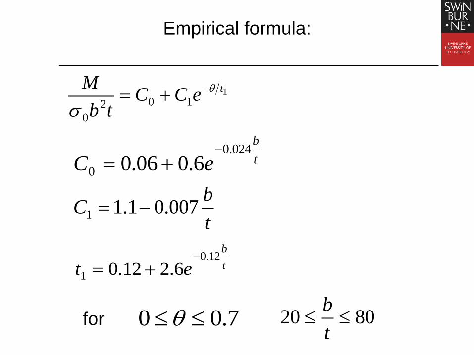
Empirical formula:
1102
0
teCC
tb
M
7.00
t
b
eC024.0
0 6.006.0
8020 t
b
t
bC 007.01.11
t
b
et12.0
1 6.212.0
for

HONG KONG STARTS TO INSTALL NEW
GUARDRAILS (SING TAO, 7/1/02)

35
Composite Structures
Carbon fibre composites
Fig. 10. The deformation modes of empty CFRP tubes at a velocity
of: (a) 0.05 mm/s, (b) 0.5 mm/s, (c) 5 mm/s and (d) 50 mm/s.

36
Composite Structures

COLLISION OF SHIPS: CUTTING OF A PLATE BY A WEDGE
[Calladine]

Lu & Calladine, Int J Mech Sci, 32, 293-313, 1990
SHIP COLLISION: CUTTING OF A PLATE BY A WEDGE
7.13.13.1 tYlCW
39
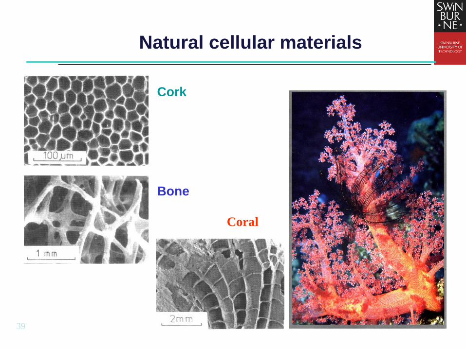
Natural cellular materials
Cork
Bone
Coral
40
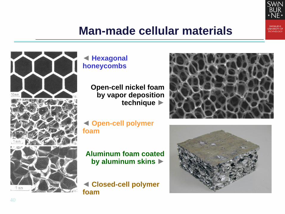
Man-made cellular materials
◄ Hexagonal honeycombs
Open-cell nickel foam by vapor deposition
technique ►
◄ Open-cell polymer foam
Aluminum foam coated by aluminum skins ►
◄ Closed-cell polymer foam

41
Cellular Materials used
for Energy Absorption

Typical stress-strain curves of cellular
materials
Densification Strain (locking strain):
1 1d s Theoretically:
Practically: 1 1.4d
43
Stress level rises
with relative density

Introduction: dynamic effects
General impact behavior of cellular materials
– Quasi-static loading: Elastic stage, plateau stage, densification
– Dynamic loading: Dynamic enhancement, compaction waves
¦Å¦Åd
¦ Ò
¦ Òp
plateau stage
R-P-P-L model
densification
elastic stage
Typical distributions of cell deformation for the initial
impact velocities of (a) V=107.5 m/s and (b) V=22.4 m/s,
respectively (Tan et al. 2005)
Tan PJ, Reid SR, Harrigan JJ, Zou Z, Li S. Dynamic compressive strength properties of aluminum foams. Part I ——
experimental data and observations. J Mech Phys Solids 2005;53(10):2174-205.
Static stress-strain relationship of the cellular
material and the R-P-P-L material model
44

Introduction
• Rigid, perfectly-plastic, locking (R-PP-L) material model
20d p
d
V
• Critical velocity based on Wave trapping theory
0
cr
crV c d
0c d d Velocity of the stress wave
For elastic, perfectly plastic
material,
, cr Yd d E E
0
YcrV
E
45

Experiments
• Testing equipments
Instron High Speed Testing System
Split Hopkinson
Pressure Bar
MTS Machine

Material Responses: A typical aluminium honeycomb
specimen and an intact honeycomb cell [Ruan Dong]
47
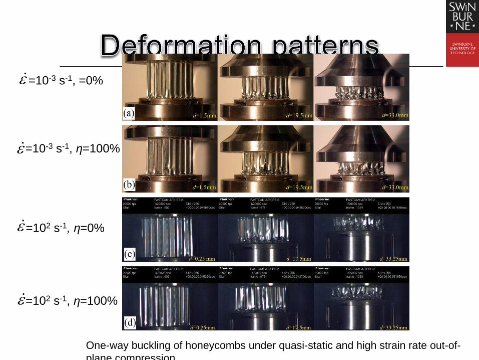
=10-3 s-1, =0%
=10-3 s-1, η=100%
=102 s-1, η=0%
=102 s-1, η=100%
One-way buckling of honeycombs under quasi-static and high strain rate out-of-
plane compression

Material Responses: aluminium foams
[Ruan Dong]

Experiments Table 2. Nominal specimen dimensions
Specimen Types
Diameter (D,
mm)
Length (L, mm)
I 50 50
II 50 25
Alporas 10% 50mm*50mm Cymat 10% 50mm*50mm Cymat 17% 50mm*25mm

Results and discussion
0.0 0.2 0.4 0.6 0.8
0
2
4
6
8
10
E
ng
ine
eri
ng
str
ess,
, M
Pa
Engineering strain,
strain rate=10-1
s-1
/s=7.86%
strain rate=10-1
s-1
/s=10.76%
strain rate=10-1
s-1
/s=9.03%
strain rate=10-1
s-1
/s=8.63%
strain rate=10-1
s-1
/s=9.80%
strain rate=10-3
s-1
/s=9.74%
strain rate=102 s
-1 /
s=8.30%
strain rate=102 s
-1 /
s=11.34%
strain rate=102 s
-1 /
s=9.03%
strain rate=102 s
-1 /
s=8.65%
strain rate=102 s
-1 /
s=10.26%
Stress-strain curves for Alporas foams at different strain rates
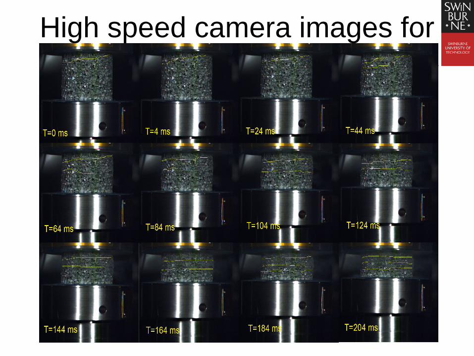
High speed camera images for
Alporas foams
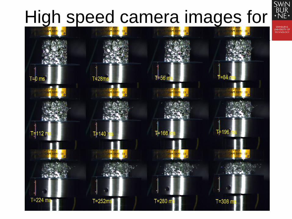
High speed camera images for
Cymat foams
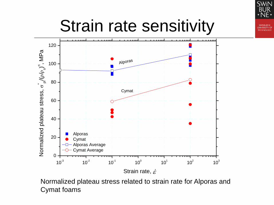
Strain rate sensitivity
10-3
10-2
10-1
100
101
102
103
0
20
40
60
80
100
120
Alporas
Cymat
Alporas Average
Cymat Average
No
rma
lize
d p
late
au
str
ess,
* pl/(/
s)n
, M
Pa
Strain rate,
Alporas
Cymat
Normalized plateau stress related to strain rate for Alporas and
Cymat foams

Direct impact of cellular
materials

Metals and Composites 金属和复合材料
Tensile test on TWIP steel at 20 m/s
双相钢
76
Tensile test on Kevlar at 5 m/s
Kevlar复合材料

Testing Facilities
77
High speed camera (probably the
latest camera in Australia) Phantom v2512
•Speed over 25,000 frames-per-second at full
resolution
•1280 x 800 resolution
•1 µs minimum exposure standard
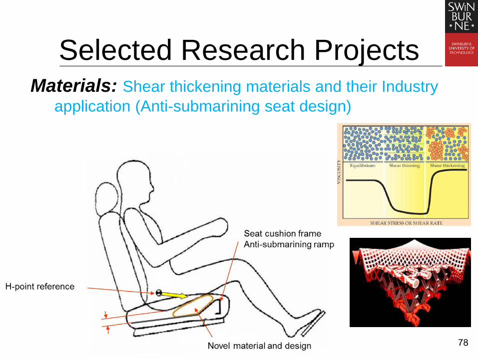
Selected Research Projects Materials: Shear thickening materials and their Industry
application (Anti-submarining seat design)

79
Selected Research Projects Structures: Hybrid tubes
three-point bending of foam filled tubes Intrusion beam
Orange, intrusion
beams of a sedan
(Bryant, 2006).
http://www.ford.com/microsites/sustainability-report-2008-09/issues-vehicle-
performance-vehiclesafety-occupant
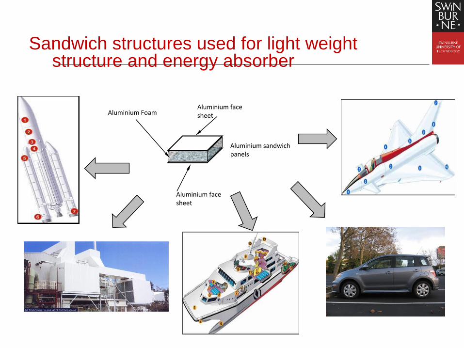
Sandwich structures used for light weight structure and energy absorber
Aluminium face sheet Aluminium Foam
Aluminium sandwich panels
Aluminium face sheet
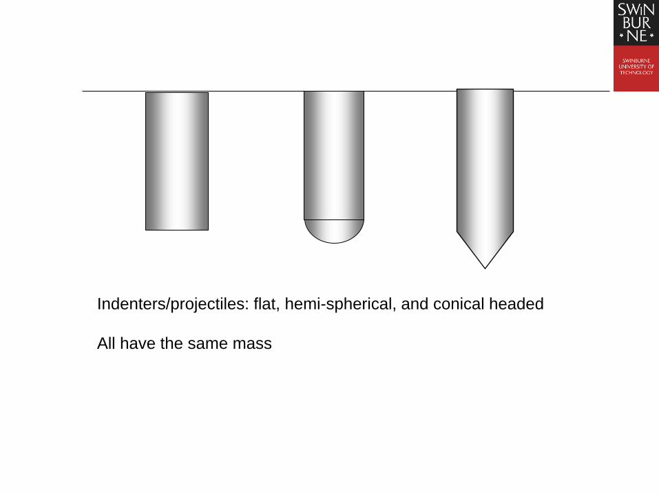
Indenters/projectiles: flat, hemi-spherical, and conical headed
All have the same mass

Preparation of the specimens:

Experiment set-up for impact perforation tests:
Impact perforation tests using gas gun • Highest allowable gas pressure: 15MPa
• Highest speed possible: 400m/second
• Internal diameter of the barrel : 12.50mm


Results and discussion (1) - impact velocity
A plot showing the relationship of impact velocity and the ratio of dynamic
and quasi-static perforation energy. (Hemi-spherical head)
60 80 100 120 140 160 180 200
1.0
1.2
1.4
1.6
1.8
2.0
2.2
2.4
2.6(E
d/E
s )
Vi (m/s)
Φ :dynamic enhancement
factor,
: Dynamic energy:
: Static energy,
: Impact velocity
21
2p p bE m V

98
Sandwich panels subjected to
foam projectile impact
Experimental Setup
A cylindrical
foam projectile A photograph of the
experimental setup
M.A. Yahaya, D. Ruan, G. Lu , M.S. Dargusch
International Journal of Impact Engineering 75 (2015)
100
99
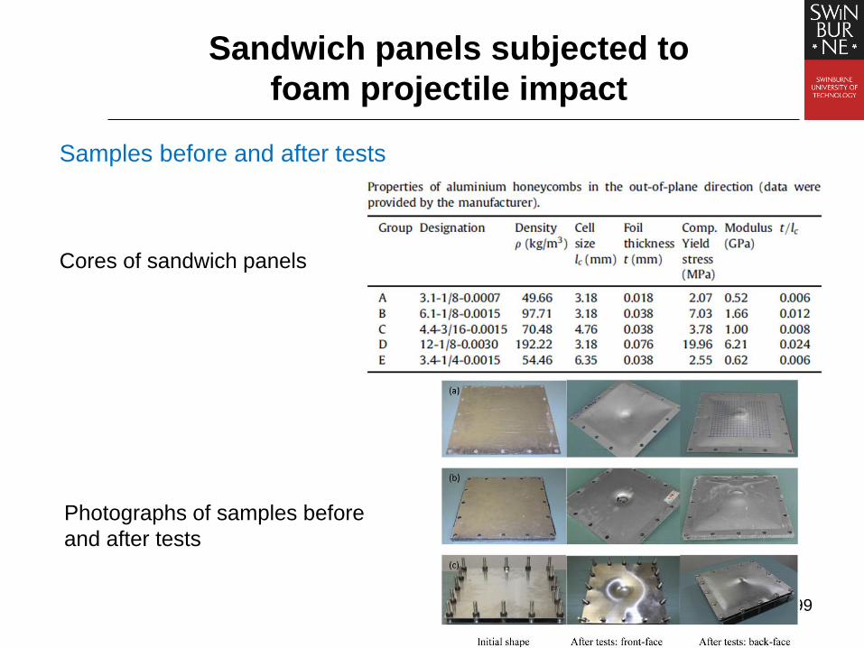
Samples before and after tests
Sandwich panels subjected to
foam projectile impact
Photographs of samples before
and after tests
Cores of sandwich panels

100
Deformation of sandwich panels with various aluminium honeycomb cores
Sandwich panels subjected to
foam projectile impact

101
Deformation of sandwich panels, air sandwich panels and monolithic plates
Sandwich panels subjected to
foam projectile impact
Comparison between sandwich panels
with various aluminium honeycomb cores
Comparison between sandwich
panels (A, B and C), air sandwich
panels (G) and monolithic plates (M)

102
Sandwich panels: Blast threats to engineering
structures [Zhu Feng, Shen Jianhu, Zhao Long
Mao, Wang Zhihua]
Murrah Building, Oklahoma City, 1995
Bishopsgate, London, 1993
Russian armored car, Chechenia, 2000 US navy ship, Yemen, 2000
Central railway station, Madrid, 2004
Structural
fracture
Progressive
collapse
Large plastic
deformation
& Ballistic
penetration
103
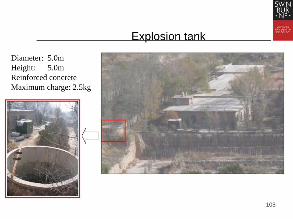
Explosion tank
Diameter: 5.0m
Height: 5.0m
Reinforced concrete
Maximum charge: 2.5kg

104
Sketch of the whole experimental setup
PVDF pressuregauge
Speci menCharge
Four-cable ballistic pendulum

106
Sandwich panel: Honeycomb core panels (HCP)
Geometry of the core
Dimension of the panel
Specimen
fc
L
L = 300mm
c = 12.5 mm
f = 0.5mm; 0.8mm; 1.0mm

109
Experimental observations
(1) Front face-sheet deformation/failure
Global deformation (Mode G) Localized deformation (Mode L)

116
Empirical equation for predicting the back face
deflections

117
Geometry and dimension of specimens –
Aluminium foam core panels (AFCP)
Aluminium foam core
Specimen
• Relative density of core (6% and 10%)
• Face thickness (0.8 and 1.0mm)
• Mass of charge (20g, 30g and 40g)
10 panels were tested and
3 parameters were analyzed:

120
Core failure

121
FE simulation (HCP panels)
Geometric model:
A cell (enlarged)
Charge (enlarged)
With LS-DYNA 970
• Face-sheets and core: Bi-linear elasto-plastic material
• Charge: High explosive
Material model:

122
Phase I: Process of the charge explosion
t=0 t=5 μs t=8 μs
t=13 μs t=25 μs t=30 μs

123
Phase II: Process of explosion product – structure
interaction
t=32 μs t=38 μs t=43 μs
t=52 μs t=62 μs t=58 μs
124
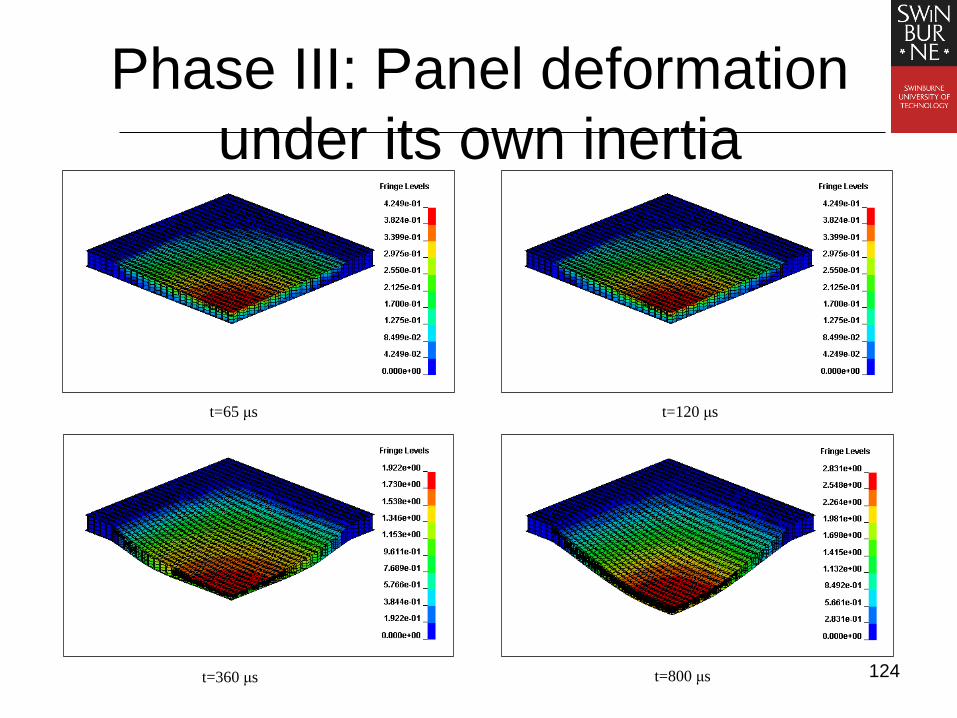
Phase III: Panel deformation
under its own inertia
t=65 μs t=120 μs
t=360 μs t=800 μs
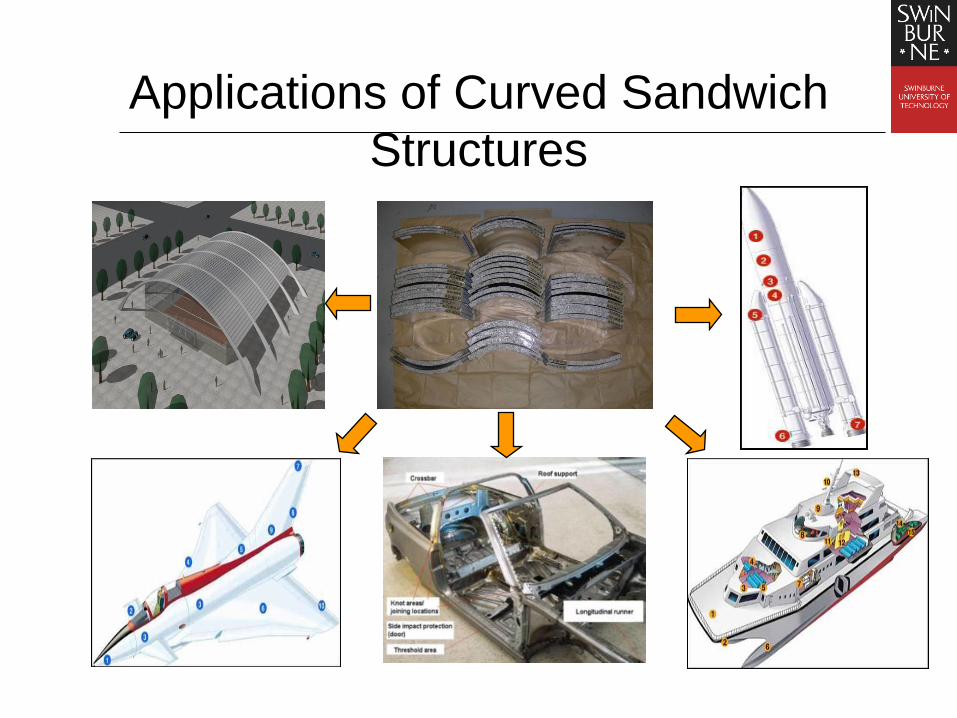
Applications of Curved Sandwich
Structures

Curved sandwich panels
Material: ALPORAS® Aluminium Foam
Length:400mm
Width:400mm
Face sheet thickness:0.5-1.6mm
Core thickness:10~30mm
Radius of curvature: 300-600mm
Large block of
metal foam
Aluminium alloy
5005 H34
sheets
FORTIS AD825
epoxy liquid glue
Frames for
Clamping the
specimen during
curing
700
2400
1800
40
0
90
0

Pendulum system
• Length: 2.5m
• Width: 0.5m
• Height: 2.62m
• Total Weight:
161-167Kg
• Period: 3.0-
3.2s
• Balance
weight: 49.8kg

Deformation/failure patterns-front
face
Global deformation
Local indentation
Wrinkling

Deformation/failure patterns-Back
face
Global deformation
Wrinkling

FE model validation
(2) deformation profile
Fully bonded
Corresponding
experiments

FE model validation
(2) deformation profile
Without bonding
Corresponding
experiments

Bio-Impact Mechanics
冲击动力学在生物医学方面的应用
154
Craniectomy protective headgear
开颅手术后病人带的头部保护罩
CT Exoband protective helmet
A flex protective headgear, Orthomerica
Q cap, KLS Martin Group
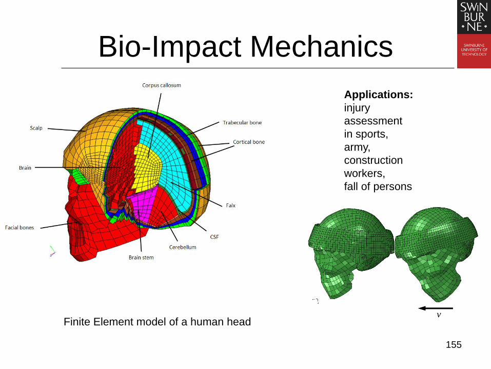
Bio-Impact Mechanics
155
v Finite Element model of a human head
Applications:
injury
assessment
in sports,
army,
construction
workers,
fall of persons

Bi-directional Evolutionary Structural
Optimization(BESO)
Optimization algorithm: Remove low-efficient
materials and add high-efficient materials to the
ground structure.
Advantages: Simple concept; Easily
implementation; Robustness and high efficiency
Applications: Optimization of Structures and
Materials
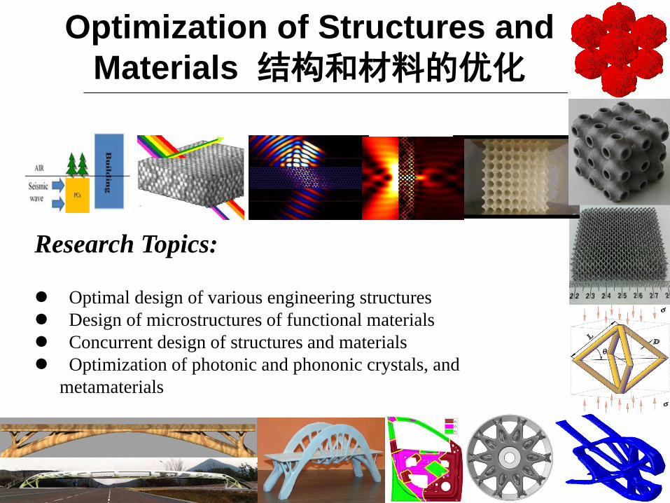
Optimization of Structures and
Materials 结构和材料的优化
Research Topics: Optimal design of various engineering structures
Design of microstructures of functional materials
Concurrent design of structures and materials
Optimization of photonic and phononic crystals, and
metamaterials

158
(卢国兴、余同希, Energy Absorption of Materials and
Structures, Woodhead Publishing, Cambridge,UK,2003;
中文版: 化学工业出版社2006)

Conclusion and future work
• Cellular materials and their structures offer good energy absorption performance
• Their structural performance can be adjusted and may be optimised in design
• Design concept should be extended to other areas of applications in industries such as mining and sports, and civil engineering!
• Concrete/steel structures, composites (FRP)