Impact and Crash Modeling of Composite Structures: A...
21
EURO-PAM’99 Impact and Crash Modeling of Composite Structures: A Challenge for Damage Mechanics Dr. A. Johnson – DLR Dr. A. K. Pickett – ESI GmbH
Transcript of Impact and Crash Modeling of Composite Structures: A...
EURO-PAM’99
Impact and Crash Modeling of Composite Structures:
A Challenge for Damage Mechanics
Dr. A. Johnson – DLRDr. A. K. Pickett – ESI GmbH

Impact and Crash Modelling of Composite Structures: A Challenge for Damage Mechanics
Alastair Johnson German Aerospace Center (DLR)
Institute of Structures and Design, Stuttgart e-mail: [email protected]
Anthony Pickett
Engineering Systems International GmbH Eschborn
e-mail: [email protected]
ABSTRACT The paper describes recent progress on the materials modelling and numerical simulation of the crash and impact response of fibre reinforced composite structures. Composite materials are now being used in primary aircraft structures, particularly in helicopters, light aircraft, commuter planes and sailplanes, because of numerous advantages including low weight, high static and fatigue strength and the possibility to manufacture large integral shell structures. Materials such as carbon fibre/epoxy are inherently brittle and usually exhibit a linear elastic response up to failure with little or no plasticity. Thus composite structures are vulnerable to impact damage and have to satisfy certification procedures for high velocity impact from runway debris or bird strike. Conventional metallic structures absorb impact and crash energy through plastic deformation and folding. Modern explicit FE codes such as PAM-CRASH are able to model these effects and are being successfully applied to simulate the collapse of metallic aircraft and automotive structures. This paper is concerned with the further development and improvement of such codes for modelling the response of composite structures under crash and impact loads. This topic is being studied in some detail within a CEC funded research project on 'High velocity impact of composite aircraft structures' HICAS [1]. This project includes an extensive composites materials and structures test programme, composites modelling developments, FE code implementation and impact simulations. Two important aspects of impact modelling are delamination, which is important in lower energy impacts and in failure initiation, and in-plane ply failure which controls ultimate failure and penetration in the structure. This paper summarises some of the modelling developments being carried out within the HICAS project on in-plane damage models for both unidirectional (UD) and fabric reinforced composite plies. Emphasis is given to composite materials models suitable for implementation into explicit FE codes, which can adequately characterise the nonlinear damage progression and different failure modes that occur in composites. A continuum damage mechanics model for composite plies under in-plane loads is presented. It is based on methods developed for UD ply materials in [2], which are generalised to fabric reinforcements. This model has a number of features not included in the existing 'bi-phase' model. It allows damage parameters for in-plane and through-thickness shear failure modes, as well as failures along and transverse to the fibre directions. Delamination models and strain rate dependence may also be incorporated in the damage mechanics framework. The model contains elastic damage in the fibre directions, with an elastic-plastic model for inelastic shear

effects. A novel approach is being developed for delamination modelling based on laminates modelled numerically as stacked plies, with a new sliding interface whose failure properties are consistent with the fracture mechanics of composite delamination. The models are currently being implemented into PAM-CRASH and preliminary results are presented on simulations of impacted composite plates and progressive delamination.
REFERENCES
[1] HICAS High Velocity Impact of Composite Aircraft Structures, CEC DG XII BRITE-EURAM Project BE 96-4238 (1998).
[2] P. Ladeveze, E. Le Dantec, Damage modelling of the elementary ply for laminated composites, Composites Science and Technology, 43, 257-267 (1992).

1
Deutsches Zentrum für Luft- und Raumfahrt e.V. German Aerospace CenterInstitute of Structures and Design, Stuttgart
Impact and Crash Modelling of Composite Structures:A Challenge for Damage Mechanics
Alastair JohnsonGerman Aerospace Center (DLR)
Institute of Structures and Design, Stuttgarte-mail: [email protected]
Anthony PickettEngineering Systems International GmbH
Eschborne-mail: [email protected]
ABSTRACTThe paper describes recent progress on the materials modelling and numerical simulation of thecrash and impact response of fibre reinforced composite structures. Composite materials are nowbeing used in primary aircraft structures, particularly in helicopters, light aircraft, commuterplanes and sailplanes, because of numerous advantages including low weight, high static andfatigue strength and the possibility to manufacture large integral shell structures. Materials suchas carbon fibre/epoxy are inherently brittle and usually exhibit a linear elastic response up tofailure with little or no plasticity. Thus composite structures are vulnerable to impact damage andhave to satisfy certification procedures for high velocity impact from runway debris or bird strike.Conventional metallic structures absorb impact and crash energy through plastic deformation andfolding. Modern explicit FE codes such as PAM-CRASH are able to model these effects and arebeing successfully applied to simulate the collapse of metallic aircraft and automotive structures.This paper is concerned with the further development and improvement of such codes formodelling the response of composite structures under crash and impact loads. This topic is beingstudied in some detail within a CEC funded research project on ’High velocity impact ofcomposite aircraft structures’ HICAS [1]. This project includes an extensive composites materialsand structures test programme, composites modelling developments, FE code implementation andimpact simulations.

2
Deutsches Zentrum für Luft- und Raumfahrt e.V. German Aerospace CenterInstitute of Structures and Design, Stuttgart
Two important aspects of impact modelling are delamination, which is important in lower energyimpacts and in failure initiation, and in-plane ply failure which controls ultimate failure andpenetration in the structure. This paper summarises some of the modelling developments beingcarried out within the HICAS project on in-plane damage models for both unidirectional (UD)and fabric reinforced composite plies. Emphasis is given to composite materials models suitablefor implementation into explicit FE codes, which can adequately characterise the nonlineardamage progression and different failure modes that occur in composites. A continuum damagemechanics model for composite plies under in-plane loads is presented. It is based on methodsdeveloped for UD ply materials in [2], which are generalised to fabric reinforcements. This modelhas a number of features not included in the existing ’bi-phase’ model. It allows damageparameters for in-plane and through-thickness shear failure modes, as well as failures along andtransverse to the fibre directions. Delamination models and strain rate dependence may also beincorporated in the damage mechanics framework. The model contains elastic damage in the fibredirections, with an elastic-plastic model for inelastic shear effects. A novel approach is beingdeveloped for delamination modelling based on laminates modelled numerically as stacked plies,with a new sliding interface whose failure properties are consistent with the fracture mechanics ofcomposite delamination. The models are currently being implemented into PAM-CRASH andpreliminary results are presented on simulations of impacted composite plates and progressivedelamination.
REFERENCES
[1] HICAS High Velocity Impact of Composite Aircraft Structures, CEC DG XII BRITE-EURAM Project BE 96-4238 (1998).
[2] P. Ladeveze, E. Le Dantec, Damage modelling of the elementary ply for laminatedcomposites, Composites Science and Technology, 43, 257-267 (1992).
3
Deutsches Zentrum für Luft- und Raumfahrt e.V. German Aerospace CenterInstitute of Structures and Design, Stuttgart
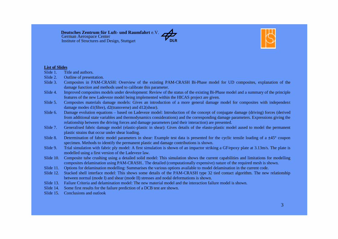
List of SlidesSlide 1. Title and authors.Slide 2. Outline of presentation.Slide 3. Composites in PAM-CRASH: Overview of the existing PAM-CRASH Bi-Phase model for UD composites, explanation of the
damage function and methods used to calibrate this parameter.Slide 4. Improved composites models under development: Review of the status of the existing Bi-Phase model and a summary of the principle
features of the new Ladeveze model being implemented within the HICAS project are given.Slide 5. Composites materials damage models: Gives an introduction of a more general damage model for composites with independent
damage modes d1(fibre), d2(transverse) and d12(shear).Slide 6. Damage evolution equations – based on Ladeveze model: Introduction of the concept of conjugate damage (driving) forces (derived
from additional state variables and thermodynamics considerations) and the corresponding damage parameters. Expressions giving therelationship between the driving forces and damage parameters (and their interaction) are presented.
Slide 7. Generalised fabric damage model (elastic-plastic in shear): Gives details of the elasto-plastic model aused to model the permanentplastic strains that occur under shear loading.
Slide 8. Determination of fabric model parameters in shear: Example test data is presented for the cyclic tensile loading of a ±45° couponspecimen. Methods to identify the permanent plastic and damage contributions is shown.
Slide 9. Trial simulation with fabric ply model: A first simulation is shown of an impactor striking a GF/epoxy plate at 3.13m/s. The plate ismodelled using a first version of the Ladeveze law.
Slide 10. Composite tube crushing using a detailed solid model: This simulation shows the current capabilities and limitations for modellingcomposites delamination using PAM-CRASH.. The detailed (computationally expensive) nature of the required mesh is shown.
Slide 11. Options for delamination modelling: Summarises the various options available to model delamination in the current code.Slide 12. Stacked shell interface model: This shows some details of the PAM-CRASH type 32 tied contact algorithm. The new relationship
between normal (mode I) and shear (mode II) stresses and nodal deformations is shown.Slide 13. Failure Criteria and delamination model: The new material model and the interaction failure model is shown.Slide 14. Some first results for the failure prediction of a DCB test are shown.Slide 15. Conclusions and outlook

4
Deutsches Zentrum für Luft- und Raumfahrt e.V. German Aerospace CenterInstitute of Structures and Design, Stuttgart
Impact and Crash Modelling of Composite Structures:A Challenge for Damage mechanics
Alastair JohnsonDLR Institute of Structures and Design
Stuttgart, Germany
Anthony Pickett Engineering Systems International GmbH
Eschborn, Germany
5
Deutsches Zentrum für Luft- und Raumfahrt e.V. German Aerospace CenterInstitute of Structures and Design, Stuttgart
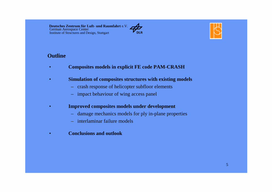
Outline
• Composites models in explicit FE code PAM-CRASH
• Simulation of composites structures with existing models
– crash response of helicopter subfloor elements
– impact behaviour of wing access panel
• Improved composites models under development
– damage mechanics models for ply in-plane properties
– interlaminar failure models
• Conclusions and outlook

6
Deutsches Zentrum für Luft- und Raumfahrt e.V. German Aerospace CenterInstitute of Structures and Design, Stuttgart
Composites models in PAM-CRASH
Idealised model for elastic damaging material
- PAM-CRASH contains a ‘bi-phase’ model forUD plies, in which fibres and matrix are bothassigned elastic and stiffness degradationproperties - difficult to calibrate with tests
- the 'degenerate bi-phase model' is simplifiedmodel for orthotropic elastic damaging material
- model has single damage function d which isassumed here to be a bi-linear function of 2nd strain invariant IIe
- damage parameters determined from stress-strain data
- d1 gives initial modulus reduction- du controls reduction from peak to residual
stress level
- this simplified model with shear damage used for the simulations in this paper
- suitable for quasi-isotropic layups- an approximation for orthotropic fabricplies
True Stress [MPa]
0
100
200
300
400
500
600
700
800
True Strain [%]
0 1.0 2.0 3.0 4.0 5.0
Aramid Ply (STRAFIL AT285/M10)Carbon Ply (VICOTEX G803/M10)
Typical 0°-compressive stress-strain response of fabric composite ply material used in FE simulations

7
Deutsches Zentrum für Luft- und Raumfahrt e.V. German Aerospace CenterInstitute of Structures and Design, Stuttgart
Improved composites models under developmentStatus of existing composites models
- bi-phase composites model in PAM-CRASH is stable and efficient- model parameters determined from standard stress-strain curves- FE crash and impact simulations on composite structural elements predictwell observed failure modes
- simulated impact loads and energy absorbed often much lower thanstructural test results
- valuable as preliminary design tool for ranking structural concepts
- improvements required for better quantitative predictions
Further composites developments
- damage mechanics based model for in-plane properties which includeselastic damage evolution and inelastic effects
- implementation of Ladeveze UD ply model and extension to fabric plies- development of interlaminar failure models for stacked shell elements- tied slidelines used with fracture mechanics based failure criteria
- code implementation and validation being carried out with partners inCEC BRITE/EURAM Project HICAS

8
Deutsches Zentrum für Luft- und Raumfahrt e.V. German Aerospace CenterInstitute of Structures and Design, Stuttgart
Composite materials damage model• Com po site s w ith fab ric re in fo rcem en t m ode lled a s e la stic dam ag ing
m a te ria ls in fib re d irect io ns, w ith e la stic-p la stic shea r behavio u r
• Ma te ria ls a re in it ia lly e la st ic bu t deg raded by m icrocracks be fo refa ilu re . Stiffne ss deg rad a tion m ode lled by sca la r dam age pa ram ete rsd i, 0 < d i < 1
• Ortho trop ic st re ss-st ra in re la t ion fo r e la st ic stra in s ha s fo rm
ε = S σ
• The com plian ce m atrix fo r sh e ll e lem en ts ha s gene ra l fo rm :
S =
1 1 0
1 1 0
0 0 1 1
1 1 12 1
12 1 2 2
12 12
/ ( ) /
/ / ( )
/ ( )
E d E
E E d
G d
− −− −
−
νν
• Mo de l ha s 4 ’undam aged ’ e la st ic constan ts: E1 E2 G 12 ν 12.
• 3 sca la r dam age p aram e te rs d 1 d 2 d 12 - m ay be m easu red from m o du lus reduction in st re ss-stra in cu rve s
• d am age m echan ics th eo ry g ive s evo lu tion equa tion s fo r th e dam agepa ram e te rs - fram ew ork fo r m od e lling dam age in te raction , m u ltiaxia l fa ilu re and ra te dep en dence

9
Deutsches Zentrum für Luft- und Raumfahrt e.V. German Aerospace CenterInstitute of Structures and Design, Stuttgart
Damage evolution equations - based on Ladeveze model
For elastic damaging materials conjugate damage forces are introduced :
Y1 = σ112 / (2E1(1-d1)
2) Y2 = σ222 / (2E2(1-d2)
2) Y12 = σ122 / (2G12(1-d12)
2)
corresponding to damage parameters d1, d2 and d12 respectively.
The general form of the damage evolution equations is:
d1 = f1 (Y1, Y2, Y12) d2 = f2 (Y1, Y2, Y12) d12 = f12 (Y1, Y2, Y12).
The evolution functions f1, f2, f12
• determine damage failure surfaces• coupling between damage and failure modes• require determination from materials test data
Fabric composites model• assume 2 independent damage modes• fibre dominated d1 and d2 for tension/compression• matrix dominated d12 for in-plane shear
⇒ d1 = f1 (Y1) d2 = f1 (Y2) d12 = f12 (Y12)
Measured stress-strain curves for glass fabric/epoxy lead to evolution equations in form:d1 = 0 , Y1 < Y10 d1 = α1 (Y1 - Y10 ) for Y10 < Y1 < Y1f
d12 = 0 , Y12 < Y12 d12 = α12 (ln Y12 - ln Y120 ) for Y120 < Y12 < Y12f
where
Y1(t) = max { √Y1(τ) }, Y2(t) = max { √Y2(τ) }, Y12(t) = max { √Y12(τ) }, τ ⌠ t
10
Deutsches Zentrum für Luft- und Raumfahrt e.V. German Aerospace CenterInstitute of Structures and Design, Stuttgart
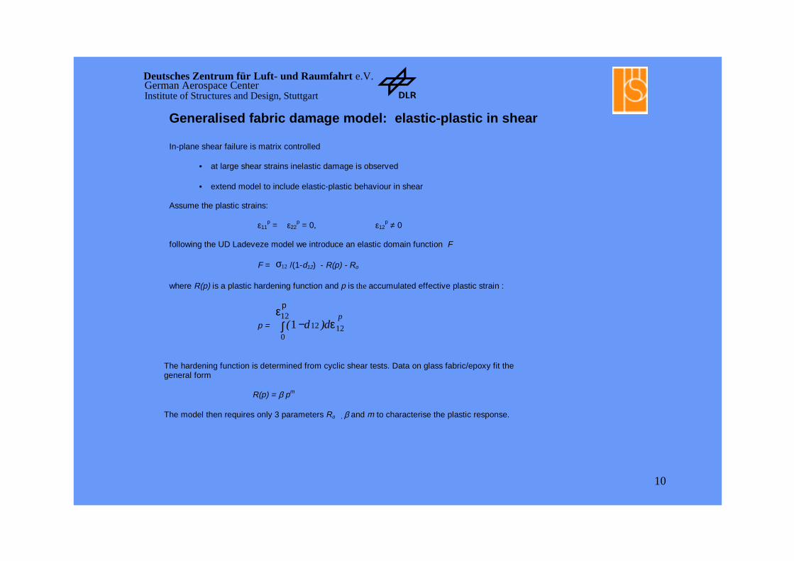
Generalised fabric damage model: elastic-plastic in shear
In-plane shear failure is matrix controlled
• at large shear strains inelastic damage is observed • extend model to include elastic-plastic behaviour in shear
Assume the plastic strains:
ε11p = ε22
p = 0, ε12p ≠ 0
following the UD Ladeveze model we introduce an elastic domain function F
F = 12σ /(1-d12) - R(p) - Ro
where R(p) is a plastic hardening function and p is the accumulated effective plastic strain :
p = ( )10
1212 12−∫
εε
p
d dp
The hardening function is determined from cyclic shear tests. Data on glass fabric/epoxy fit thegeneral form
R(p) = β pm
The model then requires only 3 parameters Ro , β and m to characterise the plastic response.

11
Deutsches Zentrum für Luft- und Raumfahrt e.V. German Aerospace CenterInstitute of Structures and Design, Stuttgart
Determination of fabric model parameters in shearGlass fabric/epoxy. cyclic shear stress-strain curve
0 0.02 0.04 0.06 0.08 0.1 0.12
Total shear strain e12
Sh
ear
stre
ss s
12 M
pa
e12pl e12el
Evolution eqn. - elastic shear
-0.1
0
0.1
0.2
0.3
0.4
0.5
0.6
0.7
0.8
sq rt Y12
d12
d12
Logarithmisch (d12)
R(p) : comparison test data and power law model
-100
0
100
200
300
400
500
600
700
-0.002 0 0.002 0.004 0.006 0.008 0.01 0.012 0.014 0.016
p
R(p
) s12/(1-d12)-Q0
R(p)
•--Elastic damage evolution curve
- cyclic shear stress-strain curves showsignificant inelasticstrains
- elastic evolution equation for d12 is nonlinear
- hardening function R(p) modelled by powerlaw
Cyclic shear stress-strain curveCyclic shear stress-strain curve for GF/epoxy
Plastic hardening function R(p)
12
Deutsches Zentrum für Luft- und Raumfahrt e.V. German Aerospace CenterInstitute of Structures and Design, Stuttgart
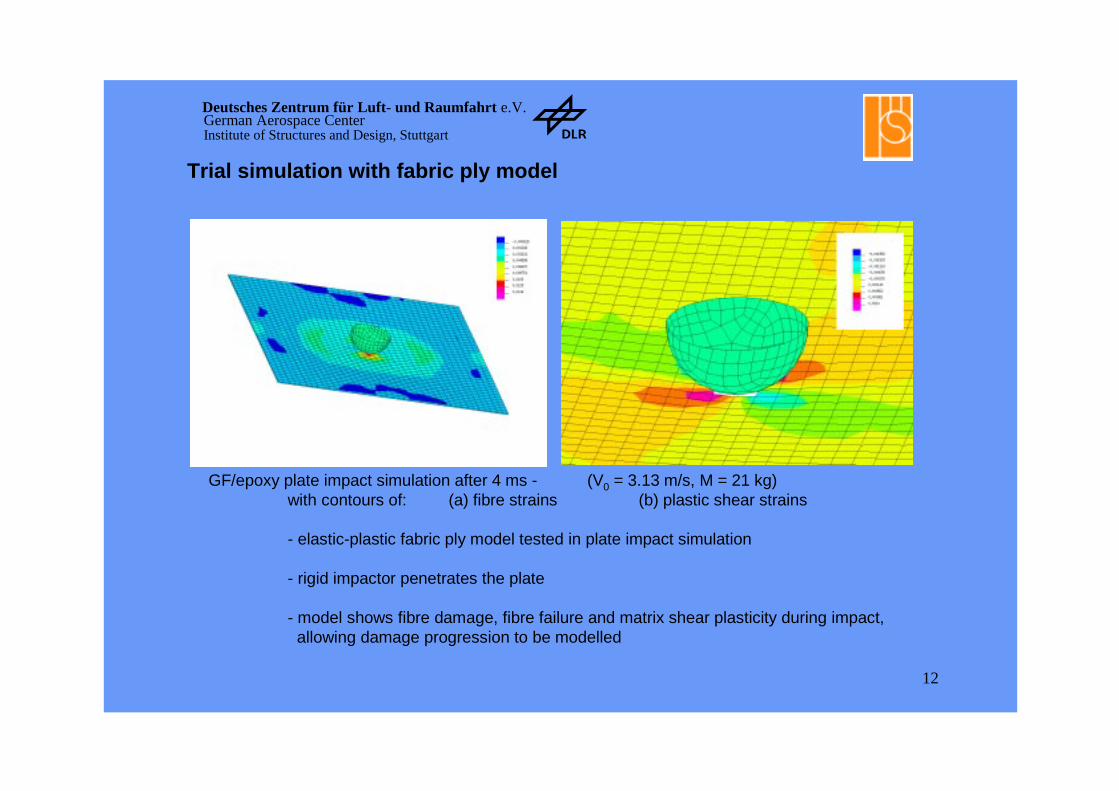
Trial simulation with fabric ply model
GF/epoxy plate impact simulation after 4 ms - (V0 = 3.13 m/s, M = 21 kg)with contours of: (a) fibre strains (b) plastic shear strains
- elastic-plastic fabric ply model tested in plate impact simulation
- rigid impactor penetrates the plate
- model shows fibre damage, fibre failure and matrix shear plasticity during impact,allowing damage progression to be modelled

13
Deutsches Zentrum für Luft- und Raumfahrt e.V. German Aerospace CenterInstitute of Structures and Design, Stuttgart
Rigid wall
22.5° section
15mm length
5mm trigger
0°90°+45°-45°....Matrixinterlaminar
Composite Tube Crushing using detailed solid modelling
• Fine solid model to individually model plies and interlaminar resin layers
• Bi-Phase damage model for fibre-matrix failure prediction
• Elasto-plastic damage model for resin interface elements

14
Deutsches Zentrum für Luft- und Raumfahrt e.V. German Aerospace CenterInstitute of Structures and Design, Stuttgart
Options for delamination modelling
Fine solid models
• CPU expensive
• Impractical for large-scale structures
Multilayered shell models
• Elements unable to represent interply shear deformation modes
• Inter-ply deformation energies must be calibrated using
questionable test programs
Stacked shell elements
• New approach that could resolve CPU problems and provide realistic
engineering solutions
• Each ply is modelled using one layer of shell elements
• The plies are ‘tied‘ using interface conditions that ‘damage‘
during delamination
15
Deutsches Zentrum für Luft- und Raumfahrt e.V. German Aerospace CenterInstitute of Structures and Design, Stuttgart
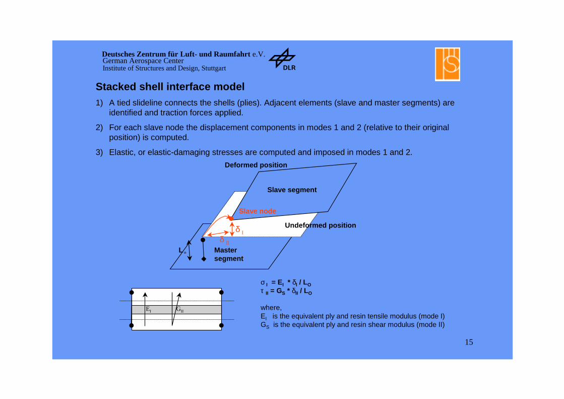
Master segment
Slave node
Slave segment
δ I
δ II
σ I = EI * δI / LOτ II = GS * δII / LO
where,EI is the equivalent ply and resin tensile modulus (mode I)GS is the equivalent ply and resin shear modulus (mode II)
EI GII
Undeformed position
Deformed position
L O
Stacked shell interface model1) A tied slideline connects the shells (plies). Adjacent elements (slave and master segments) are
identified and traction forces applied.
2) For each slave node the displacement components in modes 1 and 2 (relative to their original position) is computed.
3) Elastic, or elastic-damaging stresses are computed and imposed in modes 1 and 2.
16
Deutsches Zentrum für Luft- und Raumfahrt e.V. German Aerospace CenterInstitute of Structures and Design, Stuttgart
Area = GC(I,II)
δ (crack opening)
δ max
σmax
σ(s
tres
s)
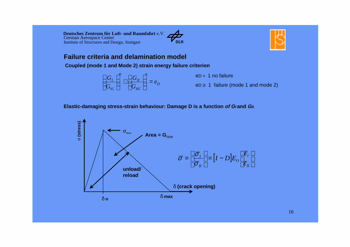
Coupled (mode 1 and Mode 2) strain energy failure criterion
D
n
IIC
II
m
IC
I eG
G
G
G =
+
[ ]
−=
=II
IO
II
I EDIεε
σσσ
Elastic-damaging stress-strain behaviour: Damage D is a function of GI and GII.
unload/reload
δ o
Failure criteria and delamination model
eD < 1 no failure
eD ≥ 1 failure (mode 1 and mode 2)

17
Deutsches Zentrum für Luft- und Raumfahrt e.V. German Aerospace CenterInstitute of Structures and Design, Stuttgart
Damaging normal stress versus crack opening displacement for the interply resin
Time history of crack opening force measured at free end
Example: Delamination (Mode 1) for a composite DCB test
Simulation of delamination (Mode 1)

18
Deutsches Zentrum für Luft- und Raumfahrt e.V. German Aerospace CenterInstitute of Structures and Design, Stuttgart
Conclusions and outlook
• FE simulations with ‘bi-phase’ model predict well observed failure modes of composite elements under crash and impact loads
– helicopter EA floor beam structures
– wing access panel under high velocity impact
• For complex crush and delamination failure modes, simulated loads and EA levels do not agree quantitatively with test results
– further improvements required in materials and numerical modelling
• Improved composites models under development in HICAS
– damage mechanics models for UD and fabric ply in-plane properties
– interlaminar failure models based on fracture mechanics
– inclusion of strain rate dependence
• First trials with code implementations in PAM-CRASH look promising
– fabric ply damage model implemented and tested
– stacked shell elements with slide lines tested in mode I failure
.
Acknowledgements:Acknowledgements: Some of the work presented here was developed in the EU project HICAS.The financial contribution from the CEC and technical input from the partners is acknowledged.