IMDD vs Coherent
67
IMDD vs Coherent Will Datacenter be the New Battleground? Summer Topicals 2020 Virtual Conference Tutorial TuA2.2 10:45AM – 11:30AM MDT 14 July 2020 Chris Cole
Transcript of IMDD vs Coherent

IMDD vs CoherentWill Datacenter be the New Battleground?
Summer Topicals 2020 Virtual Conference
Tutorial TuA2.2 10:45AM – 11:30AM MDT
14 July 2020
Chris Cole

IEEE Photonics Society Summer Topicals 2020 TuA2.2 14 July 2020 Chris Cole Luminous Computing2
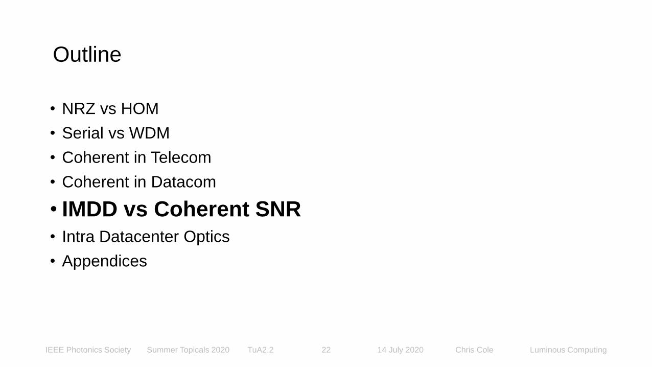
Outline
• NRZ vs HOM
• Serial vs WDM
• Coherent in Telecom
• Coherent in Datacom
• IMDD vs Coherent SNR
• Intra Datacenter Optics
• Appendices

IEEE Photonics Society Summer Topicals 2020 TuA2.2 14 July 2020 Chris Cole Luminous Computing3
Shannon-Hartley Theorem
C = B log2 (1 + S/N)
C ≜ Channel capacity
B ≜ Bandwidth
S ≜ Signal Power
N ≜ Noise Power
Guidance to increase C:
If B limited, use S/N to increase modulation order
If S/N limited, use B to increase Baud rate
C. Cole, “SMF PMD Modulation Observations”, 400 Gb/s Ethernet Task Force, IEEE 802.3 Plenary Session, Berlin, Germany, 10-12 March 2015cc

IEEE Photonics Society Summer Topicals 2020 TuA2.2 14 July 2020 Chris Cole Luminous Computing4
Cu C2C SerDes & SMF Client TRX S/N (BtB, no FEC)
SMF Client Loss (electrical dB)
Cu Chip-to-Chip Loss (max)
SMF client TRX:low S/Nhigh B
Shannon says: use NRZ
Cu C2C SerDes:high S/Nlow B
Shannon says: use HOM
HOM ≜ Higher Order Modulation

IEEE Photonics Society Summer Topicals 2020 TuA2.2 14 July 2020 Chris Cole Luminous Computing5
Ideal SMF Client System Model
• SMF client channel ideal
• (TX ∗ Channel ∗ RX) modelled as 4th order BT filter
• B = α bit-rate
• Ex. bit rate = 56Gb/s
ex. 1: α = 0.25 → B = 14GHz
ex. 2: α = 0.30 → B = 17GHz
Source TX Channel RX Slicer

IEEE Photonics Society Summer Topicals 2020 TuA2.2 14 July 2020 Chris Cole Luminous Computing6
Slicer Input Eyes of Ideal Noiseless SMF Client System
-1 -0.8 -0.6 -0.4 -0.2 0 0.2 0.4 0.6 0.8 1
-0.5
0
0.5
Time
Am
plitu
de
Eye Diagram
-1 -0.8 -0.6 -0.4 -0.2 0 0.2 0.4 0.6 0.8 1
-0.5
0
0.5
Time
Am
plitude
Eye Diagram
-1 -0.8 -0.6 -0.4 -0.2 0 0.2 0.4 0.6 0.8 1
-0.5
0
0.5
Time
Am
plitude
Eye Diagram
-1 -0.8 -0.6 -0.4 -0.2 0 0.2 0.4 0.6 0.8 1
-0.5
0
0.5
Time
Am
plit
ude
Eye Diagram
Ex. 1. α = 0.25 (14GHz)
NRZ VEC PAM4 VEC
NRZ PAM-4
Ex. 2. α = 0.30 (17GHz)
NRZ VEC < PAM4 VEC

IEEE Photonics Society Summer Topicals 2020 TuA2.2 14 July 2020 Chris Cole Luminous Computing7
Vertical Eye Closure at Slicer Input w/ Noise Normalization
NRZ
PAM-4 (middle eye)
SMF client TRX S/N

IEEE Photonics Society Summer Topicals 2020 TuA2.2 14 July 2020 Chris Cole Luminous Computing8
IEEE Modulation Choice for 50Gb/s and Faster Rates
• Optics is the tail on the IC industry dog
• 50G PAM4 ASIC SerDes was first developed for the Cu channel
• IC Vendors wanted to maximize their ADC and DSP investment
• IC dog wagged the optics tail
• IEEE ignored Shannon
• PAM4 standardized for 50G and 100G Ethernet optical lane rates
• 200G (4x50G PAM4) FR4 will soon ship in the millions
• Optics & electronics today easily support 50G NRZ
• Extra cost and power of 50G PAM4 ADC, DSP, SNR locked-in forever

IEEE Photonics Society Summer Topicals 2020 TuA2.2 14 July 2020 Chris Cole Luminous Computing9
Outline
• NRZ vs HOM
• Serial vs WDM
• Coherent in Telecom
• Coherent in Datacom
• IMDD vs Coherent SNR
• Intra Datacenter Optics
• Appendices
IEEE Photonics Society Summer Topicals 2020 TuA2.2 14 July 2020 Chris Cole Luminous Computing10
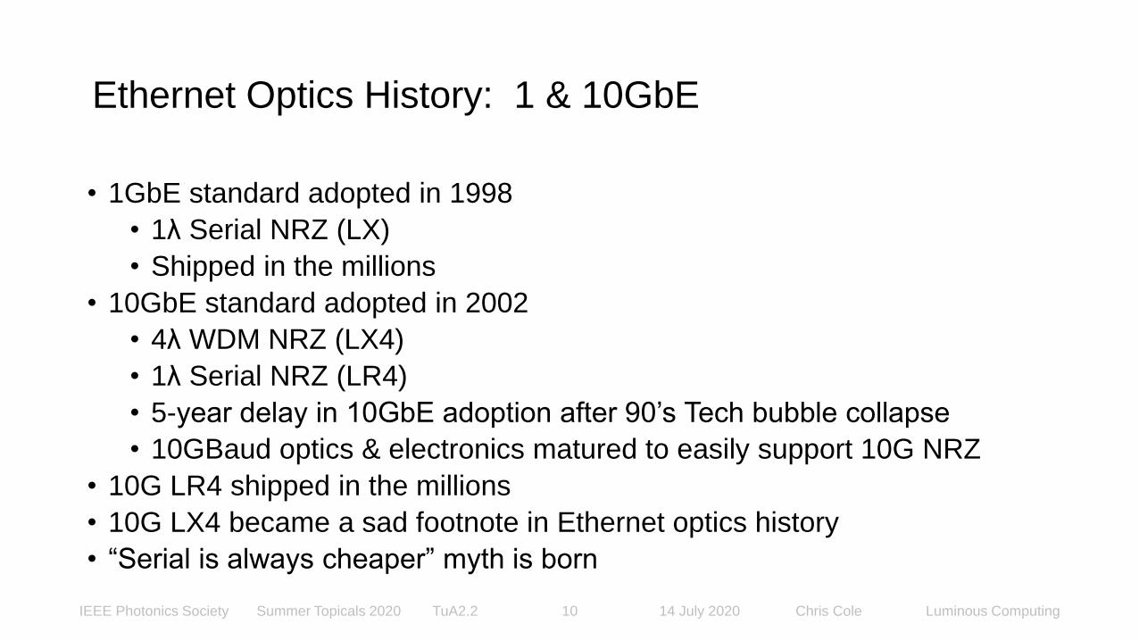
Ethernet Optics History: 1 & 10GbE
• 1GbE standard adopted in 1998
• 1λ Serial NRZ (LX)
• Shipped in the millions
• 10GbE standard adopted in 2002
• 4λ WDM NRZ (LX4)
• 1λ Serial NRZ (LR4)
• 5-year delay in 10GbE adoption after 90’s Tech bubble collapse
• 10GBaud optics & electronics matured to easily support 10G NRZ
• 10G LR4 shipped in the millions
• 10G LX4 became a sad footnote in Ethernet optics history
• “Serial is always cheaper” myth is born

IEEE Photonics Society Summer Topicals 2020 TuA2.2 14 July 2020 Chris Cole Luminous Computing11
Ethernet Optics History: 40GbE
• 40GbE standard adopted in 2010
• “Serial is always cheaper” myth well established
• Fierce debate in the IEEE between:
• 4λ WDM NRZ (LR4) vs.
• 1λ Serial NRZ (FR)
• IEEE split the baby, adopted both
• 40G LR4 shipped in the millions
• 40G FR became a sad footnote in Ethernet optics history
IEEE Photonics Society Summer Topicals 2020 TuA2.2 14 July 2020 Chris Cole Luminous Computing12
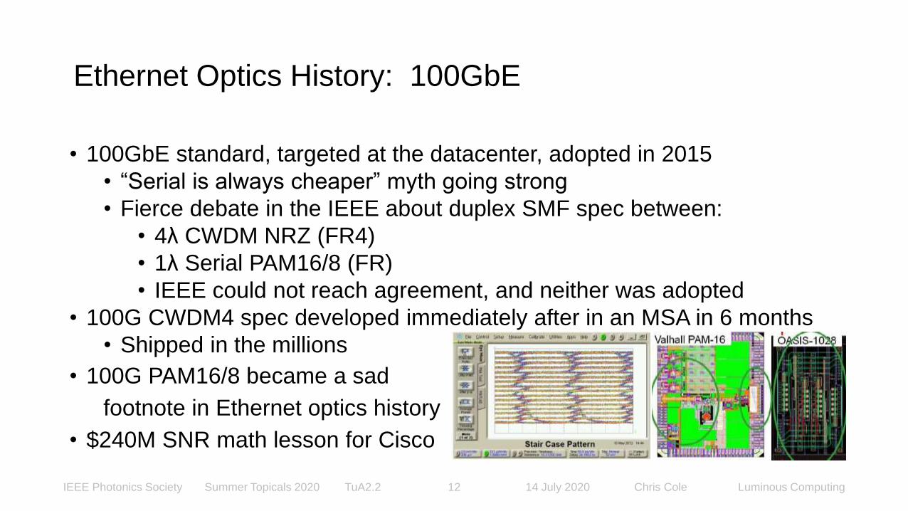
Ethernet Optics History: 100GbE
• 100GbE standard, targeted at the datacenter, adopted in 2015
• “Serial is always cheaper” myth going strong
• Fierce debate in the IEEE about duplex SMF spec between:
• 4λ CWDM NRZ (FR4)
• 1λ Serial PAM16/8 (FR)
• IEEE could not reach agreement, and neither was adopted
• 100G CWDM4 spec developed immediately after in an MSA in 6 months
• Shipped in the millions
• 100G PAM16/8 became a sad
footnote in Ethernet optics history
• $240M SNR math lesson for Cisco

IEEE Photonics Society Summer Topicals 2020 TuA2.2 14 July 2020 Chris Cole Luminous Computing13
Ethernet Optics History: 400GbE
• 400GbE standard adopted in 2017
• “Serial is always cheaper” myth unwavering
• Fierce debate in the IEEE between:
• 2λ*50G WDM for 100G FR2 and 8λ*50G LWDM 400G LR8
• 1λ*100G Serial for 100G FR and 400G PSM DR4
• IEEE split the baby, adopted 400G LR8 and DR4, but no 100G FR2
• 400G 8λ*50G LWDM LR8 shipped in low volume into early Telecom apps
• 400G 4λ*100G CWDM FR4 standardized soon afterwards

IEEE Photonics Society Summer Topicals 2020 TuA2.2 14 July 2020 Chris Cole Luminous Computing14
Ethernet Optics History: 400GbE (2)
• Ethernet optics sad story 1: no Web2.0 deployment of 400GbE
• Huge industry R&D investment into 1st Gen 400GbE DR4 & FR4 with no ROI
• 2nd Gen 400GbE will start shipping in volume in 2023 or later when Ethernet switches ship with 100G I/O
• Ethernet optics sad story 2: no low-cost, low-power 2λ 100GbE optics matched to today’s Ethernet switches with 50G I/O, forcing shipment of:
• 4λ 100G CWDM4 with 1:2 reverse gearbox (most Web2.0s), or
• 1λ 100G FR with with 2:1 forward gearbox (Amazon mainly)
• Either way, significant cost and power added to 100G Ethernet optical links

IEEE Photonics Society Summer Topicals 2020 TuA2.2 14 July 2020 Chris Cole Luminous Computing15
Outline
• NRZ vs HOM
• Serial vs WDM
• Coherent in Telecom
• Coherent in Datacom
• IMDD vs Coherent SNR
• Intra Datacenter Optics
• Appendices

IEEE Photonics Society Summer Topicals 2020 TuA2.2 14 July 2020 Chris Cole Luminous Computing16
G.652 SMF DWDM Transport C-band Spec Limits
• Loss
• nom, max: 0.2, 0.28dB/km
• IF link SNR was only determined by link loss
• Coherent SNR 2x IMDD SNR, in dB
• Coherent reach 2x IMDD reach, i.e. half the amplifier cost
• Bandwidth (B)
• Spectral Efficiency is key metric because of fiber deployment cost
• G.694.1 channel bandwidths: 25 to 100GHz
• Coherent has 4 orthogonal channels: I, Q, TE, TM
• Shannon says: If B limited, use S/N to increase modulation order

IEEE Photonics Society Summer Topicals 2020 TuA2.2 14 July 2020 Chris Cole Luminous Computing17
G.652 SMF DWDM Transport C-band Spec Limits (2)
• Chromatic Dispersion (CD)
• nom, max: 17, 20ps/nm-km
• CD penalty variable with link reach
• IMDD Fixed EQ: unique CDF length for each link
• Coherent adaptive EQ: common for all links
• Polarization Mode Dispersion Q (PMDQ)
• A&C nom: 0.5ps/km
• B&D nom: 0.2ps/km
• DGD is important over long reaches
• Coherent adaptive EQ tracks polarization

IEEE Photonics Society Summer Topicals 2020 TuA2.2 14 July 2020 Chris Cole Luminous Computing18
Transport Cost vs Time
Optical Networks Forecast: 2018 – 2023, Jan 2019 Representative cost of optical transport capacity over time and transponder generations based on historical average sales price (ASP) of DWDM line card data from Ovum.
10G - 40G: IMDD
100G - 800G: Coherent
“A straight line willcontinue indefinitelyas a straight line”

IEEE Photonics Society Summer Topicals 2020 TuA2.2 14 July 2020 Chris Cole Luminous Computing19
Outline
• NRZ vs HOM
• Serial vs WDM
• Coherent in Telecom
• Coherent in Datacom
• IMDD vs Coherent SNR
• Intra Datacenter Optics
• Appendices

IEEE Photonics Society Summer Topicals 2020 TuA2.2 14 July 2020 Chris Cole Luminous Computing20
G.652 1km SMF CWDM4 O-band Spec Limits
• Loss
• max: 0.47dB
• Connectors and other passives determine link loss
• Nom link loss budget: 4dB
• SMF loss is not important
• Bandwidth (B)
• 4 wavelength band: 10THz
• 1 wavelength channel: 800GHz
• Shannon says: If S/N limited, use B to increase Baud rate
• SMF bandwidth is not important

IEEE Photonics Society Summer Topicals 2020 TuA2.2 14 July 2020 Chris Cole Luminous Computing21
G.652 1km SMF CWDM4 O-band Spec Limits (2)
• Chromatic Dispersion (CD)
• min: -6ps/nm
• max: 3ps/nm
• SMF CD penalty is not important
• Polarization Mode Dispersion Q (PDMQ)
• A&C nom: 0.5ps
• B&D nom: 0.2ps
• SMF DGD penalty is not important
IEEE Photonics Society Summer Topicals 2020 TuA2.2 14 July 2020 Chris Cole Luminous Computing22
Outline
• NRZ vs HOM
• Serial vs WDM
• Coherent in Telecom
• Coherent in Datacom
• IMDD vs Coherent SNR
• Intra Datacenter Optics
• Appendices

IEEE Photonics Society Summer Topicals 2020 TuA2.2 14 July 2020 Chris Cole Luminous Computing23
pIN-TX = 4 p0 pRX = αSMF pTX
pTX = αTX αAOP pIN-TX pPD = αRX pRX / 4
iSIG = αAVG rPD pPD iN = αN i0 √BW
√snr = αAVG αRX αSMF αTX αAOP rPD p0 / (αN i0 √BW)
C. Cole, “Inside the Datacenter is not yet a Nail for the Coherent Hammer”, WS05, Data Centers 1, Session 1, ECOC 2018, Rome, Italy, 23 Sep. 2018.
Direct Detection (DD) Signal Path

IEEE Photonics Society Summer Topicals 2020 TuA2.2 14 July 2020 Chris Cole Luminous Computing24
pIN-TX = 4 αLS αTEC p0 pRX = αSMF αTX
pTX = αG αTX αAOP pIN-TX pPD-RX = αRX pRX / 4
pIN-LO = 4 (1 - αLS) αTEC p0 pLO = pIN-LO pPD-LO = αLO pLO / 4
iSIG = αAVG rPD 2 √(pPD-RX pPD-LO) iN = αN i0 √BW
√snr = αAVG αRX √(αSMF αG αTX αAOP) αTEC rPD p0 / (αN i0 √BW)
Coherent (CH) Signal Path

IEEE Photonics Society Summer Topicals 2020 TuA2.2 14 July 2020 Chris Cole Luminous Computing25
Optical ∆SNRDD-CH = SNRDD - SNRCH dB
A ≜ loss in optical -dB
A = -10log10(α)
∆SNRDD-CH = SNRDD - SNRCH = 10log10(snrDD / snrCH)
∆SNRDD-CH / 2 = - (ΑAOP-DD + ΑTX-DD + ΑSMF)
+ (ΑAOP-CH + ΑTX-CH + AG + ΑSMF) / 2 + ΑTEC
- (ΑAVG-DD + ΑRX-DD - AN-DD)
+ (ΑAVG-CH + ΑRX-CH - AN-CH)
ATXT-DD = ΑAOP-DD + ΑTX-DD ARXT-DD = ΑAVG-DD + ΑRX-DD - AN-DD
ATXT-CH = ΑAOP-CH + ΑTX-CH + AG + 2ΑTEC ARXT-CH = ΑAVG-CH + ΑRX-CH - AN-CH
∆SNRDD-CH = (ATXT-CH + ASMF + 2ARXT-CH) - 2(ATXT-DD + ASMF + ARXT-DD)

IEEE Photonics Society Summer Topicals 2020 TuA2.2 14 July 2020 Chris Cole Luminous Computing26
Optical ∆SNRDD-CH dB Examples
• Equal laser input AOP (TEC ignored):
∆SNRDD-CH = ((ATXT-CH + ASMF) - 2(ATXT-DD + ASMF)) + 2(ARXT-CH - ARXT-DD)
• 100G EML NRZ CWDM4 IMDD vs 100G SiPIC QPSK Coherent
• Ex.1: 4dB Link Loss (2km, typical intra datacenter)
∆SNRDD-CH = ((17 + 4) - 2( 5 + 4)) + 2( 4 - 2) = 7dB
• Ex.2: 11dB Link Loss (20km, or 2km & one 7dB loss optical switch)
∆SNRDD-CH = ((17 + 11) - 2( 5 + 11)) + 2( 4 - 2) = 0
• Ex.2: 18dB Link Loss (40km, or 2km & two 7dB loss optical switches)
∆SNRDD-CH = ((17 + 18) - 2( 5 + 18)) + 2( 4 - 2) = -7dB

IEEE Photonics Society Summer Topicals 2020 TuA2.2 14 July 2020 Chris Cole Luminous Computing27
Outline
• NRZ vs HOM
• Serial vs WDM
• Coherent in Telecom
• Coherent in Datacom
• IMDD vs Coherent SNR
• Intra Datacenter Optics
• Appendices

IEEE Photonics Society Summer Topicals 2020 TuA2.2 14 July 2020 Chris Cole Luminous Computing28
Intra Datacenter Optics Requirements
• What’s important?
• Cheap laser(s)
• Cheap SNR (low loss components)
• Cheap assembly and packaging
• Cheap testing
• What does Coherent offer?
• Expensive Laser
• High loss components
• Best case comparable packaging cost to IMDD
• Complex testing

IEEE Photonics Society Summer Topicals 2020 TuA2.2 14 July 2020 Chris Cole Luminous Computing29
TX Modulator Size Comparison
• IMDD InP EML length:
• 400 - 500um (EA 120um)
• Coherent Si MZM length:
• 2 - 4mm
• 4 channel Coherent to IMDD TX area ratio: Teriphic project, 4x100G PAM4 EML TX
• 10 - 20x

IEEE Photonics Society Summer Topicals 2020 TuA2.2 14 July 2020 Chris Cole Luminous Computing30
Intra Datacenter Optics Today: Pluggable
• Characteristics
• $1 - $2/Gb
• ~30pJ/bit
• IMDD DML or EML uncooled TX
• 4λ CWDM NRZ or PAM4
• Link budget: 4dB
• IMDD vs. Coherent SNR, equal laser DC Power (TEC included):
100G EML NRZ CWDM4 IMDD vs 100G SiPIC QPSK Coherent
∆SNRDD-CH = 11.5dB
(same result for PAM4 IMDD vs QAM16 Coherent)

IEEE Photonics Society Summer Topicals 2020 TuA2.2 14 July 2020 Chris Cole Luminous Computing31
Intra Datacenter Optics Tomorrow: Co-packaged
• Requirements
• Co-packaged with Ethernet Switch ASIC
• 256 - 512 data lanes
• <$1/Gb
• <10pJ/bit
• Link budget: 4dB
• IMDD vs. Coherent SNR, equal laser DC Power (TEC included):
100G SiPIC NRZ CWDM4 IMDD vs 100G SiPIC QPSK Coherent
∆SNRDD-CH = 1.5dB
(same result for PAM4 IMDD vs QAM16 Coherent)

IEEE Photonics Society Summer Topicals 2020 TuA2.2 14 July 2020 Chris Cole Luminous Computing32
Summary
• Coherent advantages in Transport are unimportant in Intra Datacenter
• Coherent indefinitely locks in the cost and power of ADCs and DSPs
• This is what PAM4 did for >100G Ethernet optics
• Good for IC vendors, bad for everyone else as optics improve
• “Serial is always cheaper” is a myth for leading data rates
• 10GbE was the last time it was true
• 1λ Coherent is higher cost and power than 4λ IMDD
• Coherent does not reduce the cost and power of short reach optics
• There is no IMDD vs Coherent competition for Intra Datacenter links
• Coherent is not even on the battleground

IEEE Photonics Society Summer Topicals 2020 TuA2.2 14 July 2020 Chris Cole Luminous Computing33
IMDD vs Coherent
Thank You
www.ieee-sum.org

IEEE Photonics Society Summer Topicals 2020 TuA2.2 14 July 2020 Chris Cole Luminous Computing34
Outline
• NRZ vs HOM
• Serial vs WDM
• Coherent in Telecom
• Coherent in Datacom
• IMDD vs Coherent SNR
• Intra Datacenter Optics
• Appendix 1

IEEE Photonics Society Summer Topicals 2020 TuA2.2 14 July 2020 Chris Cole Luminous Computing35
Direct Detection (DD) Signal Path Variables
p0 ≜ Input POP (Peak Optical Power) reference
pIN-TX ≜ TX input POP = AOP (Average OP) if CW
αAOP ≜ TX POP to AOP modulation loss vs. er (extinction ratio)
αTX ≜ TX path intrinsic loss at modulator bias point
pTX ≜ TX total output AOP
αSMF ≜ Link total power loss (connectors, SMF, other passives)
pRX ≜ RX total input AOP
αRX ≜ RX path intrinsic loss
pPD ≜ RX PD input AOP
rPD ≜ RX PD responsivity
αAVG ≜ PD AOP to average electrical signal power loss vs. er

IEEE Photonics Society Summer Topicals 2020 TuA2.2 14 July 2020 Chris Cole Luminous Computing36
Direct Detection (DD) SNR
iSIG ≜ RX PD signal current
iSIG = αAVG rPD pPD = αAVG αRX αSMF αTX αAOP rPD p0
iN ≜ RX input referred noise current; all sources
i0 ≜ RX input noise current density reference
αN ≜ RX input noise current loss vs. i0BW ≜ RX input noise bandwidth
iN = αN i0 √BW
snr = (iSIG / iN)2
√snr = αAVG αRX αSMF αTX αAOP rPD p0 / (αN i0 √BW)

IEEE Photonics Society Summer Topicals 2020 TuA2.2 14 July 2020 Chris Cole Luminous Computing37
Coherent (CH) Signal Path Variables
p0 ≜ Input POP (Peak Optical Power) reference
αTEC ≜ Input POP loss due to laser TEC current
αLS ≜ TX input POP loss due to (1- αLS) LO (Local Oscillator) input split
pIN-TX ≜ TX input POP = AOP since CW
αAOP ≜ TX POP to AOP modulation loss vs. MD (mod. drive)
αTX ≜ TX path intrinsic loss at modulator bias point
αG ≜ TX optical gain (αG = 1 if no amplification)
pTX ≜ TX total output AOP
αSMF ≜ Link total power loss (connectors, SMF, other passives)

IEEE Photonics Society Summer Topicals 2020 TuA2.2 14 July 2020 Chris Cole Luminous Computing38
Coherent (CH) Signal Path Variables, cont.
pRX ≜ RX total input AOP
pLO ≜ RX LO input AOP
Ф(t) ≜ Phase angle between pRX and pLO electric fields
αRX ≜ RX SIG path intrinsic loss
αLO ≜ RX LO path intrinsic loss
pPD ≜ RX PD input AOP
rPD ≜ RX PD responsivity
αAVG ≜ PD AOP to average electrical signal power loss vs. MD

IEEE Photonics Society Summer Topicals 2020 TuA2.2 14 July 2020 Chris Cole Luminous Computing39
Coherent Signal Addition
Optical signals, with same polarization state, add in the electric field domain
ELO / √Z ≜ √pLO
ERX / √Z = cos Ф(t) √pRX + j sin Ф(t) √pRX
EPD / √Z = √pLO + cos Ф(t) √pRX + j sin Ф(t) √pRX
PPD = (√pLO + cos Ф(t) √pRX)2 + (sin Ф(t) √pRX)2
= pLO + 2 √pLO √pRX cos Ф(t) + pRX
pRX << 2 √pLO √pRX cos Ф(t)
pLO RIN << 2 √pLO √pRX cos Ф(t)
pPD = 2 √(pLO pRX) cos Ф(t)
IEEE Photonics Society Summer Topicals 2020 TuA2.2 14 July 2020 Chris Cole Luminous Computing40
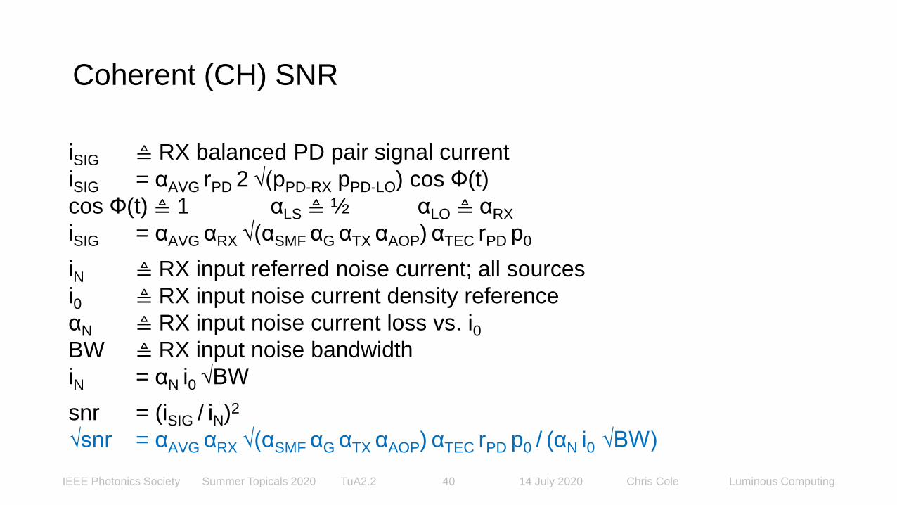
Coherent (CH) SNR
iSIG ≜ RX balanced PD pair signal current
iSIG = αAVG rPD 2 √(pPD-RX pPD-LO) cos Ф(t)
cos Ф(t) ≜ 1 αLS ≜ ½ αLO ≜ αRX
iSIG = αAVG αRX √(αSMF αG αTX αAOP) αTEC rPD p0
iN ≜ RX input referred noise current; all sources
i0 ≜ RX input noise current density reference
αN ≜ RX input noise current loss vs. i0BW ≜ RX input noise bandwidth
iN = αN i0 √BW
snr = (iSIG / iN)2
√snr = αAVG αRX √(αSMF αG αTX αAOP) αTEC rPD p0 / (αN i0 √BW)

IEEE Photonics Society Summer Topicals 2020 TuA2.2 14 July 2020 Chris Cole Luminous Computing41
Ratio DD SNR to CH SNR: √(snrDD / snrCH)
√snrDD = αAVG αRX αSMF αTX αAOP rPD p0 / (αN i0 √BW)
√snrCH = αAVG αRX √(αSMF αG αTX αAOP) αTEC rPD p0 / (αN i0 √BW)
rPD-DD ≜ rPD-CH
BWDD ≜ BWCH
√(snrDD / snrCH) = αAVG-DD αRX-DD αSMF αTX-DD αAOP-DD αN-CH
/ αAVG-CH αRX-CH √(αSMF αG αTX-CH αAOP-CH) αTEC αN-DD

IEEE Photonics Society Summer Topicals 2020 TuA2.2 14 July 2020 Chris Cole Luminous Computing42
Optical ∆SNRDD-CH = SNRDD - SNRCH dB
A ≜ loss in optical -dB
A = -10log10(α)
∆SNRDD-CH = SNRDD - SNRCH = 10log10(snrDD / snrCH)
∆SNRDD-CH / 2 = - (ΑAOP-DD + ΑTX-DD + ΑSMF)
+ (ΑAOP-CH + ΑTX-CH + AG + ΑSMF) / 2 + ΑTEC
- (ΑAVG-DD + ΑRX-DD - AN-DD)
+ (ΑAVG-CH + ΑRX-CH - AN-CH)
ATX-T-DD = ΑAOP-DD + ΑTX-DD ARX-T-DD = ΑAVG-DD + ΑRX-DD - AN-DD
ATX-T-CH = ΑAOP-CH + ΑTX-CH + AG + 2ΑTEC ARX-T-CH = ΑAVG-CH + ΑRX-CH - AN-CH
∆SNRDD-CH = (ATX-T-CH + ASMF + 2ARX-T-CH) - 2(ATX-T-DD + ASMF - ARX-T-DD)

IEEE Photonics Society Summer Topicals 2020 TuA2.2 14 July 2020 Chris Cole Luminous Computing43
Outline
• NRZ vs HOM
• Serial vs WDM
• Coherent in Telecom
• Coherent in Datacom
• IMDD vs Coherent SNR
• Intra Datacenter Optics
• Appendix 2
IEEE Photonics Society Summer Topicals 2020 TuA2.2 14 July 2020 Chris Cole Luminous Computing44
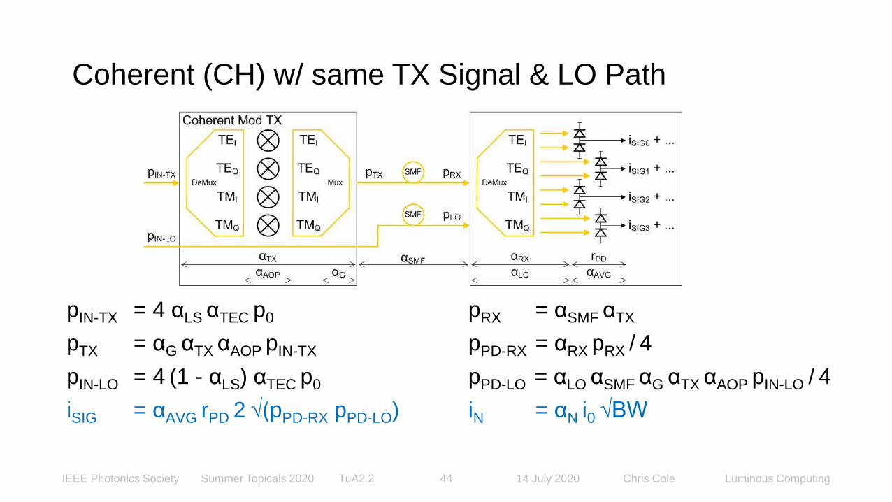
pIN-TX = 4 αLS αTEC p0 pRX = αSMF αTX
pTX = αG αTX αAOP pIN-TX pPD-RX = αRX pRX / 4
pIN-LO = 4 (1 - αLS) αTEC p0 pPD-LO = αLO αSMF αG αTX αAOP pIN-LO / 4
iSIG = αAVG rPD 2 √(pPD-RX pPD-LO) iN = αN i0 √BW
Coherent (CH) w/ same TX Signal & LO Path

IEEE Photonics Society Summer Topicals 2020 TuA2.2 14 July 2020 Chris Cole Luminous Computing45
Coherent (CH) RX Signal w/ same TX Signal & LO Path
iSIG ≜ RX balanced PD pair signal current
iSIG = αAVG rPD 2 √(pPD-RX pPD-LO)
αLS ≜ ½ αLO ≜ αRX
iSIG = αAVG αRX αSMF αG αTX αAOP αTEC rPD p0
Equal DD and CH total input AOP condition:
pIN-DD-TX ≜ pIN-CH-TX + pIN-CH-LO
iDD-SIG = iCH-SIG
When the LO is remote, i.e. it’s a RO, there is no Coherent signal gain!
Same TX Signal and LO Path analysis approach proposed by Mike Frankel, Ciena, 18 Jan 2018.
IEEE Photonics Society Summer Topicals 2020 TuA2.2 14 July 2020 Chris Cole Luminous Computing46
Outline
• NRZ vs HOM
• Serial vs WDM
• Coherent in Telecom
• Coherent in Datacom
• IMDD vs Coherent SNR
• Intra Datacenter Optics
• Appendix 3

IEEE Photonics Society Summer Topicals 2020 TuA2.2 14 July 2020 Chris Cole Luminous Computing47
∆SNRDD-CH / 2 =
- ΑAOP-DD + ΑAOP-CH / 2 // TX
- ΑTX-DD + ΑTX-CH / 2 // TX
- (- ΑG / 2) + ΑTEC // TX Scenario
- ΑSMF + ΑSMF / 2 // Link
- ΑRX-DD + ΑRX-CH // RX
- ΑAVG-DD + ΑAVG-CH // RX
- (- AN-DD) + (- AN-CH) // RX
∆SNRDD-CH = SNRDD - SNRCH Examples
IEEE Photonics Society Summer Topicals 2020 TuA2.2 14 July 2020 Chris Cole Luminous Computing48
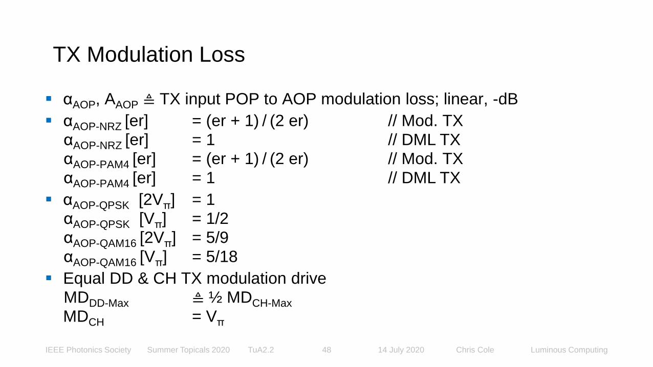
▪ αAOP, AAOP ≜ TX input POP to AOP modulation loss; linear, -dB
▪ αAOP-NRZ [er] = (er + 1) / (2 er) // Mod. TXαAOP-NRZ [er] = 1 // DML TXαAOP-PAM4 [er] = (er + 1) / (2 er) // Mod. TXαAOP-PAM4 [er] = 1 // DML TX
▪ αAOP-QPSK [2Vπ] = 1αAOP-QPSK [Vπ] = 1/2αAOP-QAM16 [2Vπ] = 5/9αAOP-QAM16 [Vπ] = 5/18
▪ Equal DD & CH TX modulation driveMDDD-Max ≜ ½ MDCH-Max
MDCH = Vπ
TX Modulation Loss

IEEE Photonics Society Summer Topicals 2020 TuA2.2 14 July 2020 Chris Cole Luminous Computing49
mod. loss
variable
ER
dB
DD mod. loss value -dB DD DM loss value -dB
NRZ PAM4 NRZ PAM4
AAOP-DD
∞ 3.0 3.0 0.0 0.0
7 2.2 2.2 0.0 0.0
4.8 1.8 1.8 0.0 0.0
mod. loss
variableMD
CH loss value -dB CH loss value -dB / 2
QPSK QAM16 QPSK QAM16
AAOP-CH
2Vπ 0.0 2.6 0.0 1.3
Vπ 3.0 5.6 1.5 2.8
▪ AAOP ≜ TX input POP to AOP modulation loss, -dB
TX Modulation Loss Values

IEEE Photonics Society Summer Topicals 2020 TuA2.2 14 July 2020 Chris Cole Luminous Computing50
▪ ATX ≜ TX path intrinsic loss, -dB
Ex.
#Implementation
DD loss value
-dB
CH loss value
-dB
ATX-DD ATX-CH
1 Ideal TX & RX, no loss 0 0
2DD CWDM4 TFF DML TX, RX
CH SiP4 14
3DD CWDM4 TFF EML TX, RX
CH SiP (ECOC’18 WS Example)5 14
4DD PSM4 SiP TX & RX
CH SiP6 14
5 DD CWDM4 SiP TX & RX, CH SiP 8 14
TX Signal Path Intrinsic Loss Values

IEEE Photonics Society Summer Topicals 2020 TuA2.2 14 July 2020 Chris Cole Luminous Computing51
▪ αTEC, ATEC ≜ TXCH input POP loss, laser TEC current; linear, -dB
▪ αG, AG ≜ TXCH optical gain
ΑG TXCH optical gain = - ΑG TXDD optical loss in ∆SNRDD-CH table
▪ Scenario 1: equal laser DC power (40% efficient CH TEC)
iLaser-bias-DD ≜ iLaser-bias-CH + iLaser-TEC-CH
αTEC ≜ 0.4
αG ≜ 1
▪ Scenario 2: equal TX & LO total input POP (no CH TEC)
pIN-TX-DD ≜ pIN-TX-CH + pIN-LO-CH
αTEC ≜ 1
αG ≜ 1
TX Scenarios

IEEE Photonics Society Summer Topicals 2020 TuA2.2 14 July 2020 Chris Cole Luminous Computing52
▪ Scenario 3: equal TX total output AOP (no DC power limit)
pTX-DD ≜ pTX-CH
A TX-DD + AAOP-DD = AG + ATX-CH + AAOP-CH + ALS + ATEC
αTEC ≜ 1
ATEC = 0
αLS ≜ 1/2
ALS = 3
- AG / 2 = ((ATX-CH + AAOP-CH + 3) - (ATX-DD + AAOP-DD)) / 2
TX Scenarios, cont.
IEEE Photonics Society Summer Topicals 2020 TuA2.2 14 July 2020 Chris Cole Luminous Computing53
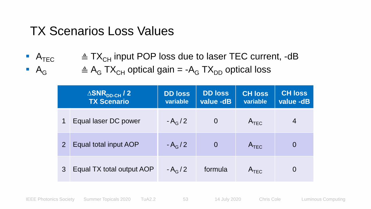
∆SNRDD-CH / 2
TX ScenarioDD lossvariable
DD loss
value -dBCH lossvariable
CH loss
value -dB
1 Equal laser DC power - ΑG / 2 0 ΑTEC 4
2 Equal total input AOP - ΑG / 2 0 ΑTEC 0
3 Equal TX total output AOP - ΑG / 2 formula ΑTEC 0
▪ ATEC ≜ TXCH input POP loss due to laser TEC current, -dB
▪ AG ≜ AG TXCH optical gain = -AG TXDD optical loss
TX Scenarios Loss Values

IEEE Photonics Society Summer Topicals 2020 TuA2.2 14 July 2020 Chris Cole Luminous Computing54
▪ ASMF ≜ Link total power loss (connectors, SMF, other passives), -dB
▪ Standard datacenter link loss budget
ASMF ≜ 4
DD loss
value -dB
CH loss
value -dB
ASMF ASMF / 2
4.0 2.0
Link Loss Values

IEEE Photonics Society Summer Topicals 2020 TuA2.2 14 July 2020 Chris Cole Luminous Computing55
▪ ARX ≜ RX path intrinsic loss, -dB
▪ ALO ≜ RX LO path intrinsic loss, -dB: ALO-CH ≜ ARX-CH
Ex.
#Implementation
DD loss value
-dB
CH loss value
-dB
ARX-DD ARX-CH
1 Ideal TX & RX, no loss 0 0
2DD CWDM4 TFF DML TX, RX
CH SiP2 4
3DD CWDM4 TFF EML TX, RX
CH SiP (ECOC’18 WS Example)2 4
4DD PSM4 SiP TX & RX
CH SiP2 4
5 DD CWDM4 SiP TX & RX, CH SiP 4 4
RX Signal Path Intrinsic Loss Values

IEEE Photonics Society Summer Topicals 2020 TuA2.2 14 July 2020 Chris Cole Luminous Computing56
▪ αAVG, AAVG ≜ RX PD AOP to average electrical signal power loss; linear, -dB
▪ αLS ≜ TX input POP loss due to (1- αLS) split with LO input
▪ αAVG-NRZ [er] = (er – 1) / (er + 1)
αAVG-PAM4 [er] = √(5/9) (er – 1) / (er + 1)
▪ αAVG-QPSK [2Vπ] = 1
αAVG-QPSK [Vπ] = 1
αAVG-QAM16 [2Vπ] = 1
αAVG-QAM16 [Vπ] = 1
▪ Equal DD & CH TX modulation drive
MDDD-Max ≜ ½ MDCH-Max
MDCH = Vπ
RX Modulation Loss

IEEE Photonics Society Summer Topicals 2020 TuA2.2 14 July 2020 Chris Cole Luminous Computing57
Mod. loss
variable
ER
dB
DD Mod. loss value -dB DD DM loss value -dB
NRZ PAM4 NRZ PAM4
AAVG-DD
∞ 0.0 1.3 0.0 1.3
7 1.8 3.0 1.8 3.0
4.8 3.0 4.3 3.0 4.3
▪ AAVG ≜ RX PD AOP to average electrical signal power loss, -dB
Mod. loss
variableMD
CH loss value -dB
QPSK QAM16
AAVG-CH
2Vπ 0.0 0.0
Vπ 0.0 0.0
RX Modulation Loss Values

IEEE Photonics Society Summer Topicals 2020 TuA2.2 14 July 2020 Chris Cole Luminous Computing58
▪ αALS, AALS ≜ Unequal SIG/LO split αLS ≠ ½ loss; linear, -dBαALS = 2 √(αLS (1 - αLS))αLS ≜ 1/2AALS = 0αLS ≜ 2/3AALS = 0.3
▪ A’AVG-CH = AAVG-CH + AALS
mod. loss
variableMD
CH loss value -dB
αLS = 1/2 αLS = 2/3
QPSK QAM16 QPSK QAM16
A’AVG-CH
2Vπ 0.0 0.0 0.3 0.3
Vπ 0.0 0.0 0.3 0.3
Coherent Unequal SIG/LO Split Loss

IEEE Photonics Society Summer Topicals 2020 TuA2.2 14 July 2020 Chris Cole Luminous Computing59
▪ AN ≜ RX input noise current density loss vs. reference, -dB
▪ αN i0 ≜ RX input noise current density
▪ RX input noise current density valuesαN-DD i0 = 12pA / √HzαN-DD ≜ 1i0 = 12pA / √HzαN-CH i0 = 20pA / √HzαN-CH = 5/3
DD loss
value -dB
CH loss
value -dB
AN-DD AN-CH
0.0 -2.2
RX Input Referred Noise Current Loss Values

IEEE Photonics Society Summer Topicals 2020 TuA2.2 14 July 2020 Chris Cole Luminous Computing60
Ex. 1
∆SNRDD-CH / 2 dB
DD
loss
var.
DD Ideal
TX ER = ∞
loss value -dB
CH
loss
var.
CH Ideal
TX MD = Vπ
loss value -dB
Loss Type ADD NRZ PAM4 ACH QPSK QAM16
TXΑAOP 3.0 3.0 ΑAOP / 2 1.5 2.8
ΑTX 0 ΑTX / 2 0
1 Equal laser DC power
- ΑG / 2
0.0
ATEC
4.0
2 Equal total input AOP 0.0 0.0
3 Equal TX output AOP 1.5 2.8 0.0
Link ΑSMF 4 ΑSMF / 2 2
RX
ΑRX 0 ΑRX 0
ΑAVG 0.0 1.3 Α’AVG 0.0 0.0
- AN 0.0 - AN 2.2
1. Equal laser DC power 2. Equal total input AOP 3. Equal TX output AOP
NRZ - QPSK PAM4 - QAM16 NRZ - QPSK PAM4 - QAM16 NRZ - QPSK PAM4 - QAM16
2.7 2.7 -1.3 -1.3 -2.8 -4.1
Ex.1: ∆SNRDD-CH / 2 Ideal TX & RX no loss

IEEE Photonics Society Summer Topicals 2020 TuA2.2 14 July 2020 Chris Cole Luminous Computing61
Ex.2: ∆SNRDD-CH / 2 DD CWDM TFF, DML TX
Ex. 2
∆SNRDD-CH / 2 dB
DD
loss
var.
DD CWDM4 TFF,
DML TX ER = 4.8
loss value -dB
CH
loss
var.
CH SiP
TX MD = Vπ
loss value -dB
Loss Type ADD NRZ PAM4 ACH QPSK QAM16
TXΑAOP 0.0 0.0 ΑAOP / 2 1.5 2.8
ΑTX 4 ΑTX / 2 7
1 Equal laser DC power
- ΑG / 2
0.0
ATEC
4.0
2 Equal total input AOP 0.0 0.0
3 Equal TX output AOP 8.0 9.3 0.0
Link ΑSMF 4 ΑSMF / 2 2
RX
ΑRX 2 ΑRX 4
ΑAVG 3.0 4.3 Α’AVG 0.0 0.0
- AN 0.0 - AN 2.2
1. Equal laser DC power 2. Equal total input AOP 3. Equal TX output AOP
NRZ - QPSK PAM4 - QAM16 NRZ - QPSK PAM4 - QAM16 NRZ - QPSK PAM4 - QAM16
7.7 7.7 3.7 3.7 -4.3 -5.5

IEEE Photonics Society Summer Topicals 2020 TuA2.2 14 July 2020 Chris Cole Luminous Computing62
Ex.3: ∆SNRDD-CH / 2 DD CWDM TFF, EML TX
Ex. 3
(ECOC’18 WS Ex.)
∆SNRDD-CH / 2 dB
DD
loss
var.
DD CWDM4 TFF,
EML TX ER = 7
loss value -dB
CH
loss
var.
CH SiP
TX MD = Vπ
loss value -dB
Loss Type ADD NRZ PAM4 ACH QPSK QAM16
TXΑAOP 2.2 2.2 ΑAOP / 2 1.5 2.8
ΑTX 5 ΑTX / 2 7
1 Equal laser DC power
- ΑG / 2
0.0
ATEC
4.0
2 Equal total input AOP 0.0 0.0
3 Equal TX output AOP 6.4 7.7 0.0
Link ΑSMF 4 ΑSMF / 2 2
RX
ΑRX 2 ΑRX 4
ΑAVG 1.8 3.0 Α’AVG 0.0 0.0
- AN 0.0 - AN 2.2
1. Equal laser DC power 2. Equal total input AOP 3. Equal TX output AOP
NRZ - QPSK PAM4 - QAM16 NRZ - QPSK PAM4 - QAM16 NRZ - QPSK PAM4 - QAM16
5.7 5.7 1.7 1.7 -4.6 -5.9

IEEE Photonics Society Summer Topicals 2020 TuA2.2 14 July 2020 Chris Cole Luminous Computing63
Ex.4: ∆SNRDD-CH / 2 DD PSM4 SiP
Ex. 4
∆SNRDD-CH / 2 dB
DD
loss
var.
DD PSM4 SiP
TX ER = 7
loss value -dB
CH
loss
var.
CH SiP
TX MD = Vπ
loss value -dB
Loss Type ADD NRZ PAM4 ACH QPSK QAM16
TXΑAOP 2.2 2.2 ΑAOP / 2 1.5 2.8
ΑTX 6 ΑTX / 2 7
1 Equal laser DC power
- ΑG / 2
0.0
ATEC
4.0
2 Equal total input AOP 0.0 0.0
3 Equal TX output AOP 5.9 7.2 0.0
Link ΑSMF 4 ΑSMF / 2 2
RX
ΑRX 2 ΑRX 4
ΑAVG 1.8 3.0 Α’AVG 0.0 0.0
- AN 0.0 - AN 2.2
1. Equal laser DC power 2. Equal total input AOP 3. Equal TX output AOP
NRZ - QPSK PAM4 - QAM16 NRZ - QPSK PAM4 - QAM16 NRZ - QPSK PAM4 - QAM16
4.7 4.7 0.7 0.7 -5.1 -6.4

IEEE Photonics Society Summer Topicals 2020 TuA2.2 14 July 2020 Chris Cole Luminous Computing64
Ex.5: ∆SNRDD-CH / 2 DD CWDM4 SiP
Ex. 5
∆SNRDD-CH / 2 dB
DD
loss
var.
DD CWDM4 SiP
TX ER = 7
loss value -dB
CH
loss
var.
CH SiP
TX MD = Vπ
loss value -dB
Loss Type ADD NRZ PAM4 ACH QPSK QAM16
TXΑAOP 2.2 2.2 ΑAOP / 2 1.5 2.8
ΑTX 8 ΑTX / 2 7
1 Equal laser DC power
- ΑG / 2
0.0
ATEC
4.0
2 Equal total input AOP 0.0 0.0
3 Equal TX output AOP 4.9 6.2 0.0
Link ΑSMF 4 ΑSMF / 2 2
RX
ΑRX 4 ΑRX 4
ΑAVG 1.8 3.0 Α’AVG 0.0 0.0
- AN 0.0 - AN 2.2
1. Equal laser DC power 2. Equal total input AOP 3. Equal TX output AOP
NRZ - QPSK PAM4 - QAM16 NRZ - QPSK PAM4 - QAM16 NRZ - QPSK PAM4 - QAM16
0.7 0.7 -3.3 -3.3 -8.1 -9.4

IEEE Photonics Society Summer Topicals 2020 TuA2.2 14 July 2020 Chris Cole Luminous Computing65
∆SNRDD-CH dB Examples, 4dB SMF Link
∆SNRDD-CH
dBScenario
1. Equal laser
DC power
2. Equal total
input AOP
3. Equal TX
output AOP
Ex.
#TX & RX Implementation
NRZ -
QPSK
PAM4 -
QAM16
NRZ -
QPSK
PAM4 -
QAM16
NRZ -
QPSK
PAM4 -
QAM16
1Ideal TX & RX no loss
DD ER = ∞, CH MD = Vπ
5.4 -2.6 -5.6 -8.1
2DD CWDM4 TFF DML TX
ER = 4.8, SiP CH MD = Vπ
15.4 7.4 -8.6 -11.1
3DD CWDM4 TFF EML TX
ER = 7, SiP CH MD = Vπ
11.5 3.5 -9.3 -11.8
4DD PSM4 SiP TX
ER = 7, SiP CH MD = Vπ
9.5 1.5 -10.3 -12.8
5DD CWDM4 SiP TX
ER = 7, SiP CH MD = Vπ
1.5 -6.5 -16.3 -18.8

IEEE Photonics Society Summer Topicals 2020 TuA2.2 14 July 2020 Chris Cole Luminous Computing66
Coherent vs. IMDD SNR Examples Conclusion
For most intra datacenter links, IMDD has better SNR than Coherent, contrary to conventional wisdom.
ApplicationDirect Detection NRZ / PAM4 SNR SNR
Relation
Coherent QPSK / QAM16 SNR
TX RX TX RX
LaserDC Power
Constrained
4dB Link Loss
EML, DML single λor TFF, PLC WDM
PIN single λor TFF, PLC WDM >> SiP SiP
single λ SiP (PSM) single λ SiP (PSM) >> SiP SiP
WDM SiP WDM SiP ≈ SiP SiP
TX Out PowerConstrained
Any PIN << SiP SiP

IEEE Photonics Society Summer Topicals 2020 TuA2.2 14 July 2020 Chris Cole Luminous Computing67
IMDD vs Coherent Appendices
Thank You
www.ieee-sum.org