IMAS Pulse Tube Cryocooler Development and Testing final... · IMAS Pulse Tube Cryocooler...
15
1 IMAS Pulse Tube Cryocooler Development and Testing R.G. Ross, Jr. INTRODUCTION Key to reducing the mass and power of the IMAS instrument was achieving a new long-life cryocooler with significant mass and size reduction over the AIRS cryocooler. The cooling load derived for the IMAS instrument, 0.5-watt cooling at 55 K, falls midway between the robust cooling capability of the existing AIRS-class coolers (1.75 W at 55K) 1-5 and the capability of miniature long-life coolers, such as the TRW mini pulse tube, 6,7 which has a capacity of approxi- mately 0.5 watt at 75 K. The design goal for the IMAS cooler was to achieve this 0.5-watt at 55 K load with a factor-of-three in size and mass reduction over the AIRS cooler design, and with a compressor input power goal of less than 50 W/W 50% lower than the AIRS cooler at the 0.5-watt cooling level. The IMAS cryocooler development was carried out by TRW under contract to JPL, who served as an active integrated product team partner. Figure 1 shows a size comparison between the developed IMAS cooler and the larger AIRS redundant cooler system. The developed cooler incorporates a vibrationally balanced compressor with integral heat spreader in the center plate; this further increases the total system efficiency by maintaining a temperature difference of <5°C between the after-cooler and the heat-rejection interface. Two different coldheads were designed for the IMAS application: an integral-linear option, and a split-coaxial option. The integral- linear option offers efficient performance, and a single warm mechanical/thermal interface. The split-coaxial option offers compactness and some cold interface system advantages. Details of the development of the IMAS cryocooler are presented together with thermal, vibration, and EMI performance data gathered on the coolers both at TRW and at JPL. Figure 1. IMAS cryocooler (left) in comparison to the AIRS cooler system (right). Reprinted from: Integrated Multispectral Atmospheric Sounder (IMAS) Instrument Technology Development and Demonstration Final Report Task Order RF 301, Jet Propulsion Laboratory, Pasadena, CA, December 14, 1998, pp. 3-1 to 3-16.
-
Upload
nguyencong -
Category
Documents
-
view
216 -
download
0
Transcript of IMAS Pulse Tube Cryocooler Development and Testing final... · IMAS Pulse Tube Cryocooler...

1
IMAS Pulse Tube CryocoolerDevelopment and Testing
R.G. Ross, Jr.
INTRODUCTION
Key to reducing the mass and power of the IMAS instrument was achieving a new long-lifecryocooler with significant mass and size reduction over the AIRS cryocooler. The cooling loadderived for the IMAS instrument, 0.5-watt cooling at 55 K, falls midway between the robustcooling capability of the existing AIRS-class coolers (1.75 W at 55K)1-5 and the capability ofminiature long-life coolers, such as the TRW mini pulse tube,6,7 which has a capacity of approxi-mately 0.5 watt at 75 K. The design goal for the IMAS cooler was to achieve this 0.5-watt at55 K load with a factor-of-three in size and mass reduction over the AIRS cooler design, and witha compressor input power goal of less than 50 W/W 50% lower than the AIRS cooler at the0.5-watt cooling level.
The IMAS cryocooler development was carried out by TRW under contract to JPL, whoserved as an active integrated product team partner. Figure 1 shows a size comparison betweenthe developed IMAS cooler and the larger AIRS redundant cooler system. The developed coolerincorporates a vibrationally balanced compressor with integral heat spreader in the center plate;this further increases the total system efficiency by maintaining a temperature difference of <5°Cbetween the after-cooler and the heat-rejection interface. Two different coldheads were designedfor the IMAS application: an integral-linear option, and a split-coaxial option. The integral-linear option offers efficient performance, and a single warm mechanical/thermal interface. Thesplit-coaxial option offers compactness and some cold interface system advantages.
Details of the development of the IMAS cryocooler are presented together with thermal,vibration, and EMI performance data gathered on the coolers both at TRW and at JPL.
Figure 1. IMAS cryocooler (left) in comparison to the AIRS cooler system (right).
Reprinted from: Integrated Multispectral Atmospheric Sounder (IMAS) Instrument Technology Development and DemonstrationFinal Report Task Order RF 301, Jet Propulsion Laboratory, Pasadena, CA, December 14, 1998, pp. 3-1 to 3-16.

2
Figure 3. Comparison of IMAS efficiency goalwith AIRS efficiency performance.
Figure 2. Conceptual design of the IMAScryosystem.
DESIGN PHILOSOPHY AND REQUIREMENTS
The approach used in the IMAS cryocooler development effort was to derive the cryocoolerdesign requirements based on optimization of the overall IMAS instrument system includingfocal plane, optical bench, radiators, cryocooler, interconnecting thermal and structural elements,and power and digital system interfaces. As a result, the cryocooler requirements reflect asystem-level optimization at the instrument level, as opposed to a local optimization at the cryo-cooler level.
The IMAS cryosystem conceptual design developed in support of the overall system designis shown in Fig. 2. In this system, the compact pulse-tube cryocooler is mounted directly to aninstrument mounted radiator to which ambient heat from the operating cooler is rejected at ap-proximately 270 K. Connection to the 55K focal plane is made using a high-conductance coldlinkassembly (2 K/W) containing a flexible link to accommodate relative motion created duringcooldown and launch vibration. The cold link is supported from the focal plane and providesminimal loads into the pulse tube.
Key ground rules and decisions of design philosophy that resulted from the system-leveldesign effort include: Use of a single high-reliability non-redundant cooler to avoid the significant mass and power
penalty associated with redundant cryocoolers Cooler efficiency goal of 50 W/W with a 0.5 W load at 55 K 50% better than the excellent
AIRS cooler at the same power level (see Fig. 3) Total input power goal of 50 watts, and total mass goal of 10 kg, for the mechanical cooler
together with its drive electronics Compressor and pulse tube reject temperature less than 5°C above thermal interface tem-
perature to maximize operational efficiency. Cooler drive frequency fixed at 54 Hz and synchronized to the instrument electronics to
eliminate pickup of asynchronous vibration and EMI noise from the cryocooler Cooler drive electronics isolated from input power bus and EMI consistent with MIL-STD-
461C to avoid adverse interaction with the mm-wave and IR sensor systems Ripple current on the input power bus limited to less that 10% p-p/ave to avoid the need for
additional instrument or S/C mounted input current filtering
Cooler Sizing Calculations
In order to accurately quantify the cryocooler thermal performance requirements, a sensitiv-ity analysis of the complete cryocooler/load system shown in Fig. 2 was conducted using esti-mates of the key governing parameters and how they might degrade over the mission life of theIMAS instrument. Table 1 provides a breakdown of the estimated overall cryocooler refrigera-tion loads for the IMAS instrument based on both the expected beginning-of-life (BOL) and

3Table 1. Summary of IMAS cryogenic loads at Beginning-of-Life (BOL) and End-of-Life (EOL).
Table 2. AIRS BOL/EOL performance margin analysis
conservative end-of-life (EOL) properties of the cryosystem elements. The calculations of theiterative BOL/EOL performance margin analysis are summarized in Table 2. A key determinerof these BOL/EOL loads is the temperature of the optical benchassumed to be 145 K at BOL,and 160 K at EOL.
In this Table the column labeled "BOL Performance" presents the computed performance for the 460 mWnominal BOL cryogenic load noted in Table 3-1, together with BOL estimates of the cryocooler heat rejection tempera-ture, and the baselined BOL performance of the cryocooler. For heat rejection temperatures different from 300 K, thecold-tip temperature for a given load and input power rises approximately 1 K for each 5 K increase in heat rejectiontemperature. Note that this correction is included in the line "TC Correction for TR ¹ 300 K."
The middle three columns of this table establish the performance requirements for the IMAS cooler with theindividual EOL effects of a 80 mW increase in the cryocooler load (540 mW total load as noted in Table 3-1), a 15oCEOL increase in the cryocooler heat rejection temperature, and a nominal value for EOL cryocooler degradation,respectively. End-of-life performance degradation of the cryocooler is modeled as a 5K shift in the cryocooler load line,i.e. the EOL input power at 55 K is the same as the BOL input power at 50 K for the same cryogenic load. Based on lifetest experience to date, this 5 K degradation of performance at EOL appears to be a conservative, yet reasonableassumption.
The right most column of the table presents the projected EOL performance required from the IMAS cryocoolersystem. Note that the difference between EOL and BOL performance is very significant nearly a factor of two incompressor input power.
The bottom row of the table indicates the projected percent of maximum compressor stroke required to meet thecryogenic load of the IMAS instrument as the load grows over the mission life cycle. Note that the proposed coolerperformance satisfies the focal plane cooling requirement with good efficiency and remains comfortably within thenominal operating range of the compressor, i.e. less than ~80% of maximum stroke, even at end of life.
4
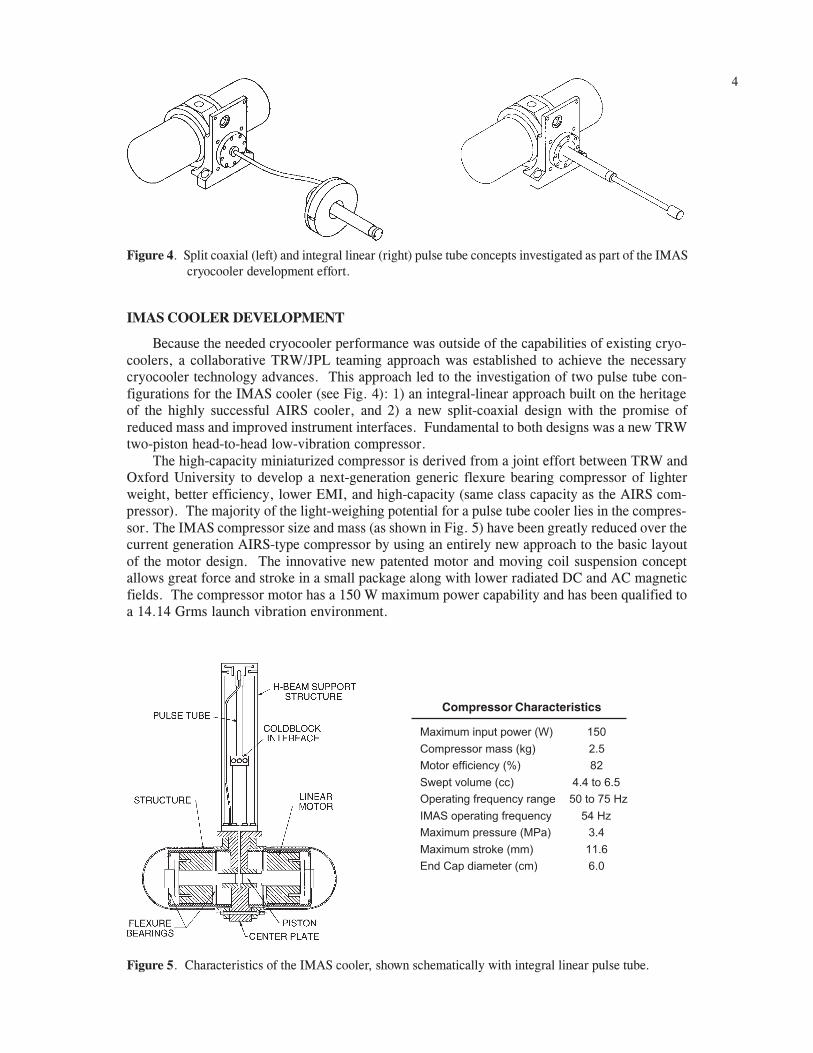
Figure 4. Split coaxial (left) and integral linear (right) pulse tube concepts investigated as part of the IMAScryocooler development effort.
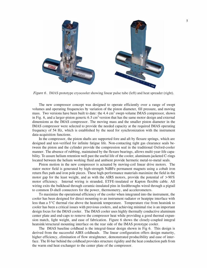
Figure 5. Characteristics of the IMAS cooler, shown schematically with integral linear pulse tube.
Compressor Characteristics
Maximum input power (W) 150
Compressor mass (kg) 2.5
Motor efficiency (%) 82
Swept volume (cc) 4.4 to 6.5
Operating frequency range 50 to 75 Hz
IMAS operating frequency 54 Hz
Maximum pressure (MPa) 3.4
Maximum stroke (mm) 11.6
End Cap diameter (cm) 6.0
IMAS COOLER DEVELOPMENT
Because the needed cryocooler performance was outside of the capabilities of existing cryo-coolers, a collaborative TRW/JPL teaming approach was established to achieve the necessarycryocooler technology advances. This approach led to the investigation of two pulse tube con-figurations for the IMAS cooler (see Fig. 4): 1) an integral-linear approach built on the heritageof the highly successful AIRS cooler, and 2) a new split-coaxial design with the promise ofreduced mass and improved instrument interfaces. Fundamental to both designs was a new TRWtwo-piston head-to-head low-vibration compressor.
The high-capacity miniaturized compressor is derived from a joint effort between TRW andOxford University to develop a next-generation generic flexure bearing compressor of lighterweight, better efficiency, lower EMI, and high-capacity (same class capacity as the AIRS com-pressor). The majority of the light-weighing potential for a pulse tube cooler lies in the compres-sor. The IMAS compressor size and mass (as shown in Fig. 5) have been greatly reduced over thecurrent generation AIRS-type compressor by using an entirely new approach to the basic layoutof the motor design. The innovative new patented motor and moving coil suspension conceptallows great force and stroke in a small package along with lower radiated DC and AC magneticfields. The compressor motor has a 150 W maximum power capability and has been qualified toa 14.14 Grms launch vibration environment.
5
Figure 6 . IMAS prototype cryocooler showing linear pulse tube (left) and heat spreader (right).
The new compressor concept was designed to operate efficiently over a range of sweptvolumes and operating frequencies by variation of the piston diameter, fill pressure, and movingmass. Two versions have been built to date: the 4.4 cm3 swept-volume IMAS compressor, shownin Fig. 6, and a larger-piston generic 6.5 cm3 version that has the same motor design and externaldimensions as the IMAS compressor. The moving mass and the smaller piston diameter in theIMAS compressor were selected to provide the needed capacity at the required IMAS operatingfrequency of 54 Hz, which is established by the need for synchronization with the instrumentdata-acquisition functions.
In the compressor, the piston shafts are supported fore and aft by flexure springs, which aredesigned and test-verified for infinite fatigue life. Non-contacting tight gas clearance seals be-tween the piston and the cylinder provide the compression seal in the traditional Oxford-coolermanner. The absence of rubbing, maintained by the flexure bearings, allows multi-year-life capa-bility. To assure helium retention well past the useful life of the cooler, aluminum-jacketed C-ringslocated between the helium working fluid and ambient provide hermetic metal-to-metal seals.
Piston motion in the new compressor is actuated by moving-coil linear drive motors. Thestator motor field is generated by high-strength NdBFe permanent magnets using a cobalt ironreturn flux path and iron pole pieces. These high-performance materials maximize the field in themotor gap for the least weight, and as with the AIRS motors, provide the potential of >90%motor efficiency. Internal wiring is stranded, ETFE-insulated or Kapton flexible cable. Allwiring exits the bulkhead through ceramic-insulated pins in feedthroughs wired through a pigtailto common D-shell connectors for the power, thermometry, and accelerometers.
To maximize the operational efficiency of the cooler when integrated into the instrument, thecooler has been designed for direct mounting to an instrument radiator or heatpipe interface withless than a 5°C thermal rise above the heatsink temperature. Temperature rise from heatsink tocooler has been a critical issues with previous coolers, and achieving minimal rise is an importantdesign focus for the IMAS cooler. The IMAS cooler uses highly thermally conductive aluminumcenter plate and end-caps to remove the compressor heat while providing a good thermal expan-sion match, light weight, and ease of fabrication. Figure 6 shows the closely-coupled integralheatsink/structural mounting interface on the rear side of the IMAS prototype cooler.
The IMAS baseline coldhead is the integral-linear design shown in Fig 6. This design isderived from the successful AIRS coldheads. The linear configuration offers design maturity,higher efficiency, elimination of flow straightener, demonstrated producibility and ease of inter-face. The H-bar behind the coldhead provides structure rigidity and the heat conduction path fromthe warm end heat exchanger to the center plate of the compressor.

6
Figure 7. Prototype coaxial pulse tube coldhead.
In addition to the linear configuration, a coaxial coldhead, derived from TRW IRAD, wasalso designed for the IMAS cooling load. The coaxial configuration, shown in Fig. 7, offers analternative focal plane interface and a potential cooler mass reduction through elimination of thepulse tube structural support.
Either the linear or the coaxial coldhead can be integrated with the IMAS compressor in anintegral or in a split configuration. The coaxial split configuration provides an alternate for anadvanced focal plane design, especially if the base of the regenerator can be thermally mountedonto a lower-temperature radiator and the focal plane can be mounted directly onto the coldtip.The IMAS coaxial configuration offers a 50% reduction in coldhead mass because it does notrequire the H-bar. From the system point of view, the cooling load of the coaxial split configu-ration is also reduced.
IMAS Engineering Model Coolers
Based on the initial test experience with the Prototype IMAS cooler shown in Fig. 6 and withthe coaxial pulse tube shown in Fig. 7, two IMAS Engineering Model coolers were assembled fordetailed performance evaluation and exploratory qualification testing. These units used the com-pressor from the IMAS prototype cooler together with two variations of more highly optimizedlinear pulse tube expanders and two variations of coldend packaging of the reservoir volume andorifice lines. One of these units (Fig. 8) is configured with a longer pulse tube and an integral
Figure 8. IMAS Engineering Model cooler #101 with reservoir volume integral with the pulse tubestructural support and integral vacuum housing.

7
Mechanical Refrigerator Total 4.03 3.60 2.98Compressor 2.50 2.50 2.50Pulse tube cold head 0.25 0.24 0.24Vacuum Can / Shield 0.68 N/A 0Reservoir Tank and Line 0.60 0.86 0.800
Cryocooler Electronics (w/ripple suppression) 6.50 6.50 6.50Cables (Electronics to Mech. Cooler) 0.50 0.50 0.50
Total Cryocooler Mass 11.03 10.6 9.98
Figure 9. IMAS Engineering Model cooler #102 with reservoir volume integral with the pulse tubestructural support, but no integral vacuum housing.
Mass (kg)#101 Linear #102 Linear Split-Coaxial
Table 3. IMAS cryocooler mass summary.
vacuum housing containing the reservoir volume and orifice line, whereas the second unit (Fig. 9)is configured with a shorter pulse tube and a combined reservoir volume and H-beam similar toTRW's mini pulse tube.
The masses of the two IMAS EM coolers and an estimate of the mass of a split-coaxialconfiguration of the cooler are summarized in Table 3.
IMAS Flight Cooler Electronics
Another key issue addressed by the IMAS cooler development is compatibility with thesensitive IR and millimeter-wave detectors and electronics and the spacecraft power system. Toreduce noise input to the detector circuits to very low levels, the IMAS cooler baselines the use ofTRWs flight qualified, radiation-hardened, and high-efficiency AIRS/SMTS/TES cooler elec-tronics family. These cooler electronics provide electrical isolation from the spacecraft powerbus and use digitally generated piston waveforms to provide precise closed-loop suppression ofgenerated vibration and to provide millikelvin temperature control of the cooler coldfinger so asto achieve the needed fractional millikelvin stability at the focal plane. The key driver on thetemperature control is the fluctuating temperature of the cryocooler heatsink due to orbital varia-tions in the effective thermal radiation environment, including periodic solar input in some cir-cumstances. From previous measurements of space coolers it is known that every 5°C change inheatsink temperature maps into approximately a 1 K change in coldtip temperature for the samestroke or input power.8,1
ITEM

8
Figure 10. Packaging concept and design goals for the new IMAS cryocooler drive electronics.
ITEM Design Goal
Output Power 25W to 60WInput Voltage (Operating) 20-36VMax Voltage (non operating) 50VMin. Isolation (Bus to Chassis) 1 µF & 106 ΩBus Ripple Current Max 1 A rms
Standby Bleeder Power Max 2 WElectronic Parts Quality Mil 883B, Grade 2Radiation Dose and SEU 20 kradPower Slice Efficiency 78% Min.Operating Temperature -45°C to +50°CLaunch Vibration 12.9 G rms
Total Mass 6.5 kgBus Power 34W to 79W
Figure 11. Photo of the IMAS rackmounted brassboard ripple suppression electronics.
In addition to the vibration and temperature control functions, the software programmabledrive electronics also provide for cooler operational control, and acquisition and transmission ofcooler operational data to the IMAS instrument. Relays in the electronics short the compressormotor drive coils during launch to prevent excessive launch-induced piston motion. Design goalsfor the IMAS electronics are summarized in Fig. 10.
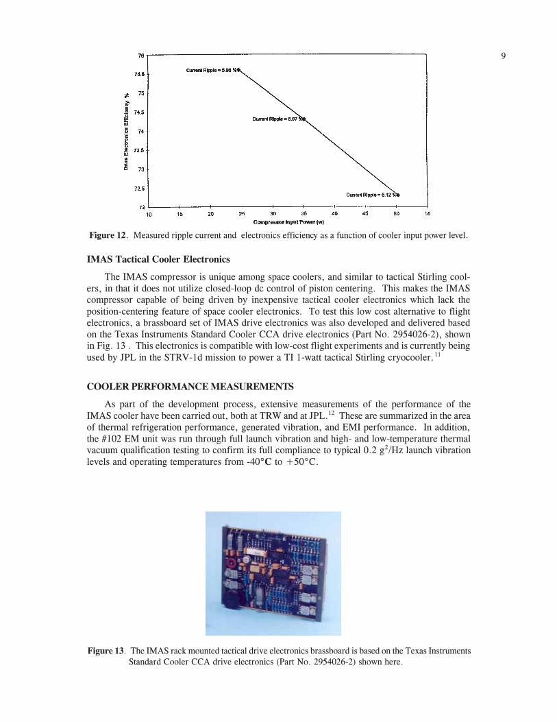
As an augmentation to the AIRS/SMTS/TES cooler electronics, the IMAS cooler develop-ment effort redesigned the power handling portion of the electronics to include a high level ofactive ripple current suppression. Excessive ripple current fed onto the input power bus is acommon problem for all low-frequency linear drive coolers,9,10 and has been solved to date by theaddition of a separate ripple filter in the spacecraft power system. The new ripple-suppressioncooler electronics designed as part of the IMAS cryocooler development effort represents a po-tential savings of several kilograms of total system mass, and greatly improves spacecraft accom-modation. Figure 11 is a photograph of the rackmounted brassboard ripple suppression electron-ics developed and delivered with the IMAS cryocooler; Figure 12 presents the excellent mea-sured ripple current levels as a function of cooler drive power. The weight of the IMAS coolerelectronics with ripple current suppression is estimated to be around 6.5 kg, as is shown inTable 3. Without the integral ripple filter, AIRS measurements1 suggest that the projected elec-trical efficiency is well modeled as P(total input) = P(compressor input)/0.85+5 watts. Becauseof the addition of the ripple current filter, the IMAS electronics is projected to be P(totalinput)=P(compressor input)/0.78 + 2 watts.
9
Figure 13. The IMAS rack mounted tactical drive electronics brassboard is based on the Texas InstrumentsStandard Cooler CCA drive electronics (Part No. 2954026-2) shown here.
Figure 12. Measured ripple current and electronics efficiency as a function of cooler input power level.
IMAS Tactical Cooler Electronics
The IMAS compressor is unique among space coolers, and similar to tactical Stirling cool-ers, in that it does not utilize closed-loop dc control of piston centering. This makes the IMAScompressor capable of being driven by inexpensive tactical cooler electronics which lack theposition-centering feature of space cooler electronics. To test this low cost alternative to flightelectronics, a brassboard set of IMAS drive electronics was also developed and delivered basedon the Texas Instruments Standard Cooler CCA drive electronics (Part No. 2954026-2), shownin Fig. 13 . This electronics is compatible with low-cost flight experiments and is currently beingused by JPL in the STRV-1d mission to power a TI 1-watt tactical Stirling cryocooler.11
COOLER PERFORMANCE MEASUREMENTS
As part of the development process, extensive measurements of the performance of theIMAS cooler have been carried out, both at TRW and at JPL.12 These are summarized in the areaof thermal refrigeration performance, generated vibration, and EMI performance. In addition,the #102 EM unit was run through full launch vibration and high- and low-temperature thermalvacuum qualification testing to confirm its full compliance to typical 0.2 g2/Hz launch vibrationlevels and operating temperatures from -40°C to +50°C.
10
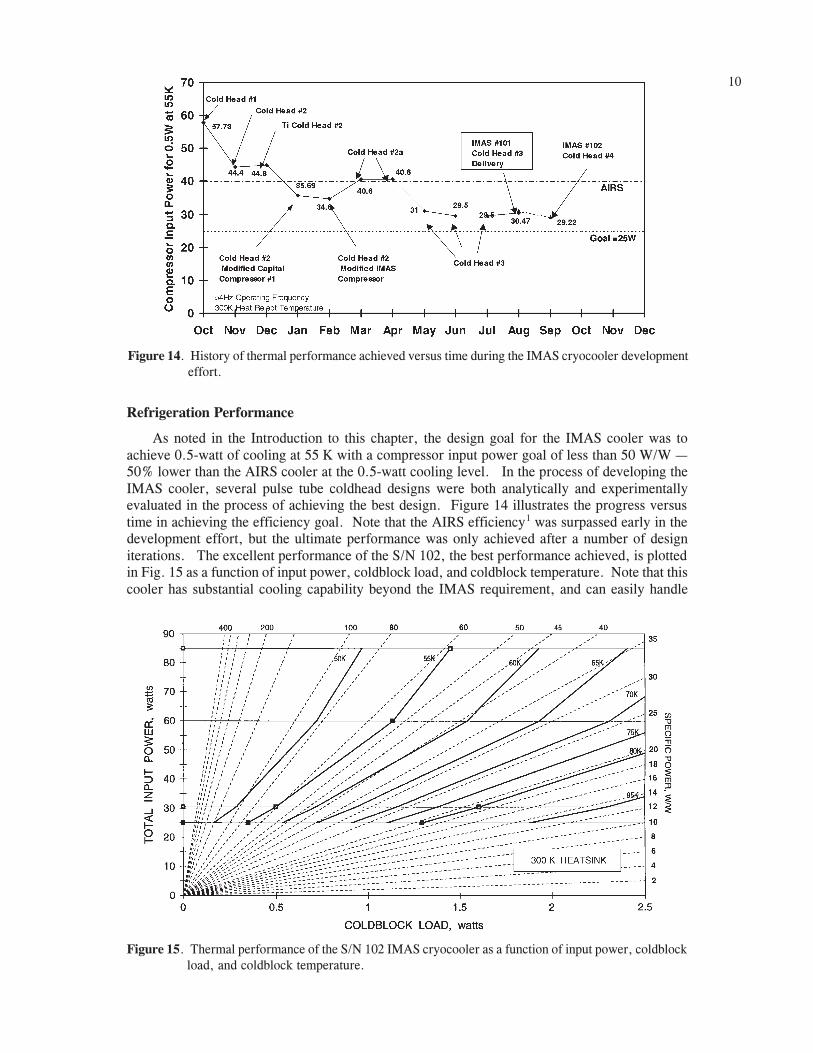
Figure 15. Thermal performance of the S/N 102 IMAS cryocooler as a function of input power, coldblockload, and coldblock temperature.
Figure 14. History of thermal performance achieved versus time during the IMAS cryocooler developmenteffort.
Refrigeration Performance
As noted in the Introduction to this chapter, the design goal for the IMAS cooler was toachieve 0.5-watt of cooling at 55 K with a compressor input power goal of less than 50 W/W 50% lower than the AIRS cooler at the 0.5-watt cooling level. In the process of developing theIMAS cooler, several pulse tube coldhead designs were both analytically and experimentallyevaluated in the process of achieving the best design. Figure 14 illustrates the progress versustime in achieving the efficiency goal. Note that the AIRS efficiency1 was surpassed early in thedevelopment effort, but the ultimate performance was only achieved after a number of designiterations. The excellent performance of the S/N 102, the best performance achieved, is plottedin Fig. 15 as a function of input power, coldblock load, and coldblock temperature. Note that thiscooler has substantial cooling capability beyond the IMAS requirement, and can easily handle

11
Figure 16. TES cryocooler (left) in comparison with the new IMAS cryocooler (right)
Figure 17. Sensitivity of specific power to heat reject temperature for the IMAS pulse tube cryocooler atan 85 watt input power level
cooling loads similar to those (1 W at 57 K) required by the TES instrument. Figure 16 directlycompares the size of the IMAS and TES cryocoolers.
Because heat rejection temperature has a strong effect on cryocooler performance, data werealso taken on the change in specific power for three coldblock temperatures (55, 80 and 100 K);these data are presented in Fig. 17.
Potential for Future Efficiency Increase Although the efficiency of the IMAS cooler isvery high, the efficiency of a future flight version of the IMAS cooler would be expected to beeven higher by increasing the motor efficiency to about 86% from the present 80%. This in-crease follows logically based on incorporating high-efficiency drive coils similar to those provenin the AIRS and TES compressors. The IMAS #101 and #102 EM compressors fabricated duringthis effort were outfitted with less sophisticated drive coils for schedule and cost reasons. Incor-porating the high-efficiency drive coils would result in an ultimate performance of approximately27 watts required for the 0.5 watts at 55 K very close to the original IMAS goal.

12Self-Induced Vibration Performance
As part of the exploratory testing effort, the self-induced vibration of the IMAS cooler wastested in a variety of configurations with both low-harmonic-distortion sinusoidal-waveform labo-ratory drive electronics and low cost tactical cooler drive electronics. Figures 18 and 19 presentdata for vibration in both the drive axis and cross axis using the low-harmonic-distortion sinusoi-dal-waveform laboratory drive electronics. The left-most bar, labeled "Quadbox, Dual Amps"corresponds to using two separate sinusoidal drives, one for each compressor half, and usingcareful drive-axis nulling of the first 16 harmonics, as is done automatically by the AIRS/TES-style drive electronics. The middle bar, labeled "Parallel Coils, Single Amp" is for a singlesinusoidal amplifier driving the two compressor coils in parallel; no harmonic nulling is possiblefor this case as there is no independent control of the harmonic content of the current going to the
Figure 19. Very low self induced vibration normal to the drive axis of the #101 cooler for the IMASoperating point of 30-watts input power and 0.5-watt cooling at 55 K.
Figure 18. Self induced vibration in the compressor drive axis of the #101 cooler for the IMAS operatingpoint of 30-watts input power and 0.5-watt cooling at 55 K.

13
Figure 20. Self induced vibration of the S/N 102 IMAS cryocooler when powered by low-distortion labelectronics (top), and square-wave tactical cooler drive electronics (bottom).
two compressor drive coils. The third case, labeled "Series Coils, Single Amp" is similar to themiddle case, but with the two coils wired in series; this yields the same current in both coils.Note that the series case (right bar) gives the lowest vibration of the single-amp cases, while thedual-amp case with harmonic nulling gives very low vibration levels, well below the IMAS/AIRSrequirement.
Vibration with Tactical Cooler Electronics To understand the possible influence of tacticalcooler electronics on self-induced vibration levels, a separate somewhat qualitative test was per-formed. This test used both the sinusoidal drive electronics as used in Figs. 18 and 19 and theTexas Instruments Standard Cooler CCA drive electronics (Part No. 2954026-2), which gener-ates a square waveform rather than a sinusoidal waveform. As seen in Fig. 20, the self-inducedvibration levels are quite similar for the two electronics. However, in the tactical square-wave-form case, about 20% of the cooling capacity at 75K was lost for the same input power due toexcessive levels of high harmonics.
EMI Performance
Another feature of the smaller, lower-power motors in the IMAS cooler is lower levels ofAC magnetic fields. Two sets of AC magnetic field measurements were made to quantify theIMAS cryocooler AC magnetic field emissions: 1) at a 7-cm distance, corresponding to the MIL-STD-461C RE01 test specification9, and 2) at a 1-m distance, corresponding to a MIL-STD-462RE04 test method. Figure 21 shows the measured RE01 magnetic field performance of the IMAScompressor at 75 watt input power, contrasted with that of the AIRS compressor shown for105 watts of input power10; the data are plotted in decibels above 1 pT. The magnetic fieldemission levels of the IMAS cooler are quite low compared to other space coolers.9

14
SUMMARY AND CONCLUSIONS
The IMAS TechDemo cryocooler development effort has led to a highly successful state-of-the-art pulse tube cooler with excellent thermal performance, light weight, low self-induced vi-bration, and low magnetic field emissions. The success of the effort is a credit to the work havingbeen carried out as a close collaboration between the IMAS instrument cryosystem developmentteam at JPL and the cryocooler development team at TRW. The result is a major advance incryocooler performance and improved instrument accommodation.
ACKNOWLEDGEMENT
The development of the IMAS cryocooler took place at TRW Space & Technology Division,Redondo Beach, CA under JPL Contract No. 960763. Key TRW personel invloved in the effortinclude C.K. Chan, T. Nguyen, R. Colbert, and J. Raab. Special recognition is also due D.Johnson and S. Leland of JPL who conducted the characterization testing of the cooler at JPL.
REFERENCES
1. Ross, R.G., et al., AIRS PFM Pulse Tube Cooler System-level Performance, Cryocoolers 10,Plenum Publishing Corp., New York, 1999, pp. 119-128.
2. Chan, C.K., Raab, J., Colbert, R. , Carlson, C, and Orsini, R.,Pulse Tube Coolers for NASAAIRS Flight Instrument, Proceedings of ICEC 17, 14-17 July 1998, Bournemouth, UK.
3. Ross, R.G., Jr. and Green K., AIRS Cryocooler System Design and Development, Cryocoolers 9,Plenum Publishing Corp., New York, 1997, pp. 885-894.
4. Chan, C.K., et al., Performance of the AIRS Pulse Tube Engineering Model Cryocooler, Cryo-coolers 9, Plenum Publishing Corp., New York, 1997, pp. 195-202.
5. Chan, C.K., et al., AIRS Pulse Tube Cryocooler System, Cryocoolers 9, Plenum PublishingCorp., New York, 1997, pp. 895-903.
6. Tward, E., et al., Miniature Long-Life Space-Qualified Pulse Tube and Stirling Cryocoolers,Cryocoolers 8, Plenum Publishing Corp., New York, 1995, pp. 329-336.
7. Chan, C.K., Jaco, C. and Nguyen, T., Advanced Pulse Tube Cold Head Development, Cryocool-ers 9, Plenum Publishing Corp., New York, 1997, pp. 203-212.
8. Ross, R.G., Jr. and Johnson, D.L., Effect of Heat Rejection Conditions on Cryocooler OperationalStability, Advances in Cryogenic Engineering, Vol. 43, 1998, pp. 1745-1752.
9. Johnson, D.L., et al., "Cryocooler Electromagnetic Compatibility," Cryocoolers 8, Plenum Publish-ing Corp., New York, 1995, pp. 209-220.
Figure 21. Radiated magnetic fields of the S/N 102 IMAS cryocooler (left) in contrast to those from thelarger AIRS cooler (right).

1510. Johnson, D.L., Collins, S.A. and Ross, R.G., Jr., "EMI Performance of the AIRS Cooler andElectronics," Cryocoolers 10, Plenum Publishing Corp., New York, 1999, pp. 771-780.
11. Johnson, D.L., Thermal Performance of the Texas Instruments 1-watt Linear Drive Cryocooler,Cryocoolers 10, Plenum Publishing Corp., New York, 1999, pp. 95-104.
12. Chan, C.K., Ross, R.G., Jr., et al., "IMAS Pulse Tube Cooler Development and Testing," Cryocool-ers 10, Plenum Publishing Corp., New York, 1999, pp. 139-147.